EP3457423B1 - Change-over switch - Google Patents
Change-over switch Download PDFInfo
- Publication number
- EP3457423B1 EP3457423B1 EP17191315.5A EP17191315A EP3457423B1 EP 3457423 B1 EP3457423 B1 EP 3457423B1 EP 17191315 A EP17191315 A EP 17191315A EP 3457423 B1 EP3457423 B1 EP 3457423B1
- Authority
- EP
- European Patent Office
- Prior art keywords
- gas discharge
- discharge passage
- change
- over switch
- side wall
- Prior art date
- Legal status (The legal status is an assumption and is not a legal conclusion. Google has not performed a legal analysis and makes no representation as to the accuracy of the status listed.)
- Active
Links
- 239000004020 conductor Substances 0.000 claims description 5
- 238000007599 discharging Methods 0.000 claims description 5
- 239000000463 material Substances 0.000 claims description 3
- 239000007789 gas Substances 0.000 description 66
- 238000010891 electric arc Methods 0.000 description 5
- 238000009413 insulation Methods 0.000 description 2
- 239000002923 metal particle Substances 0.000 description 2
- RYGMFSIKBFXOCR-UHFFFAOYSA-N Copper Chemical compound [Cu] RYGMFSIKBFXOCR-UHFFFAOYSA-N 0.000 description 1
- 229910000831 Steel Inorganic materials 0.000 description 1
- 230000001419 dependent effect Effects 0.000 description 1
- 239000003574 free electron Substances 0.000 description 1
- 239000002184 metal Substances 0.000 description 1
- 229910052751 metal Inorganic materials 0.000 description 1
- 230000008023 solidification Effects 0.000 description 1
- 238000007711 solidification Methods 0.000 description 1
- 239000004071 soot Substances 0.000 description 1
- 239000010959 steel Substances 0.000 description 1
Images


Classifications
-
- H—ELECTRICITY
- H01—ELECTRIC ELEMENTS
- H01H—ELECTRIC SWITCHES; RELAYS; SELECTORS; EMERGENCY PROTECTIVE DEVICES
- H01H19/00—Switches operated by an operating part which is rotatable about a longitudinal axis thereof and which is acted upon directly by a solid body external to the switch, e.g. by a hand
- H01H19/50—Switches operated by an operating part which is rotatable about a longitudinal axis thereof and which is acted upon directly by a solid body external to the switch, e.g. by a hand the operating part having four operative positions, e.g. off/two-in-series/one-only/two-in-parallel
-
- H—ELECTRICITY
- H01—ELECTRIC ELEMENTS
- H01H—ELECTRIC SWITCHES; RELAYS; SELECTORS; EMERGENCY PROTECTIVE DEVICES
- H01H9/00—Details of switching devices, not covered by groups H01H1/00 - H01H7/00
- H01H9/30—Means for extinguishing or preventing arc between current-carrying parts
- H01H9/34—Stationary parts for restricting or subdividing the arc, e.g. barrier plate
- H01H9/342—Venting arrangements for arc chutes
-
- H—ELECTRICITY
- H01—ELECTRIC ELEMENTS
- H01H—ELECTRIC SWITCHES; RELAYS; SELECTORS; EMERGENCY PROTECTIVE DEVICES
- H01H1/00—Contacts
- H01H1/12—Contacts characterised by the manner in which co-operating contacts engage
- H01H1/36—Contacts characterised by the manner in which co-operating contacts engage by sliding
- H01H1/365—Bridging contacts
-
- H—ELECTRICITY
- H01—ELECTRIC ELEMENTS
- H01H—ELECTRIC SWITCHES; RELAYS; SELECTORS; EMERGENCY PROTECTIVE DEVICES
- H01H1/00—Contacts
- H01H1/12—Contacts characterised by the manner in which co-operating contacts engage
- H01H1/36—Contacts characterised by the manner in which co-operating contacts engage by sliding
- H01H1/42—Knife-and-clip contacts
-
- H—ELECTRICITY
- H01—ELECTRIC ELEMENTS
- H01H—ELECTRIC SWITCHES; RELAYS; SELECTORS; EMERGENCY PROTECTIVE DEVICES
- H01H19/00—Switches operated by an operating part which is rotatable about a longitudinal axis thereof and which is acted upon directly by a solid body external to the switch, e.g. by a hand
- H01H19/46—Switches operated by an operating part which is rotatable about a longitudinal axis thereof and which is acted upon directly by a solid body external to the switch, e.g. by a hand the operating part having three operative positions, e.g. off/star/delta
-
- H—ELECTRICITY
- H01—ELECTRIC ELEMENTS
- H01H—ELECTRIC SWITCHES; RELAYS; SELECTORS; EMERGENCY PROTECTIVE DEVICES
- H01H19/00—Switches operated by an operating part which is rotatable about a longitudinal axis thereof and which is acted upon directly by a solid body external to the switch, e.g. by a hand
- H01H19/64—Encased switches adapted for ganged operation when assembled in a line with identical switches, e.g. stacked switches
-
- H—ELECTRICITY
- H01—ELECTRIC ELEMENTS
- H01H—ELECTRIC SWITCHES; RELAYS; SELECTORS; EMERGENCY PROTECTIVE DEVICES
- H01H71/00—Details of the protective switches or relays covered by groups H01H73/00 - H01H83/00
- H01H71/08—Terminals; Connections
-
- H—ELECTRICITY
- H01—ELECTRIC ELEMENTS
- H01H—ELECTRIC SWITCHES; RELAYS; SELECTORS; EMERGENCY PROTECTIVE DEVICES
- H01H1/00—Contacts
- H01H1/12—Contacts characterised by the manner in which co-operating contacts engage
- H01H1/14—Contacts characterised by the manner in which co-operating contacts engage by abutting
- H01H1/20—Bridging contacts
- H01H1/2041—Rotating bridge
- H01H1/2058—Rotating bridge being assembled in a cassette, which can be placed as a complete unit into a circuit breaker
-
- H—ELECTRICITY
- H01—ELECTRIC ELEMENTS
- H01H—ELECTRIC SWITCHES; RELAYS; SELECTORS; EMERGENCY PROTECTIVE DEVICES
- H01H1/00—Contacts
- H01H1/58—Electric connections to or between contacts; Terminals
- H01H1/5822—Flexible connections between movable contact and terminal
-
- H—ELECTRICITY
- H01—ELECTRIC ELEMENTS
- H01H—ELECTRIC SWITCHES; RELAYS; SELECTORS; EMERGENCY PROTECTIVE DEVICES
- H01H73/00—Protective overload circuit-breaking switches in which excess current opens the contacts by automatic release of mechanical energy stored by previous operation of a hand reset mechanism
- H01H73/02—Details
- H01H73/04—Contacts
- H01H73/045—Bridging contacts
Definitions
- the present invention relates to a change-over switch.
- a change-over switch is a switching device comprising a first supply terminal, a second supply terminal and a load terminal, and adapted to selectively provide a first connection between the first supply terminal and the load terminal, and a second connection between the second supply terminal and the load terminal.
- the gas discharge arrangement enables expanded gas to discharge from the frame of the change-over switch, which prevents pressure inside the frame from becoming too high.
- One of the problems associated with known change-over switches is that in connection with a switching event, gas discharging from the frame through the gas flow openings may cause a short circuit.
- said short circuit may occur between a terminal of the change-over switch and an adjacent earthed part, or between terminals of the change-over switch. Risk for the short circuit may increase gradually due to electrically conductive material that is deposited in the vicinity of the gas flow openings.
- An object of the present invention is to provide a change-over switch so as to solve the above problem.
- the objects of the invention are achieved by a change-over switch which is characterized by what is stated in the independent claim 1.
- the preferred embodiments of the invention are disclosed in the dependent claims.
- the invention is based on the idea of locating a first supply terminal and a second supply terminal on a first side wall of a frame of a change-over switch while a load terminal is located on a second side wall facing substantially opposite direction relative to the first side wall, and providing the change-over switch with a gas discharge arrangement adapted to discharge gasses produced by switching events through gas flow opening(s) formed in the second side wall.
- An advantage of the change-over switch of the invention is that a risk of a short circuit is reduced in connection with opening a current circuit of the change-over switch, because the gas flow opening(s) are on the same side wall as the load terminal which is at the same electric potential as the supply terminal whose current circuit is being opened in the switching event in question.
- long gas discharge passages cool gasses produced by switching events, and remove at least part of metal particles vaporized from contact surfaces by the switching events. Lowering temperature of the exhaust gases lowers electrical conductivity of the exhaust gases. Reducing amount of metal particles in the gas flow exiting the frame reduces amount of electrically conductive material that is deposited outside the gas flow openings, in the vicinity of the gas flow openings.
- Figure 1 shows a change-over switch comprising a frame 2, a first supply terminal 41 adapted to be connected to a first power supply, a second supply terminal 42 adapted to be connected to a second power supply, and a load terminal 6 adapted to be connected to a load.
- the first supply terminal 41 and the second supply terminal 42 project from a first side wall 21, and the load terminal 6 projects from a second side wall 22.
- the second side wall 22 faces substantially opposite direction relative to the first side wall 21.
- the first side wall 21 and the second side wall 22 are spaced apart in a longitudinal direction.
- the change-over switch of Figure 1 is a single-phase module adapted to be coupled to other modules in order to provide a multiphase change-over switch.
- Figure 2 is a side view of the change-over switch of Figure 1 .
- a half of the frame 2 has been removed so as to show an internal structure of the change-over switch.
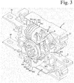
- Figure 3 shows the change-over switch of Figure 1 with half of the frame 2 removed.
- Figures 2 and 3 show that the change-over switch comprises a selector contact 8, a gas discharge arrangement, a plurality of first arc extinguisher plates 941 and a plurality of second arc extinguisher plates 942.
- the gas discharge arrangement comprises a first gas discharge passage 51, a second gas discharge passage 52, a first gas flow opening 31 and a second gas flow opening 32.
- the first gas discharge passage 51 comprises a remote portion 514, an outer portion 515 and a plate portion 519.
- the second gas discharge passage 52 comprises a remote portion 524, an outer portion 525 and a plate portion 529.
- the selector contact 8 is adapted to rotate relative to the frame 2 around a rotation axis 81 between a first position and a second position.
- the rotation axis 81 is perpendicular to the longitudinal direction.
- the selector contact 8 In the first position the selector contact 8 electrically conductively connects the first supply terminal 41 to the load terminal 6, and electrically isolates the second supply terminal 42 from the load terminal 6.
- the selector contact 8 In the second position the selector contact 8 electrically conductively connects the second supply terminal 42 to the load terminal 6, and electrically isolates the first supply terminal 41 from the load terminal 6.
- the frame 2 is made from material whose electrical conductivity is low.
- the selector contact 8 comprises a first blade contact 851 for establishing electrically conductive connection with the first supply terminal 41, and a second blade contact 852 for establishing electrically conductive connection with the second supply terminal 42.
- Electrically conductive connection between the selector contact 8 and the first supply terminal 41 is adapted to be closed and opened in a first contact zone 91.
- Electrically conductive connection between the selector contact 8 and the second supply terminal 42 is adapted to be closed and opened in a second contact zone 92.
- the contact zones 91 and 92, and the plurality of first arc extinguisher plates 941 and the plurality of second arc extinguisher plates 942 are located inside the frame 2.
- the selector contact 8 is in a fixed electrically conductive connection with the load terminal 6.
- the fixed electrically conductive connection between the selector contact 8 and the load terminal 6 comprises two braided conductors 801 and 802, which are adapted to allow rotation between the selector contact 8 and the load terminal 6 due to flexibility thereof.
- the braided conductors 801 and 802 are made from copper wire.
- the gas discharge arrangement is adapted for discharging gasses produced by switching events from the frame 2.
- the switching events comprise a first type switching event occurring between the selector contact 8 and the first supply terminal 41, and a second type switching event occurring between the selector contact 8 and the second supply terminal 42.
- the first type switching event takes place in the first contact zone 91
- the second type switching event takes place in the second contact zone 92.
- the first gas flow opening 31 and the second gas flow opening 32 are formed in the second side wall 22, and adapted to provide a flow path for the gasses from inside the frame 2 to outside the frame 2.
- the first gas flow opening 31 is adapted for gasses produced in the first type switching event.
- the second gas flow opening 32 is adapted for gasses produced in the second type switching event.
- the first gas flow opening 31 and the second gas flow opening 32 are located on opposite sides of the load terminal 6 in a height direction.
- the height direction is perpendicular to the longitudinal direction and a width direction, the width direction being parallel to the rotation axis 81.
- the first gas discharge passage 51 originates from the first contact zone 91 and ends to the first gas flow opening 31.
- the second gas discharge passage 52 originates from the second contact zone 92 and ends to the second gas flow opening 32.
- both the first gas discharge passage and the second gas discharge passage end to the same gas flow opening.
- both the first gas flow opening and the second gas flow opening comprise a plurality of sub-openings.
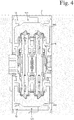
- Figure 4 shows a cross section of the change-over switch of Figure 1 taken along a plane parallel to the first side wall 21 of the switch, and passing through the selector contact 8.
- Figure 4 shows that a width of each of the outer portions 515 and 525 is substantially equal to inner width of the frame 2. Further, a cross-sectional area of each of the outer portions 515 and 525 is sufficient to provide a low resistance path for the gasses.
- Figures 2 , 3 and 4 show that the first gas discharge passage 51 provides a path of least resistance for a gas flow from the first contact zone 91 to the first gas flow opening 31, and the second gas discharge passage 52 provides a path of least resistance for a gas flow from the second contact zone 92 to the second gas flow opening 32.
- the first contact zone 91 and the second side wall 22 are located on opposite sides of the rotation axis 81 in the longitudinal direction.
- the second contact zone 92 and the second side wall 22 are located on opposite sides of the rotation axis 81 in the longitudinal direction. Therefore both the first gas discharge passage 51 and the second gas discharge passage 52 are long passages allowing gasses produced by switching events to cool properly before discharging the gasses from the frame 2.
- the plurality of first arc extinguisher plates 941 is located adjacent the first contact zone 91 and adapted to extinguish electric arcs produced in the first type switching event.
- the plurality of first arc extinguisher plates 941 is located between the rotation axis 81 and the outer portion 515 of the first gas discharge passage 51 in a radial direction perpendicular to the rotation axis 81.
- the plurality of second arc extinguisher plates 942 is located adjacent the second contact zone 92 and adapted to extinguish electric arcs produced in the second type switching event.
- the plurality of second arc extinguisher plates 942 is located between the rotation axis 81 and the outer portion 525 of the second gas discharge passage 52 in a radial direction perpendicular to the rotation axis 81. Majority of both the first arc extinguisher plates 941 and the second arc extinguisher plates 942 are located on opposite side of the rotation axis 81 than the second side wall 22 in the longitudinal direction.
- the remote portion 514 of the first gas discharge passage 51 is located further from the second side wall 22 in the longitudinal direction than the plurality of first arc extinguisher plates 941.
- the remote portion 524 of the second gas discharge passage 52 is located further from the second side wall 22 in the longitudinal direction than the plurality of second arc extinguisher plates 942.
- Gasses passing through the remote portions 514 and 524 travel substantially longer distance than a direct distance between the corresponding contact zone and gas flow opening. Further, when flowing from a contact zone to corresponding remote portion, gasses actually recede from corresponding gas flow opening, which makes the path of the gasses longer and allows the gasses to cool more.
- Each of the plurality of first arc extinguisher plates 941 and each of the plurality of second arc extinguisher plates 942 is a substantially planar element which defines a corresponding extinguisher plate plane.
- the extinguisher plate plane of each first arc extinguisher plate 941 and each second arc extinguisher plate 942 is positioned such that a radial direction is substantially parallel to the extinguisher plate plane, the radial direction is a direction perpendicular to the rotation axis 81.
- the shape of the arc extinguisher plates 941 and 942 can be best seen in Figures 3 and 4 .
- Each of the plurality of first arc extinguisher plates 941 and each of the plurality of second arc extinguisher plates 942 is made from zinc-plated steel.
- Each of the first arc extinguisher plates 941 and each of the plurality of second arc extinguisher plates 942 is electrically isolated from the other arc extinguisher plates 941 and 942.
- each of the plurality of first arc extinguisher plates and each of the plurality of second arc extinguisher plates is made from another material with high electrical and thermal conductivity.
- the plate portion 519 of the first gas discharge passage 51 extends between the plurality of first arc extinguisher plates 941.
- the plate portion 529 of the second gas discharge passage 52 extends between the plurality of second arc extinguisher plates 942.
- the plate portion 519 of the first gas discharge passage 51 is in gas connection with the outer portion 515 of the first gas discharge passage 51.
- the plate portion 529 of the second gas discharge passage 52 is in gas connection with the outer portion 525 of the second gas discharge passage 52.
- Plate portions 519 and 529 of the gas discharge passages 51 and 52 cool gasses passing through them effectively due to high thermal conductivity of the arc extinguisher plates 941 and 942.
- the arc extinguisher plates 941 and 942 are adapted to absorb heat from gasses passing through the plate portions 519 and 529.
Description
- The present invention relates to a change-over switch.
- A change-over switch is a switching device comprising a first supply terminal, a second supply terminal and a load terminal, and adapted to selectively provide a first connection between the first supply terminal and the load terminal, and a second connection between the second supply terminal and the load terminal. When a current circuit of a change-over switch is opened, an electric arc whose temperature is thousands of degrees may occur in the change-over switch. An electric arc includes ionized gas, which contains a large number of free electrons. Such a gas plasma is electrically conductive.
- In addition to the fact that electric arc is conductive, metal which has been vaporized from contact surfaces by the electric arc may, upon solidification, impair the insulation capacity of the surfaces of the switching device. Soot produced by the electric arc may also cause insulation problems.
- It is known in the art to provide a change-over switch with a gas discharge arrangement for discharging gasses produced by switching events from a frame of the change-over switch, the gas discharge arrangement comprising gas flow openings formed in a side wall of the frame. The gas discharge arrangement enables expanded gas to discharge from the frame of the change-over switch, which prevents pressure inside the frame from becoming too high.
- One of the problems associated with known change-over switches is that in connection with a switching event, gas discharging from the frame through the gas flow openings may cause a short circuit. Depending on the design of the change-over switch, and the environment of the change-over switch, said short circuit may occur between a terminal of the change-over switch and an adjacent earthed part, or between terminals of the change-over switch. Risk for the short circuit may increase gradually due to electrically conductive material that is deposited in the vicinity of the gas flow openings.
- Examples of known switching devices are described in publications
GB193538 DE102013202811 . - An object of the present invention is to provide a change-over switch so as to solve the above problem. The objects of the invention are achieved by a change-over switch which is characterized by what is stated in the independent claim 1. The preferred embodiments of the invention are disclosed in the dependent claims.
- The invention is based on the idea of locating a first supply terminal and a second supply terminal on a first side wall of a frame of a change-over switch while a load terminal is located on a second side wall facing substantially opposite direction relative to the first side wall, and providing the change-over switch with a gas discharge arrangement adapted to discharge gasses produced by switching events through gas flow opening(s) formed in the second side wall.
- An advantage of the change-over switch of the invention is that a risk of a short circuit is reduced in connection with opening a current circuit of the change-over switch, because the gas flow opening(s) are on the same side wall as the load terminal which is at the same electric potential as the supply terminal whose current circuit is being opened in the switching event in question. Further, long gas discharge passages cool gasses produced by switching events, and remove at least part of metal particles vaporized from contact surfaces by the switching events. Lowering temperature of the exhaust gases lowers electrical conductivity of the exhaust gases. Reducing amount of metal particles in the gas flow exiting the frame reduces amount of electrically conductive material that is deposited outside the gas flow openings, in the vicinity of the gas flow openings.
- In the following the invention will be described in greater detail by means of preferred embodiments with reference to the attached drawings, in which
-
Figure 1 shows a change-over switch according to an embodiment of the invention; -
Figure 2 is a side view of the change-over switch ofFigure 1 with half of a frame of the switch removed so as to show an internal structure of the switch; -
Figure 3 shows the change-over switch ofFigure 1 with half of the frame removed; and -
Figure 4 shows a cross section of the change-over switch ofFigure 1 taken along a plane parallel to a first side wall of the switch, through which supply terminals of the switch extend. -
Figure 1 shows a change-over switch comprising aframe 2, afirst supply terminal 41 adapted to be connected to a first power supply, asecond supply terminal 42 adapted to be connected to a second power supply, and aload terminal 6 adapted to be connected to a load. Thefirst supply terminal 41 and thesecond supply terminal 42 project from afirst side wall 21, and theload terminal 6 projects from asecond side wall 22. Thesecond side wall 22 faces substantially opposite direction relative to thefirst side wall 21. Thefirst side wall 21 and thesecond side wall 22 are spaced apart in a longitudinal direction. The change-over switch ofFigure 1 is a single-phase module adapted to be coupled to other modules in order to provide a multiphase change-over switch. -
Figure 2 is a side view of the change-over switch ofFigure 1 . InFigure 2 a half of theframe 2 has been removed so as to show an internal structure of the change-over switch.Figure 3 shows the change-over switch ofFigure 1 with half of theframe 2 removed.Figures 2 and3 show that the change-over switch comprises aselector contact 8, a gas discharge arrangement, a plurality of firstarc extinguisher plates 941 and a plurality of secondarc extinguisher plates 942. - The gas discharge arrangement comprises a first
gas discharge passage 51, a secondgas discharge passage 52, a first gas flow opening 31 and a secondgas flow opening 32. The firstgas discharge passage 51 comprises aremote portion 514, anouter portion 515 and aplate portion 519. The secondgas discharge passage 52 comprises aremote portion 524, anouter portion 525 and aplate portion 529. - The
selector contact 8 is adapted to rotate relative to theframe 2 around arotation axis 81 between a first position and a second position. Therotation axis 81 is perpendicular to the longitudinal direction. In the first position the selector contact 8 electrically conductively connects thefirst supply terminal 41 to theload terminal 6, and electrically isolates thesecond supply terminal 42 from theload terminal 6. In the second position the selector contact 8 electrically conductively connects thesecond supply terminal 42 to theload terminal 6, and electrically isolates thefirst supply terminal 41 from theload terminal 6. Theframe 2 is made from material whose electrical conductivity is low. - The
selector contact 8 comprises afirst blade contact 851 for establishing electrically conductive connection with thefirst supply terminal 41, and asecond blade contact 852 for establishing electrically conductive connection with thesecond supply terminal 42. Electrically conductive connection between theselector contact 8 and thefirst supply terminal 41 is adapted to be closed and opened in afirst contact zone 91. Electrically conductive connection between theselector contact 8 and thesecond supply terminal 42 is adapted to be closed and opened in asecond contact zone 92. Thecontact zones arc extinguisher plates 941 and the plurality of secondarc extinguisher plates 942 are located inside theframe 2. - The
selector contact 8 is in a fixed electrically conductive connection with theload terminal 6. The fixed electrically conductive connection between theselector contact 8 and theload terminal 6 comprises twobraided conductors selector contact 8 and theload terminal 6 due to flexibility thereof. Thebraided conductors - The gas discharge arrangement is adapted for discharging gasses produced by switching events from the
frame 2. The switching events comprise a first type switching event occurring between theselector contact 8 and thefirst supply terminal 41, and a second type switching event occurring between theselector contact 8 and thesecond supply terminal 42. The first type switching event takes place in thefirst contact zone 91, and the second type switching event takes place in thesecond contact zone 92. - The first gas flow opening 31 and the second
gas flow opening 32 are formed in thesecond side wall 22, and adapted to provide a flow path for the gasses from inside theframe 2 to outside theframe 2. The firstgas flow opening 31 is adapted for gasses produced in the first type switching event. The secondgas flow opening 32 is adapted for gasses produced in the second type switching event. The first gas flow opening 31 and the secondgas flow opening 32 are located on opposite sides of theload terminal 6 in a height direction. The height direction is perpendicular to the longitudinal direction and a width direction, the width direction being parallel to therotation axis 81. - The first
gas discharge passage 51 originates from thefirst contact zone 91 and ends to the first gas flow opening 31. The secondgas discharge passage 52 originates from thesecond contact zone 92 and ends to the second gas flow opening 32. In an alternative embodiment both the first gas discharge passage and the second gas discharge passage end to the same gas flow opening. In a further alternative embodiment both the first gas flow opening and the second gas flow opening comprise a plurality of sub-openings. -
Figure 4 shows a cross section of the change-over switch ofFigure 1 taken along a plane parallel to thefirst side wall 21 of the switch, and passing through theselector contact 8.Figure 4 shows that a width of each of theouter portions frame 2. Further, a cross-sectional area of each of theouter portions Figures 2 ,3 and4 show that the firstgas discharge passage 51 provides a path of least resistance for a gas flow from thefirst contact zone 91 to the first gas flow opening 31, and the secondgas discharge passage 52 provides a path of least resistance for a gas flow from thesecond contact zone 92 to the second gas flow opening 32. - The
first contact zone 91 and thesecond side wall 22 are located on opposite sides of therotation axis 81 in the longitudinal direction. Thesecond contact zone 92 and thesecond side wall 22 are located on opposite sides of therotation axis 81 in the longitudinal direction. Therefore both the firstgas discharge passage 51 and the secondgas discharge passage 52 are long passages allowing gasses produced by switching events to cool properly before discharging the gasses from theframe 2. - The plurality of first
arc extinguisher plates 941 is located adjacent thefirst contact zone 91 and adapted to extinguish electric arcs produced in the first type switching event. The plurality of firstarc extinguisher plates 941 is located between therotation axis 81 and theouter portion 515 of the firstgas discharge passage 51 in a radial direction perpendicular to therotation axis 81. The plurality of secondarc extinguisher plates 942 is located adjacent thesecond contact zone 92 and adapted to extinguish electric arcs produced in the second type switching event. The plurality of secondarc extinguisher plates 942 is located between therotation axis 81 and theouter portion 525 of the secondgas discharge passage 52 in a radial direction perpendicular to therotation axis 81. Majority of both the firstarc extinguisher plates 941 and the secondarc extinguisher plates 942 are located on opposite side of therotation axis 81 than thesecond side wall 22 in the longitudinal direction. - The
remote portion 514 of the firstgas discharge passage 51 is located further from thesecond side wall 22 in the longitudinal direction than the plurality of firstarc extinguisher plates 941. Theremote portion 524 of the secondgas discharge passage 52 is located further from thesecond side wall 22 in the longitudinal direction than the plurality of secondarc extinguisher plates 942. Gasses passing through theremote portions - Each of the plurality of first
arc extinguisher plates 941 and each of the plurality of secondarc extinguisher plates 942 is a substantially planar element which defines a corresponding extinguisher plate plane. The extinguisher plate plane of each firstarc extinguisher plate 941 and each secondarc extinguisher plate 942 is positioned such that a radial direction is substantially parallel to the extinguisher plate plane, the radial direction is a direction perpendicular to therotation axis 81. The shape of thearc extinguisher plates Figures 3 and4 . - Each of the plurality of first
arc extinguisher plates 941 and each of the plurality of secondarc extinguisher plates 942 is made from zinc-plated steel. Each of the firstarc extinguisher plates 941 and each of the plurality of secondarc extinguisher plates 942 is electrically isolated from the otherarc extinguisher plates - The
plate portion 519 of the firstgas discharge passage 51 extends between the plurality of firstarc extinguisher plates 941. Theplate portion 529 of the secondgas discharge passage 52 extends between the plurality of secondarc extinguisher plates 942. Theplate portion 519 of the firstgas discharge passage 51 is in gas connection with theouter portion 515 of the firstgas discharge passage 51. Theplate portion 529 of the secondgas discharge passage 52 is in gas connection with theouter portion 525 of the secondgas discharge passage 52. -
Plate portions gas discharge passages arc extinguisher plates arc extinguisher plates plate portions - It will be obvious to a person skilled in the art that the inventive concept can be implemented in various ways. The invention and its embodiments are not limited to the examples described above but may vary within the scope of the claims.
Claims (11)
- A change-over switch comprising:a frame (2) having a first side wall (21) and a second side wall (22) facing substantially opposite direction relative to the first side wall (21), the first side wall (21) and the second side wall (22) being spaced apart in a longitudinal direction;a first supply terminal (41) adapted to be connected to a first power supply;a second supply terminal (42) adapted to be connected to a second power supply;a load terminal (6) adapted to be connected to a load;a selector contact (8) adapted to rotate relative to the frame (2) around a rotation axis (81) between a first position in which the selector contact (8) electrically conductively connects the first supply terminal (41) to the load terminal (6), and a second position in which the selector contact (8) electrically conductively connects the second supply terminal (42) to the load terminal (6), wherein electrically conductive connection between the selector contact (8) and the first supply terminal (41) is adapted to be closed and opened in a first contact zone (91), and electrically conductive connection between the selector contact (8) and the second supply terminal (42) is adapted to be closed and opened in a second contact zone (92); anda gas discharge arrangement for discharging gasses produced by switching events from the frame (2), the switching events comprising a first type switching event occurring between the selector contact (8) and the first supply terminal (41), and a second type switching event occurring between the selector contact (8) and the second supply terminal (42), the gas discharge arrangement comprising a first gas discharge passage (51), a second gas discharge passage (52) and at least one gas flow opening (31, 32), wherein the at least one gas flow opening (31, 32) is formed in the frame (2), and adapted to provide a flow path for the gasses from inside the frame (2) to outside the frame (2), the first gas discharge passage (51) originating from the first contact zone (91) and ending to the at least one gas flow opening (31, 32), and the second gas discharge passage (52) originating from the second contact zone (92) and ending to the at least one gas flow opening (31, 32),characterized in thatthe first supply terminal (41) and the second supply terminal (42) project from the first side wall (21), and the load terminal (6) projects from the second side wall (22), andthe at least one gas flow opening (31, 32) is formed in the second side wall (22).
- A change-over switch according to claim 1, characterized in that the first contact zone (91) and the second side wall (22) are located on opposite sides of the rotation axis (81) in the longitudinal direction, and the second contact zone (92) and the second side wall (22) are located on opposite sides of the rotation axis (81) in the longitudinal direction.
- A change-over switch according to claim 2, characterized in that the change-over switch comprisesa plurality of first arc extinguisher plates (941) located adjacent the first contact zone (91) and adapted to extinguish electric arcs produced in the first type switching event, the first gas discharge passage (51) comprising an outer portion (515), the plurality of first arc extinguisher plates (941) being located between the rotation axis (81) and the outer portion (515) of the first gas discharge passage (51) in a radial direction perpendicular to the rotation axis (81); anda plurality of second arc extinguisher plates (942) located adjacent the second contact zone (92) and adapted to extinguish electric arcs produced in the second type switching event, the second gas discharge passage (52) comprising an outer portion (525), the plurality of second arc extinguisher plates (942) being located between the rotation axis (81) and the outer portion (525) of the second gas discharge passage (52) in a radial direction perpendicular to the rotation axis (81).
- A change-over switch according to claim 3, characterized in that the first gas discharge passage (51) comprises a plate portion (519) extending between the plurality of first arc extinguisher plates (941), and the second gas discharge passage (52) comprises a plate portion (529) extending between the plurality of second arc extinguisher plates (942), wherein the plate portion (519) of the first gas discharge passage (51) is in gas connection with the outer portion (515) of the first gas discharge passage (51), and the plate portion (529) of the second gas discharge passage (52) is in gas connection with the outer portion (525) of the second gas discharge passage (52).
- A change-over switch according to claim 3 or 4, characterized in that each of the plurality of first arc extinguisher plates (941) and each of the plurality of second arc extinguisher plates (942) is a substantially planar element which defines a corresponding extinguisher plate plane, and is positioned such that a radial direction is substantially parallel to the extinguisher plate plane, the radial direction is a direction perpendicular to the rotation axis (81).
- A change-over switch according to any one of claims 3 to 5, characterized in that each first arc extinguisher plate (941) and each second arc extinguisher plate (942) is made from material having high electrical and thermal conductivity, and each of the arc extinguisher plates (941, 942) is electrically isolated from the other arc extinguisher plates (941, 942).
- A change-over switch according to any one of claims 3 to 6, characterized in that the first gas discharge passage (51) comprises a remote portion (514) located further from the second side wall (22) in the longitudinal direction than the plurality of first arc extinguisher plates (941), and the second gas discharge passage (52) comprises a remote portion (524) located further from the second side wall (22) in the longitudinal direction than the plurality of second arc extinguisher plates (942).
- A change-over switch according to any one of claims 3 to 7, characterized in that at least majority of both the first arc extinguisher plates (941) and the second arc extinguisher plates (942) are located on opposite side of the rotation axis (81) than the second side wall (22) in the longitudinal direction.
- A change-over switch according to any one of the preceding claims, characterized in that the at least one gas flow opening (31, 32) comprises a first gas flow opening (31) for gasses produced in the first type switching event, and a second gas flow opening (32) for gasses produced in the second type switching event, the first gas flow opening (31) and the second gas flow opening (32) being located on opposite sides of the load terminal (6) in a height direction which is perpendicular to the longitudinal direction and a width direction, the width direction being parallel to the rotation axis (81).
- A change-over switch according to any one of the preceding claims, characterized in that the selector contact (8) is in a fixed electrically conductive connection with the load terminal (62).
- A change-over switch according to claim 10, characterized in that the fixed electrically conductive connection between the selector contact (8) and the load terminal (6) comprises at least one braided conductor (801, 802).
Priority Applications (4)
| Application Number | Priority Date | Filing Date | Title |
|---|---|---|---|
| EP17191315.5A EP3457423B1 (en) | 2017-09-15 | 2017-09-15 | Change-over switch |
| PCT/FI2018/050662 WO2019053335A1 (en) | 2017-09-15 | 2018-09-13 | Change-over switch |
| CN201880059326.8A CN111279449B (en) | 2017-09-15 | 2018-09-13 | Change-over switch |
| US16/820,111 US11043342B2 (en) | 2017-09-15 | 2020-03-16 | Change-over switch |
Applications Claiming Priority (1)
| Application Number | Priority Date | Filing Date | Title |
|---|---|---|---|
| EP17191315.5A EP3457423B1 (en) | 2017-09-15 | 2017-09-15 | Change-over switch |
Publications (2)
| Publication Number | Publication Date |
|---|---|
| EP3457423A1 EP3457423A1 (en) | 2019-03-20 |
| EP3457423B1 true EP3457423B1 (en) | 2021-12-22 |
Family
ID=59887116
Family Applications (1)
| Application Number | Title | Priority Date | Filing Date |
|---|---|---|---|
| EP17191315.5A Active EP3457423B1 (en) | 2017-09-15 | 2017-09-15 | Change-over switch |
Country Status (4)
| Country | Link |
|---|---|
| US (1) | US11043342B2 (en) |
| EP (1) | EP3457423B1 (en) |
| CN (1) | CN111279449B (en) |
| WO (1) | WO2019053335A1 (en) |
Families Citing this family (2)
| Publication number | Priority date | Publication date | Assignee | Title |
|---|---|---|---|---|
| FI129415B (en) * | 2019-06-20 | 2022-02-15 | Abb Schweiz Ag | An electrical switch |
| EP3985700B1 (en) | 2020-10-14 | 2023-08-09 | ABB Schweiz AG | Electric switch |
Family Cites Families (17)
| Publication number | Priority date | Publication date | Assignee | Title |
|---|---|---|---|---|
| GB193538A (en) * | 1921-12-02 | 1923-03-01 | Gen Electric | Improvements in and relating to electric switches |
| CH330629A (en) * | 1954-03-10 | 1958-06-15 | Siemens Ag | Electrical switch with upstream and main contact points, especially lever switches |
| US3484570A (en) * | 1967-12-19 | 1969-12-16 | G & W Electric Speciality Co | Switch for electrical distribution system and equipment |
| JPS6171524A (en) * | 1984-09-17 | 1986-04-12 | 株式会社 愛知電機製作所 | Power source changeover switch |
| ITMI20012586A1 (en) * | 2001-12-10 | 2003-06-10 | Abb Service Srl | ELECTRIC POLE FOR A LOW VOLTAGE POWER SWITCH, AND RELATED SWITCH |
| US7009132B1 (en) * | 2004-09-03 | 2006-03-07 | Eaton Corporation | Terminal assembly for vented circuit breaker and circuit breaker incorporating same |
| FR2891082B1 (en) * | 2005-09-16 | 2007-10-19 | Schneider Electric Ind Sas | CUTTING DEVICE HAVING A REDUCED SIZE OF ARC EXTINGUISHING CHAMBER |
| KR101539832B1 (en) * | 2009-09-18 | 2015-07-27 | 슈나이더 일렉트릭 인더스트리스 에스에이에스 | Single-pole cutoff unit comprising a rotary contact bridge, cutoff device comprising such a unit, and circuit breaker comprising such a device |
| CN201845727U (en) * | 2010-09-25 | 2011-05-25 | 赵建平 | Air circuit breaker |
| US8604377B2 (en) * | 2011-07-15 | 2013-12-10 | Vitzrotech Co., Ltd | Automatic transfer switch |
| DE102013202811B4 (en) * | 2013-02-21 | 2020-03-05 | Siemens Aktiengesellschaft | switch |
| WO2014131163A1 (en) * | 2013-02-27 | 2014-09-04 | General Electric Company | Electrical transfer switch system |
| CN105308705B (en) * | 2013-04-15 | 2019-04-12 | Abb 有限公司 | Electric switch unit |
| CN106663562B (en) * | 2014-06-10 | 2019-01-22 | 康明斯发电Ip公司 | Automatic change-over |
| CN204792658U (en) * | 2015-06-09 | 2015-11-18 | 厦门宏发开关设备有限公司 | Take arc control device circuit breaker |
| CN104992859A (en) * | 2015-07-24 | 2015-10-21 | 北京明日电器设备有限责任公司 | Contact arc extinguishing system for dual-power supply automatic transfer switch |
| CN105655160B (en) * | 2016-01-14 | 2017-10-13 | 贵州泰永长征技术股份有限公司 | A kind of dual-power transfer switch with double breaking points moving contact structure |
-
2017
- 2017-09-15 EP EP17191315.5A patent/EP3457423B1/en active Active
-
2018
- 2018-09-13 CN CN201880059326.8A patent/CN111279449B/en active Active
- 2018-09-13 WO PCT/FI2018/050662 patent/WO2019053335A1/en active Application Filing
-
2020
- 2020-03-16 US US16/820,111 patent/US11043342B2/en active Active
Also Published As
| Publication number | Publication date |
|---|---|
| CN111279449B (en) | 2022-10-18 |
| US20200219683A1 (en) | 2020-07-09 |
| EP3457423A1 (en) | 2019-03-20 |
| CN111279449A (en) | 2020-06-12 |
| US11043342B2 (en) | 2021-06-22 |
| WO2019053335A1 (en) | 2019-03-21 |
Similar Documents
| Publication | Publication Date | Title |
|---|---|---|
| US11043342B2 (en) | Change-over switch | |
| EP1709654B1 (en) | Switching device | |
| RU2720347C2 (en) | Air circuit breaker having improved chamber for electric arc quenching | |
| CN108022813B (en) | Arc extinguishing unit of molded case circuit breaker | |
| US20150270075A1 (en) | Modular gas exhaust assembly for a circuit breaker | |
| US3440378A (en) | Metal plate type of arc-extinguishing device | |
| JP2016127793A (en) | Panelboard power bus with arc transfer for passive arc control | |
| CZ38898A3 (en) | Lighting arrester | |
| US20060104003A1 (en) | Protective device for electric power distribution network | |
| EP0195862B1 (en) | Arc chute for a circuit breaker | |
| US11538645B2 (en) | Electric switch | |
| CN217158072U (en) | Circuit breaker | |
| CN212874379U (en) | Terminal clamp covering device for low-voltage circuit breaker and corresponding low-voltage circuit breaker | |
| US9245700B2 (en) | Circuit breaker | |
| EP3699941B1 (en) | Switchgear | |
| KR20150089729A (en) | Arc Extinguishing Device of Molded Case Circuit Breaker | |
| CN220041763U (en) | Double-arc-extinguishing-chamber structure and circuit breaker | |
| CN211088115U (en) | Blow-out channel for an electrical switch and electrical switch having a blow-out channel | |
| CN115863100A (en) | Rotary isolating switch and electronic equipment | |
| CN111082319B (en) | Protective device for discharge current with transverse discharge direction | |
| EP2591485A1 (en) | An improved arc chamber assembly for use in moulded case circuit breakers | |
| CN117079998A (en) | Arc extinguishing device | |
| CN115472473A (en) | Circuit breaker | |
| WO2015151393A1 (en) | Circuit breaker |
Legal Events
| Date | Code | Title | Description |
|---|---|---|---|
| PUAI | Public reference made under article 153(3) epc to a published international application that has entered the european phase |
Free format text: ORIGINAL CODE: 0009012 |
|
| STAA | Information on the status of an ep patent application or granted ep patent |
Free format text: STATUS: THE APPLICATION HAS BEEN PUBLISHED |
|
| AK | Designated contracting states |
Kind code of ref document: A1 Designated state(s): AL AT BE BG CH CY CZ DE DK EE ES FI FR GB GR HR HU IE IS IT LI LT LU LV MC MK MT NL NO PL PT RO RS SE SI SK SM TR |
|
| AX | Request for extension of the european patent |
Extension state: BA ME |
|
| RAP1 | Party data changed (applicant data changed or rights of an application transferred) |
Owner name: ABB SCHWEIZ AG |
|
| STAA | Information on the status of an ep patent application or granted ep patent |
Free format text: STATUS: REQUEST FOR EXAMINATION WAS MADE |
|
| 17P | Request for examination filed |
Effective date: 20190913 |
|
| RBV | Designated contracting states (corrected) |
Designated state(s): AL AT BE BG CH CY CZ DE DK EE ES FI FR GB GR HR HU IE IS IT LI LT LU LV MC MK MT NL NO PL PT RO RS SE SI SK SM TR |
|
| GRAP | Despatch of communication of intention to grant a patent |
Free format text: ORIGINAL CODE: EPIDOSNIGR1 |
|
| STAA | Information on the status of an ep patent application or granted ep patent |
Free format text: STATUS: GRANT OF PATENT IS INTENDED |
|
| INTG | Intention to grant announced |
Effective date: 20210720 |
|
| RAP3 | Party data changed (applicant data changed or rights of an application transferred) |
Owner name: ABB SCHWEIZ AG |
|
| GRAS | Grant fee paid |
Free format text: ORIGINAL CODE: EPIDOSNIGR3 |
|
| GRAA | (expected) grant |
Free format text: ORIGINAL CODE: 0009210 |
|
| STAA | Information on the status of an ep patent application or granted ep patent |
Free format text: STATUS: THE PATENT HAS BEEN GRANTED |
|
| AK | Designated contracting states |
Kind code of ref document: B1 Designated state(s): AL AT BE BG CH CY CZ DE DK EE ES FI FR GB GR HR HU IE IS IT LI LT LU LV MC MK MT NL NO PL PT RO RS SE SI SK SM TR |
|
| REG | Reference to a national code |
Ref country code: GB Ref legal event code: FG4D |
|
| REG | Reference to a national code |
Ref country code: CH Ref legal event code: EP |
|
| REG | Reference to a national code |
Ref country code: DE Ref legal event code: R096 Ref document number: 602017051178 Country of ref document: DE |
|
| REG | Reference to a national code |
Ref country code: AT Ref legal event code: REF Ref document number: 1457620 Country of ref document: AT Kind code of ref document: T Effective date: 20220115 |
|
| REG | Reference to a national code |
Ref country code: IE Ref legal event code: FG4D |
|
| REG | Reference to a national code |
Ref country code: LT Ref legal event code: MG9D |
|
| PG25 | Lapsed in a contracting state [announced via postgrant information from national office to epo] |
Ref country code: RS Free format text: LAPSE BECAUSE OF FAILURE TO SUBMIT A TRANSLATION OF THE DESCRIPTION OR TO PAY THE FEE WITHIN THE PRESCRIBED TIME-LIMIT Effective date: 20211222 Ref country code: LT Free format text: LAPSE BECAUSE OF FAILURE TO SUBMIT A TRANSLATION OF THE DESCRIPTION OR TO PAY THE FEE WITHIN THE PRESCRIBED TIME-LIMIT Effective date: 20211222 Ref country code: FI Free format text: LAPSE BECAUSE OF FAILURE TO SUBMIT A TRANSLATION OF THE DESCRIPTION OR TO PAY THE FEE WITHIN THE PRESCRIBED TIME-LIMIT Effective date: 20211222 Ref country code: BG Free format text: LAPSE BECAUSE OF FAILURE TO SUBMIT A TRANSLATION OF THE DESCRIPTION OR TO PAY THE FEE WITHIN THE PRESCRIBED TIME-LIMIT Effective date: 20220322 |
|
| REG | Reference to a national code |
Ref country code: NL Ref legal event code: MP Effective date: 20211222 |
|
| REG | Reference to a national code |
Ref country code: AT Ref legal event code: MK05 Ref document number: 1457620 Country of ref document: AT Kind code of ref document: T Effective date: 20211222 |
|
| PG25 | Lapsed in a contracting state [announced via postgrant information from national office to epo] |
Ref country code: SE Free format text: LAPSE BECAUSE OF FAILURE TO SUBMIT A TRANSLATION OF THE DESCRIPTION OR TO PAY THE FEE WITHIN THE PRESCRIBED TIME-LIMIT Effective date: 20211222 Ref country code: NO Free format text: LAPSE BECAUSE OF FAILURE TO SUBMIT A TRANSLATION OF THE DESCRIPTION OR TO PAY THE FEE WITHIN THE PRESCRIBED TIME-LIMIT Effective date: 20220322 Ref country code: LV Free format text: LAPSE BECAUSE OF FAILURE TO SUBMIT A TRANSLATION OF THE DESCRIPTION OR TO PAY THE FEE WITHIN THE PRESCRIBED TIME-LIMIT Effective date: 20211222 Ref country code: HR Free format text: LAPSE BECAUSE OF FAILURE TO SUBMIT A TRANSLATION OF THE DESCRIPTION OR TO PAY THE FEE WITHIN THE PRESCRIBED TIME-LIMIT Effective date: 20211222 Ref country code: GR Free format text: LAPSE BECAUSE OF FAILURE TO SUBMIT A TRANSLATION OF THE DESCRIPTION OR TO PAY THE FEE WITHIN THE PRESCRIBED TIME-LIMIT Effective date: 20220323 |
|
| PG25 | Lapsed in a contracting state [announced via postgrant information from national office to epo] |
Ref country code: NL Free format text: LAPSE BECAUSE OF FAILURE TO SUBMIT A TRANSLATION OF THE DESCRIPTION OR TO PAY THE FEE WITHIN THE PRESCRIBED TIME-LIMIT Effective date: 20211222 |
|
| PG25 | Lapsed in a contracting state [announced via postgrant information from national office to epo] |
Ref country code: SM Free format text: LAPSE BECAUSE OF FAILURE TO SUBMIT A TRANSLATION OF THE DESCRIPTION OR TO PAY THE FEE WITHIN THE PRESCRIBED TIME-LIMIT Effective date: 20211222 Ref country code: SK Free format text: LAPSE BECAUSE OF FAILURE TO SUBMIT A TRANSLATION OF THE DESCRIPTION OR TO PAY THE FEE WITHIN THE PRESCRIBED TIME-LIMIT Effective date: 20211222 Ref country code: RO Free format text: LAPSE BECAUSE OF FAILURE TO SUBMIT A TRANSLATION OF THE DESCRIPTION OR TO PAY THE FEE WITHIN THE PRESCRIBED TIME-LIMIT Effective date: 20211222 Ref country code: PT Free format text: LAPSE BECAUSE OF FAILURE TO SUBMIT A TRANSLATION OF THE DESCRIPTION OR TO PAY THE FEE WITHIN THE PRESCRIBED TIME-LIMIT Effective date: 20220422 Ref country code: ES Free format text: LAPSE BECAUSE OF FAILURE TO SUBMIT A TRANSLATION OF THE DESCRIPTION OR TO PAY THE FEE WITHIN THE PRESCRIBED TIME-LIMIT Effective date: 20211222 Ref country code: EE Free format text: LAPSE BECAUSE OF FAILURE TO SUBMIT A TRANSLATION OF THE DESCRIPTION OR TO PAY THE FEE WITHIN THE PRESCRIBED TIME-LIMIT Effective date: 20211222 Ref country code: CZ Free format text: LAPSE BECAUSE OF FAILURE TO SUBMIT A TRANSLATION OF THE DESCRIPTION OR TO PAY THE FEE WITHIN THE PRESCRIBED TIME-LIMIT Effective date: 20211222 |
|
| PG25 | Lapsed in a contracting state [announced via postgrant information from national office to epo] |
Ref country code: PL Free format text: LAPSE BECAUSE OF FAILURE TO SUBMIT A TRANSLATION OF THE DESCRIPTION OR TO PAY THE FEE WITHIN THE PRESCRIBED TIME-LIMIT Effective date: 20211222 Ref country code: AT Free format text: LAPSE BECAUSE OF FAILURE TO SUBMIT A TRANSLATION OF THE DESCRIPTION OR TO PAY THE FEE WITHIN THE PRESCRIBED TIME-LIMIT Effective date: 20211222 |
|
| REG | Reference to a national code |
Ref country code: DE Ref legal event code: R097 Ref document number: 602017051178 Country of ref document: DE |
|
| PG25 | Lapsed in a contracting state [announced via postgrant information from national office to epo] |
Ref country code: IS Free format text: LAPSE BECAUSE OF FAILURE TO SUBMIT A TRANSLATION OF THE DESCRIPTION OR TO PAY THE FEE WITHIN THE PRESCRIBED TIME-LIMIT Effective date: 20220422 |
|
| PLBE | No opposition filed within time limit |
Free format text: ORIGINAL CODE: 0009261 |
|
| STAA | Information on the status of an ep patent application or granted ep patent |
Free format text: STATUS: NO OPPOSITION FILED WITHIN TIME LIMIT |
|
| PG25 | Lapsed in a contracting state [announced via postgrant information from national office to epo] |
Ref country code: DK Free format text: LAPSE BECAUSE OF FAILURE TO SUBMIT A TRANSLATION OF THE DESCRIPTION OR TO PAY THE FEE WITHIN THE PRESCRIBED TIME-LIMIT Effective date: 20211222 Ref country code: AL Free format text: LAPSE BECAUSE OF FAILURE TO SUBMIT A TRANSLATION OF THE DESCRIPTION OR TO PAY THE FEE WITHIN THE PRESCRIBED TIME-LIMIT Effective date: 20211222 |
|
| 26N | No opposition filed |
Effective date: 20220923 |
|
| PG25 | Lapsed in a contracting state [announced via postgrant information from national office to epo] |
Ref country code: SI Free format text: LAPSE BECAUSE OF FAILURE TO SUBMIT A TRANSLATION OF THE DESCRIPTION OR TO PAY THE FEE WITHIN THE PRESCRIBED TIME-LIMIT Effective date: 20211222 |
|
| PG25 | Lapsed in a contracting state [announced via postgrant information from national office to epo] |
Ref country code: MC Free format text: LAPSE BECAUSE OF FAILURE TO SUBMIT A TRANSLATION OF THE DESCRIPTION OR TO PAY THE FEE WITHIN THE PRESCRIBED TIME-LIMIT Effective date: 20211222 |
|
| REG | Reference to a national code |
Ref country code: CH Ref legal event code: PL |
|
| REG | Reference to a national code |
Ref country code: BE Ref legal event code: MM Effective date: 20220930 |
|
| PG25 | Lapsed in a contracting state [announced via postgrant information from national office to epo] |
Ref country code: LU Free format text: LAPSE BECAUSE OF NON-PAYMENT OF DUE FEES Effective date: 20220915 |
|
| PG25 | Lapsed in a contracting state [announced via postgrant information from national office to epo] |
Ref country code: LI Free format text: LAPSE BECAUSE OF NON-PAYMENT OF DUE FEES Effective date: 20220930 Ref country code: IE Free format text: LAPSE BECAUSE OF NON-PAYMENT OF DUE FEES Effective date: 20220915 Ref country code: CH Free format text: LAPSE BECAUSE OF NON-PAYMENT OF DUE FEES Effective date: 20220930 |
|
| PG25 | Lapsed in a contracting state [announced via postgrant information from national office to epo] |
Ref country code: BE Free format text: LAPSE BECAUSE OF NON-PAYMENT OF DUE FEES Effective date: 20220930 |
|
| PGFP | Annual fee paid to national office [announced via postgrant information from national office to epo] |
Ref country code: GB Payment date: 20230920 Year of fee payment: 7 |
|
| PGFP | Annual fee paid to national office [announced via postgrant information from national office to epo] |
Ref country code: FR Payment date: 20230928 Year of fee payment: 7 Ref country code: DE Payment date: 20230920 Year of fee payment: 7 |
|
| PGFP | Annual fee paid to national office [announced via postgrant information from national office to epo] |
Ref country code: IT Payment date: 20230927 Year of fee payment: 7 |
|
| PG25 | Lapsed in a contracting state [announced via postgrant information from national office to epo] |
Ref country code: HU Free format text: LAPSE BECAUSE OF FAILURE TO SUBMIT A TRANSLATION OF THE DESCRIPTION OR TO PAY THE FEE WITHIN THE PRESCRIBED TIME-LIMIT; INVALID AB INITIO Effective date: 20170915 |