EP3457410B1 - Vorrichtung und verfahren zur schätzung von bioinformationen - Google Patents
Vorrichtung und verfahren zur schätzung von bioinformationen Download PDFInfo
- Publication number
- EP3457410B1 EP3457410B1 EP18191397.1A EP18191397A EP3457410B1 EP 3457410 B1 EP3457410 B1 EP 3457410B1 EP 18191397 A EP18191397 A EP 18191397A EP 3457410 B1 EP3457410 B1 EP 3457410B1
- Authority
- EP
- European Patent Office
- Prior art keywords
- bio
- signal
- points
- point
- characteristic
- Prior art date
- Legal status (The legal status is an assumption and is not a legal conclusion. Google has not performed a legal analysis and makes no representation as to the accuracy of the status listed.)
- Active
Links
Images







Classifications
-
- A—HUMAN NECESSITIES
- A61—MEDICAL OR VETERINARY SCIENCE; HYGIENE
- A61B—DIAGNOSIS; SURGERY; IDENTIFICATION
- A61B5/00—Measuring for diagnostic purposes; Identification of persons
- A61B5/02—Detecting, measuring or recording for evaluating the cardiovascular system, e.g. pulse, heart rate, blood pressure or blood flow
- A61B5/021—Measuring pressure in heart or blood vessels
-
- A—HUMAN NECESSITIES
- A61—MEDICAL OR VETERINARY SCIENCE; HYGIENE
- A61B—DIAGNOSIS; SURGERY; IDENTIFICATION
- A61B5/00—Measuring for diagnostic purposes; Identification of persons
- A61B5/02—Detecting, measuring or recording for evaluating the cardiovascular system, e.g. pulse, heart rate, blood pressure or blood flow
- A61B5/021—Measuring pressure in heart or blood vessels
- A61B5/02108—Measuring pressure in heart or blood vessels from analysis of pulse wave characteristics
-
- A—HUMAN NECESSITIES
- A61—MEDICAL OR VETERINARY SCIENCE; HYGIENE
- A61B—DIAGNOSIS; SURGERY; IDENTIFICATION
- A61B5/00—Measuring for diagnostic purposes; Identification of persons
- A61B5/72—Signal processing specially adapted for physiological signals or for diagnostic purposes
- A61B5/7271—Specific aspects of physiological measurement analysis
- A61B5/7278—Artificial waveform generation or derivation, e.g. synthesizing signals from measured signals
-
- A—HUMAN NECESSITIES
- A61—MEDICAL OR VETERINARY SCIENCE; HYGIENE
- A61B—DIAGNOSIS; SURGERY; IDENTIFICATION
- A61B5/00—Measuring for diagnostic purposes; Identification of persons
- A61B5/0059—Measuring for diagnostic purposes; Identification of persons using light, e.g. diagnosis by transillumination, diascopy, fluorescence
-
- A—HUMAN NECESSITIES
- A61—MEDICAL OR VETERINARY SCIENCE; HYGIENE
- A61B—DIAGNOSIS; SURGERY; IDENTIFICATION
- A61B5/00—Measuring for diagnostic purposes; Identification of persons
- A61B5/02—Detecting, measuring or recording for evaluating the cardiovascular system, e.g. pulse, heart rate, blood pressure or blood flow
- A61B5/02007—Evaluating blood vessel condition, e.g. elasticity, compliance
-
- A—HUMAN NECESSITIES
- A61—MEDICAL OR VETERINARY SCIENCE; HYGIENE
- A61B—DIAGNOSIS; SURGERY; IDENTIFICATION
- A61B5/00—Measuring for diagnostic purposes; Identification of persons
- A61B5/02—Detecting, measuring or recording for evaluating the cardiovascular system, e.g. pulse, heart rate, blood pressure or blood flow
- A61B5/021—Measuring pressure in heart or blood vessels
- A61B5/02108—Measuring pressure in heart or blood vessels from analysis of pulse wave characteristics
- A61B5/02116—Measuring pressure in heart or blood vessels from analysis of pulse wave characteristics of pulse wave amplitude
-
- A—HUMAN NECESSITIES
- A61—MEDICAL OR VETERINARY SCIENCE; HYGIENE
- A61B—DIAGNOSIS; SURGERY; IDENTIFICATION
- A61B5/00—Measuring for diagnostic purposes; Identification of persons
- A61B5/02—Detecting, measuring or recording for evaluating the cardiovascular system, e.g. pulse, heart rate, blood pressure or blood flow
- A61B5/021—Measuring pressure in heart or blood vessels
- A61B5/02108—Measuring pressure in heart or blood vessels from analysis of pulse wave characteristics
- A61B5/02125—Measuring pressure in heart or blood vessels from analysis of pulse wave characteristics of pulse wave propagation time
-
- A—HUMAN NECESSITIES
- A61—MEDICAL OR VETERINARY SCIENCE; HYGIENE
- A61B—DIAGNOSIS; SURGERY; IDENTIFICATION
- A61B5/00—Measuring for diagnostic purposes; Identification of persons
- A61B5/02—Detecting, measuring or recording for evaluating the cardiovascular system, e.g. pulse, heart rate, blood pressure or blood flow
- A61B5/024—Measuring pulse rate or heart rate
- A61B5/02416—Measuring pulse rate or heart rate using photoplethysmograph signals, e.g. generated by infrared radiation
-
- A—HUMAN NECESSITIES
- A61—MEDICAL OR VETERINARY SCIENCE; HYGIENE
- A61B—DIAGNOSIS; SURGERY; IDENTIFICATION
- A61B5/00—Measuring for diagnostic purposes; Identification of persons
- A61B5/16—Devices for psychotechnics; Testing reaction times ; Devices for evaluating the psychological state
- A61B5/165—Evaluating the state of mind, e.g. depression, anxiety
-
- A—HUMAN NECESSITIES
- A61—MEDICAL OR VETERINARY SCIENCE; HYGIENE
- A61B—DIAGNOSIS; SURGERY; IDENTIFICATION
- A61B5/00—Measuring for diagnostic purposes; Identification of persons
- A61B5/72—Signal processing specially adapted for physiological signals or for diagnostic purposes
- A61B5/7235—Details of waveform analysis
-
- A—HUMAN NECESSITIES
- A61—MEDICAL OR VETERINARY SCIENCE; HYGIENE
- A61B—DIAGNOSIS; SURGERY; IDENTIFICATION
- A61B5/00—Measuring for diagnostic purposes; Identification of persons
- A61B5/74—Details of notification to user or communication with user or patient; User input means
- A61B5/742—Details of notification to user or communication with user or patient; User input means using visual displays
- A61B5/743—Displaying an image simultaneously with additional graphical information, e.g. symbols, charts, function plots
-
- G—PHYSICS
- G16—INFORMATION AND COMMUNICATION TECHNOLOGY [ICT] SPECIALLY ADAPTED FOR SPECIFIC APPLICATION FIELDS
- G16H—HEALTHCARE INFORMATICS, i.e. INFORMATION AND COMMUNICATION TECHNOLOGY [ICT] SPECIALLY ADAPTED FOR THE HANDLING OR PROCESSING OF MEDICAL OR HEALTHCARE DATA
- G16H50/00—ICT specially adapted for medical diagnosis, medical simulation or medical data mining; ICT specially adapted for detecting, monitoring or modelling epidemics or pandemics
- G16H50/20—ICT specially adapted for medical diagnosis, medical simulation or medical data mining; ICT specially adapted for detecting, monitoring or modelling epidemics or pandemics for computer-aided diagnosis, e.g. based on medical expert systems
Definitions
- Apparatuses and methods consistent with exemplary embodiments relate to non-invasively estimating bio-information.
- IT information technology
- medical convergence technology in which IT and medical technology are combined, is being recently carried out to address the aging population structure, rapid increase in medical expenses, and shortage of specialized medical service personnel.
- monitoring of a health status of a human body is not limited to being performed only at a fixed place, such as a hospital, but is expanded to a mobile healthcare sector for monitoring a user's health status at any time and any place in daily life at home and office.
- Electrocardiography (ECG), photoplethysmogram (PPG), and electromyography (EMG) signals are examples of bio-signals that indicate the individual's health condition.
- a variety of signal sensors are being developed to measure such signals in daily life.
- PPG sensor it is possible to estimate blood pressure of a human body by analyzing a form of pulse wave that reflects a cardiovascular state.
- the whole PPG signal is a summation of a propagation wave propagating from the heart to peripheral parts of a body and reflection waves returning from the peripheral parts of the body. It is known that information to be used to estimate blood pressure can be acquired by extracting various features related to propagation waves or reflection waves.
- US 7 544 168 B2 discloses a cuff-based method for the measurement of systolic blood pressure (SBP) by measuring photoplethysmographic (PPG) signals in peripheral blood vessels distal to the cuff and a method for cuffless measurement of SBP by analyzing PPG signals in peripheral blood vessels, after suitable calibration by the cuff-based PPG method for the measurement of SBP. It is the object of the present invention to provide an improved apparatus for estimating bio-information. This object is solved by the subject matter of the independent claims. Embodiments are defined by the dependent claims.
- an apparatus for estimating bio-information including: a bio-signal acquirer configured to acquire a bio-signal; and a processor configured to extract a plurality of characteristic points from the bio-signal, determine internally dividing points of the plurality of characteristic points, and extract feature values from the bio-signal based on the internally dividing points to perform bio-information estimation.
- the processor may include an internally dividing point calculator configured to apply weights respectively to time values of the plurality of characteristic points and calculate the internally dividing points of the plurality of characteristic points based on the time values to which the weights are applied.
- the internally dividing point calculator may be further configured to calculate the internally dividing points of the plurality of characteristic points based on a sum of the weights.
- the internally dividing point calculator may be further configured to apply the weights respectively to the time values based on amplitude values of the plurality of characteristic points.
- the internally dividing point calculator may be further configured to calculate the weights based on differences between first amplitudes at a plurality of points in a derivative signal of the bio-signal and a second amplitude at a predetermined point in the derivative signal, and wherein the plurality of points in the derivative signal may correspond to the plurality of characteristic points extracted from the bio-signal.
- the processor may include a bio-information estimator configured to estimate bio-information comprising at least one of blood pressure, vascular age, arterial stiffness, aortic pressure waveform, stress index, and fatigue based on the extracted feature values.
- the processor may include a characteristic point extractor configured to extract, as the plurality of characteristic points, at least one of points associated with component pulses constituting the bio-signal, a point at which an amplitude has a maximum value in a systolic region of the bio-signal, and an area of the bio-signal.
- a characteristic point extractor configured to extract, as the plurality of characteristic points, at least one of points associated with component pulses constituting the bio-signal, a point at which an amplitude has a maximum value in a systolic region of the bio-signal, and an area of the bio-signal.
- the characteristic point extractor may be further configured to determine local minimum points in a second derivative signal of the bio-signal as the points associated with the component pulses.
- the processor may further include a feature extractor configured to extract the feature values based on at least one of a ratio of the area of the bio-signal to an amplitude value at the point at which an amplitude has the maximum value in the systolic region of the bio-signal and a difference in time value between the internally dividing points acquired from each of the systolic region and a diastolic region of the bio-signal.
- a feature extractor configured to extract the feature values based on at least one of a ratio of the area of the bio-signal to an amplitude value at the point at which an amplitude has the maximum value in the systolic region of the bio-signal and a difference in time value between the internally dividing points acquired from each of the systolic region and a diastolic region of the bio-signal.
- the bio-signal acquirer may include a photoplethysmogram (PPG) sensor configured to emit a light to an object and acquire a PPG signal by detecting the light reflected or scattered from the object.
- PPG photoplethysmogram
- the apparatus may further include a communication interface configured to receive a PPG signal from an external device and transmit the PPG signal to the bio-signal acquirer.
- the bio-signal acquirer may include a light source configured to emit a light to an object and a detector configured to detect the light scattered or reflected from the object, and wherein the bio-signal acquirer may acquire the bio-signal from the light detected by the detector.
- a method of estimating bio-information including: acquiring a bio-signal; extract a plurality of characteristic points from the bio-signal; determining internally dividing points of the plurality of characteristic points; and extracting feature values from the bio-signal based on the internally dividing points to perform bio-information estimation.
- the determining the internally dividing points may include applying weights respectively to time values of the plurality of characteristic points and calculating the internally dividing points of the plurality of characteristic points based on the time values to which the weights are applied.
- the determining the internally dividing points may include calculating the internally dividing points of the plurality of characteristic points based on a sum of the weights.
- the determining the internally dividing points may include applying the weights respectively to the time values based on amplitude values of the plurality of characteristic points.
- the determining the internally dividing points may include applying the weights respectively to the time values based on differences between first amplitudes at a plurality of points in a derivative signal of the bio-signal and a second amplitude at a predetermined point in the derivative signal, and wherein the plurality of points in the derivative signal may correspond to the plurality of characteristic points extracted from the bio-signal.
- the method may further include estimating the bio-information, which includes at least one of blood pressure, vascular age, arterial stiffness, aortic pressure waveform, stress index, and fatigue, based on the extracted feature values.
- the method may further include extracting, as the plurality of characteristic points, at least one of points associated with component pulses constituting the bio-signal, a point at which an amplitude has a maximum value in a systolic region of the bio-signal, and an area of the bio-signal.
- the extracting of the characteristic points may include determining local minimum points in a second derivative signal of the bio-signal as the points associated with the component pulses.
- the extracting the feature values may include extracting the feature values based on at least one of a ratio of the area of the bio-signal to an amplitude value at the point at which an amplitude has the maximum value in the systolic region of the bio-signal and a difference in time value between the internally dividing points acquired from each of the systolic region and a diastolic region of the bio-signal.
- a blood pressure monitoring device including: a light emitter configured to emit a light to a subject; a light detector configured to detect the light that is scattered, deflected, or reflected from the subject to obtain a pulse wave signal from the detected light; a processor configured to extract a plurality of characteristic points from the pulse wave signal, determine amplitude values corresponding to the plurality of characteristic points from the pulse wave signal, determine an internally dividing point of the plurality of characteristic points based on the amplitude values and the plurality of characteristic points, and determine a blood pressure of the subject based on the internally dividing point of the pulse wave signal.
- the processor may be further configured to: extract a first time point T 1 and a second time point T 2 from the pulse wave signal, as the plurality of characteristic points, when the pulse wave signal comprises a first component pulse wave that has a maximum amplitude at the first time point T 1 , and a second component pulse wave that has a maximum amplitude at the second time point T 2 ; determine a first amplitude P 1 and a second amplitude P 2 of the pulse wave signal corresponding to the first time point T 1 and the second time point T 2 , respectively; and determine the internally dividing point based on the first time point T 1 , the second time point T 2 , the first amplitude P 1 , and the second amplitude P 2 .
- the processor may be further configured to: extract a first time point T 1 and a maximum time point T max from the pulse wave signal, as the plurality of characteristic points, when the pulse wave signal comprises a first component pulse wave that has a maximum amplitude at the first time point T 1 , and the pulse wave signal has a maximum amplitude P max at the maximum time point T max ; determine a first amplitude P 1 of the pulse wave signal corresponding to the first time point T 1 ; and determine the internally dividing point based on the first time point T 1 , the maximum time point T max , the first amplitude P 1 and the maximum amplitude P max .
- the processor may be further configured to: extract a third time point T 3 and a fourth time point T 4 from the pulse wave signal, as the plurality of characteristic points, when the pulse wave signal comprises a third component pulse wave that has a maximum amplitude at the third time point T 3 , and a fourth component pulse wave that has a maximum amplitude at the fourth time point T 4 ; determine a third amplitude P 3 and a fourth amplitude P 4 of the pulse wave signal corresponding to T3 and T4, respectively; and determine the internally dividing point based on the third time point T 3 , the fourth time point T 4 , the third amplitude P 3 , and the fourth amplitude P 4 , in response to the fourth amplitude P 4 being greater than the third amplitude P 3 .
- the processor may be further configured to: extract a third local minimum point T local3 and a fourth local minimum point T local4 from a second derivative signal of the pulse wave signal; extract, from the second derivative signal, a third local maximum point L 3 that appears prior to the third local minimum point T local3 , and a fourth local maximum point L 4 that appears between the third local minimum point T local3 and the fourth local minimum point T local4 ; determine a first difference W 1 between an amplitude at the third local minimum point T local3 and an amplitude at the fourth local maximum point L 4 ; determine a second difference W 2 between the amplitude at the fourth local maximum point L 4 and an amplitude at the fourth local minimum point T local4 ; and determine the internally dividing point based on the third local minimum point T local3 , the fourth local minimum point T local4 , the first difference W 1 , and the second difference W 2 .
- the processor may be further configured to: extract a third local minimum point T local3 and a fourth local minimum point T local4 from a second derivative signal of the pulse wave signal; extract, from the second derivative signal, a third local maximum point L 3 that appears prior to the third local minimum point T local3 , and a fourth local maximum point L 4 that appears between the third local minimum point T local3 and the fourth local minimum point T local4 ; determine a first difference W 1 between an amplitude at the third local maximum point L 3 and an amplitude at the third local minimum point T local3 ; determine a second difference W 2 between the amplitude at the third local maximum point L 3 and the amplitude at the fourth local minimum point T local4 ; and in response to the first difference W 1 being less than a predetermined threshold value, determine the internally dividing point based on the third local minimum point T local3 , the fourth local minimum point T local4 , the first difference W 1 , and the second difference W 2 .
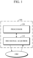
- FIG. 1 is a block diagram illustrating an apparatus for estimating bio-information according to one exemplary embodiment.
- the apparatus 100 for estimating bio-information of the present exemplary embodiment may be implemented as a hardware device to be mounted in a terminal, such as a smartphone, a tablet personal computer (PC), a desktop PC, a notebook PC, or the like, or an independent hardware device.
- a terminal such as a smartphone, a tablet personal computer (PC), a desktop PC, a notebook PC, or the like
- an independent hardware device When the apparatus 100 is implemented as an independent hardware device, the apparatus 100 may have the form of a wearable device that a user (e.g., an object OBJ) can easily measure bio-information while carrying the device.
- a wearable device e.g., an object OBJ
- the hardware device may be implemented as a wearable device of a wristwatch type, a bracelet type, a wristband type, a ring type, a glass type, or a hairband type.
- the type of wearable device is not limited to the above examples, and the wearable device may be modified according to various purposes, for example, it may be manufactured as a fixed type for utilizing bio-information in a medical institution for measurement and analysis.
- the apparatus 100 for estimating bio-information includes a bio-signal acquirer 110 and a processor 120.
- the bio-signal acquirer 110 acquires a bio-signal from an object OBJ as shown in FIG. 1 and transmit the acquired bio-signal to the processor 120.
- the bio-signal is a photoplethysmogram (PPG) signal (hereafter referred to as a "pulse wave signal").
- PPG photoplethysmogram
- the bio-signal is not limited thereto and may include various bio-signals, such as an electrocardiography (ECG) signal, a PPG signal, an electromyography (EMG) signal, and the like, which can be modeled by a plurality of waveform components.
- the bio-signal acquirer includes a spectrometer or a PPG sensor configured to measure a PPG signal.
- the PPG sensor includes a light source configured to emit light to the object OBJ and a detector configured to measure a PPG signal by detecting light scattered or reflected from tissues of the irradiated object OBJ.
- the light source includes at least one of a light emitting diode, a laser diode, and a phosphor, but is not limited thereto.
- the detector includes a photodiode.
- the processor 120 may generate a control signal to drive the bio-signal acquirer 110.
- the bio-signal acquirer 110 may emit a light to the object OBJ and receive the light that is reflected from the OBJ.
- the bio-signal acquire 110 may acquire a pulse wave signal (i.e., a PPG signal) from the received light.
- the object is a living body which can be in touch with or adjacent to the PPG sensor and may be a part of a human body which is easy to measure a PPG signal.
- the object OBJ may be an area of a wrist surface adjacent to a radial artery and may include an upper part of a wrist where venous blood or capillary blood passes.
- the object OBJ is not limited to the above examples, and may be a peripheral region of a human body, such as a finger, a toe, or the like, which is a region having a high blood vessel density in the human body.
- the bio-signal acquirer 110 may perform preprocessing on the bio-signal, such as filtering for removing noise from the acquired bio-signal, amplification of the bio-signal, or converting the bio-signal into a digital signal.
- the processor 120 may generate a control signal to control the bio-signal acquirer 110, and transmit the control signal to the bio-signal acquirer 110.
- the processor 120 may receive the bio-signal from the bio-signal acquirer 110 and acquire bio-information by analyzing the received bio-signal.
- the bio-information may include a blood pressure, vascular age, arterial stiffness, aortic pressure waveform, stress index and fatigue, but is not limited thereto.
- the processor 120 may extract features necessary for bio-information estimation by analyzing a waveform of the received bio-signal. To this end, the processor 120 may extract a plurality of characteristic points from the received bio-signal and extract the features using the extracted characteristic points.
- the processor 120 may extract points associated with a plurality of component pulses constituting the waveform of the entire bio-signal as the characteristic points.
- the processor 120 may calculate internally dividing points of characteristic points.
- the processor 120 may use any one or any combination of the characteristic points and the internally dividing points to extract features for bio-information estimation.
- the internally dividing point is calculated from the characteristic points initially extracted from the bio-signal and is used along with the characteristic points to extract additional features that may be used to perform bio-information estimation. Accordingly, it may be possible to obtain a more accurate feature even when the initially extracted characteristic points are extracted from an instable waveform under a non-ideal environment, such as motion noise or sleep.
- FIG. 2 is a block diagram illustrating an apparatus for estimating bio-information according to another exemplary embodiment.
- an apparatus 200 for estimating bio-information includes a bio-signal acquirer 110, a processor 120, a communication interface 210, an output interface 220, and a storage 230.
- the bio-signal acquirer 110 may acquire a bio-signal of an object from an external device 250.
- the bio-signal acquirer 110 may acquire a bio-signal from the external device 250 through the communication interface 210 without being equipped with a bio-signal measurement sensor, such as a PPG sensor.
- the bio-signal acquirer 110 may selectively use a method of acquiring a bio-signal from the external device 250 under the control of the processor 120 or acquiring a bio-signal by directly driving the bio-signal measurement sensor.
- the bio-signal acquirer 110 may perform a preprocessing operation to remove noise from the bio-signal received from the external device 250 and convert the bio-signal into a digital signal, and then may transmit the processed bio-signal to the processor 120.
- the processor 120 may generate a control signal to control the bio-signal acquirer 110 in order to acquire the bio-signal.
- the processor 120 may control the communication interface 210 to be connected to the external device 250.
- the apparatus 200 may be connected to the external device 250 through the communication interface 213, using access information of the external device 250 that is included in the control signal. Once the apparatus 200 is connected to the external device 250, the apparatus 200 210 may receive the bio-signal from the external device 250 and then transmit the bio-signal to the bio-signal acquirer 110, through the communication interface 210.
- the external device 250 may include a bio-signal measurement sensor to directly measure a bio-signal from the object, or may be a device that receives a bio-signal from a bio-signal measurement device and stores the received bio-signal.
- the communication technology may include a Bluetooth communication, a Bluetooth low energy communication, a near field communication (NFC), a wireless local area network (WLAN) communication, a ZigBee communication, an infrared data association (IrDA) communication, a Wi-Fi direction communication, an ultra-wideband (UWB) communication, Ant+ communication , a Wi-Fi communication, and a mobile communication technology, but is not limited thereto.
- the processor 120 may analyze the bio-signal to extract characteristic points and extract features that may be necessary for bio-signal estimation using the extracted characteristic points. In this case, when a waveform of the bio-signal exhibits a non-ideal and unstable form, the processor 120 may calculate internally dividing points using the extracted characteristic points and use the calculated internally dividing points along with the characteristic points to extract features.
- the processor 120 may estimate bio-information using the extracted feature.
- the bio-information may be estimated using a previously constructed bio-information estimation model.
- the output interface 220 may output and provide the acquired bio-signal information and various processing results of the processor 120.
- the output interface 220 may provide the information to the user through various visual/non-visual methods using a display module, a speaker, and a haptic device mounted in the device.
- the output interface 220 may output the estimated blood pressure to the user using various visual methods, such as a color, a thickness of a line, a font, and the like, based on whether the estimated blood pressure is within or out of a normal range.
- the estimated blood pressure may be output by voice or through a non-visual method in which vibration or tactile sensation is changed according to the abnormality of the blood pressure.
- the user may be warned or advised about actions to be taken by providing, for example, cautionary food information or information about a hospital to be reserved.
- the storage 230 may store various pieces of reference information required for bio-information estimation, the obtained bio-signal, the extracted characteristic points and internally dividing points, the extracted features, bio-information estimation results, and the like.
- the various pieces of reference information required for bio-information estimation may include user information, such as an age, sex, occupation, current health status, and the like, and the bio-information estimation model information, but is not limited thereto.
- the processor 120 may request the external device 250 to estimate bio-information by transmitting information about at least one of the extracted characteristic points, the internally dividing points, and the extracted feature to the external device 250.
- the external device 250 may request the bio-information estimation by transmitting the characteristic points, internally dividing points, or feature information.
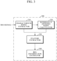
- FIG. 3 is a block diagram illustrating the processor according to the exemplary embodiments of FIGS. 1 and 2 .
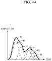
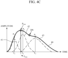
- FIGS. 4A to 4C are diagrams for describing an exemplary embodiment in which characteristic points are extracted from a bio-signal.
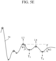
- FIGS. 5A to 5E are diagrams for describing an exemplary embodiment in which internal dividing points are calculated using the characteristic points of the bio-signal.
- the pulse wave signal acquired from the object may be a summation of a propagation wave propagating from the heart to peripheral parts of a body and reflection waves returning from the peripheral parts of the body.
- FIG. 4A illustrates a pulse wave signal 40 which is a summation of five component pulses 41, 42, 43, 44, and 45.
- time and amplitude information may be extracted as characteristic points and the extracted characteristic points are appropriately combined, a feature with high correlation with blood pressure may be extracted.
- up to third component pulses are mainly used to estimate blood pressure. Subsequent pulses may not be observed because it may be difficult to detect the subsequent pulses due to noise. Also, the subsequent pulses may have low correlation with blood pressure estimation.
- FIG. 4B illustrates an example of extracting points associated with component pulses as characteristic points from a pulse wave signal using a second derivative signal of a bio-signal.
- the characteristic point extractor 310 may derive a second derivative signal by differentiating the bio-signal as shown in (2) SECOND DERIVATIVE SIGNAL, search for local minimum points from the derived second derivate signal as shown in (3) TIME INFORMATION OF LOCAL MINIMUM POINTS, and extract time points T 1 ,T 2 , and T 3 corresponding to the local minimum points as the characteristic points, as shown in (4) AMPLITUDE INFORMATION OF BIO-SIGNAL.
- the characteristic point extractor 310 may extract, from the entire bio-signal, amplitudes P 1 , P 2 , and P 3 corresponding to the time points T 1 ,T 2 , and T 3 extracted from the derivative signal as characteristic points.
- the local minimum point may refer to a specific point of a part of the second derivative signal where the signal decreases and increases again, that is, a point having a downwardly convex shape.
- the local minimum point may refer to a point of a graph where the graph changes from increasing to decreasing, or the smallest value of the graph within a given range.
- the characteristic point extractor 310 may extract a point in a predetermined region of the bio-signal 40 where the amplitude is the maximum as an additional characteristic point, as shown in FIG. 4C .
- the predetermined region of the bio-signal 40 refers to a systolic phase of the blood pressure from the beginning of the bio-signal 40 to the point of the dicrotic notch (DN).
- the dicrotic notch may refer to an acute drop followed by a rise in blood pressure pulse curves, which appears subsequent to a systolic peak.
- a position where the bio-signal 40 is curved or bulged downward between time points T 2 and T 3 may correspond to the dicrotic notch.
- the characteristic point extractor 310 may extract time points T 1 ,T 2 , and T 3 and amplitudes P 1 , P 2 , and P 3 from each of the three component pulses 41, 42, and 43 constituting the bio-signal 40 as characteristic points, and extract a time point T max and an amplitude P max at a point where the systolic phase of the blood pressure as additional characteristic points.
- the characteristic point extractor 310 may derive a second derivative signal and extract characteristic points by searching for local minimum points of the second derivative signal.
- the characteristic point extractor 310 may extract an area S area of the bio-signal waveform, for example, the whole area or a partial area as characteristic points.
- the partial area may mean the area of the bio-signal waveform corresponding to a time region from the beginning to a predetermined ratio (e.g., 70%) based on a time axis of the bio-signal waveform.
- Examples of the characteristic point extraction of the bio-signal are not limited to the above description, and the characteristic points may be extracted using other various methods.
- the feature extractor 330 may combine the extracted characteristic points to extract features for bio-information estimation.
- the internally dividing point calculator 320 may calculate internally dividing points using the characteristic points extracted by the characteristic point extractor 310, thereby allowing the calculated internally dividing points to be used along with the extracted characteristic points in feature extraction.
- FIGS. 5A and 5B are diagrams illustrating examples in which the internally dividing point calculator 320 calculates an internally dividing point in a systolic region.
- the systolic region may refer to a region between the beginning of an acquired pulse wave signal 51 and the dicrotic notch (DN).
- the internally dividing point calculator 320 may calculate an internally dividing point (T sys , P sys ) between two characteristic points (T 1 , P 1 ) and (T 2 , P 2 ) using the two characteristic points (T 1 , P 1 ) and (T 2 , P 2 ) associated with a component pulse extracted from the systolic region by the characteristic point extractor 310.
- the internally dividing point calculator 320 may apply weights a and b respectively to each time value T 1 and T 2 of the two characteristic points (T 1 , P 1 ) and (T 2 , P 2 ), and calculate the internally dividing point T sys using each of the time values aT 1 , bT 2 to which the weights are applied.
- the internally dividing point calculator 320 may obtain the internally dividing point T sys by summing the time values aT 1 and bT 2 to which the weights are applied and dividing the sum of the time values by the sum of the weights.
- the exemplary embodiment is not limited to the above examples, and the weight to be applied to each of the time points may be an arbitrary constant predefined through a preprocessing operation. As such, when the internally dividing point time T sys is determined, it is possible to extract the amplitude P sys at a point of the bio-signal corresponding to T sys .
- the exemplary embodiment of FIG. 5B is useful when a waveform of the bio-signal 51 is not ideal and exhibits instability.
- a waveform component corresponding to the second characteristic point (T 2 , P 2 ) may not be accurately observed.
- a characteristic point (T max , P max ) at which the amplitude is the maximum in the systolic region may be used to obtain an internally dividing point (T sys , P sys ) robust to the abnormal waveform.
- FIGS. 5C to 5E are diagrams for describing an exemplary embodiment in which an internally dividing point in the diastolic region is calculated.
- the diastolic region may refer to a region of a bio-signal after dicrotic notch (DN).
- the characteristic point extractor 310 may extract a point (T 3 , P 3 ), which is a point associated with the third component pulse, as a representative characteristic point in the diastolic region of a pulse wave signal 52.
- This characteristic point increases in instability relative to a characteristic point extracted from the diastolic region due to various noises generated.
- the internally dividing point calculator 320 may calculate an internally dividing point by utilizing a characteristic point of another component pulse in the systolic region.
- a characteristic point (T 4 , P 4 ) associated with a waveform component having an amplitude greater than an amplitude of the amplitude P 3 for example, a waveform component of the fourth component pulse in the diastolic region may be extracted in the case of a specific bio-signal waveform.
- the characteristic point (T 3 , P 3 ) associated with the third component pulse may not be given great significance.
- the internally dividing point calculator 320 may determine whether a preset condition of calculating the internally dividing point in the diastolic region is satisfied, and, when the condition is satisfied, may calculate the internally dividing point. In this case, the condition for calculating the internally dividing point in the diastolic region may be satisfied when the value of P 3 is smaller than the value of P 4 . When it is determined that the value of P 3 is greater than the value of P 4 , the characteristic point (T 3 , P 3 ) extracted from the third component pulse may be used as is.
- condition for calculating the internally dividing point is not limited to the above description, and the condition may include a case where a difference between P 3 and P 4 is not greater than an arbitrary number, a case where a difference between P 3 and P 4 is greater than an arbitrary number, or the like.
- the internally dividing point calculator 320 may calculate the internally dividing point based on an n-order derivative signal of the bio-signal in the diastolic region.
- the characteristic point extractor 310 may search for local minimum points of a second derivative signal by second order differentiating the bio-signal and extract characteristic points associated with component pulses, as described above. In this case, if the bio-signal has been acquired in a non-ideal environment and thus the waveform of the bio-signal is unstable, the second derivative signal may also fluctuate unstably.
- the local minimum point of the second derivative signal corresponding to the representative characteristic point (T 3 , P 3 ) of the diastolic region does not appear at the physiologically correct position, and the local minimum point of the second derivative signal may unsteadily fluctuate back and forth around the corresponding position.
- the inte rnally dividing point calculator 320 may calculate an internally dividing point of characteristic points extracted from two local minimum points of the second derivative signal in order to alleviate the instability of the second derivative signal.
- the internally dividing point calculator 320 may apply a weight to each of the time values of the characteristic points based on a difference between the amplitude of each of the local minimum points of the second derivative signal and the amplitude at a predetermined point of the second derivative signal, and calculate the internally dividing point using each of the time values to which the weights are applied, as described above.
- a difference W 1 between the amplitude of T 3 , which is a local minimum point of a diastolic region of a second derivative signal 54, and the amplitude of a local maximum point L 4 , which appears immediately before T 4 may be determined as a weight to be applied to the time value T 3 of a characteristic point in the diastolic region.
- a difference W 2 between the amplitude of T 4 , which is a local minimum point, and the amplitude of L 4 , which is a local maximum point may be determined as a weight of the time value T 4 of a characteristic point of the diastolic region.
- the time value T 3 may be referred to as a third local minimum point given that the time value T 3 is a local minimum point that thirdly appears in the diastolic region of the second derivative signal 54.
- the time value T 4 may be referred to as a fourth local minimum point given that the time value T 4 is a local minimum point that fourthly appears in the diastolic region of the second derivative signal 54.
- FIG. 5E shows an example in which differences between the amplitude of T 3 and the amplitude of L 3 and between the amplitude of T 4 and the amplitude of L 3 are determined as weights W 1 and W 2 to be applied respectively to time values T3 and T4 of characteristic points of the diastolic region.
- the internally dividing point calculator 320 may determine whether a condition for calculating an internally dividing point is satisfied based on at least one of the weights W 1 and W 2 , which are obtained based on the second derivative signal, and when the condition is satisfied, may calculate the internally dividing point. For example, only when the weight W 1 to be applied to the first characteristic point (T 3 , P 3 ) in the diastolic region is smaller than a predetermined threshold, the internally dividing point may be calculated. If the weight W 1 is greater than or equal to the predetermined threshold, the first characteristic point (T 3 , P 3 ) may be used as is without the weight W 1 being applied.
- condition for calculating the internally dividing point may include various conditions, such as a case where the W 2 to be applied to the second characteristic point (T 4 , P 4 ) in the diastolic region is greater than a predetermined threshold.
- the feature extractor 330 may determine information to be used in feature extraction among the obtained characteristic points and internally dividing points, and extract features necessary for bio-information extraction by combining the determined information.
- T 1 , P 1 ), (T 3 , P 3 ), (T 4 , P 4 ), (T max , P max ), and S are extracted by the characteristic point extractor 310.
- an internally dividing point (T sys , P sys ) between the characteristic points (T 1 , P 1 ) and (T max , P max ) and an internally dividing point (T dia , P dia ) between the characteristic points (T 3 , P 3 ) and (T 4 , P 4 ) are calculated.
- the feature extractor 330 may determine the calculated internally dividing points (T sys , P sys ) and (T dia , P dia ), the characteristic point (T max , P max ), and S area as information to be used in feature extraction. In addition, the feature extractor 330 acquires two features f 1 and f 2 as shown in Equation 5 below by combining the determined information.
- the first feature f 1 is a feature related to the cardiac output, and it may further include, such as, P max /P area , P max /P 3 , P sys /P 3 , P 1 /P 3 , P 2 /P 3 , 1/T period , or the like.
- the second feature f 2 is a feature related to the total peripheral vascular resistance, and it may further include 1/(T 3 -T sys ), 1/(T 3 -T max ), 1/(T 3 -T 1 ), 1/(T 3 -T 2 ), P 3 /P 1 , P 2 /P 1 , or the like.
- P area denotes the sum of amplitudes of the bio-signal for a predefined time interval (e.g. between time 0 and ⁇ dur *T period ).
- T period denotes a period of the bio-signal.
- ⁇ dur denotes a predefined setting factor (0 ⁇ ⁇ dur ⁇ 1) (e.g., 0.7).
- the bio-information estimator 340 estimates bio-information using the extracted features.
- Blood pressure is estimated by applying the features extracted as shown in the above Equation 5 to a blood pressure estimation equation as shown in Equation 6 below.
- BP A f 1 + wf 2 + B
- BP denotes an estimated blood pressure
- A, w, and B denote arbitrary coefficients.
- FIG. 6A is a flowchart illustrating a method of estimating bio-information according to one exemplary embodiment.
- FIG. 6A shows an exemplary embodiment of a method of estimating bio-information which is performed by the apparatus 100 for estimating bio-information according to the exemplary embodiment of FIG. 1 , which has been described in detail with reference to FIGS. 1 to 5E , and thus the method will be described in brief to avoid unnecessary repetition.
- the apparatus 100 for estimating bio-information receives a request for bio-information estimation, in operation 610.
- the apparatus 100 may provide an interface to perform various interactions with a user.
- the user may request the bio-information estimation through the interface provided by the apparatus 100.
- the apparatus 100 may receive a request for bio-information estimation from an external device.
- the request for bio-information estimation received from the external device may include a request for providing a bio-information estimation result.
- the request for bio-information estimation may include a request for providing characteristic point or feature information.
- the external device may include a smartphone or a tablet PC that the user carries, and the user may control the apparatus 100 through a portable device having superior interface performance and computing performance to those of the apparatus 100 for bio-information estimation.
- the apparatus 100 acquires a bio-signal for bio-information estimation, in operation 620.
- the apparatus 100 may control a bio-signal measurement sensor (e.g., a PPG sensor) to measure a pulse wave signal, and acquire a pulse wave signal from an object.
- a bio-signal measurement sensor e.g., a PPG sensor
- the apparatus 100 may receive a bio-signal from an external bio-signal measurement device.
- a plurality of characteristic points may be extracted from the acquired bio-signal, in operation 630.
- the apparatus 100 may extract points associated with component pulses constituting the acquired bio-signal as the characteristic points.
- the apparatus 100 may acquire a second derivative signal of a pulse wave signal acquired for estimating blood pressure, and extract information about time and amplitude of a local minimum point of the second derivative signal as a characteristic point associated with a component pulse.
- the apparatus 100 may extract time and amplitude information at a point where the amplitude is the maximum in a systolic phase of blood pressure as an additional characteristic point in order to compensate the case where the pulse wave signal is unstable due to noise, motion, or the like.
- the apparatus 100 may extract the whole area or a partial area of the pulse wave signal as an additional characteristic point.
- the apparatus 100 may calculate an internally dividing point for each of the systolic region and the diastolic region of the pulse wave signal. Two time values extracted from the pulse wave signal may be given weights and an internally dividing point may be calculated using the time values to which the weights are applied. In this case, the weights may be determined based on the amplitude values of two characteristic points. For example, the internally dividing point may be calculated by dividing the sum of the time values to which the weights are applied by the sum of the weights. Meanwhile, when the plurality of characteristic points are extracted, the apparatus 100 may check various preset conditions for calculating an internally dividing point, and may use the extracted characteristic points intact when the conditions are not satisfied.
- the apparatus 100 extracts features necessary for bio-information estimation using the extracted characteristic points and internally dividing points, in operation 650.
- the features necessary for bio-information estimation may be extracted by combining two or more characteristic points and internally dividing points as shown in Equation 5.
- the apparatus 100 may extract characteristic points (T 1 , P 1 ), (T 2 , P 2 ), and (T max , P max ) from the systolic region of the pulse wave signal, in operation 630a.
- the apparatus 10 may calculate a first internally dividing point T sys1 according to equation 1 in operation 640a, and may calculate a second internally dividing point T sys2 according to equation 2 in operation 640b.
- the apparatus 100 may perform either operation 640a or operation 640b, or both of the operations 640a and 640b.
- the apparatus 100 may extract features based on the first internally dividing point T sys1 and the second internally dividing point T sys2 in operations 650a and 650b, respectively.
- the apparatus 100 may extract characteristic points (T 3 , P 3 ) and (T 4 , P 4 ) from the diastolic region of the pulse wave signal, in operation 630b. If the apparatus 100 determines that the amplitude P 4 is greater than the amplitude P 3 in operation 640c, the apparatus 100 may calculate a first internally dividing point T dia1 for the diastolic region according to Equation 3, in operation 640e, and extract a feature based on T dia1 in operation 650d. On the other hand, if the apparatus 100 determines that the amplitude P 4 is less than or equal to the amplitude P 3 in operation 640c, the apparatus 100 may extract a feature based on the characteristic point (T 3 , P 3 ).
- the apparatus 100 may determine whether a difference W 1 between the amplitude at a local minimum point T 3 of the second derivative signal 54 and the amplitude at a local maximum point L 4 immediately before T 4 is less than a predetermined threshold, in operation 640d.
- the different W1 may correspond to the difference between the amplitude at T 3 and the amplitude at a local maximum point L 3 immediately before T 4 .
- the apparatus 100 may calculate a second internally dividing point T dia2 for the diastolic region according to Equation 4, and then in operation 650e, the apparatus 100 may extract a feature based on the second internally dividing point T dia2 .
- the apparatus 100 may extract a feature based on the characteristic point (T 3 , P 3 ) instead of the second internally dividing point T dia2 in operation 650f
- Operations 630a, 640a, 640b, 650a, and 650b shown in FIG. 6B , and operations 630b, 640c-640f, and 650d-650f shown in FIG. 6c may be performed in parallel or in sequence.
- the apparatus 100 estimates bio-information using the extracted features, in operation 660.
- a bio-information estimation model may be constructed in advance.
- the bio-information estimation model may be a mathematical equation as shown in Equation 6.
- the apparatus 100 may estimate the bio-information by applying the extracted feature information to the bio-information estimation model.
- the apparatus 100 provides a bio-information estimation result to the user, in operation 670.
- the apparatus 100 may provide the estimated bio-information to the user using various visual/non-visual methods.
- the apparatus 100 may determine the user's health status based on the estimated bio-information, and provide warning or an advice on actions to be taken to the user according to the determination result.
- FIGS. 7A to 7D are diagrams for describing a wearable device according to one exemplary embodiment.
- Various exemplary embodiments of the above-described apparatus for estimating bio-information may be mounted in a smartwatch or smart band-type wearable device worn on a wrist.
- this is merely an example for convenience of description, and the exemplary embodiments should not be construed as being limited to being applied to a smart watch or smart band-type wearable device.
- a wearable device 700 includes a device main body 710 and a strap 720.
- the strap 720 may be configured to be flexible and bent in such a manner that is wrapped around the wrist of the user or separated from the wrist.
- the strap 720 may be configured in a non-separable band form.
- the strap 720 may be filled with air or an air bag so as to have elasticity according to a change in pressure applied to the wrist, and may transmit a pressure change of the wrist to the main body 710.
- a battery may be equipped in the main body 710 or the strap 720 to supply power to the wearable device.
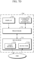
- the wearable device 700 may include, inside the main body 710, a measurer 711 configured to measure a bio-signal by emitting light to an object OBJ and detecting scattered light returning from the object OBJ, and a processor 712 configured to detect bio-information of the user using the bio-signal measured by the measurer 711.
- the measurer 711 may be mounted on a lower portion of the main body 710, that is, a portion that comes in contact with the object OBJ, for example, the user's wrist, and may include a light source 711A configured to emit light to the object OBJ and a detector 711B configured to detect light emitted from the object OBJ according to a control signal of the processor 712.
- the measurer 711 may further include a contact pressure sensor configured to measure a contact pressure of the object OBJ.
- the contact pressure sensor may measure the contact pressure of the object OBJ transferred to the main body 710 through the strap 720 that secures the main body to the object OBJ in a manner that is wrapped around the wrist.
- the processor 712 may generate the control signal to control the measurer 711.
- the processor 712 may receive bio-signal data measured by the measurer 711 and estimate bio-information using the bio-signal data.
- the processor 712 may extract a plurality of characteristic points from the bio-signal as described above.
- the plurality of characteristic points may be extracted from points associated with component pulses of the bio-signal.
- a point where the amplitude is the maximum within a predetermined region of the bio-signal or an area of the bio-signal may be extracted as characteristic points.
- the processor 712 may calculate internally dividing points of two or more characteristic points and extract features using the calculated internally dividing points and the characteristic points.
- the processor 712 may determine characteristic points to be used to calculate the internally dividing points according to a preset criterion for calculating the internally dividing points, apply weights to time values of two or more determined characteristic points, and calculate the internally dividing points based on the time values to which the weights are applied.
- the weights respectively applied to each of the time values may be determined based on amplitude values of each of the two or more determined characteristic points.
- the processor 712 may guide the user to change the contact pressure applied to the wrist based on the measured contact pressure signal.
- the processor 712 may manage estimated bio-information, for example, blood pressure history information, bio-information used to measure various blood pressures, and component pulses decomposed from the bio-information in a storage device. Also, the processor 712 may generate additional information, such as alarm or warning information related to estimated bio-information, a change in health status, and the like, which is necessary for user's healthcare and manage the generated information in the storage device.
- estimated bio-information for example, blood pressure history information, bio-information used to measure various blood pressures, and component pulses decomposed from the bio-information in a storage device.
- additional information such as alarm or warning information related to estimated bio-information, a change in health status, and the like, which is necessary for user's healthcare and manage the generated information in the storage device.
- the wearable device 700 may further include an operator 715 and a display 714, which are mounted in the main body 710.
- the operator 715 may receive a control instruction of the user, transmit the control instruction to the processor 712, and include a power button to enable the user to input an instruction for power on/off of the wearable device 700.
- the display 714 may provide a variety of information related to the detected bio-information under the control of the processor 712.
- the display 714 may display additional information, such as measured blood pressure, alarm, or warning information, to the user in various visual/non-visual ways.
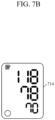
- the display 714 may display estimated blood pressure information as shown in FIG. 7B .
- the display 714 may display the detailed information as shown in FIG. 7C .
- the display 714 may include a first area 714b and a second area 714a.
- the estimated blood pressure information may be displayed in the first area 714b, as shown in FIG. 7B .
- the change in blood pressure may be displayed in the form of a graph.
- the display 714 may display a mark M that indicates currently selected blood pressure information I in the first area 714b.
- the mark M is shown as a vertical line, but is not limited thereto, and the mark M may be displayed in various forms, such as a polygon, such as a circle, a rectangle, and the like, and an arrow indicating a position of the selected blood pressure information.
- the user may touch and select desired blood pressure information or select the desired blood pressure information by moving the graph to the left and right to align the desired blood pressure information to the mark M.
- blood pressure information, extracted feature information, and the like may be displayed near the selected blood pressure information.
- the display 714 may display a bio-signal used to estimate the selected blood pressure information I in response to the user's selection, and component pulses constituting the bio-signal in the second area 714a.
- extracted characteristic points may be displayed on the bio-signal shown in the second area 714a.
- the main body 710 may further include a communication interface 713 in an internal space so as to communicate with an external device, such as a portable terminal of the user.
- the communication interface 713 may communicate with the external device of a user which has a relatively better computing performance and transmit and receive necessary information under the control of the processor 712. For example, the communication interface 713 may receive a request for estimating bio-information from the user's portable terminal. In addition, the communication interface 713 may transmit extracted characteristic points or feature information to the external device to request estimation of bio-information. Further, the communication interface 713 may transmit a bio-information estimation result to the external device so as to be displayed to the user or to be utilized for various purposes, such as bio-information history management and disease research.
- an exemplary embodiment can be embodied as computer-readable code on a computer-readable recording medium.
- the computer-readable recording medium is any data storage device that can store data that can be thereafter read by a computer system. Examples of the computer-readable recording medium include read-only memory (ROM), random-access memory (RAM), CD-ROMs, magnetic tapes, floppy disks, and optical data storage devices.
- the computer-readable recording medium can also be distributed over network-coupled computer systems so that the computer-readable code is stored and executed in a distributed fashion.
- an exemplary embodiment may be written as a computer program transmitted over a computer-readable transmission medium, such as a carrier wave, and received and implemented in general-use or special-purpose digital computers that execute the programs.
- one or more units of the above-described apparatuses and devices can include circuitry, a processor, a microprocessor, etc., and may execute a computer program stored in a computer-readable medium.
Landscapes
- Health & Medical Sciences (AREA)
- Life Sciences & Earth Sciences (AREA)
- Engineering & Computer Science (AREA)
- Public Health (AREA)
- Medical Informatics (AREA)
- Biomedical Technology (AREA)
- Pathology (AREA)
- Cardiology (AREA)
- General Health & Medical Sciences (AREA)
- Animal Behavior & Ethology (AREA)
- Physics & Mathematics (AREA)
- Heart & Thoracic Surgery (AREA)
- Molecular Biology (AREA)
- Surgery (AREA)
- Veterinary Medicine (AREA)
- Biophysics (AREA)
- Physiology (AREA)
- Vascular Medicine (AREA)
- Psychiatry (AREA)
- Artificial Intelligence (AREA)
- Signal Processing (AREA)
- Computer Vision & Pattern Recognition (AREA)
- Data Mining & Analysis (AREA)
- Databases & Information Systems (AREA)
- Epidemiology (AREA)
- Primary Health Care (AREA)
- Hospice & Palliative Care (AREA)
- Psychology (AREA)
- Social Psychology (AREA)
- Educational Technology (AREA)
- Developmental Disabilities (AREA)
- Child & Adolescent Psychology (AREA)
- Nuclear Medicine, Radiotherapy & Molecular Imaging (AREA)
- Radiology & Medical Imaging (AREA)
- Measuring Pulse, Heart Rate, Blood Pressure Or Blood Flow (AREA)
Claims (7)
- Vorrichtung (100; 200) zum Schätzen von Bioinformationen, wobei die Vorrichtung umfasst:einen Biosignalerfasser (110), ausgebildet zum Erfassen eines Biosignals (40), das ein Photoplethysmogramm-(PPG-)Signal ist, wobei der Biosignalerfasser (110) einen PPG-Sensor, ausgebildet zum Messen des PPG-Signals durch Detektieren von von einem Objekt reflektierten oder gestreuten Licht, umfasst; undeinen Prozessor (120), ausgebildet zum Extrahieren einer Vielzahl von charakteristischen Punkten aus dem Biosignal (40), Bestimmen von internen Teilungspunkten der Vielzahl von charakteristischen Punkten und Extrahieren von Merkmalswerten aus dem Biosignal (40) basierend auf den internen Teilungspunkten, um eine Bioinformationsschätzung durchzuführen,wobei der Prozessor einen Extrahierer für charakteristische Punkte, ausgebildet zum Extrahieren eines ersten charakteristischen Punkts (T1, P1), verbunden mit einem ersten Komponentenimpuls des Biosignals, eines dritten charakteristischen Punkts (T3, P3), verbunden mit einem dritten Komponentenimpuls des Biosignals, und eines vierten charakteristischen Punkts (T4, P4), verbunden mit einem vierten Komponentenimpuls des Biosignals, eines zweiten charakteristischen Punkts (Tmax, Pmax), an dem eine Amplitude einen Maximalwert in einem systolischen Bereich des Biosignals aufweist, und einer Fläche (Sarea) des Biosignals als die mehreren charakteristischen Punkte, umfasst,wobei der Extrahierer für charakteristische Punkte ferner zum Bestimmen von lokalen Minima in einem zweiten abgeleiteten Signal des Biosignals als die mit den Komponentenimpulsen verbundenen Punkte ausgebildet ist,wobei der Prozessor (120) einen Internteilungspunkt-Rechner (320), ausgebildet zum Anwenden von Gewichten jeweils auf Zeitwerte der Vielzahl von charakteristischen Punkten und Berechnen der internen Teilungspunkte der Vielzahl von charakteristischen Punkten basierend auf den Zeitwerten, auf welche die Gewichte angewendet werden, umfasst,wobei der Internteilungspunkt-Rechner (320) zum Berechnen eines ersten internen Teilungspunkts (Tsys, Psys) zwischen dem ersten charakteristischen Punkt (T1, P1) und dem zweiten charakteristischen Punkt (Tmax, Pmax) und eines zweiten internen Teilungspunkts (Tdia, Pdia) zwischen dem dritten charakteristischen Punkt (T3, P3) und dem vierten charakteristischen Punkt (T4, P4) ausgebildet ist,wobei der Prozessor ferner einen Merkmalsextrahierer, ausgebildet zum Extrahieren eines ersten Merkmalswerts f1 basierend auf einem Verhältnis der Fläche des Biosignals zu einem Amplitudenwert an dem Punkt, an dem eine Amplitude den Maximalwert im systolischen Bereich des Biosignals aufweist, und zum Extrahieren eines zweiten Merkmalswerts f2 basierend auf einem Kehrwert eines Unterschieds im Zeitwert zwischen dem ersten internen Teilungspunkt (Tsys, Psys), erfasst aus dem systolischen Bereich, und dem zweiten internen Teilungspunkt (Tdia, Pdia), erfasst aus einem diastolischen Bereich des Biosignals, wobei sich der erste Merkmalswert auf ein Herzzeitvolumen bezieht und der zweite Merkmalswert auf einen gesamten peripheren Gefäßwiderstand bezieht, umfasst, undwobei der Prozessor (120) einen Bioinformationsschätzer (340), ausgebildet zum Schätzen von Bioinformationen, die den Blutdruck darstellen, basierend auf der Gleichung BP = A(f1 + w · f2) + B, wobei BP den Blutdruck bezeichnet, f 1 den ersten extrahierten Merkmalswert, f2 den zweiten extrahierten Merkmalswert und A, w und B Koeffizienten bezeichnen, umfasst.
- Vorrichtung nach Anspruch 1, wobei der Internteilungspunkt-Rechner ferner zum Berechnen der internen Teilungspunkte der Vielzahl von charakteristischen Punkten basierend auf einer Summe der Gewichte ausgebildet ist.
- Vorrichtung nach Anspruch 1 oder Anspruch 2, wobei der Internteilungspunkt-Rechner ferner zum Anwenden der Gewichte jeweils auf die Zeitwerte basierend auf den Amplitudenwerten der Vielzahl von charakteristischen Punkten ausgebildet ist; und/oder
wobei der Internteilungspunkt-Rechner ferner zum Berechnen der Gewichte basierend auf Unterschieden zwischen ersten Amplituden an einer Vielzahl von Punkten in einem abgeleiteten Signal des Biosignals und einer zweiten Amplitude an einem vorbestimmten Punkt im abgeleiteten Signal ausgebildet ist und wobei die Vielzahl von Punkten im abgeleiteten Signal der Vielzahl von aus dem Biosignal extrahierten charakteristischen Punkten entspricht. - Vorrichtung nach einem der Ansprüche 1 bis 3, wobei der PPG-Sensor zum Ausstrahlen von Licht auf das Objekt ausgebildet ist.
- Vorrichtung nach einem der Ansprüche 1 bis 4, wobei der Biosignalerfasser eine Lichtquelle, ausgebildet zum Ausstrahlen eines Lichts auf ein Objekt, und einen Detektor, ausgebildet zum Detektieren des vom Objekt gestreuten oder reflektierten Lichts, umfasst, und
wobei der Biosignalerfasser das Biosignal aus dem vom Detektor detektierten Licht erfasst. - Verfahren zum Schätzen von Bioinformationen, wobei das Verfahren umfasst:Messen eines Biosignals (40), das ein Photoplethysmogramm-(PPG-)Signal ist, durch einen PPG-Sensor (620) durch Detektieren von von einem Objekt reflektierten oder gestreuten Licht;Extrahieren (630) einer Vielzahl von charakteristischen Punkten aus dem Biosignal (40),wobei die Vielzahl von charakteristischen Punkte einen ersten charakteristischen Punkt (T1, P1), verbunden mit einem ersten Komponentenimpuls des Biosignals, einen dritten charakteristischen Punkt (T3, P3), verbunden mit einem dritten Komponentenimpuls des Biosignals, und einen vierten charakteristischen Punkt (T4, P4), verbunden mit einem vierten Komponentenimpuls des Biosignals, einen zweiten charakteristischen Punkt (Tmax, Pmax), an dem eine Amplitude einen Maximalwert in einem systolischen Bereich des Biosignals aufweist, und eine Fläche (Sarea) des Biosignals umfasst;wobei das Extrahieren der Vielzahl von charakteristischen Punkten das Bestimmen von lokalen Minima in einem zweiten abgeleiteten Signal des Biosignals als die mit den Komponentenimpulsen verbundenen Punkte umfasst;Bestimmen (640) von internen Teilungspunkten der Vielzahl von charakteristischen Punkten, wobei das Bestimmen der internen Teilungspunkte das Anwenden von Gewichten jeweils auf Zeitwerte der Vielzahl von charakteristischen Punkten und das Berechnen der internen Teilungspunkte der Vielzahl von charakteristischen Punkten basierend auf den Zeitwerten, auf welche die Gewichte angewendet werden, umfasst, wobei ein erster interner Teilungspunkt (Tsys, Psys) zwischen dem ersten charakteristischen Punkt (T1, P1) und dem zweiten charakteristischen Punkt (Tmax, Pmax) liegt und ein zweiter interner Teilungspunkt (Tdia, Pdia) zwischen dem dritten charakteristischen Punkt (T3, P3) und dem vierten charakteristischen Punkt (T4, P4) liegt;Extrahieren (650) von Merkmalswerten aus dem Biosignal (40) basierend auf den internen Teilungspunkten, um eine Bioinformationsschätzung durchzuführen, wobei das Extrahieren der Merkmalswerte das Extrahieren eines ersten Merkmalswerts f1 basierend auf einem Verhältnis eines Amplitudenwerts des zweiten charakteristischen Punkts zur Fläche des Biosignals und eines zweiten Merkmalswerts f2 basierend auf einem Kehrwert eines Unterschieds im Zeitwert zwischen dem ersten internen Teilungspunkt (Tsys, Psys), erfasst aus dem systolischen Bereich, und dem zweiten internen Teilungspunkt (Tdia, Pdia), erfasst aus einem diastolischen Bereich des Biosignals, umfasst, wobei sich der erste Merkmalswert auf ein Herzzeitvolumen bezieht und sich der zweite Merkmalswert auf einen gesamten peripheren Gefäßwiderstand bezieht; undSchätzen (660) der Bioinformationen, die den Blutdruck darstellen, basierend auf der Gleichung BP = A(f1 + w · f2) + B, wobei BP den Blutdruck bezeichnet, f1 den ersten extrahierten Merkmalswert bezeichnet, f2 den zweiten extrahierten Merkmalswert und A, w und B Koeffizienten bezeichnen.
- Verfahren nach Anspruch 6, wobei das Bestimmen der internen Teilungspunkte wenigstens ein Element umfasst der Gruppe umfassend:Berechnen der internen Teilungspunkte der Vielzahl von charakteristischen Punkten basierend auf einer Summe der Gewichte;Anwenden der Gewichte jeweils auf die Zeitwerte basierend auf den Amplitudenwerten der Vielzahl von charakteristischen Punkten; undAnwenden der Gewichte jeweils auf die Zeitwerte basierend auf Unterschieden zwischen ersten Amplituden an einer Vielzahl von Punkten in einem abgeleiteten Signal des Biosignals und einer zweiten Amplitude an einem vorbestimmten Punkt im abgeleiteten Signal, wobei die Vielzahl von Punkten im abgeleiteten Signal der Vielzahl von aus dem Biosignal extrahierten charakteristischen Punkten entspricht.
Applications Claiming Priority (1)
| Application Number | Priority Date | Filing Date | Title |
|---|---|---|---|
| KR1020170116935A KR102480197B1 (ko) | 2017-09-13 | 2017-09-13 | 생체정보 추정 장치 및 방법 |
Publications (2)
| Publication Number | Publication Date |
|---|---|
| EP3457410A1 EP3457410A1 (de) | 2019-03-20 |
| EP3457410B1 true EP3457410B1 (de) | 2025-04-09 |
Family
ID=63592541
Family Applications (1)
| Application Number | Title | Priority Date | Filing Date |
|---|---|---|---|
| EP18191397.1A Active EP3457410B1 (de) | 2017-09-13 | 2018-08-29 | Vorrichtung und verfahren zur schätzung von bioinformationen |
Country Status (4)
| Country | Link |
|---|---|
| US (2) | US11382572B2 (de) |
| EP (1) | EP3457410B1 (de) |
| KR (2) | KR102480197B1 (de) |
| CN (1) | CN109480800B (de) |
Families Citing this family (9)
| Publication number | Priority date | Publication date | Assignee | Title |
|---|---|---|---|---|
| KR102792451B1 (ko) * | 2019-07-11 | 2025-04-04 | 삼성전자주식회사 | 생체정보 추정 장치 및 방법 |
| KR102567952B1 (ko) * | 2019-09-11 | 2023-08-16 | 삼성전자주식회사 | 생체정보 추정 장치 및 방법 |
| KR102576126B1 (ko) * | 2019-09-19 | 2023-09-06 | 삼성전자주식회사 | 생체정보 추정 장치 및 방법 |
| KR102389499B1 (ko) * | 2019-11-25 | 2022-04-25 | 한국전자통신연구원 | 실시간 혈압 추정 장치 및 그 방법 |
| KR102908182B1 (ko) * | 2019-12-13 | 2026-01-05 | 삼성전자주식회사 | 소형 라만 센서 및 생체성분 추정 장치 |
| KR102856342B1 (ko) | 2020-01-23 | 2025-09-04 | 삼성전자주식회사 | 생체정보 추정 장치 및 방법 |
| CN112869717B (zh) * | 2021-02-25 | 2023-02-24 | 佛山科学技术学院 | 一种基于bl-cnn的脉搏特征识别分类系统及方法 |
| KR102347534B1 (ko) * | 2021-10-20 | 2022-01-05 | 유정선 | 웨어러블디바이스를 기반으로 하는 생체데이터 필터링 방법, 장치 및 시스템 |
| CN115067937B (zh) * | 2022-05-19 | 2025-10-14 | 深圳市汇顶科技股份有限公司 | Ppg检测电路以及生物特征检测系统 |
Family Cites Families (21)
| Publication number | Priority date | Publication date | Assignee | Title |
|---|---|---|---|---|
| AU2001288857A1 (en) * | 2000-09-08 | 2002-03-22 | Marc V. Gorenstein | Method and apparatus for determining the boundaries of a detector response profile and for controlling processes |
| US7544168B2 (en) | 2004-09-30 | 2009-06-09 | Jerusalem College Of Technology | Measuring systolic blood pressure by photoplethysmography |
| KR20060119472A (ko) | 2005-05-20 | 2006-11-24 | 건양대학교산학협력단 | 심전도 신호의 기저선 변동을 제거하는 방법 |
| JP4754915B2 (ja) | 2005-09-21 | 2011-08-24 | フクダ電子株式会社 | 血圧監視装置 |
| JP5331313B2 (ja) | 2007-05-24 | 2013-10-30 | 株式会社日立メディコ | 超音波診断装置 |
| US8285369B2 (en) | 2007-05-30 | 2012-10-09 | Taipei Veterans General Hospital | Method for delineation of characteristic points in an electrocardiogram signal, and storage medium, electronic device and electrocardiogram signal analyzing system for implementing the method |
| KR100855043B1 (ko) | 2008-04-30 | 2008-08-29 | (주)한별메디텍 | 비침습적 연속 혈압, 동맥탄성도 측정방법 |
| JP5336803B2 (ja) | 2008-09-26 | 2013-11-06 | 株式会社東芝 | 脈波計測装置 |
| JP2010213809A (ja) | 2009-03-16 | 2010-09-30 | Sharp Corp | 生体信号分析装置 |
| KR101036233B1 (ko) | 2009-09-22 | 2011-05-20 | 광운대학교 산학협력단 | 이차 미분 맥파의 특징점 분포를 이용한 특징점 검출 방법 및 장치 |
| US8478389B1 (en) | 2010-04-23 | 2013-07-02 | VivaQuant, LLC | System for processing physiological data |
| CN102270264B (zh) * | 2010-06-04 | 2014-05-21 | 中国科学院深圳先进技术研究院 | 生理信号质量评估系统及方法 |
| US9357934B2 (en) * | 2010-12-01 | 2016-06-07 | Nellcor Puritan Bennett Ireland | Systems and methods for physiological event marking |
| KR101503604B1 (ko) | 2013-09-30 | 2015-03-17 | 길영준 | 착용형 실시간 혈압 추정 모니터링 시스템 및 그의 제어 방법 |
| US20150257653A1 (en) * | 2014-03-14 | 2015-09-17 | Elwha Llc | Device, system, and method for determining blood pressure in a mammalian subject |
| KR102257300B1 (ko) | 2014-09-01 | 2021-05-27 | 삼성전자주식회사 | 심전도 신호를 이용한 사용자 인증 방법 및 장치 |
| DE102015108518B3 (de) * | 2015-05-29 | 2016-10-06 | CiS Forschungsinstitut für Mikrosensorik GmbH | Verfahren sowie Vorrichtung zur Ermittlung des Verlaufs des Blutdrucks |
| KR102396248B1 (ko) * | 2015-06-12 | 2022-05-09 | 삼성전자주식회사 | 혈압 측정 장치 및 그의 동작 방법 |
| KR102501837B1 (ko) * | 2015-11-09 | 2023-02-21 | 삼성전자주식회사 | 신호 특징 추출 방법 및 장치 |
| KR101724282B1 (ko) | 2016-02-29 | 2017-04-10 | 연세대학교 원주산학협력단 | 혈당 및 혈관 상태 측정시스템 |
| WO2018077774A1 (en) * | 2016-10-27 | 2018-05-03 | Koninklijke Philips N.V. | Device, system and method for obtaining a vital signal of a subject |
-
2017
- 2017-09-13 KR KR1020170116935A patent/KR102480197B1/ko active Active
-
2018
- 2018-08-29 EP EP18191397.1A patent/EP3457410B1/de active Active
- 2018-09-11 US US16/128,060 patent/US11382572B2/en active Active
- 2018-09-12 CN CN201811060873.6A patent/CN109480800B/zh active Active
-
2022
- 2022-05-31 US US17/828,786 patent/US12127858B2/en active Active
- 2022-12-13 KR KR1020220173872A patent/KR102655672B1/ko active Active
Also Published As
| Publication number | Publication date |
|---|---|
| US20220287655A1 (en) | 2022-09-15 |
| KR102480197B1 (ko) | 2022-12-21 |
| KR102655672B1 (ko) | 2024-04-05 |
| US11382572B2 (en) | 2022-07-12 |
| US20190076099A1 (en) | 2019-03-14 |
| KR20230004372A (ko) | 2023-01-06 |
| KR20190029889A (ko) | 2019-03-21 |
| US12127858B2 (en) | 2024-10-29 |
| CN109480800B (zh) | 2023-06-20 |
| EP3457410A1 (de) | 2019-03-20 |
| CN109480800A (zh) | 2019-03-19 |
Similar Documents
| Publication | Publication Date | Title |
|---|---|---|
| US12127858B2 (en) | Apparatus and method for estimating bio-information | |
| KR102626585B1 (ko) | 혈압 추정 장치 및 방법 | |
| US11744526B2 (en) | Apparatus and method for estimating blood pressure | |
| JP7317486B2 (ja) | 血圧推定装置及び方法並びにウェアラブル機器 | |
| KR102560305B1 (ko) | 혈압 추정 장치 및 방법 | |
| EP3795069B1 (de) | Vorrichtung und verfahren zur schätzung von bioinformationen | |
| EP3878352B1 (de) | Vorrichtung und verfahren zur schätzung von bioinformationen | |
| US11844631B2 (en) | Apparatus and method for estimating bio-information | |
| US11969234B2 (en) | Apparatus and method for estimating bio-information | |
| EP3854301B1 (de) | Vorrichtung und verfahren zur schätzung von bioinformationen | |
| US12324688B2 (en) | Apparatus and method for estimating bio-information | |
| KR20200041680A (ko) | 혈압 추정 장치 및 방법 | |
| EP3824802B1 (de) | Vorrichtung und verfahren zur erkennung eines charakteristischen punktes einer oszillometrischen hüllkurve und vorrichtung zum schätzen von bioinformationen |
Legal Events
| Date | Code | Title | Description |
|---|---|---|---|
| PUAI | Public reference made under article 153(3) epc to a published international application that has entered the european phase |
Free format text: ORIGINAL CODE: 0009012 |
|
| STAA | Information on the status of an ep patent application or granted ep patent |
Free format text: STATUS: THE APPLICATION HAS BEEN PUBLISHED |
|
| AK | Designated contracting states |
Kind code of ref document: A1 Designated state(s): AL AT BE BG CH CY CZ DE DK EE ES FI FR GB GR HR HU IE IS IT LI LT LU LV MC MK MT NL NO PL PT RO RS SE SI SK SM TR |
|
| AX | Request for extension of the european patent |
Extension state: BA ME |
|
| STAA | Information on the status of an ep patent application or granted ep patent |
Free format text: STATUS: REQUEST FOR EXAMINATION WAS MADE |
|
| 17P | Request for examination filed |
Effective date: 20190920 |
|
| RBV | Designated contracting states (corrected) |
Designated state(s): AL AT BE BG CH CY CZ DE DK EE ES FI FR GB GR HR HU IE IS IT LI LT LU LV MC MK MT NL NO PL PT RO RS SE SI SK SM TR |
|
| STAA | Information on the status of an ep patent application or granted ep patent |
Free format text: STATUS: EXAMINATION IS IN PROGRESS |
|
| 17Q | First examination report despatched |
Effective date: 20210113 |
|
| P01 | Opt-out of the competence of the unified patent court (upc) registered |
Effective date: 20230520 |
|
| GRAP | Despatch of communication of intention to grant a patent |
Free format text: ORIGINAL CODE: EPIDOSNIGR1 |
|
| STAA | Information on the status of an ep patent application or granted ep patent |
Free format text: STATUS: GRANT OF PATENT IS INTENDED |
|
| INTG | Intention to grant announced |
Effective date: 20241218 |
|
| GRAS | Grant fee paid |
Free format text: ORIGINAL CODE: EPIDOSNIGR3 |
|
| GRAA | (expected) grant |
Free format text: ORIGINAL CODE: 0009210 |
|
| STAA | Information on the status of an ep patent application or granted ep patent |
Free format text: STATUS: THE PATENT HAS BEEN GRANTED |
|
| AK | Designated contracting states |
Kind code of ref document: B1 Designated state(s): AL AT BE BG CH CY CZ DE DK EE ES FI FR GB GR HR HU IE IS IT LI LT LU LV MC MK MT NL NO PL PT RO RS SE SI SK SM TR |
|
| REG | Reference to a national code |
Ref country code: GB Ref legal event code: FG4D |
|
| REG | Reference to a national code |
Ref country code: CH Ref legal event code: EP |
|
| REG | Reference to a national code |
Ref country code: DE Ref legal event code: R096 Ref document number: 602018080905 Country of ref document: DE |
|
| REG | Reference to a national code |
Ref country code: IE Ref legal event code: FG4D |
|
| REG | Reference to a national code |
Ref country code: NL Ref legal event code: MP Effective date: 20250409 |
|
| PG25 | Lapsed in a contracting state [announced via postgrant information from national office to epo] |
Ref country code: NL Free format text: LAPSE BECAUSE OF FAILURE TO SUBMIT A TRANSLATION OF THE DESCRIPTION OR TO PAY THE FEE WITHIN THE PRESCRIBED TIME-LIMIT Effective date: 20250409 |
|
| REG | Reference to a national code |
Ref country code: AT Ref legal event code: MK05 Ref document number: 1784323 Country of ref document: AT Kind code of ref document: T Effective date: 20250409 |
|
| PG25 | Lapsed in a contracting state [announced via postgrant information from national office to epo] |
Ref country code: ES Free format text: LAPSE BECAUSE OF FAILURE TO SUBMIT A TRANSLATION OF THE DESCRIPTION OR TO PAY THE FEE WITHIN THE PRESCRIBED TIME-LIMIT Effective date: 20250409 Ref country code: PT Free format text: LAPSE BECAUSE OF FAILURE TO SUBMIT A TRANSLATION OF THE DESCRIPTION OR TO PAY THE FEE WITHIN THE PRESCRIBED TIME-LIMIT Effective date: 20250811 Ref country code: FI Free format text: LAPSE BECAUSE OF FAILURE TO SUBMIT A TRANSLATION OF THE DESCRIPTION OR TO PAY THE FEE WITHIN THE PRESCRIBED TIME-LIMIT Effective date: 20250409 |
|
| PGFP | Annual fee paid to national office [announced via postgrant information from national office to epo] |
Ref country code: DE Payment date: 20250721 Year of fee payment: 8 |
|
| REG | Reference to a national code |
Ref country code: LT Ref legal event code: MG9D |
|
| PG25 | Lapsed in a contracting state [announced via postgrant information from national office to epo] |
Ref country code: NO Free format text: LAPSE BECAUSE OF FAILURE TO SUBMIT A TRANSLATION OF THE DESCRIPTION OR TO PAY THE FEE WITHIN THE PRESCRIBED TIME-LIMIT Effective date: 20250709 Ref country code: GR Free format text: LAPSE BECAUSE OF FAILURE TO SUBMIT A TRANSLATION OF THE DESCRIPTION OR TO PAY THE FEE WITHIN THE PRESCRIBED TIME-LIMIT Effective date: 20250710 |
|
| PG25 | Lapsed in a contracting state [announced via postgrant information from national office to epo] |
Ref country code: PL Free format text: LAPSE BECAUSE OF FAILURE TO SUBMIT A TRANSLATION OF THE DESCRIPTION OR TO PAY THE FEE WITHIN THE PRESCRIBED TIME-LIMIT Effective date: 20250409 |
|
| PG25 | Lapsed in a contracting state [announced via postgrant information from national office to epo] |
Ref country code: BG Free format text: LAPSE BECAUSE OF FAILURE TO SUBMIT A TRANSLATION OF THE DESCRIPTION OR TO PAY THE FEE WITHIN THE PRESCRIBED TIME-LIMIT Effective date: 20250409 |
|
| PG25 | Lapsed in a contracting state [announced via postgrant information from national office to epo] |
Ref country code: HR Free format text: LAPSE BECAUSE OF FAILURE TO SUBMIT A TRANSLATION OF THE DESCRIPTION OR TO PAY THE FEE WITHIN THE PRESCRIBED TIME-LIMIT Effective date: 20250409 |
|
| PG25 | Lapsed in a contracting state [announced via postgrant information from national office to epo] |
Ref country code: AT Free format text: LAPSE BECAUSE OF FAILURE TO SUBMIT A TRANSLATION OF THE DESCRIPTION OR TO PAY THE FEE WITHIN THE PRESCRIBED TIME-LIMIT Effective date: 20250409 |
|
| PG25 | Lapsed in a contracting state [announced via postgrant information from national office to epo] |
Ref country code: RS Free format text: LAPSE BECAUSE OF FAILURE TO SUBMIT A TRANSLATION OF THE DESCRIPTION OR TO PAY THE FEE WITHIN THE PRESCRIBED TIME-LIMIT Effective date: 20250709 |
|
| PG25 | Lapsed in a contracting state [announced via postgrant information from national office to epo] |
Ref country code: IS Free format text: LAPSE BECAUSE OF FAILURE TO SUBMIT A TRANSLATION OF THE DESCRIPTION OR TO PAY THE FEE WITHIN THE PRESCRIBED TIME-LIMIT Effective date: 20250809 |
|
| PG25 | Lapsed in a contracting state [announced via postgrant information from national office to epo] |
Ref country code: LV Free format text: LAPSE BECAUSE OF FAILURE TO SUBMIT A TRANSLATION OF THE DESCRIPTION OR TO PAY THE FEE WITHIN THE PRESCRIBED TIME-LIMIT Effective date: 20250409 |
|
| REG | Reference to a national code |
Ref country code: DE Ref legal event code: R097 Ref document number: 602018080905 Country of ref document: DE |
|
| PG25 | Lapsed in a contracting state [announced via postgrant information from national office to epo] |
Ref country code: DK Free format text: LAPSE BECAUSE OF FAILURE TO SUBMIT A TRANSLATION OF THE DESCRIPTION OR TO PAY THE FEE WITHIN THE PRESCRIBED TIME-LIMIT Effective date: 20250409 Ref country code: SM Free format text: LAPSE BECAUSE OF FAILURE TO SUBMIT A TRANSLATION OF THE DESCRIPTION OR TO PAY THE FEE WITHIN THE PRESCRIBED TIME-LIMIT Effective date: 20250409 |
|
| PG25 | Lapsed in a contracting state [announced via postgrant information from national office to epo] |
Ref country code: CZ Free format text: LAPSE BECAUSE OF FAILURE TO SUBMIT A TRANSLATION OF THE DESCRIPTION OR TO PAY THE FEE WITHIN THE PRESCRIBED TIME-LIMIT Effective date: 20250409 |
|
| PG25 | Lapsed in a contracting state [announced via postgrant information from national office to epo] |
Ref country code: EE Free format text: LAPSE BECAUSE OF FAILURE TO SUBMIT A TRANSLATION OF THE DESCRIPTION OR TO PAY THE FEE WITHIN THE PRESCRIBED TIME-LIMIT Effective date: 20250409 |
|
| PG25 | Lapsed in a contracting state [announced via postgrant information from national office to epo] |
Ref country code: SK Free format text: LAPSE BECAUSE OF FAILURE TO SUBMIT A TRANSLATION OF THE DESCRIPTION OR TO PAY THE FEE WITHIN THE PRESCRIBED TIME-LIMIT Effective date: 20250409 Ref country code: RO Free format text: LAPSE BECAUSE OF FAILURE TO SUBMIT A TRANSLATION OF THE DESCRIPTION OR TO PAY THE FEE WITHIN THE PRESCRIBED TIME-LIMIT Effective date: 20250409 |
|
| PG25 | Lapsed in a contracting state [announced via postgrant information from national office to epo] |
Ref country code: IT Free format text: LAPSE BECAUSE OF FAILURE TO SUBMIT A TRANSLATION OF THE DESCRIPTION OR TO PAY THE FEE WITHIN THE PRESCRIBED TIME-LIMIT Effective date: 20250409 |
|
| PLBE | No opposition filed within time limit |
Free format text: ORIGINAL CODE: 0009261 |
|
| STAA | Information on the status of an ep patent application or granted ep patent |
Free format text: STATUS: NO OPPOSITION FILED WITHIN TIME LIMIT |
|
| REG | Reference to a national code |
Ref country code: CH Ref legal event code: L10 Free format text: ST27 STATUS EVENT CODE: U-0-0-L10-L00 (AS PROVIDED BY THE NATIONAL OFFICE) Effective date: 20260218 |
|
| 26N | No opposition filed |
Effective date: 20260112 |
|
| REG | Reference to a national code |
Ref country code: CH Ref legal event code: H13 Free format text: ST27 STATUS EVENT CODE: U-0-0-H10-H13 (AS PROVIDED BY THE NATIONAL OFFICE) Effective date: 20260324 |
|
| PG25 | Lapsed in a contracting state [announced via postgrant information from national office to epo] |
Ref country code: MC Free format text: LAPSE BECAUSE OF FAILURE TO SUBMIT A TRANSLATION OF THE DESCRIPTION OR TO PAY THE FEE WITHIN THE PRESCRIBED TIME-LIMIT Effective date: 20250409 |
|
| PG25 | Lapsed in a contracting state [announced via postgrant information from national office to epo] |
Ref country code: LU Free format text: LAPSE BECAUSE OF NON-PAYMENT OF DUE FEES Effective date: 20250829 |
|
| PG25 | Lapsed in a contracting state [announced via postgrant information from national office to epo] |
Ref country code: CH Free format text: LAPSE BECAUSE OF NON-PAYMENT OF DUE FEES Effective date: 20250831 |
|
| GBPC | Gb: european patent ceased through non-payment of renewal fee |
Effective date: 20250829 |