EP3457381A1 - Vehicle control system and vehicle control device - Google Patents
Vehicle control system and vehicle control device Download PDFInfo
- Publication number
- EP3457381A1 EP3457381A1 EP17795881.6A EP17795881A EP3457381A1 EP 3457381 A1 EP3457381 A1 EP 3457381A1 EP 17795881 A EP17795881 A EP 17795881A EP 3457381 A1 EP3457381 A1 EP 3457381A1
- Authority
- EP
- European Patent Office
- Prior art keywords
- vehicle
- time
- packet
- control
- reception
- Prior art date
- Legal status (The legal status is an assumption and is not a legal conclusion. Google has not performed a legal analysis and makes no representation as to the accuracy of the status listed.)
- Ceased
Links
Images



Classifications
-
- B—PERFORMING OPERATIONS; TRANSPORTING
- B60—VEHICLES IN GENERAL
- B60W—CONJOINT CONTROL OF VEHICLE SUB-UNITS OF DIFFERENT TYPE OR DIFFERENT FUNCTION; CONTROL SYSTEMS SPECIALLY ADAPTED FOR HYBRID VEHICLES; ROAD VEHICLE DRIVE CONTROL SYSTEMS FOR PURPOSES NOT RELATED TO THE CONTROL OF A PARTICULAR SUB-UNIT
- B60W30/00—Purposes of road vehicle drive control systems not related to the control of a particular sub-unit, e.g. of systems using conjoint control of vehicle sub-units
- B60W30/08—Active safety systems predicting or avoiding probable or impending collision or attempting to minimise its consequences
- B60W30/095—Predicting travel path or likelihood of collision
- B60W30/0956—Predicting travel path or likelihood of collision the prediction being responsive to traffic or environmental parameters
-
- B—PERFORMING OPERATIONS; TRANSPORTING
- B60—VEHICLES IN GENERAL
- B60Q—ARRANGEMENT OF SIGNALLING OR LIGHTING DEVICES, THE MOUNTING OR SUPPORTING THEREOF OR CIRCUITS THEREFOR, FOR VEHICLES IN GENERAL
- B60Q9/00—Arrangement or adaptation of signal devices not provided for in one of main groups B60Q1/00 - B60Q7/00, e.g. haptic signalling
- B60Q9/008—Arrangement or adaptation of signal devices not provided for in one of main groups B60Q1/00 - B60Q7/00, e.g. haptic signalling for anti-collision purposes
-
- B—PERFORMING OPERATIONS; TRANSPORTING
- B60—VEHICLES IN GENERAL
- B60R—VEHICLES, VEHICLE FITTINGS, OR VEHICLE PARTS, NOT OTHERWISE PROVIDED FOR
- B60R21/00—Arrangements or fittings on vehicles for protecting or preventing injuries to occupants or pedestrians in case of accidents or other traffic risks
-
- B—PERFORMING OPERATIONS; TRANSPORTING
- B60—VEHICLES IN GENERAL
- B60W—CONJOINT CONTROL OF VEHICLE SUB-UNITS OF DIFFERENT TYPE OR DIFFERENT FUNCTION; CONTROL SYSTEMS SPECIALLY ADAPTED FOR HYBRID VEHICLES; ROAD VEHICLE DRIVE CONTROL SYSTEMS FOR PURPOSES NOT RELATED TO THE CONTROL OF A PARTICULAR SUB-UNIT
- B60W30/00—Purposes of road vehicle drive control systems not related to the control of a particular sub-unit, e.g. of systems using conjoint control of vehicle sub-units
- B60W30/08—Active safety systems predicting or avoiding probable or impending collision or attempting to minimise its consequences
- B60W30/09—Taking automatic action to avoid collision, e.g. braking and steering
-
- B—PERFORMING OPERATIONS; TRANSPORTING
- B60—VEHICLES IN GENERAL
- B60W—CONJOINT CONTROL OF VEHICLE SUB-UNITS OF DIFFERENT TYPE OR DIFFERENT FUNCTION; CONTROL SYSTEMS SPECIALLY ADAPTED FOR HYBRID VEHICLES; ROAD VEHICLE DRIVE CONTROL SYSTEMS FOR PURPOSES NOT RELATED TO THE CONTROL OF A PARTICULAR SUB-UNIT
- B60W30/00—Purposes of road vehicle drive control systems not related to the control of a particular sub-unit, e.g. of systems using conjoint control of vehicle sub-units
- B60W30/18—Propelling the vehicle
- B60W30/18009—Propelling the vehicle related to particular drive situations
- B60W30/18154—Approaching an intersection
-
- B—PERFORMING OPERATIONS; TRANSPORTING
- B60—VEHICLES IN GENERAL
- B60W—CONJOINT CONTROL OF VEHICLE SUB-UNITS OF DIFFERENT TYPE OR DIFFERENT FUNCTION; CONTROL SYSTEMS SPECIALLY ADAPTED FOR HYBRID VEHICLES; ROAD VEHICLE DRIVE CONTROL SYSTEMS FOR PURPOSES NOT RELATED TO THE CONTROL OF A PARTICULAR SUB-UNIT
- B60W50/00—Details of control systems for road vehicle drive control not related to the control of a particular sub-unit, e.g. process diagnostic or vehicle driver interfaces
- B60W50/08—Interaction between the driver and the control system
- B60W50/14—Means for informing the driver, warning the driver or prompting a driver intervention
-
- G—PHYSICS
- G08—SIGNALLING
- G08G—TRAFFIC CONTROL SYSTEMS
- G08G1/00—Traffic control systems for road vehicles
- G08G1/09—Arrangements for giving variable traffic instructions
-
- G—PHYSICS
- G08—SIGNALLING
- G08G—TRAFFIC CONTROL SYSTEMS
- G08G1/00—Traffic control systems for road vehicles
- G08G1/16—Anti-collision systems
- G08G1/161—Decentralised systems, e.g. inter-vehicle communication
- G08G1/162—Decentralised systems, e.g. inter-vehicle communication event-triggered
-
- G—PHYSICS
- G08—SIGNALLING
- G08G—TRAFFIC CONTROL SYSTEMS
- G08G1/00—Traffic control systems for road vehicles
- G08G1/16—Anti-collision systems
- G08G1/166—Anti-collision systems for active traffic, e.g. moving vehicles, pedestrians, bikes
-
- B—PERFORMING OPERATIONS; TRANSPORTING
- B60—VEHICLES IN GENERAL
- B60W—CONJOINT CONTROL OF VEHICLE SUB-UNITS OF DIFFERENT TYPE OR DIFFERENT FUNCTION; CONTROL SYSTEMS SPECIALLY ADAPTED FOR HYBRID VEHICLES; ROAD VEHICLE DRIVE CONTROL SYSTEMS FOR PURPOSES NOT RELATED TO THE CONTROL OF A PARTICULAR SUB-UNIT
- B60W50/00—Details of control systems for road vehicle drive control not related to the control of a particular sub-unit, e.g. process diagnostic or vehicle driver interfaces
- B60W50/08—Interaction between the driver and the control system
- B60W50/14—Means for informing the driver, warning the driver or prompting a driver intervention
- B60W2050/143—Alarm means
-
- B—PERFORMING OPERATIONS; TRANSPORTING
- B60—VEHICLES IN GENERAL
- B60W—CONJOINT CONTROL OF VEHICLE SUB-UNITS OF DIFFERENT TYPE OR DIFFERENT FUNCTION; CONTROL SYSTEMS SPECIALLY ADAPTED FOR HYBRID VEHICLES; ROAD VEHICLE DRIVE CONTROL SYSTEMS FOR PURPOSES NOT RELATED TO THE CONTROL OF A PARTICULAR SUB-UNIT
- B60W2556/00—Input parameters relating to data
- B60W2556/30—Data update rate
-
- B—PERFORMING OPERATIONS; TRANSPORTING
- B60—VEHICLES IN GENERAL
- B60W—CONJOINT CONTROL OF VEHICLE SUB-UNITS OF DIFFERENT TYPE OR DIFFERENT FUNCTION; CONTROL SYSTEMS SPECIALLY ADAPTED FOR HYBRID VEHICLES; ROAD VEHICLE DRIVE CONTROL SYSTEMS FOR PURPOSES NOT RELATED TO THE CONTROL OF A PARTICULAR SUB-UNIT
- B60W2556/00—Input parameters relating to data
- B60W2556/45—External transmission of data to or from the vehicle
- B60W2556/65—Data transmitted between vehicles
Definitions
- the present disclosure relates to a vehicle control system and a vehicle control device, and more particularly, to a technique of performing control based on a signal received by wireless communication.
- the present disclosure has an object to provide a vehicle control system and a vehicle control device capable of restricting a control from becoming insufficient even when there is a communication delay time.
- a vehicle control device is a vehicle control device used in a vehicle and includes a reception portion receiving a peripheral vehicle packet that is a vehicle packet transmitted from a peripheral vehicle in a periphery of a subject vehicle using the vehicle control device and including peripheral vehicle information based on which the vehicle control device starts a vehicle control against the peripheral vehicle and a first time indicating a time when the peripheral vehicle information is generated, a reception determination portion acquiring a signal received by the reception portion and successively determining whether the peripheral vehicle packet is received, a second time acquisition portion acquiring a second time indicating a time when the reception determination portion determines that the peripheral vehicle packet is received, a delay calculation portion calculating a communication delay that is a difference between the first time included in the peripheral vehicle packet received by the reception portion and the second time acquired by the second time acquisition portion, and a delay time output portion outputting the communication delay time calculated by the delay calculation portion to a vehicle control portion that is used in the subject vehicle and performs a control determined based on the
- the vehicle-to-vehicle forward distance is longer than a communication enabled distance by direct vehicle-to-vehicle communication and shorter than a distance several times the communication enabled distance by direct vehicle-to-vehicle communication.
- Several times means, for example, two or three times.
- the attention-calling control is performed by outputting an attention-calling message in an output style determined by the relationship set forth in FIG. 7 and at the attention-calling level determined at S28.
- the attention-calling message may be displayed continuously for a predetermined time. Alternatively, it may be configured to display the attention-calling message and flash the flashing region alternately and to end both a display of the attention-calling message and flashing of the flashing region when a control performance time elapses. In a case where the attention-calling message is displayed continuously for a predetermined time, the flashing region may be flashed first, or the flashing region may be flashed at a same time when the attention-calling message is displayed.
Landscapes
- Engineering & Computer Science (AREA)
- Mechanical Engineering (AREA)
- Automation & Control Theory (AREA)
- Transportation (AREA)
- Physics & Mathematics (AREA)
- General Physics & Mathematics (AREA)
- Human Computer Interaction (AREA)
- Traffic Control Systems (AREA)
Abstract
Description
- This application is based on Japanese Patent Application No.
2016-095608 filed on May 11, 2016 - The present disclosure relates to a vehicle control system and a vehicle control device, and more particularly, to a technique of performing control based on a signal received by wireless communication.
- Various vehicle control systems and vehicle control devices in the related art perform a control based on a signal received by wireless communication. For example, a device disclosed in
Patent Literature 1 transmits a message including a location and a behavior of a subject vehicle to surroundings of the subject vehicle when the location of the subject vehicle comes close to a crossing point. A vehicle present near the subject vehicle receives the message. In a case where the message receiver vehicle is headed for the crossing point and a distance to the crossing point is equal to or less than a predetermined distance, the message receiver vehicle outputs attention-calling information for calling attention to the subject vehicle from a speaker or a display. - Patent Literature 1:
JP 2015-64733 A - In transmission and reception of a signal by wireless communication, a communication device at a transmitter end is not always allowed to transmit a transmission signal (hereinafter, referred to as a transmission packet) as soon as the transmission packet is generated. For example, when a transmission packet is transmitted by using CSMA with CA (Carrier Sense Multiple Access with Collision Avoidance), the communication device has to wait until availability of a communication channel is confirmed.
- In addition, processing to generate a transmission packet requires a time. More specifically, after information forming main data, such as a location of a vehicle, is acquired, a time is required to process data separately in an application layer, a data link layer, a physical layer and the like.
- Meanwhile, a communication device at a receiver end of the transmission packet has to perform processing to demodulate and decode a received packet and processing to extract the main data after the modulated and decoded data is processed in the respective layers, such as the physical layer. Hereinafter, a time required for a series of steps of the processing from acquisition of information forming the main data at the transmitter end to extraction of the information at the receiver end will be referred to as a communication delay time.
- Even when a vehicle control device and a vehicle control system are configured to call attention at an instance when a distance from a vehicle to a crossing point becomes equal to a distance to call attention (hereinafter, referred to as an attention-calling distance) as a procedure, the distance from the vehicle to the crossing point becomes shorter than the attention-calling distance by the time attention is called because of the communication delay time.
- An inventor of the present disclosure has discovered that there is a possibility of the communication delay time becoming many times longer than a transmission period. When many transmission devices are present in a small area, a possibility of the transmission delay time becoming many times longer than a transmission period is increased.
- The possibility is increased when many transmission devices are present in a small area because a waiting time caused by using the CSMAwith CA tends to be longer and also because a processing waiting time when a transmission packet is generated and a processing waiting time in the communication device at the receiver end tend to be longer due to a large volume of processing performed by a control portion in the transmission device.
- When the transmission delay time becomes many times longer than the transmission period, a control based on information transmitted and received by wireless communication may be delayed considerably.
- A case where control contents are to notify a driver of attention-calling information will now be taken as an example. Herein, information informing that a distance from a first vehicle to a crossing point has become equal to the attention-calling distance is transmitted from the first vehicle to a second vehicle. Attention is called in the second vehicle by assuming that a distance from the first vehicle to the crossing point is equal to the attention-calling distance. When attention is called in a state where a distance from the first vehicle to the crossing point is shorter than the attention-calling distance, attention at an insufficient level is called, which causes the driver to have a feeling of strangeness.
- In an example where control contents are to automatically control a behavior of a vehicle, because the automatic control is supposed to be performed when a distance from the first vehicle to the crossing point is equal to the attention-calling distance, an amount of control may become insufficient by performing the automatic control when the distance becomes shorter than the attention-calling distance.
- In view of the foregoing circumstances, the present disclosure has an object to provide a vehicle control system and a vehicle control device capable of restricting a control from becoming insufficient even when there is a communication delay time.
- A vehicle control system according to a first aspect of the present disclosure includes a first vehicle control device used in a first vehicle and a second vehicle control device used in a second vehicle. The first vehicle control device includes a first vehicle information acquisition portion acquiring first vehicle information based on which the second vehicle control device in the second vehicle starts a vehicle control against the first vehicle, a vehicle packet generation portion acquiring a first time indicating a time when the first vehicle information is acquired and generating a first vehicle packet including the first time and the first vehicle information, and a first vehicle transmission portion transmitting the first vehicle packet. The second vehicle control device includes a second vehicle reception portion receiving the first vehicle packet, a reception determining portion acquiring a signal received by the second vehicle reception portion and successively determining whether the first vehicle packet is received, a second time acquisition portion acquiring a second time indicating a time when the reception determining portion determines that the first vehicle packet is received, a delay calculation portion calculating a communication delay time that is a difference between the first time included in the first vehicle packet received by the second vehicle reception portion and the second time acquired by the second time acquisition portion, and a second vehicle control portion performing a delay considering control that is set by changing a delay ignoring control based on the communication delay time, the delay ignoring control being the vehicle control set based on the first vehicle information when assuming that the first time and the second time are same.
- Conventionally, control contents are determined without consideration of a time from acquisition of the first vehicle information in the first vehicle to a determination of reception of the first vehicle information in the second vehicle. In short, conventionally, the delay ignoring control of the present disclosure is performed. By contrast, in the present disclosure, the delay considering control is performed by changing the delay ignoring control based on the communication delay time that is the difference between the first time when the first vehicle information is generated and the second time when reception of the first packet including the first vehicle information is determined. Hence, the control can be restricted from becoming insufficient even when there is the communication delay time.
- A vehicle control device according to a second aspect of the present disclosure corresponds to the second vehicle control device included in the vehicle control system according to the first aspect, is a control device used in a vehicle, and includes a reception portion receiving a peripheral vehicle packet that is a vehicle packet transmitted from a peripheral vehicle in a periphery of a subject vehicle using the vehicle control device and including peripheral vehicle information based on which the vehicle control device starts a vehicle control against the peripheral vehicle and a first time indicating a time when the peripheral vehicle information is generated, a reception determination portion acquiring a signal received by the reception portion and determining whether the peripheral vehicle packet is received, a second time acquisition portion acquiring a second time indicating a time when the reception determining portion determines that the peripheral vehicle packet is received, a delay calculation portion calculating a communication delay that is a difference between the first time included in the peripheral vehicle packet received by the reception portion and the second time acquired by the second time acquisition portion, and a vehicle control portion performing a delay considering control that is set by changing a delay ignoring control based on the communication delay time, the delay ignoring control being the vehicle control set based on the peripheral vehicle information when assuming that the first time and the second time are same.
- A vehicle control device according to a third aspect of the present disclosure is the vehicle control device according to the second aspect of the present disclosure modified by omitting the vehicle control portion and including an output portion that outputs information to the vehicle control portion instead.
- Namely, a vehicle control device according to the third aspect of the present disclosure is a vehicle control device used in a vehicle and includes a reception portion receiving a peripheral vehicle packet that is a vehicle packet transmitted from a peripheral vehicle in a periphery of a subject vehicle using the vehicle control device and including peripheral vehicle information based on which the vehicle control device starts a vehicle control against the peripheral vehicle and a first time indicating a time when the peripheral vehicle information is generated, a reception determination portion acquiring a signal received by the reception portion and successively determining whether the peripheral vehicle packet is received, a second time acquisition portion acquiring a second time indicating a time when the reception determination portion determines that the peripheral vehicle packet is received, a delay calculation portion calculating a communication delay that is a difference between the first time included in the peripheral vehicle packet received by the reception portion and the second time acquired by the second time acquisition portion, and a delay time output portion outputting the communication delay time calculated by the delay calculation portion to a vehicle control portion that is used in the subject vehicle and performs a control determined based on the peripheral vehicle information.
- The control can be restricted from becoming insufficient even when there is the communication delay time also by the vehicle control device of the second aspect and the vehicle control device of the third aspect.
- The above and other objects, features and advantages of the present disclosure will become more apparent from the following detailed description made with reference to the accompanying drawings. In the drawings:
-
FIG. 1 is a view showing an example of a schematic configuration of a vehicle control system according to an embodiment of the present disclosure; -
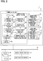
FIG. 2 is a view showing a configuration of an in-vehicle system; -
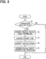
FIG. 3 is a flowchart depicting vehicle packet transmission processing performed by a communication control portion ofFIG. 2 ; -
FIG. 4 is a flowchart depicting vehicle packet reception processing performed by the communication control portion ofFIG. 2 ; -
FIG. 5 is a flowchart depicting processing performed by a vehicle control portion ofFIG. 2 ; -
FIG. 6 is a view showing an example of a changed attention-calling level determined at S28 ofFIG. 5 ; -
FIG. 7 is a view showing an example of a relationship among the attention-calling level ofFIG. 6 , an attention-calling message, and an output style; and -
FIG. 8 is a flowchart depicting vehicle packet reception processing performed in a second modification. - Hereinafter, an embodiment of the present disclosure will be described with reference to the drawings. A
vehicle control system 100 shown inFIG. 1 includes multiple in-vehicle systems 1 and acenter 5. - The multiple in-
vehicle systems 1 are mounted tomultiple vehicles 2, respectively. In an example ofFIG. 1 , an in-vehicle system 1a is mounted to afirst vehicle 2a and an in-vehicle system 1b is mounted to asecond vehicle 2b. The in-vehicle system 1a mounted to thefirst vehicle 2a corresponds to a first vehicle control device and also to a vehicle control device. The in-vehicle system 1b mounted to thesecond vehicle 2b corresponds to a second vehicle control device and also to the vehicle control device. - The in-vehicle systems 1a and 1b are of a same configuration except that each is mounted to a different vehicle. When the in-vehicle systems 1a and 1b are not distinguished from each other, each will be referred to simply as the in-
vehicle system 1. Likewise, when thefirst vehicle 2a and thesecond vehicle 2b are not distinguished from each other, each will be referred to simply as thevehicle 2. InFIG. 1 , only twovehicles 2 each incorporating the in-vehicle system 1 are shown. It should be appreciated, however, that the in-vehicle system 1 may be mounted to three ormore vehicles 2. - The in-
vehicle systems 1 mounted to therespective vehicles 2 wirelessly communicate with each other. Thevehicle 2 is not particularly limited and may be any road vehicle, which includes a four-wheel vehicle, a motorcycle, a bicycle, and so on. - The in-
vehicle system 1 does not use a widearea communication network 3 and uses a radio wave in a pre-assigned frequency band when making wireless communication with another in-vehicle system 1. It should be noted, however, that the in-vehicle system 1 is also capable of wirelessly communicating with another in-vehicle system 1 via the widearea communication network 3. That is, the in-vehicle system 1 is capable of making vehicle-to-vehicle communication either via the widearea communication network 3 or directly without using the widearea communication network 3. - Hereinafter, vehicle-to-vehicle communication without using the wide
area communication network 3 will be referred to as direct vehicle-to-vehicle communication, and vehicle-to-vehicle communication via the widearea communication network 3 will be referred to as indirect vehicle-to-vehicle communication. A communication range is narrower in direct vehicle-to-vehicle communication than in indirect vehicle-to-vehicle communication. Hence, direct vehicle-to-vehicle communication may be referred to also as narrow area vehicle-to-vehicle communication and indirect vehicle-to-vehicle communication as wide area vehicle-to-vehicle communication. - A frequency band used in direct vehicle-to-vehicle communication is, for example, a 760 MHz band. Alternatively, a 2.4 GHz band or a 5.9 GHz band is also available. Any communication standards may be adopted to realize direct vehicle-to-vehicle communication. For example, WAVE (Wireless Access in Vehicular Environment) standards specified in IEEE 1609 standards or the like may be adopted.
- In a case where the in-
vehicle system 1 makes indirect vehicle-to-vehicle communication, the in-vehicle system 1 makes communication directly with abase station 4 connected to the widearea communication network 3. The widearea communication network 3 means a public telecommunication network provided by telecommunication companies, such as a mobile telephone network and the Internet. - The in-
vehicle system 1 transmits a vehicle packet by either direct vehicle-to-vehicle communication or indirect vehicle-to-vehicle communication or by both. A vehicle packet includes a vehicle ID identifying thevehicle 2 incorporating the in-vehicle system 1 (hereinafter, referred to as a subject vehicle), subject vehicle track information based on which a track the subject vehicle is expected to take (hereinafter, referred to as a subject vehicle estimated track) is determined, and an acquisition time indicating a time when the subject vehicle track information is acquired. In a case where a vehicle packet is transmitted by indirect vehicle-to-vehicle communication, thecenter 5 receives the vehicle packet via thebase station 4 and the widearea communication network 3. - In a case where a vehicle packet transmitted from any
vehicle 2 other than the subject vehicle is received, the in-vehicle system 1 makes a determination whether there is a possibility of a collision between the subject vehicle and the vehicle. When determining that there is the possibility of the collision, the in-vehicle system 1 performs an attention-calling control as a vehicle control. - Upon receipt of a vehicle packet, the
center 5 forwards the received vehicle packet to the in-vehicle system 1 mounted to another vehicle (peripheral vehicle) in a peripheral area to the in-vehicle system 1 as a transmitter of the vehicle packet. The peripheral area is a range within a predetermined vehicle-to-vehicle forward distance from the in-vehicle system 1 as the vehicle packet transmitter. The vehicle-to-vehicle forward distance is a distance of a straight line linking two vehicles and is different from a distance by way of thebase station 4. - A location of the
vehicle 2 that transmitted the vehicle packet is necessary to determine the peripheral area. The location is included in the vehicle packet. In addition, locations of the respective in-vehicle systems 1 are necessary to determine the in-vehicle system 1 as a receiver of the forwarded vehicle packet. To satisfy such necessities, thecenter 5 manages present locations of thevehicles 2. - Present locations of the
vehicles 2 may be managed by using an unillustrated database. Present locations of therespective vehicles 2 are correlated with the vehicle IDs and the like and stored in the database. Hereinafter, a database indicating present locations of thevehicles 2 will be referred to as a location management database. The in-vehicle systems 1 may be configured to transmit the present locations to thecenter 5 at regular intervals to let thecenter 5 know the locations of thevehicles 2. It should be noted, however, that the in-vehicle systems 1 may be configured to exchange location information by direct vehicle-to-vehicle communication. In such a case, locations ofmultiple vehicles 2 may be transmitted to thecenter 5 not by all but by some of the in-vehicle systems 1. Meanwhile, thecenter 5 updates the location management database each time locations of thevehicles 2 are received. Locations saved in the location management database may be used instead of locations of thevehicles 2 included in the vehicle packets as a location of thevehicle 2 based on which the peripheral area is determined. - The vehicle-to-vehicle forward distance may be set to a constant value or determined dynamically based on a traveling speed or the like of the vehicle that transmitted the vehicle packet. Alternatively, the vehicle-to-vehicle forward distance may be adjusted dynamically based on a value set for a type of a road the vehicle that transmitted the vehicle packet is traveling. For example, when the vehicle is travelling an expressway, the vehicle-to-vehicle forward distance is set to a relatively large value (for example, 400 m). Meanwhile, when the vehicle is traveling a general road, the vehicle-to-vehicle forward distance is set to a value smaller than the value set for an expressway.
- It is preferable that the vehicle-to-vehicle forward distance is longer than a communication enabled distance by direct vehicle-to-vehicle communication and shorter than a distance several times the communication enabled distance by direct vehicle-to-vehicle communication. Owing to the configuration as above, when indirect vehicle-to-vehicle communication is made, not only can a vehicle-to-vehicle communication distance be substantially increased, but also transmission of a vehicle packet to an unrelated communication party can be prevented. Several times means, for example, two or three times.
- Upon receipt of a vehicle packet, the
center 5 extracts anyvehicle 2 present within the vehicle-to-vehicle forward distance from the vehicle that transmitted the vehicle packet by referring to the location management database and forwards the received vehicle packet to every extractedvehicle 2. - A configuration of the in-
vehicle system 1 will now be described. As is shown inFIG. 2 , the in-vehicle system 1 includes acommunication unit 10, alocator 60, avehicle control portion 70, and anotification portion 80. Thecommunication unit 10 is connected to thelocator 60 and thevehicle control portion 70 via a LAN (Local Area Network) 50, which is a communication network constructed in a vehicle, and communicates with each. In short, thecommunication unit 10, thelocator 60, and thevehicle control portion 70 are provided as separate bodies in the present embodiment. - The
locator 60 is a device which indicates a spot the subject vehicle is presently traveling on a road map. Thelocator 60 includes aGNSS receiver 61 and amap storage portion 62. TheGNSS receiver 61 receives a navigation signal transmitted from a navigation satellite provided to a GNSS (Global Navigation Satellite System) as a satellite navigation system and calculates a present location one after another based on the received navigation signal. Owing to theGNSS receiver 61, thelocator 60 is capable of outputting a UTC time, that is, a present time in Coordinated Universal Time representation in a same manner as a typical GNSS receiver. The UTC time outputted from thelocator 60 is used to correct a time measured by aclock portion 402 included in thecommunication unit 10. - The
map storage portion 62 preliminary stores road map data indicating connection relationships of roads and shapes of roads (in other words, road structures). Themap storage portion 62 is realized by using a non-volatile storage medium, such as a hard disk drive. - The
locator 60 identifies a location of the subject vehicle on the road map based on the present location detected by theGNSS receiver 61. A location of a vehicle on the road map may be identified with the aid of an existing map matching technique commonly used in a navigation device. The map matching technique is a technique to find a present location of a vehicle by finding a traveled track of the vehicle from locations of the vehicle at multiple times and by comparing the traveled track of the vehicle with a road shape acquired from map information. Thelocator 60 successively provides location information indicating a present location to thecommunication unit 10. Thelocator 60 only has to be furnished with the function described above. In a case where a navigation device is mounted to the subject vehicle, the navigation device may be used as thelocator 60. - The
vehicle control portion 70 is a computer including a CPU, a RAM, a ROM, an input-output, and a bus line interconnecting the foregoing components, and the like. A program causing the computer to function as thevehicle control portion 70 is stored in the ROM. The program only has to be stored in a non-transitory tangible storage medium and may be stored in a storage medium other than the ROM. Running the program stored in the ROM on the CPU corresponds to performing a method in accordance with the program. A control performed by thevehicle control portion 70 will be described below by usingFIG. 5 . - The
notification portion 80 includes a display and a speaker and outputs an attention-calling message from the display and the speaker under control of thevehicle control portion 70. - The
communication unit 10 is a unit enabling transmission and reception of a vehicle packet between the subject vehicle and the in-vehicle system 1 mounted to a vehicle present near the subject vehicle (hereinafter, referred to as a peripheral vehicle). Thecommunication unit 10 includes a narrowarea communication portion 20, a widearea communication portion 30, and acommunication control portion 40. Each of the narrowarea communication portion 20 and the widearea communication portion 30 is connected to thecommunication control portion 40 to make communication with each other. - The narrow
area communication portion 20 is a communication module making direct wireless communication (that is, direct vehicle-to-vehicle communication) with another vehicle by using a radio wave in a predetermined frequency band. The narrowarea communication portion 20 includes a narrowarea transmission portion 21, a narrowarea reception portion 22, and anantenna 23. Theantenna 23 is an antenna at which a radio wave in a frequency band used in direct vehicle-to-vehicle communication is transmitted and received. - The narrow
area reception portion 22 demodulates a signal received at theantenna 23 and provides the demodulated signal to thecommunication control portion 40. The narrowarea transmission portion 21 modulates data inputted from thecommunication control portion 40 and outputs the modulated data to theantenna 23. Theantenna 23 radiates the received data as a radio wave (that is, by wireless transmission). An access control in direct vehicle-to-vehicle communication is performed by using CSMA with CA (Carrier Sense Multiple Access with Collision Avoidance). Access control processing by using the CSMA with CA may be performed by either the narrowarea transmission portion 21 or thecommunication control portion 40. A transmission method adopted in the present embodiment is a broadcast method. However, a unicast or multicast method may be adopted instead. - The wide
area communication portion 30 is a communication module wirelessly connecting to the widearea communication network 3 to enable the in-vehicle system 1 to communicate with another communication device via the widearea communication network 3. The widearea communication portion 30 includes a widearea transmission portion 31, a widearea reception portion 32, and anantenna 33. - The
antenna 33 is an antenna at which a radio wave in a predetermined frequency band used in wireless communication with thebase station 4 is transmitted and received. The widearea reception portion 32 demodulates a signal transmitted from thebase station 4 and received at theantenna 33 and provides the demodulated signal to thecommunication control portion 40. The widearea transmission portion 31 modulates data inputted from thecommunication control portion 40 and outputs the modulated data to theantenna 33. Theantenna 33 radiates the input data as a radio wave (that is, by wireless transmission). - The
communication control portion 40 has a function of generating a vehicle packet and transmitting the vehicle packet from at least one of the narrowarea transmission portion 21 and the widearea transmission portion 31. Thecommunication control portion 40 also has a function of outputting data generated based on a vehicle packet received by at least one of the narrowarea reception portion 22 and the widearea reception portion 32 to thevehicle control portion 70. - To execute the functions described above, the
communication control portion 40 includes, as is shown inFIG. 2 , a subject vehicle trackinformation acquisition portion 401, aclock portion 402, atime acquisition portion 403, a vehiclepacket generation portion 404, atransmission control portion 405, areception determination portion 406, anidentity determination portion 407, amemory 408, adelay calculation portion 409, and an in-vehicle transmission portion 410. - The
communication control portion 40 is formed as a computer including a CPU, a RAM, a ROM, an input-output, a bus line interconnecting the foregoing components, and the like. A program causing the computer to function as the communication control portion 40 (hereinafter, referred to as a communication control program), the vehicle ID, and so on are stored in the ROM. The communication control program only has to be stored in a non-transitory tangible storage medium and may be stored in a storage medium other than the ROM. For example, the communication control program may be saved in a flash memory. Running the communication control program on the CPU corresponds to performing a method in accordance with the communication control program. By running the communication control program stored in the ROM on the CPU, various functions shown inFIG. 2 are provided by thecommunication control portion 40. - Functional blocks included in the
communication control portion 40, either in part or in whole, may be realized by using one or more than one IC or the like (in other words, by hardware). Alternatively, the functional blocks included in thecommunication control portion 40, either in part or in whole, may be realized by combining software run on the CPU and hardware members. - The subject vehicle track
information acquisition portion 401 acquires subject vehicle track information. The subject vehicle track information is information based on which a track the subject vehicle is expected to take, that is, a subject vehicle estimated track is determined. To be more specific, the subject vehicle track information includes a present location, a speed, and a traveling direction of the subject vehicle in the present embodiment. A present location of the subject vehicle is acquired from thelocator 60 and a speed is acquired from an unillustrated vehicle speed sensor. A traveling direction is determined based on a change in present location of the subject vehicle. - In the present embodiment, the subject vehicle track information is acquired at an instant when a distance from a location of the subject vehicle to a crossing point becomes equal to a first attention-calling distance. The crossing point is an intersection or a merging point. The first attention-calling distance is preliminarily set based on a distance within which any
other vehicle 2 headed for the crossing point is recommended to take a caution against the subject vehicle. For example, the first attention-calling distance is within a range from 50 m to 100 m. Whether a distance from a location of the subject vehicle to the crossing point becomes equal to the first attention-calling distance is determined based on information from thelocator 60. Such a determination is made at regular intervals while thecommunication control portion 40 is energized. Thecommunication control portion 40 is energized, for example, while an ignition switch stays ON. - The subject vehicle track
information acquisition portion 401 notifies thetime acquisition portion 403 that processing to acquire the subject vehicle track information has been performed. Such a notification may be made at an instant when the subject vehicle track information is actually acquired or at an instant when an acquisition request for the subject vehicle track information is outputted to theLAN 50. The subject vehicle trackinformation acquisition portion 401 outputs the acquired subject vehicle track information to the vehiclepacket generation portion 404. - The
clock portion 402 successively measures a present time. Theclock portion 402 is also furnished with a function of correcting a present time to a UTC time when the UTC time is supplied from thelocator 60. - Upon receipt of a notice from the subject vehicle track
information acquisition portion 401 informing that the processing to acquire the subject vehicle track information has been performed, thetime acquisition portion 403 acquires a present time from theclock portion 402 and outputs the acquired present time (hereinafter, referred to as an acquired time) to the vehiclepacket generation portion 404. Thetime acquisition portion 403 also acquires a present time from theclock portion 402 at a request from thedelay calculation portion 409 and outputs the acquired time to thedelay calculation portion 409. - Once the subject vehicle track information and the acquired time are successfully received, the vehicle
packet generation portion 404 generates a vehicle packet including the subject vehicle track information, the acquired time, and the vehicle ID. A header identifying as being a vehicle packet is appended to the vehicle packet. The vehicle packet thus generated is outputted to thetransmission control portion 405. In the present embodiment, a packet means entire data including the subject vehicle track information, the acquired time, and the vehicle ID, and does not mean a unit of data divided to a certain amount at a time of transmission. A definition of a vehicle packet as above does not necessarily mean that a vehicle packet is divided into multiple items of data when transmitted. - Upon input of a vehicle packet, the
transmission control portion 405 transmits the vehicle packet from one or both of the narrowarea transmission portion 21 and the widearea transmission portion 31. In a case where the vehicle packet is transmitted from both of the narrowarea transmission portion 21 and the widearea transmission portion 31, thetransmission control portion 405 outputs the vehicle packet to each of the narrowarea transmission portion 21 and the widearea transmission portion 31. - When the vehicle packet is outputted to each of the narrow
area transmission portion 21 and the widearea transmission portion 31, the vehicle packet is wirelessly transmitted from the narrowarea transmission portion 21 via theantenna 23 while the vehicle packet is also transmitted from the widearea transmission portion 31 via theantenna 33. It should be noted, however, that a vehicle packet is not necessarily transmitted from the narrowarea transmission portion 21 and the widearea transmission portion 31 as soon as the vehicle packet is inputted into thetransmission control portion 405. - As has been described above, a vehicle packet is transmitted from the narrow
area transmission portion 21 after the vehicle packet is processed by using the CSMA with CA as an access control method. Also, a vehicle packet is transmitted from the widearea transmission portion 31 after the vehicle packet is processed in accordance with predetermined communication standards for the widearea communication network 3. An example of the communication standards for the widearea communication network 3 is an LTE (Long Term Evolution). In accordance with the LTE, thecommunication unit 10 communicates with thebase station 4 and performs internal processing for allocation of a resource block. Thecommunication unit 10 transmits a vehicle packet by using a resource block allocated as a result. - The processing as above is necessary. In addition, processing to transmit a vehicle packet from the narrow
area transmission portion 21 and the widearea transmission portion 31 is performed simultaneously and in parallel with another processing by sharing time or the like in some case. Accordingly, waiting may possibly occur until processing to transmit a vehicle packet is performed. Hence, the vehicle packet is not necessarily transmitted from the narrowarea transmission portion 21 and the widearea transmission portion 31 as soon as the vehicle packet is inputted into thetransmission control portion 405. In addition, even when thetransmission control portion 405 starts to control the narrowarea transmission portion 21 and the widearea transmission portion 31 at a same time to transmit vehicle packets, the vehicle packets are not necessarily transmitted from the narrowarea transmission portion 21 and the widearea transmission portion 31 at a same time. - The process of controlling the narrow
area transmission portion 21 to transmit the vehicle packet and the process of controlling the widearea transmission portion 31 to transmit the vehicle packet may be performed by thetransmission control portion 405 or may be performed by the narrowarea transmission portion 21 and the widearea transmission portion 31. - Upon supply of a vehicle packet, the narrow
area transmission portion 21 modulates the vehicle packet and broadcasts the modulated vehicle packet from theantenna 23. Upon supply of a vehicle packet, the widearea transmission portion 31 also modulates the vehicle packet and transmits the modulated vehicle packet from theantenna 33. The vehicle packet transmitted from theantenna 33 is received by thebase station 4 and forwarded to thecenter 5 from thebase station 4 via the widearea communication network 3. At thebase station 4, a time is also required for processing to transmit the vehicle packet to thecenter 5. Processing in thebase station 4 is more likely to delay when a volume of data transmitted from terminals, such as thecommunication unit 10, and processed at a same time in thebase station 4 increases. - In a case where a vehicle packet is transmitted from the narrow
area transmission portion 21 in the in-vehicle system 1 mounted to anothervehicle 2 and the subject vehicle is allowed to communicate with thevehicle 2 by narrow area communication, the vehicle packet transmitted from thevehicle 2 is received by the narrowarea reception portion 22 via theantenna 23. - In a case where the subject vehicle is in the peripheral area determined by the
center 5 in reference to a location of anothervehicle 2, a vehicle packet transmitted from thevehicle 2 in question is transmitted from thecenter 5. The vehicle packet transmitted from thecenter 5 is received by the widearea reception portion 32 via theantenna 33. - The
reception determination portion 406 successively acquires data received by the narrowarea reception portion 22 and the widearea reception portion 32 and determines whether data received by the narrowarea reception portion 22 and the widearea reception portion 32 is a vehicle packet transmitted from anothervehicle 2 each time the data is acquired. Such a determination is made by analyzing, for example, the header. In a case where reception of a vehicle packet is determined, thereception determination portion 406 outputs the vehicle packet to theidentity determination portion 407. - In a case where reception of a vehicle packet is determined by the
reception determination portion 406, theidentity determination portion 407 determines whether the received vehicle packet is same as a vehicle packet stored in thememory 408. Such a determination is made by, for example, checking a match of both of the vehicle ID and the acquired time between the vehicle packets. - Both of the vehicle ID and the acquired time match between the vehicle packets only when a same vehicle packet is transmitted from the narrow
area transmission portion 21 and the widearea transmission portion 31 of anothervehicle 2 and received by both of the narrowarea reception portion 22 and the widearea reception portion 32 of the subject vehicle. Hence, a determination by theidentity determination portion 407 is to determine whether the vehicle packet received by the widearea reception portion 32 is same as the vehicle packet received by the narrowarea reception portion 22. - In a case where identity between the received vehicle packet and the vehicle packet stored in the
memory 408 is not determined (the former and the latter are not same), theidentity determination portion 407 transmits the vehicle track information and the vehicle ID included in the received vehicle packet to the in-vehicle transmission portion 410 and saves the vehicle track information and the vehicle ID in thememory 408 for a predetermined time. Theidentity determination portion 407 also outputs the acquired time included in the received vehicle packet to thedelay calculation portion 409. - Meanwhile, in a case where identity between the received vehicle packet and the vehicle packet stored in the
memory 408 is determined, theidentity determination portion 407 discards the received vehicle packet. - Upon input of the acquired time from the
identity determination portion 407, thedelay calculation portion 409 makes thetime acquisition portion 403 acquire a present time and acquires the present time from thetime acquisition portion 403. The present time thus acquired will be referred to as a reception time. A difference between the reception time and the acquired time is calculated, which will be hereinafter referred to as a communication delay time ΔT. The communication delay time ΔT thus calculated is outputted to the in-vehicle transmission portion 410. - Upon supply of the vehicle track information and the vehicle ID from the
identity determination portion 407, the in-vehicle transmission portion 410 outputs the vehicle track information and the vehicle ID thus supplied and the communication delay time ΔT supplied from thedelay calculation portion 409 to thevehicle control portion 70. The in-vehicle transmission portion 410 functioning to output the communication delay time ΔT to thevehicle control portion 70 corresponds to a delay time output portion. - Vehicle packet transmission processing performed by the
communication control portion 40 will now be described by using a flowchart ofFIG. 3 . The following will describe a case where processing ofFIG. 3 is performed by thecommunication control portion 40 in the in-vehicle system 1a mounted to thefirst vehicle 2a. Herein, the in-vehicle system 1a functions as the first vehicle control device. The subject vehicle trackinformation acquisition portion 401 corresponds to a first vehicle information acquisition portion and the narrowarea transmission portion 21 and the widearea transmission portion 31 correspond to a first vehicle transmission portion. - The
communication control portion 40 repetitively performs the processing depicted in the flowchart ofFIG. 3 at regular intervals, for example, 100 milliseconds. In the following, S stands for step. S1 and S2 are performed by the subject vehicle trackinformation acquisition portion 401. At S1, whether thefirst vehicle 2a is approaching a crossing point is determined. To be more specific, a determination is made as to whether a distance from thefirst vehicle 2a to the crossing point changes from a distance longer than the first attention-calling distance to a distance equal to or less than the first attention-calling distance. Such a determination is made by using a location of thefirst vehicle 2a identified by thelocator 60 and the road map data stored in themap storage portion 62 in thelocator 60. As has been described above, the crossing point is an intersection or a merging point. - In a case where the determination made at S1 is NO, the processing of
FIG. 3 is ended. Meanwhile, in a case where the determination made at S1 is YES, advancement is made to S2. At S2, the subject vehicle track information is acquired. The subject vehicle track information acquired by the in-vehicle system 1a mounted to thefirst vehicle 2a corresponds to first vehicle track information and also to first vehicle information. - As has been described above, the subject vehicle track information includes a present location, a speed, and a traveling direction of the subject vehicle, herein the
first vehicle 2a. The present location may be the present location used for the determination at S1 or acquired from thelocator 60 at S2. - Processing at S3 is performed by the
time acquisition portion 403 to acquire a present time. Processing at S4 is performed by the vehiclepacket generation portion 404 to generate a vehicle packet including the present time acquired at S3 as the acquired time, the subject vehicle track information acquired at S2, and the vehicle ID. - Hereinafter, a vehicle packet generated by the in-vehicle system 1a mounted to the
first vehicle 2a will be referred to as a first vehicle packet, the acquired time included in the first vehicle packet as a first time, and the subject vehicle track information included in the first vehicle packet as first vehicle track information. - Processing at S5 is performed by the
transmission control portion 405 to transmit the first vehicle packet generated at S4 from one or both of the narrowarea transmission portion 21 and the widearea transmission portion 31. The processing has been described in detail above and the description is not repeated. - Vehicle packet reception processing performed by the
communication control portion 40 will now be described by using a flowchart ofFIG. 4 . The following will describe a case where thecommunication control portion 40 in the in-vehicle system 1b mounted to thesecond vehicle 2b performs the processing ofFIG. 4 . Herein, the in-vehicle system 1b functions as the second vehicle control device. The narrowarea reception portion 22 and the widearea reception portion 32 correspond to a second vehicle reception portion. Also, thesecond vehicle 2b is in a periphery of thefirst vehicle 2a, that is, thesecond vehicle 2b is a peripheral vehicle present near thefirst vehicle 2a, which means that anyvehicle 2 present near thesecond vehicle 2b is deemed as being thefirst vehicle 2a. - The
communication control portion 40 also repetitively performs processing depicted in the flowchart ofFIG. 4 at regular intervals, for example, 100 milliseconds. Processing at S11 is performed by thereception determination portion 406 to determine whether a vehicle packet is received. Such a determination is made by analyzing signals acquired from the narrowarea reception portion 22 and the widearea reception portion 32. In a case where the determination made at S11 is NO, the processing ofFIG. 4 is ended. Meanwhile, in a case where the determination made at S11 is YES, advancement is made to S12. - Processing at S12 through S14 is performed by the
identity determination portion 407. At S12, a determination is made as to identity between the vehicle packet, reception of which is determined at S11, and the vehicle packet already received and stored in thememory 408. In a case where the determination made at S12 is YES, advancement is made to S13. - At S13, the most recently received vehicle packet is discarded. In a case where the determination made at S12 is YES, advancement is made to S14. At S14, the most recently received vehicle packet is stored in the
memory 408. Although it is not depicted inFIG. 4 , the vehicle packet stored in thememory 408 is erased from thememory 408 when a predetermined time elapses. - Processing at S15 is performed by the
time acquisition portion 403 to acquire a present time. In a case where the first vehicle packet is received, the present time means a time when reception of the first vehicle packet is determined and will be referred to as a second time. Herein, thetime acquisition portion 403 functions as a second time acquisition portion. Because thefirst vehicle 2a is a peripheral vehicle present near thesecond vehicle 2b, the first vehicle packet corresponds to a vehicle packet transmitted from a peripheral vehicle present near thesecond vehicle 2b, that is, a peripheral vehicle packet. The first vehicle track information included in the first vehicle packet corresponds to peripheral vehicle information. - Processing at S16 is performed by the
delay calculation portion 409 to calculate the communication delay time ΔT by subtracting the first time included in the first vehicle packet from the present time (second time) acquired at S15. - Processing at S17 is performed by the in-
vehicle transmission portion 410 to output the first vehicle track information and the vehicle ID included in the most recently received vehicle packet and the communication delay time ΔT calculated at S16 to thevehicle control portion 70. - Processing performed by the
vehicle control portion 70 will now be described by using a flowchart ofFIG. 5 . The following will describe a case where thevehicle control portion 70 in the in-vehicle system 1b mounted to thesecond vehicle 2b performs processing ofFIG. 5 . Herein, thevehicle control portion 70 corresponds to a second vehicle control portion. Thevehicle control portion 70 repetitively performs the processing depicted in the flowchart ofFIG. 5 at regular intervals, for example, 100 milliseconds or several dozen milliseconds. - At S21, a determination is made as to whether the first vehicle track information, the vehicle ID, and the communication delay time AT are inputted. In a case where the determination is NO, the processing of
FIG. 5 is ended. Meanwhile, in a case where the determination made at S21 is YES, advancement is made to S22. - At S22 through S26, whether there is a possibility of a collision between the
second vehicle 2b and thefirst vehicle 2a is determined. At S22, the vehicle track information of the subject vehicle (herein, thesecond vehicle 2b) is acquired. The vehicle track information acquired herein includes a present location, a speed, and a traveling direction of thesecond vehicle 2b. - At S23, a first vehicle estimated track, which is a feature track of the
first vehicle 2a, and a second vehicle estimated track, which is a feature track of thesecond vehicle 2b, are determined. The first vehicle estimated track is determined by using the first vehicle track information and the second vehicle estimated track is estimated by using the vehicle track information acquired at S22. - At S24, whether there is a crossing point (hereinafter, referred to as a track crossing point) on the first vehicle estimated track and the second vehicle estimated track determined at S23 is determined. In a case where the determination made at S24 is NO, the processing of
FIG. 5 is ended. Meanwhile, in a case where the determination made at S24 is YES, advancement is made to S25. - At S25, whether the track crossing point is on an interchange is determined. In a case where the determination is YES, the processing of
FIG. 5 is ended, because thefirst vehicle 2a and thesecond vehicle 2b do not collide as long as the track crossing point is on the intersection. In a case where the determination made at S25 is NO, advancement is made to S26. - At S26, whether the subject vehicle (the
second vehicle 2b) is also approaching the crossing point is determined. To be more specific, whether thesecond vehicle 2b is headed for the crossing point and a distance from thesecond vehicle 2b to the crossing point becomes equal to or less than a second attention-calling distance is determined. The second attention-calling distance is preliminarily set. The second attention-calling distance may be as long as the first attention-calling distance or longer or shorter than the first attention-calling distance. In a case where the determination made at S26 is NO, the processing ofFIG. 5 is ended. Meanwhile, in a case where the determination made at S26 is YES, advancement is made to S27. When advancement is made to S27, it has been determined that there is the possibility of the collision between thesecond vehicle 2b and thefirst vehicle 2a. - At S27, a traveled distance the
first vehicle 2a has traveled for the communication delay time ΔT is calculated by using the communication delay time ΔT, an input of which is determined at S21, and a vehicle speed of thefirst vehicle 2a included in the first vehicle track information, an input of which is also determined at S21. - At S28, an attention-calling level set at a default level is maintained or changed based on the traveled distance calculated at S27. To be more specific, the attention-calling level is changed by increasing the attention-calling level set at the default level with an increase in the traveled distance. The attention-calling level set at the default level is a level set on an assumption that the communication delay time ΔT is 0. That is, the attention-calling level set at the default level is a level set on a condition that a distance from a location of the
second vehicle 2b to the crossing point is equal to the second attention-calling distance. In short, an attention-calling control performed when the attention-calling level is at the default level corresponds to a delay ignoring control. - By contrast, a distance from the
second vehicle 2b to the crossing point becomes shorter than the second attention-calling distance at least by the traveled distance calculated at S27 by the time processing at S28 is performed. Hence, the attention-calling level is increased at S28 based on the traveled distance calculated at S27. - In
FIG. 6 , an example of the changed attention-calling level determined at S28 is shown. In the example ofFIG. 6 , the attention-calling level is increased step by step based on the traveled distance. - At S29, an attention-calling control corresponding to the attention-calling level changed at S28 is performed. The attention-calling control performed in the present embodiment is a control to output an attention-calling message from the display and the speaker provided to the
notification portion 80. A control content changed with the attention-calling level is a content of an attention-calling message and an output style of the attention-calling message. - In
FIG. 7 , a relationship among the attention-calling level, the attention-calling message, and the output style is shown. An attention-calling message having a default content is a low-level message, which reads, for example, "Be aware of another vehicle". A medium-level message has a content attracting attention of a driver to anothervehicle 2 more firmly than the low-level message. A high-level message is a message directing the driver to immediately take an action to avoid a collision with anothervehicle 2. - In the present embodiment, an output style of the attention-calling message is not only to display the attention-calling message on the display provided to the
notification portion 80 but also to flash a predetermined flashing region of the display. Herein, "to flash" means to blink the flashing region for a predetermined time. The flashing region may be a periphery along a region where the attention-calling message is being displayed, an entire surface of the display, or the region where the attention-calling message is being displayed. - The flashing region is not flashed in a default setting. A flashing interval is set to "long" and flashing brightness is set to "low" when the attention-calling level is increased by one step from the default level. The flashing interval is set to "medium" and the flashing brightness is also set to "medium" when the attention-calling level is increased by two steps from the default level. The flashing interval is set to "short" and the flashing brightness is set to "high" when the attention-calling level is increased by three steps from the default level. Specific "long", "medium", and "short" flashing intervals are set preliminarily and specific "low", "medium", and "high" flashing brightness are also set preliminarily. The driver more readily becomes aware of an output of the attention-calling message as the flashing interval becomes shorter. Also, the driver more readily becomes aware of an output of the attention-calling message as the flashing brightness is increased.
- The attention-calling control performed when the attention-calling level is at the default level corresponds to the delay ignoring control whereas the attention-calling control performed when the attention-calling level is higher than the default level corresponds to a delay considering control. A state in which the
vehicle control portion 70 is allowed to perform the attention-calling control corresponding to the communication delay considering control can be said as a delay considering mode. - At S29, the attention-calling control is performed by outputting an attention-calling message in an output style determined by the relationship set forth in
FIG. 7 and at the attention-calling level determined at S28. The attention-calling message may be displayed continuously for a predetermined time. Alternatively, it may be configured to display the attention-calling message and flash the flashing region alternately and to end both a display of the attention-calling message and flashing of the flashing region when a control performance time elapses. In a case where the attention-calling message is displayed continuously for a predetermined time, the flashing region may be flashed first, or the flashing region may be flashed at a same time when the attention-calling message is displayed. - In the first embodiment described above, the attention-calling control is performed by maintaining the attention-calling level at the default level or raising the attention-calling level from the default level based on the communication delay time ΔT calculated as a difference between the first time when the in-vehicle system 1a mounted to the
first vehicle 2a has acquired the first vehicle track information and the second time when reception of the first vehicle packet including the first vehicle track information is determined by the in-vehicle system 1b mounted to thesecond vehicle 2b. - Given that the first attention-calling distance is 100 m. Then, an attention-calling message corresponding to the attention-calling level at the default level is an attention-calling message against the
first vehicle 2a assumed to be traveling 100 m before the crossing point. Given that the travelled distance calculated at S27 is 50 m. Also, given that thefirst vehicle 2a is travelling 100 m before the crossing point at a time T1 shown inFIG. 1 and thefirst vehicle 2a is travelling 50 m before the crossing point at a time T2. - Then, an attention-calling message outputted in the
second vehicle 2b is an attention-calling message against thefirst vehicle 2a assumed to be traveling 100 m before the crossing point when thefirst vehicle 2a is actually traveling 50 m before the crossing point unless the communication delay time ΔT is considered. Hence, attention is called insufficiently. - By contrast, the attention-calling level is changed in consideration of the communication delay time ΔT and the attention-calling control is performed at the changed attention-calling level in the present embodiment. Accordingly, a control can be restricted from becoming insufficient even when there is the communication delay time ΔT. Consequently, the driver of the
second vehicle 2b can be restricted from having a feeling of strangeness the driver may have otherwise by insufficiently called attention. - In the present embodiment, a traveled distance the
first vehicle 2a has traveled for the communication delay time ΔT is calculated by multiplying the communication delay time ΔT by a vehicle speed of thefirst vehicle 2a, and the attention-calling level is determined based on the traveled distance. The communication delay time ΔT itself is a value calculated in consideration of a location of thefirst vehicle 2a when the attention-calling control is performed. However, by determining the attention-calling level based on the traveled distance, the attention-calling level can be determined more appropriately to a location of thefirst vehicle 2a when the attention-calling control is performed. - In the present embodiment, not only the attention-calling message but also an output style of the attention calling message is changed based on the attention-calling level. Hence, in a circumstance where it is crucial for the driver of the
second vehicle 2b to become aware of the attention-calling message quickly, the driver of thesecond vehicle 2b more readily becomes aware of the attention-calling message. - In the present embodiment, even when there is a track crossing point, it is not determined that there is a possibility of a collision if the track crossing point is on an interchange. Hence, the attention-calling control can be restricted from being performed unnecessarily.
- While the above has described the embodiment of the present disclosure, it should be appreciated that the present disclosure is not limited to the embodiment described above and various modifications described below are within the technical scope of the present disclosure. Besides the modifications described below, the present disclosure can be modified in various manners within the scope of the present disclosure.
- In the embodiment above, the in-vehicle system 1a mounted to the
first vehicle 2a transmits the first vehicle packet only once when an approach of thefirst vehicle 2a to the crossing point is determined. In response, thesecond vehicle 2b performs the attention-calling control based on the first vehicle packet transmitted only once. - However, it may be configured to repeat S2 through S5 of
FIG. 3 after an approach of thefirst vehicle 2a to the crossing point is determined. When configured as above, latest subject vehicle track information (that is, first vehicle track information) is successively determined and the first vehicle packet including the latest first vehicle track information is transmitted one after another. Transmission of the first vehicle packet is ended when a first vehicle packet transmission time has elapsed after the transmission is started or when thefirst vehicle 2a has traveled a first vehicle packet transmission distance after the transmission is started. - In a case where the in-vehicle system 1a mounted to the
first vehicle 2a transmits the first vehicle packet one after another, the in-vehicle system 1b mounted to thesecond vehicle 2b sets an end condition to end the attention-calling control even when the first vehicle packet is being received one after another. The end condition is, for example, a detection of a recognition operation indicating that the driver of thesecond vehicle 2b has recognized thefirst vehicle 2a. The recognition operation is, for example, pressing of a button assigned for recognition of thefirst vehicle 2a. Alternatively, the recognition operation may be a braking operation. - Because the in-vehicle system 1a mounted to the
first vehicle 2a transmits the first vehicle packet one after another, thereception determination portion 406 in the in-vehicle system 1b mounted to thesecond vehicle 2b is supposed to repetitively determine reception of the first vehicle packet. Hence, in a case where thereception determination portion 406 fails to determine reception of the first vehicle packet over a period longer than a reference time, a non-reception notice informing such a failure is transmitted to thevehicle control portion 70. The reference time is set to a time shorter than the first vehicle packet transmission time and also shorter than a time required for thefirst vehicle 2a to travel the first vehicle packet transmission distance. - In a case where the non-reception notice is received, the
vehicle control portion 70 determines that a failure in reception of the first vehicle packet is not attributed to a malfunction of thecommunication unit 10 including the narrowarea reception portion 22 and the widearea reception portion 32 because thecommunication unit 10 which has successfully transmitted the non-reception notice is functioning normally. - The
vehicle control portion 70 ends the delay considering mode upon receipt of the non-reception notice and performs a preliminarily set control without received packet. The control without received packet is a control which can be performed even without the first vehicle packet. For example, the control without received packet is a control to make thenotification portion 80 output a message informing an incapability of identifying a location of thefirst vehicle 2a. - In a case where such a message is outputted from the
notification portion 80, the driver of thesecond vehicle 2b can know that the driver has to stay cautious about thefirst vehicle 2a even when the attention-calling message is no longer outputted. - In the embodiment above, a present time used as the second time is acquired after reception of a vehicle packet is determined. By contrast, as is depicted in
FIG. 8 , a present time is acquired by performing S15 before S11 in a second modification. Accordingly, a present time is acquired at regular intervals in the vehicle packet reception processing in the second modification. When reception of a new vehicle packet is determined, S16A is performed, in which a latest present time among times acquired as a present time by repetitively performing S15 is selected as the second time. The communication delay time ΔT is calculated from the second time thus selected and the first time included in the received vehicle packet. - When configured in the manner as above, the second time is acquired before a vehicle packet including the first time is received. Hence, it is no longer necessary to perform processing to acquire the second time after reception of the vehicle packet is determined. Accordingly, the following processing can be started earlier by saving a time required for the processing to acquire the second time.
- In the embodiment above, a vehicle packet is generated and transmitted when an approach of the subject vehicle to the crossing point is determined. However, a vehicle packet may be generated and transmitted at regular intervals without determining whether the subject vehicle is approaching the crossing point. In such a case, an onset of a vehicle packet generation period is determined at S1 of
FIG. 3 instead of determining an approach of the subject vehicle to the crossing point. - In the embodiment above, the
vehicle control portion 70 performs the attention-calling control to call attention of the driver of the subject vehicle. However, a vehicle control performed by thevehicle control portion 70 may be an automatic control of behaviors of the subject vehicle. In such a case, the delay considering control is performed by increasing a control amount of the delay ignoring control by an amount determined based on the communication delay time ΔT. - In the embodiment above, the in-vehicle system 1a mounted to the
first vehicle 2a transmits the first vehicle track information as the first vehicle information when an approach of a location of thefirst vehicle 2a to the crossing point is determined. In response, the in-vehicle system 1b mounted to thesecond vehicle 2b performs the attention-calling control when it is determined that thesecond vehicle 2b is also approaching the crossing point. - However, by allowing the in-vehicle system 1a mounted to the
first vehicle 2a and the in-vehicle system 1b mounted to thesecond vehicle 2b to transmit and receive respective locations at regular intervals, the in-vehicle system 1a mounted to thefirst vehicle 2a becomes capable of determining when the in-vehicle system 1b mounted to thesecond vehicle 2b is to perform the attention-calling control against thefirst vehicle 2a. In such a case, it is not necessary to transmit the first vehicle track information as the first vehicle information and it is sufficient to transmit attention-calling direction information directing to start the attention-calling control against the first vehicle to the in-vehicle system 1b mounted to thesecond vehicle 2b. - In the embodiment above, the
communication unit 10 includes two communication portions, namely the narrowarea communication portion 20 and the widearea communication portion 30. However, thecommunication unit 10 may include either one of the narrowarea communication portion 20 and the widearea communication portion 30. - In the embodiment above, the flashing region is flashed to let the driver of the
second vehicle 2b more readily become aware of an output of the attention-calling message with the increase in the attention-calling level. However, an output style that lets the driver more readily become aware of the attention calling message is not limited to flashing of the flashing region. In a case where the attention-calling message is outputted on a display portion, a size of the attention-calling message may be changed instead. - In a case where the attention-calling message is outputted from the speaker as a sound, a volume of the sound may be changed. Alternatively, an alert signal sound may be inserted between attention-calling message sounds.
- In the embodiment above, the attention-calling level is maintained or changed based on a traveled distance of the
first vehicle 2a for the communication delay time ΔT, which is calculated by multiplying the communication delay time ΔT by a vehicle speed. However, the attention-calling level may be maintained or changed based on the communication delay time ΔT alone without consideration of a vehicle speed. - While the disclosure has been described with reference to preferred embodiments thereof, it is to be understood that the disclosure is not limited to the preferred embodiments and constructions. The disclosure is intended to cover various modification and equivalent arrangements. In addition, the various combinations and configurations, which are preferred, other combinations and configurations, including more, less or only a single element, are also within the spirit and scope of the disclosure.
Claims (10)
- A vehicle control system (100) comprising:a first vehicle control device (1a) used in a first vehicle (2a); anda second vehicle control device (1b) used in a second vehicle (2b),
whereinthe first vehicle control device includes,a first vehicle information acquisition portion (401) acquiring first vehicle information based on which the second vehicle control device in the second vehicle starts a vehicle control against the first vehicle,a vehicle packet generation portion (404) acquiring a first time indicating a time when the first vehicle information is acquired and generating a first vehicle packet including the first time and the first vehicle information, anda first vehicle transmission portion (21, 31) transmitting the first vehicle packet, andthe second vehicle control device includes,a second vehicle reception portion (22, 32) receiving the first vehicle packet,a reception determining portion (406) acquiring a signal received by the second vehicle reception portion and successively determining whether the first vehicle packet is received,a second time acquisition portion (403) acquiring a second time indicating a time when the reception determining portion determines that the first vehicle packet is received,a delay calculation portion (409) calculating a communication delay time that is a difference between the first time included in the first vehicle packet received by the second vehicle reception portion and the second time acquired by the second time acquisition portion, anda second vehicle control portion (70) performing a delay considering control that is set by changing a delay ignoring control based on the communication delay time, the delay ignoring control being the vehicle control set based on the first vehicle information when assuming that the first time and the second time are same. - The vehicle control system according to claim 1, whereinthe first vehicle information acquisition portion acquires first vehicle track information as the first vehicle information, the first vehicle track information being information for determining a first vehicle estimated track that is a future track of the first vehicle, andthe second vehicle control portion determines the first vehicle estimated track based on the first vehicle track information included in the first vehicle packet received by the second vehicle reception portion, determines a second vehicle estimated track that is a feature track of the second vehicle, determines whether there is a possibility of a collision between the first vehicle and the second vehicle based on the first vehicle estimated track and the second vehicle estimated track, and operates in a delay considering mode in which the second vehicle control portion is allowed to perform the delay considering control in response to a determination that there is the possibility of the collision between the first vehicle and the second vehicle.
- The vehicle control system according to claim 2, whereinwhen the second vehicle control portion determines that there is the possibility of the collision between the first vehicle and the second vehicle, the second vehicle control portion performs, as the delay considering control, an attention-calling control to call attention of a driver of the second vehicle, andin the attention-calling control, the second vehicle control portion performs an attention call of contents at an attention-calling level that is increased from an attention-calling level set in the delay ignoring control with an increase in the communication delay time.
- The vehicle control system according to claim 3, wherein
in the attention-calling control, the second vehicle control portion performs the attention call of the contents at the attention-calling level that is increased from the attention-calling level set in the delay ignoring control with the increase in the communication delay time and with an increase in a vehicle speed of the first vehicle. - The vehicle control system according to claim 3 or 4, wherein
the attention-calling control is a control to output an attention-calling message for calling attention of the driver of the second vehicle while changing an output style so as to let the driver of the second vehicle more readily become aware of an output of the attention-calling message with the increase in the communication delay time. - The vehicle control system according to any one of claims 1-5, wherein
the second time acquisition portion acquires a time at regular intervals and uses a latest time among acquired times as the second time when the reception determination portion determines that the first vehicle packet is received. - The vehicle control system according to any one of claims 2-5, whereinthe first vehicle control device successively determines latest first vehicle track information and successively transmits the first vehicle packet including the latest first vehicle track information,the second vehicle control device includes a communication unit (10) provided with the second vehicle reception portion, the reception determination portion, the second time acquisition portion, and the delay calculation portion separately from the second vehicle control portion,the reception determination portion notifies the second vehicle control portion of a state in which the first vehicle packet has not been received for a reference time or longer by transmitting a non-reception notice, andthe second vehicle control portion sets an end condition to end the delay considering control while the second vehicle reception portion successively receiving the first vehicle packet, operates in the delay considering mode repetitively until the end condition is satisfied, and in response to a reception of the non-reception notice before the end condition is satisfied, determines that a failure in reception of the first vehicle packet is not attributed to a malfunction of the second vehicle reception portion and ends the delay considering mode to perform a packet non-receiving control that is preliminarily set.
- The vehicle control system according to any one of claims 2-5, whereinthe second vehicle control device includes a map storage portion (62) in which a road map is stored, andthe second vehicle control portion determines whether the first vehicle estimated track and the second vehicle estimated track cross with each other, determines whether a crossing point of the first vehicle estimated track and the second vehicle estimated track is on an interchange based on the road map stored in the map storage portion when determining that the first vehicle estimated track and the second vehicle estimated track cross with each other, and determines that there is the possibility of the collision between the first vehicle and the second vehicle when determining that the crossing point is not on an interchange.
- A vehicle control device used in a vehicle, comprising:a reception portion (22, 32) receiving a peripheral vehicle packet that is a vehicle packet transmitted from a peripheral vehicle in a periphery of a subject vehicle using the vehicle control device and including peripheral vehicle information based on which the vehicle control device starts a vehicle control against the peripheral vehicle and a first time indicating a time when the peripheral vehicle information is generated;a reception determination portion (406) acquiring a signal received by the reception portion and determining whether the peripheral vehicle packet is received;a second time acquisition portion (403) acquiring a second time indicating a time when the reception determining portion determines that the peripheral vehicle packet is received;a delay calculation portion (409) calculating a communication delay that is a difference between the first time included in the peripheral vehicle packet received by the reception portion and the second time acquired by the second time acquisition portion; anda vehicle control portion (70) performing a delay considering control that is set by changing a delay ignoring control based on the communication delay time, the delay ignoring control being the vehicle control set based on the peripheral vehicle information when assuming that the first time and the second time are same.
- A vehicle control device used in a vehicle, comprising:a reception portion (22, 32) receiving a peripheral vehicle packet that is a vehicle packet transmitted from a peripheral vehicle in a periphery of a subject vehicle using the vehicle control device and including peripheral vehicle information based on which the vehicle control device starts a vehicle control against the peripheral vehicle and a first time indicating a time when the peripheral vehicle information is generated;a reception determination portion (406) acquiring a signal received by the reception portion and successively determining whether the peripheral vehicle packet is received;a second time acquisition portion (403) acquiring a second time indicating a time when the reception determination portion determines that the peripheral vehicle packet is received;a delay calculation portion (409) calculating a communication delay that is a difference between the first time included in the peripheral vehicle packet received by the reception portion and the second time acquired by the second time acquisition portion; anda delay time output portion (410) outputting the communication delay time calculated by the delay calculation portion to a vehicle control portion that is used in the subject vehicle and performs a control determined based on the peripheral vehicle information.
Applications Claiming Priority (2)
| Application Number | Priority Date | Filing Date | Title |
|---|---|---|---|
| JP2016095608A JP6540594B2 (en) | 2016-05-11 | 2016-05-11 | Vehicle control system and vehicle control apparatus |
| PCT/JP2017/014896 WO2017195520A1 (en) | 2016-05-11 | 2017-04-12 | Vehicle control system and vehicle control device |
Publications (2)
| Publication Number | Publication Date |
|---|---|
| EP3457381A1 true EP3457381A1 (en) | 2019-03-20 |
| EP3457381A4 EP3457381A4 (en) | 2020-03-04 |
Family
ID=60267087
Family Applications (1)
| Application Number | Title | Priority Date | Filing Date |
|---|---|---|---|
| EP17795881.6A Ceased EP3457381A4 (en) | 2016-05-11 | 2017-04-12 | VEHICLE CONTROL SYSTEM AND VEHICLE CONTROL DEVICE |
Country Status (4)
| Country | Link |
|---|---|
| US (1) | US10814869B2 (en) |
| EP (1) | EP3457381A4 (en) |
| JP (1) | JP6540594B2 (en) |
| WO (1) | WO2017195520A1 (en) |
Families Citing this family (10)
| Publication number | Priority date | Publication date | Assignee | Title |
|---|---|---|---|---|
| JP6540594B2 (en) * | 2016-05-11 | 2019-07-10 | 株式会社デンソー | Vehicle control system and vehicle control apparatus |
| CN117022255A (en) * | 2018-03-20 | 2023-11-10 | 御眼视觉技术有限公司 | Autonomous driving systems, machine-readable storage media and devices for host vehicles |
| RU2741818C1 (en) | 2019-09-04 | 2021-01-28 | Общество с ограниченной ответственностью "АРТИФЛИТ" | Method of forming energy-efficient track of vehicle, energy-efficient track forming device and energy-efficient track forming system |
| US12246594B2 (en) | 2019-09-04 | 2025-03-11 | Limited Liability Company Artifleet | Motor vehicle with a computer device for generating an energy-efficient track for a motor vehicle |
| RU2771591C1 (en) | 2021-05-14 | 2022-05-06 | Общество С Ограниченной Ответственностью "Омникомм Онлайн" | User device for generating a graphical user interface |
| US12168449B2 (en) | 2021-05-14 | 2024-12-17 | Boris Valerevich PANKOV | Device for generating a graphical user interface and a system for generating a graphical user interface |
| CN117916786A (en) * | 2021-10-06 | 2024-04-19 | 住友电气工业株式会社 | Vehicle-mounted device, vehicle-mounted system, control method, and computer program |
| WO2023121516A1 (en) | 2021-12-22 | 2023-06-29 | "Omnicomm Online" Limited Liability Company | Method for generating a modified energy-efficient track for a vehicle |
| CA3249405A1 (en) * | 2022-01-28 | 2023-03-09 | Boris Valerevich PANKOV | Generating a resource-efficient track for a motor vehicle |
| US12516946B2 (en) | 2024-05-16 | 2026-01-06 | Boris Valerevich PANKOV | Method for generating an optimized track for a vehicle and a computer-readable medium |
Family Cites Families (26)
| Publication number | Priority date | Publication date | Assignee | Title |
|---|---|---|---|---|
| US7382274B1 (en) * | 2000-01-21 | 2008-06-03 | Agere Systems Inc. | Vehicle interaction communication system |
| US6985089B2 (en) * | 2003-10-24 | 2006-01-10 | Palo Alto Reserach Center Inc. | Vehicle-to-vehicle communication protocol |
| US20070040700A1 (en) * | 2004-03-24 | 2007-02-22 | Bachelder Aaron D | Cellular-based preemption system |
| JP2007176355A (en) * | 2005-12-28 | 2007-07-12 | Matsushita Electric Ind Co Ltd | Automatic operation control device and vehicle equipped with the same |
| JP4650899B2 (en) * | 2006-10-13 | 2011-03-16 | 三菱電機株式会社 | In-vehicle system providing safety support information |
| JP2008236477A (en) * | 2007-03-22 | 2008-10-02 | Oki Electric Ind Co Ltd | Communication delay time estimating method, communication delay time estimating program, and onboard communication equipment |
| JP4424425B2 (en) * | 2008-02-04 | 2010-03-03 | 株式会社デンソー | Inter-vehicle communication device |
| JP4636094B2 (en) * | 2008-02-22 | 2011-02-23 | 株式会社デンソー | Inter-vehicle communication device |
| JP2009286365A (en) * | 2008-05-30 | 2009-12-10 | Fujitsu Ltd | Information providing apparatus, information providing method, information providing program, and information providing system |
| JP5347531B2 (en) * | 2009-01-27 | 2013-11-20 | トヨタ自動車株式会社 | Vehicle travel control device |
| US8676466B2 (en) * | 2009-04-06 | 2014-03-18 | GM Global Technology Operations LLC | Fail-safe speed profiles for cooperative autonomous vehicles |
| JP5494332B2 (en) | 2010-07-27 | 2014-05-14 | トヨタ自動車株式会社 | Vehicle control system |
| JP5668359B2 (en) * | 2010-08-11 | 2015-02-12 | トヨタ自動車株式会社 | Vehicle control device |
| JP5553444B2 (en) | 2010-09-21 | 2014-07-16 | 株式会社デンソー | Vehicle display device |
| US8791835B2 (en) * | 2011-10-03 | 2014-07-29 | Wei Zhang | Methods for road safety enhancement using mobile communication device |
| JP2013199223A (en) * | 2012-03-26 | 2013-10-03 | Denso Corp | In-vehicle electronic device |
| JP6248419B2 (en) * | 2013-05-29 | 2017-12-20 | 株式会社デンソー | Emergency call system |
| JP2015064733A (en) * | 2013-09-25 | 2015-04-09 | 日産自動車株式会社 | Driving support device and driving support method |
| JP5820964B2 (en) * | 2014-03-28 | 2015-11-24 | パナソニックIpマネジメント株式会社 | Wireless device |
| JP6213779B2 (en) * | 2014-04-14 | 2017-10-18 | パナソニックIpマネジメント株式会社 | Wireless device |
| JP6375772B2 (en) * | 2014-08-11 | 2018-08-22 | 株式会社デンソー | Report system, information processing system, server device, terminal device, and program |
| JP6323248B2 (en) * | 2014-08-11 | 2018-05-16 | 株式会社デンソー | Information processing system, terminal device, and program |
| JP6241751B2 (en) * | 2014-11-20 | 2017-12-06 | パナソニックIpマネジメント株式会社 | Terminal device |
| JP5880904B1 (en) * | 2014-11-20 | 2016-03-09 | パナソニックIpマネジメント株式会社 | Terminal device |
| JP6160840B2 (en) * | 2014-12-02 | 2017-07-12 | パナソニックIpマネジメント株式会社 | Wireless device |
| JP6540594B2 (en) * | 2016-05-11 | 2019-07-10 | 株式会社デンソー | Vehicle control system and vehicle control apparatus |
-
2016
- 2016-05-11 JP JP2016095608A patent/JP6540594B2/en not_active Expired - Fee Related
-
2017
- 2017-04-12 WO PCT/JP2017/014896 patent/WO2017195520A1/en not_active Ceased
- 2017-04-12 EP EP17795881.6A patent/EP3457381A4/en not_active Ceased
- 2017-04-12 US US16/098,520 patent/US10814869B2/en not_active Expired - Fee Related
Also Published As
| Publication number | Publication date |
|---|---|
| WO2017195520A1 (en) | 2017-11-16 |
| EP3457381A4 (en) | 2020-03-04 |
| JP2017204152A (en) | 2017-11-16 |
| JP6540594B2 (en) | 2019-07-10 |
| US10814869B2 (en) | 2020-10-27 |
| US20190152474A1 (en) | 2019-05-23 |
Similar Documents
| Publication | Publication Date | Title |
|---|---|---|
| US10814869B2 (en) | Vehicle control system and vehicle control device | |
| US10553112B2 (en) | Safety event message transmission timing in dedicated short-range communication (DSRC) | |
| US10616733B2 (en) | Communication control device | |
| US10375545B2 (en) | Communication control device | |
| JP4862693B2 (en) | Communication system, terminal and in-vehicle device | |
| EP1975901B1 (en) | System and method for radio wave based vehicle-to-vehicle spreading of road traffic information | |
| US8890714B2 (en) | Radio apparatus that receives signals containing predetermined information | |
| US10789841B2 (en) | System for communication between mobile bodies, mobile body transmission control device, and mobile body receiving control device | |
| US9654404B2 (en) | On-board wireless device and communication system | |
| US9282485B2 (en) | Terminal apparatus for transferring signal containing predetermined information and communication system | |
| US9185032B2 (en) | Radio apparatus that receives packet signal containing predetermined information | |
| US10419873B2 (en) | Mobile communication system and onboard terminal | |
| US10104678B2 (en) | Wireless communication device | |
| JP2003272095A (en) | Vehicle communication device | |
| US10512090B2 (en) | Wireless communication apparatus | |
| JP5919863B2 (en) | Traffic safety support system and portable communication terminal | |
| US11032682B2 (en) | Method and apparatus for communication between vehicles and apparatus for using the same | |
| WO2014002485A1 (en) | Radio device | |
| WO2022102274A1 (en) | Terminal device, transmission method, and computer program |
Legal Events
| Date | Code | Title | Description |
|---|---|---|---|
| STAA | Information on the status of an ep patent application or granted ep patent |
Free format text: STATUS: THE INTERNATIONAL PUBLICATION HAS BEEN MADE |
|
| PUAI | Public reference made under article 153(3) epc to a published international application that has entered the european phase |
Free format text: ORIGINAL CODE: 0009012 |
|
| STAA | Information on the status of an ep patent application or granted ep patent |
Free format text: STATUS: REQUEST FOR EXAMINATION WAS MADE |
|
| 17P | Request for examination filed |
Effective date: 20181206 |
|
| AK | Designated contracting states |
Kind code of ref document: A1 Designated state(s): AL AT BE BG CH CY CZ DE DK EE ES FI FR GB GR HR HU IE IS IT LI LT LU LV MC MK MT NL NO PL PT RO RS SE SI SK SM TR |
|
| AX | Request for extension of the european patent |
Extension state: BA ME |
|
| DAV | Request for validation of the european patent (deleted) | ||
| DAX | Request for extension of the european patent (deleted) | ||
| RIC1 | Information provided on ipc code assigned before grant |
Ipc: G08G 1/16 20060101ALI20190904BHEP Ipc: B60R 21/00 20060101ALI20190904BHEP Ipc: G08G 1/09 20060101AFI20190904BHEP Ipc: B60Q 9/00 20060101ALI20190904BHEP Ipc: B60W 30/09 20120101ALI20190904BHEP Ipc: B60W 30/095 20120101ALI20190904BHEP |
|
| STAA | Information on the status of an ep patent application or granted ep patent |
Free format text: STATUS: EXAMINATION IS IN PROGRESS |
|
| A4 | Supplementary search report drawn up and despatched |
Effective date: 20200131 |
|
| RIC1 | Information provided on ipc code assigned before grant |
Ipc: B60W 30/09 20120101ALI20200127BHEP Ipc: B60W 30/095 20120101ALI20200127BHEP Ipc: G08G 1/09 20060101AFI20200127BHEP Ipc: B60Q 9/00 20060101ALI20200127BHEP Ipc: G08G 1/16 20060101ALI20200127BHEP Ipc: B60R 21/00 20060101ALI20200127BHEP |
|
| 17Q | First examination report despatched |
Effective date: 20200227 |
|
| REG | Reference to a national code |
Ref country code: DE Ref legal event code: R003 |
|
| STAA | Information on the status of an ep patent application or granted ep patent |
Free format text: STATUS: THE APPLICATION HAS BEEN REFUSED |
|
| 18R | Application refused |
Effective date: 20241010 |