EP3457305A1 - Design method for resisting dynamic load in high temperature pipelne - Google Patents
Design method for resisting dynamic load in high temperature pipelne Download PDFInfo
- Publication number
- EP3457305A1 EP3457305A1 EP18193826.7A EP18193826A EP3457305A1 EP 3457305 A1 EP3457305 A1 EP 3457305A1 EP 18193826 A EP18193826 A EP 18193826A EP 3457305 A1 EP3457305 A1 EP 3457305A1
- Authority
- EP
- European Patent Office
- Prior art keywords
- pipeline
- rigid
- displacement
- temperature deformation
- deformation displacement
- Prior art date
- Legal status (The legal status is an assumption and is not a legal conclusion. Google has not performed a legal analysis and makes no representation as to the accuracy of the status listed.)
- Granted
Links
Images

Classifications
-
- G—PHYSICS
- G06—COMPUTING OR CALCULATING; COUNTING
- G06F—ELECTRIC DIGITAL DATA PROCESSING
- G06F30/00—Computer-aided design [CAD]
- G06F30/10—Geometric CAD
- G06F30/17—Mechanical parametric or variational design
-
- G—PHYSICS
- G06—COMPUTING OR CALCULATING; COUNTING
- G06F—ELECTRIC DIGITAL DATA PROCESSING
- G06F30/00—Computer-aided design [CAD]
- G06F30/10—Geometric CAD
- G06F30/18—Network design, e.g. design based on topological or interconnect aspects of utility systems, piping, heating ventilation air conditioning [HVAC] or cabling
-
- G—PHYSICS
- G06—COMPUTING OR CALCULATING; COUNTING
- G06F—ELECTRIC DIGITAL DATA PROCESSING
- G06F30/00—Computer-aided design [CAD]
- G06F30/20—Design optimisation, verification or simulation
-
- G—PHYSICS
- G06—COMPUTING OR CALCULATING; COUNTING
- G06F—ELECTRIC DIGITAL DATA PROCESSING
- G06F2111/00—Details relating to CAD techniques
- G06F2111/04—Constraint-based CAD
-
- G—PHYSICS
- G06—COMPUTING OR CALCULATING; COUNTING
- G06F—ELECTRIC DIGITAL DATA PROCESSING
- G06F2111/00—Details relating to CAD techniques
- G06F2111/10—Numerical modelling
-
- G—PHYSICS
- G06—COMPUTING OR CALCULATING; COUNTING
- G06F—ELECTRIC DIGITAL DATA PROCESSING
- G06F2113/00—Details relating to the application field
- G06F2113/14—Pipes
-
- G—PHYSICS
- G06—COMPUTING OR CALCULATING; COUNTING
- G06F—ELECTRIC DIGITAL DATA PROCESSING
- G06F2119/00—Details relating to the type or aim of the analysis or the optimisation
- G06F2119/06—Power analysis or power optimisation
-
- G—PHYSICS
- G06—COMPUTING OR CALCULATING; COUNTING
- G06F—ELECTRIC DIGITAL DATA PROCESSING
- G06F2119/00—Details relating to the type or aim of the analysis or the optimisation
- G06F2119/08—Thermal analysis or thermal optimisation
-
- G—PHYSICS
- G06—COMPUTING OR CALCULATING; COUNTING
- G06F—ELECTRIC DIGITAL DATA PROCESSING
- G06F2119/00—Details relating to the type or aim of the analysis or the optimisation
- G06F2119/14—Force analysis or force optimisation, e.g. static or dynamic forces
-
- Y—GENERAL TAGGING OF NEW TECHNOLOGICAL DEVELOPMENTS; GENERAL TAGGING OF CROSS-SECTIONAL TECHNOLOGIES SPANNING OVER SEVERAL SECTIONS OF THE IPC; TECHNICAL SUBJECTS COVERED BY FORMER USPC CROSS-REFERENCE ART COLLECTIONS [XRACs] AND DIGESTS
- Y02—TECHNOLOGIES OR APPLICATIONS FOR MITIGATION OR ADAPTATION AGAINST CLIMATE CHANGE
- Y02E—REDUCTION OF GREENHOUSE GAS [GHG] EMISSIONS, RELATED TO ENERGY GENERATION, TRANSMISSION OR DISTRIBUTION
- Y02E60/00—Enabling technologies; Technologies with a potential or indirect contribution to GHG emissions mitigation
-
- Y—GENERAL TAGGING OF NEW TECHNOLOGICAL DEVELOPMENTS; GENERAL TAGGING OF CROSS-SECTIONAL TECHNOLOGIES SPANNING OVER SEVERAL SECTIONS OF THE IPC; TECHNICAL SUBJECTS COVERED BY FORMER USPC CROSS-REFERENCE ART COLLECTIONS [XRACs] AND DIGESTS
- Y04—INFORMATION OR COMMUNICATION TECHNOLOGIES HAVING AN IMPACT ON OTHER TECHNOLOGY AREAS
- Y04S—SYSTEMS INTEGRATING TECHNOLOGIES RELATED TO POWER NETWORK OPERATION, COMMUNICATION OR INFORMATION TECHNOLOGIES FOR IMPROVING THE ELECTRICAL POWER GENERATION, TRANSMISSION, DISTRIBUTION, MANAGEMENT OR USAGE, i.e. SMART GRIDS
- Y04S40/00—Systems for electrical power generation, transmission, distribution or end-user application management characterised by the use of communication or information technologies, or communication or information technology specific aspects supporting them
- Y04S40/20—Information technology specific aspects, e.g. CAD, simulation, modelling, system security
Definitions
- the present disclosure relates to a dynamic load analysis technology, and particularly, relates to a design method for resisting a dynamic load in a high temperature pipeline.
- the most commonly-used method at present is to install a bracket at a position where an antiseismic rigidity needs to be increased, and a snubber will be provided at that position when it is required to make a space for temperature deformation displacement there.
- the snubber does not act as a constraint for a low-speed load (such as a temperature deformation), but acts as a rigid support for a high-speed load (such as a seismic force).
- An object of the present disclosure is to provide a design method for resisting a dynamic load in a high temperature pipeline to solve the problems existing in the prior art.
- the design method uses a rigid bracket as much as possible in piping design, which avoids use of a snubber to reduce a construction cost of a pipeline system.
- a technical solution of the present disclosure resides in a design method for resisting a dynamic load in a high temperature pipeline, and the design method comprises the following steps: (1) calculating to obtain a temperature deformation displacement of each point of the pipeline; (2) calculating to obtain a modal result of the pipeline and a dynamic response displacement of each point of the pipeline, the modal result including all necessary natural frequencies and vibration modes of respective orders; (3) comprehensively analyzing the temperature deformation displacement and displacements of the vibration modes of respective orders of the pipeline to find a position at which a rigid constraint is required to be added to reduce the dynamic response displacement, and applying the rigid constraint along a direction in which the temperature deformation displacement is not affected substantially; and (4) calculating a stress of the pipeline after the rigid constraint is applied and a reaction force of the rigid constraint to determine whether the stress of the pipeline and the reaction force of the rigid constraint satisfy design requirements.
- a temperature deformation displacement diagram of a pipeline system is obtained in the step (1), and the temperature deformation displacement diagram is a three-dimensional graph including a magnitude and a direction of the temperature deformation displacement of each point of the pipeline.
- the rigid constraint is applied in a plane perpendicular to a direction of the temperature deformation displacement.
- a plurality of rigid constraints are applied at one position where the temperature deformation displacement is not affected substantially, and a direction in which a resultant force of the plurality of rigid constraints is exerted on the pipeline is perpendicular to a direction of the temperature deformation displacement at the one position of the pipeline.
- a plurality of rigid constraints are applied at each of a plurality of positions where the temperature deformation displacement is not affected substantially, and a direction in which a resultant force of the plurality of rigid constraints is exerted on the pipeline is perpendicular to a direction of the temperature deformation displacement at each position of the pipeline.
- the dynamic load is a seismic load
- the rigid constraint is a hinged beam
- a unidirectional compressive or tensile force is only generated in the hinged beam by the pipeline under the seismic load.
- two rigid constraints with an intersection angle of 90 degrees are applied along a direction in which an angle of about 45 degrees is formed relative to the pipeline in a plane perpendicular to a direction of the temperature deformation displacement.
- an installation position point of the rigid constraint on a building structure is moved in advance by a predetermined amount in a direction of the temperature deformation displacement.
- a principle of temperature deformation and a principle of deformation under a seismic load of a pipeline is considered in the present disclosure, theoretical knowledge of these aspects is also put into overall consideration according to characteristics of a rigid constraint, and a correct rigid constraint is applied at a correct position in a correct direction to resist a dynamic load.
- a pipeline support design that satisfies both a temperature stress and a seismic stress can be obtained.
- This arrangement can avoid or reduce the use of snubbers, thereby significantly reducing an investment in power plants or other engineering pipeline constructions having antiseismic requirements.
- a technical principle adopted in the present disclosure is that a temperature stress is generated by a temperature deformation being subject to a constraint, while the temperature deformation necessarily has a definite direction.
- a large temperature stress will not be generated.
- application of a constraint in a direction perpendicular to the temperature deformation will not have a significant influence on the temperature stress. Therefore, it is necessary to find the temperature deformation displacement under a specific pipeline arrangement, and such deformation displacement ought to be a deformation displacement of each point having a definite direction and a definite magnitude.
- a position at which the rigid constraint is to be applied is determined by comprehensively considering a situation of the temperature stress according to a deformation and displacement of the vibration modes.
- This rigid constraint should not restrict the temperature deformation displacement at this position, that is, the constraint should be applied as much as possible in a direction perpendicular to the temperature displacement direction.
- M represents a mass of the structure
- C represents a damping of the structure
- K represents a rigidity of the structure
- U represents nodal displacements of the structure
- ⁇ ( t ) represents a basic acceleration time history of the structure.
- ⁇ ix ⁇ i T M ⁇ ox --vibration mode participation coefficient
- ⁇ ox [1 0 0 0 0 0 1 0 0 0 0 0 1 0 0.ffle1 0 0 0 0 0] T
- ⁇ ix is the dynamic amplification factor, which is given by a seismic response spectrum, and is actually an acceleration coefficient.
- the formula (3) here is fundamental, because the subsequent calculations are based on this formula which represents the most important relationship of a seismic response. That is, the response q of the structure is inversely proportional to the square of the natural circular frequency ⁇ of the structure and is also directly proportional to a response spectrum acceleration.
- Main conditions for obtaining a seismic response displacement (dynamic response displacement) of the pipeline include natural frequencies of the pipeline and the response spectrum acceleration, and are also relevant to the vibration modes ⁇ i of respective orders.
- the dynamic response displacement is a function of a sum of displacements of the vibration modes of respective orders, which can be seen from the formula (4) in respect of the displacement U.
- the higher frequency produces the smaller influence, and they are in inverse proportion to each other at a ratio of the second power.
- the response of the structure is relevant to the displacements of the vibration modes ⁇ i of respective orders, and the response of the structure is mainly in direct proportion to the sum of respective vibration modes ⁇ i in lower frequencies. In this way, the position at which the rigid constraint should be applied to effectively reduce the seismic stress can be determined.
- a seismic analysis is performed in a step (3) to find a position where a seismic stress or a seismic response displacement is too large and find a position and a direction at/in which a rigid constraint can be effectively applied so as to reduce the seismic stress or the seismic response displacement.
- it is necessary to comprehensively analyze the temperature deformation so that the temperature deformation displacement is not restricted or less-restricted (is not affected substantially) when a seismic constraint is applied.
- the position at which the rigid constraint is required to be added in the step (3) can not be a position where a direction of the seismic response displacement fully coincides with a direction of the temperature deformation displacement.
- the temperature deformation direction of each point of the pipeline is unique, that is, the deformation has only a different magnitude caused by the temperature which is high or low but is constant in the direction. It is easy to determine the position where the seismic stress or the seismic response displacement is large, and it is also easy to find the vibration mode that causes a large seismic stress or a large seismic response displacement through a vibration mode analysis. According to these conditions, in the step (3), the temperature deformation displacement of the pipeline is comprehensively considered, the rigid constraint is applied at a position where the temperature deformation displacement is not affected substantially, and the direction in which the rigid constraint is applied is perpendicular to the direction of the temperature deformation displacement. However, contribution to reduce the seismic displacement should also be taken into account.
- a plurality of rigid constraints are applied at one position where the temperature deformation displacement is not affected substantially, and a direction in which a resultant force of the plurality of rigid constraints is exerted on the pipeline is perpendicular to the direction of the temperature deformation displacement at the one position of the pipeline.
- a plurality of rigid constraints are applied at each of a plurality of positions where the temperature deformation displacement is not affected substantially, and a direction in which a resultant force of the plurality of rigid constraints is exerted on the pipeline is perpendicular to the direction of the temperature deformation displacement at each position of the pipeline.
- the number of the plurality of rigid constraints applied at the one position or each of the plurality of positions where the temperature deformation displacement is not affected substantially are at least two, and generally two rigid constrains can meet engineering requirements, of course, three, four or more rigid constrains may also be provided.
- the dynamic load is a seismic load
- each rigid constraint is a hinged beam
- only a unidirectional compressive or tensile force is produced in the hinged beam by the pipeline under the seismic load.
- the hinged beam that is commonly used as a rigid constraint in engineering may be a bracket with pins on both ends, and the hinged beam only provides a one-way constraint along an axial direction of the hinge beam without applying a rotational constraint to the pipeline, i.e., the pipeline is rotatable relative to the hinged beam.
- a spherical hinged beam or a spherical hinged bracket can also be used as a connection form for ends of the rigid constraint in the present application.
- FIG. 2 and Fig. 3 are top views in a XY plane (a horizontal plane), wherein a Z-axis direction is perpendicular to a plane in which the paper is present (called as a paper plane below) and is directed to an outter side of the paper plane.
- FIG. 4 is a three-dimensional perspective view showing that a direction in which the rigid constraints are applied is not in the horizontal plane, wherein the Z-axis direction obliquely intersects the paper plane and is directed to an inner side of the paper plane.
- Fig. 2 shows an assumed pipeline arrangement. Due to an effect of the temperature load, a large temperature deformation is produced in the pipeline. An intersection point of two straight pipelines ac and ad will be deformed from a point a to a point b. In Fig. 2 , both of the two straight pipelines ac and ad are located in the horizontal plane (the paper plane), and the temperature deformation displacement of the intersection point of the pipelines is a displacement vector directed from the point a to the point b in the paper plane. The displacement vector is also referred to as a temperature deformation displacement line hereinafter.
- the rigid constraints g1 and g2 extend in a direction oblique to the horizontal plane, projections of vectors of directions in which the rigid constraints g1 and g2 are applied in the paper plane (the XY plane) form an angle of about 45 degrees (a planar angle in the XY plane) with respect to the pipelines ac and ad respectively, and the two rigid constraints g1 and g2 form an angle of 90 degrees each other (a spatial angle rather than a planar angle).
- a rigid constraint is installed at a position at which the antiseismic rigidity is required to be increased in the pipeline, and the rigid constraint is rooted in (fixed to) a building structure of a room in which the pipeline is located.
- an installation position point of the rigid constraints g1 and g2 on the building can be first moved in advance by a predetermined amount in the temperature deformation displacement direction (from a to b ) in a plane parallel to the XY plane, and then the rigid constraints g1 and g2 are installed at the installation position point.
- the predetermined amount may be 1/2, 1/3, 1/4 etc., of the maximum displacement amount from a to b shown in Fig. 2 .
Landscapes
- Engineering & Computer Science (AREA)
- Physics & Mathematics (AREA)
- Theoretical Computer Science (AREA)
- Geometry (AREA)
- General Physics & Mathematics (AREA)
- Computer Hardware Design (AREA)
- General Engineering & Computer Science (AREA)
- Evolutionary Computation (AREA)
- Mathematical Analysis (AREA)
- Pure & Applied Mathematics (AREA)
- Mathematical Optimization (AREA)
- Computational Mathematics (AREA)
- Computer Networks & Wireless Communication (AREA)
- Vibration Prevention Devices (AREA)
- Supports For Pipes And Cables (AREA)
- Management, Administration, Business Operations System, And Electronic Commerce (AREA)
Abstract
Description
- This application claims priority of invention patent application No.
201710834417.1 filed on September 15, 2017 - The present disclosure relates to a dynamic load analysis technology, and particularly, relates to a design method for resisting a dynamic load in a high temperature pipeline.
- A variety of loads need to be considered in pipeline mechanics calculation in the industrial community, especially for nuclear power plants, all temperature operating conditions and influence of dynamic loads such as earthquake etc. should be considered. It is well known that a temperature load and a seismic load of a pipeline are a pair of contradictions. A condition for satisfying the temperature load is to increase a flexibility of a pipeline system (or to reduce a rigidity of a pipeline system). On the contrary, a condition for satisfying the seismic load is to increase the rigidity of the pipeline system (or to reduce the flexibility of the pipeline system). Altering the flexibility (or rigidity) of the pipeline is a basic skill for a person skilled in the art.
- In actually designing an engineering pipeline arrangement, it can be easily realized to simply satisfy a requirement for a temperature stress, as long as the flexibility is large enough and the deformation is not restricted. Meanwhile, it is also easy to simply satisfy a requirement for a seismic stress, as long as the rigidity is large enough. However, it is not easy to satisfy a requirement for both the temperature stress and the seismic stress simultaneously. The most commonly-used method at present is to install a bracket at a position where an antiseismic rigidity needs to be increased, and a snubber will be provided at that position when it is required to make a space for temperature deformation displacement there. The snubber does not act as a constraint for a low-speed load (such as a temperature deformation), but acts as a rigid support for a high-speed load (such as a seismic force).
- A cost of a snubber is very high, and is far higher than that of a rigid bracket. Using snubbers in a large quantity will not only increase the cost of components of a pipeline system but also greatly increase an operation cost of the pipeline system, because the snubber itself may cease to be effective, for example, it is prescribed in nuclear power plants that 10% of the snubbers must be checked and repaired every year. This needs to uninstall the snubber, test integrity of the snubber on a specific equipment, and replace or repair it after confirmation, or re-install it back to the pipeline system in case of no problem. This procedure reduces economic performance of the pipeline system.
- An object of the present disclosure is to provide a design method for resisting a dynamic load in a high temperature pipeline to solve the problems existing in the prior art. The design method uses a rigid bracket as much as possible in piping design, which avoids use of a snubber to reduce a construction cost of a pipeline system.
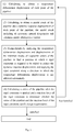
- A technical solution of the present disclosure resides in a design method for resisting a dynamic load in a high temperature pipeline, and the design method comprises the following steps: (1) calculating to obtain a temperature deformation displacement of each point of the pipeline; (2) calculating to obtain a modal result of the pipeline and a dynamic response displacement of each point of the pipeline, the modal result including all necessary natural frequencies and vibration modes of respective orders; (3) comprehensively analyzing the temperature deformation displacement and displacements of the vibration modes of respective orders of the pipeline to find a position at which a rigid constraint is required to be added to reduce the dynamic response displacement, and applying the rigid constraint along a direction in which the temperature deformation displacement is not affected substantially; and (4) calculating a stress of the pipeline after the rigid constraint is applied and a reaction force of the rigid constraint to determine whether the stress of the pipeline and the reaction force of the rigid constraint satisfy design requirements.
- According to one aspect of the present disclosure, as mentioned in the above design method for resisting a dynamic load in a high temperature pipeline, a temperature deformation displacement diagram of a pipeline system is obtained in the step (1), and the temperature deformation displacement diagram is a three-dimensional graph including a magnitude and a direction of the temperature deformation displacement of each point of the pipeline.
- According to one aspect of the present disclosure, as mentioned in the above design method for resisting a dynamic load in a high temperature pipeline, the dynamic response displacement in the step (3) is a combination of the displacements of the vibration modes of respective orders.
- According to one aspect of the present disclosure, as mentioned in the above design method for resisting a dynamic load in a high temperature pipeline, the position at which the rigid constraint is required to be added in the step (3) is a position where a direction of the dynamic response displacement does not coincide with a direction of the temperature deformation displacement.
- According to one aspect of the present disclosure, as mentioned in the above design method for resisting a dynamic load in a high temperature pipeline, in the step (3), the rigid constraint is applied in a plane perpendicular to a direction of the temperature deformation displacement.
- According to one aspect of the present disclosure, when it is determined that the stress of the pipeline or the reaction force of the rigid constraint does not satisfy the design requirements in the step (4), returning to the step (1) for redesign.
- According to one aspect of the present disclosure, in the step (3), a plurality of rigid constraints are applied at one position where the temperature deformation displacement is not affected substantially, and a direction in which a resultant force of the plurality of rigid constraints is exerted on the pipeline is perpendicular to a direction of the temperature deformation displacement at the one position of the pipeline.
- According to one aspect of the present disclosure, in the step (3), a plurality of rigid constraints are applied at each of a plurality of positions where the temperature deformation displacement is not affected substantially, and a direction in which a resultant force of the plurality of rigid constraints is exerted on the pipeline is perpendicular to a direction of the temperature deformation displacement at each position of the pipeline.
- According to one aspect of the present disclosure, the dynamic load is a seismic load, the rigid constraint is a hinged beam, and a unidirectional compressive or tensile force is only generated in the hinged beam by the pipeline under the seismic load.
- According to one aspect of the present disclosure, two rigid constraints with an intersection angle of 90 degrees are applied along a direction in which an angle of about 45 degrees is formed relative to the pipeline in a plane perpendicular to a direction of the temperature deformation displacement.
- According to one aspect of the present disclosure, when the rigid constraint is installed, an installation position point of the rigid constraint on a building structure is moved in advance by a predetermined amount in a direction of the temperature deformation displacement.
- The advantageous effects of the present disclosure are as follows: a principle of temperature deformation and a principle of deformation under a seismic load of a pipeline is considered in the present disclosure, theoretical knowledge of these aspects is also put into overall consideration according to characteristics of a rigid constraint, and a correct rigid constraint is applied at a correct position in a correct direction to resist a dynamic load. In this way, a pipeline support design that satisfies both a temperature stress and a seismic stress can be obtained. This arrangement can avoid or reduce the use of snubbers, thereby significantly reducing an investment in power plants or other engineering pipeline constructions having antiseismic requirements.
-
-
Fig. 1 is a flow diagram showing a design method for resisting a dynamic load in a high temperature pipeline; -
Fig. 2 is a schematic diagram showing a deformation (within an XY plane) of an intersection point of two straight pipelines when only temperature is considered; -
Fig. 3 is a schematic diagram showing application of two rigid brackets at a point a in the two straight pipelines as shown inFig. 2 in an embodiment; and -
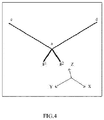
Fig. 4 is a three-dimensional schematic diagram showing the pipelines and the brackets as shown inFig. 3 . - The present disclosure will be described in detail below in connection with accompanying drawings and embodiments.
- A technical principle adopted in the present disclosure is that a temperature stress is generated by a temperature deformation being subject to a constraint, while the temperature deformation necessarily has a definite direction. In arranging a pipeline, as long as the constraint is released in a temperature deformation direction, a large temperature stress will not be generated. In principle, application of a constraint in a direction perpendicular to the temperature deformation will not have a significant influence on the temperature stress. Therefore, it is necessary to find the temperature deformation displacement under a specific pipeline arrangement, and such deformation displacement ought to be a deformation displacement of each point having a definite direction and a definite magnitude. After that, where the maximum internal force or the maximum internal moment in dynamic results is located and which vibration modes caused the largest result are analyzed, and then a position at which the rigid constraint is to be applied is determined by comprehensively considering a situation of the temperature stress according to a deformation and displacement of the vibration modes. This rigid constraint should not restrict the temperature deformation displacement at this position, that is, the constraint should be applied as much as possible in a direction perpendicular to the temperature displacement direction.
- A principle of dynamic response of a structure is described below so that a relationship between vibration modes and a final dynamic response can be seen. First, a dynamic equation of the structure is as follows:

- Wherein, M represents a mass of the structure, C represents a damping of the structure, K represents a rigidity of the structure, U represents nodal displacements of the structure, and Ï(t) represents a basic acceleration time history of the structure.
- By solving an undamped natural vibration, vibration modes Φ1, Φ2, ..., Φn-1, Φn with the number of n can be obtained.
- Simplified from equation (1), the following equation will be obtained, wherein ωi is a natural circular frequency of the i-th order of the structure:

- The maximum value of vibration mode responses can be derived from a theory of seismic force:

- In this equation, βix -- dynamic amplification factor, a value of βix when

kox --g-level acceleration coefficient, which is a seismic coefficient in case of earthquake, and is determined by a seismic intensity,
wherein δox =[1 0 0 0 0 0 1 0 0 0 0 0 1 0 0......1 0 0 0 0 0] T
wherein βix is the dynamic amplification factor, which is given by a seismic response spectrum, and is actually an acceleration coefficient. - A combination of the vibration mode responses can be obtained in the following manner:

- NF here indicates meaningful vibration modes with the number of NF of the structure, U is the dynamic response of the structure, and this equation means that a total response of the structure is a combined result of the vibration modes of respective orders. There are many methods for acquiring a combination of the vibration mode response of the structure, and an influence of dense frequencies (if a difference between frequencies of the two vibration modes is less than 10%, the two frequencies are regarded to be dense) is generally required to be considered. Different regulations or requirements involve different methods of combining the dense frequencies. The present disclosure only gives a method of marking dense frequencies, and a specific combination method is considered in accordance with the regulations or requirements adopted.
- The formula (3) here is fundamental, because the subsequent calculations are based on this formula which represents the most important relationship of a seismic response. That is, the response q of the structure is inversely proportional to the square of the natural circular frequency ω of the structure and is also directly proportional to a response spectrum acceleration. Main conditions for obtaining a seismic response displacement (dynamic response displacement) of the pipeline include natural frequencies of the pipeline and the response spectrum acceleration, and are also relevant to the vibration modesφi of respective orders. The dynamic response displacement is a function of a sum of displacements of the vibration modes of respective orders, which can be seen from the formula (4) in respect of the displacement U.
- The following three points can be seen: firstly, the larger the response spectrum acceleration is, the larger the response of the structure is, and they are in a linear relationship; secondly, the lowest frequency produces the greatest influence, that is, the higher frequency produces the smaller influence, and they are in inverse proportion to each other at a ratio of the second power. As a result, only the frequencies of several lower orders (for example, the first to third orders) needs to be considered, and the influence of frequencies of higher orders can be ignored; thirdly, the response of the structure is relevant to the displacements of the vibration modes φi of respective orders, and the response of the structure is mainly in direct proportion to the sum of respective vibration modes φi in lower frequencies. In this way, the position at which the rigid constraint should be applied to effectively reduce the seismic stress can be determined.
- As shown in
Fig. 1 , in the present disclosure, a temperature deformation displacement of each point of a pipeline is first calculated in a step (1), in which a temperature deformation displacement diagram of a pipeline system is obtained, and the temperature deformation displacement diagram here is a three-dimensional graph including a direction and a magnitude of the temperature deformation displacement of each point of the pipeline. Then, a modal result of the pipeline and a dynamic response displacement of each point of the pipeline (i.e., a seismic response displacement) are calculated in a step (2), and the modal result include all necessary natural frequencies and vibration modes of respective orders. After that, a seismic analysis is performed in a step (3) to find a position where a seismic stress or a seismic response displacement is too large and find a position and a direction at/in which a rigid constraint can be effectively applied so as to reduce the seismic stress or the seismic response displacement. At this time, it is necessary to comprehensively analyze the temperature deformation so that the temperature deformation displacement is not restricted or less-restricted (is not affected substantially) when a seismic constraint is applied. In other words, the position at which the rigid constraint is required to be added in the step (3) can not be a position where a direction of the seismic response displacement fully coincides with a direction of the temperature deformation displacement. When a rigid hinged beam bracket is used as a constraint, it should not be simply added directly to a position where only the seismic response displacement is to be constrained. Meanwhile, it is necessary not to restrict the temperature deformation displacement as much as possible, and applying the rigid constraint in a plane perpendicular to a direction of the temperature deformation displacement will not affect the temperature deformation displacement. For example, in a case where a temperature deformation of a certain point is in an X direction, the temperature deformation will not be restricted if the rigid constraint is added within a YZ plane at this time. For a complicated pipeline, as long as the temperature is unitary, the temperature deformation direction of each point of the pipeline is unique, that is, the deformation has only a different magnitude caused by the temperature which is high or low but is constant in the direction. It is easy to determine the position where the seismic stress or the seismic response displacement is large, and it is also easy to find the vibration mode that causes a large seismic stress or a large seismic response displacement through a vibration mode analysis. According to these conditions, in the step (3), the temperature deformation displacement of the pipeline is comprehensively considered, the rigid constraint is applied at a position where the temperature deformation displacement is not affected substantially, and the direction in which the rigid constraint is applied is perpendicular to the direction of the temperature deformation displacement. However, contribution to reduce the seismic displacement should also be taken into account. It is to be noted that this contribution may not be so direct and the contribution of the rigid constraint in its constraining direction may be reduction of a seismic deformation at other positions of the pipeline. Finally, a stress of the pipeline after the rigid constraint is applied and a reaction force of the rigid constraint are calculated in a step (4) so as to determine whether the stress of the pipeline and the reaction force of the rigid constraint satisfy design requirements. Due to the added rigid constraint, a whole model of the pipeline is changed, the vibration modes and the seismic response displacement at this time are necessarily changed, and the temperature deformation displacement will also be affected. Calculation for the modified model will result in a temperature deformation and a seismic deformation under a new condition. If a result of a new model is still not satisfactory, that is, when it is determined that the stress of the pipeline after the rigid constraint is applied and the reaction force of the rigid constraint do not meet the design requirements in the step (4), the same method can be used to modify the design and make reanalysis from the step (1), as shown inFig. 1 . - In one embodiment, in the step (3), a plurality of rigid constraints are applied at one position where the temperature deformation displacement is not affected substantially, and a direction in which a resultant force of the plurality of rigid constraints is exerted on the pipeline is perpendicular to the direction of the temperature deformation displacement at the one position of the pipeline.
- In one embodiment, in the step (3), a plurality of rigid constraints are applied at each of a plurality of positions where the temperature deformation displacement is not affected substantially, and a direction in which a resultant force of the plurality of rigid constraints is exerted on the pipeline is perpendicular to the direction of the temperature deformation displacement at each position of the pipeline.
- As described above, the number of the plurality of rigid constraints applied at the one position or each of the plurality of positions where the temperature deformation displacement is not affected substantially are at least two, and generally two rigid constrains can meet engineering requirements, of course, three, four or more rigid constrains may also be provided. By providing at least two hinged beams at each position, it can be ensured that the temperature deformation displacement of the pipeline perpendicular to the constraining direction is not affected by the rigid constraint, and it can be ensured that the constraint exerted on the pipeline is a bi-directional constraint in a plane formed by the two hinged beams, the bi-directional constraint being capable of resisting a dynamic load.
- In one embodiment, the dynamic load is a seismic load, each rigid constraint is a hinged beam, and only a unidirectional compressive or tensile force is produced in the hinged beam by the pipeline under the seismic load.
- For example, the hinged beam that is commonly used as a rigid constraint in engineering may be a bracket with pins on both ends, and the hinged beam only provides a one-way constraint along an axial direction of the hinge beam without applying a rotational constraint to the pipeline, i.e., the pipeline is rotatable relative to the hinged beam. In addition, a spherical hinged beam or a spherical hinged bracket can also be used as a connection form for ends of the rigid constraint in the present application.
- Actual engineering effects of the present disclosure will be described below in connection with the accompanying drawings and the embodiments.
Fig. 2 and Fig. 3 are top views in a XY plane (a horizontal plane), wherein a Z-axis direction is perpendicular to a plane in which the paper is present (called as a paper plane below) and is directed to an outter side of the paper plane.FIG. 4 is a three-dimensional perspective view showing that a direction in which the rigid constraints are applied is not in the horizontal plane, wherein the Z-axis direction obliquely intersects the paper plane and is directed to an inner side of the paper plane. -
Fig. 2 shows an assumed pipeline arrangement. Due to an effect of the temperature load, a large temperature deformation is produced in the pipeline. An intersection point of two straight pipelines ac and ad will be deformed from a point a to a point b. InFig. 2 , both of the two straight pipelines ac and ad are located in the horizontal plane (the paper plane), and the temperature deformation displacement of the intersection point of the pipelines is a displacement vector directed from the point a to the point b in the paper plane. The displacement vector is also referred to as a temperature deformation displacement line hereinafter. If the pipelines are so arranged, the maximum seismic deformation will be in a direction perpendicular to the paper plane (a Z-direction), the maximum seismic stress will occur at roots on both ends of each of the pipelines, and the vibration displacement is expected to be in the Z-direction (a vertical direction). At this time, the problem can be solved if a rigid constraint is applied in the Z-direction at the point a. However, considering that the seismic displacement of the pipeline is multi-directional, if the temperature is high or the pipeline is long, the temperature deformation will be large, in this case, it is not enough to apply the rigid support only in one direction because the vibration in the horizontal direction is not restricted. For adding a constraint in a horizontal direction, it is common to install a snubber, because the temperature deformation displacement can not be limited excessively but the vibration displacement should be restricted. Through the foregoing principle analysis and the method analysis of the present disclosure, as shown inFig. 4 , two rigid constraints g1 and g2 with an intersection angle of 90 degrees are applied along a direction in which an angle of about 45 degrees is formed relative to the pipelines ac and ad respectively in a plane perpendicular to the temperature deformation displacement line shown inFig. 2 (i.e., in a plane perpendicular to the paper plane or the horizontal plane). That is, the rigid constraints g1 and g2 extend in a direction oblique to the horizontal plane, projections of vectors of directions in which the rigid constraints g1 and g2 are applied in the paper plane (the XY plane) form an angle of about 45 degrees (a planar angle in the XY plane) with respect to the pipelines ac and ad respectively, and the two rigid constraints g1 and g2 form an angle of 90 degrees each other (a spatial angle rather than a planar angle). In order not to affect the temperature deformation displacement of the pipelines, it is necessary to cause a direction in which a resultant force of the two rigid constraints g1 and g2 is exerted on the intersection point a of the two pipelines to be substantially perpendicular to the direction of the temperature deformation displacement at that point. It should be pointed out that the same effect can be achieved by using angles other than 90 degrees as the intersection angle of the two rigid constraints g1 and g2. In this way, not only the vertical displacement is restricted, but also the horizontal displacement is restricted, while the temperature deformation is not restricted, which satisfies the requirements for both the temperature operating conditions and the seismic operating conditions. Moreover, the use of rigid supports is much more economical than use of snubbers. - Typically, a rigid constraint is installed at a position at which the antiseismic rigidity is required to be increased in the pipeline, and the rigid constraint is rooted in (fixed to) a building structure of a room in which the pipeline is located. In one embodiment, as shown in
FIG. 3 , when the rigid constraints are installed, an installation position point of the rigid constraints g1 and g2 on the building can be first moved in advance by a predetermined amount in the temperature deformation displacement direction (from a to b) in a plane parallel to the XY plane, and then the rigid constraints g1 and g2 are installed at the installation position point. Thus, when a deformation node on the pipelines is deformed from a displacement initial point a to a maximum displacement point b, the stress of the pipeline after the rigid constraints are applied and the reaction force of the rigid constraints are reduced as compared with a case where the installation position of the rigid constraints is not moved in advance, and it can also be ensured that the influence of the rigid constraints on the temperature deformation displacements of the pipelines is smaller. The predetermined amount may be 1/2, 1/3, 1/4 etc., of the maximum displacement amount from a to b shown inFig. 2 . - It is to be noted that the above specific embodiments are merely exemplary, and various improvements and modifications made by a person skilled in the art based on the above embodiments under an inspiration from the present disclosure fall within the scope of the present patent. It is to be understood by the person skilled in the art that the above concrete description is just for explanation purpose and is not intended to limit the scope of the present disclosure. The scope of the present disclosure is defined by the claims and their equivalents.
Claims (11)
- A design method for resisting a dynamic load in a high temperature pipeline, comprising the following steps:(1) calculating to obtain a temperature deformation displacement of each point of the pipeline (ac, ad);(2) calculating to obtain a modal result of the pipeline (ac, ad) and a dynamic response displacement of each point of the pipeline (ac, ad), the modal result including all necessary natural frequencies and vibration modes of respective orders;(3) comprehensively analyzing the temperature deformation displacement and displacements of the vibration modes of respective orders of the pipeline (ac, ad) to find a position at which a rigid constraint (g1, g2) is required to be added to reduce the dynamic response displacement, and applying the rigid constraint (g1, g2) along a direction in which the temperature deformation displacement is not affected substantially; and(4) calculating a stress of the pipeline (ac, ad) after the rigid constraint (g1, g2) is applied and a reaction force of the rigid constraint (g1, g2) to determine whether the stress of the pipeline (ac, ad) and the reaction force of the rigid constraint (g1, g2) satisfy design requirements.
- The design method for resisting a dynamic load in a high temperature pipeline according to claim 1, wherein a temperature deformation displacement diagram of the pipeline (ac, ad) is obtained in the step (1), and the temperature deformation displacement diagram is a three-dimensional graph including a magnitude and a direction of the temperature deformation displacement of each point of the pipeline (ac, ad).
- The design method for resisting a dynamic load in a high temperature pipeline according to claim 1, wherein the dynamic response displacement in the step (3) is a combination of the displacements of the vibration modes of respective orders.
- The design method for resisting a dynamic load in a high temperature pipeline according to claim 1, wherein the position at which the rigid constraint (g1, g2) is required to be added in the step (3) is a position where a direction of the dynamic response displacement does not coincide with a direction of the temperature deformation displacement.
- The design method for resisting a dynamic load in a high temperature pipeline according to claim 1, wherein in the step (3), the rigid constraint (g1, g2) is applied in a plane perpendicular to a direction of the temperature deformation displacement.
- The design method for resisting a dynamic load in a high temperature pipeline according to any one of claims 1 to 5, wherein when it is determined that the stress of the pipeline (ac, ad) or the reaction force of the rigid constraint (g1, g2) does not meet the design requirements in the step (4), returning to the step (1) for redesign.
- The design method for resisting a dynamic load in a high temperature pipeline according to any one of claims 1 to 5, wherein in the step (3), a plurality of rigid constraints (g1, g2) are applied at one position (a) where the temperature deformation displacement is not affected substantially, and a direction in which a resultant force of the plurality of rigid constraints is exerted on the pipeline is perpendicular to a direction of the temperature deformation displacement at the one position (a) of the pipeline (ac, ad).
- The design method for resisting a dynamic load in a high temperature pipeline according to any one of claims 1 to 5, wherein in the step (3), a plurality of rigid constraints (g1, g2) are applied at each (a) of a plurality of positions where the temperature deformation displacement is not affected substantially, and a direction in which a resultant force of the plurality of rigid constraints is exerted on the pipeline is perpendicular to a direction of the temperature deformation displacement at each position (a) of the pipeline (ac, ad).
- The design method for resisting a dynamic load in a high temperature pipeline according to any one of claims 1 to 5, wherein the dynamic load is a seismic load, the rigid constraint (g1, g2) is a hinged beam, and a unidirectional compressive or tensile force is only generated in the hinged beam by the pipeline (ac, ad) under the seismic load.
- The design method for resisting a dynamic load in a high temperature pipeline according to claim 5, wherein two rigid constraints (g1, g2) with an intersection angle of 90 degrees are applied along a direction in which an angle of about 45 degrees is formed relative to the pipeline (ac, ad) in a plane perpendicular to a direction of the temperature deformation displacement.
- The design method for resisting a dynamic load in a high temperature pipeline according to any one of claims 1 to 5, wherein when the rigid constraint (g1, g2) is installed, an installation position point of the rigid constraint (g1, g2) on a building structure is moved in advance by a predetermined amount in a direction of the temperature deformation displacement.
Applications Claiming Priority (1)
| Application Number | Priority Date | Filing Date | Title |
|---|---|---|---|
| CN201710834417.1A CN107688718B (en) | 2017-09-15 | 2017-09-15 | Design method for avoiding using damper to resist dynamic load of high-temperature pipeline |
Publications (2)
| Publication Number | Publication Date |
|---|---|
| EP3457305A1 true EP3457305A1 (en) | 2019-03-20 |
| EP3457305B1 EP3457305B1 (en) | 2025-04-02 |
Family
ID=61156469
Family Applications (1)
| Application Number | Title | Priority Date | Filing Date |
|---|---|---|---|
| EP18193826.7A Active EP3457305B1 (en) | 2017-09-15 | 2018-09-11 | A method for installing rigid constraints for reducing the use of snubbers in a high temperature pipeline |
Country Status (4)
| Country | Link |
|---|---|
| US (1) | US11087040B2 (en) |
| EP (1) | EP3457305B1 (en) |
| CN (1) | CN107688718B (en) |
| AR (1) | AR113051A1 (en) |
Cited By (5)
| Publication number | Priority date | Publication date | Assignee | Title |
|---|---|---|---|---|
| CN110110368A (en) * | 2019-04-03 | 2019-08-09 | 青岛理工大学 | Anti-seismic vibration mode number selection method based on vertex displacement and bottom shear force double indexes |
| CN113591267A (en) * | 2021-06-17 | 2021-11-02 | 东风汽车集团股份有限公司 | Analysis method and device for suspension strength of gearbox shell |
| CN114417228A (en) * | 2021-12-29 | 2022-04-29 | 中煤科工集团武汉设计研究院有限公司 | Method for calculating additional load of coal slurry pipeline caused by temperature difference and support displacement |
| CN116050206A (en) * | 2022-12-28 | 2023-05-02 | 中航油彭州管道运输有限公司 | A Method for Determining the Location of Stress and Vibration Detection Devices for Vehicle Rolled Aviation Fuel Pipelines |
| CN119939984A (en) * | 2024-12-19 | 2025-05-06 | 本钢板材股份有限公司 | A method for analyzing the crushing performance of automobile front longitudinal beam |
Families Citing this family (9)
| Publication number | Priority date | Publication date | Assignee | Title |
|---|---|---|---|---|
| CN109902439B (en) * | 2019-03-25 | 2023-01-13 | 东北大学 | Aeronautical power generation pipeline modeling and vibration characteristic analysis method considering bolt connection |
| CN112329157A (en) * | 2019-07-31 | 2021-02-05 | 深圳市建筑设计研究总院有限公司 | A Loading and Internal Force Calculation Method for Secondary Internal Force Structures |
| CN111924331B (en) * | 2020-07-16 | 2022-02-08 | 燕山大学 | Method and system for optimizing vertical bracket structure in steel coil transportation and standing process |
| CN112628469B (en) * | 2020-11-24 | 2022-11-11 | 中国核电工程有限公司 | Design method of double support rods for applying rigid constraint to pipeline and pipeline structure |
| CN112818444B (en) * | 2021-01-15 | 2022-12-30 | 中铁二院工程集团有限责任公司 | Railway concrete bridge linear real-time control method based on operation and driving safety |
| CN114329816B (en) * | 2021-11-30 | 2025-06-17 | 北京动力机械研究所 | A method for optimizing the preload force of the shaft nut of a rotor system considering the influence of thermal deformation |
| CN114738589B (en) * | 2022-04-14 | 2023-08-04 | 中国核电工程有限公司 | Nuclear grade pipeline bracket setting method and device |
| CN115265650A (en) * | 2022-07-15 | 2022-11-01 | 中铁第四勘察设计院集团有限公司 | Detection system and method for pipeline magnetic suspension traffic |
| CN119203693B (en) * | 2024-11-27 | 2025-03-28 | 哈尔滨工业大学(威海) | A method for calculating the pointing accuracy of radio telescopes under structural deformation |
Citations (1)
| Publication number | Priority date | Publication date | Assignee | Title |
|---|---|---|---|---|
| EP0349014A2 (en) * | 1984-02-21 | 1990-01-03 | Stone & Webster Engineering Corporation | Support structure for a nuclear reactor |
Family Cites Families (23)
| Publication number | Priority date | Publication date | Assignee | Title |
|---|---|---|---|---|
| US4110731A (en) * | 1976-12-30 | 1978-08-29 | Bell & Howell Company | Vibration transducer with improved viscous damping |
| US4266287A (en) * | 1979-04-16 | 1981-05-05 | Bell & Howell Company | Transducer systems with controlled damping |
| US4909981A (en) * | 1984-02-21 | 1990-03-20 | Stone & Webster Engineering Corporation | Nuclear reactor |
| US4761261A (en) * | 1984-02-21 | 1988-08-02 | Stone & Webster Engineering Corp. | Nuclear reactor |
| US4832305A (en) * | 1986-04-15 | 1989-05-23 | Wyle Laboratories | Equipment support system |
| JPS63231233A (en) * | 1987-03-20 | 1988-09-27 | Hitachi Ltd | Vibration response analysis method |
| FR2842206B1 (en) * | 2002-07-11 | 2007-03-23 | Inst Francais Du Petrole | COMPOSITIONS FOR NEW COATINGS FOR HIGH TEMPERATURE PIPES |
| US20100059230A1 (en) * | 2008-09-05 | 2010-03-11 | Harold Brian Skeels | Coil tubing guide |
| CN201568641U (en) * | 2010-01-04 | 2010-09-01 | 山东电力研究院 | Devices to limit the displacement of horizontal pipes |
| CN101800464B (en) * | 2010-01-28 | 2011-11-09 | 清华大学 | Sealing and driving device in high-temperature gas-cooled reactor helium gas space and driving device thereof |
| WO2012135683A1 (en) * | 2011-03-30 | 2012-10-04 | Ambature Llc | Electrical, mechanical, computing, and/or other devices formed of extremely low resistance materials |
| CN102147105B (en) * | 2011-04-11 | 2012-11-21 | 中国华能集团清洁能源技术研究院有限公司 | Arrangement structure of inverted pulverized-coal fired boiler suitable for ultra-high steam temperature steam parameters |
| US8825453B2 (en) * | 2011-11-22 | 2014-09-02 | Fluor Technologies Corporation | Piping analysis systems |
| MY186398A (en) * | 2012-06-29 | 2021-07-22 | Petroliam Nasional Berhad Petronas | Lining of pipelines to offshore installations |
| JP6076466B2 (en) * | 2013-04-02 | 2017-02-08 | 三菱電機株式会社 | Power converter and refrigeration air conditioner |
| CN104264054B (en) * | 2014-09-19 | 2017-02-22 | 宝山钢铁股份有限公司 | 550MPa-level high-temperature resistant pipeline steel and preparation method thereof |
| EP3213612A4 (en) * | 2014-10-31 | 2018-09-19 | Algozen Corporation | A mounting apparatus, for mounting at least one heat dissipating electrical device, optionally including a heat sink body for solid, gas and fluid heat exchange, and circuit board assembly providing interface between circuits |
| RU2583324C1 (en) * | 2014-12-12 | 2016-05-10 | Открытое акционерное общество "Ордена Трудового Красного Знамени и ордена труда ЧССР опытное конструкторское бюро "ГИДРОПРЕСС" (ОАО ОКБ "ГИДРОПРЕСС") | Horizontal steam generator for reactor plant with water-cooled power reactor and reactor plant with said steam generator |
| CN104504226B (en) * | 2015-01-25 | 2017-10-27 | 中南大学 | The supporting of fluid conveying pipe antivibration and its design method under a kind of strong vibration environment |
| EP3059485A1 (en) * | 2015-02-17 | 2016-08-24 | J. van Beugen Beheer B.V. | Metal pipes with anticorrosive polyolefin covering layer |
| CN107532953A (en) * | 2015-03-31 | 2018-01-02 | 株式会社NejiLaw | The part in band-pass circuit footpath and the patterning method of electrical path and component change measuring method |
| CN106870441B (en) * | 2015-12-11 | 2019-01-15 | 中广核工程有限公司 | Nuclear power station main pump axle envelope injects water system |
| CN106337941B (en) * | 2016-10-10 | 2018-08-03 | 中国矿业大学 | A kind of heat dissipation pressure reducing valve certainly |
-
2017
- 2017-09-15 CN CN201710834417.1A patent/CN107688718B/en active Active
-
2018
- 2018-09-11 AR ARP180102576A patent/AR113051A1/en active IP Right Grant
- 2018-09-11 EP EP18193826.7A patent/EP3457305B1/en active Active
- 2018-09-14 US US16/131,804 patent/US11087040B2/en active Active
Patent Citations (1)
| Publication number | Priority date | Publication date | Assignee | Title |
|---|---|---|---|---|
| EP0349014A2 (en) * | 1984-02-21 | 1990-01-03 | Stone & Webster Engineering Corporation | Support structure for a nuclear reactor |
Non-Patent Citations (4)
| Title |
|---|
| FABRIZIO PAOLACCI ET AL: "SEISMIC ANALYSIS AND COMPONENT DESIGN OF REFINERY PIPING SYSTEMS", COMPDYN 2011 III ECCOMAS THEMATIC CONFERENCE ON COMPUTATIONAL METHODS IN STRUCTURAL DYNAMICS AND EARTHQUAKE ENGINEERING, 25 May 2011 (2011-05-25), pages 25 - 28, XP055549284, Retrieved from the Internet <URL:http://congress.cimne.com/eccomas/proceedings/compdyn2011/compdyn2011_full/360.pdf> [retrieved on 20190130] * |
| JUNWEI WANG: "THE ANALYSIS OF EFFECT ON THE PIPING DUE TO THE DISPLACEMENT OF EPR NUCLEAR ISLAND BULIDINGS", PROCEEDINGS OF THE 18TH INTERNATIONAL CONFERENCE ON NUCLEAR ENGINEERING ICONE18 MAY 17-21, 17 May 2010 (2010-05-17), pages 1 - 6, XP055549291 * |
| K V SUBRAMANIAN: "EVOLUTION OF SEISMIC DESIGN OF STRUCTURES, SYSTEMS AND COMPONENTS OF NUCLEAR POWER PLANTS", ISET JOURNAL OF EARTHQUAKE TECHNOLOGY, 2 June 2010 (2010-06-02), pages 87 - 108, XP055549055, Retrieved from the Internet <URL:http://home.iitk.ac.in/~vinaykg/Iset512.pdf> [retrieved on 20190129] * |
| RUI LIU ET AL: "Application of Peps in Stress Analysis of Nuclear Piping", JOURNAL OF APPLIED MATHEMATICS AND PHYSICS, vol. 01, no. 06, 1 November 2013 (2013-11-01), pages 57 - 61, XP055549057, ISSN: 2327-4352, DOI: 10.4236/jamp.2013.16012 * |
Cited By (8)
| Publication number | Priority date | Publication date | Assignee | Title |
|---|---|---|---|---|
| CN110110368A (en) * | 2019-04-03 | 2019-08-09 | 青岛理工大学 | Anti-seismic vibration mode number selection method based on vertex displacement and bottom shear force double indexes |
| CN110110368B (en) * | 2019-04-03 | 2021-12-21 | 青岛理工大学 | Anti-seismic vibration mode number selection method based on vertex displacement and bottom shear force double indexes |
| CN113591267A (en) * | 2021-06-17 | 2021-11-02 | 东风汽车集团股份有限公司 | Analysis method and device for suspension strength of gearbox shell |
| CN113591267B (en) * | 2021-06-17 | 2023-12-19 | 东风汽车集团股份有限公司 | An analysis method and device for gearbox housing suspension strength |
| CN114417228A (en) * | 2021-12-29 | 2022-04-29 | 中煤科工集团武汉设计研究院有限公司 | Method for calculating additional load of coal slurry pipeline caused by temperature difference and support displacement |
| CN114417228B (en) * | 2021-12-29 | 2022-10-11 | 中煤科工集团武汉设计研究院有限公司 | Method for calculating additional load of coal slurry pipeline caused by temperature difference and support displacement |
| CN116050206A (en) * | 2022-12-28 | 2023-05-02 | 中航油彭州管道运输有限公司 | A Method for Determining the Location of Stress and Vibration Detection Devices for Vehicle Rolled Aviation Fuel Pipelines |
| CN119939984A (en) * | 2024-12-19 | 2025-05-06 | 本钢板材股份有限公司 | A method for analyzing the crushing performance of automobile front longitudinal beam |
Also Published As
| Publication number | Publication date |
|---|---|
| AR113051A1 (en) | 2020-01-22 |
| US11087040B2 (en) | 2021-08-10 |
| US20190087528A1 (en) | 2019-03-21 |
| CN107688718B (en) | 2022-11-18 |
| CN107688718A (en) | 2018-02-13 |
| EP3457305B1 (en) | 2025-04-02 |
Similar Documents
| Publication | Publication Date | Title |
|---|---|---|
| EP3457305B1 (en) | A method for installing rigid constraints for reducing the use of snubbers in a high temperature pipeline | |
| Ryu et al. | Experimental study of large area suspended ceilings | |
| Connor et al. | Structural motion engineering | |
| Tse et al. | Performance and cost evaluation of a smart tuned mass damper for suppressing wind-induced lateral-torsional motion of tall structures | |
| CN101944140A (en) | Earthquake proof performance analysis method of dry type transformer for nuclear power | |
| Malekpour et al. | Direct displacement‐based design of steel‐braced reinforced concrete frames | |
| He et al. | A macro-level global seismic damage model considering higher modes | |
| Manoukas et al. | Evaluation of a multimode pushover procedure for asymmetric in plan buildings under biaxial seismic excitation | |
| JP2003132107A (en) | Piping device and method of designing piping device | |
| Terazawa et al. | Elasto-plastic damper optimization routine for lattice towers based on generalized response spectrum analysis | |
| Ohsaki et al. | Prediction of inelastic seismic responses of arch-type long-span structures using a series of multimodal pushover analyses | |
| Arunachalam et al. | A stochastic simulation scheme for the estimation of small failure probabilities in wind engineering applications | |
| CN119761103A (en) | A tower safety assessment method and system based on damage mechanism | |
| Aly | Design of buildings for wind and earthquake | |
| Deng et al. | Concise Analytic Solutions for Random Seismic Response of High‐Rise Structure With Series‐Parallel Inerter System and Tuned Mass Damper | |
| M Elmorsy et al. | Performance based seismic assessment of buildings with curved shear walls | |
| Akcelyan et al. | A practical method for seismic retrofit of tall buildings with supplemental damping | |
| CN112733226A (en) | Shore bridge damping coefficient calculation method, device, equipment and storage medium | |
| Wróblewski et al. | Parameter identification of steel-concrete composite beams by finite element method | |
| Kwag et al. | A Study on Application of Tuned Mass Damper to Piping System under Earthquake | |
| Wilbee et al. | Fragility analysis of structures incorporating control systems | |
| Faggella et al. | Graphical dynamic trends for earthquake incidence response of plan-asymmetric systems | |
| Makarios | The equivalent non-linear single degree of freedom system of asymmetric multi-storey buildings in seismic static pushover analysis | |
| Kuzucu | The nature of the vertical distribution of seismic responses in multi-story structures | |
| Bajoria et al. | Stability analysis of 3-D conventional pallet rack structures with semi-rigid connections |
Legal Events
| Date | Code | Title | Description |
|---|---|---|---|
| PUAI | Public reference made under article 153(3) epc to a published international application that has entered the european phase |
Free format text: ORIGINAL CODE: 0009012 |
|
| STAA | Information on the status of an ep patent application or granted ep patent |
Free format text: STATUS: THE APPLICATION HAS BEEN PUBLISHED |
|
| AK | Designated contracting states |
Kind code of ref document: A1 Designated state(s): AL AT BE BG CH CY CZ DE DK EE ES FI FR GB GR HR HU IE IS IT LI LT LU LV MC MK MT NL NO PL PT RO RS SE SI SK SM TR |
|
| AX | Request for extension of the european patent |
Extension state: BA ME |
|
| STAA | Information on the status of an ep patent application or granted ep patent |
Free format text: STATUS: REQUEST FOR EXAMINATION WAS MADE |
|
| 17P | Request for examination filed |
Effective date: 20190920 |
|
| RBV | Designated contracting states (corrected) |
Designated state(s): AL AT BE BG CH CY CZ DE DK EE ES FI FR GB GR HR HU IE IS IT LI LT LU LV MC MK MT NL NO PL PT RO RS SE SI SK SM TR |
|
| STAA | Information on the status of an ep patent application or granted ep patent |
Free format text: STATUS: EXAMINATION IS IN PROGRESS |
|
| 17Q | First examination report despatched |
Effective date: 20210929 |
|
| REG | Reference to a national code |
Ref country code: DE Ref legal event code: R079 Free format text: PREVIOUS MAIN CLASS: G06F0017500000 Ipc: G06F0030180000 Ref country code: DE Ref legal event code: R079 Ref document number: 602018080662 Country of ref document: DE Free format text: PREVIOUS MAIN CLASS: G06F0017500000 Ipc: G06F0030180000 |
|
| GRAP | Despatch of communication of intention to grant a patent |
Free format text: ORIGINAL CODE: EPIDOSNIGR1 |
|
| STAA | Information on the status of an ep patent application or granted ep patent |
Free format text: STATUS: GRANT OF PATENT IS INTENDED |
|
| RIC1 | Information provided on ipc code assigned before grant |
Ipc: G06F 111/04 20200101ALN20241106BHEP Ipc: G06F 119/14 20200101ALN20241106BHEP Ipc: G06F 119/08 20200101ALN20241106BHEP Ipc: G06F 113/14 20200101ALN20241106BHEP Ipc: G06F 111/10 20200101ALN20241106BHEP Ipc: G06F 30/17 20200101ALI20241106BHEP Ipc: G06F 30/20 20200101ALI20241106BHEP Ipc: G06F 30/18 20200101AFI20241106BHEP |
|
| INTG | Intention to grant announced |
Effective date: 20241115 |
|
| RIC1 | Information provided on ipc code assigned before grant |
Ipc: G06F 111/04 20200101ALN20241108BHEP Ipc: G06F 119/14 20200101ALN20241108BHEP Ipc: G06F 119/08 20200101ALN20241108BHEP Ipc: G06F 113/14 20200101ALN20241108BHEP Ipc: G06F 111/10 20200101ALN20241108BHEP Ipc: G06F 30/17 20200101ALI20241108BHEP Ipc: G06F 30/20 20200101ALI20241108BHEP Ipc: G06F 30/18 20200101AFI20241108BHEP |
|
| GRAS | Grant fee paid |
Free format text: ORIGINAL CODE: EPIDOSNIGR3 |
|
| GRAA | (expected) grant |
Free format text: ORIGINAL CODE: 0009210 |
|
| STAA | Information on the status of an ep patent application or granted ep patent |
Free format text: STATUS: THE PATENT HAS BEEN GRANTED |
|
| AK | Designated contracting states |
Kind code of ref document: B1 Designated state(s): AL AT BE BG CH CY CZ DE DK EE ES FI FR GB GR HR HU IE IS IT LI LT LU LV MC MK MT NL NO PL PT RO RS SE SI SK SM TR |
|
| REG | Reference to a national code |
Ref country code: GB Ref legal event code: FG4D |
|
| REG | Reference to a national code |
Ref country code: CH Ref legal event code: EP |
|
| P01 | Opt-out of the competence of the unified patent court (upc) registered |
Free format text: CASE NUMBER: APP_12093/2025 Effective date: 20250312 |
|
| REG | Reference to a national code |
Ref country code: IE Ref legal event code: FG4D |
|
| REG | Reference to a national code |
Ref country code: DE Ref legal event code: R096 Ref document number: 602018080662 Country of ref document: DE |
|
| REG | Reference to a national code |
Ref country code: SE Ref legal event code: TRGR |
|
| REG | Reference to a national code |
Ref country code: NL Ref legal event code: MP Effective date: 20250402 |
|
| PG25 | Lapsed in a contracting state [announced via postgrant information from national office to epo] |
Ref country code: NL Free format text: LAPSE BECAUSE OF FAILURE TO SUBMIT A TRANSLATION OF THE DESCRIPTION OR TO PAY THE FEE WITHIN THE PRESCRIBED TIME-LIMIT Effective date: 20250402 |
|
| REG | Reference to a national code |
Ref country code: AT Ref legal event code: MK05 Ref document number: 1781980 Country of ref document: AT Kind code of ref document: T Effective date: 20250402 |
|
| REG | Reference to a national code |
Ref country code: CH Ref legal event code: U11 Free format text: ST27 STATUS EVENT CODE: U-0-0-U10-U11 (AS PROVIDED BY THE NATIONAL OFFICE) Effective date: 20251001 |
|
| PG25 | Lapsed in a contracting state [announced via postgrant information from national office to epo] |
Ref country code: ES Free format text: LAPSE BECAUSE OF FAILURE TO SUBMIT A TRANSLATION OF THE DESCRIPTION OR TO PAY THE FEE WITHIN THE PRESCRIBED TIME-LIMIT Effective date: 20250402 Ref country code: FI Free format text: LAPSE BECAUSE OF FAILURE TO SUBMIT A TRANSLATION OF THE DESCRIPTION OR TO PAY THE FEE WITHIN THE PRESCRIBED TIME-LIMIT Effective date: 20250402 Ref country code: PT Free format text: LAPSE BECAUSE OF FAILURE TO SUBMIT A TRANSLATION OF THE DESCRIPTION OR TO PAY THE FEE WITHIN THE PRESCRIBED TIME-LIMIT Effective date: 20250804 |
|
| PGFP | Annual fee paid to national office [announced via postgrant information from national office to epo] |
Ref country code: DE Payment date: 20250922 Year of fee payment: 8 |
|
| REG | Reference to a national code |
Ref country code: LT Ref legal event code: MG9D |
|
| PG25 | Lapsed in a contracting state [announced via postgrant information from national office to epo] |
Ref country code: NO Free format text: LAPSE BECAUSE OF FAILURE TO SUBMIT A TRANSLATION OF THE DESCRIPTION OR TO PAY THE FEE WITHIN THE PRESCRIBED TIME-LIMIT Effective date: 20250702 Ref country code: GR Free format text: LAPSE BECAUSE OF FAILURE TO SUBMIT A TRANSLATION OF THE DESCRIPTION OR TO PAY THE FEE WITHIN THE PRESCRIBED TIME-LIMIT Effective date: 20250703 |
|
| PG25 | Lapsed in a contracting state [announced via postgrant information from national office to epo] |
Ref country code: PL Free format text: LAPSE BECAUSE OF FAILURE TO SUBMIT A TRANSLATION OF THE DESCRIPTION OR TO PAY THE FEE WITHIN THE PRESCRIBED TIME-LIMIT Effective date: 20250402 |
|
| PG25 | Lapsed in a contracting state [announced via postgrant information from national office to epo] |
Ref country code: BG Free format text: LAPSE BECAUSE OF FAILURE TO SUBMIT A TRANSLATION OF THE DESCRIPTION OR TO PAY THE FEE WITHIN THE PRESCRIBED TIME-LIMIT Effective date: 20250402 |
|
| PG25 | Lapsed in a contracting state [announced via postgrant information from national office to epo] |
Ref country code: HR Free format text: LAPSE BECAUSE OF FAILURE TO SUBMIT A TRANSLATION OF THE DESCRIPTION OR TO PAY THE FEE WITHIN THE PRESCRIBED TIME-LIMIT Effective date: 20250402 |
|
| PG25 | Lapsed in a contracting state [announced via postgrant information from national office to epo] |
Ref country code: AT Free format text: LAPSE BECAUSE OF FAILURE TO SUBMIT A TRANSLATION OF THE DESCRIPTION OR TO PAY THE FEE WITHIN THE PRESCRIBED TIME-LIMIT Effective date: 20250402 |
|
| PGFP | Annual fee paid to national office [announced via postgrant information from national office to epo] |
Ref country code: FR Payment date: 20250923 Year of fee payment: 8 |
|
| PGFP | Annual fee paid to national office [announced via postgrant information from national office to epo] |
Ref country code: SE Payment date: 20250923 Year of fee payment: 8 |
|
| PG25 | Lapsed in a contracting state [announced via postgrant information from national office to epo] |
Ref country code: RS Free format text: LAPSE BECAUSE OF FAILURE TO SUBMIT A TRANSLATION OF THE DESCRIPTION OR TO PAY THE FEE WITHIN THE PRESCRIBED TIME-LIMIT Effective date: 20250702 |
|
| PG25 | Lapsed in a contracting state [announced via postgrant information from national office to epo] |
Ref country code: IS Free format text: LAPSE BECAUSE OF FAILURE TO SUBMIT A TRANSLATION OF THE DESCRIPTION OR TO PAY THE FEE WITHIN THE PRESCRIBED TIME-LIMIT Effective date: 20250802 |
|
| PG25 | Lapsed in a contracting state [announced via postgrant information from national office to epo] |
Ref country code: LV Free format text: LAPSE BECAUSE OF FAILURE TO SUBMIT A TRANSLATION OF THE DESCRIPTION OR TO PAY THE FEE WITHIN THE PRESCRIBED TIME-LIMIT Effective date: 20250402 |
|
| REG | Reference to a national code |
Ref country code: DE Ref legal event code: R097 Ref document number: 602018080662 Country of ref document: DE |
|
| PG25 | Lapsed in a contracting state [announced via postgrant information from national office to epo] |
Ref country code: DK Free format text: LAPSE BECAUSE OF FAILURE TO SUBMIT A TRANSLATION OF THE DESCRIPTION OR TO PAY THE FEE WITHIN THE PRESCRIBED TIME-LIMIT Effective date: 20250402 Ref country code: SM Free format text: LAPSE BECAUSE OF FAILURE TO SUBMIT A TRANSLATION OF THE DESCRIPTION OR TO PAY THE FEE WITHIN THE PRESCRIBED TIME-LIMIT Effective date: 20250402 |
|
| PGFP | Annual fee paid to national office [announced via postgrant information from national office to epo] |
Ref country code: CH Payment date: 20251001 Year of fee payment: 8 |
|
| PG25 | Lapsed in a contracting state [announced via postgrant information from national office to epo] |
Ref country code: CZ Free format text: LAPSE BECAUSE OF FAILURE TO SUBMIT A TRANSLATION OF THE DESCRIPTION OR TO PAY THE FEE WITHIN THE PRESCRIBED TIME-LIMIT Effective date: 20250402 |
|
| PG25 | Lapsed in a contracting state [announced via postgrant information from national office to epo] |
Ref country code: EE Free format text: LAPSE BECAUSE OF FAILURE TO SUBMIT A TRANSLATION OF THE DESCRIPTION OR TO PAY THE FEE WITHIN THE PRESCRIBED TIME-LIMIT Effective date: 20250402 |
|
| PG25 | Lapsed in a contracting state [announced via postgrant information from national office to epo] |
Ref country code: SK Free format text: LAPSE BECAUSE OF FAILURE TO SUBMIT A TRANSLATION OF THE DESCRIPTION OR TO PAY THE FEE WITHIN THE PRESCRIBED TIME-LIMIT Effective date: 20250402 Ref country code: RO Free format text: LAPSE BECAUSE OF FAILURE TO SUBMIT A TRANSLATION OF THE DESCRIPTION OR TO PAY THE FEE WITHIN THE PRESCRIBED TIME-LIMIT Effective date: 20250402 |
|
| PG25 | Lapsed in a contracting state [announced via postgrant information from national office to epo] |
Ref country code: IT Free format text: LAPSE BECAUSE OF FAILURE TO SUBMIT A TRANSLATION OF THE DESCRIPTION OR TO PAY THE FEE WITHIN THE PRESCRIBED TIME-LIMIT Effective date: 20250402 |
|
| PLBE | No opposition filed within time limit |
Free format text: ORIGINAL CODE: 0009261 |
|
| STAA | Information on the status of an ep patent application or granted ep patent |
Free format text: STATUS: NO OPPOSITION FILED WITHIN TIME LIMIT |
|
| REG | Reference to a national code |
Ref country code: CH Ref legal event code: L10 Free format text: ST27 STATUS EVENT CODE: U-0-0-L10-L00 (AS PROVIDED BY THE NATIONAL OFFICE) Effective date: 20260211 |
|
| 26N | No opposition filed |
Effective date: 20260105 |