EP3457079B1 - Wear sensor - Google Patents
Wear sensor Download PDFInfo
- Publication number
- EP3457079B1 EP3457079B1 EP18192987.8A EP18192987A EP3457079B1 EP 3457079 B1 EP3457079 B1 EP 3457079B1 EP 18192987 A EP18192987 A EP 18192987A EP 3457079 B1 EP3457079 B1 EP 3457079B1
- Authority
- EP
- European Patent Office
- Prior art keywords
- wear
- polymeric material
- sensor
- vat
- connection
- Prior art date
- Legal status (The legal status is an assumption and is not a legal conclusion. Google has not performed a legal analysis and makes no representation as to the accuracy of the status listed.)
- Active
Links
Images


Classifications
-
- G—PHYSICS
- G01—MEASURING; TESTING
- G01B—MEASURING LENGTH, THICKNESS OR SIMILAR LINEAR DIMENSIONS; MEASURING ANGLES; MEASURING AREAS; MEASURING IRREGULARITIES OF SURFACES OR CONTOURS
- G01B21/00—Measuring arrangements or details thereof, where the measuring technique is not covered by the other groups of this subclass, unspecified or not relevant
- G01B21/02—Measuring arrangements or details thereof, where the measuring technique is not covered by the other groups of this subclass, unspecified or not relevant for measuring length, width, or thickness
- G01B21/08—Measuring arrangements or details thereof, where the measuring technique is not covered by the other groups of this subclass, unspecified or not relevant for measuring length, width, or thickness for measuring thickness
-
- G—PHYSICS
- G01—MEASURING; TESTING
- G01N—INVESTIGATING OR ANALYSING MATERIALS BY DETERMINING THEIR CHEMICAL OR PHYSICAL PROPERTIES
- G01N3/00—Investigating strength properties of solid materials by application of mechanical stress
- G01N3/56—Investigating resistance to wear or abrasion
Definitions
- the object of the present invention is a wear sensor for detecting the degree of wear of a polymeric material.
- the present invention has as object a radial wear sensor applicable to abrasion-resistant surface coatings such as vibratory-finishing vat coatings, grids and screens, rollers, kinematic chains for wear-resistant pumps and similar products.
- the pieces to be processed are placed in these vats and a reciprocal movement is imparted between the pieces and the finishing media contained in the vat.
- the vats generally have a metal bottom covered with a layer of wear-resistant polymer.
- This layer can wear up to the point where it no longer covers all or part of the metal bottom of the vat, which in turn is exposed to wear, and can even be perforated at certain points, with a consequent serious economic impact and impact on processing times. Similar problems may also occur in other industries where components made of or lined with polymeric material are used.
- the screening sector whether in stone quarries or in other types of mechanical screening or selection, makes extensive use of load-bearing or non-load-bearing polyurethane grids.
- rollers coated with polyurethane but also with other elastomers or polymers, for example in the field of coils rollers, in the steel sector.
- EP 0 637 697 A1 discloses a probe for indicating wear of a brake pad.
- a purpose of this invention is to provide a system that adequately monitors the level of wear of industrial components made of or lined with polymeric material.
- These components include vibratory finishing vats with bottoms covered with polymeric material, grids that can be used for screening or not, either in stone quarries or in other types of sieves or mechanical selections, on rollers covered with polyurethane, for example in the field of rollers for coils, in the steel sector, rotating bodies or pump bodies in polyurethane and similar elastomers and coatings of loading hoppers, weighing hoppers, unloading hoppers from mixing groups and all types of vats or silos and other applications.
- a system comprising an object or a coating made of polymeric material and a sensor for detecting the degree of wear of the object or of the coating made of polymeric material
- the sensor comprises a body made of polymeric material, said body being immersed in or covered by the polymeric material of which wear has to be measured, wherein said body has a plurality of reliefs each having an apex placed at a different height, and wherein a connection for each of the apexes is provided, the connection being configured when interrupted to signal to a control unit progressively more severe levels of wear when the wear of the polymeric material of the object or of the coating propagates to the respective apex of the sensor.
- An advantage of this solution is that it makes available a particular type of sensor, whose main function is to detect the level of wear of an elastomer or polymer coating of a metal or other polymer body, or of the body itself made entirely of elastomer or generally of polymeric material.
- this sensor is applied to the surface to be coated, for example to the bottom of a vibratory finishing vat or other industrial component.
- the vat can then be lined up to cover the sensor, even abundantly, immersing it in the polymeric material whose wear is to be measured.
- the apexes of the sensor body are arranged in such a way as to signal progressively more severe levels of wear to a control system, there is also the advantage that, depending on the connection to the control system that has been interrupted, a signal of slight, medium, severe or extreme wear is generated.
- connection with the control unit is an electrical connection between an apex of the sensor body and a control unit.
- An advantage of this solution is that the cable carries electricity.
- the interruption of the passage of electricity determines a change of state (e.g. from 1 to 0) indicating a particular condition of wear.
- connection to the control unit is an optical connection made via a fiberglass cable between an apex of the sensor body and a control unit.
- An advantage of this solution is that it avoids "polluting” by releasing heavy metals during the wear of the sensor connection.
- the interruption of the light passage causes a change in state (e.g. from 1 to 0), as in the previous case.
- connection to the control unit is a fluidic connection between an apex of the sensor body and the control unit.
- connection between a sensor body apex and the control unit is an inductive RFID connection or a wireless connection secured by a battery or a kinetic power source.
- the polymeric material of the sensor body is equal to the polymeric material of the coating or object whose wear is to be measured, or is a polymeric material having mechanical properties very similar to those of the polymeric material of the coating or object whose wear is to be measured.
- the hardness of the polymeric material of which the sensor is composed is equal to or slightly less than the hardness of the first polymeric material of which to measure wear It is necessary, in fact, that in the moment in which the coating - for example starting from 90 ShA of hardness - should begin to give way, the wearing material does not find a weak point in which to accelerate its action thanks to the sensor - for this reason the hardnesses must be possibly equivalent.
- vat for the containment of surface treatment media of pieces to be finished, where that vat includes a metal bottom, said bottom being covered with a coating of polymeric material, wherein the vat includes at least a wear sensor as described above, wherein the wear sensor is embedded in or covered by the coating of polymer material of the vat.
- wear sensors are arranged in the vat in a radial configuration where the lower apexes of the sensor body are oriented towards the center of the vat.
- This solution is designed precisely so that the area of the lower sensor is specially oriented towards the center of the vat towards which the vibration tends to wear out more the anti-abrasive coating.
- Another embodiment of the invention includes a load-bearing grid for screening or sieving stones or other mechanical selections, where the grid is made of or lined with polymeric material, where the grid includes at least a wear sensor embedded in or covered by the polymeric material.
- a further embodiment of the present invention involves a roller coated with polymeric material, where the roller includes at least one wear sensor embedded in or covered with the polymeric material.
- a further embodiment of this invention is a pump impeller casing where the impeller casing is made of polymeric material, where the impeller casing includes at least one wear sensor is embedded in or covered by the polymeric material.
- another embodiment of the invention includes a hopper made of or lined with polymeric material, where the hopper includes at least one wear sensor, where the wear sensor is embedded in or covered with the polymeric material.
- Figure 1 illustrates a first embodiment of the present invention, globally indicated by numerical reference 10.
- Sensor 10 is configured to detect the degree of wear of an object or of a polymer coating 30.
- Non-limitative examples of such polymeric objects or coatings may be polymeric coatings for vibratory finishing vats, for load-bearing grids for screening or not for screening.
- polymeric materials derive from the polymerisation reaction of a quantity of basic molecules (monomers) to form even very long chains.
- a polymeric material is generally composed of macromolecules consisting of the same type of repetitive unit.
- polymeric materials include polyurethanes, elastomers such as silicone rubbers and rubbers, and other polymers.
- sensor 10 includes a body 20 made of polymeric material.
- the polymeric material of the body 20 of the sensor 10 may be equal to that of the coating 30 or article of which wear must be measured, or it may be a polymer having mechanical properties very similar to those of the coating 30 material or article of which wear must be measured.
- the hardness of the polymer material of which sensor 10 is composed is equal to or slightly less than the hardness of the polymer material of which to measure wear.
- the body 20 of the sensor is configured to be immersed in the polymer material whose wear is measured and said body 20 has a number of reliefs 21, 22, 23, 24 each one having an apex 11, 13, 15, 17 placed at a different height.
- the senor 10 instead of being immersed in the polymer material whose wear is to be measured, is covered by it.
- connection 12,14,16,18 configured as to signal to a control unit 100, progressively more severe levels of wear when the wear of the polymer material whose wear is measured spreads to the respective apex 11,13,15,17 of sensor 10.
- Level I is associated with a first level wear alarm
- Level II is associated with a medium level wear alarm
- Level III is associated with an advanced wear alarm
- Level IV is associated with a severe wear alarm.
- Other connection and configurations of alarms are possible.
- control unit 100 can be connected to a memory unit 110 containing its operating software.
- sensor 10 shall be connected to control unit 100, with each apex separately connected to control unit 100, so that the interruption of its connection is such that a corresponding alarm I, II, III and IV is generated.
- connection with the control unit 100 is an electrical connection between an apex of the sensor body and the control unit 100.
- An advantage of this solution is that the cable conducts electricity.
- the interruption of the passage of electricity determines a change of state (e.g. from 1 to 0) signaling a condition of wear.
- connection with the control unit is an optical connection made by means of a fiberglass cable between an apex of the sensor body and a control unit.
- An advantage of this solution is that it avoids "polluting” by releasing heavy metals during the wear of the sensor connection.
- using a fiberglass cable, which conducts light between an emitter and a receiver of the sensor and the interruption of the passage of light causes a change in state (e.g. 1 to 0), as in the previous case.
- connection to the control unit 100 can be a fluid connection between a tip of the sensor body and the control unit.
- Figure 3 illustrates an operating condition of the sensor where the first connection 12 (corresponding to apex 11) is interrupted, generating a first level wear alarm.
- Figure 4 shows another embodiment of a wear sensor according to the present invention, in which in particular the connections 12,14,16,18 of sensor 10 are oriented towards the highest side of each apex having four sloping heights, while the remaining portions of the connections 12,14,16,18 are immersed into the body 20 of the sensor 10 and protrude on one side 19 of the same body 20.
- Figure 5 shows an axonometric view of the wear sensor according to the present invention before being immersed in a coating whose wear to be measured.
- Figure 6 shows an axonometric view of a production step of the wear sensor.
- the sensor connections such as electrical cables
- the cables are configured inside a mold, before receiving a cast of polymeric material, such as polyurethane that makes the sensor 10 a unique body.
- the cables face the lower side of the sensor positioning mask in the pouring mold.
- a metal or polymeric frame e.g. made by rapid prototyping, could be envisaged.
- Figure 7 shows a plan view of a vat 50 for vibratory finishing work to which four sensors are applied according to this invention.
- Vat 50 has a metal bottom, said bottom being covered with a covering in polymeric material.
- anti-wear coating par excellence is represented by the various families of polyurethanes, rubbers and silicone rubbers.
- Vat 50 incorporates at least one wear sensor of the type described above, where that wear sensor 10 is embedded in or covered by that polymer liner.
- the vat 50 is of the type with trapezoidal section bottom and equipped with central body 52.
- the wear sensors 10 are arranged in a radial configuration in which the lower apex 17 of the body 20 of the sensor 10 are oriented towards the centre of the vat 50.
- the area of the lower sensor is specially oriented towards the center of the vat towards which the vibration tends to wear out more the anti-abrasive coating.
- Figure 8 shows a plan view of a vibratory finishing vat in which the connections of the sensors to a control unit 100 are indicated.
- the wear sensors 10 are connected each to the control unit 100 by means of a flat cable 55 adherent to the bottom of the vat 50 in a first length and to the central body 52 of the vat in a second length and then converge in a single cable terminal 57 that goes down through the inner side of the central body 52 until it connects with a terminal block on the base of the vat 50 for connection to the control unit 100.
- the senor 10 can also be independent and wireless, in order to communicate with the control unit 100 via Wi-Fi or other known wireless connection, taking advantage of its own autonomy ensured by a battery or a generative kinetic source of current, for example thanks to the vibratory or rotational movement of the vat 50, as for bicycles or car wheels.
- connection between sensor 10 and control unit 100 can be an inductive RFID (Radio Frequency Identification) connection.
- inductive RFID Radio Frequency Identification
- the sensors 10 can be applied to a load-bearing grid for screeing stones or other mechanical selections, where the load-bearing grid is made of or lined with polymeric material, where the load-bearing grid has at least one wear sensor 10 as described, where the wear sensor 10 is embedded in or covered with polymeric material.
- the sensors 10 can be applied to rollers coated with polymeric material.
- the wear sensor 10 is immersed or covered by the polymer coating.
- the continuous monitoring of advanced sensors can determine improved quality factors of the process managed by the roller, if not increased safety factors (for example in the field of coils rollers, in the steel sector).
- the sensors 10 can be applied to pump impellers where the impellers are made of polymeric material.
- the impeller bodies or, if necessary, the impellers themselves, could generate new scenarios of technological enrichment and offer possible developments in fields where exceptional levels of reliability are required.
- the sensors can be applied to hoppers made of or lined with polymeric material, or in all those cases where monitoring of the hopper cladding is desirable.
Landscapes
- Physics & Mathematics (AREA)
- General Physics & Mathematics (AREA)
- Measurement Of Length, Angles, Or The Like Using Electric Or Magnetic Means (AREA)
Description
- The object of the present invention is a wear sensor for detecting the degree of wear of a polymeric material.
- In particular, the present invention has as object a radial wear sensor applicable to abrasion-resistant surface coatings such as vibratory-finishing vat coatings, grids and screens, rollers, kinematic chains for wear-resistant pumps and similar products.
- As is well known, in many industrial fields, the phenomenon of wear of components subjected to heavy-duty use is of particular importance.
- For example, in the field of vibratory finishing, fixed or rotating vats containing abrasive media suitable for the various processes required are used.
- The pieces to be processed are placed in these vats and a reciprocal movement is imparted between the pieces and the finishing media contained in the vat.
- In turn, the vats generally have a metal bottom covered with a layer of wear-resistant polymer.
- During finishing operations, the forces created on the vat tend to cause wear on the wear-resistant polymer coating layer.
- This layer can wear up to the point where it no longer covers all or part of the metal bottom of the vat, which in turn is exposed to wear, and can even be perforated at certain points, with a consequent serious economic impact and impact on processing times. Similar problems may also occur in other industries where components made of or lined with polymeric material are used.
- For example, the screening sector, whether in stone quarries or in other types of mechanical screening or selection, makes extensive use of load-bearing or non-load-bearing polyurethane grids.
- However, during and after the use of such screening planes or grids it is uncomfortable, if not difficult, to continuously and closely monitor their level of wear.
- Many other industrial applications require the use of rollers coated with polyurethane (but also with other elastomers or polymers), for example in the field of coils rollers, in the steel sector.
- Another area where component wear problems are important is that of impeller or pump bodies made of polyurethane and similar elastomers.
- Finally, wear problems are also found, for example, in the lining of loading hoppers, weighing hoppers, discharge hoppers from mixing units and all types of vats or silos.
-
EP 0 637 697 A1 discloses a probe for indicating wear of a brake pad. - A purpose of this invention is to provide a system that adequately monitors the level of wear of industrial components made of or lined with polymeric material.
- These components include vibratory finishing vats with bottoms covered with polymeric material, grids that can be used for screening or not, either in stone quarries or in other types of sieves or mechanical selections, on rollers covered with polyurethane, for example in the field of rollers for coils, in the steel sector, rotating bodies or pump bodies in polyurethane and similar elastomers and coatings of loading hoppers, weighing hoppers, unloading hoppers from mixing groups and all types of vats or silos and other applications.
- This aim is achieved by virtue of a system comprising an object or a coating made of polymeric material and a sensor for detecting the degree of wear of the object or of the coating made of polymeric material, wherein the sensor comprises a body made of polymeric material, said body being immersed in or covered by the polymeric material of which wear has to be measured, wherein said body has a plurality of reliefs each having an apex placed at a different height, and wherein a connection for each of the apexes is provided, the connection being configured when interrupted to signal to a control unit progressively more severe levels of wear when the wear of the polymeric material of the object or of the coating propagates to the respective apex of the sensor.
- An advantage of this solution is that it makes available a particular type of sensor, whose main function is to detect the level of wear of an elastomer or polymer coating of a metal or other polymer body, or of the body itself made entirely of elastomer or generally of polymeric material.
- The operating principle of this sensor is that it is applied to the surface to be coated, for example to the bottom of a vibratory finishing vat or other industrial component. The vat can then be lined up to cover the sensor, even abundantly, immersing it in the polymeric material whose wear is to be measured.
- Since the apexes of the sensor body are arranged in such a way as to signal progressively more severe levels of wear to a control system, there is also the advantage that, depending on the connection to the control system that has been interrupted, a signal of slight, medium, severe or extreme wear is generated.
- According to an invention embodiment, the connection with the control unit is an electrical connection between an apex of the sensor body and a control unit.
- An advantage of this solution is that the cable carries electricity. The interruption of the passage of electricity determines a change of state (e.g. from 1 to 0) indicating a particular condition of wear.
- According to one embodiment of the invention, the connection to the control unit is an optical connection made via a fiberglass cable between an apex of the sensor body and a control unit.
- An advantage of this solution is that it avoids "polluting" by releasing heavy metals during the wear of the sensor connection. In this case, using a glass fibre cable, which conducts light between an emitter and a sensor receiver, the interruption of the light passage causes a change in state (e.g. from 1 to 0), as in the previous case.
- According to a further embodiment of this invention, the connection to the control unit is a fluidic connection between an apex of the sensor body and the control unit.
- According to a further embodiment of this invention, the connection between a sensor body apex and the control unit is an inductive RFID connection or a wireless connection secured by a battery or a kinetic power source.
- According to another embodiment of the present invention, the polymeric material of the sensor body is equal to the polymeric material of the coating or object whose wear is to be measured, or is a polymeric material having mechanical properties very similar to those of the polymeric material of the coating or object whose wear is to be measured.
- According to another embodiment of the present invention, the hardness of the polymeric material of which the sensor is composed is equal to or slightly less than the hardness of the first polymeric material of which to measure wear
It is necessary, in fact, that in the moment in which the coating - for example starting from 90 ShA of hardness - should begin to give way, the wearing material does not find a weak point in which to accelerate its action thanks to the sensor - for this reason the hardnesses must be possibly equivalent. - Another embodiment of the invention provides a vat for the containment of surface treatment media of pieces to be finished, where that vat includes a metal bottom, said bottom being covered with a coating of polymeric material, wherein the vat includes at least a wear sensor as described above, wherein the wear sensor is embedded in or covered by the coating of polymer material of the vat.
- This solution makes it possible to work on the vibro-finishing vat before the wear of its polymer covering reaches the level of the metal bottom of the vat itself.
- According to an embodiment of the invention, wear sensors are arranged in the vat in a radial configuration where the lower apexes of the sensor body are oriented towards the center of the vat.
- This solution is designed precisely so that the area of the lower sensor is specially oriented towards the center of the vat towards which the vibration tends to wear out more the anti-abrasive coating.
- Another embodiment of the invention includes a load-bearing grid for screening or sieving stones or other mechanical selections, where the grid is made of or lined with polymeric material, where the grid includes at least a wear sensor embedded in or covered by the polymeric material.
- The use of such sensors in the screening industry will be of great benefit.
- A further embodiment of the present invention involves a roller coated with polymeric material, where the roller includes at least one wear sensor embedded in or covered with the polymeric material.
- A further embodiment of this invention is a pump impeller casing where the impeller casing is made of polymeric material, where the impeller casing includes at least one wear sensor is embedded in or covered by the polymeric material.
- Finally, another embodiment of the invention includes a hopper made of or lined with polymeric material, where the hopper includes at least one wear sensor, where the wear sensor is embedded in or covered with the polymeric material.
- Further characteristics of the invention can be deduced from the dependent claims.
- Further characteristics and advantages of the invention will be apparent by reading of the following description provided by way of non limitative example, with the help of the figures illustrated in the attached tables, in which:
-
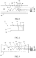
Figure 1 shows a first embodiment of a wear sensor according to the present invention in an operating condition; -
Figure 2 shows a wear sensor according to the present invention in a view from above; -
Figure 3 shows a first embodiment of a wear sensor according to the present invention in a second operating condition; -
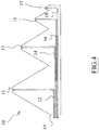
Figure 4 shows another embodiment of a wear sensor according to the present invention; -
Figure 5 shows an axonometric view of the wear sensor according to the present invention before being embedded in a coating whose wear is to be measured; -
Figure 6 shows an axonometric view of a production step of a wear sensor according to the present invention; -
Figure 7 shows a plan view of a vibratory finishing vat to which four sensors are applied according to this invention; and -
Figure 8 shows a plan view of a vibratory finishing vat, showing the connections of the sensors to a control unit. - The invention will now be described with initial reference to
Figure 1 , which illustrates a first embodiment of the present invention, globally indicated bynumerical reference 10. -
Sensor 10 is configured to detect the degree of wear of an object or of apolymer coating 30. - Non-limitative examples of such polymeric objects or coatings may be polymeric coatings for vibratory finishing vats, for load-bearing grids for screening or not for screening.
- Other applications may concern polyurethane coated rollers, for example in the field of coils rollers, in the steel sector, rotating bodies or pump bodies in polyurethane and similar elastomers and coatings of loading hoppers, weighing hoppers, discharge hoppers from mixing groups and any type of vat or silos and other applications.
- As is well known, polymeric materials derive from the polymerisation reaction of a quantity of basic molecules (monomers) to form even very long chains.
- A polymeric material is generally composed of macromolecules consisting of the same type of repetitive unit.
- Examples of polymeric materials include polyurethanes, elastomers such as silicone rubbers and rubbers, and other polymers.
- As shown in
figure 1 ,sensor 10 includes abody 20 made of polymeric material. - The polymeric material of the
body 20 of thesensor 10 may be equal to that of thecoating 30 or article of which wear must be measured, or it may be a polymer having mechanical properties very similar to those of the coating 30 material or article of which wear must be measured. - Preferably, the hardness of the polymer material of which
sensor 10 is composed is equal to or slightly less than the hardness of the polymer material of which to measure wear. - The
body 20 of the sensor is configured to be immersed in the polymer material whose wear is measured and saidbody 20 has a number ofreliefs 21, 22, 23, 24 each one having anapex - In a variant of the invention, the
sensor 10, instead of being immersed in the polymer material whose wear is to be measured, is covered by it. - For each of the
apexes sensor 10 there is aconnection control unit 100, progressively more severe levels of wear when the wear of the polymer material whose wear is measured spreads to therespective apex sensor 10. - The progressively more severe levels of wear are therefore associated with first, second, third level wear signals and so on until the last serious wear alarm level.
- For example in
Figure 1 Level I is associated with a first level wear alarm, Level II is associated with a medium level wear alarm, Level III is associated with an advanced wear alarm and Level IV is associated with a severe wear alarm. Other connection and configurations of alarms are possible. - To manage these different alarm levels, the
control unit 100 can be connected to amemory unit 110 containing its operating software. - To generate such alarm signals,
sensor 10 shall be connected to controlunit 100, with each apex separately connected to controlunit 100, so that the interruption of its connection is such that a corresponding alarm I, II, III and IV is generated. - According to an embodiment of the invention, the connection with the
control unit 100 is an electrical connection between an apex of the sensor body and thecontrol unit 100. - An advantage of this solution is that the cable conducts electricity. The interruption of the passage of electricity determines a change of state (e.g. from 1 to 0) signaling a condition of wear.
- According to one embodiment of the invention, the connection with the control unit is an optical connection made by means of a fiberglass cable between an apex of the sensor body and a control unit.
- An advantage of this solution is that it avoids "polluting" by releasing heavy metals during the wear of the sensor connection. In this case, using a fiberglass cable, which conducts light between an emitter and a receiver of the sensor and the interruption of the passage of light causes a change in state (e.g. 1 to 0), as in the previous case.
- Alternatively, the connection to the
control unit 100 can be a fluid connection between a tip of the sensor body and the control unit. -
Figure 3 , for example, illustrates an operating condition of the sensor where the first connection 12 (corresponding to apex 11) is interrupted, generating a first level wear alarm. -
Figure 4 shows another embodiment of a wear sensor according to the present invention, in which in particular theconnections sensor 10 are oriented towards the highest side of each apex having four sloping heights, while the remaining portions of theconnections body 20 of thesensor 10 and protrude on oneside 19 of thesame body 20. -
Figure 5 shows an axonometric view of the wear sensor according to the present invention before being immersed in a coating whose wear to be measured. -
Figure 6 shows an axonometric view of a production step of the wear sensor. - In this case, the sensor connections, such as electrical cables, are configured inside a mold, before receiving a cast of polymeric material, such as polyurethane that makes the sensor 10 a unique body. In this configuration, the cables face the lower side of the sensor positioning mask in the pouring mold. The presence of a metal or polymeric frame, e.g. made by rapid prototyping, could be envisaged.
-
Figure 7 shows a plan view of avat 50 for vibratory finishing work to which four sensors are applied according to this invention. -
Vat 50 has a metal bottom, said bottom being covered with a covering in polymeric material. - An example of anti-wear coating par excellence, but not limited to the possibilities of the invention, is represented by the various families of polyurethanes, rubbers and silicone rubbers.
-
Vat 50 incorporates at least one wear sensor of the type described above, where thatwear sensor 10 is embedded in or covered by that polymer liner. - In the example shown, the
vat 50 is of the type with trapezoidal section bottom and equipped withcentral body 52. - Preferably in
vat 50, thewear sensors 10 are arranged in a radial configuration in which thelower apex 17 of thebody 20 of thesensor 10 are oriented towards the centre of thevat 50. - The area of the lower sensor is specially oriented towards the center of the vat towards which the vibration tends to wear out more the anti-abrasive coating.
-
Figure 8 shows a plan view of a vibratory finishing vat in which the connections of the sensors to acontrol unit 100 are indicated. - In particular, the
wear sensors 10 are connected each to thecontrol unit 100 by means of aflat cable 55 adherent to the bottom of thevat 50 in a first length and to thecentral body 52 of the vat in a second length and then converge in asingle cable terminal 57 that goes down through the inner side of thecentral body 52 until it connects with a terminal block on the base of thevat 50 for connection to thecontrol unit 100. - Alternatively, the
sensor 10 can also be independent and wireless, in order to communicate with thecontrol unit 100 via Wi-Fi or other known wireless connection, taking advantage of its own autonomy ensured by a battery or a generative kinetic source of current, for example thanks to the vibratory or rotational movement of thevat 50, as for bicycles or car wheels. - Alternatively, the connection between
sensor 10 andcontrol unit 100 can be an inductive RFID (Radio Frequency Identification) connection. - Further applications of the
sensor 10 of the invention may be as follows. - Firstly, the
sensors 10 can be applied to a load-bearing grid for screeing stones or other mechanical selections, where the load-bearing grid is made of or lined with polymeric material, where the load-bearing grid has at least onewear sensor 10 as described, where thewear sensor 10 is embedded in or covered with polymeric material. - Secondly, the
sensors 10 can be applied to rollers coated with polymeric material. - Also in this case, the
wear sensor 10 is immersed or covered by the polymer coating. - In this regard, it should be noted that the continuous monitoring of advanced sensors can determine improved quality factors of the process managed by the roller, if not increased safety factors (for example in the field of coils rollers, in the steel sector). In addition, the
sensors 10 can be applied to pump impellers where the impellers are made of polymeric material. - Once properly monitored, the impeller bodies or, if necessary, the impellers themselves, could generate new scenarios of technological enrichment and offer possible developments in fields where exceptional levels of reliability are required.
- Finally, the sensors can be applied to hoppers made of or lined with polymeric material, or in all those cases where monitoring of the hopper cladding is desirable.
- Obviously, modifications or improvements may be made to the invention as described for contingent or particular reasons, without going beyond the scope of the invention as claimed below.
Claims (12)
- A system comprising an object or a coating (30) made of polymeric material and a sensor (10) for detecting the degree of wear of the object or of the coating (30) made of polymeric material, wherein the sensor (10) comprises a body (20) made of polymeric material, said body (20) being immersed in or covered by the polymeric material of which wear has to be measured, wherein said body (20) has a plurality of reliefs (21,22,23,24) each having an apex (11,13,15,17) placed at a different height, and wherein a connection (12,14,16,18) for each of the apexes (11,13,15,17) is provided, the connection being configured when interrupted to signal to a control unit (100) progressively more severe levels of wear when the wear of the polymeric material of the object or of the coating (30) propagates to the respective apex (11,13,15,17) of the sensor (10).
- A system as in claim 1, wherein said connection (12, 14, 16, 18) is an electrical connection, or an optical connection made by a fiberglass cable, or is a fluid connection, each of said connections being made between an apex of the body (20) of the sensor (10) and the control unit (100).
- A system as in claim 1, wherein said connection (12,14,16,18) between an apex of the body (20) of the sensor (10) and the control unit (100) is an inductive RFID connection or a wireless connection powered by a battery or by a kinetic source for generating electrical current.
- A system as in claim 1, wherein the polymeric material of the body (20) of the sensor (10) is equal to the polymeric material of the coating (30) or of the object of which wear has to be measured, or is a polymeric material having mechanical properties very similar to that of the polymeric material of the coating (30) or of the object of which wear has to be measured.
- A system as in claim 1, wherein the hardness of the polymeric material of which the sensor (10) is made is equal to or is slightly less than the hardness of the polymeric material of the coating (30) or of the object of which wear has to be measured.
- A vat (50) for the containment of media for surface treatment of finishing pieces, wherein said vat (50) comprises a metallic bottom (40), said bottom (40) being coated with a coating (30) of polymeric material, said vat (50) comprising at least one wear sensor (10) as claimed in one or more of the preceding claims, wherein said wear sensor (10) is immersed in or coated with the polymeric coating of the vat (50).
- The vat (50) as in claim 6, wherein the wear sensors (10) are arranged in a radial configuration where the lower apexes (16) of the body (20) of the sensor (10) are oriented towards the center of the vat (50).
- The vat (50) as claimed in claim 6, wherein the wear sensors (10) are each connected to the control unit (100) or by a flat cable (55) adhering to the bottom of the vat (50) for a certain length and to a central body (52) of the vat (50) for another length and then converge into a single terminal cable (57) which passes through the inner side of the central body (52) until it is coupled with a terminal block on the base of the vat (50).
- A load-bearing grid for stone screening or other mechanical selections, where said grid is made of or coated with polymeric material, wherein said grid comprises at least one wear sensor (10) as in claims 1-5, wherein said wear sensor (10) is immersed in or coated with polymeric material.
- A roller coated in polymeric material, said roller comprising at least one wear sensor (10) as claimed in claims 1-5, wherein said wear sensor (10) is immersed in or coated with polymeric material.
- An impeller for pumps wherein said impeller is made of polymeric material, wherein said impeller body comprises at least one wear sensor (10) as in claims 1-5, wherein said wear sensor (10) is immersed in or coated with polymeric material.
- A hopper made of or covered with polymeric material, wherein said hopper comprises at least one wear sensor (10) as claimed in claims 1-5, wherein said wear sensor (10) is immersed in or coated with the polymeric material.
Applications Claiming Priority (1)
| Application Number | Priority Date | Filing Date | Title |
|---|---|---|---|
| IT102017000104763A IT201700104763A1 (en) | 2017-09-19 | 2017-09-19 | WEAR SENSOR |
Publications (2)
| Publication Number | Publication Date |
|---|---|
| EP3457079A1 EP3457079A1 (en) | 2019-03-20 |
| EP3457079B1 true EP3457079B1 (en) | 2020-08-05 |
Family
ID=61148319
Family Applications (1)
| Application Number | Title | Priority Date | Filing Date |
|---|---|---|---|
| EP18192987.8A Active EP3457079B1 (en) | 2017-09-19 | 2018-09-06 | Wear sensor |
Country Status (2)
| Country | Link |
|---|---|
| EP (1) | EP3457079B1 (en) |
| IT (1) | IT201700104763A1 (en) |
Family Cites Families (5)
| Publication number | Priority date | Publication date | Assignee | Title |
|---|---|---|---|---|
| US4655077A (en) * | 1985-05-31 | 1987-04-07 | Purvis Howard A | Wear sensor system |
| JP3227928B2 (en) * | 1993-08-06 | 2001-11-12 | 住友電装株式会社 | Patware indicator |
| CA2557445A1 (en) * | 2004-02-27 | 2005-09-09 | Mcgill University | Method and device for sensing wear |
| US7180409B2 (en) * | 2005-03-11 | 2007-02-20 | Temic Automotive Of North America, Inc. | Tire tread wear sensor system |
| AU2016100152A4 (en) * | 2015-02-13 | 2016-03-24 | Metso Outotec Finland Oy | Wear Sensor |
-
2017
- 2017-09-19 IT IT102017000104763A patent/IT201700104763A1/en unknown
-
2018
- 2018-09-06 EP EP18192987.8A patent/EP3457079B1/en active Active
Non-Patent Citations (1)
| Title |
|---|
| None * |
Also Published As
| Publication number | Publication date |
|---|---|
| EP3457079A1 (en) | 2019-03-20 |
| IT201700104763A1 (en) | 2019-03-19 |
Similar Documents
| Publication | Publication Date | Title |
|---|---|---|
| CN105592927B (en) | Method and device for continuous monitoring of wear in a grinding circuit | |
| FI101350B (en) | Device for recording milling volume present in mill drum | |
| FI94377B (en) | System and device for measuring a grinding machine, tolerance, wear and fit | |
| CA2968638C (en) | Methods and apparatus for the continuous monitoring of wear and pressure in centrifugal concentrators | |
| AU2013251976B2 (en) | Bearing monitoring method and system | |
| KR101108772B1 (en) | Device for regenerating molding sand | |
| US10603674B2 (en) | Impact crusher rotor position detection and control | |
| US20260036132A1 (en) | Centrifugal Pump Having Wear-Resistant Wear Plate With Scraper Element | |
| US20060226984A1 (en) | Wear detection by transponder destruction | |
| EP3770100B1 (en) | Elevator sheave liner | |
| JP6247776B2 (en) | Method and apparatus for controlling the manufacturing process of components of vehicle wheel tires | |
| EP3457079A1 (en) | Wear sensor | |
| CA2243421A1 (en) | Method for bonding dual-phase stainless steel | |
| CA2839360A1 (en) | System and method for monitoring a condition of at least one nozzle | |
| JP2015202933A (en) | Conveyor belt wear measurement device | |
| AU2023204144B2 (en) | A Grinding Disc For A Grinding Machine | |
| KR20170133089A (en) | Automatic weighing and packaging equipment of the short ball | |
| US4292723A (en) | Sheave and method of providing same | |
| CN1154982A (en) | Composite wear-resistant structural material | |
| CN108328354A (en) | The method and device of control feeding amount for bucket wheel reclaimer | |
| EA033718B1 (en) | Method for producing milled elastomer | |
| KR101985269B1 (en) | Silo system with dust removal function and mixing function | |
| CN202329144U (en) | Sintering raw material feeding device | |
| CN213349094U (en) | Ball mill discharging cover and amino molding compound ball mill | |
| CN118355193A (en) | Centrifugal pump with wear-resistant wearing wall with scraper element |
Legal Events
| Date | Code | Title | Description |
|---|---|---|---|
| PUAI | Public reference made under article 153(3) epc to a published international application that has entered the european phase |
Free format text: ORIGINAL CODE: 0009012 |
|
| STAA | Information on the status of an ep patent application or granted ep patent |
Free format text: STATUS: THE APPLICATION HAS BEEN PUBLISHED |
|
| AK | Designated contracting states |
Kind code of ref document: A1 Designated state(s): AL AT BE BG CH CY CZ DE DK EE ES FI FR GB GR HR HU IE IS IT LI LT LU LV MC MK MT NL NO PL PT RO RS SE SI SK SM TR |
|
| AX | Request for extension of the european patent |
Extension state: BA ME |
|
| RIN1 | Information on inventor provided before grant (corrected) |
Inventor name: REDAELLI, PAOLO |
|
| STAA | Information on the status of an ep patent application or granted ep patent |
Free format text: STATUS: REQUEST FOR EXAMINATION WAS MADE |
|
| RBV | Designated contracting states (corrected) |
Designated state(s): AL AT BE BG CH CY CZ DE DK EE ES FI FR GB GR HR HU IE IS IT LI LT LU LV MC MK MT NL NO PL PT RO RS SE SI SK SM TR |
|
| 17P | Request for examination filed |
Effective date: 20190917 |
|
| GRAJ | Information related to disapproval of communication of intention to grant by the applicant or resumption of examination proceedings by the epo deleted |
Free format text: ORIGINAL CODE: EPIDOSDIGR1 |
|
| GRAP | Despatch of communication of intention to grant a patent |
Free format text: ORIGINAL CODE: EPIDOSNIGR1 |
|
| GRAP | Despatch of communication of intention to grant a patent |
Free format text: ORIGINAL CODE: EPIDOSNIGR1 |
|
| STAA | Information on the status of an ep patent application or granted ep patent |
Free format text: STATUS: GRANT OF PATENT IS INTENDED |
|
| RIC1 | Information provided on ipc code assigned before grant |
Ipc: G01N 3/56 20060101ALI20200207BHEP Ipc: G01B 21/08 20060101AFI20200207BHEP |
|
| INTG | Intention to grant announced |
Effective date: 20200228 |
|
| GRAS | Grant fee paid |
Free format text: ORIGINAL CODE: EPIDOSNIGR3 |
|
| GRAA | (expected) grant |
Free format text: ORIGINAL CODE: 0009210 |
|
| STAA | Information on the status of an ep patent application or granted ep patent |
Free format text: STATUS: THE PATENT HAS BEEN GRANTED |
|
| AK | Designated contracting states |
Kind code of ref document: B1 Designated state(s): AL AT BE BG CH CY CZ DE DK EE ES FI FR GB GR HR HU IE IS IT LI LT LU LV MC MK MT NL NO PL PT RO RS SE SI SK SM TR |
|
| REG | Reference to a national code |
Ref country code: GB Ref legal event code: FG4D |
|
| REG | Reference to a national code |
Ref country code: CH Ref legal event code: EP |
|
| REG | Reference to a national code |
Ref country code: AT Ref legal event code: REF Ref document number: 1299325 Country of ref document: AT Kind code of ref document: T Effective date: 20200815 |
|
| REG | Reference to a national code |
Ref country code: DE Ref legal event code: R096 Ref document number: 602018006623 Country of ref document: DE |
|
| REG | Reference to a national code |
Ref country code: IE Ref legal event code: FG4D |
|
| REG | Reference to a national code |
Ref country code: LT Ref legal event code: MG4D |
|
| REG | Reference to a national code |
Ref country code: NL Ref legal event code: MP Effective date: 20200805 |
|
| REG | Reference to a national code |
Ref country code: AT Ref legal event code: MK05 Ref document number: 1299325 Country of ref document: AT Kind code of ref document: T Effective date: 20200805 |
|
| PG25 | Lapsed in a contracting state [announced via postgrant information from national office to epo] |
Ref country code: SE Free format text: LAPSE BECAUSE OF FAILURE TO SUBMIT A TRANSLATION OF THE DESCRIPTION OR TO PAY THE FEE WITHIN THE PRESCRIBED TIME-LIMIT Effective date: 20200805 Ref country code: BG Free format text: LAPSE BECAUSE OF FAILURE TO SUBMIT A TRANSLATION OF THE DESCRIPTION OR TO PAY THE FEE WITHIN THE PRESCRIBED TIME-LIMIT Effective date: 20201105 Ref country code: GR Free format text: LAPSE BECAUSE OF FAILURE TO SUBMIT A TRANSLATION OF THE DESCRIPTION OR TO PAY THE FEE WITHIN THE PRESCRIBED TIME-LIMIT Effective date: 20201106 Ref country code: ES Free format text: LAPSE BECAUSE OF FAILURE TO SUBMIT A TRANSLATION OF THE DESCRIPTION OR TO PAY THE FEE WITHIN THE PRESCRIBED TIME-LIMIT Effective date: 20200805 Ref country code: LT Free format text: LAPSE BECAUSE OF FAILURE TO SUBMIT A TRANSLATION OF THE DESCRIPTION OR TO PAY THE FEE WITHIN THE PRESCRIBED TIME-LIMIT Effective date: 20200805 Ref country code: NO Free format text: LAPSE BECAUSE OF FAILURE TO SUBMIT A TRANSLATION OF THE DESCRIPTION OR TO PAY THE FEE WITHIN THE PRESCRIBED TIME-LIMIT Effective date: 20201105 Ref country code: AT Free format text: LAPSE BECAUSE OF FAILURE TO SUBMIT A TRANSLATION OF THE DESCRIPTION OR TO PAY THE FEE WITHIN THE PRESCRIBED TIME-LIMIT Effective date: 20200805 Ref country code: FI Free format text: LAPSE BECAUSE OF FAILURE TO SUBMIT A TRANSLATION OF THE DESCRIPTION OR TO PAY THE FEE WITHIN THE PRESCRIBED TIME-LIMIT Effective date: 20200805 Ref country code: PT Free format text: LAPSE BECAUSE OF FAILURE TO SUBMIT A TRANSLATION OF THE DESCRIPTION OR TO PAY THE FEE WITHIN THE PRESCRIBED TIME-LIMIT Effective date: 20201207 Ref country code: HR Free format text: LAPSE BECAUSE OF FAILURE TO SUBMIT A TRANSLATION OF THE DESCRIPTION OR TO PAY THE FEE WITHIN THE PRESCRIBED TIME-LIMIT Effective date: 20200805 |
|
| PG25 | Lapsed in a contracting state [announced via postgrant information from national office to epo] |
Ref country code: RS Free format text: LAPSE BECAUSE OF FAILURE TO SUBMIT A TRANSLATION OF THE DESCRIPTION OR TO PAY THE FEE WITHIN THE PRESCRIBED TIME-LIMIT Effective date: 20200805 Ref country code: PL Free format text: LAPSE BECAUSE OF FAILURE TO SUBMIT A TRANSLATION OF THE DESCRIPTION OR TO PAY THE FEE WITHIN THE PRESCRIBED TIME-LIMIT Effective date: 20200805 Ref country code: LV Free format text: LAPSE BECAUSE OF FAILURE TO SUBMIT A TRANSLATION OF THE DESCRIPTION OR TO PAY THE FEE WITHIN THE PRESCRIBED TIME-LIMIT Effective date: 20200805 Ref country code: NL Free format text: LAPSE BECAUSE OF FAILURE TO SUBMIT A TRANSLATION OF THE DESCRIPTION OR TO PAY THE FEE WITHIN THE PRESCRIBED TIME-LIMIT Effective date: 20200805 Ref country code: IS Free format text: LAPSE BECAUSE OF FAILURE TO SUBMIT A TRANSLATION OF THE DESCRIPTION OR TO PAY THE FEE WITHIN THE PRESCRIBED TIME-LIMIT Effective date: 20201205 |
|
| PG25 | Lapsed in a contracting state [announced via postgrant information from national office to epo] |
Ref country code: SM Free format text: LAPSE BECAUSE OF FAILURE TO SUBMIT A TRANSLATION OF THE DESCRIPTION OR TO PAY THE FEE WITHIN THE PRESCRIBED TIME-LIMIT Effective date: 20200805 Ref country code: EE Free format text: LAPSE BECAUSE OF FAILURE TO SUBMIT A TRANSLATION OF THE DESCRIPTION OR TO PAY THE FEE WITHIN THE PRESCRIBED TIME-LIMIT Effective date: 20200805 Ref country code: RO Free format text: LAPSE BECAUSE OF FAILURE TO SUBMIT A TRANSLATION OF THE DESCRIPTION OR TO PAY THE FEE WITHIN THE PRESCRIBED TIME-LIMIT Effective date: 20200805 Ref country code: DK Free format text: LAPSE BECAUSE OF FAILURE TO SUBMIT A TRANSLATION OF THE DESCRIPTION OR TO PAY THE FEE WITHIN THE PRESCRIBED TIME-LIMIT Effective date: 20200805 Ref country code: CZ Free format text: LAPSE BECAUSE OF FAILURE TO SUBMIT A TRANSLATION OF THE DESCRIPTION OR TO PAY THE FEE WITHIN THE PRESCRIBED TIME-LIMIT Effective date: 20200805 |
|
| REG | Reference to a national code |
Ref country code: DE Ref legal event code: R097 Ref document number: 602018006623 Country of ref document: DE |
|
| PG25 | Lapsed in a contracting state [announced via postgrant information from national office to epo] |
Ref country code: MC Free format text: LAPSE BECAUSE OF FAILURE TO SUBMIT A TRANSLATION OF THE DESCRIPTION OR TO PAY THE FEE WITHIN THE PRESCRIBED TIME-LIMIT Effective date: 20200805 Ref country code: AL Free format text: LAPSE BECAUSE OF FAILURE TO SUBMIT A TRANSLATION OF THE DESCRIPTION OR TO PAY THE FEE WITHIN THE PRESCRIBED TIME-LIMIT Effective date: 20200805 |
|
| PLBE | No opposition filed within time limit |
Free format text: ORIGINAL CODE: 0009261 |
|
| STAA | Information on the status of an ep patent application or granted ep patent |
Free format text: STATUS: NO OPPOSITION FILED WITHIN TIME LIMIT |
|
| REG | Reference to a national code |
Ref country code: BE Ref legal event code: MM Effective date: 20200930 |
|
| PG25 | Lapsed in a contracting state [announced via postgrant information from national office to epo] |
Ref country code: LU Free format text: LAPSE BECAUSE OF NON-PAYMENT OF DUE FEES Effective date: 20200906 Ref country code: SK Free format text: LAPSE BECAUSE OF FAILURE TO SUBMIT A TRANSLATION OF THE DESCRIPTION OR TO PAY THE FEE WITHIN THE PRESCRIBED TIME-LIMIT Effective date: 20200805 |
|
| 26N | No opposition filed |
Effective date: 20210507 |
|
| PG25 | Lapsed in a contracting state [announced via postgrant information from national office to epo] |
Ref country code: FR Free format text: LAPSE BECAUSE OF NON-PAYMENT OF DUE FEES Effective date: 20201005 |
|
| PG25 | Lapsed in a contracting state [announced via postgrant information from national office to epo] |
Ref country code: SI Free format text: LAPSE BECAUSE OF FAILURE TO SUBMIT A TRANSLATION OF THE DESCRIPTION OR TO PAY THE FEE WITHIN THE PRESCRIBED TIME-LIMIT Effective date: 20200805 Ref country code: IE Free format text: LAPSE BECAUSE OF NON-PAYMENT OF DUE FEES Effective date: 20200906 Ref country code: BE Free format text: LAPSE BECAUSE OF NON-PAYMENT OF DUE FEES Effective date: 20200930 |
|
| REG | Reference to a national code |
Ref country code: CH Ref legal event code: PL |
|
| PG25 | Lapsed in a contracting state [announced via postgrant information from national office to epo] |
Ref country code: TR Free format text: LAPSE BECAUSE OF FAILURE TO SUBMIT A TRANSLATION OF THE DESCRIPTION OR TO PAY THE FEE WITHIN THE PRESCRIBED TIME-LIMIT Effective date: 20200805 Ref country code: MT Free format text: LAPSE BECAUSE OF FAILURE TO SUBMIT A TRANSLATION OF THE DESCRIPTION OR TO PAY THE FEE WITHIN THE PRESCRIBED TIME-LIMIT Effective date: 20200805 Ref country code: CY Free format text: LAPSE BECAUSE OF FAILURE TO SUBMIT A TRANSLATION OF THE DESCRIPTION OR TO PAY THE FEE WITHIN THE PRESCRIBED TIME-LIMIT Effective date: 20200805 |
|
| PG25 | Lapsed in a contracting state [announced via postgrant information from national office to epo] |
Ref country code: MK Free format text: LAPSE BECAUSE OF FAILURE TO SUBMIT A TRANSLATION OF THE DESCRIPTION OR TO PAY THE FEE WITHIN THE PRESCRIBED TIME-LIMIT Effective date: 20200805 |
|
| PG25 | Lapsed in a contracting state [announced via postgrant information from national office to epo] |
Ref country code: LI Free format text: LAPSE BECAUSE OF NON-PAYMENT OF DUE FEES Effective date: 20210930 Ref country code: CH Free format text: LAPSE BECAUSE OF NON-PAYMENT OF DUE FEES Effective date: 20210930 |
|
| GBPC | Gb: european patent ceased through non-payment of renewal fee |
Effective date: 20220906 |
|
| PG25 | Lapsed in a contracting state [announced via postgrant information from national office to epo] |
Ref country code: GB Free format text: LAPSE BECAUSE OF NON-PAYMENT OF DUE FEES Effective date: 20220906 |
|
| PGFP | Annual fee paid to national office [announced via postgrant information from national office to epo] |
Ref country code: DE Payment date: 20250825 Year of fee payment: 8 |
|
| PGFP | Annual fee paid to national office [announced via postgrant information from national office to epo] |
Ref country code: IT Payment date: 20250904 Year of fee payment: 8 |