EP3457070A1 - Manifold for a heat exchanger assembly and method for manufacturing such a manifold - Google Patents
Manifold for a heat exchanger assembly and method for manufacturing such a manifold Download PDFInfo
- Publication number
- EP3457070A1 EP3457070A1 EP17461606.0A EP17461606A EP3457070A1 EP 3457070 A1 EP3457070 A1 EP 3457070A1 EP 17461606 A EP17461606 A EP 17461606A EP 3457070 A1 EP3457070 A1 EP 3457070A1
- Authority
- EP
- European Patent Office
- Prior art keywords
- cover
- header
- manifold
- internal
- internal plate
- Prior art date
- Legal status (The legal status is an assumption and is not a legal conclusion. Google has not performed a legal analysis and makes no representation as to the accuracy of the status listed.)
- Granted
Links
Images
Classifications
-
- F—MECHANICAL ENGINEERING; LIGHTING; HEATING; WEAPONS; BLASTING
- F28—HEAT EXCHANGE IN GENERAL
- F28F—DETAILS OF HEAT-EXCHANGE AND HEAT-TRANSFER APPARATUS, OF GENERAL APPLICATION
- F28F9/00—Casings; Header boxes; Auxiliary supports for elements; Auxiliary members within casings
- F28F9/02—Header boxes; End plates
- F28F9/0219—Arrangements for sealing end plates into casing or header box; Header box sub-elements
- F28F9/0224—Header boxes formed by sealing end plates into covers
-
- F—MECHANICAL ENGINEERING; LIGHTING; HEATING; WEAPONS; BLASTING
- F28—HEAT EXCHANGE IN GENERAL
- F28F—DETAILS OF HEAT-EXCHANGE AND HEAT-TRANSFER APPARATUS, OF GENERAL APPLICATION
- F28F9/00—Casings; Header boxes; Auxiliary supports for elements; Auxiliary members within casings
- F28F9/02—Header boxes; End plates
- F28F9/0229—Double end plates; Single end plates with hollow spaces
-
- F—MECHANICAL ENGINEERING; LIGHTING; HEATING; WEAPONS; BLASTING
- F28—HEAT EXCHANGE IN GENERAL
- F28F—DETAILS OF HEAT-EXCHANGE AND HEAT-TRANSFER APPARATUS, OF GENERAL APPLICATION
- F28F2275/00—Fastening; Joining
- F28F2275/08—Fastening; Joining by clamping or clipping
-
- F—MECHANICAL ENGINEERING; LIGHTING; HEATING; WEAPONS; BLASTING
- F28—HEAT EXCHANGE IN GENERAL
- F28F—DETAILS OF HEAT-EXCHANGE AND HEAT-TRANSFER APPARATUS, OF GENERAL APPLICATION
- F28F2275/00—Fastening; Joining
- F28F2275/12—Fastening; Joining by methods involving deformation of the elements
Definitions
- the longitudinal channel 231 can also be open to longitudinal faces of the cover 23 or can end in a distance from the longitudinal faces of the cover 23. If the channel 231 opens to both longitudinal faces the manifold 2 can be provided with a plug 24 at each of its ends. The plugs 22 cover and close the ends of the manifold 2, thus ensuring that the manifold 2 is fluid-tight once assembled.
- the header 21 and the internal plate 22 comprise a plurality of slots 211 and 221, respectively.
- the number and the shape of the slots 211, 221 correspond to the number and the shape of the flow ducts 3.
- the flow ducts 3 fit inside the slots 211, 221 and are in fluid communication with the longitudinal channel 231 of the cover 23.
- the cover 23 is provided with a through port 233 that is in fluid communication with the at least one longitudinal channel 231 of the cover 23.
- the manifold 2 operates as the intermediate manifold the cover 23 does not comprise the through port 233.
- the manifold 2 operates as the inlet/outlet manifold the cover 23 is provided with two through ports 233, each being in fluid communication with one longitudinal channel 231.
- the cover 23 can be provided at both its ends 234 with a recess 235 and a protruding edge 236 adjacent to the recess 235.
- the protruding edge 236 of the cover 23 defines a precise bending line for the ends 214 of the side walls 213 of the header 21.
- the recesses 235 receive the ends 214 of the side walls 213.
- the bending angle ⁇ is in fact greater than the required minimum bending value of 90°, preferably greater than or equal to 100°, more preferably greater than or equal to 120°, for stable crimping purpose.
- This way a stable configuration of the manifold 2 during CAB thermal treatment is ensured.
- this ensures that the risk of loosening the connection between the header 21, the internal plate 22 and the cover 23, and thus the risk of creating gaps between them, is significantly reduced.
Landscapes
- Engineering & Computer Science (AREA)
- Physics & Mathematics (AREA)
- Thermal Sciences (AREA)
- Mechanical Engineering (AREA)
- General Engineering & Computer Science (AREA)
- Heat-Exchange Devices With Radiators And Conduit Assemblies (AREA)
Abstract
Description
- The present invention relates to a manifold for a heat exchanger assembly, especially to a high pressure manifold for automotive heat exchanger assemblies, and a method for manufacturing such a manifold.
- A prior art manifold generally comprises a cover and a header applied and bent on the cover. The cover comprises at least one channel defined therein. The header comprises a series of through slots, which receive a series of flow ducts of a heat exchanger and are in fluid communication with the channel of the cover. Cooperating surfaces of the header and the cover as well as an external surface of the header are bent in a direction opposite to a direction in which the flow ducts are inserted into the manifold.
- However, a series of weak points between the header and the cover can be present in the prior art manifold described above. This is caused by the fact that a brazing material is unevenly distributed over the cooperating surfaces what in turn lead to brazing failures and brazing voids in areas critical for structural strength of the manifold, which operates under very high pressures, typically 120-170 bars with burst up to 250 bars.
- Therefore, during the manifold assembly and brazing process special attention must be paid to the way in which the brazing material is spread over the cooperating surfaces of the manifold. Moreover, special measures must be taken to keep all components of the manifold in tight contact with each other during the assembly and brazing process.
- One aim of the present invention is to provide a manifold for a heat exchanger assembly, which eliminates or at least significantly reduces the drawbacks of the prior art solution described above.
- Another aim of the present invention is to provide a manifold for a heat exchanger assembly, which is more durable, easier to manufacture and more cost-effective.
- The above and other aims are achieved by a manifold and a method as defined in the accompanying claims.
- A manifold for a heat exchanger assembly comprises a cover, which in turn comprises at least one channel defined therein. The manifold further comprises a header applied on the cover. The header comprises a plurality of slots. The cover and the header are bent in a direction extending from the cover towards the header. The manifold further comprises an internal plate sandwiched between the cover and the header and comprising a plurality of slots in fluid communication with the slots of the header and the at least one channel of the cover. The internal plate is bent in the direction extending from the cover towards the header .
- In another embodiment of the present invention the cover includes an internal surface, which has a radius Risc prior to assembly of the manifold. The header includes an internal surface, which has a radius Rish prior to assembly of the manifold. The internal plate includes a first surface facing the internal surface of the header and a second surface facing the internal surface of the cover. Prior to assembly of the manifold the first surface of the internal plate has a radius Rip1, the second surface of the internal plate has a radius Rip2 and Rish>Rip1≥Rip2>Risc.
- Further advantageous embodiments of the present invention are defined in dependent claims.
- Another object of the present invention is a method for manufacturing a manifold for a heat exchanger assembly as defined in claims 6 and 7.
- The manifold constructed according to the present invention is more robust compared to the prior art solutions. Additionally, elastic forces generated by tensioning the components of the manifold ensure that they are tightly kept together what in turn means that non-brazed voids/isles are not formed between surfaces to be brazed.
- The invention will be discussed in more detail below, with reference to the annexed drawings, which show nonlimiting embodiments of the invention, wherein:
-
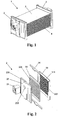
Fig. 1 shows a perspective view of a heat exchanger assembly, -
Fig. 2 shows a perspective exploded view of a manifold used in the heat exchanger assembly offigure 1 , -
Fig. 3 shows an another perspective exploded view of the manifold offigure 2 , -
Fig. 4 shows yet another perspective exploded view of the manifold offigure 2 , -
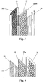
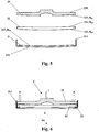
Fig. 5 shows a cross-section exploded view of the manifold, -
Fig. 6 shows a cross-section view of the manifold just before its final assembly, -
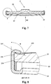
Fig. 7 shows a cross-section view of the manifold, once assembled, -
Fig. 8 shows a detail offigure 7 , -
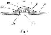
Fig. 9 shows an another embodiment of a cover. - Generally, a
heat exchanger assembly 1 comprises twomanifolds 2 and a plurality of flathollow flow ducts 3. Ends of theflow ducts 3 are received in corresponding slots provided in themanifolds 2. A plurality ofcoolant turbulators 4 can be placed between theflow ducts 3 in such a way that onecoolant turbulator 4 is situated between and in contact with twoadjacent flow ducts 3. In the embodiment shown infigure 1 one of themanifolds 2 is an inlet manifold, while the other is an outlet manifold. - In another embodiments of the invention, one of the
manifolds 2 can operate both as the inlet manifold and the outlet manifold, whereas the other is in fact an intermediate manifold. It means that the intermediate manifold receives a fluid to be cooled down from someflow ducts 3 and guides it back to theother flow ducts 3 so that an U-shaped flow path is created. Theother manifold 2 is configured to both receive a hot fluid from a vehicle and deliver a cool fluid back to the vehicle. Generally, all components of themanifold 2 are brazed to each other. - The
manifold 2 comprises aheader 21, aninternal plate 22 and acover 23. The internal 22 plate is sandwiched between and is in tight contact with theheader 21 and thecover 23. Theinternal plate 22 functions as an interface between theheader 21 and thecover 23. Thecover 23 can define therein at least onelongitudinal channel 231 for a fluid to be cooled down. The number oflongitudinal channels 231 depends on whether themanifold 2 operates as the intermediate manifold (one longitudinal channel) or as the inlet/outlet manifold (two longitudinal channels). The function of thelongitudinal channel 231 is to distribute the fluid to be cooled down along themanifold 2. Thelongitudinal channel 231 is open towards theinternal plate 22. Thelongitudinal channel 231 can also be open to longitudinal faces of thecover 23 or can end in a distance from the longitudinal faces of thecover 23. If thechannel 231 opens to both longitudinal faces themanifold 2 can be provided with aplug 24 at each of its ends. Theplugs 22 cover and close the ends of themanifold 2, thus ensuring that themanifold 2 is fluid-tight once assembled. - The
header 21 and theinternal plate 22 comprise a plurality ofslots slots flow ducts 3. Theflow ducts 3 fit inside theslots longitudinal channel 231 of thecover 23. Thecover 23 is provided with athrough port 233 that is in fluid communication with the at least onelongitudinal channel 231 of thecover 23. However, in another embodiment of the invention, if themanifold 2 operates as the intermediate manifold thecover 23 does not comprise the throughport 233. Moreover, if themanifold 2 operates as the inlet/outlet manifold thecover 23 is provided with two throughports 233, each being in fluid communication with onelongitudinal channel 231. In the latter case, theheat exchanger assembly 1 can be provided with two rows of theflow ducts 3, two rows of theslots 211 and two rows of theslots 221 in bothmanifolds 2, two separatelongitudinal channels 231 in thefirst manifold 2, onelongitudinal channel 231 in thesecond manifold 2 and two throughports 233 in thefirst manifold 2. Thesecond manifold 2 comprises no throughports 233. Themanifold 2 can further comprise aconnection block 25 placed over and in fluid communication with each of the throughports 233 of thecover 23. - The
header 21 is an U-shaped longitudinal element provided with one row of theslots 211. Of course, if more than one row of theflow ducts 3 are used, for example two, theheader 21, as well as theinternal plate 22, is provided with a corresponding number of rows of theslots 211, in this case two. Additionally, the number of thelongitudinal channels 231 of thecover 23 also corresponds to the number of the rows of theflow ducts 3 and theslots longitudinal channel 231 being in fluid communication with one of the rows of theflow ducts 3 and theslots header 21 comprises twoside walls 213, which are longer that the summarized length of theinternal plate 22 and thecover 23 stacked together.Ends 214 of theside walls 213 are bent onends 234 of thecover 23 to assemble all components of themanifold 2 into one unit and keep them together. - The
header 21, theinternal plate 22 and thecover 23 and bent on their cooperating surfaces. Theheader 21 has anexternal surface 216 and aninternal surface 217. Theinternal surface 217 faces theinternal plate 22. Theexternal surface 216 and theinternal surface 217 are both bent towards theflow ducts 3, namely theexternal surface 216 is convex and theinternal surface 217 is concave when viewed in cross-section. Prior to assembly of themanifold 2 theinternal surface 217 has a radius Rish. - The
internal plate 22 has first andsecond surfaces first surface 223 faces theinternal surface 217 of theheader 21. Thesecond surface 224 faces thecover 23. The first andsecond surfaces flow ducts 3, namely thefirst surface 223 is convex and thesecond surface 224 is concave when viewed in cross-section. Prior to assembly of themanifold 2 thefirst surface 223 has a radius Rip1, while thesecond surface 224 has a radius Rip2. - Similarly, the
cover 23 has aninternal surface 237 and anexternal surface 238. Theinternal surface 237 faces thesecond surface 224 of theinternal plate 22. Theinternal surface 237 is bent towards theflow ducts 3, namely theinternal surface 237 is convex when viewed in cross-section. Prior to assembly of themanifold 2 theinternal surface 237 has a radius Risc. - In short, the
header 21, theinternal plate 22 and thecover 23 are bent in a direction D1, which extends from thecover 23 towards theheader 21 and through their centers, when viewed in cross-section. It means that physical points on theexternal surface 216, thefirst surface 223 and theinternal surface 237 located at or near a transverse axis A of themanifold 2 are situated farther away, in respect of the dimension D1, than ends of theheader 21, theinternal plate 22 and thecover 23, respectively. In other words, the direction D1 is opposite to a direction D2, in which theflow ducts 3 are to be inserted into themanifold 2. - Prior to assembly of the
manifold 2, the radii described above meet the following relationship:
- The above relationship can be fulfilled not only by appropriate selection of radius values, but also by appropriate selection of dimensional tolerances of the radii.
- During first steps of the manifold assembly process the relationship referred to above secures physical contact between the
header 21, theinternal plate 22 and thecover 23 in their central area near the transverse axis A of themanifold 2. Then, a pressing force F is exerted on the components of themanifold 2 to bring them together and guarantee complete physical contact between corresponding brazing areas, namely between abrazing area 212 of theheader 2 and afirst brazing area 222a of theinternal plate 22 as well as between asecond brazing area 222b of theinternal plate 22 and abrazing area 232 of thecover 23. To ensure that theheader 21, theinternal plate 22 and thecover 23 are in tight contact during the CAB (Controlled Atmosphere Brazing) brazing process theends 214 of theside walls 213 of theheader 21, as discussed above, are bent at a bending angle α on theends 234 of thecover 23 so that abend 215 is created. The bending angle α is defined as an angle between the extension of thewall 213 of theheader 21 and theend 214 itself after bending. - This particular relationship of the radii, combined with the fact that the ends 214 of the
side walls 213 of theheader 21 are bent on theends 234 of thecover 23, guarantees excellent matching of the mating surfaces of themanifold 2, namely thebrazing areas manifold 2 has been assembled, all cooperating surfaces of themanifold 2 are in tight contact with each other. The shape and surface area of the mating surfaces are configured in such a way that they are sufficient to withstand working conditions of themanifold 2. Moreover, elastic forces arising from the tension of theheader 21, theinternal plate 22 and thecover 23 ensure that all components of themanifold 2 are held as a single unit. - The
cover 23 can be provided at both itsends 234 with arecess 235 and aprotruding edge 236 adjacent to therecess 235. The protrudingedge 236 of thecover 23 defines a precise bending line for theends 214 of theside walls 213 of theheader 21. Therecesses 235 receive theends 214 of theside walls 213. This means that the bending angle α is in fact greater than the required minimum bending value of 90°, preferably greater than or equal to 100°, more preferably greater than or equal to 120°, for stable crimping purpose. This way a stable configuration of themanifold 2 during CAB thermal treatment is ensured. In addition, this ensures that the risk of loosening the connection between theheader 21, theinternal plate 22 and thecover 23, and thus the risk of creating gaps between them, is significantly reduced. - In the embodiments described above it has been indicated that the
internal plate 22 comprises twosurfaces internal plate 22 still has first andsecond surfaces manifold 2 the relationships between all radii take the following forms:


- Taking into account the relationship where Rip1 > Rip2, as discussed earlier, prior to assembly of the
manifold 2 the general relationship between all radii in different embodiments of the invention can be expressed in the following form:
- The
manifold 2 is manufactured in the following way. First, theheader 21, theinternal plate 22 and thecover 23, as described above, are provided. At this stage, generally, the radius relationships defined above apply. Next, theheader 21 is applied on thecover 23 and theinternal plate 22 so that theinternal plate 22 is sandwiched between theheader 21 and thecover 23 and all these three elements are kept together. Also, the pressing force F is exerted on theheader 21, theinternal plate 22 and thecover 23 to bring all these elements to complete tight contact with each other at their corresponding brazing areas. At the end, theends 214 of theheader 21 are bent on theends 234 of thecover 23 and the brazing process takes place. - As described earlier in this description, the
cover 23 can comprise at least onelongitudinal channel 231. Thelongitudinal channel 231 distributes the fluid to be cooled down, especially CO2, along themanifold 2. Thelongitudinal channel 231 can be circular or oval in cross-section. Thelongitudinal channel 231 is arranged in thecover 23 so that the largest dimension LD of thechannel 231 in a direction B between twoends 234 of thecover 23 is contained within the cross-section of thechannel 231. In other words anopen side 231a of thechannel 231 does not include the largest dimension LD of thechannel 231. The width of theopen side 231a in the direction B is smaller than the largest dimension LD of thecover 23 in the same direction. This way aprotrusion 231b is formed at both edges of thelongitudinal channel 231 and theprotrusions 231b are separated by a distance that is smaller than the largest dimension LD of thechannel 231. Furthermore, the stresses arising from mechanical deformations due to the pressure of the fluid to be cooled down concentrate at an area C of thelongitudinal channel 231 and not at theprotrusions 231b. This in turn means that theprojections 231b are subjected to less stress compared to other parts of thelongitudinal channel 231, which in turn makes the connection between theinternal surface 237 of thecover 23 and thesecond surface 224 of theinternal plate 22 more durable, especially in an area near theprojections 231b, and increases the durability of themanifold 2. In addition, by applying this feature, the thickness of thecover 23 can be reduced because thecover 23 itself is more robust. Moreover, this configuration of thecover 23 ensures that thewhole manifold 2 is very durable despite bending and tensioning of its components. - Additionally, a
bulge 239 is formed on theexternal surface 238 of thecover 23. The position of thebulge 239 corresponds to and is a result of the position of thelongitudinal channel 231. As shown in the figures, thebulge 239 can take different shapes and enables easier attachment of theconnection block 25 and/or other elements like hooks, brackets, etc. In fact theconnection block 25 can be integrated in thebulge 239 itself. Moreover, the shape of thebulge 239 can be chosen to match the shape of surrounding components of a vehicle. This feature offers high flexibility in forming thelongitudinal channel 231 and makes it possible to control and minimize an internal volume of thewhole manifold 2. - In the embodiments described above and shown in the figures the through
port 233 for theconnection block 25 is formed on theexternal surface 238 of thecover 23. However, in another embodiment of the present invention, not shown in the figures, the throughport 233 can be defined in theplug 24. In this case, thelongitudinal channel 231 opens to longitudinal faces of thecover 23, which are closed by theplugs 24. One of theplugs 24, or both, comprises at least on throughport 233, which is in fluid communication with thelongitudinal channel 231. This in turn means that the connection block(s) 25 is(are) placed over the throughport 233 in theplug 24 and is(are) connected to theplug 24 itself, either directly or via additional intermediate tubes.
Claims (7)
- A manifold (2) for a heat exchanger assembly (1) comprising:a cover (23), which comprises at least one channel (231) defined therein;a header (21) applied on said cover (23), said header (21) comprising a plurality of slots (211);wherein said cover (23) and said header (21) are bent in a direction (D1) extending from said cover (23) towards said header (21);characterized in thatit further comprises an internal plate (22) sandwiched between said cover (23) and said header (21) and comprising a plurality of slots (221) in fluid communication with said slots (211) of said header (21) and said at least one channel (231) of said cover (23), said internal plate (22) being bent in said direction (D1) extending from said cover (23) towards said header (21).
- The manifold (1) according to claim 1, characterized in that said cover (23) includes an internal surface (237), which has a radius Risc prior to assembly of said manifold (2), said header (21) includes an internal surface (217), which has a radius Rish prior to assembly of said manifold (2), and said internal plate (22) includes a first surface (223) facing said internal surface (217) of said header (21) and a second surface (224) facing said internal surface (237) of said cover (23), wherein prior to assembly of said manifold (2) said first surface (223) of said internal plate (22) has a radius Rip1, said second surface (224) of said internal plate (22) has a radius

- The manifold according to any of claims 1 and 2, characterized in that said cover (23) includes an external surface (238) and two ends (234), said cover (23) being provided on said external surface (238) and at said ends (234) with recesses (235) so that two protruding edges (236) are formed adjacent to said recesses (235), said recesses (235) receiving ends (214) of side walls (213) of said header (21).
- The manifold according to claim 3, characterized in that said ends (214) of said header (21) are bent on said cover (23) at a bending angle (α), which is greater than 90°, preferably greater than 100°, more preferably greater than 120°.
- The manifold according to any of the preceding claims, characterized in that said at least one channel (231) of said cover (23) has the largest dimension (LD), which extends in a direction (B) between said ends (234) of said cover (23) and is included in a cross-section of said at least one channel (231) so that two protrusions (231b) are formed at both edges of said at least one channel (231), said protrusions (231b) are separated by a distance smaller than the largest dimension (LD) of said at least one channel (231).
- A method for manufacturing a manifold (2) for a heat exchanger assembly (1) including the steps of:a: providing a cover (23) comprising at least one channel (231) defined therein, a header (21) having a plurality of slots (211) and an internal plate (22) intended to be sandwiched between said cover (23) and said header (21) and having a plurality of slots (221); said header (21), said internal plate (22) and said cover (23) each being bent in a direction (D1) extending from said cover (23) towards said header (21) ;b: applying said header (21) on said internal plate (22) and said cover (23) so that said header (21), said internal plate (22) and said cover (23) are kept together and said internal plate (22) is sandwiched between said header (21) and said cover (23); andc: brazing said header (21), said internal plate (22) and said cover (23) together.
- The method according to claim 6, wherein said cover (23) includes an internal surface (237), which has a radius Risc prior to step b, said header (21) includes an internal surface (217), which has a radius Rish prior to step b, and said internal plate (22) includes a first surface (223) facing said internal surface (217) of said header (21) and a second surface (224) facing said internal surface (237) of said cover (23), and wherein prior to step b said first surface (223) of said internal plate (22) has a radius Rip1, said second surface (224) of said internal plate (22) has a radius Rip2 and Rish>Rip1≥Rip2>Risc, and wherein step b also includes exerting a force F on said header (21), said internal plate (22) and said cover (23) to bring their corresponding brazing areas into complete contact.
Priority Applications (2)
| Application Number | Priority Date | Filing Date | Title |
|---|---|---|---|
| EP17461606.0A EP3457070B1 (en) | 2017-09-19 | 2017-09-19 | Manifold for a heat exchanger assembly and method for manufacturing such a manifold |
| PCT/EP2018/075303 WO2019057747A1 (en) | 2017-09-19 | 2018-09-19 | Manifold for a heat exchanger assembly and method for manufacturing such a manifold |
Applications Claiming Priority (1)
| Application Number | Priority Date | Filing Date | Title |
|---|---|---|---|
| EP17461606.0A EP3457070B1 (en) | 2017-09-19 | 2017-09-19 | Manifold for a heat exchanger assembly and method for manufacturing such a manifold |
Publications (2)
| Publication Number | Publication Date |
|---|---|
| EP3457070A1 true EP3457070A1 (en) | 2019-03-20 |
| EP3457070B1 EP3457070B1 (en) | 2020-08-19 |
Family
ID=59923372
Family Applications (1)
| Application Number | Title | Priority Date | Filing Date |
|---|---|---|---|
| EP17461606.0A Active EP3457070B1 (en) | 2017-09-19 | 2017-09-19 | Manifold for a heat exchanger assembly and method for manufacturing such a manifold |
Country Status (2)
| Country | Link |
|---|---|
| EP (1) | EP3457070B1 (en) |
| WO (1) | WO2019057747A1 (en) |
Citations (3)
| Publication number | Priority date | Publication date | Assignee | Title |
|---|---|---|---|---|
| WO2005088225A1 (en) * | 2004-03-17 | 2005-09-22 | Showa Denko K.K. | Heat exchanger header tank and heat exchanger comprising same |
| EP2090851A1 (en) * | 2008-02-15 | 2009-08-19 | Delphi Technologies, Inc. | Heat exchanger with a mixing chamber |
| EP2372283A1 (en) * | 2010-03-23 | 2011-10-05 | Delphi Technologies, Inc. | Heat exchanger with a manifold plate |
-
2017
- 2017-09-19 EP EP17461606.0A patent/EP3457070B1/en active Active
-
2018
- 2018-09-19 WO PCT/EP2018/075303 patent/WO2019057747A1/en not_active Ceased
Patent Citations (3)
| Publication number | Priority date | Publication date | Assignee | Title |
|---|---|---|---|---|
| WO2005088225A1 (en) * | 2004-03-17 | 2005-09-22 | Showa Denko K.K. | Heat exchanger header tank and heat exchanger comprising same |
| EP2090851A1 (en) * | 2008-02-15 | 2009-08-19 | Delphi Technologies, Inc. | Heat exchanger with a mixing chamber |
| EP2372283A1 (en) * | 2010-03-23 | 2011-10-05 | Delphi Technologies, Inc. | Heat exchanger with a manifold plate |
Also Published As
| Publication number | Publication date |
|---|---|
| EP3457070B1 (en) | 2020-08-19 |
| WO2019057747A1 (en) | 2019-03-28 |
Similar Documents
| Publication | Publication Date | Title |
|---|---|---|
| US9377252B2 (en) | Heat exchanger and casing for the heat exchanger | |
| US6032728A (en) | Variable pitch heat exchanger | |
| US5329995A (en) | Heat exchanger assembly I | |
| EP2157392A2 (en) | Manifold with multiple passages and crosscounterflow heat exchanger incorporating the same | |
| US7051789B2 (en) | Two-piece mounting bracket for heat exchanger | |
| US5195581A (en) | Snap on radiator tank | |
| US5390733A (en) | Heat exchanger manifold assembly | |
| US20040069475A1 (en) | Heat exchanger | |
| EP2434245B1 (en) | Method of assembly of a heat Exchanger | |
| US6364006B1 (en) | Beaded plate for a heat exchanger and method of making same | |
| EP2151650A2 (en) | Cross-counterflow heat exchanger assembly | |
| EP3610216B1 (en) | A heat exchanger for motor vehicle | |
| JP2008224057A (en) | Heat exchanger, header tank of heat exchanger, and its manufacturing method | |
| EP3567331B1 (en) | Heat exchanger | |
| US20070289727A1 (en) | Heat Exchanger | |
| EP3457070A1 (en) | Manifold for a heat exchanger assembly and method for manufacturing such a manifold | |
| EP3252421B1 (en) | Heat exchanger assembly | |
| CA2635593C (en) | Multi-fluid heat exchanger arrangement | |
| EP2562508A1 (en) | Heat exchanger and method for assembling heat exchanger | |
| US12228354B2 (en) | Adapter for a heat exchanger header | |
| JP4043079B2 (en) | Heat exchanger header pipe | |
| EP3825634B1 (en) | A reinforcement for a heat exchanger | |
| EP0866301A1 (en) | Heat exchanger and method of manufacturing same | |
| US20190353426A1 (en) | Side member and heat exchanger having the same | |
| US20190390917A1 (en) | Heat exchanger header |
Legal Events
| Date | Code | Title | Description |
|---|---|---|---|
| PUAI | Public reference made under article 153(3) epc to a published international application that has entered the european phase |
Free format text: ORIGINAL CODE: 0009012 |
|
| STAA | Information on the status of an ep patent application or granted ep patent |
Free format text: STATUS: THE APPLICATION HAS BEEN PUBLISHED |
|
| AK | Designated contracting states |
Kind code of ref document: A1 Designated state(s): AL AT BE BG CH CY CZ DE DK EE ES FI FR GB GR HR HU IE IS IT LI LT LU LV MC MK MT NL NO PL PT RO RS SE SI SK SM TR |
|
| AX | Request for extension of the european patent |
Extension state: BA ME |
|
| STAA | Information on the status of an ep patent application or granted ep patent |
Free format text: STATUS: REQUEST FOR EXAMINATION WAS MADE |
|
| 17P | Request for examination filed |
Effective date: 20190920 |
|
| RBV | Designated contracting states (corrected) |
Designated state(s): AL AT BE BG CH CY CZ DE DK EE ES FI FR GB GR HR HU IE IS IT LI LT LU LV MC MK MT NL NO PL PT RO RS SE SI SK SM TR |
|
| GRAP | Despatch of communication of intention to grant a patent |
Free format text: ORIGINAL CODE: EPIDOSNIGR1 |
|
| STAA | Information on the status of an ep patent application or granted ep patent |
Free format text: STATUS: GRANT OF PATENT IS INTENDED |
|
| INTG | Intention to grant announced |
Effective date: 20200312 |
|
| GRAS | Grant fee paid |
Free format text: ORIGINAL CODE: EPIDOSNIGR3 |
|
| GRAA | (expected) grant |
Free format text: ORIGINAL CODE: 0009210 |
|
| STAA | Information on the status of an ep patent application or granted ep patent |
Free format text: STATUS: THE PATENT HAS BEEN GRANTED |
|
| AK | Designated contracting states |
Kind code of ref document: B1 Designated state(s): AL AT BE BG CH CY CZ DE DK EE ES FI FR GB GR HR HU IE IS IT LI LT LU LV MC MK MT NL NO PL PT RO RS SE SI SK SM TR |
|
| REG | Reference to a national code |
Ref country code: CH Ref legal event code: EP |
|
| REG | Reference to a national code |
Ref country code: DE Ref legal event code: R096 Ref document number: 602017021892 Country of ref document: DE |
|
| REG | Reference to a national code |
Ref country code: AT Ref legal event code: REF Ref document number: 1304419 Country of ref document: AT Kind code of ref document: T Effective date: 20200915 |
|
| REG | Reference to a national code |
Ref country code: IE Ref legal event code: FG4D |
|
| REG | Reference to a national code |
Ref country code: LT Ref legal event code: MG4D |
|
| REG | Reference to a national code |
Ref country code: NL Ref legal event code: MP Effective date: 20200819 |
|
| PG25 | Lapsed in a contracting state [announced via postgrant information from national office to epo] |
Ref country code: NO Free format text: LAPSE BECAUSE OF FAILURE TO SUBMIT A TRANSLATION OF THE DESCRIPTION OR TO PAY THE FEE WITHIN THE PRESCRIBED TIME-LIMIT Effective date: 20201119 Ref country code: SE Free format text: LAPSE BECAUSE OF FAILURE TO SUBMIT A TRANSLATION OF THE DESCRIPTION OR TO PAY THE FEE WITHIN THE PRESCRIBED TIME-LIMIT Effective date: 20200819 Ref country code: GR Free format text: LAPSE BECAUSE OF FAILURE TO SUBMIT A TRANSLATION OF THE DESCRIPTION OR TO PAY THE FEE WITHIN THE PRESCRIBED TIME-LIMIT Effective date: 20201120 Ref country code: LT Free format text: LAPSE BECAUSE OF FAILURE TO SUBMIT A TRANSLATION OF THE DESCRIPTION OR TO PAY THE FEE WITHIN THE PRESCRIBED TIME-LIMIT Effective date: 20200819 Ref country code: FI Free format text: LAPSE BECAUSE OF FAILURE TO SUBMIT A TRANSLATION OF THE DESCRIPTION OR TO PAY THE FEE WITHIN THE PRESCRIBED TIME-LIMIT Effective date: 20200819 Ref country code: HR Free format text: LAPSE BECAUSE OF FAILURE TO SUBMIT A TRANSLATION OF THE DESCRIPTION OR TO PAY THE FEE WITHIN THE PRESCRIBED TIME-LIMIT Effective date: 20200819 Ref country code: PT Free format text: LAPSE BECAUSE OF FAILURE TO SUBMIT A TRANSLATION OF THE DESCRIPTION OR TO PAY THE FEE WITHIN THE PRESCRIBED TIME-LIMIT Effective date: 20201221 Ref country code: BG Free format text: LAPSE BECAUSE OF FAILURE TO SUBMIT A TRANSLATION OF THE DESCRIPTION OR TO PAY THE FEE WITHIN THE PRESCRIBED TIME-LIMIT Effective date: 20201119 |
|
| REG | Reference to a national code |
Ref country code: AT Ref legal event code: MK05 Ref document number: 1304419 Country of ref document: AT Kind code of ref document: T Effective date: 20200819 |
|
| PG25 | Lapsed in a contracting state [announced via postgrant information from national office to epo] |
Ref country code: NL Free format text: LAPSE BECAUSE OF FAILURE TO SUBMIT A TRANSLATION OF THE DESCRIPTION OR TO PAY THE FEE WITHIN THE PRESCRIBED TIME-LIMIT Effective date: 20200819 Ref country code: PL Free format text: LAPSE BECAUSE OF FAILURE TO SUBMIT A TRANSLATION OF THE DESCRIPTION OR TO PAY THE FEE WITHIN THE PRESCRIBED TIME-LIMIT Effective date: 20200819 Ref country code: RS Free format text: LAPSE BECAUSE OF FAILURE TO SUBMIT A TRANSLATION OF THE DESCRIPTION OR TO PAY THE FEE WITHIN THE PRESCRIBED TIME-LIMIT Effective date: 20200819 Ref country code: LV Free format text: LAPSE BECAUSE OF FAILURE TO SUBMIT A TRANSLATION OF THE DESCRIPTION OR TO PAY THE FEE WITHIN THE PRESCRIBED TIME-LIMIT Effective date: 20200819 Ref country code: IS Free format text: LAPSE BECAUSE OF FAILURE TO SUBMIT A TRANSLATION OF THE DESCRIPTION OR TO PAY THE FEE WITHIN THE PRESCRIBED TIME-LIMIT Effective date: 20201219 |
|
| PG25 | Lapsed in a contracting state [announced via postgrant information from national office to epo] |
Ref country code: SM Free format text: LAPSE BECAUSE OF FAILURE TO SUBMIT A TRANSLATION OF THE DESCRIPTION OR TO PAY THE FEE WITHIN THE PRESCRIBED TIME-LIMIT Effective date: 20200819 Ref country code: EE Free format text: LAPSE BECAUSE OF FAILURE TO SUBMIT A TRANSLATION OF THE DESCRIPTION OR TO PAY THE FEE WITHIN THE PRESCRIBED TIME-LIMIT Effective date: 20200819 Ref country code: RO Free format text: LAPSE BECAUSE OF FAILURE TO SUBMIT A TRANSLATION OF THE DESCRIPTION OR TO PAY THE FEE WITHIN THE PRESCRIBED TIME-LIMIT Effective date: 20200819 Ref country code: DK Free format text: LAPSE BECAUSE OF FAILURE TO SUBMIT A TRANSLATION OF THE DESCRIPTION OR TO PAY THE FEE WITHIN THE PRESCRIBED TIME-LIMIT Effective date: 20200819 Ref country code: CZ Free format text: LAPSE BECAUSE OF FAILURE TO SUBMIT A TRANSLATION OF THE DESCRIPTION OR TO PAY THE FEE WITHIN THE PRESCRIBED TIME-LIMIT Effective date: 20200819 |
|
| REG | Reference to a national code |
Ref country code: CH Ref legal event code: PL |
|
| REG | Reference to a national code |
Ref country code: DE Ref legal event code: R097 Ref document number: 602017021892 Country of ref document: DE |
|
| PG25 | Lapsed in a contracting state [announced via postgrant information from national office to epo] |
Ref country code: AT Free format text: LAPSE BECAUSE OF FAILURE TO SUBMIT A TRANSLATION OF THE DESCRIPTION OR TO PAY THE FEE WITHIN THE PRESCRIBED TIME-LIMIT Effective date: 20200819 Ref country code: AL Free format text: LAPSE BECAUSE OF FAILURE TO SUBMIT A TRANSLATION OF THE DESCRIPTION OR TO PAY THE FEE WITHIN THE PRESCRIBED TIME-LIMIT Effective date: 20200819 Ref country code: ES Free format text: LAPSE BECAUSE OF FAILURE TO SUBMIT A TRANSLATION OF THE DESCRIPTION OR TO PAY THE FEE WITHIN THE PRESCRIBED TIME-LIMIT Effective date: 20200819 Ref country code: MC Free format text: LAPSE BECAUSE OF FAILURE TO SUBMIT A TRANSLATION OF THE DESCRIPTION OR TO PAY THE FEE WITHIN THE PRESCRIBED TIME-LIMIT Effective date: 20200819 |
|
| REG | Reference to a national code |
Ref country code: BE Ref legal event code: MM Effective date: 20200930 |
|
| PLBE | No opposition filed within time limit |
Free format text: ORIGINAL CODE: 0009261 |
|
| STAA | Information on the status of an ep patent application or granted ep patent |
Free format text: STATUS: NO OPPOSITION FILED WITHIN TIME LIMIT |
|
| PG25 | Lapsed in a contracting state [announced via postgrant information from national office to epo] |
Ref country code: SK Free format text: LAPSE BECAUSE OF FAILURE TO SUBMIT A TRANSLATION OF THE DESCRIPTION OR TO PAY THE FEE WITHIN THE PRESCRIBED TIME-LIMIT Effective date: 20200819 Ref country code: LU Free format text: LAPSE BECAUSE OF NON-PAYMENT OF DUE FEES Effective date: 20200919 |
|
| 26N | No opposition filed |
Effective date: 20210520 |
|
| PG25 | Lapsed in a contracting state [announced via postgrant information from national office to epo] |
Ref country code: IT Free format text: LAPSE BECAUSE OF FAILURE TO SUBMIT A TRANSLATION OF THE DESCRIPTION OR TO PAY THE FEE WITHIN THE PRESCRIBED TIME-LIMIT Effective date: 20200819 |
|
| PG25 | Lapsed in a contracting state [announced via postgrant information from national office to epo] |
Ref country code: IE Free format text: LAPSE BECAUSE OF NON-PAYMENT OF DUE FEES Effective date: 20200919 Ref country code: LI Free format text: LAPSE BECAUSE OF NON-PAYMENT OF DUE FEES Effective date: 20200930 Ref country code: SI Free format text: LAPSE BECAUSE OF FAILURE TO SUBMIT A TRANSLATION OF THE DESCRIPTION OR TO PAY THE FEE WITHIN THE PRESCRIBED TIME-LIMIT Effective date: 20200819 Ref country code: CH Free format text: LAPSE BECAUSE OF NON-PAYMENT OF DUE FEES Effective date: 20200930 Ref country code: BE Free format text: LAPSE BECAUSE OF NON-PAYMENT OF DUE FEES Effective date: 20200930 |
|
| GBPC | Gb: european patent ceased through non-payment of renewal fee |
Effective date: 20210919 |
|
| PG25 | Lapsed in a contracting state [announced via postgrant information from national office to epo] |
Ref country code: TR Free format text: LAPSE BECAUSE OF FAILURE TO SUBMIT A TRANSLATION OF THE DESCRIPTION OR TO PAY THE FEE WITHIN THE PRESCRIBED TIME-LIMIT Effective date: 20200819 Ref country code: MT Free format text: LAPSE BECAUSE OF FAILURE TO SUBMIT A TRANSLATION OF THE DESCRIPTION OR TO PAY THE FEE WITHIN THE PRESCRIBED TIME-LIMIT Effective date: 20200819 Ref country code: CY Free format text: LAPSE BECAUSE OF FAILURE TO SUBMIT A TRANSLATION OF THE DESCRIPTION OR TO PAY THE FEE WITHIN THE PRESCRIBED TIME-LIMIT Effective date: 20200819 |
|
| PG25 | Lapsed in a contracting state [announced via postgrant information from national office to epo] |
Ref country code: MK Free format text: LAPSE BECAUSE OF FAILURE TO SUBMIT A TRANSLATION OF THE DESCRIPTION OR TO PAY THE FEE WITHIN THE PRESCRIBED TIME-LIMIT Effective date: 20200819 |
|
| PG25 | Lapsed in a contracting state [announced via postgrant information from national office to epo] |
Ref country code: GB Free format text: LAPSE BECAUSE OF NON-PAYMENT OF DUE FEES Effective date: 20210919 |
|
| P01 | Opt-out of the competence of the unified patent court (upc) registered |
Effective date: 20230528 |
|
| PGFP | Annual fee paid to national office [announced via postgrant information from national office to epo] |
Ref country code: DE Payment date: 20250916 Year of fee payment: 9 |
|
| PGFP | Annual fee paid to national office [announced via postgrant information from national office to epo] |
Ref country code: FR Payment date: 20250929 Year of fee payment: 9 |