EP3457044A1 - Air conditioner - Google Patents
Air conditioner Download PDFInfo
- Publication number
- EP3457044A1 EP3457044A1 EP16901715.9A EP16901715A EP3457044A1 EP 3457044 A1 EP3457044 A1 EP 3457044A1 EP 16901715 A EP16901715 A EP 16901715A EP 3457044 A1 EP3457044 A1 EP 3457044A1
- Authority
- EP
- European Patent Office
- Prior art keywords
- air conditioner
- anomaly
- sensor
- unit
- control
- Prior art date
- Legal status (The legal status is an assumption and is not a legal conclusion. Google has not performed a legal analysis and makes no representation as to the accuracy of the status listed.)
- Granted
Links
Images




Classifications
-
- F—MECHANICAL ENGINEERING; LIGHTING; HEATING; WEAPONS; BLASTING
- F24—HEATING; RANGES; VENTILATING
- F24F—AIR-CONDITIONING; AIR-HUMIDIFICATION; VENTILATION; USE OF AIR CURRENTS FOR SCREENING
- F24F11/00—Control or safety arrangements
- F24F11/89—Arrangement or mounting of control or safety devices
-
- F—MECHANICAL ENGINEERING; LIGHTING; HEATING; WEAPONS; BLASTING
- F24—HEATING; RANGES; VENTILATING
- F24F—AIR-CONDITIONING; AIR-HUMIDIFICATION; VENTILATION; USE OF AIR CURRENTS FOR SCREENING
- F24F11/00—Control or safety arrangements
- F24F11/70—Control systems characterised by their outputs; Constructional details thereof
- F24F11/72—Control systems characterised by their outputs; Constructional details thereof for controlling the supply of treated air, e.g. its pressure
- F24F11/74—Control systems characterised by their outputs; Constructional details thereof for controlling the supply of treated air, e.g. its pressure for controlling air flow rate or air velocity
-
- F—MECHANICAL ENGINEERING; LIGHTING; HEATING; WEAPONS; BLASTING
- F24—HEATING; RANGES; VENTILATING
- F24F—AIR-CONDITIONING; AIR-HUMIDIFICATION; VENTILATION; USE OF AIR CURRENTS FOR SCREENING
- F24F1/00—Room units for air-conditioning, e.g. separate or self-contained units or units receiving primary air from a central station
- F24F1/0003—Room units for air-conditioning, e.g. separate or self-contained units or units receiving primary air from a central station characterised by a split arrangement, wherein parts of the air-conditioning system, e.g. evaporator and condenser, are in separately located units
-
- F—MECHANICAL ENGINEERING; LIGHTING; HEATING; WEAPONS; BLASTING
- F24—HEATING; RANGES; VENTILATING
- F24F—AIR-CONDITIONING; AIR-HUMIDIFICATION; VENTILATION; USE OF AIR CURRENTS FOR SCREENING
- F24F11/00—Control or safety arrangements
- F24F11/30—Control or safety arrangements for purposes related to the operation of the system, e.g. for safety or monitoring
- F24F11/32—Responding to malfunctions or emergencies
- F24F11/36—Responding to malfunctions or emergencies to leakage of heat-exchange fluid
-
- F—MECHANICAL ENGINEERING; LIGHTING; HEATING; WEAPONS; BLASTING
- F24—HEATING; RANGES; VENTILATING
- F24F—AIR-CONDITIONING; AIR-HUMIDIFICATION; VENTILATION; USE OF AIR CURRENTS FOR SCREENING
- F24F11/00—Control or safety arrangements
- F24F11/30—Control or safety arrangements for purposes related to the operation of the system, e.g. for safety or monitoring
- F24F11/32—Responding to malfunctions or emergencies
- F24F11/38—Failure diagnosis
-
- F—MECHANICAL ENGINEERING; LIGHTING; HEATING; WEAPONS; BLASTING
- F24—HEATING; RANGES; VENTILATING
- F24F—AIR-CONDITIONING; AIR-HUMIDIFICATION; VENTILATION; USE OF AIR CURRENTS FOR SCREENING
- F24F11/00—Control or safety arrangements
- F24F11/70—Control systems characterised by their outputs; Constructional details thereof
- F24F11/72—Control systems characterised by their outputs; Constructional details thereof for controlling the supply of treated air, e.g. its pressure
- F24F11/74—Control systems characterised by their outputs; Constructional details thereof for controlling the supply of treated air, e.g. its pressure for controlling air flow rate or air velocity
- F24F11/77—Control systems characterised by their outputs; Constructional details thereof for controlling the supply of treated air, e.g. its pressure for controlling air flow rate or air velocity by controlling the speed of ventilators
-
- Y—GENERAL TAGGING OF NEW TECHNOLOGICAL DEVELOPMENTS; GENERAL TAGGING OF CROSS-SECTIONAL TECHNOLOGIES SPANNING OVER SEVERAL SECTIONS OF THE IPC; TECHNICAL SUBJECTS COVERED BY FORMER USPC CROSS-REFERENCE ART COLLECTIONS [XRACs] AND DIGESTS
- Y02—TECHNOLOGIES OR APPLICATIONS FOR MITIGATION OR ADAPTATION AGAINST CLIMATE CHANGE
- Y02B—CLIMATE CHANGE MITIGATION TECHNOLOGIES RELATED TO BUILDINGS, e.g. HOUSING, HOUSE APPLIANCES OR RELATED END-USER APPLICATIONS
- Y02B30/00—Energy efficient heating, ventilation or air conditioning [HVAC]
- Y02B30/70—Efficient control or regulation technologies, e.g. for control of refrigerant flow, motor or heating
Definitions
- the present invention relates to an air conditioner that detects refrigerant leakage.
- Patent Literature 1 discloses a technology in which an air conditioner includes a refrigerant leakage detection device to warn the user if refrigerant leakage is detected.
- Patent Literature 1 Japanese Patent Application Laid-open No. H7-159010
- the air conditioner described in Patent Literature 1 can detect refrigerant leakage by operating the refrigerant leakage detection device with a storage battery even during transportation and during a non-operation period in which no air conditioning control is performed.
- depletion of the storage battery requires replacement of the storage battery, or otherwise even the normal air conditioning control operation cannot be performed.
- depletion of the storage battery causing the air conditioning control operation to not function may misguide the user to incorrectly think that the air conditioner has failed. This presents a problem of inconvenience to the user.
- the present invention has been made in view of the foregoing, and it is an object of the present invention to provide an air conditioner capable of detecting refrigerant leakage during a non-operation period of air conditioning control without compromising user convenience.
- an air conditioner includes an indoor unit, an outdoor unit, and a remote controller that instructs the indoor unit to control air conditioning.
- the air conditioner includes a first sensor to detect a first anomaly in the indoor unit, the first anomaly being an anomaly relating to leakage of a refrigerant.
- the air conditioner includes a second sensor to detect a second anomaly, the second anomaly being an anomaly other than the first anomaly.
- the air conditioner includes a control unit to activate the first sensor and the second sensor during an operation period in which the air conditioner provides air conditioning control and to activate the first sensor during a non-operation period in which the air conditioner does not provide air conditioning control.
- the air conditioner according to the present invention provides an advantage in that it is possible to detect refrigerant leakage during a non-operation period of air conditioning control without compromising user convenience.
- FIG. 1 is a diagram illustrating an example configuration of an air conditioner 4 according to a first embodiment of the present invention.
- the air conditioner 4 includes an indoor unit 1 and an outdoor unit 2 illustrated in FIG. 1 , and a remote controller (not illustrated in FIG. 1 ) that instructs the indoor unit 1 to control air conditioning.
- the indoor unit 1 is, for example, a tall, floor-mounted indoor unit.
- the outdoor unit 2 is connected to a single indoor unit 1
- the air conditioner 4 may be configured such that the outdoor unit 2 is connected to a plurality of indoor units 1.
- the air conditioner 4 uses a flammable refrigerant (e.g., R32).
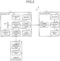
- FIG. 2 is a block diagram illustrating an example configuration of the indoor unit 1, the outdoor unit 2, and a remote controller 3 constituting the air conditioner 4 according to the first embodiment.
- the indoor unit 1 includes a communication unit 11 that communicates with the outdoor unit 2; a control unit 12 that controls the operation of the indoor unit 1; a leak sensor 13 that detects an anomaly relating to leakage of a refrigerant in the indoor unit 1; and a sensor 14 that detects an anomaly other than refrigerant leakage (e.g., an anomaly of the temperature in the indoor unit 1) in the indoor unit 1.
- the leak sensor 13 is, for example, a gas sensor.
- the leak sensor 13 is, for example, a thermistor disposed, in the indoor unit 1, in a pipe through which the refrigerant flows to detect refrigerant leakage by a change in the temperature of the pipe.
- the leak sensor 13 is a first sensor, and the sensor 14 is a second sensor.
- a refrigerant leakage anomaly is a first anomaly, and an anomaly that is not a refrigerant leakage anomaly, i.e., an anomaly other than the first anomaly, is a second anomaly.
- the indoor unit 1 further includes a storage unit 15 that stores control information required, for example, for the control unit 12 to provide air conditioning control; a display unit 16 that displays an anomaly and/or the like detected by the leak sensor 13, the sensor 14, or the like; a communication unit 17 that communicates with the remote controller 3; and a fan 18 that circulates air inside the indoor unit 1.
- a storage unit 15 that stores control information required, for example, for the control unit 12 to provide air conditioning control
- a display unit 16 that displays an anomaly and/or the like detected by the leak sensor 13, the sensor 14, or the like
- a communication unit 17 that communicates with the remote controller 3
- a fan 18 that circulates air inside the indoor unit 1.
- the indoor unit 1 may include a plurality of sensors 14 that each detect a different anomaly.
- the indoor unit 1 may be configured not to include the display unit 16. Note that FIG. 2 only illustrates the components required for an operation of the first embodiment, and omits components that perform a general operation as an indoor unit component.
- the outdoor unit 2 includes a communication unit 21 that communicates with the indoor unit 1; a control unit 22 that controls the operation of the outdoor unit 2; a sensor 23 that detects an anomaly other than refrigerant leakage (e.g., an anomaly of the temperature in the outdoor unit 2) in the outdoor unit 2; and a display unit 24 that displays an anomaly and/or the like detected by the sensor 23.
- the sensor 23 is a second sensor.
- the outdoor unit 2 may include a plurality of sensors 23 that each detect a different anomaly.
- the outdoor unit 2 may be configured not to include the display unit 24. Note that FIG. 2 only illustrates the components required for an operation of the first embodiment, and omits components that perform a general operation as an outdoor unit component.
- the remote controller 3 includes a communication unit 31 that communicates with the indoor unit 1; and a display unit 32 that displays an anomaly and/or the like detected in the indoor unit 1 or in the outdoor unit 2.
- FIG. 2 only illustrates the components required for an operation of the first embodiment, and omits components that perform a general operation as a remote controller component.
- the indoor unit 1 and the remote controller 3 may be configured to be connected to each other by wire or not to be connected to each other by wire. In a case in which the indoor unit 1 and the remote controller 3 are connected to each other by wire, the communication unit 17 of the indoor unit 1 and the communication unit 31 of the remote controller 3 communicate with each other by wired communication. Otherwise, in a case in which the indoor unit 1 and the remote controller 3 are not connected to each other by wire, the communication unit 17 of the indoor unit 1 and the communication unit 31 of the remote controller 3 communicate with each other by wireless communication.
- the indoor unit 1 and the outdoor unit 2 are connected to each other by wire.
- the control unit 12 of the indoor unit 1 exchanges control information and other information with the control unit 22 of the outdoor unit 2 via the communication unit 11 and the communication unit 21 of the outdoor unit 2.
- the control unit 22 of the outdoor unit 2 sends information about an anomaly detected by the sensor 23 to the control unit 12 of the indoor unit 1 via the communication unit 21 and the communication unit 11 of the indoor unit 1.
- the control unit 12 of the indoor unit 1 receives information about an anomaly detected by the sensor 23 of the outdoor unit 2 from the control unit 22 of the outdoor unit 2 via the communication unit 11 and the communication unit 21 of the outdoor unit 2.
- the leak sensor 13, the sensor 14, and the sensor 23 each detect a different anomaly.
- the control unit 12 of the indoor unit 1 activates all the sensors of the air conditioner 4, i.e., the leak sensor 13 and the sensor 14 of the indoor unit 1 and the sensor 23 of the outdoor unit 2, on the basis of the operational state of the air conditioner 4 during an operation period in which the air conditioner 4 provides air conditioning control. Since the control unit 12 is controlling the operation of the indoor unit 1, the control unit 12 can recognize the operational state of the air conditioner 4.
- the control unit 12 activates the leak sensor 13 of the indoor unit 1, but does not activate the sensor 14 of the indoor unit 1 and the sensor 23 of the outdoor unit 2.
- the control unit 12 activates the leak sensor 13 even when the air conditioner 4 is not in operation to enable refrigerant leakage to be detected.
- the control unit 12 supplies the power that is supplied to the control unit 12 to the leak sensor 13 also during a non-operation period.
- This operation enables, in the air conditioner 4, electrical power to be supplied to the leak sensor 13 to cause the leak sensor 13 to operate and to enable refrigerant leakage to be detected even during a non-operation period in which no air conditioning control is performed as long as electrical power is supplied to the indoor unit 1.
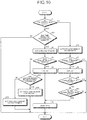
- FIG. 3 is a flowchart illustrating a process of detecting an anomaly that occurs in the air conditioner 4, in the air conditioner 4 according to the first embodiment.
- the control unit 12 of the indoor unit 1 checks whether the air conditioner 4 is not providing air conditioning control, i.e., the air conditioner 4 is in a non-operational state (step S1). If the air conditioner 4 is in a non-operational state (step S1: Yes), the control unit 12 activates the leak sensor 13 (step S2). The control unit 12 checks whether refrigerant leakage has been detected by the leak sensor 13 (step S3). If refrigerant leakage has been detected by the leak sensor 13 (step S3: Yes), the control unit 12 provides control to display information informing that refrigerant leakage has been detected, in any or all of the display unit 16 of the indoor unit 1, the display unit 24 of the outdoor unit 2, and the display unit 32 of the remote controller 3 (step S4). To prevent accumulation of the refrigerant leaked in the indoor unit 1, the control unit 12 provides control to rotate (i.e., start) the fan 18 of the indoor unit 1 (step S5) and then terminates the process.
- the control unit 12 provides control to rotate (i.e.,
- step S3 if there is no refrigerant leakage detected by the leak sensor 13 (step S3: No), the control unit 12 terminates the process.
- step S1 if the air conditioner 4 is providing air conditioning control (step S1: No), the control unit 12 activates the leak sensor 13, the sensor 14, and the sensor 23 (step S6).
- the control unit 12 checks whether an anomaly has been detected by the leak sensor 13, the sensor 14, or the sensor 23 (step S7). If an anomaly has been detected by the leak sensor 13, the sensor 14, or the sensor 23 (step S7: Yes), the control unit 12 provides control to display details of the anomaly based on the sensor that has detected the anomaly, in any or all of the display unit 16 of the indoor unit 1, the display unit 24 of the outdoor unit 2, and the display unit 32 of the remote controller 3 (step S8).
- step S9 If the anomaly detected is refrigerant leakage detected by the leak sensor 13 (step S9: Yes) and the fan 18 of the indoor unit 1 is not in operation (step S10: Yes), then to prevent accumulation of the refrigerant leaked in the indoor unit 1, the control unit 12 provides control to rotate (i.e., start) the fan 18 of the indoor unit 1 (step S5) and then terminates the process.
- step S7 If there is no anomaly detected by the leak sensor 13, the sensor 14, or the sensor 23 (step S7: No), the control unit 12 terminates the process. Alternatively, if the anomaly detected is not refrigerant leakage detected by the leak sensor 13 (step S9: No), the control unit 12 terminates the process. Still alternatively, if the fan 18 of the indoor unit 1 is in operation (step S10: No), the control unit 12 terminates the process.
- the control unit 12 constantly or periodically repeats the process of detecting an anomaly that may occur in the air conditioner 4 as illustrated in FIG. 3 .
- the control unit 12 of the indoor unit 1 may stop supplying electrical power to the leak sensor 13 to inactivate the leak sensor 13.
- the hardware configuration of the indoor unit 1 will next be described.
- the communication unit 11 and the communication unit 17 are implemented in an interface circuit capable of sending and receiving communication data.
- the leak sensor 13 and the sensor 14 are each implemented by a measurement device.
- the storage unit 15 is implemented by a memory.
- the display unit 16 is implemented by a light emitting diode (LED), a monitor, or the like.
- the fan 18 is implemented by a rotational fan unit and a drive unit such as a motor.
- the control unit 12 is implemented in a processing circuit. That is, the indoor unit 1 includes a processing circuit for activating the leak sensor 13, the sensor 14, and the sensor 23 depending on the operational state of the air conditioner 4.
- the processing circuit may be a combination of a central processing unit (CPU) that executes a program stored in a memory and the memory or may be a dedicated hardware element.
- CPU central processing unit
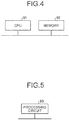
- FIG. 4 is a diagram illustrating an example in which the treatment circuit of the indoor unit 1 according to the first embodiment is configured from a CPU 91 and a memory 92.
- the processing circuit is configured from the CPU 91 and the memory 92
- each function of the control unit 12 is implemented in software, firmware, or a combination of software and firmware.
- the software or firmware is described as a program or programs, and is stored in the memory 92.
- the CPU 91 reads and executes a program or programs stored in the memory 92 to provide the functions of the control unit 12.
- the indoor unit 1 includes the memory 92 for storing the program(s) that, upon execution by the processing circuit, cause(s) the control unit 12 to perform steps of activating the leak sensor 13, the sensor 14, and the sensor 23 depending on the operational state of the air conditioner 4.
- These programs may be described as causing the computer to execute the procedure and method performed by the indoor unit 1.
- the CPU 91 may also be a processing device, a computing unit, a microprocessor, a microcomputer, a processor, a digital signal processor (DSP), or the like.
- Examples of the memory 92 include non-volatile or volatile semiconductor memories such as a random access memory (RAM), a read-only memory (ROM), a flash memory, an erasable programmable ROM (EPROM), and an electrically erasable programmable ROM (EEPROM); a magnetic disk, a flexible disk, an optical disk, a compact disc, a MiniDisc, and a digital versatile disc (DVD).
- RAM random access memory
- ROM read-only memory
- EPROM erasable programmable ROM
- EEPROM electrically erasable programmable ROM
- the memory 92 may be the same memory as the memory for implementing the storage unit 15.
- FIG. 5 is a diagram illustrating an example in which the treatment circuit of the indoor unit 1 according to the first embodiment is configured from a dedicated hardware element.
- a processing circuit 93 illustrated in FIG. 5 is, for example, a single circuit, a set of multiple circuits, a programmed processor, a parallel programmed processor, an application specific integrated circuit (ASIC), a field programmable gate array (FPGA), or a combination thereof.
- the functions of the control unit 12 may be implemented in the processing circuit 93 on a per-function basis or may be implemented collectively in the processing circuit 93.
- control unit 12 may be implemented partially in a dedicated hardware element, and partially in software or firmware. In this manner, the processing circuit can provide the functions described above in dedicated hardware, software, firmware, or a combination thereof.
- the control unit 12 of the indoor unit 1 does not activate the sensors 14 and 23, but supplies electrical power to the leak sensor 13 for activation, during a non-operation period in which the air conditioner 4 does not provide air conditioning control.
- This operation enables the air conditioner 4 to detect refrigerant leakage even during a non-operation period.
- the control unit 12 supplies electrical power to the leak sensor 13 to activate the leak sensor 13 without using a storage battery during a non-operation period of the air conditioner 4, thereby enabling leakage detection to be performed without imposing a burden on the user and thus enabling user convenience to be improved.
- the air conditioner 4 can detect refrigerant leakage during a non-operation period of the air conditioner 4.
- the control unit 12 also provides control not to activate the sensors 14 and 23, other than the leak sensor 13, during a non-operation period of the air conditioner 4. This operation enables the air conditioner 4 to reduce power consumption during a non-operation period as compared to when all the sensors are activated.
- the air conditioner 4 is herein described as detecting continuously only refrigerant leakage during a non-operation period, the configuration is not limited thereto.
- the air conditioner 4 checks the connection status between the indoor unit 1 and the outdoor unit 2 by periodic communication therebetween.
- the air conditioner 4 may also detect a communication anomaly between the indoor unit 1 and the outdoor unit 2 during a non-operation period.
- anomalies that it is anticipated will occur in the air conditioner 4 i.e., anomalies that will be detected by the leak sensor 13 and the sensor 14 of the indoor unit 1 and the sensor 23 of the outdoor unit 2, may each be assigned a severity, and the severity of each of the anomalies may previously be stored in the air conditioner 4.
- the severity information may previously be set and stored in the storage unit 15 by the manufacturer of the air conditioner 4 during the initial configuration stage, and the setting or the initial configuration may be configurable by the user of the air conditioner 4.
- the air conditioner 4 may be configured to activate the first sensor for detecting the first anomaly, which is a high severity anomaly having a severity higher than a predetermined severity, both during an operation period and during a non-operation period, and to activate the second sensor for detecting the second anomaly having a severity lower than the predetermined severity and lower than the severity of the first anomaly only during an operation period.
- the sensor 13 is the first sensor and the sensors 14 and 23 are each the second sensor.
- the air conditioner 4 can promptly detect an anomaly having a large effect on the user by activation of the sensor capable of detecting a high severity anomaly also during a non-operation period to detect a high severity anomaly having a large effect on the user upon occurrence regardless of whether the air conditioning control is being performed or not.
- control unit 12 activates the leak sensor 13 continuously or intermittently during a non-operation period in which the air conditioner 4 does not provide air conditioning control, i.e., when the air conditioner 4 is in a non-operational state. Differences from the first embodiment will be described below.
- FIG. 6 is a diagram illustrating transition of the failure rate of a typical electrical appliance or the like.
- An electrical appliance or the like generally exhibits a tendency to have a higher failure rate during an initial failure period due to reasons such as a manufacturing problem attributable to assemble work, a component problem attributable to a part being used, or an installation problem attributable to installation work in the case of equipment installed in a building such as the air conditioner 4.
- an electrical appliance or the like degrades through continued use, and therefore exhibits a tendency to have a higher failure rate due to the life of the product itself during the aging period.
- there is a quality stabilized period in which the failure rate is low and the product quality is stable if an occurrence of an unexpected problem is not taken into consideration.
- the control unit 12 of the indoor unit 1 activates the leak sensor 13 continuously even when the air conditioner 4 is not in operation.
- the control unit 12 of the indoor unit 1 activates the leak sensor 13 intermittently when the air conditioner 4 is not in operation.
- the control unit 12 activates the leak sensor 13 with a certain period, for example, at predetermined time intervals.
- the control unit 12 stops supplying electrical power to the leak sensor 13 during a time period in which the leak sensor 13 is not activated.
- FIG. 7 is a diagram illustrating a conceptual outline of the amount of power supplied to the leak sensor 13 from the control unit 12 in the second embodiment.
- the control unit 12 supplies electrical power to the leak sensor 13 with a predetermined period, i.e., at predetermined time intervals, to activate the leak sensor 13, and supplies no electrical power to the leak sensor 13 in the other periods not to activate the leak sensor 13. This operation enables the air conditioner 4 to reduce the power usage during a non-operation period of the air conditioner 4 as compared to the first embodiment.
- the control unit 12 of the indoor unit 1 activates the leak sensor 13 continuously when the air conditioner 4 is not in operation.
- Information about the initial failure period, the quality stabilized period, and the aging period illustrated in FIG. 6 and about the cyclic period of electrical power supplied to the leak sensor 13 illustrated in FIG. 7 is stored in the storage unit 15 of the indoor unit 1 as control information.
- the control unit 12 provides control to activate the leak sensor 13 continuously or intermittently as described above on the basis of the control information stored in the storage unit 15.
- FIG. 8 is a flowchart illustrating a process of detecting an anomaly that occurs in the air conditioner 4, in the air conditioner 4 according to the second embodiment. If the air conditioner 4 is in a non-operational state (step S1: Yes), the control unit 12 of the indoor unit 1 checks whether the air conditioner 4 is in a time period to activate the leak sensor 13 (step S21).
- the control unit 12 refers to the control information stored in the storage unit 15, more specifically, information about the initial failure period, the quality stabilized period, and the aging period illustrated in FIG. 6 , and information about the cyclic period of electrical power supplied to the leak sensor 13 illustrated in FIG. 7 .
- the control unit 12 determines that the air conditioner 4 is in a time period to activate the leak sensor 13; and in a time period in which no electrical power is supplied to the leak sensor 13 as illustrated in FIG. 7 in the quality stabilized period, the control unit 12 determines that the air conditioner 4 is in a time period not to activate the leak sensor 13.
- the control unit 12 activates the leak sensor 13 (step S2). Otherwise, in a time period not to activate the leak sensor 13 (step S21: No), the control unit 12 terminates the process.
- the control unit 12 of the indoor unit 1 activates the leak sensor 13 continuously or intermittently depending on the elapsed time from the start of an operation of the air conditioner 4 on the basis of the control information during a non-operation period in which the air conditioner 4 does not provide air conditioning control.
- This operation enables the control unit 12 to activate the leak sensor 13 intermittently during a time period in which refrigerant leakage is less likely to be detected and to activate the leak sensor 13 continuously during a time period in which refrigerant leakage is more likely to be detected, thereby enabling power usage to be reduced during a non-operation period of the air conditioner 4 as compared to the first embodiment.
- control unit 12 activates the leak sensor 13 continuously or intermittently using a different control operation from that of the second embodiment during a non-operation period in which the air conditioner 4 does not provide air conditioning control, i.e., when the air conditioner 4 is in a non-operational state. Differences from the first and second embodiments will be described below.
- FIG. 9 is a diagram illustrating a conceptual outline of transition of the result of measurement of a refrigerant leakage amount, obtained by the leak sensor 13 of the indoor unit 1 in the third embodiment.
- the leak sensor 13 measures the refrigerant leakage amount upon detection of the refrigerant leakage.
- FIG. 9 illustrates a second threshold.
- the second threshold is used such that the control unit 12 determines that refrigerant leaks when the refrigerant leakage amount measured by the leak sensor 13 exceeds the second threshold.
- FIG. 9 also illustrates a first threshold.
- the first threshold is lower than the second threshold and is used in control such that the control unit 12 switches the operational method of the leak sensor 13 when the refrigerant leakage amount measured by the leak sensor 13 exceeds the first threshold.
- the control unit 12 makes the next measurement of the refrigerant leakage amount after a certain interval, i.e., intermittently.
- the time interval for intermittent operation may be the same as the time interval of the second embodiment.
- the control unit 12 makes the next measurement of the refrigerant leakage amount without any interval, i.e., continuously.
- control unit 12 may thereafter make the next measurement of the refrigerant leakage amount again after a certain interval, i.e., intermittently.
- Information about the first threshold and the second threshold illustrated in FIG. 9 i.e., information about the time periods in which the air conditioner 4 activates the leak sensor 13 during a non-operation period, is stored in the storage unit 15 of the indoor unit 1 as control information.
- the control unit 12 provides control to activate the leak sensor 13 continuously or intermittently as described above on the basis of the control information stored in the storage unit 15.
- FIG. 10 is a flowchart illustrating a process of detecting an anomaly that occurs in the air conditioner 4, in the air conditioner 4 according to the third embodiment. If there is no refrigerant leakage detected by the leak sensor 13 (step S3: No), the control unit 12 checks whether the refrigerant leakage amount measured by the leak sensor 13 has exceeded the first threshold (step S31).
- step S31 If the refrigerant leakage amount measured by the leak sensor 13 has exceeded the first threshold (step S31: Yes), the control unit 12 activates the leak sensor 13 continuously (step S32). That is, the control unit 12 makes the next measurement of the refrigerant leakage amount without any interval, i.e., continuously.
- step S31 If the refrigerant leakage amount measured by the leak sensor 13 is at or below the first threshold (step S31: No), the control unit 12 activates the leak sensor 13 intermittently (step S33). That is, the control unit 12 makes the next measurement of the refrigerant leakage amount after a certain interval, i.e., intermittently.
- the control unit 12 of the indoor unit 1 activates the leak sensor 13 continuously or intermittently depending on the refrigerant leakage amount of the previous measurement by the leak sensor 13 on the basis of the control information during a non-operation period in which the air conditioner 4 does not provide air conditioning control.
- This operation enables the control unit 12 to activate the leak sensor 13 intermittently during a time period in which refrigerant leakage is less likely to be detected and to activate the leak sensor 13 continuously during a time period in which refrigerant leakage is more likely to be detected, thereby enabling power usage to be reduced during a non-operation period of the air conditioner 4 similarly to the second embodiment.
Landscapes
- Engineering & Computer Science (AREA)
- Chemical & Material Sciences (AREA)
- Combustion & Propulsion (AREA)
- Mechanical Engineering (AREA)
- General Engineering & Computer Science (AREA)
- Physics & Mathematics (AREA)
- Fluid Mechanics (AREA)
- Health & Medical Sciences (AREA)
- Biomedical Technology (AREA)
- Air Conditioning Control Device (AREA)
Abstract
Description
- The present invention relates to an air conditioner that detects refrigerant leakage.
- To address environmental issues causing ozone depletion, refrigerant used in air conditioners has been changed from conventional fluorocarbons to R32 or the like. Unlike fluorocarbons, R32 is a flammable refrigerant. Leakage of R32 from an air conditioner may cause different problems from the problems that occur when a fluorocarbon leaks.
Patent Literature 1 discloses a technology in which an air conditioner includes a refrigerant leakage detection device to warn the user if refrigerant leakage is detected. - Patent Literature 1: Japanese Patent Application Laid-open No.
H7-159010 - The air conditioner described in
Patent Literature 1 can detect refrigerant leakage by operating the refrigerant leakage detection device with a storage battery even during transportation and during a non-operation period in which no air conditioning control is performed. However, depletion of the storage battery requires replacement of the storage battery, or otherwise even the normal air conditioning control operation cannot be performed. Thus, depletion of the storage battery causing the air conditioning control operation to not function may misguide the user to incorrectly think that the air conditioner has failed. This presents a problem of inconvenience to the user. - The present invention has been made in view of the foregoing, and it is an object of the present invention to provide an air conditioner capable of detecting refrigerant leakage during a non-operation period of air conditioning control without compromising user convenience.
- To solve the problem and achieve the object described above, an air conditioner according to an aspect of the present invention includes an indoor unit, an outdoor unit, and a remote controller that instructs the indoor unit to control air conditioning. The air conditioner includes a first sensor to detect a first anomaly in the indoor unit, the first anomaly being an anomaly relating to leakage of a refrigerant. Moreover, the air conditioner includes a second sensor to detect a second anomaly, the second anomaly being an anomaly other than the first anomaly. Moreover, the air conditioner includes a control unit to activate the first sensor and the second sensor during an operation period in which the air conditioner provides air conditioning control and to activate the first sensor during a non-operation period in which the air conditioner does not provide air conditioning control.
- The air conditioner according to the present invention provides an advantage in that it is possible to detect refrigerant leakage during a non-operation period of air conditioning control without compromising user convenience.
-
-
FIG. 1 is a diagram illustrating an example configuration of an air conditioner according to a first embodiment. -
FIG. 2 is a block diagram illustrating an example configuration of an indoor unit, an outdoor unit, and a remote controller constituting the air conditioner according to the first embodiment. -
FIG. 3 is a flowchart illustrating a process of detecting an anomaly that occurs in the air conditioner, in the air conditioner according to the first embodiment. -
FIG. 4 is a diagram illustrating an example in which a processing circuit of the indoor unit according to the first embodiment is configured from a central processing unit (CPU) and a memory. -
FIG. 5 is a diagram illustrating an example in which a processing circuit of the indoor unit according to the first embodiment is configured from a dedicated hardware element. -
FIG. 6 is a diagram illustrating transition of the failure rate of a typical electrical appliance or the like. -
FIG. 7 is a diagram illustrating a conceptual outline of the amount of power supplied to a leak sensor from a control unit in a second embodiment. -
FIG. 8 is a flowchart illustrating a process of detecting an anomaly that occurs in the air conditioner, in the air conditioner according to the second embodiment. -
FIG. 9 is a diagram illustrating a conceptual outline of transition of the result of measurement of a refrigerant leakage amount, obtained by the leak sensor of the indoor unit in a third embodiment. -
FIG. 10 is a flowchart illustrating a process of detecting an anomaly that occurs in the air conditioner, in the air conditioner according to the third embodiment. - The air conditioner according to embodiments of the present invention will be described in detail below with reference to the drawings. These embodiments are not intended to limit the scope of this invention.
-
FIG. 1 is a diagram illustrating an example configuration of anair conditioner 4 according to a first embodiment of the present invention. Theair conditioner 4 includes anindoor unit 1 and anoutdoor unit 2 illustrated inFIG. 1 , and a remote controller (not illustrated inFIG. 1 ) that instructs theindoor unit 1 to control air conditioning. Theindoor unit 1 is, for example, a tall, floor-mounted indoor unit. Although it is assumed herein that theoutdoor unit 2 is connected to a singleindoor unit 1, theair conditioner 4 may be configured such that theoutdoor unit 2 is connected to a plurality ofindoor units 1. It is also assumed herein that theair conditioner 4 uses a flammable refrigerant (e.g., R32). -
FIG. 2 is a block diagram illustrating an example configuration of theindoor unit 1, theoutdoor unit 2, and aremote controller 3 constituting theair conditioner 4 according to the first embodiment. - The
indoor unit 1 includes acommunication unit 11 that communicates with theoutdoor unit 2; acontrol unit 12 that controls the operation of theindoor unit 1; aleak sensor 13 that detects an anomaly relating to leakage of a refrigerant in theindoor unit 1; and a sensor 14 that detects an anomaly other than refrigerant leakage (e.g., an anomaly of the temperature in the indoor unit 1) in theindoor unit 1. Theleak sensor 13 is, for example, a gas sensor. Alternatively, theleak sensor 13 is, for example, a thermistor disposed, in theindoor unit 1, in a pipe through which the refrigerant flows to detect refrigerant leakage by a change in the temperature of the pipe. Theleak sensor 13 is a first sensor, and the sensor 14 is a second sensor. In addition, a refrigerant leakage anomaly is a first anomaly, and an anomaly that is not a refrigerant leakage anomaly, i.e., an anomaly other than the first anomaly, is a second anomaly. - The
indoor unit 1 further includes astorage unit 15 that stores control information required, for example, for thecontrol unit 12 to provide air conditioning control; adisplay unit 16 that displays an anomaly and/or the like detected by theleak sensor 13, the sensor 14, or the like; acommunication unit 17 that communicates with theremote controller 3; and afan 18 that circulates air inside theindoor unit 1. - The
indoor unit 1 may include a plurality of sensors 14 that each detect a different anomaly. Theindoor unit 1 may be configured not to include thedisplay unit 16. Note thatFIG. 2 only illustrates the components required for an operation of the first embodiment, and omits components that perform a general operation as an indoor unit component. - The
outdoor unit 2 includes acommunication unit 21 that communicates with theindoor unit 1; acontrol unit 22 that controls the operation of theoutdoor unit 2; asensor 23 that detects an anomaly other than refrigerant leakage (e.g., an anomaly of the temperature in the outdoor unit 2) in theoutdoor unit 2; and a display unit 24 that displays an anomaly and/or the like detected by thesensor 23. Thesensor 23 is a second sensor. - The
outdoor unit 2 may include a plurality ofsensors 23 that each detect a different anomaly. Theoutdoor unit 2 may be configured not to include the display unit 24. Note thatFIG. 2 only illustrates the components required for an operation of the first embodiment, and omits components that perform a general operation as an outdoor unit component. - The
remote controller 3 includes acommunication unit 31 that communicates with theindoor unit 1; and a display unit 32 that displays an anomaly and/or the like detected in theindoor unit 1 or in theoutdoor unit 2. - Note that
FIG. 2 only illustrates the components required for an operation of the first embodiment, and omits components that perform a general operation as a remote controller component. - The
indoor unit 1 and theremote controller 3 may be configured to be connected to each other by wire or not to be connected to each other by wire. In a case in which theindoor unit 1 and theremote controller 3 are connected to each other by wire, thecommunication unit 17 of theindoor unit 1 and thecommunication unit 31 of theremote controller 3 communicate with each other by wired communication. Otherwise, in a case in which theindoor unit 1 and theremote controller 3 are not connected to each other by wire, thecommunication unit 17 of theindoor unit 1 and thecommunication unit 31 of theremote controller 3 communicate with each other by wireless communication. - The
indoor unit 1 and theoutdoor unit 2 are connected to each other by wire. Thecontrol unit 12 of theindoor unit 1 exchanges control information and other information with thecontrol unit 22 of theoutdoor unit 2 via thecommunication unit 11 and thecommunication unit 21 of theoutdoor unit 2. Thecontrol unit 22 of theoutdoor unit 2 sends information about an anomaly detected by thesensor 23 to thecontrol unit 12 of theindoor unit 1 via thecommunication unit 21 and thecommunication unit 11 of theindoor unit 1. Thecontrol unit 12 of theindoor unit 1 receives information about an anomaly detected by thesensor 23 of theoutdoor unit 2 from thecontrol unit 22 of theoutdoor unit 2 via thecommunication unit 11 and thecommunication unit 21 of theoutdoor unit 2. Theleak sensor 13, the sensor 14, and thesensor 23 each detect a different anomaly. - In the first embodiment, the
control unit 12 of theindoor unit 1 activates all the sensors of theair conditioner 4, i.e., theleak sensor 13 and the sensor 14 of theindoor unit 1 and thesensor 23 of theoutdoor unit 2, on the basis of the operational state of theair conditioner 4 during an operation period in which theair conditioner 4 provides air conditioning control. Since thecontrol unit 12 is controlling the operation of theindoor unit 1, thecontrol unit 12 can recognize the operational state of theair conditioner 4. - Meanwhile, during a non-operation period in which the
air conditioner 4 does not provide air conditioning control, i.e., when theair conditioner 4 is in a non-operational state, thecontrol unit 12 activates theleak sensor 13 of theindoor unit 1, but does not activate the sensor 14 of theindoor unit 1 and thesensor 23 of theoutdoor unit 2. In view of an effect on the user in a case of flammable refrigerant leakage, thecontrol unit 12 activates theleak sensor 13 even when theair conditioner 4 is not in operation to enable refrigerant leakage to be detected. Thecontrol unit 12 supplies the power that is supplied to thecontrol unit 12 to theleak sensor 13 also during a non-operation period. This operation enables, in theair conditioner 4, electrical power to be supplied to theleak sensor 13 to cause theleak sensor 13 to operate and to enable refrigerant leakage to be detected even during a non-operation period in which no air conditioning control is performed as long as electrical power is supplied to theindoor unit 1. -
FIG. 3 is a flowchart illustrating a process of detecting an anomaly that occurs in theair conditioner 4, in theair conditioner 4 according to the first embodiment. - First, the
control unit 12 of theindoor unit 1 checks whether theair conditioner 4 is not providing air conditioning control, i.e., theair conditioner 4 is in a non-operational state (step S1). If theair conditioner 4 is in a non-operational state (step S1: Yes), thecontrol unit 12 activates the leak sensor 13 (step S2). Thecontrol unit 12 checks whether refrigerant leakage has been detected by the leak sensor 13 (step S3). If refrigerant leakage has been detected by the leak sensor 13 (step S3: Yes), thecontrol unit 12 provides control to display information informing that refrigerant leakage has been detected, in any or all of thedisplay unit 16 of theindoor unit 1, the display unit 24 of theoutdoor unit 2, and the display unit 32 of the remote controller 3 (step S4). To prevent accumulation of the refrigerant leaked in theindoor unit 1, thecontrol unit 12 provides control to rotate (i.e., start) thefan 18 of the indoor unit 1 (step S5) and then terminates the process. - Returning to step S3, if there is no refrigerant leakage detected by the leak sensor 13 (step S3: No), the
control unit 12 terminates the process. - Returning to step S1, if the
air conditioner 4 is providing air conditioning control (step S1: No), thecontrol unit 12 activates theleak sensor 13, the sensor 14, and the sensor 23 (step S6). Thecontrol unit 12 checks whether an anomaly has been detected by theleak sensor 13, the sensor 14, or the sensor 23 (step S7). If an anomaly has been detected by theleak sensor 13, the sensor 14, or the sensor 23 (step S7: Yes), thecontrol unit 12 provides control to display details of the anomaly based on the sensor that has detected the anomaly, in any or all of thedisplay unit 16 of theindoor unit 1, the display unit 24 of theoutdoor unit 2, and the display unit 32 of the remote controller 3 (step S8). If the anomaly detected is refrigerant leakage detected by the leak sensor 13 (step S9: Yes) and thefan 18 of theindoor unit 1 is not in operation (step S10: Yes), then to prevent accumulation of the refrigerant leaked in theindoor unit 1, thecontrol unit 12 provides control to rotate (i.e., start) thefan 18 of the indoor unit 1 (step S5) and then terminates the process. - If there is no anomaly detected by the
leak sensor 13, the sensor 14, or the sensor 23 (step S7: No), thecontrol unit 12 terminates the process. Alternatively, if the anomaly detected is not refrigerant leakage detected by the leak sensor 13 (step S9: No), thecontrol unit 12 terminates the process. Still alternatively, if thefan 18 of theindoor unit 1 is in operation (step S10: No), thecontrol unit 12 terminates the process. - The
control unit 12 constantly or periodically repeats the process of detecting an anomaly that may occur in theair conditioner 4 as illustrated inFIG. 3 . - Note that if the
fan 18 is in operation, the refrigerant leaked in theindoor unit 1 will not accumulate in theindoor unit 1 even if the refrigerant leaks in theindoor unit 1. Accordingly, if thefan 18 of theindoor unit 1 is in operation, thecontrol unit 12 of theindoor unit 1 may stop supplying electrical power to theleak sensor 13 to inactivate theleak sensor 13. - The hardware configuration of the
indoor unit 1 will next be described. In theindoor unit 1, thecommunication unit 11 and thecommunication unit 17 are implemented in an interface circuit capable of sending and receiving communication data. Theleak sensor 13 and the sensor 14 are each implemented by a measurement device. Thestorage unit 15 is implemented by a memory. Thedisplay unit 16 is implemented by a light emitting diode (LED), a monitor, or the like. Thefan 18 is implemented by a rotational fan unit and a drive unit such as a motor. Thecontrol unit 12 is implemented in a processing circuit. That is, theindoor unit 1 includes a processing circuit for activating theleak sensor 13, the sensor 14, and thesensor 23 depending on the operational state of theair conditioner 4. The processing circuit may be a combination of a central processing unit (CPU) that executes a program stored in a memory and the memory or may be a dedicated hardware element. -
FIG. 4 is a diagram illustrating an example in which the treatment circuit of theindoor unit 1 according to the first embodiment is configured from aCPU 91 and amemory 92. In a case in which the processing circuit is configured from theCPU 91 and thememory 92, each function of thecontrol unit 12 is implemented in software, firmware, or a combination of software and firmware. The software or firmware is described as a program or programs, and is stored in thememory 92. In the processing circuit, theCPU 91 reads and executes a program or programs stored in thememory 92 to provide the functions of thecontrol unit 12. That is, theindoor unit 1 includes thememory 92 for storing the program(s) that, upon execution by the processing circuit, cause(s) thecontrol unit 12 to perform steps of activating theleak sensor 13, the sensor 14, and thesensor 23 depending on the operational state of theair conditioner 4. These programs may be described as causing the computer to execute the procedure and method performed by theindoor unit 1. TheCPU 91 may also be a processing device, a computing unit, a microprocessor, a microcomputer, a processor, a digital signal processor (DSP), or the like. Examples of thememory 92 include non-volatile or volatile semiconductor memories such as a random access memory (RAM), a read-only memory (ROM), a flash memory, an erasable programmable ROM (EPROM), and an electrically erasable programmable ROM (EEPROM); a magnetic disk, a flexible disk, an optical disk, a compact disc, a MiniDisc, and a digital versatile disc (DVD). Thememory 92 may be the same memory as the memory for implementing thestorage unit 15. -
FIG. 5 is a diagram illustrating an example in which the treatment circuit of theindoor unit 1 according to the first embodiment is configured from a dedicated hardware element. In a case in which the processing circuit is a dedicated hardware element, aprocessing circuit 93 illustrated inFIG. 5 is, for example, a single circuit, a set of multiple circuits, a programmed processor, a parallel programmed processor, an application specific integrated circuit (ASIC), a field programmable gate array (FPGA), or a combination thereof. The functions of thecontrol unit 12 may be implemented in theprocessing circuit 93 on a per-function basis or may be implemented collectively in theprocessing circuit 93. - The functions of the
control unit 12 may be implemented partially in a dedicated hardware element, and partially in software or firmware. In this manner, the processing circuit can provide the functions described above in dedicated hardware, software, firmware, or a combination thereof. - As described above, according to the present embodiment, the
control unit 12 of theindoor unit 1 does not activate thesensors 14 and 23, but supplies electrical power to theleak sensor 13 for activation, during a non-operation period in which theair conditioner 4 does not provide air conditioning control. This operation enables theair conditioner 4 to detect refrigerant leakage even during a non-operation period. In addition, thecontrol unit 12 supplies electrical power to theleak sensor 13 to activate theleak sensor 13 without using a storage battery during a non-operation period of theair conditioner 4, thereby enabling leakage detection to be performed without imposing a burden on the user and thus enabling user convenience to be improved. As long as theindoor unit 1 is plugged into a receptacle in a usual house, theair conditioner 4 can detect refrigerant leakage during a non-operation period of theair conditioner 4. Thecontrol unit 12 also provides control not to activate thesensors 14 and 23, other than theleak sensor 13, during a non-operation period of theair conditioner 4. This operation enables theair conditioner 4 to reduce power consumption during a non-operation period as compared to when all the sensors are activated. - Although the
air conditioner 4 is herein described as detecting continuously only refrigerant leakage during a non-operation period, the configuration is not limited thereto. In general, theair conditioner 4 checks the connection status between theindoor unit 1 and theoutdoor unit 2 by periodic communication therebetween. Thus, theair conditioner 4 may also detect a communication anomaly between theindoor unit 1 and theoutdoor unit 2 during a non-operation period. - Moreover, anomalies that it is anticipated will occur in the
air conditioner 4, i.e., anomalies that will be detected by theleak sensor 13 and the sensor 14 of theindoor unit 1 and thesensor 23 of theoutdoor unit 2, may each be assigned a severity, and the severity of each of the anomalies may previously be stored in theair conditioner 4. The severity information may previously be set and stored in thestorage unit 15 by the manufacturer of theair conditioner 4 during the initial configuration stage, and the setting or the initial configuration may be configurable by the user of theair conditioner 4. Theair conditioner 4 may be configured to activate the first sensor for detecting the first anomaly, which is a high severity anomaly having a severity higher than a predetermined severity, both during an operation period and during a non-operation period, and to activate the second sensor for detecting the second anomaly having a severity lower than the predetermined severity and lower than the severity of the first anomaly only during an operation period. For example, in theair conditioner 4, thesensor 13 is the first sensor and thesensors 14 and 23 are each the second sensor. Theair conditioner 4 can promptly detect an anomaly having a large effect on the user by activation of the sensor capable of detecting a high severity anomaly also during a non-operation period to detect a high severity anomaly having a large effect on the user upon occurrence regardless of whether the air conditioning control is being performed or not. - In a second embodiment, the
control unit 12 activates theleak sensor 13 continuously or intermittently during a non-operation period in which theair conditioner 4 does not provide air conditioning control, i.e., when theair conditioner 4 is in a non-operational state. Differences from the first embodiment will be described below. - The configurations of the
indoor unit 1, theoutdoor unit 2, and theremote controller 3 are similar to those of the first embodiment.FIG. 6 is a diagram illustrating transition of the failure rate of a typical electrical appliance or the like. An electrical appliance or the like generally exhibits a tendency to have a higher failure rate during an initial failure period due to reasons such as a manufacturing problem attributable to assemble work, a component problem attributable to a part being used, or an installation problem attributable to installation work in the case of equipment installed in a building such as theair conditioner 4. Moreover, an electrical appliance or the like degrades through continued use, and therefore exhibits a tendency to have a higher failure rate due to the life of the product itself during the aging period. In contrast, between the initial failure period and the aging period, there is a quality stabilized period in which the failure rate is low and the product quality is stable if an occurrence of an unexpected problem is not taken into consideration. - In the initial failure period after installation (i.e., start of an operation) of the
air conditioner 4, taking into consideration a characteristic of the failure rate of a typical electrical appliance illustrated inFIG. 6 , thecontrol unit 12 of theindoor unit 1 activates theleak sensor 13 continuously even when theair conditioner 4 is not in operation. - In the quality stabilized period after the initial failure period has elapsed from the start of an operation of the
air conditioner 4 and before the aging period, thecontrol unit 12 of theindoor unit 1 activates theleak sensor 13 intermittently when theair conditioner 4 is not in operation. Thecontrol unit 12 activates theleak sensor 13 with a certain period, for example, at predetermined time intervals. Thecontrol unit 12 stops supplying electrical power to theleak sensor 13 during a time period in which theleak sensor 13 is not activated.FIG. 7 is a diagram illustrating a conceptual outline of the amount of power supplied to theleak sensor 13 from thecontrol unit 12 in the second embodiment. Thecontrol unit 12 supplies electrical power to theleak sensor 13 with a predetermined period, i.e., at predetermined time intervals, to activate theleak sensor 13, and supplies no electrical power to theleak sensor 13 in the other periods not to activate theleak sensor 13. This operation enables theair conditioner 4 to reduce the power usage during a non-operation period of theair conditioner 4 as compared to the first embodiment. - Then, when the time period after the start of an operation of the
air conditioner 4 enters the aging period, thecontrol unit 12 of theindoor unit 1 activates theleak sensor 13 continuously when theair conditioner 4 is not in operation. - Information about the initial failure period, the quality stabilized period, and the aging period illustrated in
FIG. 6 and about the cyclic period of electrical power supplied to theleak sensor 13 illustrated inFIG. 7 , i.e., information about the time periods in which theair conditioner 4 activates theleak sensor 13 during a non-operation period, is stored in thestorage unit 15 of theindoor unit 1 as control information. Thecontrol unit 12 provides control to activate theleak sensor 13 continuously or intermittently as described above on the basis of the control information stored in thestorage unit 15. -
FIG. 8 is a flowchart illustrating a process of detecting an anomaly that occurs in theair conditioner 4, in theair conditioner 4 according to the second embodiment. If theair conditioner 4 is in a non-operational state (step S1: Yes), thecontrol unit 12 of theindoor unit 1 checks whether theair conditioner 4 is in a time period to activate the leak sensor 13 (step S21). - The
control unit 12 refers to the control information stored in thestorage unit 15, more specifically, information about the initial failure period, the quality stabilized period, and the aging period illustrated inFIG. 6 , and information about the cyclic period of electrical power supplied to theleak sensor 13 illustrated inFIG. 7 . In the initial failure period, in the aging period, and in a time period in which electrical power is supplied to theleak sensor 13 as illustrated inFIG. 7 in the quality stabilized period, thecontrol unit 12 determines that theair conditioner 4 is in a time period to activate theleak sensor 13; and in a time period in which no electrical power is supplied to theleak sensor 13 as illustrated inFIG. 7 in the quality stabilized period, thecontrol unit 12 determines that theair conditioner 4 is in a time period not to activate theleak sensor 13. In a time period to activate the leak sensor 13 (step S21: Yes), thecontrol unit 12 activates the leak sensor 13 (step S2). Otherwise, in a time period not to activate the leak sensor 13 (step S21: No), thecontrol unit 12 terminates the process. - The other part of the process illustrated in
FIG. 8 is similar to the process of the flowchart ofFIG. 3 illustrated in relation to the first embodiment. - As described above, according to the present embodiment, the
control unit 12 of theindoor unit 1 activates theleak sensor 13 continuously or intermittently depending on the elapsed time from the start of an operation of theair conditioner 4 on the basis of the control information during a non-operation period in which theair conditioner 4 does not provide air conditioning control. This operation enables thecontrol unit 12 to activate theleak sensor 13 intermittently during a time period in which refrigerant leakage is less likely to be detected and to activate theleak sensor 13 continuously during a time period in which refrigerant leakage is more likely to be detected, thereby enabling power usage to be reduced during a non-operation period of theair conditioner 4 as compared to the first embodiment. - In a third embodiment, the
control unit 12 activates theleak sensor 13 continuously or intermittently using a different control operation from that of the second embodiment during a non-operation period in which theair conditioner 4 does not provide air conditioning control, i.e., when theair conditioner 4 is in a non-operational state. Differences from the first and second embodiments will be described below. - The configurations of the
indoor unit 1, theoutdoor unit 2, and theremote controller 3 are similar to those of the first embodiment.FIG. 9 is a diagram illustrating a conceptual outline of transition of the result of measurement of a refrigerant leakage amount, obtained by theleak sensor 13 of theindoor unit 1 in the third embodiment. Theleak sensor 13 measures the refrigerant leakage amount upon detection of the refrigerant leakage. -
FIG. 9 illustrates a second threshold. The second threshold is used such that thecontrol unit 12 determines that refrigerant leaks when the refrigerant leakage amount measured by theleak sensor 13 exceeds the second threshold. -
FIG. 9 also illustrates a first threshold. The first threshold is lower than the second threshold and is used in control such that thecontrol unit 12 switches the operational method of theleak sensor 13 when the refrigerant leakage amount measured by theleak sensor 13 exceeds the first threshold. - If the refrigerant leakage amount measured by the
leak sensor 13 is at or below the first threshold, it is unlikely that the refrigerant leakage amount will exceed the second threshold within a short time period. Thus, thecontrol unit 12 makes the next measurement of the refrigerant leakage amount after a certain interval, i.e., intermittently. The time interval for intermittent operation may be the same as the time interval of the second embodiment. - In contrast, if the refrigerant leakage amount detected by the
leak sensor 13 exceeds the first threshold, the refrigerant leakage amount may thereafter exceed the second threshold. Thus, thecontrol unit 12 makes the next measurement of the refrigerant leakage amount without any interval, i.e., continuously. - Even after the refrigerant leakage amount has exceeded the first threshold and the
control unit 12 has continuously measured the refrigerant leakage amount, if the refrigerant leakage amount falls below the first threshold, then thecontrol unit 12 may thereafter make the next measurement of the refrigerant leakage amount again after a certain interval, i.e., intermittently. - Information about the first threshold and the second threshold illustrated in
FIG. 9 , i.e., information about the time periods in which theair conditioner 4 activates theleak sensor 13 during a non-operation period, is stored in thestorage unit 15 of theindoor unit 1 as control information. Thecontrol unit 12 provides control to activate theleak sensor 13 continuously or intermittently as described above on the basis of the control information stored in thestorage unit 15. -
FIG. 10 is a flowchart illustrating a process of detecting an anomaly that occurs in theair conditioner 4, in theair conditioner 4 according to the third embodiment. If there is no refrigerant leakage detected by the leak sensor 13 (step S3: No), thecontrol unit 12 checks whether the refrigerant leakage amount measured by theleak sensor 13 has exceeded the first threshold (step S31). - If the refrigerant leakage amount measured by the
leak sensor 13 has exceeded the first threshold (step S31: Yes), thecontrol unit 12 activates theleak sensor 13 continuously (step S32). That is, thecontrol unit 12 makes the next measurement of the refrigerant leakage amount without any interval, i.e., continuously. - If the refrigerant leakage amount measured by the
leak sensor 13 is at or below the first threshold (step S31: No), thecontrol unit 12 activates theleak sensor 13 intermittently (step S33). That is, thecontrol unit 12 makes the next measurement of the refrigerant leakage amount after a certain interval, i.e., intermittently. - The other part of the process illustrated in
FIG. 10 is similar to the process of the flowchart ofFIG. 8 illustrated in relation to the second embodiment. - As described above, according to the present embodiment, the
control unit 12 of theindoor unit 1 activates theleak sensor 13 continuously or intermittently depending on the refrigerant leakage amount of the previous measurement by theleak sensor 13 on the basis of the control information during a non-operation period in which theair conditioner 4 does not provide air conditioning control. This operation enables thecontrol unit 12 to activate theleak sensor 13 intermittently during a time period in which refrigerant leakage is less likely to be detected and to activate theleak sensor 13 continuously during a time period in which refrigerant leakage is more likely to be detected, thereby enabling power usage to be reduced during a non-operation period of theair conditioner 4 similarly to the second embodiment. - The configurations described in the foregoing embodiments are merely examples of various aspects of the present invention. These configurations may be combined with a known other technology, and moreover, a part of such configurations may be omitted and/or modified without departing from the spirit of the present invention.
- 1 indoor unit; 2 outdoor unit; 3 remote controller; 4 air conditioner; 11, 17, 21, 31 communication unit; 12, 22 control unit; 13 leak sensor; 14, 23 sensor; 15 storage unit; 16, 24, 32 display unit; 18 fan.
Claims (8)
- An air conditioner including an indoor unit, an outdoor unit, and a remote controller that instructs the indoor unit to control air conditioning, the air conditioner comprising:a first sensor to detect a first anomaly in the indoor unit, the first anomaly being an anomaly relating to leakage of a refrigerant;a second sensor to detect a second anomaly, the second anomaly being an anomaly other than the first anomaly; anda control unit to activate the first sensor and the second sensor during an operation period in which the air conditioner provides air conditioning control and to activate the first sensor during a non-operation period in which the air conditioner does not provide air conditioning control.
- The air conditioner according to claim 1, wherein the control unit causes the first anomaly or the second anomaly to be displayed on a display unit included in the indoor unit, in the outdoor unit, or in the remote controller.
- The air conditioner according to claim 1 or 2, wherein if the first anomaly is detected, the control unit provides control to activate a fan included in the indoor unit if the fan is not in operation.
- The air conditioner according to any one of claims 1 to 3 comprising:a storage unit to store control information including information for a time period in which the air conditioner activates the first sensor during a non-operation period, wherein,if the air conditioner is not in operation, the control unit refers to the control information and activates the first sensor continuously or intermittently.
- The air conditioner according to claim 4, wherein the control unit activates the first sensor continuously or intermittently depending on an elapsed time from a start of an operation of the air conditioner.
- The air conditioner according to claim 4, wherein the control unit activates the first sensor continuously or intermittently depending on a refrigerant leakage amount of a previous measurement by the first sensor.
- The air conditioner according to any one of claims 1 to 6, wherein the first sensor is a gas sensor or a thermistor disposed in a pipe through which the refrigerant flows to detect leakage of the refrigerant on a basis of a change in temperature of the pipe.
- An air conditioner including an indoor unit, an outdoor unit, and a remote controller that instructs the indoor unit to control air conditioning, the air conditioner, if each anomaly occurring in the air conditioner is assigned a severity, comprising:a first sensor to detect a first anomaly, the first anomaly being a high severity anomaly having a severity higher than a predetermined severity;a second sensor to detect a second anomaly having a severity lower than the predetermined severity and lower than the severity of the first anomaly; anda control unit to activate the first sensor and the second sensor during an operation period in which the air conditioner provides air conditioning control and to activate the first sensor during a non-operation period in which the air conditioner does not provide air conditioning control.
Applications Claiming Priority (1)
| Application Number | Priority Date | Filing Date | Title |
|---|---|---|---|
| PCT/JP2016/064374 WO2017195367A1 (en) | 2016-05-13 | 2016-05-13 | Air conditioner |
Publications (3)
| Publication Number | Publication Date |
|---|---|
| EP3457044A1 true EP3457044A1 (en) | 2019-03-20 |
| EP3457044A4 EP3457044A4 (en) | 2019-05-15 |
| EP3457044B1 EP3457044B1 (en) | 2024-10-02 |
Family
ID=60266437
Family Applications (1)
| Application Number | Title | Priority Date | Filing Date |
|---|---|---|---|
| EP16901715.9A Active EP3457044B1 (en) | 2016-05-13 | 2016-05-13 | Air conditioner |
Country Status (4)
| Country | Link |
|---|---|
| EP (1) | EP3457044B1 (en) |
| JP (1) | JP6537714B2 (en) |
| CN (1) | CN109073262B (en) |
| WO (1) | WO2017195367A1 (en) |
Cited By (5)
| Publication number | Priority date | Publication date | Assignee | Title |
|---|---|---|---|---|
| FR3102237A1 (en) * | 2019-10-16 | 2021-04-23 | Systemair AC | Flammable gas evacuation device inside an air conditioner or heat pump |
| WO2022072174A1 (en) | 2020-09-29 | 2022-04-07 | Emerson Climate Technologies, Inc. | Refrigerant leak sensor power control systems and methods |
| US11971183B2 (en) | 2019-09-05 | 2024-04-30 | Trane International Inc. | Systems and methods for refrigerant leak detection in a climate control system |
| US12117191B2 (en) | 2022-06-24 | 2024-10-15 | Trane International Inc. | Climate control system with improved leak detector |
| US12487008B2 (en) | 2022-01-14 | 2025-12-02 | Trane International Inc. | Method of commissioning an HVAC system |
Families Citing this family (7)
| Publication number | Priority date | Publication date | Assignee | Title |
|---|---|---|---|---|
| CN113272594B (en) * | 2019-01-22 | 2022-11-22 | 三菱电机株式会社 | Air conditioner |
| EP3875861B1 (en) * | 2020-03-06 | 2023-05-17 | Daikin Industries, Ltd. | Air-conditioner, air-conditioning system, and method for monitoring air-conditioner |
| JP7598014B2 (en) * | 2021-03-10 | 2024-12-11 | ダイキン工業株式会社 | Refrigeration System |
| JP7197814B2 (en) * | 2021-05-21 | 2022-12-28 | ダイキン工業株式会社 | Refrigerant leak detection system |
| JP7713638B2 (en) * | 2021-08-23 | 2025-07-28 | パナソニックIpマネジメント株式会社 | Air Conditioning Equipment |
| JP7713639B2 (en) * | 2021-08-23 | 2025-07-28 | パナソニックIpマネジメント株式会社 | Air Conditioning Equipment |
| CN115507499B (en) * | 2022-09-29 | 2025-01-24 | 青岛海信日立空调系统有限公司 | Refrigeration equipment and refrigerant status detection device |
Family Cites Families (18)
| Publication number | Priority date | Publication date | Assignee | Title |
|---|---|---|---|---|
| JPH06180166A (en) * | 1992-12-09 | 1994-06-28 | Toshiba Corp | Air-conditioner |
| JP3414464B2 (en) | 1993-12-09 | 2003-06-09 | 松下電器産業株式会社 | Air conditioner |
| JP3387592B2 (en) * | 1993-12-21 | 2003-03-17 | 株式会社オーケーエム | Fluid leak detection system |
| JP3521337B2 (en) * | 1995-01-09 | 2004-04-19 | 三菱電機株式会社 | Control device for air conditioner |
| JP3291407B2 (en) * | 1995-01-31 | 2002-06-10 | 三洋電機株式会社 | Cooling device |
| JPH10307050A (en) * | 1997-05-08 | 1998-11-17 | Tokyo Gas Co Ltd | Gas meter |
| JP2000249434A (en) * | 1999-02-24 | 2000-09-14 | Daikin Ind Ltd | Refrigeration equipment |
| JP3720215B2 (en) * | 1999-06-11 | 2005-11-24 | 株式会社コロナ | Air conditioner control device |
| JP5436625B2 (en) * | 2012-06-22 | 2014-03-05 | 三菱電機株式会社 | Refrigerant leakage determination apparatus, refrigeration apparatus, and refrigerant leakage determination method |
| CN105308395B (en) * | 2013-06-18 | 2018-01-23 | 三菱电机株式会社 | freezer |
| JP6379372B2 (en) * | 2013-07-10 | 2018-08-29 | 理研計器株式会社 | Gas detection system |
| KR102150441B1 (en) * | 2013-07-26 | 2020-09-01 | 엘지전자 주식회사 | Air conditioner |
| JP5761306B2 (en) * | 2013-11-06 | 2015-08-12 | ダイキン工業株式会社 | Refrigeration unit heat source unit |
| JP2015094526A (en) * | 2013-11-12 | 2015-05-18 | ダイキン工業株式会社 | Indoor unit |
| JP2015117931A (en) * | 2013-11-14 | 2015-06-25 | ダイキン工業株式会社 | Indoor unit |
| JP5865529B1 (en) * | 2014-07-15 | 2016-02-17 | 三菱電機株式会社 | Air conditioner |
| CN204787071U (en) * | 2014-07-15 | 2015-11-18 | 三菱电机株式会社 | Air conditioner |
| CN105066362B (en) * | 2015-08-24 | 2018-01-12 | Tcl空调器(中山)有限公司 | Air conditioner refrigerant loss detection method and device |
-
2016
- 2016-05-13 JP JP2018516326A patent/JP6537714B2/en active Active
- 2016-05-13 EP EP16901715.9A patent/EP3457044B1/en active Active
- 2016-05-13 CN CN201680085371.1A patent/CN109073262B/en active Active
- 2016-05-13 WO PCT/JP2016/064374 patent/WO2017195367A1/en not_active Ceased
Cited By (6)
| Publication number | Priority date | Publication date | Assignee | Title |
|---|---|---|---|---|
| US11971183B2 (en) | 2019-09-05 | 2024-04-30 | Trane International Inc. | Systems and methods for refrigerant leak detection in a climate control system |
| FR3102237A1 (en) * | 2019-10-16 | 2021-04-23 | Systemair AC | Flammable gas evacuation device inside an air conditioner or heat pump |
| WO2022072174A1 (en) | 2020-09-29 | 2022-04-07 | Emerson Climate Technologies, Inc. | Refrigerant leak sensor power control systems and methods |
| EP4222424A4 (en) * | 2020-09-29 | 2024-10-23 | Copeland LP | PERFORMANCE CONTROL SYSTEMS AND METHODS FOR REFRIGERANT LEAK SENSORS |
| US12487008B2 (en) | 2022-01-14 | 2025-12-02 | Trane International Inc. | Method of commissioning an HVAC system |
| US12117191B2 (en) | 2022-06-24 | 2024-10-15 | Trane International Inc. | Climate control system with improved leak detector |
Also Published As
| Publication number | Publication date |
|---|---|
| JPWO2017195367A1 (en) | 2018-08-16 |
| WO2017195367A1 (en) | 2017-11-16 |
| CN109073262B (en) | 2020-08-07 |
| JP6537714B2 (en) | 2019-07-03 |
| EP3457044A4 (en) | 2019-05-15 |
| CN109073262A (en) | 2018-12-21 |
| EP3457044B1 (en) | 2024-10-02 |
Similar Documents
| Publication | Publication Date | Title |
|---|---|---|
| EP3457044B1 (en) | Air conditioner | |
| CN104633864B (en) | Refrigerant leakage detection method and device for air conditioner and air conditioner outdoor unit | |
| EP3460347B1 (en) | Air conditioner | |
| CN106524400A (en) | Control method and device for air-conditioner and air-conditioner | |
| US9920941B2 (en) | Controlling a central air-conditioning system that conditions at least heating operation of a plurality of rooms in a house | |
| CN111197836A (en) | Intelligent detection method for air conditioner sensor falling and air conditioner | |
| WO2018229921A1 (en) | Air conditioner | |
| WO2016000624A1 (en) | Protection method and apparatus used for air-conditioning air guide plate | |
| CN104990204A (en) | Variable-frequency air conditioner and pressure detection method and device thereof | |
| JP2016208301A (en) | Temperature correction device | |
| US10508849B2 (en) | Air conditioner with outdoor temperature sensing correlated to outdoor fan control | |
| US10900685B2 (en) | Detection and control device for HVAC supply vent | |
| CN205505297U (en) | Equipment and air conditioner of control air conditioner | |
| JP6599805B2 (en) | Air conditioning control system | |
| US20200292192A1 (en) | Blower properties used for user warning | |
| CA2885449C (en) | System for controlling operation of an hvac system having tandem compressors | |
| JP2015048964A (en) | refrigerator | |
| JPWO2019021509A1 (en) | Household appliances | |
| CN109827285B (en) | Control method and device for preventing air conditioner from being out of service for long time and air conditioner | |
| WO2019021508A1 (en) | Household electrical appliance | |
| JP2022087895A (en) | Led display system and system control device | |
| KR101536112B1 (en) | Apparatus and method for detecting voltage | |
| EP4656963A1 (en) | Air conditioner and control method | |
| KR100792521B1 (en) | Operating device of system air conditioner and its control method | |
| KR20000073860A (en) | Self test airconditioner and method of controlling the same |
Legal Events
| Date | Code | Title | Description |
|---|---|---|---|
| STAA | Information on the status of an ep patent application or granted ep patent |
Free format text: STATUS: THE INTERNATIONAL PUBLICATION HAS BEEN MADE |
|
| PUAI | Public reference made under article 153(3) epc to a published international application that has entered the european phase |
Free format text: ORIGINAL CODE: 0009012 |
|
| STAA | Information on the status of an ep patent application or granted ep patent |
Free format text: STATUS: REQUEST FOR EXAMINATION WAS MADE |
|
| 17P | Request for examination filed |
Effective date: 20181031 |
|
| AK | Designated contracting states |
Kind code of ref document: A1 Designated state(s): AL AT BE BG CH CY CZ DE DK EE ES FI FR GB GR HR HU IE IS IT LI LT LU LV MC MK MT NL NO PL PT RO RS SE SI SK SM TR |
|
| AX | Request for extension of the european patent |
Extension state: BA ME |
|
| A4 | Supplementary search report drawn up and despatched |
Effective date: 20190417 |
|
| RIC1 | Information provided on ipc code assigned before grant |
Ipc: F24F 11/38 20180101ALI20190411BHEP Ipc: F24F 11/36 20180101ALI20190411BHEP Ipc: F24F 11/89 20180101ALI20190411BHEP Ipc: F24F 11/77 20180101ALI20190411BHEP Ipc: F24F 1/0003 20190101AFI20190411BHEP |
|
| DAV | Request for validation of the european patent (deleted) | ||
| DAX | Request for extension of the european patent (deleted) | ||
| STAA | Information on the status of an ep patent application or granted ep patent |
Free format text: STATUS: EXAMINATION IS IN PROGRESS |
|
| 17Q | First examination report despatched |
Effective date: 20220216 |
|
| REG | Reference to a national code |
Ref country code: DE Ref legal event code: R079 Free format text: PREVIOUS MAIN CLASS: F24F0011020000 Ref country code: DE Ref legal event code: R079 Ref document number: 602016089692 Country of ref document: DE Free format text: PREVIOUS MAIN CLASS: F24F0011020000 Ipc: F24F0001000300 |
|
| GRAP | Despatch of communication of intention to grant a patent |
Free format text: ORIGINAL CODE: EPIDOSNIGR1 |
|
| STAA | Information on the status of an ep patent application or granted ep patent |
Free format text: STATUS: GRANT OF PATENT IS INTENDED |
|
| RIC1 | Information provided on ipc code assigned before grant |
Ipc: F24F 11/74 20180101ALI20240326BHEP Ipc: F24F 11/77 20180101ALI20240326BHEP Ipc: F24F 11/36 20180101ALI20240326BHEP Ipc: F24F 11/38 20180101ALI20240326BHEP Ipc: F24F 11/89 20180101ALI20240326BHEP Ipc: F24F 1/0003 20190101AFI20240326BHEP |
|
| INTG | Intention to grant announced |
Effective date: 20240426 |
|
| GRAS | Grant fee paid |
Free format text: ORIGINAL CODE: EPIDOSNIGR3 |
|
| GRAA | (expected) grant |
Free format text: ORIGINAL CODE: 0009210 |
|
| STAA | Information on the status of an ep patent application or granted ep patent |
Free format text: STATUS: THE PATENT HAS BEEN GRANTED |
|
| AK | Designated contracting states |
Kind code of ref document: B1 Designated state(s): AL AT BE BG CH CY CZ DE DK EE ES FI FR GB GR HR HU IE IS IT LI LT LU LV MC MK MT NL NO PL PT RO RS SE SI SK SM TR |
|
| REG | Reference to a national code |
Ref country code: GB Ref legal event code: FG4D |
|
| REG | Reference to a national code |
Ref country code: CH Ref legal event code: EP |
|
| REG | Reference to a national code |
Ref country code: IE Ref legal event code: FG4D |
|
| REG | Reference to a national code |
Ref country code: DE Ref legal event code: R096 Ref document number: 602016089692 Country of ref document: DE |
|
| REG | Reference to a national code |
Ref country code: LT Ref legal event code: MG9D |
|
| REG | Reference to a national code |
Ref country code: NL Ref legal event code: MP Effective date: 20241002 |
|
| REG | Reference to a national code |
Ref country code: AT Ref legal event code: MK05 Ref document number: 1728762 Country of ref document: AT Kind code of ref document: T Effective date: 20241002 |
|
| PG25 | Lapsed in a contracting state [announced via postgrant information from national office to epo] |
Ref country code: NL Free format text: LAPSE BECAUSE OF FAILURE TO SUBMIT A TRANSLATION OF THE DESCRIPTION OR TO PAY THE FEE WITHIN THE PRESCRIBED TIME-LIMIT Effective date: 20241002 |
|
| PG25 | Lapsed in a contracting state [announced via postgrant information from national office to epo] |
Ref country code: NL Free format text: LAPSE BECAUSE OF FAILURE TO SUBMIT A TRANSLATION OF THE DESCRIPTION OR TO PAY THE FEE WITHIN THE PRESCRIBED TIME-LIMIT Effective date: 20241002 |
|
| PG25 | Lapsed in a contracting state [announced via postgrant information from national office to epo] |
Ref country code: IS Free format text: LAPSE BECAUSE OF FAILURE TO SUBMIT A TRANSLATION OF THE DESCRIPTION OR TO PAY THE FEE WITHIN THE PRESCRIBED TIME-LIMIT Effective date: 20250202 Ref country code: HR Free format text: LAPSE BECAUSE OF FAILURE TO SUBMIT A TRANSLATION OF THE DESCRIPTION OR TO PAY THE FEE WITHIN THE PRESCRIBED TIME-LIMIT Effective date: 20241002 Ref country code: PT Free format text: LAPSE BECAUSE OF FAILURE TO SUBMIT A TRANSLATION OF THE DESCRIPTION OR TO PAY THE FEE WITHIN THE PRESCRIBED TIME-LIMIT Effective date: 20250203 |
|
| PG25 | Lapsed in a contracting state [announced via postgrant information from national office to epo] |
Ref country code: FI Free format text: LAPSE BECAUSE OF FAILURE TO SUBMIT A TRANSLATION OF THE DESCRIPTION OR TO PAY THE FEE WITHIN THE PRESCRIBED TIME-LIMIT Effective date: 20241002 |
|
| PG25 | Lapsed in a contracting state [announced via postgrant information from national office to epo] |
Ref country code: BG Free format text: LAPSE BECAUSE OF FAILURE TO SUBMIT A TRANSLATION OF THE DESCRIPTION OR TO PAY THE FEE WITHIN THE PRESCRIBED TIME-LIMIT Effective date: 20241002 |
|
| PG25 | Lapsed in a contracting state [announced via postgrant information from national office to epo] |
Ref country code: ES Free format text: LAPSE BECAUSE OF FAILURE TO SUBMIT A TRANSLATION OF THE DESCRIPTION OR TO PAY THE FEE WITHIN THE PRESCRIBED TIME-LIMIT Effective date: 20241002 |
|
| PG25 | Lapsed in a contracting state [announced via postgrant information from national office to epo] |
Ref country code: NO Free format text: LAPSE BECAUSE OF FAILURE TO SUBMIT A TRANSLATION OF THE DESCRIPTION OR TO PAY THE FEE WITHIN THE PRESCRIBED TIME-LIMIT Effective date: 20250102 |
|
| PG25 | Lapsed in a contracting state [announced via postgrant information from national office to epo] |
Ref country code: LV Free format text: LAPSE BECAUSE OF FAILURE TO SUBMIT A TRANSLATION OF THE DESCRIPTION OR TO PAY THE FEE WITHIN THE PRESCRIBED TIME-LIMIT Effective date: 20241002 Ref country code: AT Free format text: LAPSE BECAUSE OF FAILURE TO SUBMIT A TRANSLATION OF THE DESCRIPTION OR TO PAY THE FEE WITHIN THE PRESCRIBED TIME-LIMIT Effective date: 20241002 Ref country code: GR Free format text: LAPSE BECAUSE OF FAILURE TO SUBMIT A TRANSLATION OF THE DESCRIPTION OR TO PAY THE FEE WITHIN THE PRESCRIBED TIME-LIMIT Effective date: 20250103 |
|
| PG25 | Lapsed in a contracting state [announced via postgrant information from national office to epo] |
Ref country code: PL Free format text: LAPSE BECAUSE OF FAILURE TO SUBMIT A TRANSLATION OF THE DESCRIPTION OR TO PAY THE FEE WITHIN THE PRESCRIBED TIME-LIMIT Effective date: 20241002 Ref country code: CZ Free format text: LAPSE BECAUSE OF FAILURE TO SUBMIT A TRANSLATION OF THE DESCRIPTION OR TO PAY THE FEE WITHIN THE PRESCRIBED TIME-LIMIT Effective date: 20241002 |
|
| PG25 | Lapsed in a contracting state [announced via postgrant information from national office to epo] |
Ref country code: RS Free format text: LAPSE BECAUSE OF FAILURE TO SUBMIT A TRANSLATION OF THE DESCRIPTION OR TO PAY THE FEE WITHIN THE PRESCRIBED TIME-LIMIT Effective date: 20250102 |
|
| PG25 | Lapsed in a contracting state [announced via postgrant information from national office to epo] |
Ref country code: SM Free format text: LAPSE BECAUSE OF FAILURE TO SUBMIT A TRANSLATION OF THE DESCRIPTION OR TO PAY THE FEE WITHIN THE PRESCRIBED TIME-LIMIT Effective date: 20241002 |
|
| REG | Reference to a national code |
Ref country code: DE Ref legal event code: R097 Ref document number: 602016089692 Country of ref document: DE |
|
| PGFP | Annual fee paid to national office [announced via postgrant information from national office to epo] |
Ref country code: DE Payment date: 20250402 Year of fee payment: 10 |
|
| PG25 | Lapsed in a contracting state [announced via postgrant information from national office to epo] |
Ref country code: DK Free format text: LAPSE BECAUSE OF FAILURE TO SUBMIT A TRANSLATION OF THE DESCRIPTION OR TO PAY THE FEE WITHIN THE PRESCRIBED TIME-LIMIT Effective date: 20241002 |
|
| PG25 | Lapsed in a contracting state [announced via postgrant information from national office to epo] |
Ref country code: EE Free format text: LAPSE BECAUSE OF FAILURE TO SUBMIT A TRANSLATION OF THE DESCRIPTION OR TO PAY THE FEE WITHIN THE PRESCRIBED TIME-LIMIT Effective date: 20241002 |
|
| PG25 | Lapsed in a contracting state [announced via postgrant information from national office to epo] |
Ref country code: RO Free format text: LAPSE BECAUSE OF FAILURE TO SUBMIT A TRANSLATION OF THE DESCRIPTION OR TO PAY THE FEE WITHIN THE PRESCRIBED TIME-LIMIT Effective date: 20241002 |
|
| PG25 | Lapsed in a contracting state [announced via postgrant information from national office to epo] |
Ref country code: SK Free format text: LAPSE BECAUSE OF FAILURE TO SUBMIT A TRANSLATION OF THE DESCRIPTION OR TO PAY THE FEE WITHIN THE PRESCRIBED TIME-LIMIT Effective date: 20241002 |
|
| PG25 | Lapsed in a contracting state [announced via postgrant information from national office to epo] |
Ref country code: IT Free format text: LAPSE BECAUSE OF FAILURE TO SUBMIT A TRANSLATION OF THE DESCRIPTION OR TO PAY THE FEE WITHIN THE PRESCRIBED TIME-LIMIT Effective date: 20241002 |
|
| PLBE | No opposition filed within time limit |
Free format text: ORIGINAL CODE: 0009261 |
|
| STAA | Information on the status of an ep patent application or granted ep patent |
Free format text: STATUS: NO OPPOSITION FILED WITHIN TIME LIMIT |
|
| PG25 | Lapsed in a contracting state [announced via postgrant information from national office to epo] |
Ref country code: SE Free format text: LAPSE BECAUSE OF FAILURE TO SUBMIT A TRANSLATION OF THE DESCRIPTION OR TO PAY THE FEE WITHIN THE PRESCRIBED TIME-LIMIT Effective date: 20241002 |
|
| 26N | No opposition filed |
Effective date: 20250703 |
|
| P01 | Opt-out of the competence of the unified patent court (upc) registered |
Free format text: CASE NUMBER: UPC_APP_4857_3457044/2025 Effective date: 20250827 |
|
| REG | Reference to a national code |
Ref country code: CH Ref legal event code: H13 Free format text: ST27 STATUS EVENT CODE: U-0-0-H10-H13 (AS PROVIDED BY THE NATIONAL OFFICE) Effective date: 20251223 |
|
| PG25 | Lapsed in a contracting state [announced via postgrant information from national office to epo] |
Ref country code: LU Free format text: LAPSE BECAUSE OF NON-PAYMENT OF DUE FEES Effective date: 20250513 |
|
| PG25 | Lapsed in a contracting state [announced via postgrant information from national office to epo] |
Ref country code: CH Free format text: LAPSE BECAUSE OF NON-PAYMENT OF DUE FEES Effective date: 20250531 |
|
| REG | Reference to a national code |
Ref country code: BE Ref legal event code: MM Effective date: 20250531 |
|
| PG25 | Lapsed in a contracting state [announced via postgrant information from national office to epo] |
Ref country code: MC Free format text: LAPSE BECAUSE OF FAILURE TO SUBMIT A TRANSLATION OF THE DESCRIPTION OR TO PAY THE FEE WITHIN THE PRESCRIBED TIME-LIMIT Effective date: 20241002 |
|
| PGFP | Annual fee paid to national office [announced via postgrant information from national office to epo] |
Ref country code: GB Payment date: 20260323 Year of fee payment: 11 |
|
| PG25 | Lapsed in a contracting state [announced via postgrant information from national office to epo] |
Ref country code: IE Free format text: LAPSE BECAUSE OF NON-PAYMENT OF DUE FEES Effective date: 20250513 |
|
| PG25 | Lapsed in a contracting state [announced via postgrant information from national office to epo] |
Ref country code: BE Free format text: LAPSE BECAUSE OF NON-PAYMENT OF DUE FEES Effective date: 20250531 |
|
| PG25 | Lapsed in a contracting state [announced via postgrant information from national office to epo] |
Ref country code: FR Free format text: LAPSE BECAUSE OF NON-PAYMENT OF DUE FEES Effective date: 20250531 |