EP3457037A1 - Outdoor unit of air conditioner - Google Patents
Outdoor unit of air conditioner Download PDFInfo
- Publication number
- EP3457037A1 EP3457037A1 EP16901683.9A EP16901683A EP3457037A1 EP 3457037 A1 EP3457037 A1 EP 3457037A1 EP 16901683 A EP16901683 A EP 16901683A EP 3457037 A1 EP3457037 A1 EP 3457037A1
- Authority
- EP
- European Patent Office
- Prior art keywords
- air
- heat exchanger
- outdoor
- outdoor unit
- casing
- Prior art date
- Legal status (The legal status is an assumption and is not a legal conclusion. Google has not performed a legal analysis and makes no representation as to the accuracy of the status listed.)
- Granted
Links
Images


Classifications
-
- F—MECHANICAL ENGINEERING; LIGHTING; HEATING; WEAPONS; BLASTING
- F24—HEATING; RANGES; VENTILATING
- F24F—AIR-CONDITIONING; AIR-HUMIDIFICATION; VENTILATION; USE OF AIR CURRENTS FOR SCREENING
- F24F1/00—Room units for air-conditioning, e.g. separate or self-contained units or units receiving primary air from a central station
- F24F1/06—Separate outdoor units, e.g. outdoor unit to be linked to a separate room comprising a compressor and a heat exchanger
- F24F1/56—Casing or covers of separate outdoor units, e.g. fan guards
-
- F—MECHANICAL ENGINEERING; LIGHTING; HEATING; WEAPONS; BLASTING
- F24—HEATING; RANGES; VENTILATING
- F24F—AIR-CONDITIONING; AIR-HUMIDIFICATION; VENTILATION; USE OF AIR CURRENTS FOR SCREENING
- F24F1/00—Room units for air-conditioning, e.g. separate or self-contained units or units receiving primary air from a central station
- F24F1/06—Separate outdoor units, e.g. outdoor unit to be linked to a separate room comprising a compressor and a heat exchanger
- F24F1/14—Heat exchangers specially adapted for separate outdoor units
-
- F—MECHANICAL ENGINEERING; LIGHTING; HEATING; WEAPONS; BLASTING
- F24—HEATING; RANGES; VENTILATING
- F24F—AIR-CONDITIONING; AIR-HUMIDIFICATION; VENTILATION; USE OF AIR CURRENTS FOR SCREENING
- F24F1/00—Room units for air-conditioning, e.g. separate or self-contained units or units receiving primary air from a central station
- F24F1/06—Separate outdoor units, e.g. outdoor unit to be linked to a separate room comprising a compressor and a heat exchanger
- F24F1/20—Electric components for separate outdoor units
- F24F1/24—Cooling of electric components
-
- F—MECHANICAL ENGINEERING; LIGHTING; HEATING; WEAPONS; BLASTING
- F24—HEATING; RANGES; VENTILATING
- F24F—AIR-CONDITIONING; AIR-HUMIDIFICATION; VENTILATION; USE OF AIR CURRENTS FOR SCREENING
- F24F1/00—Room units for air-conditioning, e.g. separate or self-contained units or units receiving primary air from a central station
- F24F1/06—Separate outdoor units, e.g. outdoor unit to be linked to a separate room comprising a compressor and a heat exchanger
- F24F1/46—Component arrangements in separate outdoor units
- F24F1/48—Component arrangements in separate outdoor units characterised by air airflow, e.g. inlet or outlet airflow
Definitions
- the present invention relates to an air-conditioning-apparatus outdoor unit including a casing and a partition disposed in the casing.
- Atypical outdoor unit has an air-sending chamber accommodating a heat exchanger and an air-sending device and a machine chamber accommodating a compressor and an electric component, and the air-sending chamber is separated from the machine chamber by a partition.
- the compressor and the electric component emit heat in the machine chamber.
- some of such outdoor units include a shell panel in a casing of the outdoor unit having an air inlet through which outdoor air is sucked into the machine chamber (refer to Patent Literature 1, for example).
- Patent Literature 1 Japanese Examined Utility Model Registration Application Publication No. 63-010421
- An air-conditioning apparatus disclosed in Patent Literature 1 includes a front panel located in a space from which an air-sending device sucks air, and the front panel has an air inlet. When it rains, for example, rainwater may enter the outdoor unit and lead to corrosion of structural parts in the outdoor unit or a short circuit in the electric component disposed in the outdoor unit.
- the present invention aims to overcome the above-described disadvantages and provide an air-conditioning-apparatus outdoor unit that has an air inlet for sucking air for a machine chamber and that prevents, for example, corrosion of structural parts in the outdoor unit and a short circuit in an electric component disposed in the outdoor unit.
- An air-conditioning-apparatus outdoor unit includes a casing constituting a shell of the outdoor unit, an air-sending device chamber disposed in the casing and accommodating a heat exchanger and an air-sending device, a machine chamber disposed in the casing and accommodating a compressor, a partition separating the air-sending device chamber from the machine chamber, a heat exchanger cover having an L-shaped cross section and including a first flat portion that defines a first side wall of the heat exchanger cover and that is joined to the partition and a second flat portion that defines a second side wall of the heat exchanger cover and that is joined to the casing, and an electric box including a bottom plate that defines a bottom surface of the electric box and that is joined to an upper end of the heat exchanger cover.
- the casing includes a shell panel having an outdoor-air inlet that is open.
- the heat exchanger cover is positioned to face the outdoor-air inlet, and defines, together with the partition and the shell panel, an air passage communicating with the outdoor-air inlet in the machine chamber.
- the bottom plate of the electric box has a bottom opening communicating with the air passage.
- the casing includes the shell panel having the outdoor-air inlet that is open and positioned to face a pipe on one end of the heat exchanger.
- the heat exchanger cover is positioned to face the pipe and the outdoor-air inlet.
- Fig. 1 is a schematic perspective view illustrating the inside of the air-conditioning-apparatus outdoor unit according to Embodiment 1 of the present invention.
- the inside of the outdoor unit 100 is divided into an air-sending device chamber 2 and a machine chamber 3 by a partition 20.
- the outdoor unit 100 includes a shell panel 50a, serving as part of a casing 50 included in a body of the outdoor unit 100.
- the air-sending device chamber 2 accommodates, for example, a heat exchanger 6 and an air-sending device 7.
- the machine chamber 3 accommodates, for example, a compressor 4, a refrigerant pipe (not illustrated), and an electric box 5.
- the inside of the machine chamber 3 is divided into sections by a heat exchanger cover 30, thus forming an air passage 40.
- the compressor 4 and the heat exchanger 6 are installed on a bottom plate 1.
- the partition 20 includes a vertical portion 21 upwardly extending from the bottom plate 1 and provided between a front panel of the outdoor unit 100 and the heat exchanger 6 and an angled portion 22 angled from an end of one of long sides of the vertical portion 21 toward the machine chamber 3.
- the partition 20 is formed by bending, for example, a metal sheet.
- the angled portion 22 has screw holes 23, which are through-holes.
- the screw holes 23 may be blind holes, such as recesses.
- the partition 20 has communication openings 24, through which the air-sending device chamber 2 communicates with the machine chamber 3, in upper part of the partition 20. In Fig. 1 , the partition 20 has two communication openings 24.
- the partition 20 may have one communication opening.
- the heat exchanger 6 allows heat exchange between outdoor air and refrigerant, acts as an evaporator during a heating operation, and acts as a condenser during a cooling operation.
- the heat exchanger 6 includes heat transfer tubes, through which the refrigerant passes, and fins for increasing the area of heat transfer between the outdoor air and the refrigerant flowing through the heat transfer tubes.
- the heat exchanger 6 is L-shaped in such a manner that the heat exchanger 6 includes flat portions and a curved portion. Although the L-shaped heat exchanger 6 is illustrated as an example, the heat exchanger 6 may be flat or may be U-shaped and include curved portions in both ends of the heat exchanger 6.
- the heat exchanger 6 includes heat exchanger pipes 8, serving as electric heating pipes, protruding toward the machine chamber 3 and a heat exchanger end plate 9, through which the heat exchanger pipes 8 extend, disposed on a first end of the heat exchanger 6.
- the heat exchanger 6 further includes an inlet pipe 10 and an outlet pipe 11 protruding from the first end toward the machine chamber 3.
- the inlet pipe 10 is connected to a discharge pipe connected to the compressor 4, and the outlet pipe 11 is connected to an expansion pipe of an expansion unit, thus forming a refrigerant circuit.
- the inlet pipe 10 is connected to the expansion pipe of the expansion unit, and the outlet pipe 11 is connected to the discharge pipe.
- the air-sending device 7 is an air-sending unit including a propeller fan 7a and a motor, and produces air circulation for efficient heat exchange.
- the air-sending device 7 has a function of sucking the outdoor air into the outdoor unit 100 from a rear of the outdoor unit 100 and discharging the outdoor air sucked into the outdoor unit 100 toward a front of the outdoor unit 100.
- the air-sending device 7 further has a function of creating a negative pressure in a space defined by the heat exchanger 6 and the propeller fan 7a and directing the outdoor air sucked from an outdoor-air inlet 51 in the shell panel 50a to the electric box 5 via the air passage 40.
- the compressor 4 is, for example, a rotary type, scroll type, or vane type compressor whose capacity can be controlled by driving the compressor under control of an inverter.
- the compressor 4 compresses sucked refrigerant into high-temperature, high-pressure gas refrigerant and discharges the refrigerant.
- the electric box 5 accommodates control components for controlling an operation of the outdoor unit 100.
- the control components include hardware, such as a circuit device, implementing such a function, software to run on a microcomputer or an arithmetic unit, such as a central processing unit, and a combination of hardware and software.
- the electric box 5 includes a bottom plate 60 defining a bottom surface of the electric box 5 and a first side plate 61 defining a side surface facing the partition 20.
- the bottom plate 60 has a bottom opening 62, a bottom opening 63, a bottom opening 64, and a bottom opening 65, which communicate with the air passage 40.
- the first side plate 61 has a side vent 66, which is open and communicates with the communication openings 24 of the partition 20.
- Fig. 2 is a sectional view taken along the line A-A in Fig. 1 .
- dotted-line arrows indicate the flow of air.
- the bottom opening 62, the bottom opening 63, the bottom opening 64, and the bottom opening 65 have the same structure, only the bottom opening 62 will be described.
- the bottom plate 60 has the bottom opening 62, and the bottom opening 62 includes step portions protruding toward the air passage 40.
- the bottom opening 62 includes an interstep portion 73a and an interstep portion 73b, which each are angled from a first bottom portion 71 to a second bottom portion 72.
- the interstep portion 73a has an opening 74a
- the interstep portion 73b has an opening 74b.
- the bottom plate 60 has a plurality of protruding parts on its lower surface when the bottom plate 60 is viewed as a horizontal plane.
- Fig. 3 is a sectional view taken along the line B-B in Fig. 1 .
- dotted-line arrows indicate the flow of air.
- the first side plate 61 has the side vent 66, and the side vent 66 includes a step portion protruding away from the partition 20.
- the side vent 66 includes an interstep portion 77a and an interstep portion 77b, which each are angled from a first side portion 75 to a second side portion 76.
- the interstep portion 77a has an opening 78a
- the interstep portion 77b has an opening 78b.
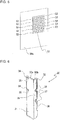
- Fig. 4 is a perspective view of the shell panel constituting part of the casing of the air-conditioning-apparatus outdoor unit according to Embodiment 1 of the present invention.
- Fig. 5 is an enlarged perspective view illustrating the outdoor-air inlet as viewed from the outside of the casing of the air-conditioning-apparatus outdoor unit according to Embodiment 1 of the present invention.
- the shell panel 50a is made of a plate, such as a steel sheet, extending in a height direction of the outdoor unit and has an L-shaped cross section. As illustrated in Fig. 4 , the shell panel 50a has the outdoor-air inlet 51 for sucking the outdoor air.
- the outdoor-air inlet 51 is open and positioned to face the heat exchanger pipes 8 on the first end of the heat exchanger 6. As illustrated in Fig. 5 , the outdoor-air inlet 51 includes a plurality of truncated pyramid-shaped protrusions 52 outwardly protruding from the shell panel 50a. The outermost part of each protrusion 52 is open. The outside and inside of the outdoor unit 100 communicate with each other through the open outermost part of the protrusion 52. Although ten protrusions 52 are arranged in Fig. 5 , any number of protrusions 52 may be arranged. Although each protrusion 52 is truncated pyramid-shaped, the protrusion 52 may be, for example, truncated cone-shaped, hemispherical shaped, cylinder-shaped, or prism-shaped.
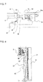
- Fig. 6 is a perspective view of the heat exchanger cover of the air-conditioning-apparatus outdoor unit according to Embodiment 1 of the present invention.
- the heat exchanger cover 30 is made of a plate, such as a steel sheet, extending in the height direction of the outdoor unit and has an L-shaped cross section.
- the heat exchanger cover 30 includes a first flat portion 31, which defines a wide side wall in the L-shaped cross section and faces the heat exchanger pipes 8 and the outdoor-air inlet 51, and a second flat portion 32, which defines a narrow side wall in the L-shaped cross section and connects to the first flat portion 31.
- the heat exchanger cover 30 includes a plate 34 disposed at an upper end position of a side end of the first flat portion 31 in a height direction of the side end and another plate 34 disposed at an intermediate position of the side end in the height direction of the side end.
- the plates 34 are angled inward in the L-shaped cross section.
- the plates 34 each have a screw hole 35, through which a screw extends. These screws extend through the screw holes 23 of the partition 20 and are secured to the heat exchanger end plate 9. Consequently, the heat exchanger cover 30 is joined and fixed to the partition 20 and the heat exchanger 6.
- the heat exchanger cover 30 further has a screw hole 36 at an intermediate position of a side end of the second flat portion 32 in a height direction of the side end.
- a screw extends through the screw hole 36 and is secured to the shell panel 50a. Consequently, the heat exchanger cover 30 is joined and fixed to the shell panel 50a.
- the heat exchanger cover 30 is positioned to face the heat exchanger pipes 8 and the outdoor-air inlet 51.
- the heat exchanger cover 30 partially covers the heat exchanger pipes 8, and defines, together with the partition 20, the heat exchanger 6, and the shell panel 50a, the air passage 40 communicating with the outdoor-air inlet 51 in the machine chamber 3.
- the heat exchanger cover 30 further has two U-shaped pipe openings 37 at intermediate positions of the side end of the second flat portion 32 in the height direction of the side end.
- the pipe openings 37 receive pipe holders 38, each through which a corresponding one of the inlet pipe 10 and the outlet pipe 11 extends.
- the heat exchanger cover 30 includes a first upper end 33a, formed by bending upper end part of the first flat portion 31 outwardly in the L-shaped cross section, and a second upper end 33b, formed by bending upper end part of the second flat portion 32 outwardly in the L-shaped cross section.
- the electric box 5 is connected and fixed to the first upper end 33a and the second upper end 33b.
- Fig. 7 is a transverse sectional view of essential part of the air-conditioning-apparatus outdoor unit according to Embodiment 1 of the present invention.
- Fig. 8 is a longitudinal sectional view of essential part of the air-conditioning-apparatus outdoor unit according to Embodiment 1 of the present invention.
- the flow of air in the outdoor unit 100 will be described below with reference to Figs. 1 , 7, and 8 .
- outlined arrows indicate the flow of outdoor air.
- Activation of the air-sending device 7 creates a negative pressure in a space defined by the air-sending device 7 and the heat exchanger 6 in the air-sending device chamber 2.
- the communication openings 24 in the partition 20 communicate with the side vent 66 in the first side plate 61 of the electric box 5, and the bottom opening 62 in the bottom plate 60 of the electric box 5 communicates with the air passage 40, so that the space under the negative pressure in the air-sending device chamber 2 communicates with the outdoor-air inlet 51. Consequently, the negative pressure in the space defined by the air-sending device 7 and the heat exchanger 6 in the air-sending device chamber 2 causes the outdoor air to be sucked into the air passage 40 through the outdoor-air inlet 51.
- the outdoor air sucked into the air passage 40 is drawn to the electric box 5 disposed on the heat exchanger cover 30 and is sucked into the electric box 5 through, for example, the bottom opening 62 in the bottom plate 60 of the electric box 5.
- the outdoor air, sucked into the electric box 5 cools electric components while passing through the inside of the electric box 5.
- the outdoor air sucked into the electric box 5 is sucked into the air-sending device chamber 2 through the side vent 66 located in the first side plate 61 of the electric box 5 and the communication openings 24 located in the partition 20.
- the outdoor air sucked into the air-sending device chamber 2 is sent to the outside of the outdoor unit 100 by the air-sending device 7.
- the heat exchanger cover 30 defining the air passage regulates the air flow, thus allowing the outdoor air to efficiently flow to the electric box 5.
- the outdoor-air inlet 51 serving as an outdoor-air intake, may serve as an entrance for water, such as rain.
- the outdoor unit 100 includes the heat exchanger cover 30.
- the heat exchanger cover 30 covers the heat exchanger pipes 8 and the outdoor-air inlet 51 and thus minimizes the entry of rainwater.
- This configuration can prevent, for example, electric components and wiring lines in the machine chamber 3 from getting wet, thus preventing, for example, corrosion of structural parts in the machine chamber 3 and a short circuit in the electric components in the machine chamber 3.
- the outdoor-air inlet 51 in the shell panel 50a includes the protrusions 52.
- the protrusions 52 each serving as a canopy, can minimize the entry of rain.
- the heat exchanger cover 30 defining the air passage regulates the flow of air, thus allowing the outdoor air to efficiently flow to the electric box 5.
- a traditional air-conditioning-apparatus outdoor unit may fail to sufficiently cool an electric box because an inlet to suck air for cooling electric components is located at a distance from the electric box and the air fails to flow properly.
- the heat exchanger cover 30, which covers and surrounds the pipes of the heat exchanger and defines the air passage for cooling the electric components, enables the air to efficiently flow to the electric box.
- the heat exchanger cover 30 covering and surrounding the heat exchanger pipes 8 allows the outdoor air flowing through the air passage 40 to contact the heat exchanger pipes 8, thus achieving heat exchange between the outdoor air and the heat exchanger pipes 8.
- This configuration maximizes the capacity of the heat exchanger 6, thus enhancing the performance of the air-conditioning apparatus.
- Embodiments of the present invention are not limited to Embodiment 1 described above.
- the bottom plate 60 has the four bottom openings, that is, the bottom opening 62, the bottom opening 63, the bottom opening 64, and the bottom opening 65
- the bottom plate 60 may have one bottom opening or may have a plurality of bottom openings.
- the bottom opening 62 includes the step portion protruding toward the air passage 40 and the interstep portions each have an opening
- the bottom opening 62 may be a slit with no step portion.
- the shell panel 50a is made of a plate, such as a steel sheet, extending in the height direction and has an L-shaped cross section
- the shell panel 50a may be a flat plate defining one side surface of the casing 50.
- the outdoor-air inlet 51 includes the plurality of protrusions 52 protruding outwardly from the shell panel 50a
- the outdoor-air inlet 51 may include flat slits.
Landscapes
- Engineering & Computer Science (AREA)
- Chemical & Material Sciences (AREA)
- Combustion & Propulsion (AREA)
- Mechanical Engineering (AREA)
- General Engineering & Computer Science (AREA)
- Other Air-Conditioning Systems (AREA)
Abstract
Description
- The present invention relates to an air-conditioning-apparatus outdoor unit including a casing and a partition disposed in the casing.
- Atypical outdoor unit has an air-sending chamber accommodating a heat exchanger and an air-sending device and a machine chamber accommodating a compressor and an electric component, and the air-sending chamber is separated from the machine chamber by a partition. In such an outdoor unit, the compressor and the electric component emit heat in the machine chamber. To dissipate heat from the compressor and the electric component, some of such outdoor units include a shell panel in a casing of the outdoor unit having an air inlet through which outdoor air is sucked into the machine chamber (refer to Patent Literature 1, for example).
- Patent Literature 1: Japanese Examined Utility Model Registration Application Publication No.
63-010421 - An air-conditioning apparatus disclosed in Patent Literature 1 includes a front panel located in a space from which an air-sending device sucks air, and the front panel has an air inlet. When it rains, for example, rainwater may enter the outdoor unit and lead to corrosion of structural parts in the outdoor unit or a short circuit in the electric component disposed in the outdoor unit.
- The present invention aims to overcome the above-described disadvantages and provide an air-conditioning-apparatus outdoor unit that has an air inlet for sucking air for a machine chamber and that prevents, for example, corrosion of structural parts in the outdoor unit and a short circuit in an electric component disposed in the outdoor unit.
- An air-conditioning-apparatus outdoor unit according to an embodiment of the present invention includes a casing constituting a shell of the outdoor unit, an air-sending device chamber disposed in the casing and accommodating a heat exchanger and an air-sending device, a machine chamber disposed in the casing and accommodating a compressor, a partition separating the air-sending device chamber from the machine chamber, a heat exchanger cover having an L-shaped cross section and including a first flat portion that defines a first side wall of the heat exchanger cover and that is joined to the partition and a second flat portion that defines a second side wall of the heat exchanger cover and that is joined to the casing, and an electric box including a bottom plate that defines a bottom surface of the electric box and that is joined to an upper end of the heat exchanger cover. The casing includes a shell panel having an outdoor-air inlet that is open. The heat exchanger cover is positioned to face the outdoor-air inlet, and defines, together with the partition and the shell panel, an air passage communicating with the outdoor-air inlet in the machine chamber. The bottom plate of the electric box has a bottom opening communicating with the air passage.
- In an air-conditioning-apparatus outdoor unit according to an embodiment of the present invention, the casing includes the shell panel having the outdoor-air inlet that is open and positioned to face a pipe on one end of the heat exchanger. The heat exchanger cover is positioned to face the pipe and the outdoor-air inlet. This configuration enables outdoor air to be sucked into the machine chamber, and minimizes the entry of rainwater to prevent, for example, corrosion of structural parts in the machine chamber and a short circuit in an electric component disposed in the machine chamber.
-
-
Fig. 1 is a schematic perspective view illustrating the inside of an air-conditioning-apparatus outdoor unit according to Embodiment 1 of the present invention. -
Fig. 2 is a sectional view taken along the line A-A inFig. 1 . -
Fig. 3 is a sectional view taken along the line B-B inFig. 1 . -
Fig. 4 is a perspective view of a shell panel constituting part of a casing of the air-conditioning-apparatus outdoor unit according to Embodiment 1 of the present invention. -
Fig. 5 is an enlarged perspective view illustrating an outdoor-air inlet as viewed from the outside of the casing of the air-conditioning-apparatus outdoor unit according to Embodiment 1 of the present invention. -
Fig. 6 is a perspective view of a heat exchanger cover of the air-conditioning-apparatus outdoor unit according to Embodiment 1 of the present invention. -
Fig. 7 is a transverse sectional view of essential part of the air-conditioning-apparatus outdoor unit according to Embodiment 1 of the present invention. -
Fig. 8 is a longitudinal sectional view of essential part of the air-conditioning-apparatus outdoor unit according to Embodiment 1 of the present invention. - An
outdoor unit 100 of an air-conditioning apparatus in the present invention will be described below in detail with reference to the drawings. Note that the relative sizes of components illustrated in the following figures may differ from the actual sizes of the components. Furthermore, note that components denoted by the same reference sings in the following figures are the same components or equivalents. This note applies to the following description of the specification. Furthermore, note that the forms of components described in the specification are illustrative only, and the forms of components are not limited to those in the descriptions. -
Fig. 1 is a schematic perspective view illustrating the inside of the air-conditioning-apparatus outdoor unit according to Embodiment 1 of the present invention. As illustrated inFig. 1 , the inside of theoutdoor unit 100 is divided into an air-sending device chamber 2 and amachine chamber 3 by apartition 20. Theoutdoor unit 100 includes ashell panel 50a, serving as part of acasing 50 included in a body of theoutdoor unit 100. The air-sending device chamber 2 accommodates, for example, aheat exchanger 6 and an air-sending device 7. Themachine chamber 3 accommodates, for example, acompressor 4, a refrigerant pipe (not illustrated), and anelectric box 5. The inside of themachine chamber 3 is divided into sections by aheat exchanger cover 30, thus forming anair passage 40. Thecompressor 4 and theheat exchanger 6 are installed on a bottom plate 1. - The
partition 20 includes avertical portion 21 upwardly extending from the bottom plate 1 and provided between a front panel of theoutdoor unit 100 and theheat exchanger 6 and anangled portion 22 angled from an end of one of long sides of thevertical portion 21 toward themachine chamber 3. Thepartition 20 is formed by bending, for example, a metal sheet. Theangled portion 22 hasscrew holes 23, which are through-holes. Thescrew holes 23 may be blind holes, such as recesses. Thepartition 20 hascommunication openings 24, through which the air-sending device chamber 2 communicates with themachine chamber 3, in upper part of thepartition 20. InFig. 1 , thepartition 20 has twocommunication openings 24. Thepartition 20 may have one communication opening. - The
heat exchanger 6 allows heat exchange between outdoor air and refrigerant, acts as an evaporator during a heating operation, and acts as a condenser during a cooling operation. Theheat exchanger 6 includes heat transfer tubes, through which the refrigerant passes, and fins for increasing the area of heat transfer between the outdoor air and the refrigerant flowing through the heat transfer tubes. Theheat exchanger 6 is L-shaped in such a manner that theheat exchanger 6 includes flat portions and a curved portion. Although the L-shaped heat exchanger 6 is illustrated as an example, theheat exchanger 6 may be flat or may be U-shaped and include curved portions in both ends of theheat exchanger 6. Theheat exchanger 6 includesheat exchanger pipes 8, serving as electric heating pipes, protruding toward themachine chamber 3 and a heatexchanger end plate 9, through which theheat exchanger pipes 8 extend, disposed on a first end of theheat exchanger 6. Theheat exchanger 6 further includes aninlet pipe 10 and anoutlet pipe 11 protruding from the first end toward themachine chamber 3. Theinlet pipe 10 is connected to a discharge pipe connected to thecompressor 4, and theoutlet pipe 11 is connected to an expansion pipe of an expansion unit, thus forming a refrigerant circuit. When the flow of the refrigerant is reversed, theinlet pipe 10 is connected to the expansion pipe of the expansion unit, and theoutlet pipe 11 is connected to the discharge pipe. - The air-
sending device 7 is an air-sending unit including apropeller fan 7a and a motor, and produces air circulation for efficient heat exchange. The air-sendingdevice 7 has a function of sucking the outdoor air into theoutdoor unit 100 from a rear of theoutdoor unit 100 and discharging the outdoor air sucked into theoutdoor unit 100 toward a front of theoutdoor unit 100. The air-sending device 7 further has a function of creating a negative pressure in a space defined by theheat exchanger 6 and thepropeller fan 7a and directing the outdoor air sucked from an outdoor-air inlet 51 in theshell panel 50a to theelectric box 5 via theair passage 40. - The
compressor 4 is, for example, a rotary type, scroll type, or vane type compressor whose capacity can be controlled by driving the compressor under control of an inverter. Thecompressor 4 compresses sucked refrigerant into high-temperature, high-pressure gas refrigerant and discharges the refrigerant. - The
electric box 5 accommodates control components for controlling an operation of theoutdoor unit 100. Examples of the control components include hardware, such as a circuit device, implementing such a function, software to run on a microcomputer or an arithmetic unit, such as a central processing unit, and a combination of hardware and software. Theelectric box 5 includes abottom plate 60 defining a bottom surface of theelectric box 5 and afirst side plate 61 defining a side surface facing thepartition 20. Thebottom plate 60 has abottom opening 62, abottom opening 63, abottom opening 64, and abottom opening 65, which communicate with theair passage 40. Thefirst side plate 61 has aside vent 66, which is open and communicates with thecommunication openings 24 of thepartition 20. -
Fig. 2 is a sectional view taken along the line A-A inFig. 1 . InFig. 2 , dotted-line arrows indicate the flow of air. As thebottom opening 62, thebottom opening 63, thebottom opening 64, and thebottom opening 65 have the same structure, only thebottom opening 62 will be described. As illustrated inFig. 2 , thebottom plate 60 has thebottom opening 62, and thebottom opening 62 includes step portions protruding toward theair passage 40. Thebottom opening 62 includes aninterstep portion 73a and aninterstep portion 73b, which each are angled from afirst bottom portion 71 to asecond bottom portion 72. Theinterstep portion 73a has anopening 74a, and theinterstep portion 73b has anopening 74b. In other words, thebottom plate 60 has a plurality of protruding parts on its lower surface when thebottom plate 60 is viewed as a horizontal plane. -
Fig. 3 is a sectional view taken along the line B-B inFig. 1 . InFig. 3 , dotted-line arrows indicate the flow of air. Thefirst side plate 61 has theside vent 66, and theside vent 66 includes a step portion protruding away from thepartition 20. The side vent 66 includes aninterstep portion 77a and aninterstep portion 77b, which each are angled from afirst side portion 75 to asecond side portion 76. Theinterstep portion 77a has anopening 78a, and theinterstep portion 77b has anopening 78b. -
Fig. 4 is a perspective view of the shell panel constituting part of the casing of the air-conditioning-apparatus outdoor unit according to Embodiment 1 of the present invention.Fig. 5 is an enlarged perspective view illustrating the outdoor-air inlet as viewed from the outside of the casing of the air-conditioning-apparatus outdoor unit according to Embodiment 1 of the present invention. Theshell panel 50a is made of a plate, such as a steel sheet, extending in a height direction of the outdoor unit and has an L-shaped cross section. As illustrated inFig. 4 , theshell panel 50a has the outdoor-air inlet 51 for sucking the outdoor air. The outdoor-air inlet 51 is open and positioned to face theheat exchanger pipes 8 on the first end of theheat exchanger 6. As illustrated inFig. 5 , the outdoor-air inlet 51 includes a plurality of truncated pyramid-shapedprotrusions 52 outwardly protruding from theshell panel 50a. The outermost part of eachprotrusion 52 is open. The outside and inside of theoutdoor unit 100 communicate with each other through the open outermost part of theprotrusion 52. Although tenprotrusions 52 are arranged inFig. 5 , any number ofprotrusions 52 may be arranged. Although eachprotrusion 52 is truncated pyramid-shaped, theprotrusion 52 may be, for example, truncated cone-shaped, hemispherical shaped, cylinder-shaped, or prism-shaped. -
Fig. 6 is a perspective view of the heat exchanger cover of the air-conditioning-apparatus outdoor unit according to Embodiment 1 of the present invention. Theheat exchanger cover 30 is made of a plate, such as a steel sheet, extending in the height direction of the outdoor unit and has an L-shaped cross section. Theheat exchanger cover 30 includes a firstflat portion 31, which defines a wide side wall in the L-shaped cross section and faces theheat exchanger pipes 8 and the outdoor-air inlet 51, and a secondflat portion 32, which defines a narrow side wall in the L-shaped cross section and connects to the firstflat portion 31. - The
heat exchanger cover 30 includes aplate 34 disposed at an upper end position of a side end of the firstflat portion 31 in a height direction of the side end and anotherplate 34 disposed at an intermediate position of the side end in the height direction of the side end. Theplates 34 are angled inward in the L-shaped cross section. Theplates 34 each have ascrew hole 35, through which a screw extends. These screws extend through the screw holes 23 of thepartition 20 and are secured to the heatexchanger end plate 9. Consequently, theheat exchanger cover 30 is joined and fixed to thepartition 20 and theheat exchanger 6. Theheat exchanger cover 30 further has ascrew hole 36 at an intermediate position of a side end of the secondflat portion 32 in a height direction of the side end. A screw extends through thescrew hole 36 and is secured to theshell panel 50a. Consequently, theheat exchanger cover 30 is joined and fixed to theshell panel 50a. Theheat exchanger cover 30 is positioned to face theheat exchanger pipes 8 and the outdoor-air inlet 51. Theheat exchanger cover 30 partially covers theheat exchanger pipes 8, and defines, together with thepartition 20, theheat exchanger 6, and theshell panel 50a, theair passage 40 communicating with the outdoor-air inlet 51 in themachine chamber 3. - The
heat exchanger cover 30 further has twoU-shaped pipe openings 37 at intermediate positions of the side end of the secondflat portion 32 in the height direction of the side end. Thepipe openings 37 receivepipe holders 38, each through which a corresponding one of theinlet pipe 10 and theoutlet pipe 11 extends. - The
heat exchanger cover 30 includes a firstupper end 33a, formed by bending upper end part of the firstflat portion 31 outwardly in the L-shaped cross section, and a secondupper end 33b, formed by bending upper end part of the secondflat portion 32 outwardly in the L-shaped cross section. Theelectric box 5 is connected and fixed to the firstupper end 33a and the secondupper end 33b. -
Fig. 7 is a transverse sectional view of essential part of the air-conditioning-apparatus outdoor unit according to Embodiment 1 of the present invention.Fig. 8 is a longitudinal sectional view of essential part of the air-conditioning-apparatus outdoor unit according to Embodiment 1 of the present invention. The flow of air in theoutdoor unit 100 will be described below with reference toFigs. 1 ,7, and 8 . InFigs. 7 and 8 , outlined arrows indicate the flow of outdoor air. - Activation of the air-sending
device 7 creates a negative pressure in a space defined by the air-sendingdevice 7 and theheat exchanger 6 in the air-sending device chamber 2. Thecommunication openings 24 in thepartition 20 communicate with theside vent 66 in thefirst side plate 61 of theelectric box 5, and thebottom opening 62 in thebottom plate 60 of theelectric box 5 communicates with theair passage 40, so that the space under the negative pressure in the air-sending device chamber 2 communicates with the outdoor-air inlet 51. Consequently, the negative pressure in the space defined by the air-sendingdevice 7 and theheat exchanger 6 in the air-sending device chamber 2 causes the outdoor air to be sucked into theair passage 40 through the outdoor-air inlet 51. The outdoor air sucked into theair passage 40 is drawn to theelectric box 5 disposed on theheat exchanger cover 30 and is sucked into theelectric box 5 through, for example, thebottom opening 62 in thebottom plate 60 of theelectric box 5. The outdoor air, sucked into theelectric box 5, cools electric components while passing through the inside of theelectric box 5. Subsequently, the outdoor air sucked into theelectric box 5 is sucked into the air-sending device chamber 2 through theside vent 66 located in thefirst side plate 61 of theelectric box 5 and thecommunication openings 24 located in thepartition 20. The outdoor air sucked into the air-sending device chamber 2 is sent to the outside of theoutdoor unit 100 by the air-sendingdevice 7. - As described above, the
heat exchanger cover 30 defining the air passage regulates the air flow, thus allowing the outdoor air to efficiently flow to theelectric box 5. Unfortunately, the outdoor-air inlet 51, serving as an outdoor-air intake, may serve as an entrance for water, such as rain. For this reason, theoutdoor unit 100 includes theheat exchanger cover 30. As theheat exchanger cover 30 is positioned to face theheat exchanger pipes 8 and the outdoor-air inlet 51, theheat exchanger cover 30 covers theheat exchanger pipes 8 and the outdoor-air inlet 51 and thus minimizes the entry of rainwater. This configuration can prevent, for example, electric components and wiring lines in themachine chamber 3 from getting wet, thus preventing, for example, corrosion of structural parts in themachine chamber 3 and a short circuit in the electric components in themachine chamber 3. - The outdoor-
air inlet 51 in theshell panel 50a includes theprotrusions 52. Theprotrusions 52, each serving as a canopy, can minimize the entry of rain. - In addition, the
heat exchanger cover 30 defining the air passage regulates the flow of air, thus allowing the outdoor air to efficiently flow to theelectric box 5. Specifically, a traditional air-conditioning-apparatus outdoor unit may fail to sufficiently cool an electric box because an inlet to suck air for cooling electric components is located at a distance from the electric box and the air fails to flow properly. Theheat exchanger cover 30, which covers and surrounds the pipes of the heat exchanger and defines the air passage for cooling the electric components, enables the air to efficiently flow to the electric box. - Furthermore, the
heat exchanger cover 30 covering and surrounding theheat exchanger pipes 8 allows the outdoor air flowing through theair passage 40 to contact theheat exchanger pipes 8, thus achieving heat exchange between the outdoor air and theheat exchanger pipes 8. This configuration maximizes the capacity of theheat exchanger 6, thus enhancing the performance of the air-conditioning apparatus. - Embodiments of the present invention are not limited to Embodiment 1 described above. For example, although the
bottom plate 60 has the four bottom openings, that is, thebottom opening 62, thebottom opening 63, thebottom opening 64, and thebottom opening 65, thebottom plate 60 may have one bottom opening or may have a plurality of bottom openings. Furthermore, although thebottom opening 62 includes the step portion protruding toward theair passage 40 and the interstep portions each have an opening, thebottom opening 62 may be a slit with no step portion. In addition, although theshell panel 50a is made of a plate, such as a steel sheet, extending in the height direction and has an L-shaped cross section, theshell panel 50a may be a flat plate defining one side surface of thecasing 50. Furthermore, although the outdoor-air inlet 51 includes the plurality ofprotrusions 52 protruding outwardly from theshell panel 50a, the outdoor-air inlet 51 may include flat slits. - 1 bottom plate 2 air-sending
device chamber 3machine chamber 4compressor 5electric box 6heat exchanger 7 air-sendingdevice 7a propeller fan 8heat exchanger pipe 9 heatexchanger end plate 10inlet pipe 11outlet pipe 20partition 21vertical portion 22 slopingportion 23screw hole 24communication opening 30heat exchanger cover 31 firstflat portion 32 secondflat portion 33a firstupper end 33b secondupper end 34plate 35screw hole 36screw hole 37pipe opening 38pipe holder 40air passage 50casing 50a shell panel 51 outdoor-air inlet 52protrusion 60bottom plate 61first side plate 62 bottom opening 63bottom opening 64bottom opening 65bottom opening 66 side vent 71first bottom portion 72second bottom portion 73ainterstep portion 73binterstep 74b opening 75portion 74a openingfirst side portion 76second side portion 77ainterstep portion 77binterstep 100 outdoor unitportion 78aopening 78b opening
Claims (5)
- An outdoor unit of an air-conditioning apparatus, the outdoor unit comprising:a casing constituting a shell of the outdoor unit;an air-sending device chamber disposed in the casing, the air-sending device chamber accommodating a heat exchanger and an air-sending device;a machine chamber disposed in the casing, the machine chamber accommodating a compressor;a partition separating the air-sending device chamber from the machine chamber;a heat exchanger cover having an L-shaped cross section and including a first flat portion defining a first side wall of the heat exchanger cover and a second flat portion defining a second side wall of the heat exchanger cover, the first flat portion being joined to the partition, the second flat portion being joined to the casing; andan electric box including a bottom plate defining a bottom surface of the electric box, the bottom plate being joined to an upper end of the heat exchanger cover,the casing including a shell panel having an outdoor-air inlet that is open,the heat exchanger cover being positioned to face the outdoor-air inlet, and defining, together with the partition and the shell panel, an air passage communicating with the outdoor-air inlet in the machine chamber,the bottom plate of the electric box having a bottom opening communicating with the air passage.
- The outdoor unit of an air-conditioning apparatus of claim 1,
wherein the partition has a communication opening, through which the air-sending device chamber communicates with the machine chamber, in upper part of the partition, and
wherein the electric box includes a first side plate defining a side wall of the electric box, and the first side plate has a side vent that is open and positioned to face the communication opening. - The outdoor unit of an air-conditioning apparatus of claim 1 or 2,
wherein the outdoor-air inlet of the shell panel is positioned to face a pipe on one end of the heat exchanger, and
wherein the heat exchanger cover is positioned to face the pipe. - The outdoor unit of an air-conditioning apparatus of any one of claims 1 to 3, wherein the heat exchanger cover has pipe openings each through which a corresponding one of an inlet pipe and an outlet pipe extends, the inlet pipe and the outlet pipe each connecting the heat exchanger to the compressor.
- The outdoor unit of an air-conditioning apparatus of any one of claims 1 to 4, wherein the shell panel includes a protrusion protruding outwardly from the casing, and the outdoor-air inlet is disposed in the protrusion.
Applications Claiming Priority (1)
| Application Number | Priority Date | Filing Date | Title |
|---|---|---|---|
| PCT/JP2016/064174 WO2017195335A1 (en) | 2016-05-12 | 2016-05-12 | Outdoor unit of air conditioner |
Publications (3)
| Publication Number | Publication Date |
|---|---|
| EP3457037A1 true EP3457037A1 (en) | 2019-03-20 |
| EP3457037A4 EP3457037A4 (en) | 2019-05-22 |
| EP3457037B1 EP3457037B1 (en) | 2022-02-23 |
Family
ID=60267021
Family Applications (1)
| Application Number | Title | Priority Date | Filing Date |
|---|---|---|---|
| EP16901683.9A Active EP3457037B1 (en) | 2016-05-12 | 2016-05-12 | Outdoor unit of air conditioner |
Country Status (5)
| Country | Link |
|---|---|
| US (1) | US10731875B2 (en) |
| EP (1) | EP3457037B1 (en) |
| JP (1) | JP6661757B2 (en) |
| CN (1) | CN109154447B (en) |
| WO (1) | WO2017195335A1 (en) |
Families Citing this family (5)
| Publication number | Priority date | Publication date | Assignee | Title |
|---|---|---|---|---|
| JP6593402B2 (en) * | 2017-08-09 | 2019-10-23 | ダイキン工業株式会社 | Refrigeration unit outdoor unit |
| US10578321B2 (en) * | 2018-03-21 | 2020-03-03 | Haier Us Appliance Solutions, Inc. | Air conditioner unit with selective cooling of an indoor fan motor |
| JP6974754B2 (en) * | 2019-09-18 | 2021-12-01 | ダイキン工業株式会社 | Outdoor unit of refrigeration equipment |
| US11635214B2 (en) | 2019-12-20 | 2023-04-25 | Johnson Controls Tyco IP Holdings LLP | Base pan for HVAC system |
| CN112178793A (en) * | 2020-10-29 | 2021-01-05 | 珠海格力电器股份有限公司 | Air conditioner external unit chassis, air conditioner and air conditioner compressor heat dissipation control method |
Family Cites Families (33)
| Publication number | Priority date | Publication date | Assignee | Title |
|---|---|---|---|---|
| JPS58141163U (en) | 1982-03-16 | 1983-09-22 | 三洋電機株式会社 | air conditioner |
| JPS6083868U (en) * | 1983-11-16 | 1985-06-10 | 三洋電機株式会社 | heat exchange unit |
| JPH0719513B2 (en) | 1986-06-27 | 1995-03-06 | 株式会社明電舎 | Vacuum interrupter |
| JPS6332239U (en) | 1986-08-14 | 1988-03-02 | ||
| JPH02115634A (en) | 1988-10-24 | 1990-04-27 | Toshiba Corp | Outdoor device for air conditioner |
| JPH0373843U (en) | 1989-11-20 | 1991-07-25 | ||
| JPH03118444U (en) | 1990-03-14 | 1991-12-06 | ||
| JPH0579661A (en) | 1991-09-19 | 1993-03-30 | Mitsubishi Electric Corp | Outdoor unit for air-conditioning machine and electric appliance therefor |
| JPH05231677A (en) * | 1992-02-18 | 1993-09-07 | Mitsubishi Electric Corp | Outdoor unit of air conditioner |
| JP4305999B2 (en) * | 1999-03-24 | 2009-07-29 | 三菱電機株式会社 | Air conditioner outdoor unit |
| JP4341376B2 (en) * | 2003-11-07 | 2009-10-07 | 三菱電機株式会社 | Air conditioner |
| KR101298404B1 (en) * | 2007-09-21 | 2013-08-20 | 엘지전자 주식회사 | Out door unit of an air conditioner |
| JP2009030829A (en) * | 2007-07-25 | 2009-02-12 | Sanyo Electric Co Ltd | Air conditioning device |
| CN101586844B (en) * | 2008-05-23 | 2013-04-10 | 乐金电子(天津)电器有限公司 | Outdoor machine of air conditioner |
| KR101575904B1 (en) * | 2009-01-09 | 2015-12-08 | 엘지전자 주식회사 | Fan motor mounting structure and outdoor unit of air conditioner including the same |
| JP5849396B2 (en) * | 2011-01-31 | 2016-01-27 | 株式会社富士通ゼネラル | Air conditioner outdoor unit |
| EP2525158A3 (en) * | 2011-05-17 | 2018-08-15 | Sanyo Electric Co., Ltd. | Outdoor unit for air conditioner |
| JP5923950B2 (en) * | 2011-11-30 | 2016-05-25 | 株式会社富士通ゼネラル | Air conditioner outdoor unit |
| US20130255932A1 (en) * | 2012-03-30 | 2013-10-03 | Emerson Climate Technologies, Inc. | Heat sink for a condensing unit and method of using same |
| JP2013228167A (en) * | 2012-04-26 | 2013-11-07 | Daikin Industries Ltd | Humidity control device |
| JP2014105948A (en) * | 2012-11-29 | 2014-06-09 | Fujitsu General Ltd | Outdoor unit of air conditioner |
| JP2014115023A (en) * | 2012-12-10 | 2014-06-26 | Mitsubishi Electric Corp | Outdoor machine of air conditioner |
| JP6085967B2 (en) * | 2012-12-26 | 2017-03-01 | 株式会社ノーリツ | Heat exchanger and water heater provided with the same |
| JP6217969B2 (en) * | 2013-08-23 | 2017-10-25 | ダイキン工業株式会社 | Cooling structure in the machine room of an outdoor unit of an air conditioner |
| KR102166764B1 (en) * | 2013-10-10 | 2020-10-19 | 삼성전자주식회사 | Control box and outdoor unit for air conditioner |
| KR102116568B1 (en) * | 2013-10-14 | 2020-06-01 | 엘지전자 주식회사 | An air conditioner |
| KR102170317B1 (en) * | 2014-01-14 | 2020-10-26 | 엘지전자 주식회사 | Outdoor unit control for air conditoiner |
| CN103776106B (en) * | 2014-01-27 | 2016-08-17 | 广东美的制冷设备有限公司 | Air exchangeable conditioner system |
| JP6177158B2 (en) * | 2014-02-25 | 2017-08-09 | ジョンソンコントロールズ ヒタチ エア コンディショニング テクノロジー(ホンコン)リミテッド | Air conditioner |
| JP6203112B2 (en) | 2014-04-25 | 2017-09-27 | 三菱電機株式会社 | Air conditioner outdoor unit |
| CN203980456U (en) * | 2014-06-24 | 2014-12-03 | 广东美的制冷设备有限公司 | Heating and air conditioner |
| CN204786877U (en) * | 2015-05-28 | 2015-11-18 | 广东美的制冷设备有限公司 | Air condensing units and one drag many air conditioners |
| CN105157127B (en) * | 2015-06-30 | 2019-02-12 | 广东美的制冷设备有限公司 | Air conditioner electronically controlled cooling system and cooling method |
-
2016
- 2016-05-12 CN CN201680085405.7A patent/CN109154447B/en active Active
- 2016-05-12 EP EP16901683.9A patent/EP3457037B1/en active Active
- 2016-05-12 JP JP2018516299A patent/JP6661757B2/en not_active Expired - Fee Related
- 2016-05-12 WO PCT/JP2016/064174 patent/WO2017195335A1/en not_active Ceased
- 2016-05-12 US US16/080,799 patent/US10731875B2/en not_active Expired - Fee Related
Also Published As
| Publication number | Publication date |
|---|---|
| US10731875B2 (en) | 2020-08-04 |
| JP6661757B2 (en) | 2020-03-11 |
| CN109154447A (en) | 2019-01-04 |
| EP3457037B1 (en) | 2022-02-23 |
| JPWO2017195335A1 (en) | 2018-11-22 |
| CN109154447B (en) | 2021-10-29 |
| EP3457037A4 (en) | 2019-05-22 |
| WO2017195335A1 (en) | 2017-11-16 |
| US20190145637A1 (en) | 2019-05-16 |
Similar Documents
| Publication | Publication Date | Title |
|---|---|---|
| EP3457037B1 (en) | Outdoor unit of air conditioner | |
| CN103608629B (en) | Built-in air-conditioning system | |
| KR20190004118A (en) | Window type air conditioner | |
| JP2000161717A (en) | Outdoor unit of air conditioner | |
| CN101520210A (en) | Indoor built-in type heat source unit | |
| EP3392573B1 (en) | Outdoor machine for freezing cycle apparatus | |
| US11859859B2 (en) | Outdoor unit for air-conditioning apparatus | |
| JP2000275372A (en) | Outdoor unit of air conditioner | |
| JP2018119718A (en) | Embedded ceiling air conditioner | |
| KR100529919B1 (en) | An indoor unit of air-conditioner | |
| JP2000320856A (en) | Cross flow fan | |
| JP2018119714A (en) | Embedded ceiling air conditioner | |
| KR102522048B1 (en) | Ceiling type air conditioner | |
| JP2018119713A (en) | Ceiling-embedded air conditioner | |
| CN221991919U (en) | Air conditioner | |
| KR100854324B1 (en) | Ceiling air conditioners | |
| KR20250072747A (en) | Air conditioner | |
| JP2018119715A (en) | Ceiling-embedded air conditioner | |
| JP2018185121A (en) | Air conditioner indoor unit | |
| CN109442578A (en) | Air conditioner | |
| JP2023173582A (en) | Air conditioning indoor unit, and air conditioning device | |
| CN114391081A (en) | Outdoor unit of refrigerating apparatus | |
| JP2018119721A (en) | Ceiling-embedded air conditioner | |
| KR20020082262A (en) | Heat-exchanger mounting structure for air conditioner | |
| JP2018119716A (en) | Embedded ceiling air conditioner |
Legal Events
| Date | Code | Title | Description |
|---|---|---|---|
| STAA | Information on the status of an ep patent application or granted ep patent |
Free format text: STATUS: THE INTERNATIONAL PUBLICATION HAS BEEN MADE |
|
| PUAI | Public reference made under article 153(3) epc to a published international application that has entered the european phase |
Free format text: ORIGINAL CODE: 0009012 |
|
| STAA | Information on the status of an ep patent application or granted ep patent |
Free format text: STATUS: REQUEST FOR EXAMINATION WAS MADE |
|
| 17P | Request for examination filed |
Effective date: 20181026 |
|
| AK | Designated contracting states |
Kind code of ref document: A1 Designated state(s): AL AT BE BG CH CY CZ DE DK EE ES FI FR GB GR HR HU IE IS IT LI LT LU LV MC MK MT NL NO PL PT RO RS SE SI SK SM TR |
|
| AX | Request for extension of the european patent |
Extension state: BA ME |
|
| REG | Reference to a national code |
Ref country code: DE Ref legal event code: R079 Ref document number: 602016069475 Country of ref document: DE Free format text: PREVIOUS MAIN CLASS: F24F0001560000 Ipc: F24F0001240000 |
|
| A4 | Supplementary search report drawn up and despatched |
Effective date: 20190424 |
|
| RIC1 | Information provided on ipc code assigned before grant |
Ipc: F24F 1/56 20110101ALI20190416BHEP Ipc: F24F 1/24 20110101AFI20190416BHEP Ipc: F24F 1/48 20110101ALI20190416BHEP |
|
| DAV | Request for validation of the european patent (deleted) | ||
| DAX | Request for extension of the european patent (deleted) | ||
| STAA | Information on the status of an ep patent application or granted ep patent |
Free format text: STATUS: EXAMINATION IS IN PROGRESS |
|
| 17Q | First examination report despatched |
Effective date: 20201211 |
|
| GRAP | Despatch of communication of intention to grant a patent |
Free format text: ORIGINAL CODE: EPIDOSNIGR1 |
|
| STAA | Information on the status of an ep patent application or granted ep patent |
Free format text: STATUS: GRANT OF PATENT IS INTENDED |
|
| INTG | Intention to grant announced |
Effective date: 20210909 |
|
| GRAS | Grant fee paid |
Free format text: ORIGINAL CODE: EPIDOSNIGR3 |
|
| GRAA | (expected) grant |
Free format text: ORIGINAL CODE: 0009210 |
|
| STAA | Information on the status of an ep patent application or granted ep patent |
Free format text: STATUS: THE PATENT HAS BEEN GRANTED |
|
| AK | Designated contracting states |
Kind code of ref document: B1 Designated state(s): AL AT BE BG CH CY CZ DE DK EE ES FI FR GB GR HR HU IE IS IT LI LT LU LV MC MK MT NL NO PL PT RO RS SE SI SK SM TR |
|
| REG | Reference to a national code |
Ref country code: GB Ref legal event code: FG4D |
|
| REG | Reference to a national code |
Ref country code: CH Ref legal event code: EP |
|
| REG | Reference to a national code |
Ref country code: AT Ref legal event code: REF Ref document number: 1470761 Country of ref document: AT Kind code of ref document: T Effective date: 20220315 |
|
| REG | Reference to a national code |
Ref country code: IE Ref legal event code: FG4D |
|
| REG | Reference to a national code |
Ref country code: DE Ref legal event code: R096 Ref document number: 602016069475 Country of ref document: DE |
|
| REG | Reference to a national code |
Ref country code: LT Ref legal event code: MG9D |
|
| REG | Reference to a national code |
Ref country code: NL Ref legal event code: MP Effective date: 20220223 |
|
| REG | Reference to a national code |
Ref country code: AT Ref legal event code: MK05 Ref document number: 1470761 Country of ref document: AT Kind code of ref document: T Effective date: 20220223 |
|
| PG25 | Lapsed in a contracting state [announced via postgrant information from national office to epo] |
Ref country code: SE Free format text: LAPSE BECAUSE OF FAILURE TO SUBMIT A TRANSLATION OF THE DESCRIPTION OR TO PAY THE FEE WITHIN THE PRESCRIBED TIME-LIMIT Effective date: 20220223 Ref country code: RS Free format text: LAPSE BECAUSE OF FAILURE TO SUBMIT A TRANSLATION OF THE DESCRIPTION OR TO PAY THE FEE WITHIN THE PRESCRIBED TIME-LIMIT Effective date: 20220223 Ref country code: PT Free format text: LAPSE BECAUSE OF FAILURE TO SUBMIT A TRANSLATION OF THE DESCRIPTION OR TO PAY THE FEE WITHIN THE PRESCRIBED TIME-LIMIT Effective date: 20220623 Ref country code: NO Free format text: LAPSE BECAUSE OF FAILURE TO SUBMIT A TRANSLATION OF THE DESCRIPTION OR TO PAY THE FEE WITHIN THE PRESCRIBED TIME-LIMIT Effective date: 20220523 Ref country code: NL Free format text: LAPSE BECAUSE OF FAILURE TO SUBMIT A TRANSLATION OF THE DESCRIPTION OR TO PAY THE FEE WITHIN THE PRESCRIBED TIME-LIMIT Effective date: 20220223 Ref country code: LT Free format text: LAPSE BECAUSE OF FAILURE TO SUBMIT A TRANSLATION OF THE DESCRIPTION OR TO PAY THE FEE WITHIN THE PRESCRIBED TIME-LIMIT Effective date: 20220223 Ref country code: HR Free format text: LAPSE BECAUSE OF FAILURE TO SUBMIT A TRANSLATION OF THE DESCRIPTION OR TO PAY THE FEE WITHIN THE PRESCRIBED TIME-LIMIT Effective date: 20220223 Ref country code: ES Free format text: LAPSE BECAUSE OF FAILURE TO SUBMIT A TRANSLATION OF THE DESCRIPTION OR TO PAY THE FEE WITHIN THE PRESCRIBED TIME-LIMIT Effective date: 20220223 Ref country code: BG Free format text: LAPSE BECAUSE OF FAILURE TO SUBMIT A TRANSLATION OF THE DESCRIPTION OR TO PAY THE FEE WITHIN THE PRESCRIBED TIME-LIMIT Effective date: 20220523 |
|
| PG25 | Lapsed in a contracting state [announced via postgrant information from national office to epo] |
Ref country code: PL Free format text: LAPSE BECAUSE OF FAILURE TO SUBMIT A TRANSLATION OF THE DESCRIPTION OR TO PAY THE FEE WITHIN THE PRESCRIBED TIME-LIMIT Effective date: 20220223 Ref country code: LV Free format text: LAPSE BECAUSE OF FAILURE TO SUBMIT A TRANSLATION OF THE DESCRIPTION OR TO PAY THE FEE WITHIN THE PRESCRIBED TIME-LIMIT Effective date: 20220223 Ref country code: GR Free format text: LAPSE BECAUSE OF FAILURE TO SUBMIT A TRANSLATION OF THE DESCRIPTION OR TO PAY THE FEE WITHIN THE PRESCRIBED TIME-LIMIT Effective date: 20220524 Ref country code: FI Free format text: LAPSE BECAUSE OF FAILURE TO SUBMIT A TRANSLATION OF THE DESCRIPTION OR TO PAY THE FEE WITHIN THE PRESCRIBED TIME-LIMIT Effective date: 20220223 Ref country code: AT Free format text: LAPSE BECAUSE OF FAILURE TO SUBMIT A TRANSLATION OF THE DESCRIPTION OR TO PAY THE FEE WITHIN THE PRESCRIBED TIME-LIMIT Effective date: 20220223 |
|
| PG25 | Lapsed in a contracting state [announced via postgrant information from national office to epo] |
Ref country code: IS Free format text: LAPSE BECAUSE OF FAILURE TO SUBMIT A TRANSLATION OF THE DESCRIPTION OR TO PAY THE FEE WITHIN THE PRESCRIBED TIME-LIMIT Effective date: 20220623 |
|
| PG25 | Lapsed in a contracting state [announced via postgrant information from national office to epo] |
Ref country code: SM Free format text: LAPSE BECAUSE OF FAILURE TO SUBMIT A TRANSLATION OF THE DESCRIPTION OR TO PAY THE FEE WITHIN THE PRESCRIBED TIME-LIMIT Effective date: 20220223 Ref country code: SK Free format text: LAPSE BECAUSE OF FAILURE TO SUBMIT A TRANSLATION OF THE DESCRIPTION OR TO PAY THE FEE WITHIN THE PRESCRIBED TIME-LIMIT Effective date: 20220223 Ref country code: RO Free format text: LAPSE BECAUSE OF FAILURE TO SUBMIT A TRANSLATION OF THE DESCRIPTION OR TO PAY THE FEE WITHIN THE PRESCRIBED TIME-LIMIT Effective date: 20220223 Ref country code: EE Free format text: LAPSE BECAUSE OF FAILURE TO SUBMIT A TRANSLATION OF THE DESCRIPTION OR TO PAY THE FEE WITHIN THE PRESCRIBED TIME-LIMIT Effective date: 20220223 Ref country code: DK Free format text: LAPSE BECAUSE OF FAILURE TO SUBMIT A TRANSLATION OF THE DESCRIPTION OR TO PAY THE FEE WITHIN THE PRESCRIBED TIME-LIMIT Effective date: 20220223 Ref country code: CZ Free format text: LAPSE BECAUSE OF FAILURE TO SUBMIT A TRANSLATION OF THE DESCRIPTION OR TO PAY THE FEE WITHIN THE PRESCRIBED TIME-LIMIT Effective date: 20220223 |
|
| REG | Reference to a national code |
Ref country code: DE Ref legal event code: R097 Ref document number: 602016069475 Country of ref document: DE |
|
| PG25 | Lapsed in a contracting state [announced via postgrant information from national office to epo] |
Ref country code: AL Free format text: LAPSE BECAUSE OF FAILURE TO SUBMIT A TRANSLATION OF THE DESCRIPTION OR TO PAY THE FEE WITHIN THE PRESCRIBED TIME-LIMIT Effective date: 20220223 |
|
| PLBE | No opposition filed within time limit |
Free format text: ORIGINAL CODE: 0009261 |
|
| REG | Reference to a national code |
Ref country code: CH Ref legal event code: PL |
|
| STAA | Information on the status of an ep patent application or granted ep patent |
Free format text: STATUS: NO OPPOSITION FILED WITHIN TIME LIMIT |
|
| REG | Reference to a national code |
Ref country code: BE Ref legal event code: MM Effective date: 20220531 |
|
| PG25 | Lapsed in a contracting state [announced via postgrant information from national office to epo] |
Ref country code: MC Free format text: LAPSE BECAUSE OF FAILURE TO SUBMIT A TRANSLATION OF THE DESCRIPTION OR TO PAY THE FEE WITHIN THE PRESCRIBED TIME-LIMIT Effective date: 20220223 Ref country code: LU Free format text: LAPSE BECAUSE OF NON-PAYMENT OF DUE FEES Effective date: 20220512 Ref country code: LI Free format text: LAPSE BECAUSE OF NON-PAYMENT OF DUE FEES Effective date: 20220531 Ref country code: CH Free format text: LAPSE BECAUSE OF NON-PAYMENT OF DUE FEES Effective date: 20220531 |
|
| 26N | No opposition filed |
Effective date: 20221124 |
|
| PG25 | Lapsed in a contracting state [announced via postgrant information from national office to epo] |
Ref country code: SI Free format text: LAPSE BECAUSE OF FAILURE TO SUBMIT A TRANSLATION OF THE DESCRIPTION OR TO PAY THE FEE WITHIN THE PRESCRIBED TIME-LIMIT Effective date: 20220223 |
|
| PG25 | Lapsed in a contracting state [announced via postgrant information from national office to epo] |
Ref country code: IE Free format text: LAPSE BECAUSE OF NON-PAYMENT OF DUE FEES Effective date: 20220512 Ref country code: FR Free format text: LAPSE BECAUSE OF NON-PAYMENT OF DUE FEES Effective date: 20220531 |
|
| PG25 | Lapsed in a contracting state [announced via postgrant information from national office to epo] |
Ref country code: BE Free format text: LAPSE BECAUSE OF NON-PAYMENT OF DUE FEES Effective date: 20220531 |
|
| P01 | Opt-out of the competence of the unified patent court (upc) registered |
Effective date: 20230512 |
|
| PG25 | Lapsed in a contracting state [announced via postgrant information from national office to epo] |
Ref country code: IT Free format text: LAPSE BECAUSE OF FAILURE TO SUBMIT A TRANSLATION OF THE DESCRIPTION OR TO PAY THE FEE WITHIN THE PRESCRIBED TIME-LIMIT Effective date: 20220223 |
|
| PGFP | Annual fee paid to national office [announced via postgrant information from national office to epo] |
Ref country code: DE Payment date: 20230331 Year of fee payment: 8 |
|
| PG25 | Lapsed in a contracting state [announced via postgrant information from national office to epo] |
Ref country code: HU Free format text: LAPSE BECAUSE OF FAILURE TO SUBMIT A TRANSLATION OF THE DESCRIPTION OR TO PAY THE FEE WITHIN THE PRESCRIBED TIME-LIMIT; INVALID AB INITIO Effective date: 20160512 |
|
| PG25 | Lapsed in a contracting state [announced via postgrant information from national office to epo] |
Ref country code: MK Free format text: LAPSE BECAUSE OF FAILURE TO SUBMIT A TRANSLATION OF THE DESCRIPTION OR TO PAY THE FEE WITHIN THE PRESCRIBED TIME-LIMIT Effective date: 20220223 Ref country code: CY Free format text: LAPSE BECAUSE OF FAILURE TO SUBMIT A TRANSLATION OF THE DESCRIPTION OR TO PAY THE FEE WITHIN THE PRESCRIBED TIME-LIMIT Effective date: 20220223 |
|
| PG25 | Lapsed in a contracting state [announced via postgrant information from national office to epo] |
Ref country code: MT Free format text: LAPSE BECAUSE OF FAILURE TO SUBMIT A TRANSLATION OF THE DESCRIPTION OR TO PAY THE FEE WITHIN THE PRESCRIBED TIME-LIMIT Effective date: 20220223 |
|
| REG | Reference to a national code |
Ref country code: DE Ref legal event code: R119 Ref document number: 602016069475 Country of ref document: DE |
|
| PG25 | Lapsed in a contracting state [announced via postgrant information from national office to epo] |
Ref country code: DE Free format text: LAPSE BECAUSE OF NON-PAYMENT OF DUE FEES Effective date: 20241203 |
|
| PG25 | Lapsed in a contracting state [announced via postgrant information from national office to epo] |
Ref country code: TR Free format text: LAPSE BECAUSE OF FAILURE TO SUBMIT A TRANSLATION OF THE DESCRIPTION OR TO PAY THE FEE WITHIN THE PRESCRIBED TIME-LIMIT Effective date: 20220223 |
|
| PGFP | Annual fee paid to national office [announced via postgrant information from national office to epo] |
Ref country code: GB Payment date: 20260323 Year of fee payment: 11 |