EP3457016B1 - Sicherheitsschalter und anlage zur handhabung eines fluids unter druck, die einen solchen sicherheitsschalter umfasst - Google Patents
Sicherheitsschalter und anlage zur handhabung eines fluids unter druck, die einen solchen sicherheitsschalter umfasst Download PDFInfo
- Publication number
- EP3457016B1 EP3457016B1 EP18194412.5A EP18194412A EP3457016B1 EP 3457016 B1 EP3457016 B1 EP 3457016B1 EP 18194412 A EP18194412 A EP 18194412A EP 3457016 B1 EP3457016 B1 EP 3457016B1
- Authority
- EP
- European Patent Office
- Prior art keywords
- male
- circuit breaker
- female
- rod
- axis
- Prior art date
- Legal status (The legal status is an assumption and is not a legal conclusion. Google has not performed a legal analysis and makes no representation as to the accuracy of the status listed.)
- Active
Links
- 239000012530 fluid Substances 0.000 title claims description 51
- 238000009434 installation Methods 0.000 title description 17
- 238000007789 sealing Methods 0.000 claims description 41
- 230000002093 peripheral effect Effects 0.000 claims description 17
- 230000008878 coupling Effects 0.000 claims description 7
- 238000010168 coupling process Methods 0.000 claims description 7
- 238000005859 coupling reaction Methods 0.000 claims description 7
- 238000004891 communication Methods 0.000 claims description 4
- 230000000717 retained effect Effects 0.000 claims description 3
- 238000003860 storage Methods 0.000 claims description 3
- 208000031968 Cadaver Diseases 0.000 description 23
- 238000006073 displacement reaction Methods 0.000 description 8
- 230000000694 effects Effects 0.000 description 8
- 210000003128 head Anatomy 0.000 description 8
- 239000000463 material Substances 0.000 description 8
- 230000001012 protector Effects 0.000 description 8
- UFHFLCQGNIYNRP-UHFFFAOYSA-N Hydrogen Chemical compound [H][H] UFHFLCQGNIYNRP-UHFFFAOYSA-N 0.000 description 6
- 239000001257 hydrogen Substances 0.000 description 6
- 229910052739 hydrogen Inorganic materials 0.000 description 6
- 239000007787 solid Substances 0.000 description 6
- 210000000056 organ Anatomy 0.000 description 5
- 238000000926 separation method Methods 0.000 description 4
- 239000007789 gas Substances 0.000 description 3
- 230000000284 resting effect Effects 0.000 description 3
- 230000007704 transition Effects 0.000 description 3
- 238000011144 upstream manufacturing Methods 0.000 description 3
- 230000009471 action Effects 0.000 description 2
- VNWKTOKETHGBQD-UHFFFAOYSA-N methane Chemical compound C VNWKTOKETHGBQD-UHFFFAOYSA-N 0.000 description 2
- 238000000034 method Methods 0.000 description 2
- 230000008569 process Effects 0.000 description 2
- 238000013519 translation Methods 0.000 description 2
- 229910000831 Steel Inorganic materials 0.000 description 1
- 230000004075 alteration Effects 0.000 description 1
- 230000004323 axial length Effects 0.000 description 1
- 230000000295 complement effect Effects 0.000 description 1
- 230000003247 decreasing effect Effects 0.000 description 1
- 230000001419 dependent effect Effects 0.000 description 1
- 238000009826 distribution Methods 0.000 description 1
- 239000000428 dust Substances 0.000 description 1
- 230000005489 elastic deformation Effects 0.000 description 1
- 229920001971 elastomer Polymers 0.000 description 1
- 239000000806 elastomer Substances 0.000 description 1
- 210000000887 face Anatomy 0.000 description 1
- 239000000446 fuel Substances 0.000 description 1
- 238000007542 hardness measurement Methods 0.000 description 1
- 239000001307 helium Substances 0.000 description 1
- 229910052734 helium Inorganic materials 0.000 description 1
- SWQJXJOGLNCZEY-UHFFFAOYSA-N helium atom Chemical compound [He] SWQJXJOGLNCZEY-UHFFFAOYSA-N 0.000 description 1
- 230000002452 interceptive effect Effects 0.000 description 1
- 238000012423 maintenance Methods 0.000 description 1
- 230000014759 maintenance of location Effects 0.000 description 1
- 238000004519 manufacturing process Methods 0.000 description 1
- 230000035515 penetration Effects 0.000 description 1
- 229920002635 polyurethane Polymers 0.000 description 1
- 239000004814 polyurethane Substances 0.000 description 1
- 238000005096 rolling process Methods 0.000 description 1
- 239000010959 steel Substances 0.000 description 1
- 229920002994 synthetic fiber Polymers 0.000 description 1
- 238000012546 transfer Methods 0.000 description 1
- 230000017105 transposition Effects 0.000 description 1
- 230000002747 voluntary effect Effects 0.000 description 1
Images


Classifications
-
- F—MECHANICAL ENGINEERING; LIGHTING; HEATING; WEAPONS; BLASTING
- F16—ENGINEERING ELEMENTS AND UNITS; GENERAL MEASURES FOR PRODUCING AND MAINTAINING EFFECTIVE FUNCTIONING OF MACHINES OR INSTALLATIONS; THERMAL INSULATION IN GENERAL
- F16L—PIPES; JOINTS OR FITTINGS FOR PIPES; SUPPORTS FOR PIPES, CABLES OR PROTECTIVE TUBING; MEANS FOR THERMAL INSULATION IN GENERAL
- F16L37/00—Couplings of the quick-acting type
- F16L37/28—Couplings of the quick-acting type with fluid cut-off means
- F16L37/38—Couplings of the quick-acting type with fluid cut-off means with fluid cut-off means in only one of the two pipe-end fittings
- F16L37/40—Couplings of the quick-acting type with fluid cut-off means with fluid cut-off means in only one of the two pipe-end fittings with a lift valve being opened automatically when the coupling is applied
- F16L37/42—Couplings of the quick-acting type with fluid cut-off means with fluid cut-off means in only one of the two pipe-end fittings with a lift valve being opened automatically when the coupling is applied the valve having an axial bore communicating with lateral apertures
-
- B—PERFORMING OPERATIONS; TRANSPORTING
- B60—VEHICLES IN GENERAL
- B60K—ARRANGEMENT OR MOUNTING OF PROPULSION UNITS OR OF TRANSMISSIONS IN VEHICLES; ARRANGEMENT OR MOUNTING OF PLURAL DIVERSE PRIME-MOVERS IN VEHICLES; AUXILIARY DRIVES FOR VEHICLES; INSTRUMENTATION OR DASHBOARDS FOR VEHICLES; ARRANGEMENTS IN CONNECTION WITH COOLING, AIR INTAKE, GAS EXHAUST OR FUEL SUPPLY OF PROPULSION UNITS IN VEHICLES
- B60K15/00—Arrangement in connection with fuel supply of combustion engines or other fuel consuming energy converters, e.g. fuel cells; Mounting or construction of fuel tanks
-
- F—MECHANICAL ENGINEERING; LIGHTING; HEATING; WEAPONS; BLASTING
- F16—ENGINEERING ELEMENTS AND UNITS; GENERAL MEASURES FOR PRODUCING AND MAINTAINING EFFECTIVE FUNCTIONING OF MACHINES OR INSTALLATIONS; THERMAL INSULATION IN GENERAL
- F16L—PIPES; JOINTS OR FITTINGS FOR PIPES; SUPPORTS FOR PIPES, CABLES OR PROTECTIVE TUBING; MEANS FOR THERMAL INSULATION IN GENERAL
- F16L37/00—Couplings of the quick-acting type
- F16L37/22—Couplings of the quick-acting type in which the connection is maintained by means of balls, rollers or helical springs under radial pressure between the parts
- F16L37/23—Couplings of the quick-acting type in which the connection is maintained by means of balls, rollers or helical springs under radial pressure between the parts by means of balls
-
- F—MECHANICAL ENGINEERING; LIGHTING; HEATING; WEAPONS; BLASTING
- F16—ENGINEERING ELEMENTS AND UNITS; GENERAL MEASURES FOR PRODUCING AND MAINTAINING EFFECTIVE FUNCTIONING OF MACHINES OR INSTALLATIONS; THERMAL INSULATION IN GENERAL
- F16L—PIPES; JOINTS OR FITTINGS FOR PIPES; SUPPORTS FOR PIPES, CABLES OR PROTECTIVE TUBING; MEANS FOR THERMAL INSULATION IN GENERAL
- F16L37/00—Couplings of the quick-acting type
- F16L37/28—Couplings of the quick-acting type with fluid cut-off means
- F16L37/30—Couplings of the quick-acting type with fluid cut-off means with fluid cut-off means in each of two pipe-end fittings
- F16L37/32—Couplings of the quick-acting type with fluid cut-off means with fluid cut-off means in each of two pipe-end fittings at least one of two lift valves being opened automatically when the coupling is applied
- F16L37/35—Couplings of the quick-acting type with fluid cut-off means with fluid cut-off means in each of two pipe-end fittings at least one of two lift valves being opened automatically when the coupling is applied at least one of the valves having an axial bore
-
- F—MECHANICAL ENGINEERING; LIGHTING; HEATING; WEAPONS; BLASTING
- F16—ENGINEERING ELEMENTS AND UNITS; GENERAL MEASURES FOR PRODUCING AND MAINTAINING EFFECTIVE FUNCTIONING OF MACHINES OR INSTALLATIONS; THERMAL INSULATION IN GENERAL
- F16L—PIPES; JOINTS OR FITTINGS FOR PIPES; SUPPORTS FOR PIPES, CABLES OR PROTECTIVE TUBING; MEANS FOR THERMAL INSULATION IN GENERAL
- F16L37/00—Couplings of the quick-acting type
- F16L37/28—Couplings of the quick-acting type with fluid cut-off means
- F16L37/30—Couplings of the quick-acting type with fluid cut-off means with fluid cut-off means in each of two pipe-end fittings
- F16L37/32—Couplings of the quick-acting type with fluid cut-off means with fluid cut-off means in each of two pipe-end fittings at least one of two lift valves being opened automatically when the coupling is applied
- F16L37/36—Couplings of the quick-acting type with fluid cut-off means with fluid cut-off means in each of two pipe-end fittings at least one of two lift valves being opened automatically when the coupling is applied with two lift valves being actuated to initiate the flow through the coupling after the two coupling parts are locked against withdrawal
-
- F—MECHANICAL ENGINEERING; LIGHTING; HEATING; WEAPONS; BLASTING
- F16—ENGINEERING ELEMENTS AND UNITS; GENERAL MEASURES FOR PRODUCING AND MAINTAINING EFFECTIVE FUNCTIONING OF MACHINES OR INSTALLATIONS; THERMAL INSULATION IN GENERAL
- F16L—PIPES; JOINTS OR FITTINGS FOR PIPES; SUPPORTS FOR PIPES, CABLES OR PROTECTIVE TUBING; MEANS FOR THERMAL INSULATION IN GENERAL
- F16L55/00—Devices or appurtenances for use in, or in connection with, pipes or pipe systems
- F16L55/10—Means for stopping flow from or in pipes or hoses
- F16L55/1015—Couplings closed automatically when disengaging force exceeds preselected value
-
- B—PERFORMING OPERATIONS; TRANSPORTING
- B60—VEHICLES IN GENERAL
- B60K—ARRANGEMENT OR MOUNTING OF PROPULSION UNITS OR OF TRANSMISSIONS IN VEHICLES; ARRANGEMENT OR MOUNTING OF PLURAL DIVERSE PRIME-MOVERS IN VEHICLES; AUXILIARY DRIVES FOR VEHICLES; INSTRUMENTATION OR DASHBOARDS FOR VEHICLES; ARRANGEMENTS IN CONNECTION WITH COOLING, AIR INTAKE, GAS EXHAUST OR FUEL SUPPLY OF PROPULSION UNITS IN VEHICLES
- B60K15/00—Arrangement in connection with fuel supply of combustion engines or other fuel consuming energy converters, e.g. fuel cells; Mounting or construction of fuel tanks
- B60K15/03—Fuel tanks
- B60K15/03006—Gas tanks
- B60K2015/03019—Filling of gas tanks
-
- F—MECHANICAL ENGINEERING; LIGHTING; HEATING; WEAPONS; BLASTING
- F17—STORING OR DISTRIBUTING GASES OR LIQUIDS
- F17C—VESSELS FOR CONTAINING OR STORING COMPRESSED, LIQUEFIED OR SOLIDIFIED GASES; FIXED-CAPACITY GAS-HOLDERS; FILLING VESSELS WITH, OR DISCHARGING FROM VESSELS, COMPRESSED, LIQUEFIED, OR SOLIDIFIED GASES
- F17C2205/00—Vessel construction, in particular mounting arrangements, attachments or identifications means
- F17C2205/03—Fluid connections, filters, valves, closure means or other attachments
- F17C2205/0302—Fittings, valves, filters, or components in connection with the gas storage device
- F17C2205/037—Quick connecting means, e.g. couplings
-
- F—MECHANICAL ENGINEERING; LIGHTING; HEATING; WEAPONS; BLASTING
- F17—STORING OR DISTRIBUTING GASES OR LIQUIDS
- F17C—VESSELS FOR CONTAINING OR STORING COMPRESSED, LIQUEFIED OR SOLIDIFIED GASES; FIXED-CAPACITY GAS-HOLDERS; FILLING VESSELS WITH, OR DISCHARGING FROM VESSELS, COMPRESSED, LIQUEFIED, OR SOLIDIFIED GASES
- F17C2221/00—Handled fluid, in particular type of fluid
- F17C2221/01—Pure fluids
- F17C2221/012—Hydrogen
-
- F—MECHANICAL ENGINEERING; LIGHTING; HEATING; WEAPONS; BLASTING
- F17—STORING OR DISTRIBUTING GASES OR LIQUIDS
- F17C—VESSELS FOR CONTAINING OR STORING COMPRESSED, LIQUEFIED OR SOLIDIFIED GASES; FIXED-CAPACITY GAS-HOLDERS; FILLING VESSELS WITH, OR DISCHARGING FROM VESSELS, COMPRESSED, LIQUEFIED, OR SOLIDIFIED GASES
- F17C2265/00—Effects achieved by gas storage or gas handling
- F17C2265/06—Fluid distribution
- F17C2265/065—Fluid distribution for refueling vehicle fuel tanks
-
- Y—GENERAL TAGGING OF NEW TECHNOLOGICAL DEVELOPMENTS; GENERAL TAGGING OF CROSS-SECTIONAL TECHNOLOGIES SPANNING OVER SEVERAL SECTIONS OF THE IPC; TECHNICAL SUBJECTS COVERED BY FORMER USPC CROSS-REFERENCE ART COLLECTIONS [XRACs] AND DIGESTS
- Y02—TECHNOLOGIES OR APPLICATIONS FOR MITIGATION OR ADAPTATION AGAINST CLIMATE CHANGE
- Y02E—REDUCTION OF GREENHOUSE GAS [GHG] EMISSIONS, RELATED TO ENERGY GENERATION, TRANSMISSION OR DISTRIBUTION
- Y02E60/00—Enabling technologies; Technologies with a potential or indirect contribution to GHG emissions mitigation
- Y02E60/30—Hydrogen technology
- Y02E60/32—Hydrogen storage
-
- Y—GENERAL TAGGING OF NEW TECHNOLOGICAL DEVELOPMENTS; GENERAL TAGGING OF CROSS-SECTIONAL TECHNOLOGIES SPANNING OVER SEVERAL SECTIONS OF THE IPC; TECHNICAL SUBJECTS COVERED BY FORMER USPC CROSS-REFERENCE ART COLLECTIONS [XRACs] AND DIGESTS
- Y10—TECHNICAL SUBJECTS COVERED BY FORMER USPC
- Y10T—TECHNICAL SUBJECTS COVERED BY FORMER US CLASSIFICATION
- Y10T137/00—Fluid handling
- Y10T137/8593—Systems
- Y10T137/87917—Flow path with serial valves and/or closures
- Y10T137/87925—Separable flow path section, valve or closure in each
- Y10T137/87933—Common joint and valve seat faces, or sections joined by closing members
-
- Y—GENERAL TAGGING OF NEW TECHNOLOGICAL DEVELOPMENTS; GENERAL TAGGING OF CROSS-SECTIONAL TECHNOLOGIES SPANNING OVER SEVERAL SECTIONS OF THE IPC; TECHNICAL SUBJECTS COVERED BY FORMER USPC CROSS-REFERENCE ART COLLECTIONS [XRACs] AND DIGESTS
- Y10—TECHNICAL SUBJECTS COVERED BY FORMER USPC
- Y10T—TECHNICAL SUBJECTS COVERED BY FORMER US CLASSIFICATION
- Y10T137/00—Fluid handling
- Y10T137/8593—Systems
- Y10T137/87917—Flow path with serial valves and/or closures
- Y10T137/87925—Separable flow path section, valve or closure in each
- Y10T137/87965—Valve- or closure-operated by coupling motion
-
- Y—GENERAL TAGGING OF NEW TECHNOLOGICAL DEVELOPMENTS; GENERAL TAGGING OF CROSS-SECTIONAL TECHNOLOGIES SPANNING OVER SEVERAL SECTIONS OF THE IPC; TECHNICAL SUBJECTS COVERED BY FORMER USPC CROSS-REFERENCE ART COLLECTIONS [XRACs] AND DIGESTS
- Y10—TECHNICAL SUBJECTS COVERED BY FORMER USPC
- Y10T—TECHNICAL SUBJECTS COVERED BY FORMER US CLASSIFICATION
- Y10T137/00—Fluid handling
- Y10T137/8593—Systems
- Y10T137/87917—Flow path with serial valves and/or closures
- Y10T137/87925—Separable flow path section, valve or closure in each
- Y10T137/87973—Coupling interlocked with valve, or closure or actuator
-
- Y—GENERAL TAGGING OF NEW TECHNOLOGICAL DEVELOPMENTS; GENERAL TAGGING OF CROSS-SECTIONAL TECHNOLOGIES SPANNING OVER SEVERAL SECTIONS OF THE IPC; TECHNICAL SUBJECTS COVERED BY FORMER USPC CROSS-REFERENCE ART COLLECTIONS [XRACs] AND DIGESTS
- Y10—TECHNICAL SUBJECTS COVERED BY FORMER USPC
- Y10T—TECHNICAL SUBJECTS COVERED BY FORMER US CLASSIFICATION
- Y10T137/00—Fluid handling
- Y10T137/8593—Systems
- Y10T137/87917—Flow path with serial valves and/or closures
- Y10T137/88054—Direct response normally closed valve limits direction of flow
Definitions
- the invention relates to a so-called "safety" circuit breaker for an installation for handling pressurized fluid such as, for example, an installation for filling a motor vehicle tank with pressurized hydrogen. .
- EP-A-0 900 966 insert, in a pressurized fluid circulation pipe, a circuit breaker which comprises a male element connected to a first pipe portion and a female element connected to a second pipe portion, these male and female elements being intended for to fit into one another and to be locked by balls mounted on the female element and received in a peripheral notch of the male element. These balls are received in housings formed in a slide movable axially relative to the female body and pushed back towards the rear of the female body by a spring. This elastic return is compatible with the movement of withdrawal of the male body in the event of emergency disconnection.
- the invention more particularly intends to remedy by proposing a new circuit breaker which is simpler, more compact and easier to operate than known equipment.
- the invention relates to a circuit breaker for the connection of two pipe sections of a pressurized fluid handling installation, this circuit breaker comprising a male element and a female element intended to fit the one inside the other along a fitting axis.
- the male element comprises a male body defining a first internal duct for circulating pressurized fluid, this male body being provided with at least one closure member of a front end of the first internal duct along the axis d 'fitting, of at least a first passage, radial to the fitting axis and connecting the first internal duct to the outside of the male body in a configuration uncoupled from the male and female elements of the circuit breaker, of a valve, movable in the first internal duct, and a locking notch provided on the male body.
- the female element comprises a female body defining a second internal duct for circulating pressurized fluid and provided with at least one second passage, radial to the fitting axis and connecting the second duct to a receiving volume of the body.
- the female body is also provided with several locking members movable transversely to the fitting axis in the housings of the female body, between a first radial position, where the locking members are engaged in the locking notch, for locking.
- the first and second radial passages are in communication, while a first seal and a second seal arranged, along the fitting axis, on either side of the first and second radial passages, respectively cooperate radially with the male and female bodies.
- an elastic return ring is mounted on the female body and surrounds the locking members, this ring being configured to elastically return the locking members to their first radial position in the coupled configuration and to be deformed radially, and elastically, by the locking members during their displacement, from their first radial position to their second radial position.
- the circuit breaker which can also be called a “breakaway”, is compatible with automatic locking and unlocking of its male and female elements, thanks to a radial and centrifugal deformation of the elastic ring, this deformation resulting from the relative axial displacement of the male and female elements.
- the locking of the male and female elements of the circuit breaker obtained thanks to a centripetal radial force of the elastically deformable ring, is simple and intuitive to implement for a user, while being compatible with the high fluid pressures used in a pressurized fluid handling facility.
- first and second seals which are arranged on either side of the radial passages, including the radial passage of the male body and which make it possible to limit the effects of the pressure on the male body and therefore on the lock.
- the invention relates to an installation for handling pressurized fluid which comprises a source of pressurized fluid as well as a first part of a fitting intended to be coupled to a second fitting part connected to a volume of storage or use of this fluid, the first part of the connection being fluidly connected to the source by a pipe.
- a circuit breaker as mentioned above is fluidly connected to the source, by a first section of the pipe, and to the first part of the connection, by a second section of the pipe.
- the circuit breaker comprises a rod for operating the first valve among the valve of the male element of the circuit breaker and the other valve of its female element, this rod is slidably mounted in a first body formed by the male body or the female body and housing the first valve, in a direction parallel to the fitting axis, with the interposition of a third seal between the first body and this rod, while the element of the cup -circuit equipped with this rod is fluidly connected to the source of pressurized fluid, by the first section of pipe.
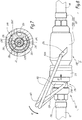
- FIG. 1 An installation 2 for handling pressurized fluid is shown in figures 1 to 11 . It comprises a terminal 4 which forms a source of pressurized fluid as well as a gun 62 which constitutes a first part of a connector 6, the complementary part 64 of which is mounted on a motor vehicle 8 which comprises an on-board tank 82 for storing the fuel. fluid under pressure and which can be coupled to the gun 62.
- a pipe 9 connects the terminal 4 to the gun 62.
- a safety circuit breaker 10 is interposed along the pipe 9 and divides the latter between a first upstream section 92, which extends between terminal 4 and circuit breaker 10, and a second downstream section 94, which extends between this circuit breaker 10 and gun 62.
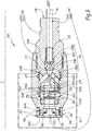
- the circuit breaker 10 comprises a male element 100 and a female element 200.
- the male element 100 extends along a longitudinal axis X100 and comprises a tubular body 102 composed of a rear part 102A and a front part 102B.
- the front of an element of circuit breaker 10 is the part of this element facing the other element of circuit breaker 10 when these elements are placed opposite one another. for their fitting.
- the front of the male element 100 is oriented to the right at the figure 1
- the front of the female element 200 is oriented to the left at the figure 3 .
- the back of an element of the fitting faces away from the front of that element.
- the body 102 is shown in one piece in the figures. It can however be composed of several parts assembled, in particular by screwing.
- the body 102 is provided with a surface 102C, which is axial, that is to say perpendicular to the axis X100.
- the part 102A is located behind the surface 102C, along the axis X100, while the part 102B is located in front of this surface, along this axis.
- a central bore 104 extends over the entire length of the male element 100, between its front face 106, which is annular in shape, flat and perpendicular to the axis X100, and its rear face 108, which is also annular, plane and perpendicular to the X100 axis.
- One end of the pipe section 92 is fixed to the rear of the male body 102 and communicates with the central bore 104.
- the front end of the central bore 104 is denoted 104B.
- a plug 110 is screwed into this end 104B and is crossed by a rod 112 which protrudes beyond the front face 106, outside the body 102.
- the stopper 110 is part of the body 102. 110B denotes the front face of the stopper 110 which is permanently crossed by the rod 112.
- the “exterior” of the male body 102 is understood to mean the volume surrounding the male body 102. Thus, the rod 112 is not entirely included in the body 102.
- the rod 112 is formed by a cylindrical body of circular section. solid, which has a first diameter ⁇ 1 at its end 112A and a second diameter ⁇ 2, strictly less than the diameter ⁇ 1, at its front end 112B.
- the rod 112 comprises a transition zone 112C arranged in the bore 104, behind the plug 110, at which the transition between the diameters ⁇ 1 and ⁇ 2 takes place.
- the body 102 is provided, along the bore 104, with a narrowed portion 102D which has an internal diameter slightly greater than the diameter ⁇ 1.
- the portion of the rod 112 located between the part 112C and its front end 112B passes through the plug 110 which is provided, for this purpose, with a central bore 110A which constitutes a sliding guide bearing for the rod 12 inside the stopper 110, along the axis X100.
- the male element 100 is provided with two radial passages 116 which connect the bore 104 to the outside of the body 102 when the male element 100 is in the uncoupled configuration. Only one of these radial passages 116 is visible on the figure 1 .
- the two radial passages are visible at the figure 6 , respectively above and below the rod 112, as well as at the figure 11 , respectively to the left and to the right of this rod.
- the bore 104 includes an enlarged portion 104C, the diameter of which is greater than that of the rest of the bore 104.
- a valve 118 is seated in the bore 104, partially at the widened portion 104C, behind the radial passages 116, and includes a solid head 118A and a cylindrical body 118B which has a stepped outer surface, with a decreasing diameter. towards the rear face 108 of the male element 100.
- Inclined passages 118C connect a central recess 118D of the cylindrical body 118B with the outer surface of this body, behind the solid head 118A.
- a spring 120 interposed, radially to the axis X100, between the cylindrical body 118B and the body 102, by default pushes the valve 118 resting against a seat 122 formed by an O-ring mounted on the male body 102, inside of the bore 104.
- the portion of the central bore 104 located behind the valve 118 is closed by the valve 118.
- the spring 120 is housed radially between the part of the cylindrical body 118B of smaller diameter and the body 102.
- the maximum diameter of the cylindrical body 118B is equal to the internal diameter of the central bore 104, behind its widened part. 104C, so that the valve 118 is guided in translation parallel to the axis X100 inside the bore 104.
- the rear end 112A of the rod 112 is disposed opposite the head 118A.
- the rod 112 is separate from the valve 118.
- the rod 112 and the valve 118 are formed by two different parts able to come into contact with one another.
- the portion of the rod 112 of diameter ⁇ 1 and the narrowed portion 102D are held axially between the solid head 118A and the transition zone 112C.
- the front part 102B of the body 102 is tubular in shape, with a circular outer surface, of variable diameter along the axis X100. More precisely, the front part 102B has two external radial surfaces of diameters ⁇ 3 and ⁇ 4 different, on either side of the radial passages 116.
- the diameter ⁇ 3 is the outside diameter of the front part 102B, behind the radial passages 116.
- the diameter ⁇ 4 is the outside diameter of the part 102B in front of the radial passages 116 , that is to say between these radial passages and the front face 106 of the male element 100, with which the seal 268 cooperates in the coupled configuration of the circuit breaker.
- 102S the external radial surface of the part 102B, which extends in front of the radial passages 116.
- a deformable protector 124 preferably made of synthetic material, is mounted on the body 102 by being engaged in an external peripheral groove 102E made on the rear part 102A of the body 102. This protector 124 extends from the groove 102E, towards the front of the element 100 and surrounds the front part 102B, over part of its axial length.
- An indexing finger 126 of the male body 102 protrudes forwardly from the surface 102C, radially between the front part 102B of the body 102 and the protector 124. This indexing finger 126 is visible to the eyes. figures 6 and 7 notably.
- a collar 130 is attached to the outer peripheral surface of the front part 102B of the body 102 by being axially blocked on this front part between a shoulder 102F of the front part and a stop segment 132 formed by a circlip engaged in a peripheral groove external 102G of the front part.
- the collar 130 is formed by a ring made of a material whose hardness is greater than that of the material used to constitute the male body 102 or, when this body is formed of several parts, the front part 102B of this body 102
- the material of the body 102 is, for its part, chosen to be compatible with the gas or gases having to pass through the male element 100, in the example of hydrogen.
- the hardness of the material of the flange 130 and the hardness of the material of the body 102 are, for example, measured according to the Vickers hardness measurement.
- the collar 130 has an external shape in double bevels which converge away from the axis X100, with a cylindrical intermediate part of diameter ⁇ 5.
- the outer surface of the collar 130 has a cylindrical outer radial surface 130A with a circular section of diameter ⁇ 5 and two front 130B and rear 130C frustoconical surfaces on either side of the surface 130A.
- Surfaces 130B and 130C are symmetrical with respect to a median plane P130 of the flange 130.
- angles ⁇ 130B and ⁇ 130C are measured outside the collar 130. These angles are chosen between 140 ° and 160 °, preferably equal to 150 °.
- the values of the angles ⁇ 130 are selected as a function of the direction on which a housing for receiving one or more locking members provided on the female element is centered, as is apparent from the explanations which follow. In the example of the figures, the angles ⁇ 130B and ⁇ 130C have the same value. As a variant, the angle ⁇ 130B is greater than the angle ⁇ 130C.
- a locking notch 134 is delimited by the outer radial peripheral surface of the front part 102B of the body 102, axially between the surface 102C and the surface 130A of the collar 130.
- This locking notch 134 has, at the level of the outer peripheral surface of the front part 102B, a diameter ⁇ 7 smaller than the diameter ⁇ 5.
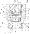
- the female element 200 comprises a body 202 which is formed of an internal part 202A and an external part 202B screwed onto the part 202A with the interposition of a seal 210. Even if this is not shown in the figures, each of the parts 202A and 202B of the body 202 can be produced by several parts assembled, in particular by screwing.
- the body 202 is centered on a longitudinal axis X200 of the female element 200 which is intended to be aligned with the axis X100 of the male element 100 during fitting and in the coupled configuration of the elements 100 and 200. When the axes X100 and X200 are aligned, together they define a press-fit axis X10 of circuit breaker 10.
- the body 202 is provided with a central bore 204 which extends generally in a direction parallel to the axis X200 and which comprises a rear portion 204A defined in the internal part 202A and a front portion or end 204B defined in the external part. 202B.
- One end of the section of pipe 94 is attached to the rear of the female body 202 and communicates with the rear portion 204A, as seen in FIG. figure 9 .
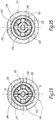
- a front portion 202C of the external part 202B is equipped with two housings 240 which pass through it, transversely to the axis X200, right through and which are each centered on a transverse axis A240.
- the two A240 axes converge in the direction of the front of the body 202.
- ⁇ 240 the angle between the axis X200, that is to say the axis X10 being fitted and in coupled configuration, and the axis A240 of a housing 240 , the angle ⁇ 240 being measured on the rear side of the housing 240.
- the value of an angle ⁇ 240 is between 60 ° and 80 °, preferably equal to 70 °.
- the two housings 240 are symmetrical with respect to the axis X200 and each receive a locking ball 242.
- the dimensions of each housing 240 transverse to the axis A240 are chosen according to the diameter of the balls 242 to be compatible with a displacement of the balls. balls transverse to axis X10 along axes A240, between an internal radial position and an external radial position.
- the housings narrow towards the inside of the body 202, that is to say in the direction of the axis X200, in order to prevent the balls 242 from falling into the front portion 204B of the bore 204.
- angles ⁇ 130B, ⁇ 130C and ⁇ 240 are chosen as a function of each other. More precisely, it is preferable for a movement of the balls 242 without jamming in the housing 240 on uncoupling that: ⁇ 240 + ⁇ 130 VS ⁇ 200 °
- An elastically deformable ring 246 is received in an outer groove 248 formed on the outer radial surface of the front portion 202C of the body 202.
- the groove 248 defines a front edge and a rear edge which extend in the direction radial to the axis. X200. All the housings 240 open into the groove 248.
- the elastically deformable ring 246 surrounds all the housings 240 and is in contact with all the balls 242 on which it exerts a centripetal force E1 directed towards the axis X200.
- the internal diameter of the ring 246, at rest and not mounted on the female body 202 is less than the largest diameter of an imaginary cylindrical surface centered on the axis X200 and tangent to the balls 242 in the internal radial position.
- this ring 246 is made of steel.
- the ring 246 has a rectangular section in a plane radial to the axis X200.
- the groove 248 extends over only a part of the periphery of the portion 202C and the ring 246 is a split ring, which extends, around the axis X200, over an angular sector whose angle ⁇ 246 is adapted the position of the housings 240 and the balls 242, on the one hand, and the geometry of the groove 248, on the other hand.
- the value of the angle ⁇ 246 in the retracted configuration of the ring 246 mounted around the balls 242 can be chosen between 210 ° and 240 °, preferably equal at 225 °.
- the angle ⁇ 246 is chosen greater than the angle of a sector angular covering all of the housings 240 and so that the ring 246 in an enlarged configuration covers all of the housings 240.
- outer groove 248 extends only over a part of the circumference of the front portion 202C makes it possible to block the ring 246 in rotation around the axis X200 and to ensure contact between this ring 246 and the balls. 242 in all configurations of use of circuit breaker 10.
- the width l248 of the groove 248 measured parallel to the X200 axis between the leading edge and the trailing edge is equal to or slightly greater, within 10%, than the width l246 of the bushing 246 measured parallel to the X200 axis.
- the groove 248 makes it possible to ensure effective guiding of the movement of the ring 246, in a direction radial to the axis X200, and a retention of the ring 246 in the female body 202 along the axis X200, in the uncoupled configuration of the 'female element, in the coupled configuration of the male and female elements, and when the ring 246 widens or retracts radially to the axis X200, as explained below.
- ⁇ 6 the smallest diameter of an imaginary cylindrical surface centered on the axis X200 and tangent to the balls 242 in the uncoupled configuration of the male 100 and female 200 elements, that is to say when the balls 242 are pushed back by the elastically deformable ring 246 in the direction of the axis X200, in the internal radial position.
- the diameter ⁇ 6 is smaller than the diameter ⁇ 5, by at least 10%.
- the maximum external diameter ⁇ 5 of the collar 130 of the male element 100 is greater than the diameter of the imaginary cylindrical surface defined between the two locking balls 242 in the internal radial position, with the elastically deformable ring 246 in a retracted configuration where it pushes the locking balls 242 towards the X200 axis.
- the diameter ⁇ 6 is strictly greater than the diameters ⁇ 3 and ⁇ 4.
- the external diameter ⁇ 7 of the front part 102B of the body 102 at the level of the notch 134 is substantially equal to the diameter ⁇ 6.
- the body 202 includes a stopper ring 250.
- the stopper ring 250 is interposed axially, along the axis X200, between the front portion 202C of the outer part 202B and a front portion 202D of the inner part 202A of the body 202
- the internal part 202A is screwed into the central bore of the internal part 202B, while the stop ring 250 is immobilized axially between a shoulder 202E of the external part 202B and a leading edge 202F of the internal portion 202A.
- This stop ring 250 is provided with four radial passages 256, distributed at 90 ° around the axis X200.
- the internal volume of the stop ring 250 is a reception volume Va of the body male 102.
- the radial passages 256 communicate with the outside of the female element 200 at the reception volume Va when the female element 200 is in the uncoupled configuration.
- An annular space 204D is formed around the stopper ring 250 and the front portion 202D of the internal part 202A, inside the external part 202B of the body 202.
- This annular space 204D is in communication with two inclined passages 204E. formed in the rear part 202B and which connect the annular space 204D to the rear portion 204A of the central bore 204 in which is disposed a valve 218.
- the volumes 204D and 204E form part of the central bore 204.
- the valve 218 comprises, like valve 118, a solid head 218A, a cylindrical and stepped body 218B, inclined passages 218C and a central recess 218D.
- a spring 220 defaults to pushing the valve 218 against a seat 222 formed in the internal part 202A of the body 202.
- the valve 218 is disposed in an enlarged part 204C of the bore 204, of larger diameter. important than the rear portion 204A of this bore.
- the radial passages 256, the annular space 204D, the inclined passages 204E and the inclined passages 218C of the valve 218 and the rear portion 204A communicate when the valve 218 is offset from its seat 222 and form an internal conduit for the circulation of fluid through it. the female body 202.
- a first sealing O-ring 266 is housed in the front portion 204B of the central bore 204, in the outer portion 202B of the body 202, axially between the front face 206 and the stop ring 250.
- a second O-ring 268 d The seal is disposed on the other side of the stop ring 250, that is to say axially between this ring 250 and the valve 218.
- the seals 266 and 268 are identical. They are made of elastomer and denote ⁇ 8 their internal diameter and ⁇ 9 their toroid diameter, these diameters being measured in the uncoupled configuration of the male and female elements 100 and 200, that is to say when the O-rings of sealing 266 and 268 are not constrained by the front part 102B of the body 102.
- the sealing gaskets 266 and 268 are uncovered, that is to say accessible radially from the inside of the body 202 from the reception volume Va.
- the sealing O-ring 266 is received in a housing 270 formed inside the external part 202B of the body 202, defined axially between a shoulder 202G of this body, a front face 250B of the stop ring 250 and delimited by an external radial bottom formed on an internal radial surface of the front part 202B of the body 202.
- This housing 270 is in the form of an internal peripheral groove centered on the axis X200 and P270 denotes its radial depth, that is to say the distance between its external radial bottom and its internal radial edge.
- This depth P270 has a value between 75 and 88% of the diameter ⁇ 9, preferably equal to 85% of this diameter.
- the second sealing O-ring 268 is disposed in a housing 272, in the form of an internal peripheral groove centered on the axis X200, defined axially between a shoulder 202H of the internal part 202A of the body 202 and a rear face 250A. of the stop ring 250 and delimited by an external radial bottom formed on an internal radial surface of the rear part 202A of the body 202.
- P272 denotes the radial depth of this housing 272, defined as the depth P270.
- the depth P272 has a value between 75 and 88% of the diameter ⁇ 9, preferably equal to 85% of this diameter.
- the ratio ⁇ 8 / ⁇ 9 is selected with a value less than 2.5, preferably less than 2.2, more preferably of the order of 2.14 in the uncoupled configuration of the male 100 and female 200 elements.
- Each of the first and second seals 266 and 268 preferably has a hardness greater than 85 Shore, preferably greater than 90 Shore, it being specified that these seals can be made of polyurethane.
- the interior portion 202A of the body 202 is provided with an axial surface 274, in the form of a disc, perpendicular to the axis X200 and centered thereon, disposed behind the radial passages 256 and the seals 266 and 268
- the seal 268 is closest to the surface 274.
- This surface 274 is intended to receive a support at the front end 112B of the rod 112 being fitted and in the coupled configuration of the male 100 and female 200 elements.
- d1 the axial distance, measured parallel to the axis X200 between, on the one hand, the surface 274 and, on the other hand, a plane P268 median to the joint 268, perpendicular to the axis X200 and passing through the center of this seal when it rests against the shoulder 202H, in the uncoupled configuration of the male 100 and female 200 elements.
- the body 202 comprises a longitudinal groove 226 for receiving the indexing finger 126.
- the groove 226 cooperates with the indexing finger 126 for the rotational indexing of the bodies 102 and 202 around the body. press-fit axis X10, when the male 100 and female 200 elements are being fitted or in coupled configuration.
- the axes X100 and X200 are aligned on the fitting axis X10 and the body 102 and 202 around this fitting axis X10 so as to have the indexing finger 126 facing the indexing groove 226.
- the male 102 and female body 202 are then brought together in axial translation, along the 'X10 axis. This has the effect of introducing the front portion 102B of the body 102 into the front portion 204B of the bore 204. As a result of this movement, the outer peripheral surface of the front portion 102B comes into contact with the first sealing O-ring. 266, then the second sealing O-ring 268.
- a so-called radial seal is thus obtained between the male 102 and female 202 body, between an internal radial surface of the body 202 constituting the bottom of the housing 270 and an external radial surface of the body 102 , via the seal 266, and between an internal radial surface of the body 202 constituting the bottom of the housing 272 and the external radial surface 102S of the body 102, via the seal 268.
- the collar 130 arrives opposite, along the axis X10, the balls 242.
- the collar 130 radially pushes the balls 242 back, in a centrifugal direction to the axis X10, against the force E1, which is possible given the elastically deformable nature of the ring 246 which then deforms so centrifugal at axis X10.
- the balls 242 are thus pushed back, while remaining engaged in the housings 240, along the axis A240, in an external radial position, where the balls 242 protrude into the groove 248, to temporarily increase the value of the diameter ⁇ 6 and freeing a sufficient passage for the male body 102 with the collar 130 in the female body 202.
- the balls 242 act radially on the ring 246, by direct contact, and the elastically deformable ring 246 adopts a radially widened or expanded configuration , wherein the inner diameter of the ring 246 increases relative to the inner diameter of the ring 246 in the uncoupled configuration of the female member 200, allowing centrifugal movement of the locking balls 242 along the axis A240.
- the ring is deformed in direct contact with the balls 242 in all the configurations of the female element 200.
- the axial distance d1 is greater than the axial distance d2.
- an external peripheral groove 176 is provided on the male body 102, while the female body 202 is provided with two inclined grooves 276 of which only one is visible at the figure 8 but which are both visible in section at the figure 6 .
- a tilting force tool 300 around the ends 302A in the direction of arrow F1 at the figure 8 , it is possible to exert on the side 176B of the groove 176 an axial force E2 directed towards the body 202 of the female element 200.
- the tool 300 therefore makes it possible to multiply the force exerted by the operator on the tool 300 in the effort of fitting the male 100 and female 200 elements into one another.
- the use of the tool 300 is not compulsory. This tool can be omitted if the operator is able to exert a fitting force sufficient to push the balls 242 radially into the housings 240, against the elastic force E1 exerted by the ring 246, and to move the rod 112 towards the inside of the body 202, until unstick valve 118 from seat 122.
- grooves and grooves 176 and 276 can be omitted.
- the protector 124 comes into contact with the external surface of the part 202B of the body 202, widening by means of an elastic deformation.
- the protector 124 isolates the groove 248 and the elastically deformable ring 246 from the outside, which prevents the pollution of these parts by external elements and guarantees correct operation of the circuit breaker 10 in this regard.
- a radial clearance J1 of the order of 1mm is provided between the ring 246 in the enlarged configuration and the protector 124, which prevents the protector 124 from opposing the elastic centrifugal deformation of the ring 246 when the locking balls 242 move towards their external radial position, when passing the obstacle formed by the collar 130.
- the pressurized fluid can flow through the bore 104, passing through the passages 118C of the valve 118 and then circulating inside the bore. 'bore 104, around the rod 112, until it passes through the radial passages 116 which are partly aligned, radially to the axis X10, with two of the four radial passages 256, this radial alignment being ensured by the cooperation of the finger d 'indexing 126 with the indexing groove 226
- the bore 104 behind the stopper 110, the passages 118C, the radial passages 116 form an internal duct for the circulation of fluid in the male body 102.
- the pressurized fluid can then s' flow from the radial passages 116 in an annular space 402 defined between the male body 102 and the female body 202, this annular space 402 being closed axially by the seals 266 and 268 arranged on either side of the radial passages 116 and 256 along the X10 axis.
- the seal 266 is disposed on one side of the radial passages 116 and 256 along the axis X10
- the seal 268 is disposed on the other side of the radial passages. 116 and 256 along the X10 axis.
- the pressurized fluid can then flow to the radial passages 256, then into the annular space 204D and into the inclined passages 204E.
- the pressure of the fluid arriving through the inclined passages 204E makes it possible to push the valve 218 against the force exerted by the spring 220, which frees the passage towards the rear of the bore 204.
- the front face 206 of the body 202 constitutes an axial abutment surface to the male body 102 in the fitting direction, the front face 206 cooperating with the surface 102C of the male body 102, while the balls 242 do not have no axial stop against the body 102 in the fitting direction.
- the forces tending to bring the male 102 and female 202 body together in the coupled configuration are not taken in by the balls 242 and do not stress the elastically deformable ring 246.
- the pressurized fluid can flow through the circuit breaker 10, from the pipe section 92 to the pipe section 94, as represented by the flow arrows E at the figure 9 .
- the male body 90 is balanced, in terms of pressure, vis-à-vis the outside of the circuit breaker, despite the high pressure of the fluid in transit.
- the seal between the rod 112 and the male body 102 is produced at the level of the contact of a third sealing O-ring 167, this third sealing O-ring being mounted axially between the constricted part 102D and the plug. 110.
- the seal is also obtained at the level of the contact of the seals 266 and 268 with the outer peripheral surface of the front part 102B of the body 102.
- the rod 112, the plug 110 and the third seal 167 close the central bore 104 on the front of the male body 102 in the direction of the longitudinal axis X1. In other words, the rod 112, the plug 110 and the third seal 167 close off the front axial end 104B of the central bore 104.
- the flange 130 fails to deform the ring 246 and the balls 242 remain engaged in the locking notch 134 and cut it. -circuit resists this effort.
- this tearing force E3 has the effect of sliding or rolling the balls 242 against the frustoconical surface 130C of the flange 130 oriented towards the surface 102C, which has the effect of pushing the balls 242 back in a direction centrifugal to the axis X10, inside housing 240 along axis A240.
- the ring 246 deforms elastically, radially outwards, that is to say in a centrifugal direction with respect to the axis X10, to accommodate this displacement of the balls 242 from their first radial position inside the axis.
- the pull-out force E3 makes it possible to separate the male and female elements 100 and 200 from one another, without breaking the pipe sections 92 and 94.
- the bearing surface 274 gradually moves away from the front face 106, which allows the rod 112 to slide to the right of the figure 9 , by being pushed back by the valve 118 subjected to the action of the spring 120.
- the valve of the male element is gradually closed, which cuts off the valve. circulation of fluid within the installation 2.
- the valve 218 closes again under the effect of the spring 220.
- a non-return valve is integrated into the pipe section 94 or the gun 162, in order to prevent a rise of pressurized fluid from the reservoir 82.
- the portion of the pipe 9 between this non-return valve and the valve 218 of the female element 200 is purged through an exhaust duct 278 which connects the widened part 204C of the bore 204 with a vent 280 formed in the internal part 202A of the body 202, this vent 280 connecting the exhaust duct 278 to the surface 274 which communicates with the exterior of the body 202 when the female element is uncoupled and to a rear volume V202 of the body 202 in communication with the outside of the body 202.
- This vent also makes it possible to evacuate the air trapped between the surfaces 106 and 274 during the fitting of the male 100 and female 200 elements into one another .
- the elastically deformable ring 246 When an operator wishes to disconnect the male 100 and female 200 elements of the circuit breaker 10, in particular for a maintenance operation, he must exert on the male and female bodies 102 and 202 a sufficient separation force, parallel to the force. E3 mentioned above, to allow the locking balls 242 to expand radially, centrifugally with respect to the fitting axis X10, the elastically deformable ring 246. In other words, the uncoupling initiated by an operator has take place in a sequence comparable to the emergency disconnection envisaged above. When the male element 100 is out of the female element 200, the ring 246 pushes the balls 242 back to the internal radial position.
- a tool can be provided which engages in an external groove of the female body and in an external groove of the male body, in particular the volumes 176 and 276, in order to multiply tenfold. force exerted in this case by the operator for the relative separation of the two male body 102 and female 202 along the axis X10.
- the female element 200 which is connected to terminal 4, while the male element 100 is connected to the gun 62.
- the upstream 92 and downstream 94 pipe sections are therefore respectively connected to the The female element 200 and the male element 100.
- the bore 204 passes through the internal part 202A of the body 202 right through along the axis X200.
- the body 202 of the female element 200 defines a volume Va for accommodating the body 102 of the male element in the coupled configuration of these elements.
- the valve 218 of the female member is one piece with a stem 212 which passes through the internal portion 202A of the body 202 and the axial surface 274, and the forward end 212B of the stem 212 protrudes beyond the axial surface 274 of the body.
- body 202 defined as in the first embodiment, in uncoupled configuration and in coupled configuration of the circuit breaker.
- a seal 267 is mounted in the internal part 202A of the body 202, between two narrowed parts of this body and produces a sealing surface around a portion of the rod 212, the diameter of which is denoted ⁇ 2 '.
- the front part 102B of the body 102 is of circular section and has two diameters ⁇ 3 'and ⁇ 4', respectively behind and in front of two coaxial radial passages 116 which connect a central bore 104 of the male element 100 to the 'exterior thereof in uncoupled configuration.
- the front end of the central bore 104 is closed off on the front of the male body 102, by a solid head 102H of the male body 102.
- a first seal 266 and a second seal 268 are in sealed bearing against the portions of the front part 102B of the body 102 of diameter ⁇ 3 ', respectively ⁇ 4'.
- the body 102 of the connecting element 100 is balanced with respect to the outside of the circuit breaker 10 despite the pressure of the fluid passing through the body 102.
- the collar 130 is not constituted by an attached part but by a portion of the front part 102B of the body 102 which is integral with this front part.
- the flange 130 of this second embodiment comprises a cylindrical outer peripheral surface 130A with a circular section as well as two frustoconical surfaces 130B and 130C.
- the locking members consist of four locking segments 242 regularly distributed around the axis X10 and subjected to an elastic and centripetal force E1 exerted by an elastically deformable ring 246 which extends over 360 ° around a front portion 202C of the external part 202B of the body 202.
- the housings 240 of the locking segments 242 in the body 202 extend in a direction radial to the longitudinal axis X2.
- the locking segments 242 In section in a radial plane to the press-fit axis X10, the locking segments 242 have a polygonal section with an internal radial edge 242A parallel to the axis X10 and two rear inclined edges 242B and front 242C respectively parallel or nearly parallel to the surfaces 130B and 130C. This facilitates the sliding of the segments 242 on the collar, respectively during the fitting and during the uncoupling of the male 100 and female 200 elements.
- the ring 246 is continuous, that is to say it is annular and surrounds the segments 242 over 360 ° around the axes X200 and X10.
- the continuous geometry of the ring 246 requires it to be mounted from the front of the female body 202.
- a stop segment 232 is used which limits the axial displacements. of the ring 246 relative to the body 202, in cooperation with a shoulder 202l of the body 202.
- the stop segment 232 and the shoulder 202l constitute the two axial edges of a groove 248 formed at the level of the outer radial surface of the body 202 and which axially retains the ring 246 relative to the female body 202 between the enlarged configuration and the retracted configuration of the ring 246.
- the front face 106 of the body of the male element 100 which is disc-shaped perpendicular to and centered on the fitting axis X10, comes into contact with the front end 212B of the rod 212 after the seal is effective between the male 102 and female 202 bodies, at the seals 266 and 268.
- the front face 106 then exerts a force which pushes the valve 218 against an elastic force exerted by a spring 220.
- the pressure of the fluid arriving through the radial passages 116 is sufficient to push the valve 118 against an elastic force exerted by a spring 120. This establishes the flow of fluid within the circuit breaker 10, as shown by the flow arrows E at the bottom. figure 14 .
- the operation of the circuit breaker 10 of this second embodiment is comparable to that of the first embodiment.
- the collar 130 pushes the locking segments 242 against the elastic force E1 exerted by the elastically deformable ring 246, by deforming the ring 246 centrifugally on the axis X10, as shown in figures 12 and 13 , up to its extended configuration. Locking segments 242 are then pushed back by the ring 246 into the locking notch 134.
- the withdrawal force causes the locking segments 242 to be moved axially, up to around the flange 130 by deforming the ring 246 which then widens radially centrifugally with respect to the press-fit axis X10, until the locking segments 242 come out of the locking notch 234 and thus free the body 102 from the male element 100 vis-à-vis the body 202 of the female element 202.
- the front face 206 of the body 202 bears against an axial surface 102C of the body 102, defined as in the first embodiment, without the front face 106 of the male element 100 bears against the surface 274. It There therefore remains an axial clearance J2 between the surfaces 106 and 274 in the coupled configuration.
- the actuating rod 212 is integral with the valve 218. Such could also be the case for the actuating rod 112 and the valve 118 of the first embodiment.
- the elastic radial deformation of the elastic ring 246 between the enlarged configuration in contact with the locking members in the internal radial position and the retracted configuration in contact with the locking members in the external radial position allows, on the one hand, an automatic locking of the male and female elements of the circuit breaker 10, thanks to an essentially axial operation during fitting, and automatic unlocking of these elements, whether this locking is emergency or voluntary, also thanks to an essentially axial operation.
- the circuit breaker 10 is compact, in particular in a direction parallel to the axis X10.
- the type of locking obtained is compatible with the high pressures used in pressurized fluid handling installations since the male body 102 has two sealing sections S3 and S4, on either side of the radial passages for the fluid, 116 and 256, which makes it possible to reduce the effects of the pressure on the male body 102.
- the male body 102 through which the pressurized fluid passes can be balanced, as can be seen from the relationship between the sealing sections S2, S3 and S4 mentioned in equations 6 and 8.
- the seal is taken at the level of the first and second seals 266 and 268 before the opening of the valve 118 and before the locking of the male and female elements one in the other.
- the pressure of the fluid does not impact the locking force which is compatible with an axial maneuver.
- the male body 102 is balanced and the pressure does not exert any unlocking force on the locking members 242.
- the uncoupling force is independent of the pressure of the fluid passing through the circuit breaker 10, which makes the operation of this circuit breaker more reliable.
- the protector 124 protects the elastic ring 248 in the mated configuration, which limits the risks of dust interfering with the radial deformation of the elastic ring 246 and the operation of the circuit breaker.
- the actuating rod 112 or 212 advantageously replaces the EP-A-0 900 966 .
- the operation of the circuit breaker is made more reliable because a stacking of tolerances or a jamming of the valve 118 is avoided.
- the front end 112B or 212B of the actuating rod remains permanently outside the body 102 or 202.
- the front end 112B or 212B remains permanently on the body. front of an axial surface of the body 102 formed by the front face 110B of the plug 110 in the first embodiment or by the axial surface 274 of the body 202 in the second embodiment, axial surface that the rod passes through, which avoids to interfere with the radial centering of the male body 102 in the two seals 266 and 268.
- the split ring 246 allows easy mounting of the balls 242 in their respective housings 240, as well as easy mounting of this split ring on the female body 202.
- the split ring can be chosen from a material harder than a simple elastic ring, its life can be increased.
- the balls 242 have a geometry which limits the risks of jamming, which guarantees correct operation of the circuit breaker.
- the inclined nature of the housings 240 of this first embodiment makes it possible to differentiate the separation force E3, which results in an emergency uncoupling, from the locking force.
- the locking force may be less than the emergency uncoupling force and the unlocking force.
- the balls are only in contact with the collar 130 during coupling / uncoupling maneuvers, which prevents the sealing surfaces provided on the male body 102 from being damaged by the friction of the balls 242.
- the part of the circuit breaker 10 which is equipped with the actuating rod namely the male element 100 in the first embodiment and the female element 200 in the second embodiment, is preferably placed on the side of. the source of pressurized fluid, that is to say on the upstream side with respect to the direction of circulation of the pressurized fluid because, as this rod projects out of the body that it passes through, this rod is relatively fragile and could be altered if this element was dragged on the ground by a vehicle.
- the sealing surfaces on the body 102, unprotected are not dragged on the ground by a vehicle during emergency disconnection and the sensitive surfaces of the female element 200 are protected during disconnection. because they are rather located inside the body 202.
- the passages 116 and 256 described as extending radially may be transverse to the longitudinal axis X100, respectively X200.
Landscapes
- Engineering & Computer Science (AREA)
- General Engineering & Computer Science (AREA)
- Mechanical Engineering (AREA)
- Life Sciences & Earth Sciences (AREA)
- Sustainable Development (AREA)
- Sustainable Energy (AREA)
- Chemical & Material Sciences (AREA)
- Combustion & Propulsion (AREA)
- Transportation (AREA)
- Quick-Acting Or Multi-Walled Pipe Joints (AREA)
Claims (15)
- Unterbrechungsvorrichtung (10) für den Anschluss von zwei Abschnitten (92, 94) einer Rohrleitung (9) einer Anlage (2) zur Förderung von unter Druck stehendem Fluid, wobei diese Unterbrechungsvorrichtung ein Einsteckelement (100) und ein Aufnahmeelement (200) umfasst, die dazu bestimmt sind, gemäß einer Eingreifachse (X10) ineinandergesteckt zu werden,wobei das Einsteckelement einen Einsteckkörper (102) umfasst, der einen ersten Innenkanal (104) für eine unter Druck stehende Fluidströmung definiert und mit- mindestens einem Element (110, 112, 167; 102H) zum Verschließen eines vorderen Endes (104B) des ersten Innenkanals gemäß der Eingreifachse (X10),- mindestens einem ersten Durchgang (116), der radial zur Eingreifachse (X10) verläuft und den ersten Innenkanal (104) im entkuppelten Zustand der Einsteck- und Aufnahmeelemente der Unterbrechungsvorrichtung mit dem Außenraum des Einsteckkörpers verbindet,- einem Ventil (118), das in dem ersten Innenkanal beweglich ist, und- einer Verriegelungsausnehmung (134), die am Einsteckkörper angeordnet ist, versehen ist,wobei das Aufnahmeelement einen Aufnahmekörper (202) umfasst, der einen zweiten unter Druck stehenden Fluidströmungsinnenkanal (204A) definiert und mit- mindestens einem zweiten Durchgang (256), der radial zur Eingreifachse (X10) verläuft und die zweite Innenleitung (204A) mit einem Volumen (Va) zu Aufnahme des Einstecckörpers (102) im Aufnahmekörper verbindet,- einem Ventil (218), das in dem zweiten Innenkanal beweglich ist,- einer Mehrzahl von Verriegelungselementen (242), die quer zur Einführachse in Aufnahmeräumen (240) des Aufnahmekörpers zwischen einer ersten radialen Position, in der die Verriegelungselemente in die Verriegelungsausnehmung (134) eingreifen, um den Einsteckkörper (102) mit dem Aufnahmekörper (202) in der gekuppelten Konfiguration der Einsteck- (100) und Aufnahmeelemente (200) der Unterbrechungsvorrichtung (10) axial zu verriegeln, und einer zweiten radialen Position, in der die Verriegelungselemente das Durchführen des Einsteckkörpers in den Aufnahmekörper freigeben, beweglich sind, versehen ist,wobei in der gekuppelten Konfiguration der erste und der zweite radiale Durchgang (116, 256) in Verbindung stehen, wobei eine erste Dichtung (266) und eine zweite Dichtung (268) entlang der Einführachse (X10) auf beiden Seiten des ersten und des zweiten radialen Durchgangs (116, 256) angeordnet sind und radial mit den Einsteckund Aufnahmekörpern zusammenwirken,dadurch gekennzeichnet, dass ein elastischer Rückstellring (246) auf dem Aufnahmekörper (202) angebracht ist und die Verriegelungselemente (242) umgibt, wobei der Ring ausgebildet ist, die Verriegelungselemente in der gekuppelten Konfiguration elastisch in ihre erste radiale Position zurückzustellen und von den Verriegelungselementen bei ihrer Bewegung aus ihrer ersten radialen Position in ihre zweite radiale Position radial und elastisch verformt zu werden.
- Unterbrechungsvorrichtung nach Anspruch 1, dadurch gekennzeichnet, dass sie einen Stab (112; 212) zur Betätigung eines ersten Ventils (118; 218) von dem Ventil (118) des Einsteckelements und dem Ventil (218) des Aufnahmeelements umfasst, wobei dieser Stab einen ersten Körper durchgreift, der von dem Einsteckkörper (102) oder dem Aufnahmekörper (202) gebildet ist und das erste Ventil aufnimmt, wobei eine dritte Dichtung (167; 267) zwischen dem ersten Körper und dem Stab angeordnet ist, und verschiebbar in dem ersten Körper in einer Richtung parallel zu der Einführachse (X10) angeordnet ist, und dass der zweite Körper (202, 102) von dem Einsteckkörper und dem Aufnahmekörper eine Auflagefläche (274, 106) für den Stab definiert, die ausgebildet ist, den Stab während des Ineinandergreifens der Einsteck-(100) und Aufnahme-(200)elemente in Richtung der Rückseite des ersten Körpers zu drücken, um das erste Ventil von einer geschlossenen Position in eine offene Position des Innenkanals des ersten Körpers zu bewegen.
- Unterbrechungsvorrichtung nach Anspruch 2, dadurch gekennzeichnet, dass der Stab (112) von dem ersten Ventil (118), das er betätigt, getrennt ist.
- Unterbrechungsvorrichtung nach einem der Ansprüche 2 oder 3, dadurch gekennzeichnet, dass sich das vordere Ende (112B, 212B) des Stabs (112, 212) in der entkuppelten und gekuppelten Konfiguration der Unterbrechungsvorrichtung gemäß der Einführachse (X10) nach vorne über eine Fläche (106, 274) des ersten Körpers hinaus erstreckt, die der Stab (112) durchgreift.
- Unterbrechungsvorrichtung nach einem der Ansprüche 2 bis 4, dadurch gekennzeichnet, dass in der gekuppelten Konfiguration die erste Dichtung (266) weiter vorne im Aufnahmekörper (202) angeordnet ist als die zweite Dichtung (268), während ein Dichtungsabschnitt (S4) zwischen der zweiten Dichtung (268) und dem Einsteckkörper (102) gleich der Summe eines Dichtungsabschnitts (S3) zwischen der ersten Dichtung (266) und dem Einsteckkörper und eines Dichtungsabschnitts (S2) zwischen der dritten Dichtung (167; 267) und dem Stab (112; 212) ist.
- Unterbrechungsvorrichtung nach einem der Ansprüche 2 bis 5, dadurch gekennzeichnet, dass die erste Dichtung (266) und die zweite Dichtung (68) jeweils in einer inneren Umfangsnut (270, 272) des Aufnahmekörpers aufgenommen sind und dass der Stab (112) das Ventil (118) des Einsteckelementes (100) betätigt.
- Unterbrechungsvorrichtung nach Anspruch 6, dadurch gekennzeichnet, dass ein erster Abstand (d1), gemessen in axialer Richtung zwischen der Auflagefläche (274) und der dieser Fläche am nächsten liegenden Dichtung (268) unter der ersten Dichtung (266) und der zweiten Dichtung (268), größer ist als ein zweiter Abstand (d2), gemessen in axialer Richtung zwischen dem vorderen Ende (102l) der radialen Außenfläche (102S) des Einsteckkörpers (102) und dem vorderen Ende (112B) des Stabs (112), wenn der Stab in Kontakt mit dem Ventil (118) des Einsteckelements (100) ist, ohne es von seinem Sitz (122) zu trennen.
- Unterbrechungsvorrichtung nach einem der vorhergehenden Ansprüche, dadurch gekennzeichnet, dass die erste Dichtung (266) und die zweite Dichtung (268) O-Ringe sind und dass für jede der ersten und zweiten Dichtungen das Verhältnis zwischen dem Innendurchmesser (Φ8) dieser Dichtung in der entkuppelten Konfiguration der Unterbrechungsvorrichtung einerseits und dem Torusdurchmesser (Φ9) dieser Dichtung andererseits kleiner als 2,5, vorzugsweise 2,2 ist.
- Unterbrechungsvorrichtung nach einem der vorhergehenden Ansprüche, dadurch gekennzeichnet, dass zwischen einer ersten Konfiguration (Fig. 2; Fig. 12) des elastischen Rückstellrings (246) in Kontakt mit den Verriegelungselementen (242) in ihrer ersten radialen Position und einer zweiten Konfiguration (Fig. 3; Fig. 10) des elastischen Rückstellrings (246) in Kontakt mit den Verriegelungselementen in ihrer zweiten radialen Position, der elastische Rückstellring (246) axial in einer Nut (248) gehalten wird, die an der radialen Außenfläche des Aufnahmekörpers (202) vorgesehen und durch zwei axiale Ränder begrenzt ist.
- Unterbrechungsvorrichtung nach einem der vorhergehenden Ansprüche, dadurch gekennzeichnet, dass der elastische Rückstellring (246) ein Spaltring ist, der auf zwei Verriegelungselemente (242) wirkt, die in zwei zur Einführachse (X10) symmetrischen Aufnahmeräumen (240) beweglich sind.
- Unterbrechungsvorrichtung nach einem der vorhergehenden Ansprüche, dadurch gekennzeichnet, dass die Verriegelungselemente Verriegelungskugeln (242) sind.
- Unterbrechungsvorrichtung nach einem der vorhergehenden Ansprüche, dadurch gekennzeichnet, dass die Verriegelungselemente (242) in Aufnahmeräumen (240) aufgenommen sind, die jeweils auf eine Achse (A240) quer zur Einführachse (X10) zentriert sind, dass die Querachsen (A240) der Aufnahmeräume (240) in Richtung der Vorderseite des Aufnahmekörpers (202) konvergieren und dass ein Winkel (α240) zwischen der Einführachse (X10) und der Querachse (A240) jedes Aufnahmeraums (240), gemessen an der Rückseite des Aufnahmeraums (240), zwischen 60° und 80° und vorzugsweise gleich 70° beträgt.
- Unterbrechungsvorrichtung nach einem der vorhergehenden Ansprüche, dadurch gekennzeichnet, dass die Verriegelungsausnehmung (134) entlang der Einführachse (X10) auf der Seite der Vorderseite (106) des Einsteckelements (100) durch eine erste kegelstumpfförmige Fläche (130C) eines Kragens (130) begrenzt ist, und dass der Neigungswinkel (γ130C) der ersten kegelstumpfförmigen Fläche (130C) in Bezug auf die Einführachse (X10), gemessen vom Kragen weg, zwischen 140° und 160° und vorzugsweise 150° beträgt.
- Unterbrechungsvorrichtung nach einem der vorhergehenden Ansprüche, dadurch gekennzeichnet, dass in der gekuppelten Konfiguration der Einsteck-(100) und Aufnahme-(200)elemente der Aufnahmekörper (202) eine Fläche (206) zum axialen Anschlag an den Einsteckkörper (102) in der Einführrichtung bildet.
- Anlage zur Förderung von unter Druck stehendem Fluid, die eine Quelle (4) für unter Druck stehendes Fluid und einen ersten Teil (62) einer Kupplung (6) umfasst, die dazu bestimmt ist, mit einem zweiten Teil (64) der Kupplung verbunden zu werden, der mit einem Volumen (82) zur Speicherung oder Verwendung des Fluids verbunden ist, wobei der erste Teil (62) der Kupplung über eine Leitung (9) mit der Quelle in Fluidverbindung steht, dadurch gekennzeichnet, dass eine Unterbrechungsvorrichtung (10) nach einem der vorhergehenden Ansprüche über einen ersten Abschnitt (92) der Leitung mit der Quelle (4) und über einen zweiten Abschnitt (94) der Leitung mit dem ersten Teil (62) der Kupplung (6) in Fluidverbindung steht.
Applications Claiming Priority (1)
| Application Number | Priority Date | Filing Date | Title |
|---|---|---|---|
| FR1758573A FR3071301B1 (fr) | 2017-09-15 | 2017-09-15 | Coupe-circuit et installation de manutention de fluide sous pression comprenant un tel coupe-circuit |
Publications (2)
| Publication Number | Publication Date |
|---|---|
| EP3457016A1 EP3457016A1 (de) | 2019-03-20 |
| EP3457016B1 true EP3457016B1 (de) | 2021-11-10 |
Family
ID=60627782
Family Applications (1)
| Application Number | Title | Priority Date | Filing Date |
|---|---|---|---|
| EP18194412.5A Active EP3457016B1 (de) | 2017-09-15 | 2018-09-14 | Sicherheitsschalter und anlage zur handhabung eines fluids unter druck, die einen solchen sicherheitsschalter umfasst |
Country Status (5)
| Country | Link |
|---|---|
| US (1) | US10724667B2 (de) |
| EP (1) | EP3457016B1 (de) |
| CN (1) | CN109555925B (de) |
| CA (1) | CA3017049A1 (de) |
| FR (1) | FR3071301B1 (de) |
Families Citing this family (4)
| Publication number | Priority date | Publication date | Assignee | Title |
|---|---|---|---|---|
| PT3963246T (pt) | 2019-05-03 | 2023-03-31 | Elaflex Hiby Gmbh & Co Kg | Acoplamento breakaway com proteção contra torção |
| FR3096109B1 (fr) * | 2019-05-14 | 2021-05-28 | Staubli Sa Ets | Elément femelle et raccord fluidique |
| DK3767153T3 (da) * | 2019-07-16 | 2021-12-06 | Oasis Eng Ltd | Påfyldningsmundstykke til gasformigt eller fortættet brændstof med forhaling mellem kobling og aktivering |
| CN111853404B (zh) * | 2020-08-01 | 2023-05-09 | 河南斯凯特汽车管路有限公司 | 一种管路连接接头 |
Family Cites Families (12)
| Publication number | Priority date | Publication date | Assignee | Title |
|---|---|---|---|---|
| US3130749A (en) * | 1960-01-27 | 1964-04-28 | Deere & Co | Fluid line coupling |
| US3715099A (en) * | 1971-06-02 | 1973-02-06 | Crawford Fitting Co | Valved quick-disconnect coupling |
| US4398561A (en) * | 1981-03-27 | 1983-08-16 | Imperial Clevite Inc. | Quick disconnect coupling with locked valving |
| US4506862A (en) * | 1983-06-27 | 1985-03-26 | East/West Industries, Inc. | Fluid hose connectors |
| US5099882A (en) * | 1991-01-11 | 1992-03-31 | National Coupling Company, Inc. | Pressure balanced hydraulic coupling with metal seals |
| US5255699A (en) * | 1992-12-07 | 1993-10-26 | Parker-Hannifin Corporation | Nipple with integral crossbar actuator and check valve |
| EP0707171A1 (de) * | 1994-10-11 | 1996-04-17 | CARL KURT WALTHER GmbH & Co. KG | Kupplung |
| CA2244538C (fr) * | 1997-09-04 | 2003-01-21 | Staubli Faverges | Coupe-circuit de securite pour installation de manutention de fluide |
| FR3003331B1 (fr) * | 2013-03-12 | 2015-09-18 | Staubli Sa Ets | Element femelle de raccord rapide et raccord rapide incluant un tel element femelle |
| ITMI20131866A1 (it) * | 2013-11-11 | 2015-05-12 | Stucchi Spa | Innesto a faccia piana per trasmissione fluidi con guarnizione frontale anulare. |
| WO2017099084A1 (ja) * | 2015-12-10 | 2017-06-15 | 日東工器株式会社 | 管継手 |
| US9909703B2 (en) * | 2015-12-31 | 2018-03-06 | Dixon Quick Coupling | Fluid coupling and method |
-
2017
- 2017-09-15 FR FR1758573A patent/FR3071301B1/fr active Active
-
2018
- 2018-09-06 US US16/123,283 patent/US10724667B2/en active Active
- 2018-09-10 CA CA3017049A patent/CA3017049A1/fr active Pending
- 2018-09-14 EP EP18194412.5A patent/EP3457016B1/de active Active
- 2018-09-14 CN CN201811073142.5A patent/CN109555925B/zh active Active
Also Published As
| Publication number | Publication date |
|---|---|
| CN109555925A (zh) | 2019-04-02 |
| US10724667B2 (en) | 2020-07-28 |
| EP3457016A1 (de) | 2019-03-20 |
| FR3071301A1 (fr) | 2019-03-22 |
| FR3071301B1 (fr) | 2019-09-27 |
| US20190086014A1 (en) | 2019-03-21 |
| CA3017049A1 (fr) | 2019-03-15 |
| CN109555925B (zh) | 2021-12-28 |
Similar Documents
| Publication | Publication Date | Title |
|---|---|---|
| EP3457016B1 (de) | Sicherheitsschalter und anlage zur handhabung eines fluids unter druck, die einen solchen sicherheitsschalter umfasst | |
| EP3351842B1 (de) | Fluidanschlusselement und fluidanschluss, der ein solches element umfasst | |
| EP1853842B1 (de) | Schnellkupplung zur verbindung zweier druckgasleitungen | |
| EP0960300B1 (de) | Vorrichtung zum schnellen verbinden eines rohres mit einem starren element mit trennsicherungsring und zustandsanzeiger | |
| CA2845060C (fr) | Element femelle de raccord rapide et raccord rapide incluant un tel element femelle | |
| EP2818781B1 (de) | Buchse eines Schnellanschlusses, und eine solche Buchse umfassender Schnellanschluss | |
| EP1219885B1 (de) | Steckdosenelement und Schnellkupplung und Vorrichtung die ein solches Element enthält | |
| EP2141402B1 (de) | Anschlusselement mit Haken und Anschluss, der mindestens ein solches Element umfasst | |
| EP1006308B1 (de) | Sicherheitsschnellkupplung für die lösbare Verbindung von Rohrleitungen | |
| EP1980782B1 (de) | Anschlussbuchse und eine Schnellverbindung mit einer solchen Buchse | |
| FR2865259A1 (fr) | Raccord rapide et procede de desacouplement des elements male et femelle d'un tel raccord | |
| EP2878872B1 (de) | Schnellanschluss zur lösbaren Verbindung von zwei Rohren | |
| FR2927143A1 (fr) | Element femelle de raccord et raccord rapide incorporant un tel element | |
| EP2778495B1 (de) | Aufnahmeelement und Anschlussstück zur Ausführung einer abnehmbaren Verbindung zwischen zwei Flüssigkeitskanalisationssystemen | |
| FR2527739A1 (fr) | Connecteur hydraulique sous-marin de commande | |
| EP3862610B1 (de) | Fluidkupplung | |
| EP3798490B1 (de) | Fluidanschlusselement | |
| FR3125854A1 (fr) | Élément mâle de raccord fluidique et raccord fluidique comprenant un tel élément mâle | |
| EP1531298B1 (de) | Abzweigungsvorrichtung, pneumatisches Leitungssystem mit einer solchen Abzweigungsvorrichtung, Anordnung mit einem solchen Leitungssystem | |
| EP3999765B1 (de) | Kompakte und demontierbare fluidverbindungsvorrichtung | |
| FR3062193A1 (fr) | Element de raccord fluidique et raccord fluidique incorporant un tel element | |
| WO2008009788A1 (fr) | Raccord metallique a position de verrouillage | |
| FR3072155A3 (fr) | Element de raccord fluidique et raccord fluidique incorporant un tel element | |
| EP3985295A1 (de) | Fluidverbindung vom typ patrone | |
| FR2865790A1 (fr) | Element male ou femelle de raccord rapide et raccord rapide comprenant un tel element |
Legal Events
| Date | Code | Title | Description |
|---|---|---|---|
| PUAI | Public reference made under article 153(3) epc to a published international application that has entered the european phase |
Free format text: ORIGINAL CODE: 0009012 |
|
| STAA | Information on the status of an ep patent application or granted ep patent |
Free format text: STATUS: THE APPLICATION HAS BEEN PUBLISHED |
|
| AK | Designated contracting states |
Kind code of ref document: A1 Designated state(s): AL AT BE BG CH CY CZ DE DK EE ES FI FR GB GR HR HU IE IS IT LI LT LU LV MC MK MT NL NO PL PT RO RS SE SI SK SM TR |
|
| AX | Request for extension of the european patent |
Extension state: BA ME |
|
| STAA | Information on the status of an ep patent application or granted ep patent |
Free format text: STATUS: REQUEST FOR EXAMINATION WAS MADE |
|
| 17P | Request for examination filed |
Effective date: 20190829 |
|
| RBV | Designated contracting states (corrected) |
Designated state(s): AL AT BE BG CH CY CZ DE DK EE ES FI FR GB GR HR HU IE IS IT LI LT LU LV MC MK MT NL NO PL PT RO RS SE SI SK SM TR |
|
| GRAP | Despatch of communication of intention to grant a patent |
Free format text: ORIGINAL CODE: EPIDOSNIGR1 |
|
| STAA | Information on the status of an ep patent application or granted ep patent |
Free format text: STATUS: GRANT OF PATENT IS INTENDED |
|
| INTG | Intention to grant announced |
Effective date: 20210624 |
|
| GRAS | Grant fee paid |
Free format text: ORIGINAL CODE: EPIDOSNIGR3 |
|
| GRAA | (expected) grant |
Free format text: ORIGINAL CODE: 0009210 |
|
| STAA | Information on the status of an ep patent application or granted ep patent |
Free format text: STATUS: THE PATENT HAS BEEN GRANTED |
|
| AK | Designated contracting states |
Kind code of ref document: B1 Designated state(s): AL AT BE BG CH CY CZ DE DK EE ES FI FR GB GR HR HU IE IS IT LI LT LU LV MC MK MT NL NO PL PT RO RS SE SI SK SM TR |
|
| REG | Reference to a national code |
Ref country code: GB Ref legal event code: FG4D Free format text: NOT ENGLISH |
|
| REG | Reference to a national code |
Ref country code: AT Ref legal event code: REF Ref document number: 1446396 Country of ref document: AT Kind code of ref document: T Effective date: 20211115 Ref country code: CH Ref legal event code: EP |
|
| REG | Reference to a national code |
Ref country code: DE Ref legal event code: R096 Ref document number: 602018026367 Country of ref document: DE |
|
| REG | Reference to a national code |
Ref country code: IE Ref legal event code: FG4D Free format text: LANGUAGE OF EP DOCUMENT: FRENCH |
|
| REG | Reference to a national code |
Ref country code: LT Ref legal event code: MG9D |
|
| REG | Reference to a national code |
Ref country code: NL Ref legal event code: MP Effective date: 20211110 |
|
| REG | Reference to a national code |
Ref country code: AT Ref legal event code: MK05 Ref document number: 1446396 Country of ref document: AT Kind code of ref document: T Effective date: 20211110 |
|
| PG25 | Lapsed in a contracting state [announced via postgrant information from national office to epo] |
Ref country code: RS Free format text: LAPSE BECAUSE OF FAILURE TO SUBMIT A TRANSLATION OF THE DESCRIPTION OR TO PAY THE FEE WITHIN THE PRESCRIBED TIME-LIMIT Effective date: 20211110 Ref country code: LT Free format text: LAPSE BECAUSE OF FAILURE TO SUBMIT A TRANSLATION OF THE DESCRIPTION OR TO PAY THE FEE WITHIN THE PRESCRIBED TIME-LIMIT Effective date: 20211110 Ref country code: FI Free format text: LAPSE BECAUSE OF FAILURE TO SUBMIT A TRANSLATION OF THE DESCRIPTION OR TO PAY THE FEE WITHIN THE PRESCRIBED TIME-LIMIT Effective date: 20211110 Ref country code: BG Free format text: LAPSE BECAUSE OF FAILURE TO SUBMIT A TRANSLATION OF THE DESCRIPTION OR TO PAY THE FEE WITHIN THE PRESCRIBED TIME-LIMIT Effective date: 20220210 Ref country code: AT Free format text: LAPSE BECAUSE OF FAILURE TO SUBMIT A TRANSLATION OF THE DESCRIPTION OR TO PAY THE FEE WITHIN THE PRESCRIBED TIME-LIMIT Effective date: 20211110 |
|
| PG25 | Lapsed in a contracting state [announced via postgrant information from national office to epo] |
Ref country code: IS Free format text: LAPSE BECAUSE OF FAILURE TO SUBMIT A TRANSLATION OF THE DESCRIPTION OR TO PAY THE FEE WITHIN THE PRESCRIBED TIME-LIMIT Effective date: 20220310 Ref country code: SE Free format text: LAPSE BECAUSE OF FAILURE TO SUBMIT A TRANSLATION OF THE DESCRIPTION OR TO PAY THE FEE WITHIN THE PRESCRIBED TIME-LIMIT Effective date: 20211110 Ref country code: PT Free format text: LAPSE BECAUSE OF FAILURE TO SUBMIT A TRANSLATION OF THE DESCRIPTION OR TO PAY THE FEE WITHIN THE PRESCRIBED TIME-LIMIT Effective date: 20220310 Ref country code: PL Free format text: LAPSE BECAUSE OF FAILURE TO SUBMIT A TRANSLATION OF THE DESCRIPTION OR TO PAY THE FEE WITHIN THE PRESCRIBED TIME-LIMIT Effective date: 20211110 Ref country code: NO Free format text: LAPSE BECAUSE OF FAILURE TO SUBMIT A TRANSLATION OF THE DESCRIPTION OR TO PAY THE FEE WITHIN THE PRESCRIBED TIME-LIMIT Effective date: 20220210 Ref country code: NL Free format text: LAPSE BECAUSE OF FAILURE TO SUBMIT A TRANSLATION OF THE DESCRIPTION OR TO PAY THE FEE WITHIN THE PRESCRIBED TIME-LIMIT Effective date: 20211110 Ref country code: LV Free format text: LAPSE BECAUSE OF FAILURE TO SUBMIT A TRANSLATION OF THE DESCRIPTION OR TO PAY THE FEE WITHIN THE PRESCRIBED TIME-LIMIT Effective date: 20211110 Ref country code: HR Free format text: LAPSE BECAUSE OF FAILURE TO SUBMIT A TRANSLATION OF THE DESCRIPTION OR TO PAY THE FEE WITHIN THE PRESCRIBED TIME-LIMIT Effective date: 20211110 Ref country code: GR Free format text: LAPSE BECAUSE OF FAILURE TO SUBMIT A TRANSLATION OF THE DESCRIPTION OR TO PAY THE FEE WITHIN THE PRESCRIBED TIME-LIMIT Effective date: 20220211 Ref country code: ES Free format text: LAPSE BECAUSE OF FAILURE TO SUBMIT A TRANSLATION OF THE DESCRIPTION OR TO PAY THE FEE WITHIN THE PRESCRIBED TIME-LIMIT Effective date: 20211110 |
|
| PG25 | Lapsed in a contracting state [announced via postgrant information from national office to epo] |
Ref country code: SM Free format text: LAPSE BECAUSE OF FAILURE TO SUBMIT A TRANSLATION OF THE DESCRIPTION OR TO PAY THE FEE WITHIN THE PRESCRIBED TIME-LIMIT Effective date: 20211110 Ref country code: SK Free format text: LAPSE BECAUSE OF FAILURE TO SUBMIT A TRANSLATION OF THE DESCRIPTION OR TO PAY THE FEE WITHIN THE PRESCRIBED TIME-LIMIT Effective date: 20211110 Ref country code: RO Free format text: LAPSE BECAUSE OF FAILURE TO SUBMIT A TRANSLATION OF THE DESCRIPTION OR TO PAY THE FEE WITHIN THE PRESCRIBED TIME-LIMIT Effective date: 20211110 Ref country code: EE Free format text: LAPSE BECAUSE OF FAILURE TO SUBMIT A TRANSLATION OF THE DESCRIPTION OR TO PAY THE FEE WITHIN THE PRESCRIBED TIME-LIMIT Effective date: 20211110 Ref country code: DK Free format text: LAPSE BECAUSE OF FAILURE TO SUBMIT A TRANSLATION OF THE DESCRIPTION OR TO PAY THE FEE WITHIN THE PRESCRIBED TIME-LIMIT Effective date: 20211110 Ref country code: CZ Free format text: LAPSE BECAUSE OF FAILURE TO SUBMIT A TRANSLATION OF THE DESCRIPTION OR TO PAY THE FEE WITHIN THE PRESCRIBED TIME-LIMIT Effective date: 20211110 |
|
| REG | Reference to a national code |
Ref country code: DE Ref legal event code: R097 Ref document number: 602018026367 Country of ref document: DE |
|
| PLBE | No opposition filed within time limit |
Free format text: ORIGINAL CODE: 0009261 |
|
| STAA | Information on the status of an ep patent application or granted ep patent |
Free format text: STATUS: NO OPPOSITION FILED WITHIN TIME LIMIT |
|
| 26N | No opposition filed |
Effective date: 20220811 |
|
| PG25 | Lapsed in a contracting state [announced via postgrant information from national office to epo] |
Ref country code: AL Free format text: LAPSE BECAUSE OF FAILURE TO SUBMIT A TRANSLATION OF THE DESCRIPTION OR TO PAY THE FEE WITHIN THE PRESCRIBED TIME-LIMIT Effective date: 20211110 |
|
| PG25 | Lapsed in a contracting state [announced via postgrant information from national office to epo] |
Ref country code: SI Free format text: LAPSE BECAUSE OF FAILURE TO SUBMIT A TRANSLATION OF THE DESCRIPTION OR TO PAY THE FEE WITHIN THE PRESCRIBED TIME-LIMIT Effective date: 20211110 |
|
| PG25 | Lapsed in a contracting state [announced via postgrant information from national office to epo] |
Ref country code: MC Free format text: LAPSE BECAUSE OF FAILURE TO SUBMIT A TRANSLATION OF THE DESCRIPTION OR TO PAY THE FEE WITHIN THE PRESCRIBED TIME-LIMIT Effective date: 20211110 |
|
| REG | Reference to a national code |
Ref country code: BE Ref legal event code: MM Effective date: 20220930 |
|
| P01 | Opt-out of the competence of the unified patent court (upc) registered |
Effective date: 20230509 |
|
| PG25 | Lapsed in a contracting state [announced via postgrant information from national office to epo] |
Ref country code: LU Free format text: LAPSE BECAUSE OF NON-PAYMENT OF DUE FEES Effective date: 20220914 |
|
| PG25 | Lapsed in a contracting state [announced via postgrant information from national office to epo] |
Ref country code: IE Free format text: LAPSE BECAUSE OF NON-PAYMENT OF DUE FEES Effective date: 20220914 |
|
| PG25 | Lapsed in a contracting state [announced via postgrant information from national office to epo] |
Ref country code: BE Free format text: LAPSE BECAUSE OF NON-PAYMENT OF DUE FEES Effective date: 20220930 |
|
| PGFP | Annual fee paid to national office [announced via postgrant information from national office to epo] |
Ref country code: TR Payment date: 20230824 Year of fee payment: 6 Ref country code: IT Payment date: 20230921 Year of fee payment: 6 Ref country code: GB Payment date: 20230927 Year of fee payment: 6 |
|
| PGFP | Annual fee paid to national office [announced via postgrant information from national office to epo] |
Ref country code: FR Payment date: 20230925 Year of fee payment: 6 Ref country code: DE Payment date: 20230927 Year of fee payment: 6 |
|
| PGFP | Annual fee paid to national office [announced via postgrant information from national office to epo] |
Ref country code: CH Payment date: 20231004 Year of fee payment: 6 |
|
| PG25 | Lapsed in a contracting state [announced via postgrant information from national office to epo] |
Ref country code: HU Free format text: LAPSE BECAUSE OF FAILURE TO SUBMIT A TRANSLATION OF THE DESCRIPTION OR TO PAY THE FEE WITHIN THE PRESCRIBED TIME-LIMIT; INVALID AB INITIO Effective date: 20180914 |
|
| PG25 | Lapsed in a contracting state [announced via postgrant information from national office to epo] |
Ref country code: CY Free format text: LAPSE BECAUSE OF FAILURE TO SUBMIT A TRANSLATION OF THE DESCRIPTION OR TO PAY THE FEE WITHIN THE PRESCRIBED TIME-LIMIT Effective date: 20211110 |