EP3456685A1 - High pressure homogenizer and method for manufacturing graphene using same - Google Patents
High pressure homogenizer and method for manufacturing graphene using same Download PDFInfo
- Publication number
- EP3456685A1 EP3456685A1 EP17796337.8A EP17796337A EP3456685A1 EP 3456685 A1 EP3456685 A1 EP 3456685A1 EP 17796337 A EP17796337 A EP 17796337A EP 3456685 A1 EP3456685 A1 EP 3456685A1
- Authority
- EP
- European Patent Office
- Prior art keywords
- microchannel
- high pressure
- pressure homogenizer
- channel module
- graphene
- Prior art date
- Legal status (The legal status is an assumption and is not a legal conclusion. Google has not performed a legal analysis and makes no representation as to the accuracy of the status listed.)
- Granted
Links
Images
Classifications
-
- B—PERFORMING OPERATIONS; TRANSPORTING
- B01—PHYSICAL OR CHEMICAL PROCESSES OR APPARATUS IN GENERAL
- B01J—CHEMICAL OR PHYSICAL PROCESSES, e.g. CATALYSIS OR COLLOID CHEMISTRY; THEIR RELEVANT APPARATUS
- B01J3/00—Processes of utilising sub-atmospheric or super-atmospheric pressure to effect chemical or physical change of matter; Apparatus therefor
- B01J3/002—Component parts of these vessels not mentioned in B01J3/004, B01J3/006, B01J3/02 - B01J3/08; Measures taken in conjunction with the process to be carried out, e.g. safety measures
-
- B—PERFORMING OPERATIONS; TRANSPORTING
- B01—PHYSICAL OR CHEMICAL PROCESSES OR APPARATUS IN GENERAL
- B01F—MIXING, e.g. DISSOLVING, EMULSIFYING OR DISPERSING
- B01F25/00—Flow mixers; Mixers for falling materials, e.g. solid particles
- B01F25/40—Static mixers
- B01F25/44—Mixers in which the components are pressed through slits
- B01F25/441—Mixers in which the components are pressed through slits characterised by the configuration of the surfaces forming the slits
- B01F25/4412—Mixers in which the components are pressed through slits characterised by the configuration of the surfaces forming the slits the slits being formed between opposed planar surfaces, e.g. pushed again each other by springs
- B01F25/44121—Mixers in which the components are pressed through slits characterised by the configuration of the surfaces forming the slits the slits being formed between opposed planar surfaces, e.g. pushed again each other by springs with a plurality of parallel slits, e.g. formed between stacked plates
-
- B—PERFORMING OPERATIONS; TRANSPORTING
- B01—PHYSICAL OR CHEMICAL PROCESSES OR APPARATUS IN GENERAL
- B01F—MIXING, e.g. DISSOLVING, EMULSIFYING OR DISPERSING
- B01F33/00—Other mixers; Mixing plants; Combinations of mixers
- B01F33/30—Micromixers
-
- B—PERFORMING OPERATIONS; TRANSPORTING
- B01—PHYSICAL OR CHEMICAL PROCESSES OR APPARATUS IN GENERAL
- B01F—MIXING, e.g. DISSOLVING, EMULSIFYING OR DISPERSING
- B01F33/00—Other mixers; Mixing plants; Combinations of mixers
- B01F33/30—Micromixers
- B01F33/301—Micromixers using specific means for arranging the streams to be mixed, e.g. channel geometries or dispositions
-
- B—PERFORMING OPERATIONS; TRANSPORTING
- B01—PHYSICAL OR CHEMICAL PROCESSES OR APPARATUS IN GENERAL
- B01J—CHEMICAL OR PHYSICAL PROCESSES, e.g. CATALYSIS OR COLLOID CHEMISTRY; THEIR RELEVANT APPARATUS
- B01J19/00—Chemical, physical or physico-chemical processes in general; Their relevant apparatus
- B01J19/0053—Details of the reactor
- B01J19/006—Baffles
-
- B—PERFORMING OPERATIONS; TRANSPORTING
- B01—PHYSICAL OR CHEMICAL PROCESSES OR APPARATUS IN GENERAL
- B01J—CHEMICAL OR PHYSICAL PROCESSES, e.g. CATALYSIS OR COLLOID CHEMISTRY; THEIR RELEVANT APPARATUS
- B01J19/00—Chemical, physical or physico-chemical processes in general; Their relevant apparatus
- B01J19/0093—Microreactors, e.g. miniaturised or microfabricated reactors
-
- B—PERFORMING OPERATIONS; TRANSPORTING
- B01—PHYSICAL OR CHEMICAL PROCESSES OR APPARATUS IN GENERAL
- B01J—CHEMICAL OR PHYSICAL PROCESSES, e.g. CATALYSIS OR COLLOID CHEMISTRY; THEIR RELEVANT APPARATUS
- B01J3/00—Processes of utilising sub-atmospheric or super-atmospheric pressure to effect chemical or physical change of matter; Apparatus therefor
-
- B—PERFORMING OPERATIONS; TRANSPORTING
- B01—PHYSICAL OR CHEMICAL PROCESSES OR APPARATUS IN GENERAL
- B01J—CHEMICAL OR PHYSICAL PROCESSES, e.g. CATALYSIS OR COLLOID CHEMISTRY; THEIR RELEVANT APPARATUS
- B01J3/00—Processes of utilising sub-atmospheric or super-atmospheric pressure to effect chemical or physical change of matter; Apparatus therefor
- B01J3/06—Processes using ultra-high pressure, e.g. for the formation of diamonds; Apparatus therefor, e.g. moulds or dies
- B01J3/062—Processes using ultra-high pressure, e.g. for the formation of diamonds; Apparatus therefor, e.g. moulds or dies characterised by the composition of the materials to be processed
-
- C—CHEMISTRY; METALLURGY
- C01—INORGANIC CHEMISTRY
- C01B—NON-METALLIC ELEMENTS; COMPOUNDS THEREOF; METALLOIDS OR COMPOUNDS THEREOF NOT COVERED BY SUBCLASS C01C
- C01B32/00—Carbon; Compounds thereof
- C01B32/15—Nano-sized carbon materials
- C01B32/182—Graphene
- C01B32/184—Preparation
- C01B32/19—Preparation by exfoliation
-
- B—PERFORMING OPERATIONS; TRANSPORTING
- B01—PHYSICAL OR CHEMICAL PROCESSES OR APPARATUS IN GENERAL
- B01F—MIXING, e.g. DISSOLVING, EMULSIFYING OR DISPERSING
- B01F25/00—Flow mixers; Mixers for falling materials, e.g. solid particles
- B01F25/50—Circulation mixers, e.g. wherein at least part of the mixture is discharged from and reintroduced into a receptacle
-
- B—PERFORMING OPERATIONS; TRANSPORTING
- B01—PHYSICAL OR CHEMICAL PROCESSES OR APPARATUS IN GENERAL
- B01J—CHEMICAL OR PHYSICAL PROCESSES, e.g. CATALYSIS OR COLLOID CHEMISTRY; THEIR RELEVANT APPARATUS
- B01J2203/00—Processes utilising sub- or super atmospheric pressure
- B01J2203/06—High pressure synthesis
- B01J2203/0605—Composition of the material to be processed
- B01J2203/061—Graphite
-
- B—PERFORMING OPERATIONS; TRANSPORTING
- B01—PHYSICAL OR CHEMICAL PROCESSES OR APPARATUS IN GENERAL
- B01J—CHEMICAL OR PHYSICAL PROCESSES, e.g. CATALYSIS OR COLLOID CHEMISTRY; THEIR RELEVANT APPARATUS
- B01J2219/00—Chemical, physical or physico-chemical processes in general; Their relevant apparatus
- B01J2219/00761—Details of the reactor
- B01J2219/00763—Baffles
-
- B—PERFORMING OPERATIONS; TRANSPORTING
- B01—PHYSICAL OR CHEMICAL PROCESSES OR APPARATUS IN GENERAL
- B01J—CHEMICAL OR PHYSICAL PROCESSES, e.g. CATALYSIS OR COLLOID CHEMISTRY; THEIR RELEVANT APPARATUS
- B01J2219/00—Chemical, physical or physico-chemical processes in general; Their relevant apparatus
- B01J2219/00781—Aspects relating to microreactors
- B01J2219/00788—Three-dimensional assemblies, i.e. the reactor comprising a form other than a stack of plates
- B01J2219/00792—One or more tube-shaped elements
-
- B—PERFORMING OPERATIONS; TRANSPORTING
- B01—PHYSICAL OR CHEMICAL PROCESSES OR APPARATUS IN GENERAL
- B01J—CHEMICAL OR PHYSICAL PROCESSES, e.g. CATALYSIS OR COLLOID CHEMISTRY; THEIR RELEVANT APPARATUS
- B01J2219/00—Chemical, physical or physico-chemical processes in general; Their relevant apparatus
- B01J2219/00781—Aspects relating to microreactors
- B01J2219/00851—Additional features
-
- B—PERFORMING OPERATIONS; TRANSPORTING
- B01—PHYSICAL OR CHEMICAL PROCESSES OR APPARATUS IN GENERAL
- B01J—CHEMICAL OR PHYSICAL PROCESSES, e.g. CATALYSIS OR COLLOID CHEMISTRY; THEIR RELEVANT APPARATUS
- B01J2219/00—Chemical, physical or physico-chemical processes in general; Their relevant apparatus
- B01J2219/00781—Aspects relating to microreactors
- B01J2219/00851—Additional features
- B01J2219/00858—Aspects relating to the size of the reactor
- B01J2219/0086—Dimensions of the flow channels
-
- B—PERFORMING OPERATIONS; TRANSPORTING
- B01—PHYSICAL OR CHEMICAL PROCESSES OR APPARATUS IN GENERAL
- B01J—CHEMICAL OR PHYSICAL PROCESSES, e.g. CATALYSIS OR COLLOID CHEMISTRY; THEIR RELEVANT APPARATUS
- B01J2219/00—Chemical, physical or physico-chemical processes in general; Their relevant apparatus
- B01J2219/00781—Aspects relating to microreactors
- B01J2219/00889—Mixing
Definitions
- the present invention relates to a high pressure homogenizer and a method for producing graphene using the same.
- Graphene is a metalloid material with a thickness corresponding to a carbon atomic layer while forming a hexagonally connected arrangement of carbon atoms by sp2 bonds in two dimensions. Recently, a graphene sheet having one carbon atom layer has been reported to have very good electrical conductivity.
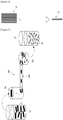
- Figure 1 is a conceptual diagram for explaining a process of producing graphene flakes (GF) (or graphene) through graphite (G).
- a high pressure homogenizer (HPH) used as a method for producing graphene is a device in which a high pressure is applied to a microchannel having a micrometer scale diameter and thus a strong shear force is applied to a passing substance. Particularly, when graphite is exfoliated using the high pressure homogenizer, there is an advantage that a graphene production yield can be increased.
- the graphene is produced as graphite is exfoliated by a shear stress applied to the graphite while a graphite dispersion liquid propelled by ultra-high pressure passes through the microchannel.
- the graphite has a thickness of approximately several hundred nanometers, and the graphene has a thickness of approximately 2 to 30 nm.
- a high pressure homogenizer comprising a channel module which comprises a microchannel through which an object for homogenization passes, wherein the channel module comprises at least one baffle disposed so as to partition the microchannel into a plurality of spaces and the baffle is provided so as to partition the microchannel into two spaces along the width direction or the height direction.
- a high pressure homogenizer comprising a channel module which comprises a microchannel through which an object for homogenization passes, wherein the channel module comprises a front end channel for supplying the object to the microchannel, a back end channel in which the object passing through the microchannel flows into and at least one baffle disposed so as to partition the microchannel into a plurality of spaces, the baffle is provided so as to partition the microchannel into two spaces along the width direction or the height direction, the front end channel is provided so that at least a part of a flow area becomes small along the moving direction of the object and the back end channel is provided so that at least a part of a flow area increases along the moving direction of the object.
- a method for manufacturing graphene using the high pressure homogenizer comprising a step of supplying a solution containing graphite to the channel module and a step of applying pressure to the channel module to pass the solution containing graphite.
- the high pressure homogenizer related to at least one embodiment of the present invention and the method for manufacturing graphene using the same have the following effects.
- productivity in the process of exfoliating a single layer of graphene from graphite using the high pressure homogenizer, productivity can be improved by increasing the exfoliation effective region in the microchannel.
- one or more baffles are disposed in the microchannel in order to increase the region to which a shear stress (shear rate) above the critical shear stress (for example, 10 5 l/s) required for graphene exfoliation is applied.
- a shear stress shear rate
- critical shear stress for example, 10 5 l/s
- Figure 2 is a conceptual diagram showing a high pressure homogenizer (100) related to one embodiment of the present invention
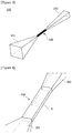
- Figure 3 is a perspective view showing the channel module (200) shown in Figure 2 .
- Figure 4 is a perspective view showing a first embodiment of a channel module
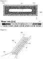
- Figure 5 is a simulation result at the portion A in Figure 4 .
- the high pressure homogenizer (100) means a device in which a high pressure is applied to a microchannel (210) having a micrometer scale diameter and thus a strong shear force is applied to a substance (graphite dispersion liquid) passing therethrough.
- the shear stress is used to perform fragmentation and dispersion to the substance passing through the microchannel (210) and to produce a highly dispersed material.
- the high pressure homogenizer (100) is designed and manufactured for fragmentation and pulverization of substances through the strong shear stress, generally a very short microchannel is used. However, depending on the purpose of use of the high pressure homogenizer (100), a microchannel having a short length may serve as a disadvantage.
- the present invention provides a high pressure homogenizer capable of reducing the number of times of passage of the microchannel without pulverizing the graphene itself within a range where the shear stress required for graphite exfoliation is applied.
- the high pressure homogenizer (100) comprises a channel module (200) comprising a microchannel through which an object for homogenization passes.
- the object is the above-mentioned graphite (G).
- the high pressure homogenizer (100) comprises an inflow part (101) through which the object is supplied toward the channel module (200) and an outflow part (103) through which the object passing through the channel module (200) flows out.
- a reference numeral 10 denotes a container containing a graphite (G) dispersion liquid
- a reference numeral 20 denotes a container containing graphene (GF) recovered from the outflow part (103).
- the high pressure homogenizer (100) comprises a pump for generating a pressure for pressing the object to pass through the channel module (200). While the object passes through the microchannel (210) with the pressure generated by the pump, homogenization is achieved.
- the channel module (200) comprises a front end channel (201) for supplying an object to the microchannel (210) and a back end channel (202) in which the object passing through the microchannel (201) flows into.
- the front end channel (201) is provided so that at least a part of the flow area becomes small along the moving direction of the object
- the back end channel (202) is provided such that at least a part of the flow area increases along the moving direction of the object.
- the microchannel (210) may be provided to have a constant flow area along the moving direction of the object.
- the object is graphite (G), which is exfoliated by a strong shear stress (shear rate) in the microchannel (210) to produce graphene (GF).
- G graphite
- shear rate shear stress
- the length of the microchannel it is preferred for the length of the microchannel to be 2 mm to 1000 mm, in order that the shear force required for graphite exfoliation is applied, and at the same time, the section where the shear force is applied is lengthened, while the energy that the fluid passing through the microchannel (210) collides with the wall surface of the outflow part (103) is reduced, so that the graphene itself is not pulverized. More preferably, the length of the microchannel may be in 2 mm to 60 mm.
- the energy consumption shown in the high pressure homogenizer is divided into energy losses at the microchannel inlet (secondary loss), the microchannel interior (intuition loss) and the microchannel outlet (secondary loss). Specifically, it has been confirmed that the energy consumption is large while the flow area (channel cross-sectional area) changes at the microchannel inlet (front end channel side) and the microchannel outlet (back end channel side), and the energy consumption inside the microchannel is within about 5% of the entire energy consumption.
- the case where the length of the microchannel (210) is 30 mm or more has the same effect as the case where the graphene exfoliation process is repeated 15 times in the high pressure homogenizer having a length in the microchannel (210) of 2 mm. Therefore, by increasing the length of the microchannel (210), it is possible to reduce the number of microchannel passage times, thereby increasing the productivity.
- the microchannel (210) may have a cross section (A) (channel cross section), which is perpendicular to the moving direction of the object for homogenization, of a rectangular shape.
- the microchannel (210) may have a cross section of a rectangular shape in which a width (length in the x-axis direction) is greater than a height (length in the y-axis direction).
- the microchannel (210) has preferably a ratio between width and height of 2:1 or more, and particularly, the microchannel (210) may be formed to have a ratio between width and height of 2:1 to 10:1.
- the width and breadth of the rectangle may be 10 ⁇ m to 50000 ⁇ m, respectively.
- the cross section of the microchannel is circular, but in the present invention, the rectangular shape having a larger surface area than the circular shape is used, whereby the cross-sectional area of the flow channel can be increased. Also, the cross-sectional area of the microchannel may be 1.0 X 10 2 ⁇ m 2 to 1.0 X 10 8 ⁇ m 2 .
- the method for manufacturing graphene also comprises a step of supplying a solution containing graphite (G) to the channel module (200) and a step of applying pressure to the channel module (200) to pass the solution containing the graphite (G).
- the pressure may be in 100 to 3000 bar.
- the graphene (GF) dispersion liquid can be recovered from the outflow part (103) and then again reintroduced into the inflow part (101).
- the reintroduction process may be repeated 2 to 30 times.
- the reintroduction process may also be repeated using a single high pressure homogenizer or using a plurality of high pressure homogenizers sequentially.
- the method for manufacturing graphene may comprise a step of recovering and drying the graphene from the recovered graphene (GF) dispersion liquid.
- the recovering step may be carried out by centrifugation, filtration under reduced pressure or pressure filtration.
- the drying step may be performed by vacuum drying or general drying under a temperature of about 30 to 200°C.
- the graphene produced according to the present invention has an advantage that is advantageous in expressing characteristics inherent to graphene, since its size is large and uniform.
- Figure 6 is a perspective view showing a second embodiment of a channel module
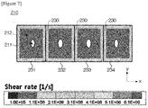
- Figure 7 is a simulation result of the portion B in Figure 6 .
- the channel module (200) comprises at least one baffle (230) disposed to partition the microchannel (210) into a plurality of spaces.
- the baffle (230) is provided to partition the microchannel into two spaces along the width direction (x-axis direction) or the height direction (y-axis direction).
- the channel module (200) is provided so that the object passes through the respective spaces (231, 232, 233, 234) partitioned by the baffles (230).
- the simulation was performed using the channel module (200) as shown in Figure 3 .
- the microchannel (210) has a length of 2 mm, a width of 320 ⁇ m, and a height of 100 ⁇ m.
- the critical shear stress (shear rate) required for graphene exfoliation was based on 10 5 l/s.
- the entire flow channel cross-sectional area of the region A in Figure 5 is the same as the entire flow channel cross-sectional area of the region B in Figure 7 . That is, the widths and heights of the microchannel (210) shown in Figures 5 and 7 are the same.
- the flow channel cross-sectional area was partitioned into four (231 to 234) by disposing three baffles (230) at equal intervals along the width direction (x-axis direction) in the microchannel (210).
- a shear stress lower than the critical shear stress (shear rate) is generated in the central region (211) on the basis of the flow channel cross section.
- a reference numeral (212) indicates the exfoliation effective region.
- the exfoliation effective region represents a region where a shear stress greater than the critical shear stress (shear rate, 10 5 l/s) is generated.
- productivity in the process of exfoliating a single layer of graphene from graphite using the high pressure homogenizer, productivity can be improved by increasing the exfoliation effective region in the microchannel.
- one or more baffles are disposed in the microchannel in order to increase the region where the shear stress (shear rate) above the critical shear stress (for example, 10 5 l/s) required for graphene exfoliation is applied.
- the baffle By partitioning the inside of the microchannel by the baffle, it is possible to increase the wall area and to increase the exfoliation effective region showing a large shear stress.
- the present invention it is possible to increase a region where a shear stress above the critical shear stress (for example, 10 5 l/s) required for graphene exfoliation is applied through the baffles, and by partitioning the inside of the microchannel by the baffle, it is possible to increase the wall area and to increase the exfoliation effective region.
- a shear stress above the critical shear stress for example, 10 5 l/s
Landscapes
- Chemical & Material Sciences (AREA)
- Organic Chemistry (AREA)
- Chemical Kinetics & Catalysis (AREA)
- Engineering & Computer Science (AREA)
- Materials Engineering (AREA)
- Nanotechnology (AREA)
- Inorganic Chemistry (AREA)
- Dispersion Chemistry (AREA)
- Carbon And Carbon Compounds (AREA)
- Physical Or Chemical Processes And Apparatus (AREA)
Abstract
Description
- The present invention relates to a high pressure homogenizer and a method for producing graphene using the same.
- The present application claims the benefit of priority based on Korean Patent Application No.
10-2016-0057535 filed on May 11, 2016 - Graphene is a metalloid material with a thickness corresponding to a carbon atomic layer while forming a hexagonally connected arrangement of carbon atoms by sp2 bonds in two dimensions. Recently, a graphene sheet having one carbon atom layer has been reported to have very good electrical conductivity.
- Due to the excellent properties of graphene, various methods have been proposed or studied to more effectively mass-produce graphene from carbon-based materials such as graphite. In particular, various studies have been made on a method for easily manufacturing graphene sheets or flakes having a thinner thickness and a larger area.
-
Figure 1 is a conceptual diagram for explaining a process of producing graphene flakes (GF) (or graphene) through graphite (G). - A high pressure homogenizer (HPH) used as a method for producing graphene is a device in which a high pressure is applied to a microchannel having a micrometer scale diameter and thus a strong shear force is applied to a passing substance. Particularly, when graphite is exfoliated using the high pressure homogenizer, there is an advantage that a graphene production yield can be increased.
- Specifically, when a high pressure homogenizer is used, the graphene is produced as graphite is exfoliated by a shear stress applied to the graphite while a graphite dispersion liquid propelled by ultra-high pressure passes through the microchannel. At this time, the graphite has a thickness of approximately several hundred nanometers, and the graphene has a thickness of approximately 2 to 30 nm.
- On the other hand, for exfoliation of graphene, it is important to form a proper flow field in the microchannel so as to generate a shear stress at a level capable of breaking an interlayer bonding force. In the graphene exfoliation process using the high pressure homogenizer, the velocity gradient is increased near the wall surface inside the microchannel due to the adhesion condition of the wall surface, so that a large shear stress is generated. However, since the velocity gradient is small at the center portion to show a small shear stress, which is lower than the critical shear stress required for exfoliation, there is a problem that the exfoliation is not performed.
- It is a problem to be solved by the present invention to provide a high pressure homogenizer capable of increasing an exfoliation effective region within a microchannel and a method for manufacturing graphene using the same.
- To solve the problem as described above, according to one aspect of the present invention, there is provided a high pressure homogenizer comprising a channel module which comprises a microchannel through which an object for homogenization passes, wherein the channel module comprises at least one baffle disposed so as to partition the microchannel into a plurality of spaces and the baffle is provided so as to partition the microchannel into two spaces along the width direction or the height direction.
- Also, according to another aspect of the present invention, there is provided a high pressure homogenizer comprising a channel module which comprises a microchannel through which an object for homogenization passes, wherein the channel module comprises a front end channel for supplying the object to the microchannel, a back end channel in which the object passing through the microchannel flows into and at least one baffle disposed so as to partition the microchannel into a plurality of spaces, the baffle is provided so as to partition the microchannel into two spaces along the width direction or the height direction, the front end channel is provided so that at least a part of a flow area becomes small along the moving direction of the object and the back end channel is provided so that at least a part of a flow area increases along the moving direction of the object.
- In addition, according to another aspect of the present invention, in a method for manufacturing graphene using the high pressure homogenizer, there is provided a method for manufacturing graphene comprising a step of supplying a solution containing graphite to the channel module and a step of applying pressure to the channel module to pass the solution containing graphite.
- As described above, the high pressure homogenizer related to at least one embodiment of the present invention and the method for manufacturing graphene using the same have the following effects.
- According to the present invention, in the process of exfoliating a single layer of graphene from graphite using the high pressure homogenizer, productivity can be improved by increasing the exfoliation effective region in the microchannel.
- Specifically, one or more baffles are disposed in the microchannel in order to increase the region to which a shear stress (shear rate) above the critical shear stress (for example, 105 l/s) required for graphene exfoliation is applied. By partitioning the inside of the microchannel by the baffle, the wall area can be increased and the exfoliation effective region showing large shear stress can be increased.
-
-
Figure 1 is a conceptual diagram for explaining the process of producing graphene flakes through graphite. -
Figure 2 is a conceptual diagram showing a high pressure homogenizer related to one embodiment of the present invention. -
Figure 3 is a perspective view showing the channel module shown inFigure 2 . -
Figure 4 is a perspective view showing a first embodiment of a channel module. -
Figure 5 is a simulation result at the portion A inFigure 4 -
Figure 6 is a perspective view showing a second embodiment of the channel module. -
Figure 7 is a simulation result at the portion B inFigure 6 . - Hereinafter, a high pressure homogenizer according to one embodiment of the present invention and a method for manufacturing graphene using the same will be described in detail with reference to the accompanying drawings.
- In addition, the same or similar reference numerals are given to the same or corresponding components regardless of reference numerals, of which redundant explanations will be omitted, and for convenience of explanation, the size and shape of each constituent member as shown may be exaggerated or reduced.
-
Figure 2 is a conceptual diagram showing a high pressure homogenizer (100) related to one embodiment of the present invention, andFigure 3 is a perspective view showing the channel module (200) shown inFigure 2 . - Also,
Figure 4 is a perspective view showing a first embodiment of a channel module, andFigure 5 is a simulation result at the portion A inFigure 4 . - The high pressure homogenizer (100) means a device in which a high pressure is applied to a microchannel (210) having a micrometer scale diameter and thus a strong shear force is applied to a substance (graphite dispersion liquid) passing therethrough. The shear stress is used to perform fragmentation and dispersion to the substance passing through the microchannel (210) and to produce a highly dispersed material.
- On the other hand, since the high pressure homogenizer (100) is designed and manufactured for fragmentation and pulverization of substances through the strong shear stress, generally a very short microchannel is used. However, depending on the purpose of use of the high pressure homogenizer (100), a microchannel having a short length may serve as a disadvantage.
- Particularly, in the case of manufacturing graphene by exfoliating graphite (G) with a high pressure homogenizer (100), like the present invention, when the microchannel having a short length is used, there is a problem that the productivity is lowered because the number of times of passage of the microchannel must be increased in order to produce thin and uniform graphene. Besides, if the length of the microchannel is short, the velocity of the fluid passing through the microchannel becomes fast, and the energy that a fluid collides with the wall surface of an outflow part (103) becomes high. Due to such a collision, there is a problem that the size of the graphene to be produced decreases because the graphene itself is pulverized. Therefore, the present invention provides a high pressure homogenizer capable of reducing the number of times of passage of the microchannel without pulverizing the graphene itself within a range where the shear stress required for graphite exfoliation is applied.
- Referring to
Figure 2 , the high pressure homogenizer (100) comprises a channel module (200) comprising a microchannel through which an object for homogenization passes. The object is the above-mentioned graphite (G). The high pressure homogenizer (100) comprises an inflow part (101) through which the object is supplied toward the channel module (200) and an outflow part (103) through which the object passing through the channel module (200) flows out. InFigure 2 , a reference numeral 10 denotes a container containing a graphite (G) dispersion liquid, and areference numeral 20 denotes a container containing graphene (GF) recovered from the outflow part (103). In addition, the high pressure homogenizer (100) comprises a pump for generating a pressure for pressing the object to pass through the channel module (200). While the object passes through the microchannel (210) with the pressure generated by the pump, homogenization is achieved. - On the other hand, the channel module (200) comprises a front end channel (201) for supplying an object to the microchannel (210) and a back end channel (202) in which the object passing through the microchannel (201) flows into. At this time, the front end channel (201) is provided so that at least a part of the flow area becomes small along the moving direction of the object, and the back end channel (202) is provided such that at least a part of the flow area increases along the moving direction of the object. In addition, the microchannel (210) may be provided to have a constant flow area along the moving direction of the object.
- In the present invention, the object is graphite (G), which is exfoliated by a strong shear stress (shear rate) in the microchannel (210) to produce graphene (GF). At this time, it is preferred for the length of the microchannel to be 2 mm to 1000 mm, in order that the shear force required for graphite exfoliation is applied, and at the same time, the section where the shear force is applied is lengthened, while the energy that the fluid passing through the microchannel (210) collides with the wall surface of the outflow part (103) is reduced, so that the graphene itself is not pulverized. More preferably, the length of the microchannel may be in 2 mm to 60 mm.
- As a result of analyzing the flow inside the high pressure homogenizer (100) through the flow field simulation, it has been confirmed that the energy consumption shown in the high pressure homogenizer is divided into energy losses at the microchannel inlet (secondary loss), the microchannel interior (intuition loss) and the microchannel outlet (secondary loss). Specifically, it has been confirmed that the energy consumption is large while the flow area (channel cross-sectional area) changes at the microchannel inlet (front end channel side) and the microchannel outlet (back end channel side), and the energy consumption inside the microchannel is within about 5% of the entire energy consumption. Based on this, it has been confirmed that even if the length of the microchannel (210) is increased, the resulting decrease of the energy consumption and the flow rate is insignificant and the shear stress required for graphene exfoliation is applied over the entire length of the microchannel (210).
- Also, it has been confirmed that the case where the length of the microchannel (210) is 30 mm or more has the same effect as the case where the graphene exfoliation process is repeated 15 times in the high pressure homogenizer having a length in the microchannel (210) of 2 mm. Therefore, by increasing the length of the microchannel (210), it is possible to reduce the number of microchannel passage times, thereby increasing the productivity.
- Referring to
Figures 4 and5 , the microchannel (210) may have a cross section (A) (channel cross section), which is perpendicular to the moving direction of the object for homogenization, of a rectangular shape. Also, the microchannel (210) may have a cross section of a rectangular shape in which a width (length in the x-axis direction) is greater than a height (length in the y-axis direction). In addition, the microchannel (210) has preferably a ratio between width and height of 2:1 or more, and particularly, the microchannel (210) may be formed to have a ratio between width and height of 2:1 to 10:1. Furthermore, the width and breadth of the rectangle may be 10 µm to 50000 µm, respectively. In the conventional high pressure homogenizer, the cross section of the microchannel is circular, but in the present invention, the rectangular shape having a larger surface area than the circular shape is used, whereby the cross-sectional area of the flow channel can be increased. Also, the cross-sectional area of the microchannel may be 1.0 X 102 µm2 to 1.0 X 108 µm2. - In the method for manufacturing graphene using the high pressure homogenizer (100), the method for manufacturing graphene also comprises a step of supplying a solution containing graphite (G) to the channel module (200) and a step of applying pressure to the channel module (200) to pass the solution containing the graphite (G). The pressure may be in 100 to 3000 bar. In addition, the graphene (GF) dispersion liquid can be recovered from the outflow part (103) and then again reintroduced into the inflow part (101). The reintroduction process may be repeated 2 to 30 times. The reintroduction process may also be repeated using a single high pressure homogenizer or using a plurality of high pressure homogenizers sequentially.
- In addition, the method for manufacturing graphene may comprise a step of recovering and drying the graphene from the recovered graphene (GF) dispersion liquid. The recovering step may be carried out by centrifugation, filtration under reduced pressure or pressure filtration. The drying step may be performed by vacuum drying or general drying under a temperature of about 30 to 200°C. Furthermore, the graphene produced according to the present invention has an advantage that is advantageous in expressing characteristics inherent to graphene, since its size is large and uniform.
-
Figure 6 is a perspective view showing a second embodiment of a channel module, andFigure 7 is a simulation result of the portion B inFigure 6 . - In this embodiment, the channel module (200) comprises at least one baffle (230) disposed to partition the microchannel (210) into a plurality of spaces. Also, the baffle (230) is provided to partition the microchannel into two spaces along the width direction (x-axis direction) or the height direction (y-axis direction). Hereinafter, for convenience of explanation, a case where the microchannel is partitioned into a plurality of spaces along the width direction will be described as an example. For example, the channel module (200) is provided so that the object passes through the respective spaces (231, 232, 233, 234) partitioned by the baffles (230).
- Referring to the simulation results of
Figures 5 and7 , the simulation was performed using the channel module (200) as shown inFigure 3 . At this time, the microchannel (210) has a length of 2 mm, a width of 320 µm, and a height of 100 µm. - In addition, the critical shear stress (shear rate) required for graphene exfoliation was based on 105 l/s. The entire flow channel cross-sectional area of the region A in
Figure 5 is the same as the entire flow channel cross-sectional area of the region B inFigure 7 . That is, the widths and heights of the microchannel (210) shown inFigures 5 and7 are the same. However, in the second embodiment, the flow channel cross-sectional area was partitioned into four (231 to 234) by disposing three baffles (230) at equal intervals along the width direction (x-axis direction) in the microchannel (210). Furthermore, inFigures 5 and7 , the graphite dispersion liquids flowing through the microchannels were the same and experimented under the same flow rate condition. However, in order to satisfy the same flow rate condition, the pressure (pump pressure) (about 9.3 bar) applied to the microchannel shown inFigure 7 is larger than the pressure (about 6 bar) applied to the microchannel shown inFigure 5 . - As a result of the experiment, in the case of the first embodiment without installing any baffle in the microchannel, it has been confirmed that a shear stress lower than the critical shear stress (shear rate) is generated in the central region (211) on the basis of the flow channel cross section. In
Figure 5 , a reference numeral (212) (blue region) indicates the exfoliation effective region. As described above, the exfoliation effective region represents a region where a shear stress greater than the critical shear stress (shear rate, 105 l/s) is generated. - Alternatively, in
Figure 7 , it can be confirmed that the exfoliation effective area (blue region) increases (about 23%) as compared withFigure 5 . - According to the present invention, in the process of exfoliating a single layer of graphene from graphite using the high pressure homogenizer, productivity can be improved by increasing the exfoliation effective region in the microchannel.
- Specifically, one or more baffles are disposed in the microchannel in order to increase the region where the shear stress (shear rate) above the critical shear stress (for example, 105 l/s) required for graphene exfoliation is applied. By partitioning the inside of the microchannel by the baffle, it is possible to increase the wall area and to increase the exfoliation effective region showing a large shear stress.
- The preferred examples of the present invention as described above are disclosed for illustrative purposes, which can be modified, changed and added within thought and scope of the present invention by those skilled in the art and it will be considered that such modification, change and addition fall within the following claims.
- According to the present invention, it is possible to increase a region where a shear stress above the critical shear stress (for example, 105 l/s) required for graphene exfoliation is applied through the baffles, and by partitioning the inside of the microchannel by the baffle, it is possible to increase the wall area and to increase the exfoliation effective region.
Claims (14)
- A high pressure homogenizer comprisinga channel module which comprises a microchannel through which an object for homogenization passes,wherein the channel module comprises at least one baffle disposed so as to partition said microchannel into a plurality of spaces andthe baffle is provided so as to partition the microchannel into two spaces along the width direction or the height direction.
- The high pressure homogenizer according to claim 1,
wherein said channel module is provided so that the object passes through each space partitioned by the baffle. - The high pressure homogenizer according to claim 1,
wherein said microchannel has a length of 2 mm to 1000 mm. - The high pressure homogenizer according to claim 1,
wherein the microchannel has a cross section, which is perpendicular to the moving direction of the object for homogenization, of a rectangular shape. - The high pressure homogenizer according to claim 4,
wherein said microchannel has a cross section of a rectangular shape in which a width is greater than a height. - The high pressure homogenizer according to claim 4,
wherein said microchannel is formed to have a ratio between width and height of 2:1 to 10:1. - The high pressure homogenizer according to claim 1,
wherein the microchannel has a cross-sectional area of 1.0 X 102 µm2 to 1.0 X 108 µm2. - A high pressure homogenizer comprisinga channel module which comprises a microchannel through which an object for homogenization passes,wherein the channel module comprises a front end channel for supplying the object to the microchannel, a back end channel in which the object passing through the microchannel flows into and at least one baffle disposed so as to partition the microchannel into a plurality of spaces,the baffle is provided so as to partition the microchannel into two spaces along the width direction or the height direction,the front end channel is provided so that at least a part of a flow area becomes small along the moving direction of the object and the back end channel is provided so that at least a part of a flow area increases along the moving direction of the object.
- The high pressure homogenizer according to claim 8,
wherein said channel module is provided so that the object passes through each space partitioned by the baffle. - The high pressure homogenizer according to claim 8,
wherein the microchannel has a constant flow area along the moving direction of the object. - The high pressure homogenizer according to claim 8,
wherein the microchannel has a cross section, which is perpendicular to the moving direction of the object for homogenization, of a rectangular shape. - The high pressure homogenizer according to claim 8,
wherein said microchannel has a cross section of a rectangular shape in which a width is greater than a height. - A method for manufacturing graphene using the high pressure homogenizer according to any one of claims 1 to 7, comprising
a step of supplying a solution containing graphite to the channel module; and a step of applying pressure to the channel module to pass the solution containing graphite. - The method for manufacturing graphene according to claim 13,
wherein said pressure is in 100 to 3000 bar.
Applications Claiming Priority (2)
| Application Number | Priority Date | Filing Date | Title |
|---|---|---|---|
| KR1020160057535A KR102079141B1 (en) | 2016-05-11 | 2016-05-11 | High pressure homogenizer and manufacturing method for Graphene using the same |
| PCT/KR2017/004754 WO2017196037A1 (en) | 2016-05-11 | 2017-05-08 | High pressure homogenizer and method for manufacturing graphene using same |
Publications (3)
| Publication Number | Publication Date |
|---|---|
| EP3456685A1 true EP3456685A1 (en) | 2019-03-20 |
| EP3456685A4 EP3456685A4 (en) | 2019-06-05 |
| EP3456685B1 EP3456685B1 (en) | 2020-07-01 |
Family
ID=60267201
Family Applications (1)
| Application Number | Title | Priority Date | Filing Date |
|---|---|---|---|
| EP17796337.8A Active EP3456685B1 (en) | 2016-05-11 | 2017-05-08 | Method for manufacturing graphene with a high pressure homogenizer |
Country Status (6)
| Country | Link |
|---|---|
| US (1) | US10807056B2 (en) |
| EP (1) | EP3456685B1 (en) |
| JP (1) | JP6688398B2 (en) |
| KR (1) | KR102079141B1 (en) |
| CN (1) | CN109071230B (en) |
| WO (1) | WO2017196037A1 (en) |
Families Citing this family (4)
| Publication number | Priority date | Publication date | Assignee | Title |
|---|---|---|---|---|
| EP3636592A1 (en) * | 2018-10-12 | 2020-04-15 | Advanced Material Development Limited | Liquid-exfoliated nanomaterials |
| CN109761228B (en) * | 2019-03-29 | 2023-09-15 | 广州大学 | A method and device for efficient exfoliation of two-dimensional materials at low Reynolds number |
| KR102703533B1 (en) * | 2019-11-15 | 2024-09-06 | 주식회사 엘지에너지솔루션 | Method for manufacturing graphene nano-sheet |
| US11512265B1 (en) * | 2021-07-23 | 2022-11-29 | Turtle Wax, Inc. | Water-based graphene dispersion made by shear stabilization |
Family Cites Families (18)
| Publication number | Priority date | Publication date | Assignee | Title |
|---|---|---|---|---|
| DE69413012T2 (en) * | 1993-03-19 | 1999-03-25 | Du Pont | INTEGRATED DEVICE FOR CHEMICAL PROCESS STEPS AND MANUFACTURING METHOD THEREFOR |
| US6969505B2 (en) * | 2002-08-15 | 2005-11-29 | Velocys, Inc. | Process for conducting an equilibrium limited chemical reaction in a single stage process channel |
| DE10317451A1 (en) * | 2003-04-16 | 2004-11-18 | Degussa Ag | Reactor for heterogeneously catalyzed reactions |
| EP2397457A3 (en) | 2006-03-23 | 2013-11-20 | Velocys Inc. | Process for making styrene using microchannel process technology |
| US8048383B2 (en) | 2006-04-20 | 2011-11-01 | Velocys, Inc. | Process for treating and/or forming a non-Newtonian fluid using microchannel process technology |
| JP5030520B2 (en) | 2006-09-29 | 2012-09-19 | 富士フイルム株式会社 | Fluid mixing method and microdevice |
| US8178075B2 (en) * | 2008-08-13 | 2012-05-15 | Air Products And Chemicals, Inc. | Tubular reactor with jet impingement heat transfer |
| JP2010234367A (en) * | 2009-03-11 | 2010-10-21 | Sekisui Chem Co Ltd | Method for producing surface-modified inorganic nanoparticles |
| US8968695B2 (en) | 2009-08-10 | 2015-03-03 | Idt International Co., Ltd. | Method of producing nano-size graphene-based material and an equipment for producing the same |
| RS52565B (en) | 2009-12-03 | 2013-04-30 | Novartis Ag | METHOD OF INTERACTION AND REVERSE PRESSURE FOR MICROFLUIDIZATION |
| KR101264316B1 (en) * | 2010-11-09 | 2013-05-22 | 한국전기연구원 | manufacturing method of single-layered reduced graphene oxide dispersion solution using shear stress and the single-layered reduced graphene oxide dispersion solution thereby |
| JP5990256B2 (en) * | 2011-04-15 | 2016-09-07 | ザ ユニバーシティ オブ ブリティッシュ コロンビアThe University Of British Columbia | Particle separation method and apparatus |
| KR101682007B1 (en) * | 2013-12-26 | 2016-12-02 | 주식회사 엘지화학 | Preparation method of graphene |
| KR101666478B1 (en) * | 2013-12-26 | 2016-10-14 | 주식회사 엘지화학 | Preparation method of graphene and dispersed composition of graphene |
| WO2016093664A2 (en) * | 2014-12-12 | 2016-06-16 | 주식회사 엘지화학 | Block copolymer and method for preparing graphene by using same |
| GB201517737D0 (en) * | 2015-10-07 | 2015-11-18 | Cambridge Entpr Ltd | Layered materials and methods for their processing |
| CN105498656B (en) * | 2015-12-28 | 2017-05-17 | 东南大学 | Preparing device of shell-core functional material |
| CN105540575A (en) * | 2016-01-28 | 2016-05-04 | 成都新柯力化工科技有限公司 | Method for preparing graphene by using high-pressure homogenizer delamination |
-
2016
- 2016-05-11 KR KR1020160057535A patent/KR102079141B1/en active Active
-
2017
- 2017-05-08 WO PCT/KR2017/004754 patent/WO2017196037A1/en not_active Ceased
- 2017-05-08 CN CN201780027708.8A patent/CN109071230B/en active Active
- 2017-05-08 US US16/076,192 patent/US10807056B2/en active Active
- 2017-05-08 JP JP2018541344A patent/JP6688398B2/en active Active
- 2017-05-08 EP EP17796337.8A patent/EP3456685B1/en active Active
Also Published As
| Publication number | Publication date |
|---|---|
| KR20170127208A (en) | 2017-11-21 |
| US20200122108A1 (en) | 2020-04-23 |
| CN109071230A (en) | 2018-12-21 |
| JP2019506295A (en) | 2019-03-07 |
| EP3456685B1 (en) | 2020-07-01 |
| KR102079141B1 (en) | 2020-02-19 |
| WO2017196037A1 (en) | 2017-11-16 |
| US10807056B2 (en) | 2020-10-20 |
| JP6688398B2 (en) | 2020-04-28 |
| CN109071230B (en) | 2022-02-01 |
| EP3456685A4 (en) | 2019-06-05 |
Similar Documents
| Publication | Publication Date | Title |
|---|---|---|
| US11820665B2 (en) | High-pressure homogenizer and method for manufacturing graphene using the same | |
| US10807056B2 (en) | High pressure homogenizer and method for manufacturing graphene using the same | |
| US11472158B2 (en) | Continuous production of exfoliated 2D layered materials by compressive flow | |
| Jambhulkar et al. | Aligned Ti3C2T x MXene for 3D micropatterning via additive manufacturing | |
| Chung et al. | Design and experiments of a short-mixing-length baffled microreactor and its application to microfluidic synthesis of nanoparticles | |
| CN102458630B (en) | Microfluidic apparatus and method for generating a dispersion | |
| CN108137328B (en) | Apparatus and method for mass production of atomically thin two-dimensional materials including graphene | |
| Jafarpour et al. | An ecologically friendly process for graphene exfoliation based on the “hydrodynamic cavitation on a chip” concept | |
| JP6674531B2 (en) | Apparatus for stripping plate material containing microchannel | |
| KR102061780B1 (en) | Device for exfoliation of plate-shaped materials comprising optimized outlet | |
| Choi et al. | Wide-range size fractionation of graphene oxide by flow field-flow fractionation | |
| JP5625900B2 (en) | Microchannel structure and method for producing microparticles using the same | |
| CN109562946B (en) | Method for stripping particles | |
| DE102006016482A1 (en) | Passive micro-mixer for single- or multi-phase fluids has two inlets and an outlet plus numerous mixer elements located in different three-dimensional planes | |
| JP2006053060A (en) | Fine particle manufacturing method and microchannel structure therefor | |
| DE202005005628U1 (en) | Passive micro-mixer for single- or multi-phase fluids has two inlets and an outlet plus numerous mixer elements located in different three-dimensional planes | |
| Duraiswamy et al. | Nanoparticle factories in flowing foams | |
| JP2018118868A (en) | Graphene dispersion manufacturing method, graphene dispersion manufacturing apparatus, and graphene dispersion | |
| JP2015085299A (en) | Microchannel device with microvalve | |
| KR20100010078A (en) | A microchannel having walls installed with grooves |
Legal Events
| Date | Code | Title | Description |
|---|---|---|---|
| STAA | Information on the status of an ep patent application or granted ep patent |
Free format text: STATUS: THE INTERNATIONAL PUBLICATION HAS BEEN MADE |
|
| PUAI | Public reference made under article 153(3) epc to a published international application that has entered the european phase |
Free format text: ORIGINAL CODE: 0009012 |
|
| STAA | Information on the status of an ep patent application or granted ep patent |
Free format text: STATUS: REQUEST FOR EXAMINATION WAS MADE |
|
| 17P | Request for examination filed |
Effective date: 20180807 |
|
| AK | Designated contracting states |
Kind code of ref document: A1 Designated state(s): AL AT BE BG CH CY CZ DE DK EE ES FI FR GB GR HR HU IE IS IT LI LT LU LV MC MK MT NL NO PL PT RO RS SE SI SK SM TR |
|
| AX | Request for extension of the european patent |
Extension state: BA ME |
|
| A4 | Supplementary search report drawn up and despatched |
Effective date: 20190506 |
|
| RIC1 | Information provided on ipc code assigned before grant |
Ipc: C01B 32/182 20170101AFI20190429BHEP Ipc: B01J 3/00 20060101ALI20190429BHEP Ipc: B01J 19/00 20060101ALI20190429BHEP |
|
| RIN1 | Information on inventor provided before grant (corrected) |
Inventor name: IM, YE HOON Inventor name: LEE, JIN YEONG Inventor name: KWON, WON JONG Inventor name: YOO, KWANG HYUN Inventor name: KIM, EUN JEONG |
|
| RIN1 | Information on inventor provided before grant (corrected) |
Inventor name: IM, YE HOON Inventor name: KIM, EUN JEONG Inventor name: LEE, JIN YEONG Inventor name: YOO, KWANG HYUN Inventor name: KWON, WON JONG |
|
| DAV | Request for validation of the european patent (deleted) | ||
| DAX | Request for extension of the european patent (deleted) | ||
| GRAP | Despatch of communication of intention to grant a patent |
Free format text: ORIGINAL CODE: EPIDOSNIGR1 |
|
| STAA | Information on the status of an ep patent application or granted ep patent |
Free format text: STATUS: GRANT OF PATENT IS INTENDED |
|
| INTG | Intention to grant announced |
Effective date: 20200303 |
|
| GRAS | Grant fee paid |
Free format text: ORIGINAL CODE: EPIDOSNIGR3 |
|
| GRAA | (expected) grant |
Free format text: ORIGINAL CODE: 0009210 |
|
| STAA | Information on the status of an ep patent application or granted ep patent |
Free format text: STATUS: THE PATENT HAS BEEN GRANTED |
|
| AK | Designated contracting states |
Kind code of ref document: B1 Designated state(s): AL AT BE BG CH CY CZ DE DK EE ES FI FR GB GR HR HU IE IS IT LI LT LU LV MC MK MT NL NO PL PT RO RS SE SI SK SM TR |
|
| REG | Reference to a national code |
Ref country code: CH Ref legal event code: EP Ref country code: AT Ref legal event code: REF Ref document number: 1286031 Country of ref document: AT Kind code of ref document: T Effective date: 20200715 |
|
| REG | Reference to a national code |
Ref country code: IE Ref legal event code: FG4D |
|
| REG | Reference to a national code |
Ref country code: DE Ref legal event code: R096 Ref document number: 602017019149 Country of ref document: DE |
|
| REG | Reference to a national code |
Ref country code: LT Ref legal event code: MG4D |
|
| PG25 | Lapsed in a contracting state [announced via postgrant information from national office to epo] |
Ref country code: BG Free format text: LAPSE BECAUSE OF FAILURE TO SUBMIT A TRANSLATION OF THE DESCRIPTION OR TO PAY THE FEE WITHIN THE PRESCRIBED TIME-LIMIT Effective date: 20201001 |
|
| REG | Reference to a national code |
Ref country code: NL Ref legal event code: MP Effective date: 20200701 |
|
| REG | Reference to a national code |
Ref country code: AT Ref legal event code: MK05 Ref document number: 1286031 Country of ref document: AT Kind code of ref document: T Effective date: 20200701 |
|
| PG25 | Lapsed in a contracting state [announced via postgrant information from national office to epo] |
Ref country code: FI Free format text: LAPSE BECAUSE OF FAILURE TO SUBMIT A TRANSLATION OF THE DESCRIPTION OR TO PAY THE FEE WITHIN THE PRESCRIBED TIME-LIMIT Effective date: 20200701 Ref country code: GR Free format text: LAPSE BECAUSE OF FAILURE TO SUBMIT A TRANSLATION OF THE DESCRIPTION OR TO PAY THE FEE WITHIN THE PRESCRIBED TIME-LIMIT Effective date: 20201002 Ref country code: NO Free format text: LAPSE BECAUSE OF FAILURE TO SUBMIT A TRANSLATION OF THE DESCRIPTION OR TO PAY THE FEE WITHIN THE PRESCRIBED TIME-LIMIT Effective date: 20201001 Ref country code: SE Free format text: LAPSE BECAUSE OF FAILURE TO SUBMIT A TRANSLATION OF THE DESCRIPTION OR TO PAY THE FEE WITHIN THE PRESCRIBED TIME-LIMIT Effective date: 20200701 Ref country code: AT Free format text: LAPSE BECAUSE OF FAILURE TO SUBMIT A TRANSLATION OF THE DESCRIPTION OR TO PAY THE FEE WITHIN THE PRESCRIBED TIME-LIMIT Effective date: 20200701 Ref country code: HR Free format text: LAPSE BECAUSE OF FAILURE TO SUBMIT A TRANSLATION OF THE DESCRIPTION OR TO PAY THE FEE WITHIN THE PRESCRIBED TIME-LIMIT Effective date: 20200701 Ref country code: CZ Free format text: LAPSE BECAUSE OF FAILURE TO SUBMIT A TRANSLATION OF THE DESCRIPTION OR TO PAY THE FEE WITHIN THE PRESCRIBED TIME-LIMIT Effective date: 20200701 Ref country code: PT Free format text: LAPSE BECAUSE OF FAILURE TO SUBMIT A TRANSLATION OF THE DESCRIPTION OR TO PAY THE FEE WITHIN THE PRESCRIBED TIME-LIMIT Effective date: 20201102 Ref country code: ES Free format text: LAPSE BECAUSE OF FAILURE TO SUBMIT A TRANSLATION OF THE DESCRIPTION OR TO PAY THE FEE WITHIN THE PRESCRIBED TIME-LIMIT Effective date: 20200701 Ref country code: LT Free format text: LAPSE BECAUSE OF FAILURE TO SUBMIT A TRANSLATION OF THE DESCRIPTION OR TO PAY THE FEE WITHIN THE PRESCRIBED TIME-LIMIT Effective date: 20200701 |
|
| PG25 | Lapsed in a contracting state [announced via postgrant information from national office to epo] |
Ref country code: PL Free format text: LAPSE BECAUSE OF FAILURE TO SUBMIT A TRANSLATION OF THE DESCRIPTION OR TO PAY THE FEE WITHIN THE PRESCRIBED TIME-LIMIT Effective date: 20200701 Ref country code: LV Free format text: LAPSE BECAUSE OF FAILURE TO SUBMIT A TRANSLATION OF THE DESCRIPTION OR TO PAY THE FEE WITHIN THE PRESCRIBED TIME-LIMIT Effective date: 20200701 Ref country code: RS Free format text: LAPSE BECAUSE OF FAILURE TO SUBMIT A TRANSLATION OF THE DESCRIPTION OR TO PAY THE FEE WITHIN THE PRESCRIBED TIME-LIMIT Effective date: 20200701 Ref country code: IS Free format text: LAPSE BECAUSE OF FAILURE TO SUBMIT A TRANSLATION OF THE DESCRIPTION OR TO PAY THE FEE WITHIN THE PRESCRIBED TIME-LIMIT Effective date: 20201101 |
|
| PG25 | Lapsed in a contracting state [announced via postgrant information from national office to epo] |
Ref country code: NL Free format text: LAPSE BECAUSE OF FAILURE TO SUBMIT A TRANSLATION OF THE DESCRIPTION OR TO PAY THE FEE WITHIN THE PRESCRIBED TIME-LIMIT Effective date: 20200701 |
|
| REG | Reference to a national code |
Ref country code: DE Ref legal event code: R097 Ref document number: 602017019149 Country of ref document: DE |
|
| PG25 | Lapsed in a contracting state [announced via postgrant information from national office to epo] |
Ref country code: IT Free format text: LAPSE BECAUSE OF FAILURE TO SUBMIT A TRANSLATION OF THE DESCRIPTION OR TO PAY THE FEE WITHIN THE PRESCRIBED TIME-LIMIT Effective date: 20200701 Ref country code: SM Free format text: LAPSE BECAUSE OF FAILURE TO SUBMIT A TRANSLATION OF THE DESCRIPTION OR TO PAY THE FEE WITHIN THE PRESCRIBED TIME-LIMIT Effective date: 20200701 Ref country code: EE Free format text: LAPSE BECAUSE OF FAILURE TO SUBMIT A TRANSLATION OF THE DESCRIPTION OR TO PAY THE FEE WITHIN THE PRESCRIBED TIME-LIMIT Effective date: 20200701 Ref country code: RO Free format text: LAPSE BECAUSE OF FAILURE TO SUBMIT A TRANSLATION OF THE DESCRIPTION OR TO PAY THE FEE WITHIN THE PRESCRIBED TIME-LIMIT Effective date: 20200701 Ref country code: DK Free format text: LAPSE BECAUSE OF FAILURE TO SUBMIT A TRANSLATION OF THE DESCRIPTION OR TO PAY THE FEE WITHIN THE PRESCRIBED TIME-LIMIT Effective date: 20200701 |
|
| PLBE | No opposition filed within time limit |
Free format text: ORIGINAL CODE: 0009261 |
|
| STAA | Information on the status of an ep patent application or granted ep patent |
Free format text: STATUS: NO OPPOSITION FILED WITHIN TIME LIMIT |
|
| PG25 | Lapsed in a contracting state [announced via postgrant information from national office to epo] |
Ref country code: AL Free format text: LAPSE BECAUSE OF FAILURE TO SUBMIT A TRANSLATION OF THE DESCRIPTION OR TO PAY THE FEE WITHIN THE PRESCRIBED TIME-LIMIT Effective date: 20200701 |
|
| 26N | No opposition filed |
Effective date: 20210406 |
|
| PG25 | Lapsed in a contracting state [announced via postgrant information from national office to epo] |
Ref country code: SK Free format text: LAPSE BECAUSE OF FAILURE TO SUBMIT A TRANSLATION OF THE DESCRIPTION OR TO PAY THE FEE WITHIN THE PRESCRIBED TIME-LIMIT Effective date: 20200701 |
|
| PG25 | Lapsed in a contracting state [announced via postgrant information from national office to epo] |
Ref country code: SI Free format text: LAPSE BECAUSE OF FAILURE TO SUBMIT A TRANSLATION OF THE DESCRIPTION OR TO PAY THE FEE WITHIN THE PRESCRIBED TIME-LIMIT Effective date: 20200701 |
|
| REG | Reference to a national code |
Ref country code: CH Ref legal event code: PL |
|
| PG25 | Lapsed in a contracting state [announced via postgrant information from national office to epo] |
Ref country code: LU Free format text: LAPSE BECAUSE OF NON-PAYMENT OF DUE FEES Effective date: 20210508 Ref country code: LI Free format text: LAPSE BECAUSE OF NON-PAYMENT OF DUE FEES Effective date: 20210531 Ref country code: MC Free format text: LAPSE BECAUSE OF FAILURE TO SUBMIT A TRANSLATION OF THE DESCRIPTION OR TO PAY THE FEE WITHIN THE PRESCRIBED TIME-LIMIT Effective date: 20200701 Ref country code: CH Free format text: LAPSE BECAUSE OF NON-PAYMENT OF DUE FEES Effective date: 20210531 |
|
| REG | Reference to a national code |
Ref country code: BE Ref legal event code: MM Effective date: 20210531 |
|
| PG25 | Lapsed in a contracting state [announced via postgrant information from national office to epo] |
Ref country code: IE Free format text: LAPSE BECAUSE OF NON-PAYMENT OF DUE FEES Effective date: 20210508 |
|
| PG25 | Lapsed in a contracting state [announced via postgrant information from national office to epo] |
Ref country code: BE Free format text: LAPSE BECAUSE OF NON-PAYMENT OF DUE FEES Effective date: 20210531 |
|
| PG25 | Lapsed in a contracting state [announced via postgrant information from national office to epo] |
Ref country code: CY Free format text: LAPSE BECAUSE OF FAILURE TO SUBMIT A TRANSLATION OF THE DESCRIPTION OR TO PAY THE FEE WITHIN THE PRESCRIBED TIME-LIMIT Effective date: 20200701 |
|
| PG25 | Lapsed in a contracting state [announced via postgrant information from national office to epo] |
Ref country code: HU Free format text: LAPSE BECAUSE OF FAILURE TO SUBMIT A TRANSLATION OF THE DESCRIPTION OR TO PAY THE FEE WITHIN THE PRESCRIBED TIME-LIMIT; INVALID AB INITIO Effective date: 20170508 |
|
| PG25 | Lapsed in a contracting state [announced via postgrant information from national office to epo] |
Ref country code: MK Free format text: LAPSE BECAUSE OF FAILURE TO SUBMIT A TRANSLATION OF THE DESCRIPTION OR TO PAY THE FEE WITHIN THE PRESCRIBED TIME-LIMIT Effective date: 20200701 |
|
| PG25 | Lapsed in a contracting state [announced via postgrant information from national office to epo] |
Ref country code: TR Free format text: LAPSE BECAUSE OF FAILURE TO SUBMIT A TRANSLATION OF THE DESCRIPTION OR TO PAY THE FEE WITHIN THE PRESCRIBED TIME-LIMIT Effective date: 20200701 |
|
| PG25 | Lapsed in a contracting state [announced via postgrant information from national office to epo] |
Ref country code: MT Free format text: LAPSE BECAUSE OF FAILURE TO SUBMIT A TRANSLATION OF THE DESCRIPTION OR TO PAY THE FEE WITHIN THE PRESCRIBED TIME-LIMIT Effective date: 20200701 |
|
| PGFP | Annual fee paid to national office [announced via postgrant information from national office to epo] |
Ref country code: DE Payment date: 20250422 Year of fee payment: 9 |
|
| PGFP | Annual fee paid to national office [announced via postgrant information from national office to epo] |
Ref country code: FR Payment date: 20250422 Year of fee payment: 9 |
|
| PGFP | Annual fee paid to national office [announced via postgrant information from national office to epo] |
Ref country code: GB Payment date: 20260324 Year of fee payment: 10 |