EP3456543A1 - Printing apparatus and printing method - Google Patents
Printing apparatus and printing method Download PDFInfo
- Publication number
- EP3456543A1 EP3456543A1 EP18186453.9A EP18186453A EP3456543A1 EP 3456543 A1 EP3456543 A1 EP 3456543A1 EP 18186453 A EP18186453 A EP 18186453A EP 3456543 A1 EP3456543 A1 EP 3456543A1
- Authority
- EP
- European Patent Office
- Prior art keywords
- base material
- tension
- acceleration
- roller
- transport
- Prior art date
- Legal status (The legal status is an assumption and is not a legal conclusion. Google has not performed a legal analysis and makes no representation as to the accuracy of the status listed.)
- Granted
Links
Images



Classifications
-
- B—PERFORMING OPERATIONS; TRANSPORTING
- B41—PRINTING; LINING MACHINES; TYPEWRITERS; STAMPS
- B41J—TYPEWRITERS; SELECTIVE PRINTING MECHANISMS, i.e. MECHANISMS PRINTING OTHERWISE THAN FROM A FORME; CORRECTION OF TYPOGRAPHICAL ERRORS
- B41J11/00—Devices or arrangements of selective printing mechanisms, e.g. ink-jet printers or thermal printers, for supporting or handling copy material in sheet or web form
- B41J11/0025—Handling copy materials differing in width
-
- B—PERFORMING OPERATIONS; TRANSPORTING
- B41—PRINTING; LINING MACHINES; TYPEWRITERS; STAMPS
- B41J—TYPEWRITERS; SELECTIVE PRINTING MECHANISMS, i.e. MECHANISMS PRINTING OTHERWISE THAN FROM A FORME; CORRECTION OF TYPOGRAPHICAL ERRORS
- B41J11/00—Devices or arrangements of selective printing mechanisms, e.g. ink-jet printers or thermal printers, for supporting or handling copy material in sheet or web form
- B41J11/36—Blanking or long feeds; Feeding to a particular line, e.g. by rotation of platen or feed roller
- B41J11/42—Controlling printing material conveyance for accurate alignment of the printing material with the printhead; Print registering
-
- B—PERFORMING OPERATIONS; TRANSPORTING
- B41—PRINTING; LINING MACHINES; TYPEWRITERS; STAMPS
- B41J—TYPEWRITERS; SELECTIVE PRINTING MECHANISMS, i.e. MECHANISMS PRINTING OTHERWISE THAN FROM A FORME; CORRECTION OF TYPOGRAPHICAL ERRORS
- B41J15/00—Devices or arrangements of selective printing mechanisms, e.g. ink-jet printers or thermal printers, specially adapted for supporting or handling copy material in continuous form, e.g. webs
- B41J15/16—Means for tensioning or winding the web
Definitions
- the present invention relates to a printing apparatus and a printing method which transport an elongated strip-shaped base material to be printed thereon while applying tension to the base material to print on the base material.
- a printing apparatus which records an image on an elongated strip-shaped base material to be printed thereon by ejecting inks from a plurality of heads while transporting the base material has heretofore been known.
- a transport apparatus which transports a material to be recorded thereon while applying constant tension to the material is disclosed in Japanese Patent Application Laid-Open No. 2015-61807 .
- This transport apparatus disclosed in Japanese Patent Application Laid-Open No. 2015-61807 changes the tension applied to the material, depending on the type and width of the material.
- the material to be recorded thereon has different expansion and contraction properties, depending on the type thereof.
- changing the tension applied to the material to be recorded thereon, depending on the type of the material as disclosed in Japanese Patent Application Laid-Open No. 2015-61807 causes constant tension to be applied to the material at all times, thereby improving recording quality.
- a first aspect of the present invention is intended for a printing apparatus for transporting an elongated strip-shaped base material to be printed thereon while applying tension to the base material to print on the base material.
- the printing apparatus comprises: a roller around which a base material to be printed thereon is wound; a transport part for unwinding the base material from the roller to transport the base material; a tension controller for applying brake torque to the roller to apply tension to the base material unwound from the roller; a printing part for printing on the base material under tension; and a tension sensor for detecting the tension applied to the base material, the transport part including an acquisition part for acquiring information related to the base material, and an acceleration controller for accelerating the base material until the transport speed of the base material reaches a predetermined speed when the transport of the base material is at rest, wherein the acceleration controller exercises first control for accelerating the base material with a constant acceleration, if the information acquired by the acquisition part is included in a first condition, and wherein the acceleration controller exercises second control for accelerating the
- a second aspect of the present invention is intended for the printing apparatus of the first aspect, wherein the information related to the base material includes the thickness of the base material; and the thickness of the base material is not less than a threshold value under the first condition.
- a third aspect of the present invention is intended for the printing apparatus of the second aspect, wherein the information related to the base material includes the width of the base material; and the width of the base material is not less than a threshold value under the first condition.
- a fourth aspect of the present invention is intended for the printing apparatus of the third aspect further comprising: a storage part for storing the type of the base material and the thickness and width of the base material in association with each other; and an input part for inputting the type of the base material, wherein the acquisition part acquires the thickness and width of the base material corresponding to the type inputted via the input part from the storage part.
- a fifth aspect of the present invention is intended for the printing apparatus of the third or fourth aspect, wherein the information related to the base material includes the winding diameter of the base material wound around the roller; and the winding diameter of the base material is not less than a threshold value under the first condition.
- a sixth aspect of the present invention is intended for the printing apparatus of any one of the first to fifth aspects, wherein after the first control, the second control, the third control, or the fourth control is exercised, the tension controller increases the brake torque of the roller if the tension detected by the tension sensor is less than a target value determined depending on the type of the base material, and decreases the brake torque of the roller if the tension detected by the tension sensor is greater than the target value.
- a seventh aspect of the present invention is intended for the printing apparatus of the sixth aspect further comprising a judging part for judging whether a varied value of the tension detected by the tension sensor is less than a threshold value or not if the information acquired by the acquisition part is not included in the first condition, wherein the tension controller fixes the brake torque of the roller if the judging part judges that the varied value is not less than the threshold value.
- An eighth aspect of the present invention is intended for the printing apparatus of the sixth aspect further comprising a judging part for judging whether a varied value of the tension detected by the tension sensor is less than a threshold value or not if the information acquired by the acquisition part is not included in the first condition, wherein the tension controller acquires the winding diameter of the base material wound around the roller to define a torque calculated from the acquired winding diameter and the target value as the brake torque of the roller if the judging part judges that the varied value is not less than the threshold value.
- a ninth aspect of the present invention is intended for a method of transporting an elongated strip-shaped base material to be printed thereon while applying tension to the base material to print on the base material through the use of a printing apparatus, the printing apparatus including a roller around which a base material to be printed thereon is wound, a transport part for unwinding the base material from the roller to transport the base material, a tension controller for applying brake torque to the roller to apply tension to the base material unwound from the roller, a printing part for printing on the base material under tension, and a tension sensor for detecting the tension applied to the base material.
- the method comprises the steps of: a) acquiring information related to the base material; and b) accelerating the base material until the transport speed of the base material reaches a predetermined speed, the steps a) and b) being performed when the transport of the base material is at rest, wherein first control for accelerating the base material with a constant acceleration is exercised in the step b), if the information acquired by the acquisition part is included in a first condition, and wherein second control for accelerating the base material with an acceleration slower than the constant acceleration, third control for accelerating the base material with an S-shaped acceleration, or fourth control for accelerating the base material with an acceleration slower than the constant acceleration and for accelerating the base material with an S-shaped acceleration is exercised in the step b), if the information acquired by the acquisition part is not included in the first condition.
- the first to ninth aspects of the present invention are capable of suppressing variations in tension of the base material being transported. This provides good print quality.
- Fig. 1 is a diagram showing a configuration of a printing apparatus 1 according to one preferred embodiment of the present invention.
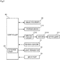
- Fig. 2 is a block diagram showing an electrical configuration of the printing apparatus 1.
- the printing apparatus 1 is an apparatus which prints a multi-color image on an elongated strip-shaped base material 9 to be printed thereon by ejecting inks from a plurality of head units 21 toward the base material 9 while transporting the base material 9. Examples of the base material 9 include paper and film.
- the printing apparatus 1 includes a transport mechanism 10, an image recorder 20, a light irradiator 30, a controller 40, and an input part 50. Of these components, at least the transport mechanism 10, the image recorder 20, and the light irradiator 30 are housed in an apparatus housing 100.
- the input part 50 accepts manipulations from a user. The user inputs various necessary pieces of information including information related to the base material 9 and the like via the input part 50.
- the transport mechanism 10 is a mechanism for transporting the base material 9 in a transport direction along the length of the base material 9.
- the transport mechanism 10 includes an unwinding roller 11, a plurality of transport rollers 12, a winding roller 13, and a tension sensor 14.
- the base material 9 is wound around the unwinding roller 11.
- Nip rollers 121 to be described later draw out the base material 9 wound around the unwinding roller 11, whereby the unwinding roller 11 rotates.
- the unwinding roller 11 has a rotary shaft provided with a powder brake 11A.
- the powder brake 11A is controlled by the controller 40 to be described later to produce brake torque of the unwinding roller 11.
- the powder brake 11A applies the brake torque to the unwinding roller 11, whereby the rotation of the unwinding roller 11 is suppressed.
- the transport rollers 12 include the nip rollers 121 to be described later.
- the base material 9 is drawn out from the unwinding roller 11, and is transported along a transport path formed by the transport rollers 12.
- Each of the transport rollers 12 rotates about a horizontal axis to guide the base material 9 downstream along the transport path.
- the transported base material 9 is wound and collected on the winding roller 13.
- the base material 9 is moved substantially horizontally under the image recorder 20 in a direction in which the head units 21 are arranged. During this movement, a recording surface of the base material 9 faces upwardly (toward the head units 21).
- the nip rollers 121 are disposed downstream from the light irradiator 30 to be described later along the transport path.
- the nip rollers 121 serve as a draw-out part for drawing out the base material 9 from the unwinding roller 11.
- the nip rollers 121 are connected to a motor 121A serving as a power source.
- the motor 121A is driven by a driving circuit 121B receiving a signal from the controller 40.
- the nip rollers 121 are rotated by driving the motor 121A.
- the nip rollers 121 rotate to transport the base material 9 while contacting the opposite surfaces of the base material 9 to hold the base material 9 therebetween. This causes the base material 9 to be drawn out from the unwinding roller 11, so that the unwinding roller 11 rotates. At this time, the powder brake 11A is caused to produce the brake torque, so that the rotation of the unwinding roller 11 is suppressed. This causes the rotation speed of the unwinding roller 11 to differ slightly from the rotation speed of the nip rollers 121 during the transport of the base material 9. As a result, tension is applied to the base material 9 to prevent slack or wrinkles in the base material 9 during the transport.
- the tension sensor 14 measures the tension applied to the base material 9 being transported.
- the tension sensor 14 includes a roller disposed between and above two horizontally arranged transport rollers 12. A downward load is imposed on the roller of the tension sensor 14 by the base material 9 running around the two transport rollers 12.
- the tension sensor 14 includes a piezoelectric element or a load cell not shown which measures the load imposed on the roller.
- the tension sensor 14 outputs an analog voltage proportional to the measured value. This analog voltage is amplified by an amplifier not shown, and the amplified analog voltage is inputted to the controller 40.
- the image recorder 20 is a mechanism for ejecting ultraviolet ray curable inks toward the base material 9 being transported by the transport mechanism 10.
- the image recorder 20 includes the four head units 21 arranged in the transport direction of the base material 9.
- the four head units 21 eject ink droplets of respective colors, i.e. C (Cyan), M (Magenta), Y (Yellow), and K (Black), which are color components of a multi-color image toward the recording surface of the base material 9.
- the head units 21 are disposed fixedly with respect to the apparatus housing 100.
- the light irradiator 30 includes a first light irradiator 31 positioned downstream from the image recorder 20 as seen in the transport direction, and a second light irradiator 32 downstream from the first light irradiator 31 as seen in the transport direction.
- the first light irradiator 31 directs light including ultraviolet rays, for example, from a plurality of LED light sources toward the recording surface of the base material 9. This places the inks on the base material 9 in a semi-cured state.
- the second light irradiator 32 directs light including ultraviolet rays, for example, from a metal halide lamp toward the recording surface of the base material 9.
- the amount of light from the second light irradiator 32 at the time of light emission is greater than the amount of light from the first light irradiator 31 at the time of light emission.
- the controller 40 is a means for controlling the operations of the components in the printing apparatus 1.
- the controller 40 is formed by a computer including an arithmetic processor 41 such as a CPU, a memory 42 such as a RAM, and a storage part 43 such as a hard disk drive. As indicated by broken lines in Fig. 1 , the controller 40 is electrically connected to the unwinding roller 11, the powder brake 11A, the winding roller 13, the tension sensor 14, the four head units 21, the first light irradiator 31, the second light irradiator 32, and the nip rollers 121 described above. The controller 40 temporarily reads a computer program P stored in the storage part 43 onto the memory 42.
- the arithmetic processor 41 performs arithmetic processing based on the computer program P, so that the controller 40 controls the operations of the aforementioned components. Thus, the printing process in the printing apparatus 1 proceeds.
- the controller 40 is an example of a tension controller according to the present invention.
- the arithmetic processor 41 performs arithmetic processing, whereby the controller 40 functions as an "acquisition part” and an “acceleration controller” according to the present invention.
- Fig. 3 shows data about information related to the base material 9.
- the type of the base material 9, the width and thickness of the base material 9, and a target tension value (referred to hereinafter as a target value) are associated with each other in the data shown in Fig. 3 .
- the target value is an ideal tension value to be provided to the base material 9 during the printing.
- the base material 9 has different expansion and contraction properties, depending on the type thereof. For this reason, the base material 9 is transported while tension having a corresponding target value is applied to the base material 9 during the transport of the base material 9. This improves printing quality independently of the type of the base material 9.
- This data may be previously stored in the storage part 43 before shipment from the factory or be inputted by a user via the input part 50, as appropriate.
- the printing apparatus 1 Upon starting the printing process, the printing apparatus 1 starts the transport of the base material 9 wound around the unwinding roller 11. At this time, the base material 9 is transported under tension. Then, inks are ejected from the head units 21 of the image recorder 20 toward the base material 9 being transported, based on a designated piece of image data. The process of transporting the base material 9 will be described below.
- Fig. 4 is a flow diagram showing an operation for the transport process in the printing apparatus 1.
- the unwinding roller 11, the nip rollers 121, and the like are at rest at the start of the transport process shown in Fig. 4 .
- the controller 40 judges whether the type of the base material 9 has been inputted via the input part 50 or not (Step S1). For the input of the type of the base material 9, a number assigned to each type or the name of each type may be inputted. If the type of the base material 9 has not yet been inputted (NO in Step S1), the controller 40 is on standby pending the input of the type of the base material 9.
- the controller 40 acquires base material information about the base material 9 corresponding to the inputted type (Step S2).
- the base material information includes the thickness and width of the base material 9 and the winding diameter of the base material 9 wound around the unwinding roller 11.
- the controller 40 acquires the thickness and width of the base material 9 corresponding to the inputted type from the data stored in the storage part 43 and shown in Fig. 3 .
- the controller 40 also computationally calculates the winding diameter of the base material 9.
- the controller 40 acquires the angular speed of the unwinding roller 11 and the transport speed of the base material 9 to calculates the winding diameter of the base material 9 with the use of these parameters.
- the controller 40 stores the calculated values of the winding diameter one by one in the storage part 43. Storing the winding diameter allows the winding diameter to be acquired even when the transport is resumed after once suspended.
- a sensor may be used to measure the winding diameter of the base material 9.
- the controller 40 judges whether the acquired base material information about the base material 9 is included in a first condition or not (Step S3).
- An example of the first condition is that "the thickness, width, and winding diameter of the base material 9 are not less than threshold values".
- the threshold values are previously set values of the thickness, width, and winding diameter.
- the threshold values are also reference values based on which the base material 9 is judged to be susceptible to expansion and contraction, and are values obtained by experiment.
- Step S3 If the base material information about the base material 9 is included in the first condition (YES in Step S3), the controller 40 judges that the expansion/contraction phenomenon of the base material 9 is less prone to occur, thereby starting the transport of the base material 9 under normal control (Step S4). On the other hand, if the base material information about the base material 9 is not included in the first condition (NO in Step S3), the controller 40 judges that the expansion/contraction phenomenon of the base material 9 is prone to occur, thereby starting the transport of the base material 9 under acceleration-varied control (Step S5).
- Fig. 5 is a graph showing the transport speed of the base material 9 under the normal control and under the acceleration-varied control.
- the normal control is control (first control) for transporting the base material 9 with a constant acceleration.
- the controller 40 controls the driving of the nip rollers 121 to start the transport of the base material 9.
- the controller 40 accelerates the rotation of the nip rollers 121 until the transport speed of the base material 9 reaches a predetermined speed.
- a plotted line for the transport speed of the base material 9 is bent at an acceleration start time t1 and at an acceleration end time t2, as indicated by the solid line in the graph of Fig. 5 . That is, the transport speed of the base material 9 changes abruptly at the acceleration start time t1 and at the acceleration end time t2. If the normal control is exercised over the base material 9 in which the expansion/contraction phenomenon is prone to occur, variations in tension of the base material 9 is increased.
- the acceleration-varied control is control (fourth control) for transporting the base material 9 with an acceleration slower than the constant acceleration used under the normal control and for transporting the base material 9 with an S-shaped acceleration.
- the nip rollers 121 are rotated with an S-shaped acceleration. That is, the acceleration of the nip rollers 121 is gradually increased and thereafter gradually decreased.
- a plotted line for the transport speed of the base material 9 is curved at the acceleration start time t1 and at an acceleration end time t3, as indicated by the broken line in the graph of Fig. 5 . In this case, the transport speed of the base material 9 changes gradually at the acceleration start time t1 and at the acceleration end time t3.
- the controller 40 starts to transport the base material 9 with an acceleration slower than the acceleration of the base material 9 used under the normal control. Because of the slower acceleration, the time required until the transport speed of the base material 9 reaches the predetermined speed, i.e. the time interval between the acceleration start time t1 and the acceleration end time t3, under the acceleration-varied control is longer than that under the normal control.
- the time interval between the times t1 and t3 under the acceleration-varied control is twice the time interval between the times t1 and t2 under the normal control in the present preferred embodiment.
- tension is applied gradually to the base material 9 drawn out from the unwinding roller 11, so that variations in tension of the base material 9 are small at the start of the transport.
- the acceleration-varied control exercised over the base material 9 in which the expansion/contraction phenomenon is prone to occur reduces variations in tension of the base material 9.
- the base material 9 has different expansion and contraction properties, depending on the type thereof, e.g. the thickness or width thereof.
- the tension applied to the base material 9 being transported is adjusted to the target value.
- the variations in tension of the base material 9 increase if the acceleration of the base material 9 changes abruptly at the start of the transport. This results in lowered print quality.
- the expansion/contraction phenomenon of the base material 9 after the start of the transport is suppressed by gradually changing the acceleration of the base material 9 at the start of the transport as in Step S5 when the base material 9 is susceptible to expansion and contraction.
- the controller 40 controls the tension of the base material 9 (Step S6). Under this control, the controller 40 drives the powder brake 11A to vary the brake torque so that the value measured by the tension sensor 14 agrees with the target value. It is not necessary that the value measured by the tension sensor 14 is in perfect agreement with the target value. For example, the value measured by the tension sensor 14 may be within ⁇ 5% of the target value.
- the controller 40 judges whether the transport speed has reached the predetermined speed after the start of the transport of the base material 9 in Step S4 or S5 or not (Step S7). If the transport speed of the base material 9 has not reached the predetermined speed (No in Step S7), the controller 40 exercises the tension control while accelerating the transport speed of the base material 9 until the predetermined speed is reached.
- Step S7 If the transport speed of the base material 9 has reached the predetermined speed (YES in Step S7), the controller 40 performs the tension adjustment process to be described later while printing by means of the image recorder 20 (Step S8). Then, the controller 40 judges whether to complete the transport of the base material 9 or not (Step S9). To complete the transport (YES in Step S9), the controller 40 completes this process. Not to complete the transport (NO in Step S9), the controller 40 performs the tension adjustment process in Step S8.
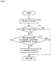
- Fig. 6 is a flow diagram showing an operation for the tension adjustment process.
- the controller 40 adjusts the tension applied to the base material 9 being transported (Step S11). Specifically, the controller 40 makes a comparison between the value measured by the tension sensor 14 and the target value. If the value measured by the tension sensor 14 is greater than the target value, the controller 40 decreases the brake torque of the powder brake 11A. If the value measured by the tension sensor 14 is less than the target value, the controller 40 increases the brake torque of the powder brake 11A. This causes the value measured by the tension sensor 14 to approach the target value.
- Step S12 judges whether the base material information about the base material 9 acquired in Step S2 is included in the first condition or not (Step S12) in the same manner as in Step S3. If the base material information about the base material 9 is not included in the first condition (NO in Step S12), i.e. if the base material 9 is susceptible to expansion and contraction, the controller 40 judges whether the variations in tension of the base material 9 being transported are less than a threshold value or not (Step S13). Specifically, if the value measured by the tension sensor 14 falls outside the ⁇ 5% range of the target value, the controller 40 judges that the variations in tension of the base material 9 being transported are not less than the threshold value.
- the controller 40 fixes the brake torque of the powder brake 11A (Step S14). This decreases the variations in tension of the base material 9 being transported.
- the controller 40 performs the process in Step S9 of Fig. 4 .
- the base material 9 is subjected to an S-shaped deceleration in the same manner as the S-shaped acceleration executed at the start of the transport, so that the transport thereof is stopped when the base material 9 is susceptible to expansion and contraction.
- this printing apparatus 1 slows down the acceleration of the base material 9 at the start of the transport to reduce changes in tension applied to the base material 9 when the base material 9 is susceptible to expansion and contraction. This suppresses the expansion/contraction phenomenon of the base material 9 transported after the start of the transport.
- the brake torque of the powder brake 11A is fixed in Step S14 of Fig. 6 .
- the brake torque may be varied to apply tension having the target value to the base material 9, thereby reducing the variations in tension of the base material 9 being transported.
- the winding diameter of the base material 9 is acquired, and a required torque of the powder brake 11A is calculated by multiplying the acquired winding diameter (radius) by the target value of the base material 9. Then, the obtained torque is defined as the brake torque of the powder brake 11A.
- the acceleration-varied control is exercised when the base material 9 is susceptible to expansion and contraction.
- the acceleration-varied control is not limited to this.
- the acceleration-varied control may be control (second control) for transporting the base material 9 with an acceleration slower than the constant acceleration used under the normal control. In this case, the base material 9 need not be transported with the S-shaped acceleration.
- the acceleration-varied control may be control (third control) for transporting the base material 9 with the S-shaped acceleration. In this case, the acceleration may be the same as the constant acceleration used under the normal control.
- the time interval between the start of acceleration and the end of acceleration may be the same as the time interval between the times t1 and t2 under the normal control with reference to Fig. 5 .
- any one of the second control, the third control, and the fourth control may be exercised as the acceleration-varied control, depending on the type of the base material 9.
- the base material information is stored in the storage part 43 in the aforementioned preferred embodiment, the thickness and width of the base material 9 may be inputted via the input part 50 each time the printing process is performed.
- the base material 9 is judged to be susceptible to expansion and contraction when all of the thickness, width, and winding diameter of the base material 9 are less than the threshold values.
- the base material 9 may be judged to be susceptible to expansion and contraction independently of the width and winding diameter of the base material 9 when the thickness of the base material 9 is less than the threshold value.
- the base material 9 may be judged to be susceptible to expansion and contraction independently of the winding diameter of the base material 9 when the thickness and width of the base material 9 are less than the threshold values.
- the normal control or the acceleration-varied control may be previously determined for each type of the base material 9 independently of the thickness or the like of the base material 9, and either the normal control or the acceleration-varied control may be exercised depending on the inputted type of the base material 9.
- the variations in tension are observed in Step S13 if the base material information about the base material 9 is not included in the first condition in Step S12.
- the variations in tension may be observed if the winding diameter of the base material 9 is less than the threshold value although the thickness and width of the base material 9 are not less than the threshold value, and the brake torque may be fixed if the variations in tension are large.
- the configuration of the details of the printing apparatus 1 may be different from that shown in the figures of the present invention.
- the components described in the aforementioned preferred embodiment and in the modifications may be combined together, as appropriate, without inconsistencies.
Landscapes
- Controlling Rewinding, Feeding, Winding, Or Abnormalities Of Webs (AREA)
- Handling Of Continuous Sheets Of Paper (AREA)
- Registering, Tensioning, Guiding Webs, And Rollers Therefor (AREA)
Abstract
Description
- The present invention relates to a printing apparatus and a printing method which transport an elongated strip-shaped base material to be printed thereon while applying tension to the base material to print on the base material.
- A printing apparatus which records an image on an elongated strip-shaped base material to be printed thereon by ejecting inks from a plurality of heads while transporting the base material has heretofore been known. For good printing results, it is necessary for the printing apparatus of this type to exercise control so that the tension applied to the base material approaches a target value, thereby transporting the base material while applying appropriate tension to the base material.
- A transport apparatus which transports a material to be recorded thereon while applying constant tension to the material is disclosed in Japanese Patent Application Laid-Open No.
2015-61807 2015-61807 2015-61807 - After a base material of the type susceptible to expansion and contraction is drawn out at the start of the transport thereof, there are cases in which variations in tension increases or the expansion/contraction phenomenon of the base material occurs when the tension applied to the base material is controlled during the subsequent transport. Large variations in tension give rise to problems such that it takes time to cause the tension of the base material to converge to the target value and such that print quality is lowered. Japanese Patent Application Laid-Open No.
2015-61807 - It is therefore an object of the present invention to provide a printing apparatus and a printing method which suppress variations in tension of a base material to be printed thereon during the transport thereof to improve the printing quality of the base material.
- To solve the aforementioned problem, a first aspect of the present invention is intended for a printing apparatus for transporting an elongated strip-shaped base material to be printed thereon while applying tension to the base material to print on the base material. The printing apparatus comprises: a roller around which a base material to be printed thereon is wound; a transport part for unwinding the base material from the roller to transport the base material; a tension controller for applying brake torque to the roller to apply tension to the base material unwound from the roller; a printing part for printing on the base material under tension; and a tension sensor for detecting the tension applied to the base material, the transport part including an acquisition part for acquiring information related to the base material, and an acceleration controller for accelerating the base material until the transport speed of the base material reaches a predetermined speed when the transport of the base material is at rest, wherein the acceleration controller exercises first control for accelerating the base material with a constant acceleration, if the information acquired by the acquisition part is included in a first condition, and wherein the acceleration controller exercises second control for accelerating the base material with an acceleration slower than the constant acceleration, third control for accelerating the base material with an S-shaped acceleration, or fourth control for accelerating the base material with an acceleration slower than the constant acceleration and for accelerating the base material with an S-shaped acceleration, if the information acquired by the acquisition part is not included in the first condition.
- A second aspect of the present invention is intended for the printing apparatus of the first aspect, wherein the information related to the base material includes the thickness of the base material; and the thickness of the base material is not less than a threshold value under the first condition.
- A third aspect of the present invention is intended for the printing apparatus of the second aspect, wherein the information related to the base material includes the width of the base material; and the width of the base material is not less than a threshold value under the first condition.
- A fourth aspect of the present invention is intended for the printing apparatus of the third aspect further comprising: a storage part for storing the type of the base material and the thickness and width of the base material in association with each other; and an input part for inputting the type of the base material, wherein the acquisition part acquires the thickness and width of the base material corresponding to the type inputted via the input part from the storage part.
- A fifth aspect of the present invention is intended for the printing apparatus of the third or fourth aspect, wherein the information related to the base material includes the winding diameter of the base material wound around the roller; and the winding diameter of the base material is not less than a threshold value under the first condition.
- A sixth aspect of the present invention is intended for the printing apparatus of any one of the first to fifth aspects, wherein after the first control, the second control, the third control, or the fourth control is exercised, the tension controller increases the brake torque of the roller if the tension detected by the tension sensor is less than a target value determined depending on the type of the base material, and decreases the brake torque of the roller if the tension detected by the tension sensor is greater than the target value.
- A seventh aspect of the present invention is intended for the printing apparatus of the sixth aspect further comprising a judging part for judging whether a varied value of the tension detected by the tension sensor is less than a threshold value or not if the information acquired by the acquisition part is not included in the first condition, wherein the tension controller fixes the brake torque of the roller if the judging part judges that the varied value is not less than the threshold value.
- An eighth aspect of the present invention is intended for the printing apparatus of the sixth aspect further comprising a judging part for judging whether a varied value of the tension detected by the tension sensor is less than a threshold value or not if the information acquired by the acquisition part is not included in the first condition, wherein the tension controller acquires the winding diameter of the base material wound around the roller to define a torque calculated from the acquired winding diameter and the target value as the brake torque of the roller if the judging part judges that the varied value is not less than the threshold value.
- A ninth aspect of the present invention is intended for a method of transporting an elongated strip-shaped base material to be printed thereon while applying tension to the base material to print on the base material through the use of a printing apparatus, the printing apparatus including a roller around which a base material to be printed thereon is wound, a transport part for unwinding the base material from the roller to transport the base material, a tension controller for applying brake torque to the roller to apply tension to the base material unwound from the roller, a printing part for printing on the base material under tension, and a tension sensor for detecting the tension applied to the base material. The method comprises the steps of: a) acquiring information related to the base material; and b) accelerating the base material until the transport speed of the base material reaches a predetermined speed, the steps a) and b) being performed when the transport of the base material is at rest, wherein first control for accelerating the base material with a constant acceleration is exercised in the step b), if the information acquired by the acquisition part is included in a first condition, and wherein second control for accelerating the base material with an acceleration slower than the constant acceleration, third control for accelerating the base material with an S-shaped acceleration, or fourth control for accelerating the base material with an acceleration slower than the constant acceleration and for accelerating the base material with an S-shaped acceleration is exercised in the step b), if the information acquired by the acquisition part is not included in the first condition.
- The first to ninth aspects of the present invention are capable of suppressing variations in tension of the base material being transported. This provides good print quality.
-
-
Fig. 1 is a diagram showing a configuration of a printing apparatus according to one preferred embodiment of the present invention; -
Fig. 2 is a block diagram showing an electrical configuration of the printing apparatus; -
Fig. 3 shows data about information related to a base material to be printed thereon; -
Fig. 4 is a flow diagram showing an operation for a transport process in the printing apparatus; -
Fig. 5 is a graph showing the transport speed of the base material under normal control and under acceleration-varied control; and -
Fig. 6 is a flow diagram showing an operation for a tension adjustment process. -
Fig. 1 is a diagram showing a configuration of aprinting apparatus 1 according to one preferred embodiment of the present invention.Fig. 2 is a block diagram showing an electrical configuration of theprinting apparatus 1. Theprinting apparatus 1 is an apparatus which prints a multi-color image on an elongated strip-shaped base material 9 to be printed thereon by ejecting inks from a plurality ofhead units 21 toward thebase material 9 while transporting thebase material 9. Examples of thebase material 9 include paper and film. - The
printing apparatus 1 includes atransport mechanism 10, animage recorder 20, alight irradiator 30, acontroller 40, and aninput part 50. Of these components, at least thetransport mechanism 10, theimage recorder 20, and thelight irradiator 30 are housed in anapparatus housing 100. Theinput part 50 accepts manipulations from a user. The user inputs various necessary pieces of information including information related to thebase material 9 and the like via theinput part 50. - The
transport mechanism 10 is a mechanism for transporting thebase material 9 in a transport direction along the length of thebase material 9. Thetransport mechanism 10 includes an unwinding roller 11, a plurality oftransport rollers 12, awinding roller 13, and atension sensor 14. - The
base material 9 is wound around the unwinding roller 11.Nip rollers 121 to be described later draw out thebase material 9 wound around the unwinding roller 11, whereby the unwinding roller 11 rotates. The unwinding roller 11 has a rotary shaft provided with apowder brake 11A. Thepowder brake 11A is controlled by thecontroller 40 to be described later to produce brake torque of the unwinding roller 11. Thepowder brake 11A applies the brake torque to the unwinding roller 11, whereby the rotation of the unwinding roller 11 is suppressed. - The
transport rollers 12 include thenip rollers 121 to be described later. Thebase material 9 is drawn out from the unwinding roller 11, and is transported along a transport path formed by thetransport rollers 12. Each of thetransport rollers 12 rotates about a horizontal axis to guide thebase material 9 downstream along the transport path. The transportedbase material 9 is wound and collected on the windingroller 13. - The
base material 9 is moved substantially horizontally under theimage recorder 20 in a direction in which thehead units 21 are arranged. During this movement, a recording surface of thebase material 9 faces upwardly (toward the head units 21). - The
nip rollers 121 are disposed downstream from thelight irradiator 30 to be described later along the transport path. Thenip rollers 121 serve as a draw-out part for drawing out thebase material 9 from the unwinding roller 11. As shown inFig. 2 , thenip rollers 121 are connected to amotor 121A serving as a power source. Themotor 121A is driven by adriving circuit 121B receiving a signal from thecontroller 40. Thenip rollers 121 are rotated by driving themotor 121A. - The
nip rollers 121 rotate to transport thebase material 9 while contacting the opposite surfaces of thebase material 9 to hold thebase material 9 therebetween. This causes thebase material 9 to be drawn out from the unwinding roller 11, so that the unwinding roller 11 rotates. At this time, thepowder brake 11A is caused to produce the brake torque, so that the rotation of the unwinding roller 11 is suppressed. This causes the rotation speed of the unwinding roller 11 to differ slightly from the rotation speed of the niprollers 121 during the transport of thebase material 9. As a result, tension is applied to thebase material 9 to prevent slack or wrinkles in thebase material 9 during the transport. - The
tension sensor 14 measures the tension applied to thebase material 9 being transported. Thetension sensor 14 includes a roller disposed between and above two horizontally arrangedtransport rollers 12. A downward load is imposed on the roller of thetension sensor 14 by thebase material 9 running around the twotransport rollers 12. Thetension sensor 14 includes a piezoelectric element or a load cell not shown which measures the load imposed on the roller. Thetension sensor 14 outputs an analog voltage proportional to the measured value. This analog voltage is amplified by an amplifier not shown, and the amplified analog voltage is inputted to thecontroller 40. - The
image recorder 20 is a mechanism for ejecting ultraviolet ray curable inks toward thebase material 9 being transported by thetransport mechanism 10. Theimage recorder 20 includes the fourhead units 21 arranged in the transport direction of thebase material 9. The fourhead units 21 eject ink droplets of respective colors, i.e. C (Cyan), M (Magenta), Y (Yellow), and K (Black), which are color components of a multi-color image toward the recording surface of thebase material 9. Thehead units 21 are disposed fixedly with respect to theapparatus housing 100. - The
light irradiator 30 includes afirst light irradiator 31 positioned downstream from theimage recorder 20 as seen in the transport direction, and asecond light irradiator 32 downstream from thefirst light irradiator 31 as seen in the transport direction. Thefirst light irradiator 31 directs light including ultraviolet rays, for example, from a plurality of LED light sources toward the recording surface of thebase material 9. This places the inks on thebase material 9 in a semi-cured state. Thesecond light irradiator 32 directs light including ultraviolet rays, for example, from a metal halide lamp toward the recording surface of thebase material 9. The amount of light from thesecond light irradiator 32 at the time of light emission is greater than the amount of light from thefirst light irradiator 31 at the time of light emission. Thus, when irradiated with light from thesecond light irradiator 32, the inks on thebase material 9 are completely cured and fixed on the recording surface of thebase material 9. - The
controller 40 is a means for controlling the operations of the components in theprinting apparatus 1. Thecontroller 40 is formed by a computer including anarithmetic processor 41 such as a CPU, amemory 42 such as a RAM, and astorage part 43 such as a hard disk drive. As indicated by broken lines inFig. 1 , thecontroller 40 is electrically connected to the unwinding roller 11, thepowder brake 11A, the windingroller 13, thetension sensor 14, the fourhead units 21, thefirst light irradiator 31, thesecond light irradiator 32, and the niprollers 121 described above. Thecontroller 40 temporarily reads a computer program P stored in thestorage part 43 onto thememory 42. Thearithmetic processor 41 performs arithmetic processing based on the computer program P, so that thecontroller 40 controls the operations of the aforementioned components. Thus, the printing process in theprinting apparatus 1 proceeds. Thecontroller 40 is an example of a tension controller according to the present invention. Thearithmetic processor 41 performs arithmetic processing, whereby thecontroller 40 functions as an "acquisition part" and an "acceleration controller" according to the present invention. - Data required for operation control, e.g. information related to the
base material 9, is stored in thestorage part 43.Fig. 3 shows data about information related to thebase material 9. The type of thebase material 9, the width and thickness of thebase material 9, and a target tension value (referred to hereinafter as a target value) are associated with each other in the data shown inFig. 3 . The target value is an ideal tension value to be provided to thebase material 9 during the printing. Thebase material 9 has different expansion and contraction properties, depending on the type thereof. For this reason, thebase material 9 is transported while tension having a corresponding target value is applied to thebase material 9 during the transport of thebase material 9. This improves printing quality independently of the type of thebase material 9. This data may be previously stored in thestorage part 43 before shipment from the factory or be inputted by a user via theinput part 50, as appropriate. - Upon starting the printing process, the
printing apparatus 1 starts the transport of thebase material 9 wound around the unwinding roller 11. At this time, thebase material 9 is transported under tension. Then, inks are ejected from thehead units 21 of theimage recorder 20 toward thebase material 9 being transported, based on a designated piece of image data. The process of transporting thebase material 9 will be described below. -
Fig. 4 is a flow diagram showing an operation for the transport process in theprinting apparatus 1. The unwinding roller 11, the niprollers 121, and the like are at rest at the start of the transport process shown inFig. 4 . - The
controller 40 judges whether the type of thebase material 9 has been inputted via theinput part 50 or not (Step S1). For the input of the type of thebase material 9, a number assigned to each type or the name of each type may be inputted. If the type of thebase material 9 has not yet been inputted (NO in Step S1), thecontroller 40 is on standby pending the input of the type of thebase material 9. - If the type of the
base material 9 has been inputted (YES in Step S1), thecontroller 40 acquires base material information about thebase material 9 corresponding to the inputted type (Step S2). The base material information includes the thickness and width of thebase material 9 and the winding diameter of thebase material 9 wound around the unwinding roller 11. - The
controller 40 acquires the thickness and width of thebase material 9 corresponding to the inputted type from the data stored in thestorage part 43 and shown inFig. 3 . Thecontroller 40 also computationally calculates the winding diameter of thebase material 9. Thecontroller 40 acquires the angular speed of the unwinding roller 11 and the transport speed of thebase material 9 to calculates the winding diameter of thebase material 9 with the use of these parameters. Thecontroller 40 stores the calculated values of the winding diameter one by one in thestorage part 43. Storing the winding diameter allows the winding diameter to be acquired even when the transport is resumed after once suspended. A sensor may be used to measure the winding diameter of thebase material 9. - The
controller 40 judges whether the acquired base material information about thebase material 9 is included in a first condition or not (Step S3). An example of the first condition is that "the thickness, width, and winding diameter of thebase material 9 are not less than threshold values". The threshold values are previously set values of the thickness, width, and winding diameter. The threshold values are also reference values based on which thebase material 9 is judged to be susceptible to expansion and contraction, and are values obtained by experiment. - If the base material information about the
base material 9 is included in the first condition (YES in Step S3), thecontroller 40 judges that the expansion/contraction phenomenon of thebase material 9 is less prone to occur, thereby starting the transport of thebase material 9 under normal control (Step S4). On the other hand, if the base material information about thebase material 9 is not included in the first condition (NO in Step S3), thecontroller 40 judges that the expansion/contraction phenomenon of thebase material 9 is prone to occur, thereby starting the transport of thebase material 9 under acceleration-varied control (Step S5). - The normal control and the acceleration-varied control will be described.
Fig. 5 is a graph showing the transport speed of thebase material 9 under the normal control and under the acceleration-varied control. - The normal control is control (first control) for transporting the
base material 9 with a constant acceleration. Thecontroller 40 controls the driving of the niprollers 121 to start the transport of thebase material 9. At this time, thecontroller 40 accelerates the rotation of the niprollers 121 until the transport speed of thebase material 9 reaches a predetermined speed. In this case, a plotted line for the transport speed of thebase material 9 is bent at an acceleration start time t1 and at an acceleration end time t2, as indicated by the solid line in the graph ofFig. 5 . That is, the transport speed of thebase material 9 changes abruptly at the acceleration start time t1 and at the acceleration end time t2. If the normal control is exercised over thebase material 9 in which the expansion/contraction phenomenon is prone to occur, variations in tension of thebase material 9 is increased. - The acceleration-varied control is control (fourth control) for transporting the
base material 9 with an acceleration slower than the constant acceleration used under the normal control and for transporting thebase material 9 with an S-shaped acceleration. Under the acceleration-varied control, the niprollers 121 are rotated with an S-shaped acceleration. That is, the acceleration of the niprollers 121 is gradually increased and thereafter gradually decreased. Thus, a plotted line for the transport speed of thebase material 9 is curved at the acceleration start time t1 and at an acceleration end time t3, as indicated by the broken line in the graph ofFig. 5 . In this case, the transport speed of thebase material 9 changes gradually at the acceleration start time t1 and at the acceleration end time t3. - The
controller 40 starts to transport thebase material 9 with an acceleration slower than the acceleration of thebase material 9 used under the normal control. Because of the slower acceleration, the time required until the transport speed of thebase material 9 reaches the predetermined speed, i.e. the time interval between the acceleration start time t1 and the acceleration end time t3, under the acceleration-varied control is longer than that under the normal control. The time interval between the times t1 and t3 under the acceleration-varied control is twice the time interval between the times t1 and t2 under the normal control in the present preferred embodiment. In this case, tension is applied gradually to thebase material 9 drawn out from the unwinding roller 11, so that variations in tension of thebase material 9 are small at the start of the transport. Thus, the acceleration-varied control exercised over thebase material 9 in which the expansion/contraction phenomenon is prone to occur reduces variations in tension of thebase material 9. - The
base material 9 has different expansion and contraction properties, depending on the type thereof, e.g. the thickness or width thereof. In a tension adjustment process to be described later, the tension applied to thebase material 9 being transported is adjusted to the target value. At this time, there is apprehension that the variations in tension of thebase material 9 increase if the acceleration of thebase material 9 changes abruptly at the start of the transport. This results in lowered print quality. To prevent this, the expansion/contraction phenomenon of thebase material 9 after the start of the transport is suppressed by gradually changing the acceleration of thebase material 9 at the start of the transport as in Step S5 when thebase material 9 is susceptible to expansion and contraction. - Referring again to the process in
Fig. 4 , thecontroller 40 controls the tension of the base material 9 (Step S6). Under this control, thecontroller 40 drives thepowder brake 11A to vary the brake torque so that the value measured by thetension sensor 14 agrees with the target value. It is not necessary that the value measured by thetension sensor 14 is in perfect agreement with the target value. For example, the value measured by thetension sensor 14 may be within ±5% of the target value. - The
controller 40 judges whether the transport speed has reached the predetermined speed after the start of the transport of thebase material 9 in Step S4 or S5 or not (Step S7). If the transport speed of thebase material 9 has not reached the predetermined speed (No in Step S7), thecontroller 40 exercises the tension control while accelerating the transport speed of thebase material 9 until the predetermined speed is reached. - If the transport speed of the
base material 9 has reached the predetermined speed (YES in Step S7), thecontroller 40 performs the tension adjustment process to be described later while printing by means of the image recorder 20 (Step S8). Then, thecontroller 40 judges whether to complete the transport of thebase material 9 or not (Step S9). To complete the transport (YES in Step S9), thecontroller 40 completes this process. Not to complete the transport (NO in Step S9), thecontroller 40 performs the tension adjustment process in Step S8. -
Fig. 6 is a flow diagram showing an operation for the tension adjustment process. Thecontroller 40 adjusts the tension applied to thebase material 9 being transported (Step S11). Specifically, thecontroller 40 makes a comparison between the value measured by thetension sensor 14 and the target value. If the value measured by thetension sensor 14 is greater than the target value, thecontroller 40 decreases the brake torque of thepowder brake 11A. If the value measured by thetension sensor 14 is less than the target value, thecontroller 40 increases the brake torque of thepowder brake 11A. This causes the value measured by thetension sensor 14 to approach the target value. - Next, the
controller 40 judges whether the base material information about thebase material 9 acquired in Step S2 is included in the first condition or not (Step S12) in the same manner as in Step S3. If the base material information about thebase material 9 is not included in the first condition (NO in Step S12), i.e. if thebase material 9 is susceptible to expansion and contraction, thecontroller 40 judges whether the variations in tension of thebase material 9 being transported are less than a threshold value or not (Step S13). Specifically, if the value measured by thetension sensor 14 falls outside the ±5% range of the target value, thecontroller 40 judges that the variations in tension of thebase material 9 being transported are not less than the threshold value. - If the variations in tension of the
base material 9 are not less than the threshold value (NO in Step S13), thecontroller 40 fixes the brake torque of thepowder brake 11A (Step S14). This decreases the variations in tension of thebase material 9 being transported. - On the other hand, if the base material information about the
base material 9 is included in the first condition (YES in Step S12) or if the variations in tension of thebase material 9 being transported are less than the threshold value (YES in Step S13), thecontroller 40 performs the process in Step S9 ofFig. 4 . - In the case of stopping the transport of the
base material 9, thebase material 9 is subjected to an S-shaped deceleration in the same manner as the S-shaped acceleration executed at the start of the transport, so that the transport thereof is stopped when thebase material 9 is susceptible to expansion and contraction. - As described above, this
printing apparatus 1 slows down the acceleration of thebase material 9 at the start of the transport to reduce changes in tension applied to thebase material 9 when thebase material 9 is susceptible to expansion and contraction. This suppresses the expansion/contraction phenomenon of thebase material 9 transported after the start of the transport. - While the main preferred embodiment according to the present invention has been described hereinabove, the present invention is not limited to the aforementioned preferred embodiment.
- In the aforementioned preferred embodiment, the brake torque of the
powder brake 11A is fixed in Step S14 ofFig. 6 . However, the brake torque may be varied to apply tension having the target value to thebase material 9, thereby reducing the variations in tension of thebase material 9 being transported. Specifically, the winding diameter of thebase material 9 is acquired, and a required torque of thepowder brake 11A is calculated by multiplying the acquired winding diameter (radius) by the target value of thebase material 9. Then, the obtained torque is defined as the brake torque of thepowder brake 11A. This applies the tension having the target value to thebase material 9. In this case, it is not necessary to acquire the value measured by thetension sensor 14. - In the aforementioned preferred embodiment, the acceleration-varied control is exercised when the
base material 9 is susceptible to expansion and contraction. However, the acceleration-varied control is not limited to this. For example, the acceleration-varied control may be control (second control) for transporting thebase material 9 with an acceleration slower than the constant acceleration used under the normal control. In this case, thebase material 9 need not be transported with the S-shaped acceleration. Alternatively, the acceleration-varied control may be control (third control) for transporting thebase material 9 with the S-shaped acceleration. In this case, the acceleration may be the same as the constant acceleration used under the normal control. In other words, the time interval between the start of acceleration and the end of acceleration may be the same as the time interval between the times t1 and t2 under the normal control with reference toFig. 5 . Further, any one of the second control, the third control, and the fourth control may be exercised as the acceleration-varied control, depending on the type of thebase material 9. - Although the base material information is stored in the
storage part 43 in the aforementioned preferred embodiment, the thickness and width of thebase material 9 may be inputted via theinput part 50 each time the printing process is performed. In the aforementioned preferred embodiment, thebase material 9 is judged to be susceptible to expansion and contraction when all of the thickness, width, and winding diameter of thebase material 9 are less than the threshold values. However, thebase material 9 may be judged to be susceptible to expansion and contraction independently of the width and winding diameter of thebase material 9 when the thickness of thebase material 9 is less than the threshold value. Alternatively, thebase material 9 may be judged to be susceptible to expansion and contraction independently of the winding diameter of thebase material 9 when the thickness and width of thebase material 9 are less than the threshold values. - Also, which control is to be exercised, the normal control or the acceleration-varied control, may be previously determined for each type of the
base material 9 independently of the thickness or the like of thebase material 9, and either the normal control or the acceleration-varied control may be exercised depending on the inputted type of thebase material 9. - In the tension adjustment process shown in
Fig. 6 , the variations in tension are observed in Step S13 if the base material information about thebase material 9 is not included in the first condition in Step S12. However, the variations in tension may be observed if the winding diameter of thebase material 9 is less than the threshold value although the thickness and width of thebase material 9 are not less than the threshold value, and the brake torque may be fixed if the variations in tension are large. - The numerical values in the aforementioned preferred embodiment are merely examples. The present invention is not limited to these values.
- The configuration of the details of the
printing apparatus 1 may be different from that shown in the figures of the present invention. The components described in the aforementioned preferred embodiment and in the modifications may be combined together, as appropriate, without inconsistencies. - While the invention has been described in detail, the foregoing description is in all aspects illustrative and not restrictive. It is understood that numerous other modifications and variations can be devised without departing from the scope of the invention.
Claims (9)
- A printing apparatus for transporting an elongated strip-shaped base material to be printed thereon while applying tension to said base material to print on said base material, said printing apparatus comprising:a roller around which a base material to be printed thereon is wound;a transport part for unwinding said base material from said roller to transport said base material;a tension controller for applying brake torque to said roller to apply tension to said base material unwound from said roller;a printing part for printing on said base material under tension; anda tension sensor for detecting the tension applied to said base material,said transport part includingan acquisition part for acquiring information related to said base material, andan acceleration controller for accelerating said base material until the transport speed of said base material reaches a predetermined speed when the transport of said base material is at rest,wherein said acceleration controller exercises first control for accelerating said base material with a constant acceleration, if the information acquired by said acquisition part is included in a first condition, andwherein said acceleration controller exercises second control for accelerating said base material with an acceleration slower than said constant acceleration, third control for accelerating said base material with an S-shaped acceleration, or fourth control for accelerating said base material with an acceleration slower than said constant acceleration and for accelerating said base material with an S-shaped acceleration, if the information acquired by said acquisition part is not included in said first condition.
- The printing apparatus according to claim 1, wherein:the information related to said base material includes the thickness of said base material; andthe thickness of said base material is not less than a threshold value under said first condition.
- The printing apparatus according to claim 2, wherein:the information related to said base material includes the width of said base material; andthe width of said base material is not less than a threshold value under said first condition.
- The printing apparatus according to claim 3, further comprising:a storage part for storing the type of said base material and the thickness and width of said base material in association with each other; andan input part for inputting the type of said base material,wherein said acquisition part acquires the thickness and width of said base material corresponding to the type inputted via said input part from said storage part.
- The printing apparatus according to claim 3 or 4, wherein:the information related to said base material includes the winding diameter of said base material wound around said roller; andthe winding diameter of said base material is not less than a threshold value under said first condition.
- The printing apparatus according to any one of claims 1 to 5, wherein
after said first control, said second control, said third control, or said fourth control is exercised, said tension controller increases the brake torque of said roller if the tension detected by said tension sensor is less than a target value determined depending on the type of said base material, and decreases the brake torque of said roller if the tension detected by said tension sensor is greater than said target value. - The printing apparatus according to claim 6, further comprising
a judging part for judging whether a varied value of the tension detected by said tension sensor is less than a threshold value or not if the information acquired by said acquisition part is not included in said first condition,
wherein said tension controller fixes the brake torque of said roller if said judging part judges that the varied value is not less than the threshold value. - The printing apparatus according to claim 6, further comprising
a judging part for judging whether a varied value of the tension detected by said tension sensor is less than a threshold value or not if the information acquired by said acquisition part is not included in said first condition,
wherein said tension controller acquires the winding diameter of said base material wound around said roller to define a torque calculated from the acquired winding diameter and said target value as the brake torque of said roller if said judging part judges that the varied value is not less than the threshold value. - A method of transporting an elongated strip-shaped base material to be printed thereon while applying tension to said base material to print on said base material through the use of a printing apparatus, said printing apparatus including a roller around which a base material to be printed thereon is wound, a transport part for unwinding said base material from said roller to transport said base material, a tension controller for applying brake torque to said roller to apply tension to said base material unwound from said roller, a printing part for printing on said base material under tension, and a tension sensor for detecting the tension applied to said base material, said method comprising the steps of:a) acquiring information related to said base material; andb) accelerating said base material until the transport speed of said base material reaches a predetermined speed,said steps a) and b) being performed when the transport of said base material is at rest,
wherein first control for accelerating said base material with a constant acceleration is exercised in said step b), if the information acquired by said acquisition part is included in a first condition, and
wherein second control for accelerating said base material with an acceleration slower than said constant acceleration, third control for accelerating said base material with an S-shaped acceleration, or fourth control for accelerating said base material with an acceleration slower than said constant acceleration and for accelerating said base material with an S-shaped acceleration is exercised in said step b), if the information acquired by said acquisition part is not included in said first condition.
Applications Claiming Priority (1)
| Application Number | Priority Date | Filing Date | Title |
|---|---|---|---|
| JP2017177580A JP2019051651A (en) | 2017-09-15 | 2017-09-15 | Printer and printing method |
Publications (2)
| Publication Number | Publication Date |
|---|---|
| EP3456543A1 true EP3456543A1 (en) | 2019-03-20 |
| EP3456543B1 EP3456543B1 (en) | 2021-04-21 |
Family
ID=63108445
Family Applications (1)
| Application Number | Title | Priority Date | Filing Date |
|---|---|---|---|
| EP18186453.9A Active EP3456543B1 (en) | 2017-09-15 | 2018-07-31 | Printing apparatus and printing method |
Country Status (2)
| Country | Link |
|---|---|
| EP (1) | EP3456543B1 (en) |
| JP (1) | JP2019051651A (en) |
Cited By (1)
| Publication number | Priority date | Publication date | Assignee | Title |
|---|---|---|---|---|
| US12629948B2 (en) | 2021-07-28 | 2026-05-19 | SCREEN Holdings Co., Ltd. | Image forming apparatus and method for controlling same |
Citations (3)
| Publication number | Priority date | Publication date | Assignee | Title |
|---|---|---|---|---|
| JP2015061807A (en) | 2015-01-08 | 2015-04-02 | セイコーエプソン株式会社 | Conveyance device for material to be recorded, and recording device |
| JP6070806B2 (en) * | 2015-10-28 | 2017-02-01 | セイコーエプソン株式会社 | Recording apparatus control method and recording apparatus |
| JP2017132191A (en) * | 2016-01-29 | 2017-08-03 | 理想科学工業株式会社 | Printing device |
Family Cites Families (9)
| Publication number | Priority date | Publication date | Assignee | Title |
|---|---|---|---|---|
| JPS62195751A (en) * | 1986-02-21 | 1987-08-28 | Hitachi Ltd | Tape transfer control device |
| JP2523542B2 (en) * | 1986-11-08 | 1996-08-14 | 株式会社リコー | Roll-shaped recording medium supply device |
| JPH01275358A (en) * | 1988-04-28 | 1989-11-06 | Toshiba Corp | Tension controller |
| JPH01321245A (en) * | 1988-06-22 | 1989-12-27 | Toshiba Corp | Rewinder controller |
| JPH08231100A (en) * | 1995-02-27 | 1996-09-10 | Mitsubishi Heavy Ind Ltd | Rolled paper accelerating method for rotary press printing machine |
| JPH08277050A (en) * | 1995-04-07 | 1996-10-22 | Shibaura Eng Works Co Ltd | Tension generating mechanism of winding device and tension generating method |
| JP4015215B2 (en) * | 1996-12-11 | 2007-11-28 | 株式会社湯山製作所 | Sheet tension adjusting method, sheet tension adjusting device and core for sheet roll |
| JP3780062B2 (en) * | 1997-05-07 | 2006-05-31 | 株式会社小森コーポレーション | Tension control method and apparatus |
| JP6447151B2 (en) * | 2015-01-14 | 2019-01-09 | 株式会社Ihi | Tension control device and transfer device |
-
2017
- 2017-09-15 JP JP2017177580A patent/JP2019051651A/en active Pending
-
2018
- 2018-07-31 EP EP18186453.9A patent/EP3456543B1/en active Active
Patent Citations (3)
| Publication number | Priority date | Publication date | Assignee | Title |
|---|---|---|---|---|
| JP2015061807A (en) | 2015-01-08 | 2015-04-02 | セイコーエプソン株式会社 | Conveyance device for material to be recorded, and recording device |
| JP6070806B2 (en) * | 2015-10-28 | 2017-02-01 | セイコーエプソン株式会社 | Recording apparatus control method and recording apparatus |
| JP2017132191A (en) * | 2016-01-29 | 2017-08-03 | 理想科学工業株式会社 | Printing device |
Cited By (1)
| Publication number | Priority date | Publication date | Assignee | Title |
|---|---|---|---|---|
| US12629948B2 (en) | 2021-07-28 | 2026-05-19 | SCREEN Holdings Co., Ltd. | Image forming apparatus and method for controlling same |
Also Published As
| Publication number | Publication date |
|---|---|
| JP2019051651A (en) | 2019-04-04 |
| EP3456543B1 (en) | 2021-04-21 |
Similar Documents
| Publication | Publication Date | Title |
|---|---|---|
| US11623462B2 (en) | Liquid ejection apparatus, winding control method, and computer readable recording medium | |
| US20110129274A1 (en) | Printing apparatus and abnormality determining method | |
| US20180037037A1 (en) | Image recording apparatus and image recording method | |
| US9387703B2 (en) | Image recording apparatus, calibration method, and image recording method | |
| US11465868B2 (en) | Transport device, recording device, and medium transport method | |
| US10946644B2 (en) | Printer device and method for generating appropriate conveyance force | |
| US8159159B2 (en) | Controlling tension in roll-based print media | |
| US11130344B2 (en) | Printing apparatus and printing method | |
| EP3078619A1 (en) | Transport apparatus, image recording apparatus and transport method | |
| US8851620B1 (en) | Image formation device and transport control method for recording medium | |
| EP3456543B1 (en) | Printing apparatus and printing method | |
| US9925809B2 (en) | Roll-up apparatus | |
| US11376876B2 (en) | Printing apparatus and method of printing | |
| US9126428B2 (en) | Mark detection method and print apparatus | |
| US20150191032A1 (en) | Roll paper conveyance control method, roll paper conveyance device, and printer | |
| JP2013147306A (en) | Conveyance device, conveyance method, and image recording apparatus | |
| US20190232635A1 (en) | Web conveying device | |
| JP5689004B2 (en) | Printer and printer control method | |
| US7537334B2 (en) | Media linefeed error compensation method | |
| JP3580882B2 (en) | Pre-recording method for long paper recording device | |
| US10421634B2 (en) | Medium feeding apparatus | |
| JPWO2020054007A1 (en) | Thermal transfer printer | |
| JP2024131763A (en) | Printing device and method for controlling printing device | |
| US6563277B1 (en) | Belt-drive-control circuit and electrophotographic device | |
| US10392216B2 (en) | Web transporting apparatus, web transporting method, image forming apparatus, and image forming method |
Legal Events
| Date | Code | Title | Description |
|---|---|---|---|
| PUAI | Public reference made under article 153(3) epc to a published international application that has entered the european phase |
Free format text: ORIGINAL CODE: 0009012 |
|
| STAA | Information on the status of an ep patent application or granted ep patent |
Free format text: STATUS: THE APPLICATION HAS BEEN PUBLISHED |
|
| AK | Designated contracting states |
Kind code of ref document: A1 Designated state(s): AL AT BE BG CH CY CZ DE DK EE ES FI FR GB GR HR HU IE IS IT LI LT LU LV MC MK MT NL NO PL PT RO RS SE SI SK SM TR |
|
| AX | Request for extension of the european patent |
Extension state: BA ME |
|
| STAA | Information on the status of an ep patent application or granted ep patent |
Free format text: STATUS: REQUEST FOR EXAMINATION WAS MADE |
|
| 17P | Request for examination filed |
Effective date: 20190919 |
|
| RBV | Designated contracting states (corrected) |
Designated state(s): AL AT BE BG CH CY CZ DE DK EE ES FI FR GB GR HR HU IE IS IT LI LT LU LV MC MK MT NL NO PL PT RO RS SE SI SK SM TR |
|
| GRAP | Despatch of communication of intention to grant a patent |
Free format text: ORIGINAL CODE: EPIDOSNIGR1 |
|
| STAA | Information on the status of an ep patent application or granted ep patent |
Free format text: STATUS: GRANT OF PATENT IS INTENDED |
|
| INTG | Intention to grant announced |
Effective date: 20210127 |
|
| RIN1 | Information on inventor provided before grant (corrected) |
Inventor name: KITAOJI, MUNEAKI Inventor name: SUEHIRO, MASAMI Inventor name: TAMURA, TOSHIO Inventor name: FUKUI, TAMIO |
|
| GRAS | Grant fee paid |
Free format text: ORIGINAL CODE: EPIDOSNIGR3 |
|
| GRAA | (expected) grant |
Free format text: ORIGINAL CODE: 0009210 |
|
| STAA | Information on the status of an ep patent application or granted ep patent |
Free format text: STATUS: THE PATENT HAS BEEN GRANTED |
|
| AK | Designated contracting states |
Kind code of ref document: B1 Designated state(s): AL AT BE BG CH CY CZ DE DK EE ES FI FR GB GR HR HU IE IS IT LI LT LU LV MC MK MT NL NO PL PT RO RS SE SI SK SM TR |
|
| REG | Reference to a national code |
Ref country code: GB Ref legal event code: FG4D |
|
| REG | Reference to a national code |
Ref country code: CH Ref legal event code: EP |
|
| REG | Reference to a national code |
Ref country code: DE Ref legal event code: R096 Ref document number: 602018015749 Country of ref document: DE |
|
| REG | Reference to a national code |
Ref country code: IE Ref legal event code: FG4D |
|
| REG | Reference to a national code |
Ref country code: AT Ref legal event code: REF Ref document number: 1384242 Country of ref document: AT Kind code of ref document: T Effective date: 20210515 |
|
| REG | Reference to a national code |
Ref country code: LT Ref legal event code: MG9D |
|
| REG | Reference to a national code |
Ref country code: AT Ref legal event code: MK05 Ref document number: 1384242 Country of ref document: AT Kind code of ref document: T Effective date: 20210421 |
|
| REG | Reference to a national code |
Ref country code: NL Ref legal event code: MP Effective date: 20210421 |
|
| PG25 | Lapsed in a contracting state [announced via postgrant information from national office to epo] |
Ref country code: LT Free format text: LAPSE BECAUSE OF FAILURE TO SUBMIT A TRANSLATION OF THE DESCRIPTION OR TO PAY THE FEE WITHIN THE PRESCRIBED TIME-LIMIT Effective date: 20210421 Ref country code: HR Free format text: LAPSE BECAUSE OF FAILURE TO SUBMIT A TRANSLATION OF THE DESCRIPTION OR TO PAY THE FEE WITHIN THE PRESCRIBED TIME-LIMIT Effective date: 20210421 Ref country code: FI Free format text: LAPSE BECAUSE OF FAILURE TO SUBMIT A TRANSLATION OF THE DESCRIPTION OR TO PAY THE FEE WITHIN THE PRESCRIBED TIME-LIMIT Effective date: 20210421 Ref country code: NL Free format text: LAPSE BECAUSE OF FAILURE TO SUBMIT A TRANSLATION OF THE DESCRIPTION OR TO PAY THE FEE WITHIN THE PRESCRIBED TIME-LIMIT Effective date: 20210421 Ref country code: BG Free format text: LAPSE BECAUSE OF FAILURE TO SUBMIT A TRANSLATION OF THE DESCRIPTION OR TO PAY THE FEE WITHIN THE PRESCRIBED TIME-LIMIT Effective date: 20210721 Ref country code: AT Free format text: LAPSE BECAUSE OF FAILURE TO SUBMIT A TRANSLATION OF THE DESCRIPTION OR TO PAY THE FEE WITHIN THE PRESCRIBED TIME-LIMIT Effective date: 20210421 |
|
| PG25 | Lapsed in a contracting state [announced via postgrant information from national office to epo] |
Ref country code: GR Free format text: LAPSE BECAUSE OF FAILURE TO SUBMIT A TRANSLATION OF THE DESCRIPTION OR TO PAY THE FEE WITHIN THE PRESCRIBED TIME-LIMIT Effective date: 20210722 Ref country code: IS Free format text: LAPSE BECAUSE OF FAILURE TO SUBMIT A TRANSLATION OF THE DESCRIPTION OR TO PAY THE FEE WITHIN THE PRESCRIBED TIME-LIMIT Effective date: 20210821 Ref country code: LV Free format text: LAPSE BECAUSE OF FAILURE TO SUBMIT A TRANSLATION OF THE DESCRIPTION OR TO PAY THE FEE WITHIN THE PRESCRIBED TIME-LIMIT Effective date: 20210421 Ref country code: PT Free format text: LAPSE BECAUSE OF FAILURE TO SUBMIT A TRANSLATION OF THE DESCRIPTION OR TO PAY THE FEE WITHIN THE PRESCRIBED TIME-LIMIT Effective date: 20210823 Ref country code: PL Free format text: LAPSE BECAUSE OF FAILURE TO SUBMIT A TRANSLATION OF THE DESCRIPTION OR TO PAY THE FEE WITHIN THE PRESCRIBED TIME-LIMIT Effective date: 20210421 Ref country code: NO Free format text: LAPSE BECAUSE OF FAILURE TO SUBMIT A TRANSLATION OF THE DESCRIPTION OR TO PAY THE FEE WITHIN THE PRESCRIBED TIME-LIMIT Effective date: 20210721 Ref country code: SE Free format text: LAPSE BECAUSE OF FAILURE TO SUBMIT A TRANSLATION OF THE DESCRIPTION OR TO PAY THE FEE WITHIN THE PRESCRIBED TIME-LIMIT Effective date: 20210421 Ref country code: RS Free format text: LAPSE BECAUSE OF FAILURE TO SUBMIT A TRANSLATION OF THE DESCRIPTION OR TO PAY THE FEE WITHIN THE PRESCRIBED TIME-LIMIT Effective date: 20210421 |
|
| REG | Reference to a national code |
Ref country code: DE Ref legal event code: R097 Ref document number: 602018015749 Country of ref document: DE |
|
| PG25 | Lapsed in a contracting state [announced via postgrant information from national office to epo] |
Ref country code: DK Free format text: LAPSE BECAUSE OF FAILURE TO SUBMIT A TRANSLATION OF THE DESCRIPTION OR TO PAY THE FEE WITHIN THE PRESCRIBED TIME-LIMIT Effective date: 20210421 Ref country code: CZ Free format text: LAPSE BECAUSE OF FAILURE TO SUBMIT A TRANSLATION OF THE DESCRIPTION OR TO PAY THE FEE WITHIN THE PRESCRIBED TIME-LIMIT Effective date: 20210421 Ref country code: RO Free format text: LAPSE BECAUSE OF FAILURE TO SUBMIT A TRANSLATION OF THE DESCRIPTION OR TO PAY THE FEE WITHIN THE PRESCRIBED TIME-LIMIT Effective date: 20210421 Ref country code: EE Free format text: LAPSE BECAUSE OF FAILURE TO SUBMIT A TRANSLATION OF THE DESCRIPTION OR TO PAY THE FEE WITHIN THE PRESCRIBED TIME-LIMIT Effective date: 20210421 Ref country code: ES Free format text: LAPSE BECAUSE OF FAILURE TO SUBMIT A TRANSLATION OF THE DESCRIPTION OR TO PAY THE FEE WITHIN THE PRESCRIBED TIME-LIMIT Effective date: 20210421 Ref country code: SM Free format text: LAPSE BECAUSE OF FAILURE TO SUBMIT A TRANSLATION OF THE DESCRIPTION OR TO PAY THE FEE WITHIN THE PRESCRIBED TIME-LIMIT Effective date: 20210421 Ref country code: SK Free format text: LAPSE BECAUSE OF FAILURE TO SUBMIT A TRANSLATION OF THE DESCRIPTION OR TO PAY THE FEE WITHIN THE PRESCRIBED TIME-LIMIT Effective date: 20210421 |
|
| PLBE | No opposition filed within time limit |
Free format text: ORIGINAL CODE: 0009261 |
|
| STAA | Information on the status of an ep patent application or granted ep patent |
Free format text: STATUS: NO OPPOSITION FILED WITHIN TIME LIMIT |
|
| REG | Reference to a national code |
Ref country code: CH Ref legal event code: PL |
|
| 26N | No opposition filed |
Effective date: 20220124 |
|
| PG25 | Lapsed in a contracting state [announced via postgrant information from national office to epo] |
Ref country code: MC Free format text: LAPSE BECAUSE OF FAILURE TO SUBMIT A TRANSLATION OF THE DESCRIPTION OR TO PAY THE FEE WITHIN THE PRESCRIBED TIME-LIMIT Effective date: 20210421 |
|
| REG | Reference to a national code |
Ref country code: BE Ref legal event code: MM Effective date: 20210731 |
|
| PG25 | Lapsed in a contracting state [announced via postgrant information from national office to epo] |
Ref country code: LI Free format text: LAPSE BECAUSE OF NON-PAYMENT OF DUE FEES Effective date: 20210731 Ref country code: CH Free format text: LAPSE BECAUSE OF NON-PAYMENT OF DUE FEES Effective date: 20210731 |
|
| PG25 | Lapsed in a contracting state [announced via postgrant information from national office to epo] |
Ref country code: IS Free format text: LAPSE BECAUSE OF FAILURE TO SUBMIT A TRANSLATION OF THE DESCRIPTION OR TO PAY THE FEE WITHIN THE PRESCRIBED TIME-LIMIT Effective date: 20210821 Ref country code: LU Free format text: LAPSE BECAUSE OF NON-PAYMENT OF DUE FEES Effective date: 20210731 Ref country code: AL Free format text: LAPSE BECAUSE OF FAILURE TO SUBMIT A TRANSLATION OF THE DESCRIPTION OR TO PAY THE FEE WITHIN THE PRESCRIBED TIME-LIMIT Effective date: 20210421 |
|
| PG25 | Lapsed in a contracting state [announced via postgrant information from national office to epo] |
Ref country code: IT Free format text: LAPSE BECAUSE OF FAILURE TO SUBMIT A TRANSLATION OF THE DESCRIPTION OR TO PAY THE FEE WITHIN THE PRESCRIBED TIME-LIMIT Effective date: 20210421 Ref country code: IE Free format text: LAPSE BECAUSE OF NON-PAYMENT OF DUE FEES Effective date: 20210731 Ref country code: BE Free format text: LAPSE BECAUSE OF NON-PAYMENT OF DUE FEES Effective date: 20210731 |
|
| P01 | Opt-out of the competence of the unified patent court (upc) registered |
Effective date: 20230515 |
|
| PG25 | Lapsed in a contracting state [announced via postgrant information from national office to epo] |
Ref country code: CY Free format text: LAPSE BECAUSE OF FAILURE TO SUBMIT A TRANSLATION OF THE DESCRIPTION OR TO PAY THE FEE WITHIN THE PRESCRIBED TIME-LIMIT Effective date: 20210421 |
|
| PG25 | Lapsed in a contracting state [announced via postgrant information from national office to epo] |
Ref country code: HU Free format text: LAPSE BECAUSE OF FAILURE TO SUBMIT A TRANSLATION OF THE DESCRIPTION OR TO PAY THE FEE WITHIN THE PRESCRIBED TIME-LIMIT; INVALID AB INITIO Effective date: 20180731 |
|
| PG25 | Lapsed in a contracting state [announced via postgrant information from national office to epo] |
Ref country code: MK Free format text: LAPSE BECAUSE OF FAILURE TO SUBMIT A TRANSLATION OF THE DESCRIPTION OR TO PAY THE FEE WITHIN THE PRESCRIBED TIME-LIMIT Effective date: 20210421 |
|
| PG25 | Lapsed in a contracting state [announced via postgrant information from national office to epo] |
Ref country code: MT Free format text: LAPSE BECAUSE OF FAILURE TO SUBMIT A TRANSLATION OF THE DESCRIPTION OR TO PAY THE FEE WITHIN THE PRESCRIBED TIME-LIMIT Effective date: 20210421 |
|
| PGFP | Annual fee paid to national office [announced via postgrant information from national office to epo] |
Ref country code: GB Payment date: 20250612 Year of fee payment: 8 |
|
| PGFP | Annual fee paid to national office [announced via postgrant information from national office to epo] |
Ref country code: FR Payment date: 20250610 Year of fee payment: 8 |
|
| PGFP | Annual fee paid to national office [announced via postgrant information from national office to epo] |
Ref country code: DE Payment date: 20250604 Year of fee payment: 8 |
|
| PG25 | Lapsed in a contracting state [announced via postgrant information from national office to epo] |
Ref country code: TR Free format text: LAPSE BECAUSE OF FAILURE TO SUBMIT A TRANSLATION OF THE DESCRIPTION OR TO PAY THE FEE WITHIN THE PRESCRIBED TIME-LIMIT Effective date: 20210421 |