EP3456490A1 - Robot control system and robot control method - Google Patents
Robot control system and robot control method Download PDFInfo
- Publication number
- EP3456490A1 EP3456490A1 EP17815186.6A EP17815186A EP3456490A1 EP 3456490 A1 EP3456490 A1 EP 3456490A1 EP 17815186 A EP17815186 A EP 17815186A EP 3456490 A1 EP3456490 A1 EP 3456490A1
- Authority
- EP
- European Patent Office
- Prior art keywords
- robot hand
- clip
- component
- robot
- inclination
- Prior art date
- Legal status (The legal status is an assumption and is not a legal conclusion. Google has not performed a legal analysis and makes no representation as to the accuracy of the status listed.)
- Withdrawn
Links
Images




Classifications
-
- B—PERFORMING OPERATIONS; TRANSPORTING
- B25—HAND TOOLS; PORTABLE POWER-DRIVEN TOOLS; MANIPULATORS
- B25J—MANIPULATORS; CHAMBERS PROVIDED WITH MANIPULATION DEVICES
- B25J9/00—Program-controlled manipulators
- B25J9/16—Program controls
- B25J9/1679—Program controls characterised by the tasks executed
- B25J9/1687—Assembly, peg and hole, palletising, straight line, weaving pattern movement
-
- B—PERFORMING OPERATIONS; TRANSPORTING
- B25—HAND TOOLS; PORTABLE POWER-DRIVEN TOOLS; MANIPULATORS
- B25J—MANIPULATORS; CHAMBERS PROVIDED WITH MANIPULATION DEVICES
- B25J13/00—Controls for manipulators
- B25J13/08—Controls for manipulators by means of sensing devices, e.g. viewing or touching devices
- B25J13/088—Controls for manipulators by means of sensing devices, e.g. viewing or touching devices with position, velocity or acceleration sensors
- B25J13/089—Determining the position of the robot with reference to its environment
-
- B—PERFORMING OPERATIONS; TRANSPORTING
- B25—HAND TOOLS; PORTABLE POWER-DRIVEN TOOLS; MANIPULATORS
- B25J—MANIPULATORS; CHAMBERS PROVIDED WITH MANIPULATION DEVICES
- B25J9/00—Program-controlled manipulators
- B25J9/16—Program controls
- B25J9/1612—Program controls characterised by the hand, wrist, grip control
-
- B—PERFORMING OPERATIONS; TRANSPORTING
- B25—HAND TOOLS; PORTABLE POWER-DRIVEN TOOLS; MANIPULATORS
- B25J—MANIPULATORS; CHAMBERS PROVIDED WITH MANIPULATION DEVICES
- B25J9/00—Program-controlled manipulators
- B25J9/16—Program controls
- B25J9/1628—Program controls characterised by the control loop
- B25J9/1638—Program controls characterised by the control loop compensation for arm bending/inertia, pay load weight/inertia
-
- B—PERFORMING OPERATIONS; TRANSPORTING
- B25—HAND TOOLS; PORTABLE POWER-DRIVEN TOOLS; MANIPULATORS
- B25J—MANIPULATORS; CHAMBERS PROVIDED WITH MANIPULATION DEVICES
- B25J9/00—Program-controlled manipulators
- B25J9/16—Program controls
- B25J9/1656—Program controls characterised by programming, planning systems for manipulators
- B25J9/1664—Program controls characterised by programming, planning systems for manipulators characterised by motion, path, trajectory planning
-
- B—PERFORMING OPERATIONS; TRANSPORTING
- B25—HAND TOOLS; PORTABLE POWER-DRIVEN TOOLS; MANIPULATORS
- B25J—MANIPULATORS; CHAMBERS PROVIDED WITH MANIPULATION DEVICES
- B25J9/00—Program-controlled manipulators
- B25J9/16—Program controls
- B25J9/1694—Program controls characterised by use of sensors other than normal servo-feedback from position, speed or acceleration sensors, perception control, multi-sensor controlled systems, sensor fusion
- B25J9/1697—Vision controlled systems
-
- G—PHYSICS
- G05—CONTROLLING; REGULATING
- G05D—SYSTEMS FOR CONTROLLING OR REGULATING NON-ELECTRIC VARIABLES
- G05D1/00—Control of position, course, altitude or attitude of land, water, air or space vehicles, e.g. using automatic pilots
- G05D1/02—Control of position or course in two dimensions
- G05D1/021—Control of position or course in two dimensions specially adapted to land vehicles
- G05D1/0231—Control of position or course in two dimensions specially adapted to land vehicles using optical position detecting means
- G05D1/0246—Control of position or course in two dimensions specially adapted to land vehicles using optical position detecting means using a video camera in combination with image processing means
- G05D1/0251—Control of position or course in two dimensions specially adapted to land vehicles using optical position detecting means using a video camera in combination with image processing means extracting 3D information from a plurality of images taken from different locations, e.g. stereo vision
-
- G—PHYSICS
- G05—CONTROLLING; REGULATING
- G05B—CONTROL OR REGULATING SYSTEMS IN GENERAL; FUNCTIONAL ELEMENTS OF SUCH SYSTEMS; MONITORING OR TESTING ARRANGEMENTS FOR SUCH SYSTEMS OR ELEMENTS
- G05B2219/00—Program-control systems
- G05B2219/30—Nc systems
- G05B2219/39—Robotics, robotics to robotics hand
- G05B2219/39176—Compensation deflection arm
-
- G—PHYSICS
- G05—CONTROLLING; REGULATING
- G05B—CONTROL OR REGULATING SYSTEMS IN GENERAL; FUNCTIONAL ELEMENTS OF SUCH SYSTEMS; MONITORING OR TESTING ARRANGEMENTS FOR SUCH SYSTEMS OR ELEMENTS
- G05B2219/00—Program-control systems
- G05B2219/30—Nc systems
- G05B2219/40—Robotics, robotics mapping to robotics vision
- G05B2219/40583—Detect relative position or orientation between gripper and currently handled object
-
- G—PHYSICS
- G05—CONTROLLING; REGULATING
- G05B—CONTROL OR REGULATING SYSTEMS IN GENERAL; FUNCTIONAL ELEMENTS OF SUCH SYSTEMS; MONITORING OR TESTING ARRANGEMENTS FOR SUCH SYSTEMS OR ELEMENTS
- G05B2219/00—Program-control systems
- G05B2219/30—Nc systems
- G05B2219/40—Robotics, robotics mapping to robotics vision
- G05B2219/40601—Reference sensors
-
- G—PHYSICS
- G05—CONTROLLING; REGULATING
- G05B—CONTROL OR REGULATING SYSTEMS IN GENERAL; FUNCTIONAL ELEMENTS OF SUCH SYSTEMS; MONITORING OR TESTING ARRANGEMENTS FOR SUCH SYSTEMS OR ELEMENTS
- G05B2219/00—Program-control systems
- G05B2219/30—Nc systems
- G05B2219/40—Robotics, robotics mapping to robotics vision
- G05B2219/40623—Track position of end effector by laser beam
Definitions
- the present invention relates to a robot control system and a robot control method.
- the clip When manufacturing the structural body of aircraft components, such as the fuselage and wings of an aircraft, there are cases that other components, such as clips, for example, are attached to long materials such as stringers that constitute the structural body.
- the clip has an inverted T-shape cross section, and the bottom surface is a flat surface.
- the bottom surface of the clip is placed on the upper surface of the stringer, a through-hole is formed by a drill in a state in which both are in contact with each other, and subsequently, the stringer and the clip are fastened by a rivet.
- Patent Document 1 it is disclosed that, since large machines, especially large machines with operating ranges that exceed 15 feet, cause errors resulting from thermal expansion and mechanical misalignment between shafts, an interferometer laser tracker or 3D position sensor is used to measure the position of a retroreflector attached to an end effector such as a machine head, and the machine is moved to the correct position prior to machining.
- Patent Document 2 techniques are disclosed for moving, in a manufacturing environment such as an assembly line, objects such as the wings of aircraft that are complicated in shape and difficult to support while accurately maintaining their posture.
- components such as clips have manufacturing tolerances, and there are deviations in the size and shape of each manufactured component.
- a robot hand grasps a part such as a clip, it is not always possible to grasp the same place each time. That is, the positional relationship and the angle of the clip held by the robot hand are not constant with respect to the robot hand for each operation. For this reason, even in a case where the position of the robot hand can be accurately detected by using the detection unit of the robot or the laser tracker and reflector, as a result of moving the clip or the like onto the stringer, there are cases where the clip cannot be placed at a desired location on the stringer.
- the present invention is made in light of the foregoing circumstances, and has an object of providing a robot control system and a robot control method capable of placing a component grasped by a robot hand at a correct location on another member.
- a robot control system including: a robot hand configured to grasp a component; an imaging unit configured to image the component grasped by the robot hand; a calculation unit configured to calculate, based on an imaging result of the component imaged by the imaging unit, a position of the component or an inclination of the component; and a robot control unit configured to control, based on the position of the component or the inclination of the component calculated by the calculation unit, the robot hand to adjust a position or an inclination of the robot hand and move the component to another member.
- the component grasped by the robot hand is imaged by the imaging unit, and the position or the inclination of the component is calculated based on the imaging result.
- the position or the inclination of the robot hand is adjusted based on the calculated position or inclination of the component.
- the robot hand can move the grasped component to another member, and the component grasped by the robot hand is correctly placed on the other member.
- the robot control system may further include a position detection unit configured to detect a position or an inclination of the robot hand and a position or an inclination of the imaging unit, and the robot control unit may control, based on the position or inclination of the robot hand and the position or inclination of the imaging unit detected by the position detection unit, the position or the inclination of the robot hand with respect to the imaging unit.
- a position detection unit configured to detect a position or an inclination of the robot hand and a position or an inclination of the imaging unit
- the robot control unit may control, based on the position or inclination of the robot hand and the position or inclination of the imaging unit detected by the position detection unit, the position or the inclination of the robot hand with respect to the imaging unit.
- the position or the inclination of the robot hand and the position or the inclination of the imaging unit are detected by the position detection unit, and the position or the inclination of the robot hand with respect to the imaging unit is controlled based on the detected position or inclination of the robot hand and the position or inclination of the imaging unit.
- the imaging unit may be a stereoscopic camera, and may be configured to image a bottom surface of the component.
- the imaging unit is a stereoscopic camera and images the bottom surface, the position or the inclination of the component is detected based on the bottom surface of the component imaged by the imaging unit.
- the robot control unit may be configured to control the robot hand to place the bottom surface of the component on an upper surface of the another member.
- the component is moved to another member by the robot hand, and the bottom surface of the component is placed on the upper surface of another member.
- a robot control method includes a step of imaging a component grasped by a robot hand configured to grasp a component; a step of calculating, based on an imaging result of the imaged component, a position of the component or an inclination of the component; a step of adjusting, based on the calculated position of the component or the inclination of the component, a position or an inclination of the robot hand; and a step of controlling the robot hand to move the component to another member.
- the components grasped by the robot hand can be accurately arranged on other members.
- a robot control system 1 is used when assembling structural bodies of aircraft components, such as the fuselage or main wing of an aircraft.
- the fuselage, main wing, and the like of the aircraft components are constructed by combining a structural body and a thin plate member (skin), and the structural body is formed by combining multiple structural components.
- the multiple structural components include stringers, clips, shear ties, frames, and the like.
- a clip 31 is given as an example of a component
- an elongated stringer 32 is given as an example of another member on which a component is arranged
- a case in which the clip 31 is arranged and fastened with respect to the stringer 32 will be described, but the present invention is not limited to these examples.
- the application of the present invention is not limited to aircraft components, and the present invention is also applicable to the assembly of other components.
- the clip 31 has an inverted T-shape transverse cross section, and includes a horizontal plate 31a and an orthogonal plate 31b provided in an orthogonal direction from the middle of the horizontal plate 31a.
- the bottom surface of the horizontal plate 31a of the clip 31 is placed on the upper surface of the stringer 32, and subsequently, the clip 31 and the stringer 32 are fastened by rivets.
- the orthogonal plate 31b can be grasped by the robot hand 12.
- the stringer 32 has, for example, a Z-shaped cross section, an L-shaped cross section, or the like.
- the robot control system 1 includes a robot 2, a camera 3 that is a stereoscopic camera, a position detection device 4, a control device 5, or the like.
- the control device 5 is realized by a computer or the like that executes a program.
- the robot 2 includes a robot main body portion 11, a robot hand 12, or the like.
- the robot main body portion 11 supports the robot hand 12, and can adjust the position and the inclination of the robot hand 12.
- the robot hand 12 can grasp a clip 31 to be installed on the stringer 32, and can release the grasp of the clip 31.
- the robot 2 grasps a clip 31 placed in a predetermined component storage area, moves the grasped clip 31 to the stringer 32, and subsequently places the grasped clip 31 on the stringer 32.
- the camera 3 for example, is a stereoscopic camera, and is capable of 3-dimensionally imaging an imaged target. Data relating to the imaging result imaged and acquired by the camera 3 is transmitted from the camera 3 to the calculation unit 16. The camera 3 is placed at a location where the bottom surface of the clip 31 grasped by the robot hand 12 can be imaged, for example, and the orientation of the lens is adjusted.
- the position detection device 4 includes, for example, a laser tracker 13, a reflector 14 installed in the robot hand 12, a reflector 15 installed in the camera 3, and the like.
- the laser tracker 13 irradiates laser light to the reflectors 14, 15, and receives laser light reflected by the reflectors 14, 15.
- the laser tracker 13 can acquire the 3-dimensional position of the reflectors 14, 15 from which the laser light was reflected. As illustrated in FIG. 1 , by having three reflectors 14,15 installed in each of the robot hand 12 or the camera 3, in addition to the 3-dimensional position of the robot hand 12, the inclination can also be calculated.
- the control device 5 includes a calculation unit 16, a robot control unit 17, and the like.
- the calculation unit 16 calculates coordinate information for the clip 31 that serves as the imaging target, and calculates the position and the inclination of the clip 31 with respect to the camera 3.
- the robot control unit 17 Based on the 3-dimensional position acquired by the laser tracker 13, the robot control unit 17 adjusts the position of the robot hand 12 with respect to the camera 3, and moves the robot hand 12 to a fixed imaging position.
- the robot control unit 17 adjusts the position or the inclination of the robot hand 12. Further, the robot control unit 17 controls the robot hand 12 to move the clip 31 grasped by the robot hand 12 to the stringer 32 based on the movement path.
- the robot hand 12 grasps the orthogonal plate 31b of the clip 31 placed in the predetermined component storage area (Step S1), and the robot hand 12 moves the clip 31 by driving of the robot main body portion 11.
- the clip 31 is moved within the imaging range of the camera 3 (Step S2).
- the laser tracker 13 is irradiating the laser light, and acquires the 3-dimensional position of the reflectors 14, 15 that reflect the laser light. Based on the 3-dimensional position of the reflector 14 installed in the robot hand 12 and the reflector 15 installed in the camera 3, the position and the inclination of the robot hand 12 and the camera 3 are acquired (Step S3).
- the robot control unit 17 adjusts the position and the inclination of the robot hand 12 with respect to the camera 3 (Step S4).
- the robot hand 12 is moved to the fixed imaging position, and the robot hand 12 is inclined at a predetermined inclination at the fixed imaging position.
- Step S5 the camera 3 images the clip 31 grasped by the robot hand 12 (Step S5).
- Data relating to the imaging result imaged and acquired by the camera 3 is transmitted from the camera 3 to the calculation unit 16.
- Step S6 coordinate information for the clip 31 that serves as the imaging target is calculated by the calculation unit 16 based on the data acquired by the camera 3, and the position and the inclination of the clip 31 with respect to the camera 3 are calculated based on the coordinate information of the clip 31 (Step S6).
- Step S7 the calculated position and inclination of the clip 31 are compared with a reference position or a reference inclination stored in memory in advance (Step S7).
- a shifted grasp direction and a shift amount with respect to the reference position, as well as an inclination orientation and an inclination amount, are acquired for the clip 31 in the fixed imaging position.
- Step S8 the movement path via which the robot hand 12 moves the clip 31 to the stringer 32 is corrected.
- the position and the angle of the robot hand 12 are adjusted such that the clip 31 grasped by the robot hand 12 is accurately arranged on the stringer 32.
- the robot hand 12 moves the clip 31 to the stringer 32 along the corrected movement path (Step S9).
- the robot hand 12 can move the grasped clip 31 to the stringer 32, adjust the position and the angle of the clip 31 grasped by the robot hand 12, and accurately place the clip 31 on the stringer 32.
- the position or the inclination of the robot hand 12 may first be adjusted by the robot control unit 17 based on the acquired shifted grasp direction and the shift amount and the inclination orientation and the inclination amount of the clip 31. At this time, the position or the inclination of the robot hand 12 is adjusted such that the clip 31 becomes the same as the reference position or reference inclination stored in memory in advance.
- the robot hand 12 may move the clip 31 to the stringer 32 along the predetermined movement path.
- the robot hand 12 can move the grasped clip 31 to the stringer 32, and the clip 31 grasped by the robot hand 12 is accurately placed on the stringer 32.
- the position and the angle of the clip 31 are adjusted by the robot.
- the clip 31 grasped by the robot hand 12 can be arranged at an accurate position on the stringer 32.
- the inclination of the robot hand 12 is adjusted by the robot control unit 17 based on the position and angle of the clip 31 calculated based on the imaging result of the camera 3.
- the robot control unit 17 controls the robot control unit 17 based on the position and angle of the clip 31 calculated based on the imaging result of the camera 3.
- FIG. 3B by adjusting the inclination of the robot hand 12 such that the bottom surface of the clip 31 is parallel to the upper surface of the stringer 32, no positional deviation occurs when the robot hand 12 releases its grasp of the clip 31.
- the clip 31 can be appropriately arranged on the stringer 32. Also, as illustrated in FIG. 4 , in the case that the robot hand 12 grasps the clip 31 at the original grasping position, in a case where the robot hand 12 is moved such that the distance between the robot hand 12 and the stringer 32 is a predetermined distance (in the example illustrated in FIG. 4 , the interval L between the reflector 14 and the bottom surface of the clip 31), the clip 31 can be appropriately arranged on the stringer 32. Also, as illustrated in FIG. 4 , in the case that the robot hand 12 grasps the clip 31 at the original grasping position, in a case where the robot hand 12 is moved such that the distance between the robot hand 12 and the stringer 32 is a predetermined distance (in the example illustrated in FIG. 4 , the interval L between the reflector 14 and the bottom surface of the clip 31), the clip 31 can be appropriately arranged on the stringer 32. Also, as illustrated in FIG.
- the clip 31 can be appropriately arranged on the stringer 32.
- the robot hand 12 grasps the clip 31, in a case that the clip 31 is grasped at an inclination different than the original inclination (for example, the horizontal direction), the inclination of the clip 31 with respect to the robot hand 12 cannot be ascertained according to the methods of the related art. For this reason, when the robot hand 12 is moved on a predetermined movement path, the position of the clip 31 on the stringer 32 may become a position further away from the stringer 32, or the clip 31 may tilt.
- the original inclination for example, the horizontal direction
- the position of the robot hand 12 is adjusted by the robot control unit 17 based on the position of the clip 31 calculated based on the imaging result of the camera 3.
- the position of the robot hand 12 is adjusted such that the bottom surface of the clip 31 becomes parallel to the upper surface of the stringer 32, and the stringer 32 and the clip 31 properly contact each other.
- the angle of the robot hand 12 is adjusted by the robot control unit 17 based on the angle of the clip 31 calculated based on the imaging result of the camera 3.
- the inclination of the robot hand 12 is adjusted such that the bottom surface of the clip 31 becomes parallel to the upper surface of the stringer 32, and the stringer 32 and the clip 31 properly contact each other.
- the clip 31 can be accurately positioned with respect to the stringer 32, and accurate hole-drilling can be performed.
- the clip 31 can be arranged at an accurate position with respect to the stringer 32.
- hole drilling can be performed to create an accurate circular shape without causing positional deviation.
Landscapes
- Engineering & Computer Science (AREA)
- Robotics (AREA)
- Mechanical Engineering (AREA)
- Physics & Mathematics (AREA)
- Computer Vision & Pattern Recognition (AREA)
- Aviation & Aerospace Engineering (AREA)
- Multimedia (AREA)
- Electromagnetism (AREA)
- Radar, Positioning & Navigation (AREA)
- Remote Sensing (AREA)
- General Physics & Mathematics (AREA)
- Automation & Control Theory (AREA)
- Health & Medical Sciences (AREA)
- General Health & Medical Sciences (AREA)
- Orthopedic Medicine & Surgery (AREA)
- Human Computer Interaction (AREA)
- Manipulator (AREA)
Abstract
Description
- The present invention relates to a robot control system and a robot control method.
- When manufacturing the structural body of aircraft components, such as the fuselage and wings of an aircraft, there are cases that other components, such as clips, for example, are attached to long materials such as stringers that constitute the structural body. For example, the clip has an inverted T-shape cross section, and the bottom surface is a flat surface. The bottom surface of the clip is placed on the upper surface of the stringer, a through-hole is formed by a drill in a state in which both are in contact with each other, and subsequently, the stringer and the clip are fastened by a rivet.
- In Patent Document 1 described below, it is disclosed that, since large machines, especially large machines with operating ranges that exceed 15 feet, cause errors resulting from thermal expansion and mechanical misalignment between shafts, an interferometer laser tracker or 3D position sensor is used to measure the position of a retroreflector attached to an end effector such as a machine head, and the machine is moved to the correct position prior to machining. In addition, in
Patent Document 2 described below, techniques are disclosed for moving, in a manufacturing environment such as an assembly line, objects such as the wings of aircraft that are complicated in shape and difficult to support while accurately maintaining their posture. -
- Patent Document 1:
JP 2000-511824 T - Patent Document 2:
JP 2015-42436 A - In cases that a robot having a robot hand grasps a component such as the above-described clip, places the clip or the like on a stringer, and subsequently performs a fastening operation on both, it is possible to save labor in comparison to manual work by operators. In this case, by detecting the position or the inclination of the robot hand with a detection unit of the robot main body, or detecting a reflector installed in the robot hand by a laser tracker, the position or the inclination of the robot hand can be detected.
- By contrast, in practice, components such as clips have manufacturing tolerances, and there are deviations in the size and shape of each manufactured component. In addition, when a robot hand grasps a part such as a clip, it is not always possible to grasp the same place each time. That is, the positional relationship and the angle of the clip held by the robot hand are not constant with respect to the robot hand for each operation. For this reason, even in a case where the position of the robot hand can be accurately detected by using the detection unit of the robot or the laser tracker and reflector, as a result of moving the clip or the like onto the stringer, there are cases where the clip cannot be placed at a desired location on the stringer.
- The present invention is made in light of the foregoing circumstances, and has an object of providing a robot control system and a robot control method capable of placing a component grasped by a robot hand at a correct location on another member.
- A robot control system according to a first aspect of the present invention is provided with a robot control system including: a robot hand configured to grasp a component; an imaging unit configured to image the component grasped by the robot hand; a calculation unit configured to calculate, based on an imaging result of the component imaged by the imaging unit, a position of the component or an inclination of the component; and a robot control unit configured to control, based on the position of the component or the inclination of the component calculated by the calculation unit, the robot hand to adjust a position or an inclination of the robot hand and move the component to another member.
- According to this configuration, the component grasped by the robot hand is imaged by the imaging unit, and the position or the inclination of the component is calculated based on the imaging result. Next, the position or the inclination of the robot hand is adjusted based on the calculated position or inclination of the component. Then, in a state in which the adjustment result is applied, the robot hand can move the grasped component to another member, and the component grasped by the robot hand is correctly placed on the other member.
- In the above-described first aspect, the robot control system may further include a position detection unit configured to detect a position or an inclination of the robot hand and a position or an inclination of the imaging unit, and the robot control unit may control, based on the position or inclination of the robot hand and the position or inclination of the imaging unit detected by the position detection unit, the position or the inclination of the robot hand with respect to the imaging unit.
- According to this configuration, the position or the inclination of the robot hand and the position or the inclination of the imaging unit are detected by the position detection unit, and the position or the inclination of the robot hand with respect to the imaging unit is controlled based on the detected position or inclination of the robot hand and the position or inclination of the imaging unit.
- In the above-described first aspect, the imaging unit may be a stereoscopic camera, and may be configured to image a bottom surface of the component.
- According to this configuration, since the imaging unit is a stereoscopic camera and images the bottom surface, the position or the inclination of the component is detected based on the bottom surface of the component imaged by the imaging unit.
- In the above-described first aspect, the robot control unit may be configured to control the robot hand to place the bottom surface of the component on an upper surface of the another member.
- According to this configuration, the component is moved to another member by the robot hand, and the bottom surface of the component is placed on the upper surface of another member.
- A robot control method according to a second aspect of the present invention includes a step of imaging a component grasped by a robot hand configured to grasp a component; a step of calculating, based on an imaging result of the imaged component, a position of the component or an inclination of the component; a step of adjusting, based on the calculated position of the component or the inclination of the component, a position or an inclination of the robot hand; and a step of controlling the robot hand to move the component to another member.
- According to the present invention, as the position or the inclination of the robot hand is adjusted based on the position or the inclination of the imaged component, the components grasped by the robot hand can be accurately arranged on other members.
-
-
FIG. 1 is a schematic configuration diagram illustrating a robot control system according to an embodiment of the present invention. -
FIG. 2 is a flowchart illustrating a control method of a robot hand using the robot control system according to an embodiment of the present invention. -
FIG. 3 is a front view illustrating a robot hand of a robot control system according to an embodiment of the present invention. -
FIG. 4 is a front view illustrating a robot hand of a robot control system according to an embodiment of the present invention. -
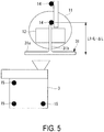
FIG. 5 is a front view illustrating a robot hand and a camera of a robot control system according to an embodiment of the present invention. -
FIG. 6 is a front view illustrating a robot hand of a robot control system according to an embodiment of the present invention. -
FIG. 7 is a side view illustrating a robot hand of a robot control system according to an embodiment of the present invention. -
FIG. 8 is a side view illustrating a robot hand and a camera of a robot control system according to an embodiment of the present invention. -
FIG. 9 is a side view illustrating a robot hand of a robot control system according to an embodiment of the present invention. -
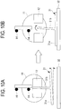
FIG. 10A and FIG. 10B are front views illustrating a robot hand of a robot control system of the related art. -
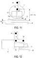
FIG. 11 is a front view illustrating a robot hand of a robot control system of the related art. -
FIG. 12 is a side view illustrating a robot hand of a robot control system of the related art. - A robot control system 1 according to an embodiment of the present invention is used when assembling structural bodies of aircraft components, such as the fuselage or main wing of an aircraft. The fuselage, main wing, and the like of the aircraft components are constructed by combining a structural body and a thin plate member (skin), and the structural body is formed by combining multiple structural components. The multiple structural components include stringers, clips, shear ties, frames, and the like.
- In the following description, a
clip 31 is given as an example of a component, anelongated stringer 32 is given as an example of another member on which a component is arranged, and a case in which theclip 31 is arranged and fastened with respect to thestringer 32 will be described, but the present invention is not limited to these examples. In addition, the application of the present invention is not limited to aircraft components, and the present invention is also applicable to the assembly of other components. - The
clip 31 has an inverted T-shape transverse cross section, and includes ahorizontal plate 31a and anorthogonal plate 31b provided in an orthogonal direction from the middle of thehorizontal plate 31a. The bottom surface of thehorizontal plate 31a of theclip 31 is placed on the upper surface of thestringer 32, and subsequently, theclip 31 and thestringer 32 are fastened by rivets. As illustrated inFIG. 1 , theorthogonal plate 31b can be grasped by therobot hand 12. Thestringer 32 has, for example, a Z-shaped cross section, an L-shaped cross section, or the like. - As illustrated in
FIG. 1 , the robot control system 1 includes arobot 2, acamera 3 that is a stereoscopic camera, aposition detection device 4, acontrol device 5, or the like. Thecontrol device 5 is realized by a computer or the like that executes a program. - The
robot 2 includes a robotmain body portion 11, arobot hand 12, or the like. The robotmain body portion 11 supports therobot hand 12, and can adjust the position and the inclination of therobot hand 12. Therobot hand 12 can grasp aclip 31 to be installed on thestringer 32, and can release the grasp of theclip 31. Therobot 2 grasps aclip 31 placed in a predetermined component storage area, moves the graspedclip 31 to thestringer 32, and subsequently places the graspedclip 31 on thestringer 32. - The
camera 3, for example, is a stereoscopic camera, and is capable of 3-dimensionally imaging an imaged target. Data relating to the imaging result imaged and acquired by thecamera 3 is transmitted from thecamera 3 to thecalculation unit 16. Thecamera 3 is placed at a location where the bottom surface of theclip 31 grasped by therobot hand 12 can be imaged, for example, and the orientation of the lens is adjusted. - The
position detection device 4 includes, for example, alaser tracker 13, areflector 14 installed in therobot hand 12, areflector 15 installed in thecamera 3, and the like. - The
laser tracker 13 irradiates laser light to thereflectors reflectors laser tracker 13 can acquire the 3-dimensional position of thereflectors FIG. 1 , by having threereflectors robot hand 12 or thecamera 3, in addition to the 3-dimensional position of therobot hand 12, the inclination can also be calculated. - The
control device 5 includes acalculation unit 16, arobot control unit 17, and the like. - Based on the data acquired by the
camera 3, thecalculation unit 16 calculates coordinate information for theclip 31 that serves as the imaging target, and calculates the position and the inclination of theclip 31 with respect to thecamera 3. - Based on the 3-dimensional position acquired by the
laser tracker 13, therobot control unit 17 adjusts the position of therobot hand 12 with respect to thecamera 3, and moves therobot hand 12 to a fixed imaging position. - In addition, based on the position or the inclination of the
robot hand 12 with respect to thecamera 3 as calculated by thecalculation unit 16, therobot control unit 17 adjusts the position or the inclination of therobot hand 12. Further, therobot control unit 17 controls therobot hand 12 to move theclip 31 grasped by therobot hand 12 to thestringer 32 based on the movement path. - Next, a control method of the
robot hand 12 using the robot control system 1 according to the present embodiment will be described with reference toFIG. 2 . - First, the
robot hand 12 grasps theorthogonal plate 31b of theclip 31 placed in the predetermined component storage area (Step S1), and therobot hand 12 moves theclip 31 by driving of the robotmain body portion 11. Theclip 31 is moved within the imaging range of the camera 3 (Step S2). - At this time, the
laser tracker 13 is irradiating the laser light, and acquires the 3-dimensional position of thereflectors reflector 14 installed in therobot hand 12 and thereflector 15 installed in thecamera 3, the position and the inclination of therobot hand 12 and thecamera 3 are acquired (Step S3). - Then, based on the 3-dimensional position acquired by the
laser tracker 13, therobot control unit 17 adjusts the position and the inclination of therobot hand 12 with respect to the camera 3 (Step S4). At this time, therobot hand 12 is moved to the fixed imaging position, and therobot hand 12 is inclined at a predetermined inclination at the fixed imaging position. By using thelaser tracker 13 and thereflectors robot hand 12 can be accurately adjusted. - Next, the
camera 3 images theclip 31 grasped by the robot hand 12 (Step S5). Data relating to the imaging result imaged and acquired by thecamera 3 is transmitted from thecamera 3 to thecalculation unit 16. - Subsequently, coordinate information for the
clip 31 that serves as the imaging target is calculated by thecalculation unit 16 based on the data acquired by thecamera 3, and the position and the inclination of theclip 31 with respect to thecamera 3 are calculated based on the coordinate information of the clip 31 (Step S6). - Next, the calculated position and inclination of the
clip 31 are compared with a reference position or a reference inclination stored in memory in advance (Step S7). As a result of the comparison, a shifted grasp direction and a shift amount with respect to the reference position, as well as an inclination orientation and an inclination amount, are acquired for theclip 31 in the fixed imaging position. - Then, based on the acquired shifted grasp direction and the shift amount and the inclination orientation and the inclination amount of the
clip 31, the movement path via which therobot hand 12 moves theclip 31 to thestringer 32 is corrected (Step S8). In the movement path, the position and the angle of therobot hand 12 are adjusted such that theclip 31 grasped by therobot hand 12 is accurately arranged on thestringer 32. - Thereafter, the
robot hand 12 moves theclip 31 to thestringer 32 along the corrected movement path (Step S9). In this way, therobot hand 12 can move the graspedclip 31 to thestringer 32, adjust the position and the angle of theclip 31 grasped by therobot hand 12, and accurately place theclip 31 on thestringer 32. - It should be noted that, as described above, instead of correcting the movement path, the position or the inclination of the
robot hand 12 may first be adjusted by therobot control unit 17 based on the acquired shifted grasp direction and the shift amount and the inclination orientation and the inclination amount of theclip 31. At this time, the position or the inclination of therobot hand 12 is adjusted such that theclip 31 becomes the same as the reference position or reference inclination stored in memory in advance. - Then, after the position or the inclination of the
robot hand 12 is adjusted, therobot hand 12 may move theclip 31 to thestringer 32 along the predetermined movement path. In this case as well, therobot hand 12 can move the graspedclip 31 to thestringer 32, and theclip 31 grasped by therobot hand 12 is accurately placed on thestringer 32. - As described above, according to the present embodiment, even in cases that components such as the
clip 31 have manufacturing tolerances and there are deviations in the size and shape of each manufactured component, or in cases that the positional relationship and angle of theclip 31 grasped by therobot hand 12 are not constant with respect to therobot hand 12 for each operation, the position and the angle of theclip 31 are adjusted by the robot. As a result, theclip 31 grasped by therobot hand 12 can be arranged at an accurate position on thestringer 32. - For example, as illustrated in
FIG. 10A and FIG. 10B , in cases that the angle of theorthogonal plate 31b with respect to thehorizontal plate 31a of theclip 31 is not an accurate 90° due to manufacturing tolerance, the angle of thehorizontal plate 31a with respect to therobot hand 12 cannot be ascertained according to the methods of the related art. For this reason, after moving theclip 31 on the predetermined movement path, as illustrated inFIG. 10A , in cases that the bottom surface of theclip 31 is inclined with respect to the upper surface of thestringer 32, positional deviation occurs when therobot hand 12 releases its grasp of theclip 31, as illustrated inFIG. 10B . - By contrast, in the case of the present embodiment, as illustrated in
FIG. 3A , the inclination of therobot hand 12 is adjusted by therobot control unit 17 based on the position and angle of theclip 31 calculated based on the imaging result of thecamera 3. At this time, as illustrated inFIG. 3B , by adjusting the inclination of therobot hand 12 such that the bottom surface of theclip 31 is parallel to the upper surface of thestringer 32, no positional deviation occurs when therobot hand 12 releases its grasp of theclip 31. - In addition, as illustrated in
FIG. 4 , in the case that therobot hand 12 grasps theclip 31 at the original grasping position, in a case where therobot hand 12 is moved such that the distance between therobot hand 12 and thestringer 32 is a predetermined distance (in the example illustrated inFIG. 4 , the interval L between thereflector 14 and the bottom surface of the clip 31), theclip 31 can be appropriately arranged on thestringer 32. Also, as illustrated inFIG. 7 , in the case that therobot hand 12 grasps theclip 31 at the original grasping angle (for example, in the horizontal direction), in a case where therobot hand 12 is moved such that the angle formed by therobot hand 12 and thestringer 32 becomes a predetermined angle (for example, 0°), theclip 31 can be appropriately arranged on thestringer 32. - By contrast, as illustrated in
FIG. 11 , when therobot hand 12 grasps theclip 31, in a case that a position different than the original grasping position is grasped (in the example illustrated inFIG. 11 , the interval L1 (= L - ΔL) between thereflector 14 and the bottom surface of the clip 31), the position of theclip 31 with respect to therobot hand 12 cannot be ascertained according to the methods of the related art. For this reason, when therobot hand 12 is moved on a predetermined movement path, a ΔL occurs in the space between the upper surface of thestringer 32 and the bottom surface of theclip 31. - In addition, as illustrated in
FIG. 12 , when therobot hand 12 grasps theclip 31, in a case that theclip 31 is grasped at an inclination different than the original inclination (for example, the horizontal direction), the inclination of theclip 31 with respect to therobot hand 12 cannot be ascertained according to the methods of the related art. For this reason, when therobot hand 12 is moved on a predetermined movement path, the position of theclip 31 on thestringer 32 may become a position further away from thestringer 32, or theclip 31 may tilt. - As described above, in cases that there is a gap between the
clip 31 and thestringer 32, and they are inclined relative to each other, when drilling holes for rivets in both theclip 31 and thestringer 32, problems arise in which the position of the hole of theclip 31 shifts with respect to thestringer 32, or the shape of the hole becomes elliptical. In addition, on the contrary, in a case that the bottom surface of theclip 31 is moved to a position lower than the upper surface of thestringer 32, a problem arises in which theclip 31 is pushed too far against thestringer 32. - In contrast, in the case of the present embodiment, as illustrated in
FIG. 5 , after the position of theclip 31 is detected by thecamera 3, as illustrated inFIG. 6 , the position of therobot hand 12 is adjusted by therobot control unit 17 based on the position of theclip 31 calculated based on the imaging result of thecamera 3. The position of therobot hand 12 is adjusted such that the bottom surface of theclip 31 becomes parallel to the upper surface of thestringer 32, and thestringer 32 and theclip 31 properly contact each other. - In addition, in the case of the present embodiment, as illustrated in
FIG. 8 , after the position of theclip 31 is detected by the camera 3 (ΔL 1 ≠ ΔL 2), as illustrated inFIG. 9 , the angle of therobot hand 12 is adjusted by therobot control unit 17 based on the angle of theclip 31 calculated based on the imaging result of thecamera 3. The inclination of therobot hand 12 is adjusted such that the bottom surface of theclip 31 becomes parallel to the upper surface of thestringer 32, and thestringer 32 and theclip 31 properly contact each other. As a result, theclip 31 can be accurately positioned with respect to thestringer 32, and accurate hole-drilling can be performed. - As described above, according to the present embodiment, the
clip 31 can be arranged at an accurate position with respect to thestringer 32. In addition, in a case that hole-drilling is simultaneously performed for both theclip 31 and thestringer 32, hole drilling can be performed to create an accurate circular shape without causing positional deviation. -
- 1 Robot control system
- 2 Robot
- 3 Camera
- 4 Position detection device
- 5 Control device
- 11 Robot main body portion
- 12 Robot hand
- 13 Laser tracker
- 14 Reflector
- 15 Reflector
- 16 Calculation unit
- 17 Robot control unit
- 31 Clip
- 31a Horizontal plate
- 31b Orthogonal plate
Claims (5)
- A robot control system comprising:a robot hand configured to grasp a component;an imaging unit configured to image the component grasped by the robot hand;a calculation unit configured to calculate, based on an imaging result of the component imaged by the imaging unit, a position of the component or an inclination of the component; anda robot control unit configured to control, based on the position of the component or the inclination of the component calculated by the calculation unit, the robot hand to adjust a position or an inclination of the robot hand and move the component to another member.
- The robot control system according to claim 1, further comprising
a position detection unit configured to detect a position or an inclination of the robot hand and a position or an inclination of the imaging unit,
wherein the robot control unit controls, based on the position or inclination of the robot hand and the position or inclination of the imaging unit detected by the position detection unit, the position or the inclination of the robot hand with respect to the imaging unit. - The robot control system according to claim 1 or 2, wherein the imaging unit is a stereoscopic camera, and is configured to image a bottom surface of the component.
- The robot control system according to any one of claims 1 to 3, wherein the robot control unit is configured to control the robot hand to place a bottom surface of the component on an upper surface of the another member.
- A robot control method comprising:a step of imaging a component grasped by a robot hand configured to grasp a component;a step of calculating, based on an imaging result of the imaged component, a position of the component or an inclination of the component;a step of adjusting, based on the calculated position of the component or the inclination of the component, a position or an inclination of the robot hand; anda step of controlling the robot hand to move the component to another member.
Applications Claiming Priority (2)
| Application Number | Priority Date | Filing Date | Title |
|---|---|---|---|
| JP2016121681A JP6665040B2 (en) | 2016-06-20 | 2016-06-20 | Robot control system and robot control method |
| PCT/JP2017/021248 WO2017221717A1 (en) | 2016-06-20 | 2017-06-08 | Robot control system and robot control method |
Publications (2)
| Publication Number | Publication Date |
|---|---|
| EP3456490A1 true EP3456490A1 (en) | 2019-03-20 |
| EP3456490A4 EP3456490A4 (en) | 2019-07-10 |
Family
ID=60784218
Family Applications (1)
| Application Number | Title | Priority Date | Filing Date |
|---|---|---|---|
| EP17815186.6A Withdrawn EP3456490A4 (en) | 2016-06-20 | 2017-06-08 | ROBOT CONTROL SYSTEM AND ROBOT CONTROL METHOD |
Country Status (7)
| Country | Link |
|---|---|
| US (1) | US11780091B2 (en) |
| EP (1) | EP3456490A4 (en) |
| JP (1) | JP6665040B2 (en) |
| CN (1) | CN109311169A (en) |
| BR (1) | BR112018075268A2 (en) |
| CA (1) | CA3026771C (en) |
| WO (1) | WO2017221717A1 (en) |
Families Citing this family (14)
| Publication number | Priority date | Publication date | Assignee | Title |
|---|---|---|---|---|
| JP6457005B2 (en) * | 2017-03-30 | 2019-01-23 | 本田技研工業株式会社 | Position estimation method and gripping method |
| JP6676030B2 (en) * | 2017-11-20 | 2020-04-08 | 株式会社安川電機 | Grasping system, learning device, gripping method, and model manufacturing method |
| CN108877770B (en) * | 2018-05-31 | 2020-01-07 | 北京百度网讯科技有限公司 | Method, apparatus and system for testing intelligent voice devices |
| JP2020085596A (en) | 2018-11-21 | 2020-06-04 | 三菱重工業株式会社 | Position measuring system and position measuring method |
| CN109658413B (en) * | 2018-12-12 | 2022-08-09 | 达闼机器人股份有限公司 | Method for detecting grabbing position of robot target object |
| CN119658725A (en) * | 2019-04-12 | 2025-03-21 | 株式会社尼康 | Robot system and control method for robot system |
| JP7296252B2 (en) * | 2019-06-03 | 2023-06-22 | 三菱重工業株式会社 | Robot control system and method |
| JP7481829B2 (en) * | 2019-11-11 | 2024-05-13 | 株式会社Subaru | Assembly Equipment |
| TWI739536B (en) * | 2020-07-31 | 2021-09-11 | 創璟應用整合有限公司 | Robotic arm system for real-time correction of clamping coordinates |
| CA3199771A1 (en) * | 2020-10-29 | 2022-05-05 | Berkshire Grey Operating Company, Inc. | Systems and methods for automated packaging and processing for shipping with object pose analysis |
| WO2022155882A1 (en) * | 2021-01-22 | 2022-07-28 | Abb Schweiz Ag | Assembling apparatus, assembling method and computer readable storage medium |
| CN120187566A (en) * | 2022-11-07 | 2025-06-20 | 株式会社尼康 | Position measurement system and position measurement method |
| US20240262638A1 (en) * | 2023-02-02 | 2024-08-08 | The Boeing Company | Pick-and-place system and method |
| CN116442247B (en) * | 2023-06-14 | 2023-11-10 | 中国电子科技集团公司第二十八研究所 | Control method of intelligent square cabin drilling and riveting system with cooperation of multiple robots |
Family Cites Families (22)
| Publication number | Priority date | Publication date | Assignee | Title |
|---|---|---|---|---|
| JPS63115205A (en) * | 1986-11-01 | 1988-05-19 | Fanuc Ltd | Robot controller |
| JP2786225B2 (en) | 1989-02-01 | 1998-08-13 | 株式会社日立製作所 | Industrial robot control method and apparatus |
| JPH085021B2 (en) * | 1990-02-01 | 1996-01-24 | 川崎重工業株式会社 | Workpiece positioning method |
| US5380978A (en) * | 1991-07-12 | 1995-01-10 | Pryor; Timothy R. | Method and apparatus for assembly of car bodies and other 3-dimensional objects |
| JPH0755427A (en) * | 1993-08-12 | 1995-03-03 | Nec Corp | Lead position detector |
| AU3294197A (en) | 1996-06-06 | 1998-01-05 | Boeing Company, The | Method for improving the accuracy of machines |
| JP2000511824A (en) | 1997-04-01 | 2000-09-12 | コーニンクレッカ フィリップス エレクトロニクス エヌ ヴィ | Separation device provided with cyclone chamber having centrifugal unit and vacuum cleaner provided with this separation device |
| SE0001312D0 (en) | 2000-04-10 | 2000-04-10 | Abb Ab | Industrial robot |
| IL158117A0 (en) * | 2001-03-26 | 2004-03-28 | Lb Medical Gmbh | Method and device system for removing material or for working material |
| JP2003231078A (en) * | 2002-02-14 | 2003-08-19 | Denso Wave Inc | Robot arm position control method and robot apparatus |
| US7233841B2 (en) * | 2002-04-19 | 2007-06-19 | Applied Materials, Inc. | Vision system |
| JP4174342B2 (en) * | 2003-02-19 | 2008-10-29 | ファナック株式会社 | Work transfer device |
| US8290618B2 (en) * | 2007-03-05 | 2012-10-16 | CNOS Automations Software GmbH | Determining positions |
| JP2008279549A (en) * | 2007-05-10 | 2008-11-20 | Honda Motor Co Ltd | Work transfer system and work transfer method |
| US20110317879A1 (en) | 2009-02-17 | 2011-12-29 | Absolute Robotics Limited | Measurement of Positional Information for a Robot Arm |
| JP5310130B2 (en) * | 2009-03-11 | 2013-10-09 | オムロン株式会社 | Display method of recognition result by three-dimensional visual sensor and three-dimensional visual sensor |
| FI20105732A0 (en) * | 2010-06-24 | 2010-06-24 | Zenrobotics Oy | Procedure for selecting physical objects in a robotic system |
| US9969131B2 (en) * | 2011-06-22 | 2018-05-15 | The Boeing Company | Automated ply layup system |
| US8843236B2 (en) * | 2012-03-15 | 2014-09-23 | GM Global Technology Operations LLC | Method and system for training a robot using human-assisted task demonstration |
| US9745081B2 (en) | 2013-07-12 | 2017-08-29 | The Boeing Company | Apparatus and method for moving a structure in a manufacturing environment |
| JP6427972B2 (en) * | 2014-06-12 | 2018-11-28 | セイコーエプソン株式会社 | Robot, robot system and control device |
| DE102014018912A1 (en) | 2014-12-17 | 2015-06-18 | Daimler Ag | Device and method for determining the position of an end effector of a robot |
-
2016
- 2016-06-20 JP JP2016121681A patent/JP6665040B2/en active Active
-
2017
- 2017-06-08 CA CA3026771A patent/CA3026771C/en active Active
- 2017-06-08 WO PCT/JP2017/021248 patent/WO2017221717A1/en not_active Ceased
- 2017-06-08 BR BR112018075268-1A patent/BR112018075268A2/en not_active Application Discontinuation
- 2017-06-08 EP EP17815186.6A patent/EP3456490A4/en not_active Withdrawn
- 2017-06-08 US US16/304,976 patent/US11780091B2/en active Active
- 2017-06-08 CN CN201780034909.0A patent/CN109311169A/en active Pending
Also Published As
| Publication number | Publication date |
|---|---|
| CA3026771C (en) | 2020-11-10 |
| US11780091B2 (en) | 2023-10-10 |
| CN109311169A (en) | 2019-02-05 |
| EP3456490A4 (en) | 2019-07-10 |
| BR112018075268A2 (en) | 2019-03-12 |
| US20200171665A1 (en) | 2020-06-04 |
| JP6665040B2 (en) | 2020-03-13 |
| JP2017226023A (en) | 2017-12-28 |
| CA3026771A1 (en) | 2017-12-28 |
| WO2017221717A1 (en) | 2017-12-28 |
Similar Documents
| Publication | Publication Date | Title |
|---|---|---|
| US11780091B2 (en) | Robot control system and robot control method | |
| US10286556B2 (en) | Method and apparatus for compliant robotic end-effector | |
| Frommknecht et al. | Multi-sensor measurement system for robotic drilling | |
| CN107867409B (en) | System and method for controlling motion of a mobile robotic assembly | |
| JP5321532B2 (en) | Robot calibration apparatus and calibration method | |
| KR102271941B1 (en) | Automated machining head with vision and procedure | |
| US10556350B2 (en) | Assembly body manufacturing device and assembly body manufacturing method | |
| JP6900290B2 (en) | Robot system | |
| US20180065204A1 (en) | Welding process | |
| JP6563271B2 (en) | Assembly manufacturing apparatus and assembly manufacturing method | |
| KR102099549B1 (en) | Assembly body manufacturing device and assembly body manufacturing method | |
| CN107530843B (en) | Assembly manufacturing device and assembly manufacturing method | |
| US20210299861A1 (en) | Control system and control method | |
| JP6150251B2 (en) | Aircraft inspection system | |
| JP6565367B2 (en) | Position correction system | |
| US20260027721A1 (en) | Method for automated docking of two parts comprising servo-control with profilometers | |
| JP6319901B2 (en) | Vehicle accuracy evaluation system | |
| JP2011102767A (en) | Non-contact type position/attitude measuring method, non-contact type position/attitude measuring device, and semiconductor mounting device equipped with the non-contact type position/attitude measuring device | |
| JP2018015834A (en) | Method for moving robot arm | |
| Filonov et al. | Laser measuring system for tool and surface relative positioning when robotic processing | |
| CN113020756B (en) | Laser module verification platform, system and method | |
| US20230302651A1 (en) | Target detection method and detection device including calibration function |
Legal Events
| Date | Code | Title | Description |
|---|---|---|---|
| STAA | Information on the status of an ep patent application or granted ep patent |
Free format text: STATUS: THE INTERNATIONAL PUBLICATION HAS BEEN MADE |
|
| PUAI | Public reference made under article 153(3) epc to a published international application that has entered the european phase |
Free format text: ORIGINAL CODE: 0009012 |
|
| STAA | Information on the status of an ep patent application or granted ep patent |
Free format text: STATUS: REQUEST FOR EXAMINATION WAS MADE |
|
| 17P | Request for examination filed |
Effective date: 20181210 |
|
| AK | Designated contracting states |
Kind code of ref document: A1 Designated state(s): AL AT BE BG CH CY CZ DE DK EE ES FI FR GB GR HR HU IE IS IT LI LT LU LV MC MK MT NL NO PL PT RO RS SE SI SK SM TR |
|
| AX | Request for extension of the european patent |
Extension state: BA ME |
|
| A4 | Supplementary search report drawn up and despatched |
Effective date: 20190607 |
|
| RIC1 | Information provided on ipc code assigned before grant |
Ipc: B25J 9/16 20060101ALI20190603BHEP Ipc: B25J 13/08 20060101AFI20190603BHEP |
|
| DAV | Request for validation of the european patent (deleted) | ||
| DAX | Request for extension of the european patent (deleted) | ||
| STAA | Information on the status of an ep patent application or granted ep patent |
Free format text: STATUS: EXAMINATION IS IN PROGRESS |
|
| 17Q | First examination report despatched |
Effective date: 20210701 |
|
| STAA | Information on the status of an ep patent application or granted ep patent |
Free format text: STATUS: THE APPLICATION HAS BEEN WITHDRAWN |
|
| 18W | Application withdrawn |
Effective date: 20210729 |