EP3456399A1 - Filter skid with tilting mechanism - Google Patents
Filter skid with tilting mechanism Download PDFInfo
- Publication number
- EP3456399A1 EP3456399A1 EP17001566.3A EP17001566A EP3456399A1 EP 3456399 A1 EP3456399 A1 EP 3456399A1 EP 17001566 A EP17001566 A EP 17001566A EP 3456399 A1 EP3456399 A1 EP 3456399A1
- Authority
- EP
- European Patent Office
- Prior art keywords
- filter element
- orientation
- filtration
- tilting
- fluid
- Prior art date
- Legal status (The legal status is an assumption and is not a legal conclusion. Google has not performed a legal analysis and makes no representation as to the accuracy of the status listed.)
- Granted
Links
Images




Classifications
-
- B—PERFORMING OPERATIONS; TRANSPORTING
- B01—PHYSICAL OR CHEMICAL PROCESSES OR APPARATUS IN GENERAL
- B01D—SEPARATION
- B01D33/00—Filters with filtering elements which move during the filtering operation
- B01D33/80—Accessories
- B01D33/802—Device for changing the inclination of the filtering element
-
- B—PERFORMING OPERATIONS; TRANSPORTING
- B01—PHYSICAL OR CHEMICAL PROCESSES OR APPARATUS IN GENERAL
- B01D—SEPARATION
- B01D29/00—Filters with filtering elements stationary during filtration, e.g. pressure or suction filters, not covered by groups B01D24/00 - B01D27/00; Filtering elements therefor
- B01D29/96—Filters with filtering elements stationary during filtration, e.g. pressure or suction filters, not covered by groups B01D24/00 - B01D27/00; Filtering elements therefor in which the filtering elements are moved between filtering operations; Particular measures for removing or replacing the filtering elements; Transport systems for filters
- B01D29/965—Device for changing the inclination of the filtering element
-
- B—PERFORMING OPERATIONS; TRANSPORTING
- B01—PHYSICAL OR CHEMICAL PROCESSES OR APPARATUS IN GENERAL
- B01D—SEPARATION
- B01D29/00—Filters with filtering elements stationary during filtration, e.g. pressure or suction filters, not covered by groups B01D24/00 - B01D27/00; Filtering elements therefor
- B01D29/50—Filters with filtering elements stationary during filtration, e.g. pressure or suction filters, not covered by groups B01D24/00 - B01D27/00; Filtering elements therefor with multiple filtering elements, characterised by their mutual disposition
-
- B—PERFORMING OPERATIONS; TRANSPORTING
- B01—PHYSICAL OR CHEMICAL PROCESSES OR APPARATUS IN GENERAL
- B01D—SEPARATION
- B01D29/00—Filters with filtering elements stationary during filtration, e.g. pressure or suction filters, not covered by groups B01D24/00 - B01D27/00; Filtering elements therefor
- B01D29/50—Filters with filtering elements stationary during filtration, e.g. pressure or suction filters, not covered by groups B01D24/00 - B01D27/00; Filtering elements therefor with multiple filtering elements, characterised by their mutual disposition
- B01D29/52—Filters with filtering elements stationary during filtration, e.g. pressure or suction filters, not covered by groups B01D24/00 - B01D27/00; Filtering elements therefor with multiple filtering elements, characterised by their mutual disposition in parallel connection
-
- B—PERFORMING OPERATIONS; TRANSPORTING
- B01—PHYSICAL OR CHEMICAL PROCESSES OR APPARATUS IN GENERAL
- B01D—SEPARATION
- B01D29/00—Filters with filtering elements stationary during filtration, e.g. pressure or suction filters, not covered by groups B01D24/00 - B01D27/00; Filtering elements therefor
- B01D29/50—Filters with filtering elements stationary during filtration, e.g. pressure or suction filters, not covered by groups B01D24/00 - B01D27/00; Filtering elements therefor with multiple filtering elements, characterised by their mutual disposition
- B01D29/56—Filters with filtering elements stationary during filtration, e.g. pressure or suction filters, not covered by groups B01D24/00 - B01D27/00; Filtering elements therefor with multiple filtering elements, characterised by their mutual disposition in series connection
-
- B—PERFORMING OPERATIONS; TRANSPORTING
- B01—PHYSICAL OR CHEMICAL PROCESSES OR APPARATUS IN GENERAL
- B01D—SEPARATION
- B01D33/00—Filters with filtering elements which move during the filtering operation
- B01D33/80—Accessories
- B01D33/804—Accessories integrally combined with devices for controlling the filtration
-
- B—PERFORMING OPERATIONS; TRANSPORTING
- B01—PHYSICAL OR CHEMICAL PROCESSES OR APPARATUS IN GENERAL
- B01D—SEPARATION
- B01D35/00—Filtering devices having features not specifically covered by groups B01D24/00 - B01D33/00, or for applications not specifically covered by groups B01D24/00 - B01D33/00; Auxiliary devices for filtration; Filter housing constructions
- B01D35/14—Safety devices specially adapted for filtration; Devices for indicating clogging
- B01D35/157—Flow control valves: Damping or calibrated passages
- B01D35/1573—Flow control valves
-
- B—PERFORMING OPERATIONS; TRANSPORTING
- B01—PHYSICAL OR CHEMICAL PROCESSES OR APPARATUS IN GENERAL
- B01D—SEPARATION
- B01D63/00—Apparatus in general for separation processes using semi-permeable membranes
- B01D63/02—Hollow fibre modules
- B01D63/04—Hollow fibre modules comprising multiple hollow fibre assemblies
- B01D63/046—Hollow fibre modules comprising multiple hollow fibre assemblies in separate housings
-
- B—PERFORMING OPERATIONS; TRANSPORTING
- B01—PHYSICAL OR CHEMICAL PROCESSES OR APPARATUS IN GENERAL
- B01D—SEPARATION
- B01D2313/00—Details relating to membrane modules or apparatus
- B01D2313/06—External membrane module supporting or fixing means
-
- B—PERFORMING OPERATIONS; TRANSPORTING
- B01—PHYSICAL OR CHEMICAL PROCESSES OR APPARATUS IN GENERAL
- B01D—SEPARATION
- B01D2313/00—Details relating to membrane modules or apparatus
- B01D2313/48—Mechanisms for switching between regular separation operations and washing
Definitions
- the present application relates to a filtration system and a corresponding filtration method for filtering of a fluid.
- preparation operations may comprise preparing a filtration system, testing the filtration system and cleaning the filtration system.
- Preparing the filtration system may include operations like mounting filter elements to the filtrations system.
- the filtration system may be pressurised to ensure that the filtration system is leak-proof in order to avoid that the fluid may leak from the filtration system.
- cleaning of the filtration system is performed with suitable cleaning fluids.
- the actual filtration process may start. After the fluid has been filtered by the filtration system, the filtered liquid is recovered from the filtration system. Afterwards, the filtration system need to be cleaned and drained again.
- WO 2013/187947 A1 discloses a support container for a bioreactor which can be tilted by various angles, including 90 °.
- a locking pin engages with a corresponding hole in a rotatable collar and allows tilting and fixing the container in the tilted position in various angles. The locking can be done manually.
- a motor and a controller for the motor which allows for automatic tilting of the support container.
- US 9,242,193 B2 discloses a filter holder which holds several filter discs next to each other in a stacked configuration.
- the filter holder has a holder arm which can be held in an upright space-saving vertical configuration which allows the venting of the filter discs.
- the holder arm can be tilted down by 90 ° in a horizontal position by means of a tilting mechanism which is manually operated by a gear box. In the horizontal configuration an ergonomic loading position is achieved in which an operator can easily check the status of the filter discs or remove and replace the filter discs.
- the holder arm can be tilted about a horizontal tilt axis to assume different intermediate positions between the horizontal and vertical configurations.
- US 9,616,365 B2 is a further variation of the filter holder known from US 9,242,193 B2 .
- US 9,616,365 B2 discloses a filter holder which comprises several filter cradles into which stacks of filter discs can be inserted.
- the filter cradles are accommodated in a carousel which can be rotated via a rotor about a rotation axis.
- the carousel as a whole can be tilted from a vertical service position for filtration operation in a horizontal indexing position in which a user can exchange the filter discs or otherwise manipulate the filter discs in an ergonomic fashion at waist height of the user.
- DE 32 40 102 A1 discloses a filter housing accommodating several flat filter elements wherein the filter housing is rotatable around two pins which are each carried by a separate bearing. By means of the two pins which are driven by a drive unit the filter housing can be tilted from a vertical position to a horizontal position in which solid residues can be removed from the filter elements.
- EP 1 671 710 B1 discloses a suction and filtration device with a filter housing which can be tilted about a hinge axis from the vertical position into a horizontal position.
- a safety belt fixes the filter housing in the tilted position wherein the filtered material can be discharged into a bag.
- US 9,636,609 B2 discloses a filtration system with a tiltable filtration unit, electronic means for measuring a degree of filtration and for generating a signal when a predetermined degree of filtration has been achieved, filter tilting means for tilting a filter from a first orientation relative to a horizontal plane to a second orientation relative to the horizontal plane.
- the filter tilting means is operable to tilt the filter in response to the signal from the electronic means.
- the electronic means may measure a volume or level of fluid in the pre-filtration chamber and/or a volume or level of fluid in the post-filtration chamber of the filtration unit. Alternatively, the electronic means may measure a time elapsed, or a weight or mass of fluid in one or the other of the chambers.
- the filter tilting means automatically tilts the filter in response to the signal from the electronic means without requiring manual intervention from an operator.
- the filter is tilted relative to the base or housing of the filter system which remains stationary.
- the filter tilting means may comprise an electric motor, such as a servo motor, and/or a mechanical motor, an electric field actuator or an electromechanical screw. Multiple resilient means or actuator springs can be used for more effective and controlled tilting.
- a filtration system comprises:
- the main flow direction of the fluid corresponds to a direction of how the fluid mainly flows through the at least one filter element during a filtration process and/or pre- and post-filtration operations, e.g. testing the filtration system, cleaning the filtration system and draining the filtration system.
- the fluid may have a flow direction different to the main flow direction.
- the main flow orientation may be substantially parallel to an imaginary main flow axis of the at least one filter element. Due to the tilting of the at least one filter element, the orientation of the main flow direction and correspondingly the orientation of the main flow axis may change.
- the orientation of the main flow direction and correspondingly the orientation of the main flow axis may change with respect to a first axis being parallel to a force of gravity and to a horizontal plane being perpendicular to the force of gravity.
- the at least one filter element may be advantageously positioned for carrying out the filtration process and/or pre-and post-filtration operations.
- the supply unit may comprise a pump unit configured to pump the fluid to the at least one filter element.
- the pump unit may be connectable to a fluid supply and configured to pump the fluid from the fluid supply to the at least one filter element.
- the fluid supply may be part of the supply unit. Alternatively, the fluid supply may be separated from the supply unit.
- the fluid supply may be connected to the pump with a suitable connection member.
- the connection member may comprise a pipeline, wherein the pipeline may be provided as a flexible or solid pipeline.
- the control unit may be further configured to control supplying and/or evacuating the fluid to/from the at least one filter element and to control tilting of the at least one filter element dependent on the filtration process and/or the pre-and post-filtration operations.
- the filtration unit is fluidly connected to the main unit with a flexible connection.
- the flexible connection allows a flexible arrangement of the filtration unit with respect to the main unit. For example, it is possible to position the main unit in different angles with respect to the filtration unit in a closed and controlled manner without compromising the sterility of the system.
- the filtration unit comprises a tilting frame configured to carry the at least one filter element, the tilting frame being tiltable around the tilting axis.
- the tilting frame may comprise at least one support member configured to carry the at least one filter element.
- the at least one support member may be rigidly connected with the tilting frame.
- the tilting frame may comprise a conduit system and the at least one filter element is connectable to the conduit system.
- the conduit system and the at least one filter element connected to the conduit system are tilted.
- the orientation of the main flow direction is changed.
- the filtration unit may comprise a main frame configured to support the tilting frame, the tilting frame being configured to be tiltable with respect to the main frame.
- a bearing may connect the tilting frame to the main frame and the bearing axis of the bearing may correspond to the tilting axis.
- the bearing may comprise two ball bearings connecting the main frame with the tilting frame, wherein the tilting axis may correspond to an axis connecting the two ball bearings so that the tilting frame is tiltable around the tilting axis.
- the main frame may have two opposing support elements. The support elements may extend horizontally and parallel to each other so that the support elements may generate a plane which is parallel to the horizontal plane and/or corresponds to the horizontal plane.
- the ball bearings may be provided at the support members so that the ball bearings are arranged opposite to each other. In other words, each of the ball bearings is associated to a different support element.
- the tilting frame may be arranged between the ball bearings and/or the support elements. Hence, the tilting frame is stably connected to the main frame and twisting of the tilting frame during tilting of the tilting frame is reduced.
- the filtration unit may comprise an actuator configured to tilt the tilting frame around the tilting axis.
- the actuator may be arranged between the tilting frame and the main frame.
- the actuator may be an electromechanical, pneumatic or hydraulic actuator.
- the filtration unit may comprise at least two actuators.
- the at least two actuators may be arranged opposite to each other, having the same effective direction.
- the at least two actuators may be provided at the outer edges of the tilting frame and the main frame. Since the effective directions of the at least two actuators are the same, the tilting frame can be tilted steadily around the tilting axis.
- the control unit is configured to tilt the at least one filter element around the tilting axis to change the orientation of the main flow direction between a first orientation and a second orientation.
- the first orientation may be a horizontal orientation being parallel to the horizontal plane.
- the horizontal orientation may be perpendicular to the first axis, the first axis being parallel to the force of gravity.
- the second orientation may be a vertical orientation which is perpendicular to the horizontal orientation and/or the horizontal plane.
- the vertical orientation may be parallel to the first axis being parallel to the force of gravity.
- the at least one filter element may be tilted so that the orientation of the main flow direction has a certain tilting angle.
- the tilting angle may be the angle between the horizontal plane and the orientation of the main flow direction. That is, the tilting angle may be 0° when the main flow direction is in the horizontal orientation and parallel to the horizontal plane. Furthermore, the tilting angle may be 90° when the main flow direction is in the vertical orientation and/or when the main flow direction is perpendicular to the horizontal plane. However, the tilting angle may also be greater or smaller than 90°. Consequently, the at least one filter element can be tilted around the tilting axis, thereby changing the orientation of the main flow direction, so that at least one filter element can be arranged in a position being beneficial for the filtration process and/or pre- and post-filtration operations.
- control unit is configured, for a test phase and/or for a recovery phase and/or for a draining phase, to tilt the at least one filter element around the tilting axis to change the orientation of the main flow direction into the first orientation.
- gravity can be used to support said phases.
- control unit may be further configured, for a filtration phase, to tilt the at least one filter element around the tilting axis to change the orientation of the main flow direction into an orientation between the first orientation and the second orientation.
- the tilting angle may be between 0° and 90°.
- the orientation of the main flow direction may be between the horizontal orientation and the vertical orientation.
- control unit may be configured to control an inlet valve and an outlet with, the inlet valve and the outlet valve being associated to the at least one filter element.
- the control unit may control the inlet valve and the outlet valve in such a manner that the fluid can be supplied and/or evacuated from/to the at least one filter element.
- the at least one filter element may comprise a first filter element and a second filter element.
- the control unit may be configured to supply the fluid to the first filter element and the second filter element successively and/or simultaneously.
- the control unit may be configured to evacuate the fluid from the first filter element and the second filter element successively and/or in parallel.
- the fluid may be supplied and/or evacuated to/from the second filter element after the fluid has been supplied and/or evacuated to/from the first filter element.
- the steps of supplying and/or evacuating of the fluid to/from the first and the second filter element may be carried out in parallel.
- a flexible control is provided for supplying and/or evacuating the fluid to efficiently carry out the filtration process and/or the pre- and post-filtration processes.
- a filtration method for filtering of a fluid comprises the steps of:
- the orientation of the main flow direction may be changed between a horizontal orientation and a vertical orientation.
- the horizontal orientation may be parallel to a horizontal plane, the horizontal plane being perpendicular to the force of gravity.
- the vertical orientation may be perpendicular to the horizontal plane and can be directed upwards against the force of gravity.
- the orientation of the main flow direction can be expressed by a tilting angle, wherein the tilting angle corresponds to an angle between the horizontal plane and the orientation of the main flow direction.
- the tilting angle is 0° and when the main flow direction is in the vertical orientation, the tilting angle is 90°.
- the tilting angle may be greater or smaller than 90°.
- the tilting angle is between 0° and 90°.
- the at least one filter element By tilting the at least one filter element in a position so that the main flow orientation is different to the vertical orientation, it is possible to increase the effective filter area of the at least one filter element.
- filtering can be performed faster, processing costs can be reduced and less waste is generated.
- a tilting angle greater than 90° may be advantageous.
- the method further comprises turning the at least one filter element around the tilting axis to change the orientation of the main flow direction and recovering the fluid from the at least one filter element.
- the at least one filter element may be tilted until the orientation of the main flow direction is in a horizontal orientation.
- the horizontal orientation may be parallel to the horizontal plane.
- the method further comprises turning the at least one filter element around the tilting axis to change the orientation of the main flow direction and testing the at least one filter element.
- a pressure test may be carried out to check for any leaks.
- the vertical orientation of the main flow direction is beneficial.
- the at least one filter element may be tilted around the tilting axis until the main flow direction is in the vertical orientation.
- it may be necessary to perform an integrity test of the at least one filter element.
- the integrity test of the at least one filter element it is beneficial when the at least one filter element is tilted in a position so that the main flow direction has the horizontal orientation. By tilting the at least one filter element in this position it is possible to identify defects of the at least one filter element.
- the figures are schematic representations, which are not up to scale and which may comprise parts that are enlarged or downsized for a better understanding. Further, some parts may be omitted for better understanding.
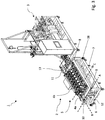
- Fig. 1 to 3 show a filtration system 1.
- the filtration system 1 comprises a filtration unit 2 and a main unit 3.
- the filtration unit 2 comprises at least one filter element 4, a tilting frame 5 and a main frame 6.
- the main frame 6 is provided below the tilting frame 5 and the main frame 6 is configured to support the tilting frame 5.
- the main frame 6 may comprise a frame structure 7 having two support elements 8 and 9 as shown in Fig. 2 and 3 .
- the two support elements 8 and 9 are arranged parallel to each other and extend horizontally, i.e. perpendicular to the force of gravity, so that the support elements 8 and 9 generate a horizontal plane.
- the support elements 8 and 9 extend parallel to a horizontal axis A.
- Each of the support elements 8 and 9 may comprise a bearing 10 and 11 for connecting the tilting frame 5 to the main frame 6.
- the bearings 10 and 11 may be ball bearings.
- An axis extending through the bearings 10 and 11 may represent a tilting axis B.
- the tilting frame 5 may be configured to tilt around the tilting axis B.
- the at least one filter element 4 is arranged in the tilting frame 5 and may tilt around the tilting axis B when the tilting frame 5 is tilted around the tilting axis B.
- the filtration unit 2 comprises at least one actuator 12 connecting the tilting frame 5 and the main frame 6.
- the at least one actuator 12 may be a hydraulic actuator, pneumatic or an electromechanical actuator.
- the at least one filter element 4 may be connected to a conduit arrangement 13 of the tilting frame 5 for supplying the at least one filter element 4 with a fluid.
- the conduit arrangement 13 may be configured to carry the at least one filter element 4.
- the conduit arrangement 13 of the tilting frame 5 may be fluidly connected via conduit element 15 to a conduit arrangement 14 of the main unit 3.
- the conduit element 15 may be provided as a flexible conduit element, so that the main unit 3 and the filtration unit 2 may be positioned flexibly to each other.
- the conduit arrangement 13 may fluidly connect the tilting frame 5 and the main unit 3 in a closed manner thereby maintaining the sterility of the system which is essential for filtration processes of biologicals.
- the conduit element 15 may be a plastic tube or any other suitable connection.
- the at least one filter element 4 may be connected to the conduit arrangement 13 of the tilting frame 5 via an inlet valve 16 and an outlet valve 17.
- the at least one filter element 4 comprises a main flow direction C of the fluid.
- the main flow direction C may correspond to a flow direction of the fluid through the at least one filter element 4 when the fluid flows from the inlet valve 16 towards the outlet valve 17.
- the main flow direction C has a vertical orientation being directed opposite to the force of gravity.
- the orientation of the main flow direction C is changed.
- the orientation of the main flow direction C is changed to a horizontal orientation, the horizontal orientation may be parallel to the horizontal axis A.
- the main unit 3 may further comprise a supply unit 18 for supplying the fluid to the at least one filter element 4.
- the supply unit 18 may comprise a pump 19 fluidly connected to the conduit arrangement 14 of the main unit 3.
- the pump 19 may be configured to pump the fluid to the at least one filter element 4 for supplying and/or evacuating the fluid to/from the at least one filter element 4.
- the main unit 3 may comprise a control unit (not shown) configured to control supplying and/or evacuating the fluid to/from the at least one filter element 4 and to control tilting of the at least one filter element 4 around tilting axis B.
- control unit may be configured to control the inlet valve 16, the outlet valve 17 and the pump 19 in such a manner to supply/evacuate the fluid to/from the at least one filter element 4.
- the at least one filter element 4 may be connected to a venting valve 20 for venting the at least one filter element 4.
- the control unit may also be configured to control the venting valve 20.
- the main unit 3 and the filtration unit 2 are movable.
- wheels 29 are provided on the bottom of the main unit 3 and the filtration unit 2 so that the main unit 3 and the filtration unit 2 can be flexibly positioned with respect to each other.
- the main unit 3 and the filtration unit 2 are configured to be securely positioned on an installation site.
- securing elements 30 may be provided on the bottom of the main unit 3 and the filtration unit 2 for securing the main unit 3 and the filtration unit 2 at the installation site.
- the securing elements 30 may comprise height adjustable stands for securing the main unit 3 and the filtration unit 2 at the installation site.
- the filtration unit 2 may be provided with a motion sensor 28.
- the motion sensor 28 is configured to detect obstacles within the working area of the filtration unit 2. If it is detected that obstacles are within the working area of the filtration unit 2, tilting of the tilting frame 4 is prevented. Thus, it is possible to prevent that an operator is injured when the tilting frame 4 is tilted around the tilting axis.
- the at least one filter element 4 may comprise a first filter element 4a and a second filter element 4b.
- Each of the first filter element 4a and the second filter element 4b is connected to the conduit arrangement 13 of the filtration unit 2 via a respective inlet valve 16, a respective outlet valve 17 and a respective venting valve 20.
- the control unit may be configured to supply/evacuate the fluid to/from the first filter element 4a and the second filter element 4b successively and/or in parallel by appropriately operating the respective inlet valve 16, outlet valve 17 and venting valve 20.
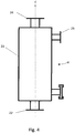
- Fig. 4 shows an exemplary filter element 4.
- the filter element 4 may have a cylindrical wall 21.
- the cylindrical wall 21 extends along the main flow direction C.
- the filter element 4 may have a first port 22 associated to the inlet valve 16, a second port 23 associated to the outlet valve 17 and a third port 24 associated with the venting valve 20.
- the fluid may enter the at least on filter element 4 through the first port 22 and the fluid may be taken out of the at least one filter element 4 through second port 23.
- the main flow direction C may correspond to the flow of the fluid through the filter element 4 when the fluid is flowing from the first port 22 to the second port 23.
- the filter element may be a hollow fibre filter.
- the disclosure is not limited to hollow fibre filters and any other type of filter medium may be used.
- Fig. 5 shows an exemplary filtration process of a fluid according to the present disclosure.
- the filtration process will be described with reference to Fig. 6a to 8b .
- the exemplary filtration process comprises a preparation step S1, a cleaning step S2, a draining step S3, a testing step S4 and a filtration step S5.
- the filtration process may comprise further steps.
- the at least one filter element 4 is inserted into the tilting frame 5 and connected to the conduit arrangement 13 of the filtration unit 2. Furthermore, the main unit 3 is fluidly connected to the filtration unit 2 via the conduit element 15.
- the filtration system 1 may undergo a pressure hold test.
- the pressure hold test is performed to verify that no leaks exist in the filtration system 1, i.e. that the filtration system 1 is leak-proof.
- the at least one filter element 4 is tilted around the tilting axis B in a position so that the main flow direction C is in a vertical orientation.
- the vertical orientation is perpendicular to the horizontal plane and is directed opposite to the force of gravity.
- the filtration system 1 may be cleaned in cleaning step S2.
- the at least one filter element 4 may be tilted around the tilting axis into a position so that the main flow direction C is in the vertical orientation. If the main flow direction C is already in the vertical orientation, the tilting of the at least one filter element 4 is skipped.
- a suitable cleaning fluid is supplied to the at least one filter element 4.
- a cleaning fluid may comprise NaOH or water for injection (WFI).
- the draining step S3 is carried out.
- the at least one filter element 4 is tilted around the tilting axis B so that the orientation of the main flow direction C is changed from a vertical orientation ( Fig. 6a ) into the horizontal orientation ( Fig. 6b ).
- the cleaning fluid remaining in the at least one filter element 4 can be easier evacuated from the at least one filter element 4. Due to the gravity, the cleaning fluid can be easier evacuated through the second port 23.
- an integrity test step of the at least one filter element 4 may be performed.
- the at least one filter element 4 may be tilted around the tilting axis B so that the orientation of the main flow direction C changes from a vertical orientation ( Fig. 7a ) into the horizontal orientation ( Fig. 7b ).
- the at least one filter element 4 is filled with a liquid and pressurised air is provided to the at least one filter element 4 via the first port 22.
- small gas or alr bubbles 25 ascend inside the at least one filter element 4 towards a part of the wall 21 facing up, i.e. away from the installation site.
- a large gas or air bubble 26 formed by the fusion of multiple small gas or air bubbles 25, which individually may be difficult to observe with the large air bubble 26, ascends inside the at least one filter element 4 towards a part of the wall 21 facing up. This allows a better visual inspection of the at least one filter element 4.
- a filtration step S5 may be carried out which is explained with reference to Fig. 8a and Fig. 8b .
- a liquid 27 to be filtered is provided to the at least one filter element 4 via the first port 22 and the at least one filter element 4 is filled with the liquid 27.
- the liquid 27 can be removed from the at least one filter element number 4 via the second port 23 when the fluid 27 reaches a sufficient level inside the at least one filter element 4.
- air bubbles 25 may occur causing a reduced effective filter area of the at least one filter element 4.
- the at least one filter element 4 is tilted around the tilting axis B into a position so that the main flow direction C is between the horizontal orientation and the vertical orientation.
- an tilting angle ⁇ between the main flow direction and the horizontal axis A may be between 0° and 90°, preferably between 30° and 60° and more preferably 45°.
- a tilting angle ⁇ greater than 90° may be advantageous.
Landscapes
- Chemical & Material Sciences (AREA)
- Chemical Kinetics & Catalysis (AREA)
- Filtration Of Liquid (AREA)
Abstract
Description
- The present application relates to a filtration system and a corresponding filtration method for filtering of a fluid.
- In general, in addition to the filtration process itself, the filtration of a fluid requires pre- and post-processing at a filtration system, such as rinsing or cleaning a filter, leakage test or the like. For example, before starting a filtration process, preparation operations may comprise preparing a filtration system, testing the filtration system and cleaning the filtration system. Preparing the filtration system may include operations like mounting filter elements to the filtrations system. During testing, the filtration system may be pressurised to ensure that the filtration system is leak-proof in order to avoid that the fluid may leak from the filtration system. Upon the successful testing of the filtration system, cleaning of the filtration system is performed with suitable cleaning fluids. When it is ensured that the filtration system is leak-proof and cleaned, the actual filtration process may start. After the fluid has been filtered by the filtration system, the filtered liquid is recovered from the filtration system. Afterwards, the filtration system need to be cleaned and drained again.
- Filtration systems which allow for their manipulation by a user before and after use of the filtration systems are known from the prior art:
-
EP 2 208 534 B1 -
WO 2013/187947 A1 discloses a support container for a bioreactor which can be tilted by various angles, including 90 °. In one embodiment a locking pin engages with a corresponding hole in a rotatable collar and allows tilting and fixing the container in the tilted position in various angles. The locking can be done manually. There is disclosed an additional embodiment with a motor and a controller for the motor which allows for automatic tilting of the support container. -
US 9,242,193 B2 -
US 9,616,365 B2 US 9,242,193 B2 US 9,616,365 B2 -
DE 32 40 102 A1 discloses a filter housing accommodating several flat filter elements wherein the filter housing is rotatable around two pins which are each carried by a separate bearing. By means of the two pins which are driven by a drive unit the filter housing can be tilted from a vertical position to a horizontal position in which solid residues can be removed from the filter elements. -
EP 1 671 710 B1 -
US 9,636,609 B2 - In view of the above, it is an object of the invention to provide an improved filtration system which allows an easier handling of the filtration process and involved pre- and post-processing operations.
- The above objects are solved by a filtration system and a filtration method for filtering a fluid as defined in the independent claims. Preferred embodiments are defined in the dependent claims.
- According to an aspect of the invention, a filtration system comprises:
- a filtration unit comprising at least one filter element for filtration of a fluid, the at least one filter element having a main flow direction for the fluid, and wherein the filtration unit is configured to tilt the at least one filter element around a tilting axis to change an orientation of the main flow direction;
- a main unit fluidly connectable to the filtration unit, the main unit comprising:
- a supply unit configured to supply the fluid to the at least one filter element; and
- a control unit configured to control supplying and/or evacuating the fluid to/from the at least one filter element and to control tilting of the at least one filter element around the tilting axis.
- a supply unit configured to supply the fluid to the at least one filter element; and
- The main flow direction of the fluid corresponds to a direction of how the fluid mainly flows through the at least one filter element during a filtration process and/or pre- and post-filtration operations, e.g. testing the filtration system, cleaning the filtration system and draining the filtration system. However, in exceptional cases the fluid may have a flow direction different to the main flow direction. The main flow orientation may be substantially parallel to an imaginary main flow axis of the at least one filter element. Due to the tilting of the at least one filter element, the orientation of the main flow direction and correspondingly the orientation of the main flow axis may change. For example, due to the tilting of the at least one filter element, the orientation of the main flow direction and correspondingly the orientation of the main flow axis may change with respect to a first axis being parallel to a force of gravity and to a horizontal plane being perpendicular to the force of gravity.
- Due to the tilting of the at least one filter element and the gravity acting on the fluid, the at least one filter element may be advantageously positioned for carrying out the filtration process and/or pre-and post-filtration operations.
- The supply unit may comprise a pump unit configured to pump the fluid to the at least one filter element. The pump unit may be connectable to a fluid supply and configured to pump the fluid from the fluid supply to the at least one filter element. The fluid supply may be part of the supply unit. Alternatively, the fluid supply may be separated from the supply unit. The fluid supply may be connected to the pump with a suitable connection member. The connection member may comprise a pipeline, wherein the pipeline may be provided as a flexible or solid pipeline. The control unit may be further configured to control supplying and/or evacuating the fluid to/from the at least one filter element and to control tilting of the at least one filter element dependent on the filtration process and/or the pre-and post-filtration operations.
- Preferably, the filtration unit is fluidly connected to the main unit with a flexible connection. The flexible connection allows a flexible arrangement of the filtration unit with respect to the main unit. For example, it is possible to position the main unit in different angles with respect to the filtration unit in a closed and controlled manner without compromising the sterility of the system.
- Preferably, the filtration unit comprises a tilting frame configured to carry the at least one filter element, the tilting frame being tiltable around the tilting axis. The tilting frame may comprise at least one support member configured to carry the at least one filter element. The at least one support member may be rigidly connected with the tilting frame. Thus, when the tilting frame is tilted around the tilting axis, the at least one support member carrying the at least one filter element is tilted simultaneously. Alternatively, the tilting frame may comprise a conduit system and the at least one filter element is connectable to the conduit system. Hence, when the tilting frame is tilted, the conduit system and the at least one filter element connected to the conduit system are tilted. Thus, when tilting the tilting frame the orientation of the main flow direction is changed.
- Preferably, the filtration unit may comprise a main frame configured to support the tilting frame, the tilting frame being configured to be tiltable with respect to the main frame. For example, a bearing may connect the tilting frame to the main frame and the bearing axis of the bearing may correspond to the tilting axis. The bearing may comprise two ball bearings connecting the main frame with the tilting frame, wherein the tilting axis may correspond to an axis connecting the two ball bearings so that the tilting frame is tiltable around the tilting axis. Furthermore, the main frame may have two opposing support elements. The support elements may extend horizontally and parallel to each other so that the support elements may generate a plane which is parallel to the horizontal plane and/or corresponds to the horizontal plane. When tilting the tilting frame around the tilting axis, the orientation of the main flow direction is changed with respect to the horizontal plane. The ball bearings may be provided at the support members so that the ball bearings are arranged opposite to each other. In other words, each of the ball bearings is associated to a different support element. Thus, the tilting frame may be arranged between the ball bearings and/or the support elements. Hence, the tilting frame is stably connected to the main frame and twisting of the tilting frame during tilting of the tilting frame is reduced.
- Furthermore, the filtration unit may comprise an actuator configured to tilt the tilting frame around the tilting axis. The actuator may be arranged between the tilting frame and the main frame. The actuator may be an electromechanical, pneumatic or hydraulic actuator. Furthermore, it is possible to provide more than one actuator. For example the filtration unit may comprise at least two actuators. The at least two actuators may be arranged opposite to each other, having the same effective direction. For instance, the at least two actuators may be provided at the outer edges of the tilting frame and the main frame. Since the effective directions of the at least two actuators are the same, the tilting frame can be tilted steadily around the tilting axis.
- Preferably, the control unit is configured to tilt the at least one filter element around the tilting axis to change the orientation of the main flow direction between a first orientation and a second orientation. The first orientation may be a horizontal orientation being parallel to the horizontal plane. In other words, the horizontal orientation may be perpendicular to the first axis, the first axis being parallel to the force of gravity. Furthermore, the second orientation may be a vertical orientation which is perpendicular to the horizontal orientation and/or the horizontal plane. In other words, the vertical orientation may be parallel to the first axis being parallel to the force of gravity. Furthermore, the at least one filter element may be tilted so that the orientation of the main flow direction has a certain tilting angle. The tilting angle may be the angle between the horizontal plane and the orientation of the main flow direction. That is, the tilting angle may be 0° when the main flow direction is in the horizontal orientation and parallel to the horizontal plane. Furthermore, the tilting angle may be 90° when the main flow direction is in the vertical orientation and/or when the main flow direction is perpendicular to the horizontal plane. However, the tilting angle may also be greater or smaller than 90°. Consequently, the at least one filter element can be tilted around the tilting axis, thereby changing the orientation of the main flow direction, so that at least one filter element can be arranged in a position being beneficial for the filtration process and/or pre- and post-filtration operations.
- Preferably, the control unit is configured, for a test phase and/or for a recovery phase and/or for a draining phase, to tilt the at least one filter element around the tilting axis to change the orientation of the main flow direction into the first orientation. By arranging the at least one filter element in such a position, gravity can be used to support said phases.
- Preferably, the control unit may be further configured, for a filtration phase, to tilt the at least one filter element around the tilting axis to change the orientation of the main flow direction into an orientation between the first orientation and the second orientation. By arranging the at least one filter element in such a manner, the tilting angle may be between 0° and 90°. In other words, the orientation of the main flow direction may be between the horizontal orientation and the vertical orientation. By positioning the at least one filter element during the filtration phase in such a manner, it is possible to increase the effective filter area of the at least one filter element. Thus, the filtration process can be performed quicker, costs are reduced and less waste is produced.
- Preferably, the control unit may be configured to control an inlet valve and an outlet with, the inlet valve and the outlet valve being associated to the at least one filter element. The control unit may control the inlet valve and the outlet valve in such a manner that the fluid can be supplied and/or evacuated from/to the at least one filter element.
- Preferably, the at least one filter element may comprise a first filter element and a second filter element. The control unit may be configured to supply the fluid to the first filter element and the second filter element successively and/or simultaneously. Furthermore, the control unit may be configured to evacuate the fluid from the first filter element and the second filter element successively and/or in parallel. Thus, the fluid may be supplied and/or evacuated to/from the second filter element after the fluid has been supplied and/or evacuated to/from the first filter element. Alternatively, the steps of supplying and/or evacuating of the fluid to/from the first and the second filter element may be carried out in parallel. Thus, a flexible control is provided for supplying and/or evacuating the fluid to efficiently carry out the filtration process and/or the pre- and post-filtration processes.
- According to a further aspect, a filtration method for filtering of a fluid is provided. The method comprises the steps of:
- providing at least one filter element, the at least one filter element having a main flow direction for the fluid, and wherein the at least one filter element is tiltable around a tilting axis to change an orientation of the main flow direction;
- supplying the fluid to be filtered to the at least one filter element;
- tilting the at least one filter element around the tilting axis to change the orientation of the main flow direction; and
- filtering the fluid to be filtered by the at least one filter element.
- By tilting the at least one filter element around the tilting axis, it is possible to change the orientation of the main flow direction of the fluid. For example, the orientation of the main flow direction may be changed between a horizontal orientation and a vertical orientation. The horizontal orientation may be parallel to a horizontal plane, the horizontal plane being perpendicular to the force of gravity. The vertical orientation may be perpendicular to the horizontal plane and can be directed upwards against the force of gravity. The orientation of the main flow direction can be expressed by a tilting angle, wherein the tilting angle corresponds to an angle between the horizontal plane and the orientation of the main flow direction. When the main flow direction is in the horizontal orientation, the tilting angle is 0° and when the main flow direction is in the vertical orientation, the tilting angle is 90°. However, the tilting angle may be greater or smaller than 90°.
- During filtering the fluid by the at least one filter element, it is beneficial that the tilting angle is between 0° and 90°. By tilting the at least one filter element in a position so that the main flow orientation is different to the vertical orientation, it is possible to increase the effective filter area of the at least one filter element. Thus, filtering can be performed faster, processing costs can be reduced and less waste is generated. However, as an alternative and depending on the design of the filter element a tilting angle greater than 90° may be advantageous.
- Preferably, the method further comprises turning the at least one filter element around the tilting axis to change the orientation of the main flow direction and recovering the fluid from the at least one filter element. For example, the at least one filter element may be tilted until the orientation of the main flow direction is in a horizontal orientation. The horizontal orientation may be parallel to the horizontal plane. By arranging the at least one filter element in a position such that the main flow direction has the horizontal orientation, gravity can be used to improve the recovering of the filtered fluid.
- Preferably, the method further comprises turning the at least one filter element around the tilting axis to change the orientation of the main flow direction and testing the at least one filter element. For example, a pressure test may be carried out to check for any leaks. To perform the pressure test, the vertical orientation of the main flow direction is beneficial. Thus, before performing a pressure test the at least one filter element may be tilted around the tilting axis until the main flow direction is in the vertical orientation. Furthermore, it may be necessary to perform an integrity test of the at least one filter element. For the integrity test of the at least one filter element it is beneficial when the at least one filter element is tilted in a position so that the main flow direction has the horizontal orientation. By tilting the at least one filter element in this position it is possible to identify defects of the at least one filter element.
- The above and other objects, features and advantages of the present invention will become more apparent upon reading of the following detailed description of preferred embodiments and accompanying figures. Other features and advantages of the subject matter described herein will be apparent from the description, the figures and from the claims. It should be understood that even though embodiments are separately described, single features may be combined to additional embodiments.
-
- Fig. 1
- shows exemplary filtration system.
- Fig. 2
- shows a perspective view of an exemplary filtration system.
- Fig. 3
- shows a perspective view of an exemplary filtration system.
- Fig. 4
- shows an exemplary filter element.
- Fig. 5
- shows a flowchart of an exemplary filtration process.
- Fig. 6a and 6b
- show a first example for using the filtration system.
- Fig. 7a and 7b
- show a second example for using the filtration system.
- Fig. 8a and 8b
- show a third example for using the filtration system.
- The figures are schematic representations, which are not up to scale and which may comprise parts that are enlarged or downsized for a better understanding. Further, some parts may be omitted for better understanding.
- In the following, a filtration system according to the present disclosure is described with reference to
Fig. 1 to 3. Fig. 1 to 3 show afiltration system 1. Thefiltration system 1 comprises afiltration unit 2 and amain unit 3. Thefiltration unit 2 comprises at least onefilter element 4, atilting frame 5 and amain frame 6. As shown inFig. 1 , themain frame 6 is provided below the tiltingframe 5 and themain frame 6 is configured to support thetilting frame 5. Themain frame 6 may comprise aframe structure 7 having twosupport elements Fig. 2 and3 . The twosupport elements support elements support elements support elements bearing tilting frame 5 to themain frame 6. Thebearings bearings tilting frame 5 may be configured to tilt around the tilting axis B. The at least onefilter element 4 is arranged in thetilting frame 5 and may tilt around the tilting axis B when thetilting frame 5 is tilted around the tilting axis B. To tilt thetilting frame 5, thefiltration unit 2 comprises at least oneactuator 12 connecting thetilting frame 5 and themain frame 6. For example, the at least oneactuator 12 may be a hydraulic actuator, pneumatic or an electromechanical actuator. - The at least one
filter element 4 may be connected to aconduit arrangement 13 of thetilting frame 5 for supplying the at least onefilter element 4 with a fluid. Theconduit arrangement 13 may be configured to carry the at least onefilter element 4. Theconduit arrangement 13 of thetilting frame 5 may be fluidly connected viaconduit element 15 to aconduit arrangement 14 of themain unit 3. Theconduit element 15 may be provided as a flexible conduit element, so that themain unit 3 and thefiltration unit 2 may be positioned flexibly to each other. Preferably, theconduit arrangement 13 may fluidly connect thetilting frame 5 and themain unit 3 in a closed manner thereby maintaining the sterility of the system which is essential for filtration processes of biologicals. For example, theconduit element 15 may be a plastic tube or any other suitable connection. The at least onefilter element 4 may be connected to theconduit arrangement 13 of thetilting frame 5 via aninlet valve 16 and anoutlet valve 17. - Furthermore, the at least one
filter element 4 comprises a main flow direction C of the fluid. The main flow direction C may correspond to a flow direction of the fluid through the at least onefilter element 4 when the fluid flows from theinlet valve 16 towards theoutlet valve 17. As shown inFig. 1 , the main flow direction C has a vertical orientation being directed opposite to the force of gravity. When tilting thetilting frame 5 around the tilting axis B, the orientation of the main flow direction C is changed. For example, as shown inFig. 3 the orientation of the main flow direction C is changed to a horizontal orientation, the horizontal orientation may be parallel to the horizontal axis A. - The
main unit 3 may further comprise asupply unit 18 for supplying the fluid to the at least onefilter element 4. For example, thesupply unit 18 may comprise apump 19 fluidly connected to theconduit arrangement 14 of themain unit 3. Thepump 19 may be configured to pump the fluid to the at least onefilter element 4 for supplying and/or evacuating the fluid to/from the at least onefilter element 4. Furthermore, themain unit 3 may comprise a control unit (not shown) configured to control supplying and/or evacuating the fluid to/from the at least onefilter element 4 and to control tilting of the at least onefilter element 4 around tilting axis B. In particular, the control unit may be configured to control theinlet valve 16, theoutlet valve 17 and thepump 19 in such a manner to supply/evacuate the fluid to/from the at least onefilter element 4. Furthermore, the at least onefilter element 4 may be connected to a ventingvalve 20 for venting the at least onefilter element 4. The control unit may also be configured to control the ventingvalve 20. - The
main unit 3 and thefiltration unit 2 are movable. For example,wheels 29 are provided on the bottom of themain unit 3 and thefiltration unit 2 so that themain unit 3 and thefiltration unit 2 can be flexibly positioned with respect to each other. Furthermore, themain unit 3 and thefiltration unit 2 are configured to be securely positioned on an installation site. For example, securingelements 30 may be provided on the bottom of themain unit 3 and thefiltration unit 2 for securing themain unit 3 and thefiltration unit 2 at the installation site. For example, the securingelements 30 may comprise height adjustable stands for securing themain unit 3 and thefiltration unit 2 at the installation site. - Additionally, the
filtration unit 2 may be provided with amotion sensor 28. Themotion sensor 28 is configured to detect obstacles within the working area of thefiltration unit 2. If it is detected that obstacles are within the working area of thefiltration unit 2, tilting of thetilting frame 4 is prevented. Thus, it is possible to prevent that an operator is injured when thetilting frame 4 is tilted around the tilting axis. - Furthermore, the at least one
filter element 4 may comprise afirst filter element 4a and asecond filter element 4b. Each of thefirst filter element 4a and thesecond filter element 4b is connected to theconduit arrangement 13 of thefiltration unit 2 via arespective inlet valve 16, arespective outlet valve 17 and arespective venting valve 20. Furthermore, the control unit may be configured to supply/evacuate the fluid to/from thefirst filter element 4a and thesecond filter element 4b successively and/or in parallel by appropriately operating therespective inlet valve 16,outlet valve 17 and ventingvalve 20. -
Fig. 4 shows anexemplary filter element 4. Thefilter element 4 may have acylindrical wall 21. Thecylindrical wall 21 extends along the main flow direction C. Furthermore, thefilter element 4 may have afirst port 22 associated to theinlet valve 16, asecond port 23 associated to theoutlet valve 17 and athird port 24 associated with the ventingvalve 20. The fluid may enter the at least onfilter element 4 through thefirst port 22 and the fluid may be taken out of the at least onefilter element 4 throughsecond port 23. The main flow direction C may correspond to the flow of the fluid through thefilter element 4 when the fluid is flowing from thefirst port 22 to thesecond port 23. For example, the filter element may be a hollow fibre filter. However, the disclosure is not limited to hollow fibre filters and any other type of filter medium may be used. -
Fig. 5 shows an exemplary filtration process of a fluid according to the present disclosure. The filtration process will be described with reference toFig. 6a to 8b . The exemplary filtration process comprises a preparation step S1, a cleaning step S2, a draining step S3, a testing step S4 and a filtration step S5. However, the filtration process may comprise further steps. - During the preparation step S1, the at least one
filter element 4 is inserted into thetilting frame 5 and connected to theconduit arrangement 13 of thefiltration unit 2. Furthermore, themain unit 3 is fluidly connected to thefiltration unit 2 via theconduit element 15. After the preparation step S1 is finished, thefiltration system 1 may undergo a pressure hold test. The pressure hold test is performed to verify that no leaks exist in thefiltration system 1, i.e. that thefiltration system 1 is leak-proof. During the pressure hold test, the at least onefilter element 4 is tilted around the tilting axis B in a position so that the main flow direction C is in a vertical orientation. The vertical orientation is perpendicular to the horizontal plane and is directed opposite to the force of gravity. - When it is verified that the
filtration system 1 is leak-proof, thefiltration system 1 may be cleaned in cleaning step S2. During the cleaning step S2, the at least onefilter element 4 may be tilted around the tilting axis into a position so that the main flow direction C is in the vertical orientation. If the main flow direction C is already in the vertical orientation, the tilting of the at least onefilter element 4 is skipped. During the cleaning step S2, a suitable cleaning fluid is supplied to the at least onefilter element 4. For example, a cleaning fluid may comprise NaOH or water for injection (WFI). - After the cleaning step S2 has been completed, the draining step S3 is carried out. The at least one
filter element 4 is tilted around the tilting axis B so that the orientation of the main flow direction C is changed from a vertical orientation (Fig. 6a ) into the horizontal orientation (Fig. 6b ). By tilting the at least onefilter element 4 around the tilting axis B so that the main flow direction C has the horizontal orientation, the cleaning fluid remaining in the at least onefilter element 4 can be easier evacuated from the at least onefilter element 4. Due to the gravity, the cleaning fluid can be easier evacuated through thesecond port 23. - During testing step S4, an integrity test step of the at least one
filter element 4 may be performed. For the integrity test step, the at least onefilter element 4 may be tilted around the tilting axis B so that the orientation of the main flow direction C changes from a vertical orientation (Fig. 7a ) into the horizontal orientation (Fig. 7b ). Furthermore, the at least onefilter element 4 is filled with a liquid and pressurised air is provided to the at least onefilter element 4 via thefirst port 22. As shown inFig. 7b , due to the horizontal orientation of the main flow direction C, small gas or alr bubbles 25 ascend inside the at least onefilter element 4 towards a part of thewall 21 facing up, i.e. away from the installation site. Furthermore, a large gas orair bubble 26 formed by the fusion of multiple small gas or air bubbles 25, which individually may be difficult to observe with thelarge air bubble 26, ascends inside the at least onefilter element 4 towards a part of thewall 21 facing up. This allows a better visual inspection of the at least onefilter element 4. - When the
filtration system 1 has been drained and tested, a filtration step S5 may be carried out which is explained with reference toFig. 8a and Fig. 8b . During the filtration step S5, a liquid 27 to be filtered is provided to the at least onefilter element 4 via thefirst port 22 and the at least onefilter element 4 is filled with the liquid 27. Furthermore, the liquid 27 can be removed from the at least onefilter element number 4 via thesecond port 23 when the fluid 27 reaches a sufficient level inside the at least onefilter element 4. However, in the upper area of the at least onefilter element 4 air bubbles 25 may occur causing a reduced effective filter area of the at least onefilter element 4. Thus, during the filtration step S5, the at least onefilter element 4 is tilted around the tilting axis B into a position so that the main flow direction C is between the horizontal orientation and the vertical orientation. For example, an tilting angle α between the main flow direction and the horizontal axis A may be between 0° and 90°, preferably between 30° and 60° and more preferably 45°. However, depending upon the type and design of the at least onefilter element 4, a tilting angle α greater than 90° may be advantageous. When tilting the at least onefilter element 4 in such a manner and thereby changing the orientation of the main flow direction, the area for air bubbles 25 inside the at least onefilter element number 4 is reduced. Consequently, the effective filter area of the at least onefilter element 4 is increased. This leads to a faster filtration processing, reduced cost and less waste. -
- 1
- filtration system
- 2
- filtration unit
- 3
- main unit
- 4
- at least one filter element
- 4a
- first filter element
- 4b
- second filter element
- 5
- tilting frame
- 6
- main frame
- 7
- frame structure
- 8, 9
- support elements
- 10, 11
- bearings
- 12
- actuator
- 13
- conduit arrangement (of the filtration unit)
- 14
- conduit arrangement (of the main unit)
- 15
- conduit element
- 16
- inlet valve
- 17
- outlet valve
- 18
- supply unit
- 19
- pump
- 20
- venting valve
- 21
- wall
- 22
- first port
- 23
- second port
- 24
- third port
- 25
- air bubbles
- 26
- large air bubble
- 27
- liquid
- 28
- motion sensor
- 29
- wheels
- 30
- securing elements
- A
- horizontal axis
- B
- tilting axis
- C
- main flow direction
Claims (12)
- A filtration system (1) comprising:- a filtration unit (2) comprising at least one filter element (4) for filtration of a fluid, the at least one filter element (4) having a main flow direction (C) for the fluid, and wherein the filtration unit (2) is configured to tilt the at least one filter element (4) around a tilting axis (B) to change an orientation of the main flow direction (C);- a main unit (3) fluidly connectable to the filtration unit (2), the main unit comprising:- a supply unit (18) configured to supply the fluid to the at least one filter element (4); and- a control unit configured to control supplying and/or evacuating the fluid to/from the at least one filter element (4) and to control tilting of the at least one filter element (4) around the tilting axis (B).
- The filtration system (1) according to claim 1, wherein the filtration unit (2) is fluidly connected to the main unit (3) with a flexible connection (15) in a closed manner.
- The filtration system (1) according to claim 1 or 2, wherein the filtration unit comprises a tilting frame (5) configured to carry the at least one filter element (4), the tilting frame (5) being tiltable around the tilting axis (B).
- The filtration system (1) according to claim 3, wherein the filtration unit (2) comprises a main frame (6) configured to support the tilting frame (5), the tilting frame (5) being configured to be tiltable with respect to the main frame (6).
- The filtration system (1) according to any one of the preceding claims, wherein the control unit is configured to tilt the at least one filter element (4) around the tilting axis to change the orientation of the main flow direction (C) between a first orientation and a second orientation, and wherein the first orientation may be a horizontal orientation and the second orientation may be a vertical orientation.
- The filtration system (1) according to claim 5, wherein the control unit is configured, for a test phase and/or for a recovery phase and/or for a draining phase, to tilt the at least one filter element (4) around the tilting axis (B) to change the orientation of the main flow direction (C) into the first orientation.
- The filtration system (1) according to claim 5 or 6, wherein the control unit is configured, for a filtration phase, to tilt the at least one filter element (4) around the tilting axis (B) to change the orientation of the main flow direction (C) into an orientation between the first orientation and the second orientation.
- The filtration system (1) according to any one of the preceding claims, wherein the control unit is configured to control an inlet valve (16) and an outlet valve (17), the inlet valve (16) and the outlet valve (17) being associated to the at least one filter element (4).
- The filtration system (1) according to any one of the preceding claims, wherein the at least one filter element (4) comprises a first filter element (4a) and a second filter element (4b), and
wherein the control unit is configured to supplying the fluid to the first filter element (4a) and the second filter element (4b) successively and/or simultaneously, and/or
wherein the control unit is configured to evacuating the fluid from the first filter element (4a) and the second filter element (4b) successively and/or simultaneously. - A filtration method for filtering of a fluid, the method comprising:providing at least one filter element (4), the at least one filter element (4) having a main flow direction (C) for the fluid, and wherein the at least one filter element (4) is tiltable around a tilting axis (B) to change an orientation of the main flow direction (C);supplying the fluid to be filtered to the at least one filter element (4);tilting the at least one filter element (4) around the tilting axis (B) to change the orientation of the main flow direction (C); andfiltering the fluid to be filtered by the at least one filter element (4).
- The filtration method according to claim 10, further comprising:turning the at least one filter element (4) around the tilting axis (B) to change the orientation of the main flow direction (C); andrecovering the filtered fluid from the at least one filter element (4).
- The filtration method according to claims 10 and 11, further comprising:turning the at least one filter element (4) around the tilting axis (B) to change the orientation of the main flow direction; andtesting the at least one filter element (4).
Priority Applications (4)
| Application Number | Priority Date | Filing Date | Title |
|---|---|---|---|
| EP17001566.3A EP3456399B1 (en) | 2017-09-19 | 2017-09-19 | Filter skid with tilting mechanism |
| KR1020180101262A KR102240681B1 (en) | 2017-09-19 | 2018-08-28 | Filter skid with tilting mechanism |
| CN201811086272.2A CN109513250B (en) | 2017-09-19 | 2018-09-18 | Filtration system and filtration method for filtering a fluid |
| US16/135,066 US11285410B2 (en) | 2017-09-19 | 2018-09-19 | Filter skid with tilting mechanism |
Applications Claiming Priority (1)
| Application Number | Priority Date | Filing Date | Title |
|---|---|---|---|
| EP17001566.3A EP3456399B1 (en) | 2017-09-19 | 2017-09-19 | Filter skid with tilting mechanism |
Publications (2)
| Publication Number | Publication Date |
|---|---|
| EP3456399A1 true EP3456399A1 (en) | 2019-03-20 |
| EP3456399B1 EP3456399B1 (en) | 2020-08-19 |
Family
ID=60117428
Family Applications (1)
| Application Number | Title | Priority Date | Filing Date |
|---|---|---|---|
| EP17001566.3A Active EP3456399B1 (en) | 2017-09-19 | 2017-09-19 | Filter skid with tilting mechanism |
Country Status (4)
| Country | Link |
|---|---|
| US (1) | US11285410B2 (en) |
| EP (1) | EP3456399B1 (en) |
| KR (1) | KR102240681B1 (en) |
| CN (1) | CN109513250B (en) |
Families Citing this family (8)
| Publication number | Priority date | Publication date | Assignee | Title |
|---|---|---|---|---|
| EP3456399B1 (en) * | 2017-09-19 | 2020-08-19 | Sartorius Stedim Biotech GmbH | Filter skid with tilting mechanism |
| US11679348B2 (en) * | 2017-12-29 | 2023-06-20 | Enercorp Engineered Solutions Inc. | Horizontal sand separator assembly |
| US11911719B2 (en) * | 2019-09-20 | 2024-02-27 | Massachusetts Institute Of Technology | Devices and methods for the integrated filtration, drying, and mechanical processing of active pharmaceutical ingredients |
| KR20210132921A (en) * | 2020-04-28 | 2021-11-05 | 주식회사 아모그린텍 | filter module for water-purifying device using gravity and water-purifying device including the same |
| USD1033591S1 (en) | 2021-07-14 | 2024-07-02 | Emd Millipore Corporation | Filter assembly stand |
| USD1025288S1 (en) | 2021-07-14 | 2024-04-30 | Emd Millipore Corporation | Filter assembly bracket |
| USD1024269S1 (en) | 2021-07-14 | 2024-04-23 | Emd Millipore Corporation | Filter assembly holder |
| DK4476317T3 (en) * | 2022-02-10 | 2026-02-09 | Just Evotec Biologics Inc | DEPTH FILTER AND VIRUS FILTER CART (DF/VF) FOR BATCH AND CONTINUOUS PRODUCTION |
Citations (10)
| Publication number | Priority date | Publication date | Assignee | Title |
|---|---|---|---|---|
| GB619973A (en) * | 1946-07-09 | 1949-03-17 | Paterson Engineering Company L | Improvements in apparatus for filtration of liquids |
| DE3240102A1 (en) | 1982-10-29 | 1984-05-03 | Karl W. 5064 Rösrath Loeffler | Filter apparatus |
| US20080105605A1 (en) * | 2006-05-19 | 2008-05-08 | Eco Creative Japan, Co., Ltd | Water treating apparatus |
| EP1671710B1 (en) | 2004-12-15 | 2008-07-09 | ESTA Apparatebau GmbH & Co.KG | Suction and filtering device |
| WO2013187947A1 (en) | 2012-06-15 | 2013-12-19 | Hyclone Laboratories, Inc. | Fluid mixing system with tiltable support housing |
| EP2208534B1 (en) | 2008-12-24 | 2014-03-05 | EMD Millipore Corporation | Cart and installation for treating a biological liquid |
| JP2015112516A (en) * | 2013-12-10 | 2015-06-22 | 三菱レイヨン株式会社 | Water treatment apparatus and exchange method of membrane element |
| US9242193B2 (en) | 2009-10-30 | 2016-01-26 | 3M Innovative Properties Company | Filter apparatus and method of use |
| US9616365B2 (en) | 2011-09-19 | 2017-04-11 | 3M Innovative Properties Company | Indexing filter apparatus and method of use |
| US9636609B2 (en) | 2008-07-25 | 2017-05-02 | Smith & Nephew Plc | Controller for an acoustic standing wave generation device in order to prevent clogging of a filter |
Family Cites Families (24)
| Publication number | Priority date | Publication date | Assignee | Title |
|---|---|---|---|---|
| US719438A (en) * | 1902-04-25 | 1903-02-03 | John G Crossman | Filter and extractor press. |
| US1120629A (en) * | 1914-11-02 | 1914-12-08 | Orange J Salisbury | Filtering apparatus. |
| US1898604A (en) * | 1927-11-03 | 1933-02-21 | Dunlop Rubber Co | Method and apparatus for concentrating liquids |
| US2552360A (en) * | 1945-01-10 | 1951-05-08 | Zichis Joseph | Method of and apparatus for dehydrating materials |
| US2496370A (en) * | 1946-07-09 | 1950-02-07 | Paterson Engineering Company L | Apparatus for filtration of liquids |
| US2605903A (en) * | 1948-06-22 | 1952-08-05 | Arthur A Schuller | Filter |
| US3403640A (en) * | 1964-06-22 | 1968-10-01 | Schroder Herbert | Dough dividing or batching machine |
| DE1551021A1 (en) * | 1965-11-08 | 1970-01-02 | Fives Penhoet Soc | Forced circulation heat exchanger |
| US3494467A (en) * | 1968-04-03 | 1970-02-10 | Douglas A Paisley | Horizontal leaf dry cake discharge filter |
| US3980560A (en) * | 1975-01-27 | 1976-09-14 | Delaval Turbine Inc. | Filter construction |
| LU73553A1 (en) * | 1975-10-09 | 1977-05-24 | ||
| US4340477A (en) * | 1979-04-30 | 1982-07-20 | Hobson Jr Russell B | Vacuum sludge receiver |
| US4417980A (en) * | 1980-06-18 | 1983-11-29 | Schenk Filterbau Gmbh | Filtration apparatus |
| JPS5835726B2 (en) * | 1980-09-19 | 1983-08-04 | 日本染色機械株式会社 | filtration device |
| US4705222A (en) * | 1985-05-03 | 1987-11-10 | Processall, Inc. | Multipurpose mixer |
| DE3641952A1 (en) * | 1986-12-09 | 1988-06-23 | Schenk Filterbau Gmbh | PROCESS FILTER |
| US5397462A (en) * | 1993-08-24 | 1995-03-14 | Matsushita Electric Industrial Co., Ltd. | Filter with laterally removable element and valve means |
| US6290383B1 (en) * | 1998-06-24 | 2001-09-18 | Processall, Inc. | Apparatus mixing, filtering, reacting and drying materials |
| US6601315B2 (en) * | 2000-12-14 | 2003-08-05 | Bausch & Lomb Incorporated | Combined fluidized bed dryer and absorption bed |
| US20040050802A1 (en) * | 2002-05-17 | 2004-03-18 | Banister John Patrick | Fluid bed filter-dryer apparatus |
| US7473375B2 (en) * | 2004-05-23 | 2009-01-06 | Rosenmund Vta Ag | Method and device for removal of residual products |
| DE102008029533A1 (en) * | 2008-06-21 | 2009-12-24 | Krones Ag | Device for handling, in particular filtration of liquids |
| US20130319925A1 (en) | 2012-06-01 | 2013-12-05 | Eaton Corporation | Fluid filtration system |
| EP3456399B1 (en) * | 2017-09-19 | 2020-08-19 | Sartorius Stedim Biotech GmbH | Filter skid with tilting mechanism |
-
2017
- 2017-09-19 EP EP17001566.3A patent/EP3456399B1/en active Active
-
2018
- 2018-08-28 KR KR1020180101262A patent/KR102240681B1/en active Active
- 2018-09-18 CN CN201811086272.2A patent/CN109513250B/en active Active
- 2018-09-19 US US16/135,066 patent/US11285410B2/en active Active
Patent Citations (10)
| Publication number | Priority date | Publication date | Assignee | Title |
|---|---|---|---|---|
| GB619973A (en) * | 1946-07-09 | 1949-03-17 | Paterson Engineering Company L | Improvements in apparatus for filtration of liquids |
| DE3240102A1 (en) | 1982-10-29 | 1984-05-03 | Karl W. 5064 Rösrath Loeffler | Filter apparatus |
| EP1671710B1 (en) | 2004-12-15 | 2008-07-09 | ESTA Apparatebau GmbH & Co.KG | Suction and filtering device |
| US20080105605A1 (en) * | 2006-05-19 | 2008-05-08 | Eco Creative Japan, Co., Ltd | Water treating apparatus |
| US9636609B2 (en) | 2008-07-25 | 2017-05-02 | Smith & Nephew Plc | Controller for an acoustic standing wave generation device in order to prevent clogging of a filter |
| EP2208534B1 (en) | 2008-12-24 | 2014-03-05 | EMD Millipore Corporation | Cart and installation for treating a biological liquid |
| US9242193B2 (en) | 2009-10-30 | 2016-01-26 | 3M Innovative Properties Company | Filter apparatus and method of use |
| US9616365B2 (en) | 2011-09-19 | 2017-04-11 | 3M Innovative Properties Company | Indexing filter apparatus and method of use |
| WO2013187947A1 (en) | 2012-06-15 | 2013-12-19 | Hyclone Laboratories, Inc. | Fluid mixing system with tiltable support housing |
| JP2015112516A (en) * | 2013-12-10 | 2015-06-22 | 三菱レイヨン株式会社 | Water treatment apparatus and exchange method of membrane element |
Also Published As
| Publication number | Publication date |
|---|---|
| CN109513250B (en) | 2021-04-06 |
| CN109513250A (en) | 2019-03-26 |
| KR102240681B1 (en) | 2021-04-16 |
| EP3456399B1 (en) | 2020-08-19 |
| KR20190032181A (en) | 2019-03-27 |
| US11285410B2 (en) | 2022-03-29 |
| US20190083910A1 (en) | 2019-03-21 |
Similar Documents
| Publication | Publication Date | Title |
|---|---|---|
| US11285410B2 (en) | Filter skid with tilting mechanism | |
| US5512168A (en) | Programmable solid phase extraction and elution device | |
| ES2589782T3 (en) | Manifold set | |
| KR102489816B1 (en) | Method and machine for producing sterile solution product bags | |
| JP5017318B2 (en) | Instrument for automatic analysis of samples on gel cards | |
| JPH04164257A (en) | Automatic pretreatment device | |
| KR20130050951A (en) | Device for a biological liquid treatment installation | |
| EP2730326B1 (en) | Systems and methods for conditioning a filter assembly | |
| JP7478546B2 (en) | Cultivation system, culture device, and multi-layer culture vessel operation device | |
| US11376527B2 (en) | Production system for forming filtration tubes including subsystems and method of using same | |
| AU2021412877A1 (en) | Method and system for producing sterile solution filled containers | |
| CN116348189A (en) | Modular devices for the fixed arrangement and interconnection of individual separate and/or functional units with one another | |
| US6334340B1 (en) | Liquified gas dry-cleaning machine with convertible installation configuration | |
| US12172200B2 (en) | Automated cleaning methods for internal cavities of pressure instruments | |
| JP2010158174A (en) | Cell culture apparatus having flow channel-washing mechanism and method for controlling the same | |
| CN118541219A (en) | Separation component, purification device and control method | |
| CN115135398A (en) | Disposable device for separating or purifying a large number of substance mixtures | |
| CN103796728A (en) | Indexing filter apparatus and method of use | |
| JP2011092212A (en) | Method for controlling cell culture apparatus | |
| CN115810532A (en) | Substrate processing method and substrate processing device | |
| CN113041701B (en) | Method and system for recovering fluids | |
| US7658198B2 (en) | Washing system for dissolution vessels and the like | |
| JPH01231979A (en) | Method and device for cleaning viscometer for high-viscosity oil | |
| US7753060B2 (en) | Cellular aqueous tube cleaning system and method | |
| JP2005512780A (en) | Filtration device |
Legal Events
| Date | Code | Title | Description |
|---|---|---|---|
| PUAI | Public reference made under article 153(3) epc to a published international application that has entered the european phase |
Free format text: ORIGINAL CODE: 0009012 |
|
| STAA | Information on the status of an ep patent application or granted ep patent |
Free format text: STATUS: THE APPLICATION HAS BEEN PUBLISHED |
|
| AK | Designated contracting states |
Kind code of ref document: A1 Designated state(s): AL AT BE BG CH CY CZ DE DK EE ES FI FR GB GR HR HU IE IS IT LI LT LU LV MC MK MT NL NO PL PT RO RS SE SI SK SM TR |
|
| AX | Request for extension of the european patent |
Extension state: BA ME |
|
| STAA | Information on the status of an ep patent application or granted ep patent |
Free format text: STATUS: REQUEST FOR EXAMINATION WAS MADE |
|
| 17P | Request for examination filed |
Effective date: 20190905 |
|
| RBV | Designated contracting states (corrected) |
Designated state(s): AL AT BE BG CH CY CZ DE DK EE ES FI FR GB GR HR HU IE IS IT LI LT LU LV MC MK MT NL NO PL PT RO RS SE SI SK SM TR |
|
| GRAP | Despatch of communication of intention to grant a patent |
Free format text: ORIGINAL CODE: EPIDOSNIGR1 |
|
| STAA | Information on the status of an ep patent application or granted ep patent |
Free format text: STATUS: GRANT OF PATENT IS INTENDED |
|
| INTG | Intention to grant announced |
Effective date: 20200528 |
|
| GRAS | Grant fee paid |
Free format text: ORIGINAL CODE: EPIDOSNIGR3 |
|
| GRAA | (expected) grant |
Free format text: ORIGINAL CODE: 0009210 |
|
| STAA | Information on the status of an ep patent application or granted ep patent |
Free format text: STATUS: THE PATENT HAS BEEN GRANTED |
|
| AK | Designated contracting states |
Kind code of ref document: B1 Designated state(s): AL AT BE BG CH CY CZ DE DK EE ES FI FR GB GR HR HU IE IS IT LI LT LU LV MC MK MT NL NO PL PT RO RS SE SI SK SM TR |
|
| REG | Reference to a national code |
Ref country code: CH Ref legal event code: EP Ref country code: CH Ref legal event code: NV Representative=s name: NOVAGRAAF INTERNATIONAL SA, CH |
|
| REG | Reference to a national code |
Ref country code: DE Ref legal event code: R096 Ref document number: 602017021744 Country of ref document: DE |
|
| REG | Reference to a national code |
Ref country code: AT Ref legal event code: REF Ref document number: 1303300 Country of ref document: AT Kind code of ref document: T Effective date: 20200915 |
|
| REG | Reference to a national code |
Ref country code: IE Ref legal event code: FG4D |
|
| REG | Reference to a national code |
Ref country code: SE Ref legal event code: TRGR |
|
| REG | Reference to a national code |
Ref country code: LT Ref legal event code: MG4D |
|
| REG | Reference to a national code |
Ref country code: NL Ref legal event code: MP Effective date: 20200819 |
|
| PG25 | Lapsed in a contracting state [announced via postgrant information from national office to epo] |
Ref country code: FI Free format text: LAPSE BECAUSE OF FAILURE TO SUBMIT A TRANSLATION OF THE DESCRIPTION OR TO PAY THE FEE WITHIN THE PRESCRIBED TIME-LIMIT Effective date: 20200819 Ref country code: GR Free format text: LAPSE BECAUSE OF FAILURE TO SUBMIT A TRANSLATION OF THE DESCRIPTION OR TO PAY THE FEE WITHIN THE PRESCRIBED TIME-LIMIT Effective date: 20201120 Ref country code: LT Free format text: LAPSE BECAUSE OF FAILURE TO SUBMIT A TRANSLATION OF THE DESCRIPTION OR TO PAY THE FEE WITHIN THE PRESCRIBED TIME-LIMIT Effective date: 20200819 Ref country code: PT Free format text: LAPSE BECAUSE OF FAILURE TO SUBMIT A TRANSLATION OF THE DESCRIPTION OR TO PAY THE FEE WITHIN THE PRESCRIBED TIME-LIMIT Effective date: 20201221 Ref country code: HR Free format text: LAPSE BECAUSE OF FAILURE TO SUBMIT A TRANSLATION OF THE DESCRIPTION OR TO PAY THE FEE WITHIN THE PRESCRIBED TIME-LIMIT Effective date: 20200819 Ref country code: NO Free format text: LAPSE BECAUSE OF FAILURE TO SUBMIT A TRANSLATION OF THE DESCRIPTION OR TO PAY THE FEE WITHIN THE PRESCRIBED TIME-LIMIT Effective date: 20201119 Ref country code: BG Free format text: LAPSE BECAUSE OF FAILURE TO SUBMIT A TRANSLATION OF THE DESCRIPTION OR TO PAY THE FEE WITHIN THE PRESCRIBED TIME-LIMIT Effective date: 20201119 |
|
| REG | Reference to a national code |
Ref country code: AT Ref legal event code: MK05 Ref document number: 1303300 Country of ref document: AT Kind code of ref document: T Effective date: 20200819 |
|
| PG25 | Lapsed in a contracting state [announced via postgrant information from national office to epo] |
Ref country code: PL Free format text: LAPSE BECAUSE OF FAILURE TO SUBMIT A TRANSLATION OF THE DESCRIPTION OR TO PAY THE FEE WITHIN THE PRESCRIBED TIME-LIMIT Effective date: 20200819 Ref country code: NL Free format text: LAPSE BECAUSE OF FAILURE TO SUBMIT A TRANSLATION OF THE DESCRIPTION OR TO PAY THE FEE WITHIN THE PRESCRIBED TIME-LIMIT Effective date: 20200819 Ref country code: LV Free format text: LAPSE BECAUSE OF FAILURE TO SUBMIT A TRANSLATION OF THE DESCRIPTION OR TO PAY THE FEE WITHIN THE PRESCRIBED TIME-LIMIT Effective date: 20200819 Ref country code: RS Free format text: LAPSE BECAUSE OF FAILURE TO SUBMIT A TRANSLATION OF THE DESCRIPTION OR TO PAY THE FEE WITHIN THE PRESCRIBED TIME-LIMIT Effective date: 20200819 Ref country code: IS Free format text: LAPSE BECAUSE OF FAILURE TO SUBMIT A TRANSLATION OF THE DESCRIPTION OR TO PAY THE FEE WITHIN THE PRESCRIBED TIME-LIMIT Effective date: 20201219 |
|
| PG25 | Lapsed in a contracting state [announced via postgrant information from national office to epo] |
Ref country code: EE Free format text: LAPSE BECAUSE OF FAILURE TO SUBMIT A TRANSLATION OF THE DESCRIPTION OR TO PAY THE FEE WITHIN THE PRESCRIBED TIME-LIMIT Effective date: 20200819 Ref country code: SM Free format text: LAPSE BECAUSE OF FAILURE TO SUBMIT A TRANSLATION OF THE DESCRIPTION OR TO PAY THE FEE WITHIN THE PRESCRIBED TIME-LIMIT Effective date: 20200819 Ref country code: DK Free format text: LAPSE BECAUSE OF FAILURE TO SUBMIT A TRANSLATION OF THE DESCRIPTION OR TO PAY THE FEE WITHIN THE PRESCRIBED TIME-LIMIT Effective date: 20200819 Ref country code: CZ Free format text: LAPSE BECAUSE OF FAILURE TO SUBMIT A TRANSLATION OF THE DESCRIPTION OR TO PAY THE FEE WITHIN THE PRESCRIBED TIME-LIMIT Effective date: 20200819 Ref country code: RO Free format text: LAPSE BECAUSE OF FAILURE TO SUBMIT A TRANSLATION OF THE DESCRIPTION OR TO PAY THE FEE WITHIN THE PRESCRIBED TIME-LIMIT Effective date: 20200819 |
|
| REG | Reference to a national code |
Ref country code: DE Ref legal event code: R097 Ref document number: 602017021744 Country of ref document: DE |
|
| PG25 | Lapsed in a contracting state [announced via postgrant information from national office to epo] |
Ref country code: MC Free format text: LAPSE BECAUSE OF FAILURE TO SUBMIT A TRANSLATION OF THE DESCRIPTION OR TO PAY THE FEE WITHIN THE PRESCRIBED TIME-LIMIT Effective date: 20200819 Ref country code: ES Free format text: LAPSE BECAUSE OF FAILURE TO SUBMIT A TRANSLATION OF THE DESCRIPTION OR TO PAY THE FEE WITHIN THE PRESCRIBED TIME-LIMIT Effective date: 20200819 Ref country code: AL Free format text: LAPSE BECAUSE OF FAILURE TO SUBMIT A TRANSLATION OF THE DESCRIPTION OR TO PAY THE FEE WITHIN THE PRESCRIBED TIME-LIMIT Effective date: 20200819 Ref country code: AT Free format text: LAPSE BECAUSE OF FAILURE TO SUBMIT A TRANSLATION OF THE DESCRIPTION OR TO PAY THE FEE WITHIN THE PRESCRIBED TIME-LIMIT Effective date: 20200819 |
|
| REG | Reference to a national code |
Ref country code: BE Ref legal event code: MM Effective date: 20200930 |
|
| PLBE | No opposition filed within time limit |
Free format text: ORIGINAL CODE: 0009261 |
|
| STAA | Information on the status of an ep patent application or granted ep patent |
Free format text: STATUS: NO OPPOSITION FILED WITHIN TIME LIMIT |
|
| PG25 | Lapsed in a contracting state [announced via postgrant information from national office to epo] |
Ref country code: LU Free format text: LAPSE BECAUSE OF NON-PAYMENT OF DUE FEES Effective date: 20200919 Ref country code: SK Free format text: LAPSE BECAUSE OF FAILURE TO SUBMIT A TRANSLATION OF THE DESCRIPTION OR TO PAY THE FEE WITHIN THE PRESCRIBED TIME-LIMIT Effective date: 20200819 |
|
| 26N | No opposition filed |
Effective date: 20210520 |
|
| PG25 | Lapsed in a contracting state [announced via postgrant information from national office to epo] |
Ref country code: IT Free format text: LAPSE BECAUSE OF FAILURE TO SUBMIT A TRANSLATION OF THE DESCRIPTION OR TO PAY THE FEE WITHIN THE PRESCRIBED TIME-LIMIT Effective date: 20200819 |
|
| PG25 | Lapsed in a contracting state [announced via postgrant information from national office to epo] |
Ref country code: SI Free format text: LAPSE BECAUSE OF FAILURE TO SUBMIT A TRANSLATION OF THE DESCRIPTION OR TO PAY THE FEE WITHIN THE PRESCRIBED TIME-LIMIT Effective date: 20200819 Ref country code: IE Free format text: LAPSE BECAUSE OF NON-PAYMENT OF DUE FEES Effective date: 20200919 Ref country code: BE Free format text: LAPSE BECAUSE OF NON-PAYMENT OF DUE FEES Effective date: 20200930 |
|
| PG25 | Lapsed in a contracting state [announced via postgrant information from national office to epo] |
Ref country code: TR Free format text: LAPSE BECAUSE OF FAILURE TO SUBMIT A TRANSLATION OF THE DESCRIPTION OR TO PAY THE FEE WITHIN THE PRESCRIBED TIME-LIMIT Effective date: 20200819 Ref country code: MT Free format text: LAPSE BECAUSE OF FAILURE TO SUBMIT A TRANSLATION OF THE DESCRIPTION OR TO PAY THE FEE WITHIN THE PRESCRIBED TIME-LIMIT Effective date: 20200819 Ref country code: CY Free format text: LAPSE BECAUSE OF FAILURE TO SUBMIT A TRANSLATION OF THE DESCRIPTION OR TO PAY THE FEE WITHIN THE PRESCRIBED TIME-LIMIT Effective date: 20200819 |
|
| PG25 | Lapsed in a contracting state [announced via postgrant information from national office to epo] |
Ref country code: MK Free format text: LAPSE BECAUSE OF FAILURE TO SUBMIT A TRANSLATION OF THE DESCRIPTION OR TO PAY THE FEE WITHIN THE PRESCRIBED TIME-LIMIT Effective date: 20200819 |
|
| P01 | Opt-out of the competence of the unified patent court (upc) registered |
Effective date: 20230526 |
|
| REG | Reference to a national code |
Ref country code: CH Ref legal event code: U11 Free format text: ST27 STATUS EVENT CODE: U-0-0-U10-U11 (AS PROVIDED BY THE NATIONAL OFFICE) Effective date: 20251001 |
|
| PGFP | Annual fee paid to national office [announced via postgrant information from national office to epo] |
Ref country code: DE Payment date: 20250919 Year of fee payment: 9 |
|
| PGFP | Annual fee paid to national office [announced via postgrant information from national office to epo] |
Ref country code: GB Payment date: 20250923 Year of fee payment: 9 |
|
| PGFP | Annual fee paid to national office [announced via postgrant information from national office to epo] |
Ref country code: FR Payment date: 20250926 Year of fee payment: 9 |
|
| PGFP | Annual fee paid to national office [announced via postgrant information from national office to epo] |
Ref country code: SE Payment date: 20250922 Year of fee payment: 9 |
|
| PGFP | Annual fee paid to national office [announced via postgrant information from national office to epo] |
Ref country code: CH Payment date: 20251001 Year of fee payment: 9 |