EP3456177A1 - Baler - Google Patents
Baler Download PDFInfo
- Publication number
- EP3456177A1 EP3456177A1 EP18191895.4A EP18191895A EP3456177A1 EP 3456177 A1 EP3456177 A1 EP 3456177A1 EP 18191895 A EP18191895 A EP 18191895A EP 3456177 A1 EP3456177 A1 EP 3456177A1
- Authority
- EP
- European Patent Office
- Prior art keywords
- output shaft
- driven output
- baler
- compression chamber
- rotation
- Prior art date
- Legal status (The legal status is an assumption and is not a legal conclusion. Google has not performed a legal analysis and makes no representation as to the accuracy of the status listed.)
- Granted
Links
Images



Classifications
-
- A—HUMAN NECESSITIES
- A01—AGRICULTURE; FORESTRY; ANIMAL HUSBANDRY; HUNTING; TRAPPING; FISHING
- A01F—PROCESSING OF HARVESTED PRODUCE; HAY OR STRAW PRESSES; DEVICES FOR STORING AGRICULTURAL OR HORTICULTURAL PRODUCE
- A01F15/00—Baling presses for straw, hay or the like
- A01F15/08—Details
- A01F15/10—Feeding devices for the crop material e.g. precompression devices
-
- A—HUMAN NECESSITIES
- A01—AGRICULTURE; FORESTRY; ANIMAL HUSBANDRY; HUNTING; TRAPPING; FISHING
- A01D—HARVESTING; MOWING
- A01D89/00—Pick-ups for loaders, chaff-cutters, balers, field-threshers, or the like, i.e. attachments for picking-up hay or the like field crops
- A01D89/001—Pick-up systems
-
- A—HUMAN NECESSITIES
- A01—AGRICULTURE; FORESTRY; ANIMAL HUSBANDRY; HUNTING; TRAPPING; FISHING
- A01F—PROCESSING OF HARVESTED PRODUCE; HAY OR STRAW PRESSES; DEVICES FOR STORING AGRICULTURAL OR HORTICULTURAL PRODUCE
- A01F15/00—Baling presses for straw, hay or the like
- A01F15/04—Plunger presses
-
- A—HUMAN NECESSITIES
- A01—AGRICULTURE; FORESTRY; ANIMAL HUSBANDRY; HUNTING; TRAPPING; FISHING
- A01F—PROCESSING OF HARVESTED PRODUCE; HAY OR STRAW PRESSES; DEVICES FOR STORING AGRICULTURAL OR HORTICULTURAL PRODUCE
- A01F15/00—Baling presses for straw, hay or the like
- A01F15/08—Details
- A01F15/10—Feeding devices for the crop material e.g. precompression devices
- A01F15/101—Feeding at right angles to the compression stroke
-
- A—HUMAN NECESSITIES
- A01—AGRICULTURE; FORESTRY; ANIMAL HUSBANDRY; HUNTING; TRAPPING; FISHING
- A01F—PROCESSING OF HARVESTED PRODUCE; HAY OR STRAW PRESSES; DEVICES FOR STORING AGRICULTURAL OR HORTICULTURAL PRODUCE
- A01F15/00—Baling presses for straw, hay or the like
- A01F15/08—Details
- A01F15/10—Feeding devices for the crop material e.g. precompression devices
- A01F15/101—Feeding at right angles to the compression stroke
- A01F2015/102—Feeding at right angles to the compression stroke the pressing chamber is fed from the bottom side
-
- B—PERFORMING OPERATIONS; TRANSPORTING
- B65—CONVEYING; PACKING; STORING; HANDLING THIN OR FILAMENTARY MATERIAL
- B65B—MACHINES, APPARATUS OR DEVICES FOR, OR METHODS OF, PACKAGING ARTICLES OR MATERIALS; UNPACKING
- B65B35/00—Supplying, feeding, arranging or orientating articles to be packaged
- B65B35/30—Arranging and feeding articles in groups
- B65B35/50—Stacking one article, or group of articles, upon another before packaging
Definitions
- the feed system 22 of the baler 10 is configured to pick up crop material 46 from a support surface 50 and convey the crop material 46 to the compression system 26 for final densification and bale forming.
- the feed system 22 includes a pickup assembly 54 defining an inlet 58 for receiving the crop material 46 from the support surface 50 (i.e., a farm field), and a lifter assembly 66 to convey a metered amount of the crop material 46 into the compression system 26.
Landscapes
- Life Sciences & Earth Sciences (AREA)
- Environmental Sciences (AREA)
- Harvester Elements (AREA)
Abstract
Description
- Certain present square baler designs utilize a "single fork system" whereby a single loading fork is relied upon to both "pack" the crop material into the pre-compression chamber and "fill," or convey the crop material into the compression chamber for final densification. In such designs, complex locking and release mechanisms must be employed to allow the loading fork to change paths between the packing and filling operations. When used, such mechanisms are typically complex and require regular maintenance to maintain proper timing and functionality. Furthermore, such components are generally exposed outside the gear housings and used in environments that are prone to wear, necessitating the frequency of adjustment.
- In one implementation, a baler including a frame, a compression system coupled to the frame, the compression system at least partially defining a compression chamber, a feed pan at least partially defining a pre-compression chamber, where the pre-compression chamber is in operable communication with the compression chamber, a first driven output shaft rotatable about a first axis of rotation, a second driven output shaft rotatable about a second axis of rotation, a lifting fork movable with respect to the pre-compression chamber and at least partially positionable therein, where rotation of the first driven output shaft, the second driven output shaft, or any combination thereof causes the lifting fork to move with respect to the pre-compression chamber, and where the first driven output shaft is operable independently of the second driven output shaft.
- In another implementation, a baler including a frame, a compression system coupled to the frame, the compression system at least partially defining a compression chamber, a feed pan at least partially defining a pre-compression chamber, where the pre-compression chamber is in operable communication with the compression chamber, a lifting fork movable with respect to the pre-compression chamber, a first driven output shaft rotatable about a first axis of rotation and operably coupled to the lifting fork via a first linkage assembly, a second driven output shaft rotatable about a second axis of rotation and operably coupled to the lifting fork via a second linkage assembly, and a controller in operable communication with the first driven output shaft and the second driven output shaft, where the controller is configured to operate in a first mode of operation in which the first driven output shaft is configured to rotate about the first axis of rotation and the second driven output shaft is configured to concurrently not rotate about the second axis of rotation, and a second mode of operation in which the first driven output shaft is configured to rotate about the first axis of rotation and the second driven output shaft is configured to concurrently rotate about the second axis of rotation.
- In still another implementation, a baler including a frame, a compression system coupled to the frame, the compression system at least partially defining a compression chamber, a feed pan at least partially defining a pre-compression chamber, where the pre-compression chamber is in operable communication with the compression chamber, a lifting fork movable with respect to the pre-compression chamber along a first lifting path and along a second lifting path different than the first lifting path, a first driven output shaft rotatable about a first axis and operably coupled to the lifting fork via a first linkage assembly, and a second driven output shaft rotatable about a second axis and operably coupled to the lifting fork via a second linkage assembly, where movement of at least one of the first driven output shaft or the second driven output shaft causes the lifting fork to move with respect to the pre-compression chamber such that when the first driven output shaft rotates about the first axis and the second lifting fork concurrently does not rotate about the second axis the lifting fork travels along the first lifting path, and when the first driven output shaft rotates about the first axis and the second lifting fork concurrently rotates about the second axis the lifting fork travels along the second lifting path.
- Other aspects of the disclosure will become apparent by consideration of the detailed description and accompanying drawings.
-
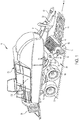
- Fig. 1
- is a perspective side view of a machine, such as a baler, having a feed system in accordance with one implementation of the present disclosure.
- Fig. 2A
- is a detailed perspective view of the feed system of the baler of
FIG. 1 . - Fig. 2B
- is a detailed side view of the feed system of
FIG. 2A . - Fig. 2C removed.
- is a perspective view of the feed system of
FIG. 2A with the feed pan - Fig 3A-C
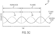
- illustrate the rotational movement of the first rotary drive and of the second rotary drive during the baling process.
- Before any embodiments of the disclosure are explained in detail, it is to be understood that the disclosure is not limited in its application to the details of the formation and arrangement of components set forth in the following description or illustrated in the accompanying drawings. The disclosure is capable of supporting other implementations and of being practiced or of being carried out in various ways. Directions such as clockwise and counterclockwise used herein are for illustrative purposes only.
- Referring to
FIGS. 1 and2A , abaler 10 includes aframe 14, a set ofwheels 18 mounted on theframe 14, afeed system 22 coupled to theframe 14, and acompression system 26 to receive and compresscrop material 46 provided by thefeed system 22. Thecompression system 26, in turn, is a square baler and includes a reciprocating piston (not shown) positioned within acompression chamber 206 able to formbales 36 of a crop, such as hay, straw, or other biomasses. - In the illustrated embodiment, the
frame 14 of thebaler 10 includes atow bar 38 extending from theframe 14 and connectable to a towing vehicle (not shown), such as an agricultural tractor or other vehicle. Thebaler 10 also includes apower takeoff shaft 42 connectable to the towing vehicle to transmit a rotating drive force from the towing vehicle to the various components of thebaler 10. In other implementations, thebaler 10 may have a dedicated power supply and/or prime mover (not shown), such as an engine, motor, battery, fuel cell, etc., for driving thewheels 18 and for driving and/or powering the various components of the baler 10 (described below). - As shown in
FIGS. 1 and2A-2B , thefeed system 22 of thebaler 10 is configured to pick upcrop material 46 from asupport surface 50 and convey thecrop material 46 to thecompression system 26 for final densification and bale forming. Thefeed system 22 includes apickup assembly 54 defining aninlet 58 for receiving thecrop material 46 from the support surface 50 (i.e., a farm field), and alifter assembly 66 to convey a metered amount of thecrop material 46 into thecompression system 26. - The
pickup assembly 54 of thefeed system 22 includes aroller baffle 70 oriented generally transverse to the direction of travel T (e.g., across the width) of thebaler 10, and apickup plate 74 disposed adjacent theroller baffle 70 for conveying thecrop 46 towards acutter assembly 62. Thepickup plate 74 may include a continuous loop surface (e.g., a moving conveyor) driven for conveying thecrop material 46, or other suitable mechanisms. - In some implementations, the
feed system 22 may also include acutter assembly 62 having anelongated cutter shaft 78 oriented generally transverse to the direction of travel T of thebaler 10 and carrying a series of cutters orblades 82 for cutting thecrop 46. Thecutter assembly 62 rotates about acentral axis 86 of thecutter shaft 78 that is oriented generally transverse to the direction of travel T and substantially parallel to theroller baffle 70. During use, thecutter assembly 62 is configured to cut or shorten the length of thecrop material 46 before being passed onto thelifter assembly 66. In other implementations, thepickup assembly 54 andcutter assembly 62 may have different constructions and orientations with respect to thebaler 10 and with respect to each other. - Illustrated in
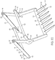
FIGS. 1 , and2A-2C , thelifter assembly 66 of thefeed system 22 includes afeed pan 90 at least partially defining apre-compression chamber 94 therein, alifting fork 98 to engagecrop material 46 positioned within thepre-compression chamber 94, and adrive assembly 100 to maneuver thelifting fork 98 during the baling operation. During use, thelifter assembly 66 is operable in a "packing mode" of operation, wherecrop material 46 is packed into thepre-compression chamber 94, and a "filling mode" of operation, wherecrop material 46 is ejected from thepre-compression chamber 94. - Illustrated in
FIGS. 2A and2B , thefeed pan 90 of thelifter assembly 66 is substantially arcuate in shape having acurved bottom wall 92, atop wall 96 spaced a distance from and extending substantially parallel thebottom wall 92, and a pair ofside walls 102 extending between thetop wall 96 and thebottom wall 92 to at least partially define thepre-compression chamber 94 therebetween. Thewalls feed pan 90 also form a first end or inlet 106 proximate thecutter assembly 62, and a second end oroutlet 110 opposite theinlet 106 and proximate thecompression chamber 206 of thecompression system 26. In the illustrated implementation, thepre-compression chamber 94 extends between theinlet 106 andoutlet 110 of thefeed pan 90 forming an elongated channel that is open on both ends. During use,crop material 46 enters thepre-compression chamber 94 via theinlet 106, travels along the length of thepre-compression chamber 94, and is ejected via the outlet 110 (i.e., into the compression chamber 206). - In the illustrated implementation, the
inlet 106 of thefeed pan 90 is oriented at an angle with respect to theoutlet 110 such thatcrop material 46 that enters thepre-compression chamber 94 in a first direction A (i.e., substantially opposite the direction of travel T) is then ejected from theoutlet 110 in a second direction B, different than the first direction A. More specifically, theoutlet 110 is oriented substantially 90 degrees from theinlet 106. In alternative implementations, theinlet 106 may be substantially parallel to theoutlet 110. Thefeed pan 90 also includes a plurality ofslots 114 defined by thetop wall 96 and providing access to thepre-compression chamber 94. Theslots 114 are generally elongated in shape and extend along the length of thefeed pan 90 between theinlet 106 and theoutlet 110. In the illustrated implementation, eachslot 114 is sized to allow acorresponding tooth 150 of thelifting fork 98 to pass therethrough. - With continued reference to
FIGS. 2A-2C , thelifting fork 98 of thelifter assembly 66 includes abody 124 and a plurality ofteeth 150 each extending from thebody 124 to adistal end 154. Thebody 124 of thelifting fork 98 includes a pair ofside members 130 positioned proximate theside walls 102 of thefeed pan 90. Theside members 130 of thelifting fork 98 are substantially elongated in shape and include afirst end 134, and asecond end 138 opposite thefirst end 134. Eachside member 130 also includes afirst mounting point 142 positioned proximate the center of theside member 130, and asecond mounting point 146 positioned proximate thefirst end 134 of theside member 130. In the illustrated implementation, eachside member 130 forms a slight "V" shape thereby positioning thesecond end 138 slightly ahead of the first andsecond mounting points side members 130 may be straight or formed as necessary to appropriately position thesecond end 138 with respect to thefirst mounting point 142 and thesecond mounting point 146. - In the illustrated implementation, the
body 124 of thelifting fork 98 also includes one ormore cross-members 120. More specifically, thebody 124 includes asingle cross-member 120 oriented substantially transverse to the direction of travel T and coupled to eachside member 130 proximate thesecond end 138 thereof. When assembled, thecross-member 120 acts as a support element providing rigidity and strength to thelifting fork 98 while also acting as a mounting point for the plurality of teeth 150 (described below). While the illustrated implementation includes asingle cross-member 120 positioned proximate thesecond end 138, it is understood that more orfewer cross-members 120 may be included as needed to provide sufficient rigidity to the device. - The
teeth 150 of the liftingfork 98 are coupled to and spaced evenly along the width of the cross-member 120. In the illustrated implementation, theteeth 150 are positioned such that eachtooth 150 substantially aligns with a corresponding one of theslots 114 of thefeed pan 90. As such, when thesecond end 138 of the liftingfork 98 is maneuvered toward thefeed pan 90, the distal ends 154 of eachtooth 150 are able to pass through theirrespective slots 114 and into thepre-compression chamber 94. - During use, the
teeth 150 of the liftingfork 98 travel alongdifferent lifting paths 132, 136 causing theteeth 150 to selectively engage and manipulate thecrop material 46 positioned within thepre-compression chamber 94. Depending upon the contour of the lifting path being followed, theteeth 150 of the liftingfork 98 may affect the behavior of thecrop material 46 in different ways. In the illustrated implementation, theteeth 150 are movable along a first lifting path 132, where theteeth 150draw crop material 46 into thepre-compression chamber 94 through the inlet 106 (generally corresponding to the packing mode of operation), or asecond lifting path 136, where theteeth 150eject crop material 46 out of thepre-compression chamber 94 through the outlet 110 (generally corresponding to the filling mode of operation). - The first lifting path 132 is generally elliptical in shape originating proximate the
inlet 106 at aninitial point 156. The first path 132 extends along the curved contour of thebottom wall 92 toward theoutlet 110 for approximately half the chamber's length. The first path 132 then exits thepre-compression chamber 94 through thetop wall 96 and travels outside thepre-compression chamber 94 toward theinlet 106. The path 132 then re-enters thepre-compression chamber 94 through thetop wall 96 and returns to theinitial point 156 to complete the circuit. By only traveling along a portion of the length of thepre-compression chamber 94, theteeth 150 of the liftingfork 98draw crop material 46 into thepre-compression chamber 94 without causing thecrop material 46 to exit via theoutlet 110. As such, the mass ofcrop material 46 positioned within thepre-compression chamber 94 increases by a pre-determined amount each time the liftingfork 98 completes a cycle about the first path 132. - The
second lifting path 136 is generally elliptical in shape originating proximate theinlet 106 at the sameinitial point 156 as the first lifting path 132. Thesecond path 136 extends along the curved contour of thebottom wall 92 toward theoutlet 110 for approximately the chamber's entire length. Thesecond path 136 then exits thepre-compression chamber 94 proximate theoutlet 110 and travels outside thepre-compression chamber 94 back toward theinlet 106. Thepath 136 then re-enters thepre-compression chamber 94 and returns to theinitial point 156 to complete the circuit. By traveling approximately the entire length of thepre-compression chamber 94, theteeth 150 of the liftingfork 98force crop material 46 positioned within thepre-compression chamber 94 through theoutlet 110 and into thecompression chamber 206 of thecompression system 26. As such, thepre-compression chamber 94 is substantially emptied each time the liftingfork 98 completes a cycle about thesecond path 136. - Illustrated in
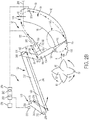
FIGS. 2B and2C , thedrive assembly 100 of thelifter assembly 66 includes a first output shaft orrotary drive 162 rotatable about a first axis ofrotation 166, and a second output shaft orrotary drive 170 rotatable about a second axis ofrotation 174. Eachoutput shaft takeoff shaft 42, and the like) and can be controlled independently of one another. The first andsecond output shafts fork 98 such that the relative rotational positions of the twooutput shafts fork 98 with respect to thepre-compression chamber 94. As such, manipulating the rotational position of thefirst output shaft 162, thesecond output shaft 170, or a combination thereof forces the liftingfork 98 to move to a predetermined location. In the illustrated implementation, thefirst axis 166 of thefirst output shaft 162 is substantially parallel to thesecond axis 174 of thesecond output shaft 170 such that both the first andsecond output shafts baler 10. However, in alternative implementations, the relative layout of eachoutput shaft - The
drive assembly 100 also includes a gearbox (not shown) configured to receive input from thepower takeoff shaft 42 and to selectively convey that power to both the first andsecond output shafts power takeoff shaft 42 to the first andsecond output shafts output shaft output shafts first output shaft 162, thesecond output shaft 170, and thetakeoff shaft 42. In other implementations, the various gear sets and other elements of thedrive assembly 100 may be positioned in and supported by multiple gearboxes or housings mounted throughout the baler 10 (not shown). For example, a separate gearbox may be included to support each of thefirst output shaft 162, thesecond output shaft 170, and thetakeoff shaft 42. - The
drive assembly 100 also includes afirst drive linkage 178 coupled to and extending between thefirst output shaft 162 and the liftingfork 98. More specifically, thefirst drive linkage 178 of thedrive assembly 100 includes afirst crank arm 186 coupled to and extending between both thefirst output shaft 162 and thefirst mounting point 142 of the liftingfork 98. Thefirst crank arm 186 of thefirst drive linkage 178 includes athird mounting point 190, and afourth mounting point 194 spaced a first crank distance 198 from thethird mounting point 190. When assembled, thethird mounting point 190 of thefirst crank arm 186 is fixedly coupled to thefirst output shaft 162 such that thefirst crank arm 186 and thefirst output shaft 162 rotate together as a unit. Furthermore, thefourth mounting point 194 is pivotably coupled to thefirst mounting point 142 of the liftingfork 98. As such, rotation of thefirst output shaft 162 about thefirst axis 166 causes thefirst mounting point 142 of the liftingfork 98 to travel in a substantially circular path about thefirst axis 166. - The
drive assembly 100 also includes asecond drive linkage 182 coupled to and extending between thesecond output shaft 170 and the liftingfork 98. More specifically, thesecond drive linkage 182 of thedrive assembly 100 includes asecond crank arm 218 coupled to thesecond output shaft 170, and a connectingrod 222 extending between and coupled to both thesecond crank arm 218 and the liftingfork 98. Thesecond crank arm 218 of thesecond drive linkage 182 includes afifth mounting point 226, and asixth mounting point 230 spaced asecond crank distance 234 from thefifth mounting point 226. When assembled, thefifth mounting point 226 of thesecond crank arm 218 is fixedly coupled to thesecond output shaft 170 such that thesecond crank arm 218 and thesecond output shaft 170 rotate together as a unit. As such, rotation of thesecond output shaft 170 about thesecond axis 174 causes thesixth mounting point 230 to travel in a substantially circular path about thesecond axis 174. - The connecting
rod 222 of thesecond drive linkage 182 includes aseventh mounting point 238, and aneighth mounting point 242 spaced a connectingrod distance 246 from theseventh mounting point 238. When assembled, theseventh mounting point 238 of the connectingrod 222 is pivotably coupled to thesixth mounting point 230 of thesecond crank arm 218 causing the two points to remain coincident. Similarly, theeighth mounting point 242 is pivotably coupled to thesecond mounting point 146 of the liftingfork 98 causing those two points to remain coincident. As such, any rotational movement of thesecond output shaft 170 is transmitted tosecond mounting point 146 of the liftingfork 98 via thesecond drive linkage 182. - The
drive assembly 100 also includes afirst clutch 250, in operable communication with thesecond output shaft 170. During use, the clutch 250 is adjustable between an engaged configuration, in which torque from the gearbox and thesecond output shaft 170 are in operable communication causing thesecond output shaft 170 to rotate about thefirst axis 166, and a disengaged configuration, in which the gearbox and thesecond output shaft 170 are not in operable communication and thesecond output shaft 170 remains stationary. Although not illustrated, thedrive assembly 100 may also include a corresponding brake (not shown) to maintain thesecond output shaft 170 in its stationary position when the clutch 250 is disengaged, eliminating the ability of thesecond output shaft 170 to rotate freely on its own. While the illustrated implementation includes asingle clutch 250 associated with thesecond output shaft 170, thedrive assembly 100 may also include a second clutch (not shown) in operable communication with thefirst output shaft 162. - During use, the first and
second output shafts teeth 150 of the liftingfork 98 to reciprocate along a series of unique, generally elliptical-shaped paths. More specifically, referring toFIG. 3A , thedrive assembly 100 is operable in afirst output pattern 210, where theteeth 150 travel along the first lift path 132 (described above), and asecond output pattern 214, where theteeth 150 travel along the second lift path 136 (described above). As such, theoutput shafts second output patterns drive assembly 100 to transition between the packing and filling modes of operation. - When operating in the
first output pattern 210, the clutch 250 is in the disengaged configuration causing power to only be transmitted to thefirst output shaft 162. As such, thefirst output shaft 162 rotates about thefirst axis 166 at a constant, non-zero rotational speed and thesecond output shaft 170 remains stationary (e.g., does not rotate about thesecond axis 174; seeFIG. 3A ). As a result, the relative movement of theoutput shafts second drive linkages fork 98 to move along the first lifting path 132. - In the illustrated implementation, the
second output shaft 170 remains in a common location (e.g., with thefirst crank arm 186 in the six o'clock position) causing the contour of the first lifting path 132 to remain similar for each subsequent cycle. However, in alternative implementations, thesecond output shaft 170 may be moved or re-located to different "rest" locations (e.g., with thefirst crank arm 186 in the six o'clock position for one cycle, then in the nine o'clock position for a subsequent cycle, and the like) in order to allow the user to finely tune or adjust the contour of the first lifting path 132. - When operating in the
second output pattern 214, the clutch 250 is in the engaged configuration causing power to be transmitted to both the first andsecond output shafts second output shafts respective axes output shafts second drive linkages fork 98 to move along thesecond lifting path 136. In the illustrated implementation, both the first andsecond output shafts FIG. 3A ). However, in alternative implementations, the relative speed of the first andsecond output shafts second output pattern 214. - The first and
second output shafts third output pattern 216. When operating in thethird output pattern 210, bothoutput shafts second output shafts rotation output shafts second output shaft 170 rotates at half the rate of the first output shaft 162 (seeFIG. 3B ). As a result, the relative movement of theoutput shafts second drive linkages first zone 220 causes the liftingfork 98 to move along the first lifting path 132 (e.g., in the packing mode of operation), while thesecond zone 224 causes the liftingfork 98 to move along the second lifting path 136 (e.g., in the filling mode of operation). As such, thethird output pattern 216 is able to produce both the first andsecond lifting paths 132, 136 without the need for engaging and disengaging anyclutches 250. When operating in thethird output pattern 216, the relative speed of thefirst output shaft 162 and thesecond output shaft 170 is generally some harmonic of the other (e.g., 2:1, 3:1, 4:1, etc.) so that the two shafts can return to an initial starting position. - The first and
second output shafts fourth output pattern 228. When operating in thefourth output pattern 228, bothoutput shafts second output shafts rotation output shafts FIG. 3C ). As a result, the relative movement of theoutput shafts second drive linkages first zone 232 causes the liftingfork 98 to move along the first lifting path 132 (e.g., the packing mode of operation), while thesecond zone 236 causes the liftingfork 98 to move along the second lifting path 136 (e.g., the filling mode of operation). As such, thefourth output pattern 228, like thefirst output pattern 216, is able to produce both the first andsecond lifting paths 132, 136 without the need for engaging and disengaging anyclutches 250. - Illustrated in
FIG. 2B , thebaler 10 also includes acontroller 254 to monitor and direct the baling process. Thecontroller 254 includes aprocessor 258, amemory unit 262 in operable communication with theprocessor 258, one ormore sensors processor 258, and auser input 278 in operable communication with theprocessor 258. Theprocessor 258 is also in operable communication with various elements of thedrive assembly 100 including, but not limited to, the clutch 250. During use, theprocessor 258 receives signals from the one ormore sensors fork 98 with respect to thepre-compression chamber 94. - In particular, the
baler 10 includes a first crankarm position sensor 266, a second crankarm position sensor 270, and a pre-compressionchamber fill sensor 274. Thesensors controller 254 may also include additional sensors such as, but not limited to, a plunger position sensor (e.g., for the compression system 26). While the sensors of the illustrated implementation are electronic in nature, it is to be understood that in alternative implementations thecontroller 254 and sensors may be mechanical in nature. - The first crank
arm position sensor 266 includes a sensor mounted to thefirst crank arm 186 and configured to measure the relative position of the first crank arm with respect to theframe 14 of the baler 10 (e.g., a first crank position angle). The first crankarm position sensor 266 may include a sensor mounted directly to thefirst crank arm 186, or a sensor mounted on thefirst output shaft 162. Such sensors may include Hall Effect sensors, variable resistance sensors, optical sensors, and the like. - The second crank
arm position sensor 270 includes a position sensor mounted to thesecond crank arm 218 and configured to measure the relative position of the second crank arm with respect to theframe 14 of the baler 10 (e.g., the second crank position angle). The second crankarm position sensor 270 may include a sensor mounted directly to thefirst crank arm 218, or a sensor mounted on the first output shaft 164. Such sensors may include Hall Effect sensors, variable resistance sensors, optical sensors, and the like. - The pre-compression
chamber fill sensor 274 is configured to measure when a sufficient mass ofcrop material 46 is positioned within thepre-compression chamber 94 of thefeed pan 90. The pre-compressionchamber fill sensor 274 may include a micro-switch or infrared eye that is triggered when the crop material level reaches a particular location in thepre-compression chamber 94. In still other implementations, thechamber fill sensor 274 may include a number of mechanical arms or gates that are in mechanical communication with the clutch 250. - During operation, the
processor 258 of thebaler 10 monitors the motion of the first andsecond output shafts fill sensor 274 and outputs signals to the clutch 250 to alternate thelifter assembly 66 between a "packing mode" of operation and a "filling mode" of operation. More specifically, theprocessor 258 begins with thedrive assembly 100 in "packing mode" of operation, whereby the clutch 250 is disengaged causing thedrive assembly 100 to produce thefirst output pattern 210 and theteeth 150 to move along the first lifting path 132. Once theprocessor 258 receives a signal from thefill sensor 274 indicating thepre-compression chamber 94 is full, theprocessor 258 changes thelifter assembly 66 to the "filling mode" of operation by outputting a signal to the clutch 250 causing it to change from the disengaged configuration to the engaged configuration. By doing so, thedrive assembly 100 begins producing thesecond output pattern 214 and theteeth 150 travel along thesecond lifting path 136. - After a single rotation about the
second path 136 by theteeth 150 to evacuate thepre-compression chamber 94, theprocessor 258 sends another signal to the clutch 250 causing it to switch back to the disengaged configuration. By doing so, thedrive assembly 100 returns to producing thefirst output pattern 210 and theteeth 150 travel along the first lifting path 132. - When changing between the first and
second output patterns processor 258 takes into account the position of the liftingfork 98 and the position of the plunger (not shown) within the compression chamber 126 to properly time the sending of signals to the clutch 250. For example, switching between thesecond output pattern 214 and thefirst output pattern 210 occurs when the distal ends 154 of theteeth 150 are positioned proximate the initial point 156 (e.g., where both the first path 132 and thesecond path 136 are coincident). Theprocessor 258 must also verify that the compression chamber is not obstructed by the plunger as theteeth 150 move through thesecond lifting path 136. - During operation, the
baler 10 begins with nocrop material 46 in thepre-compression chamber 94 and the liftingassembly 66 in the "packing mode" of operation (described above). As such, the clutch 250 is disengaged causing thedrive assembly 100 to produce thefirst output pattern 210 and theteeth 150 to travel along the first lifting path 132. - As the
baler 10 operates, the forward motion of thebaler 10 in the direction of travel T causescrop material 46 positioned on thesupport surface 50 to come into contact with and be collected by thepickup assembly 54. The collectedcrop material 46 is then processed by thecutter assembly 62 and directed toward theinlet 106 of thepre-compression chamber 94. The liftingfork 98 then engages thecrop material 46 exiting thecutter assembly 62 and directs a portion of thecrop material 46 into thepre-compression chamber 94 with each passing stroke. As the liftingfork 98 continues to cycle along the first path 132, the liftingfork 98 continues to direct portions ofcrop material 46 into thepre-compression chamber 94 causing the mass ofcrop material 46 positioned in thepre-compression chamber 94 to increase. - Once the mass of
crop material 46 positioned within thepre-compression chamber 94 reaches a predetermined level, thechamber fill sensor 274 sends a signal to thecontroller 254 indicating the pre-compression chamber is full. Thecontroller 254 receives this signal while continuously monitoring the rotational positions of the first andsecond output shafts compression system 26. - With the signal from the
chamber fill sensor 274 received, thecontroller 254 changes thelifter assembly 66 from the packing mode of operation to the filling mode of operation. To do so, thecontroller 254 calculates, via both crankarm position sensors distal end 154 of thetooth 150. Once thedistal end 154 of thetooth 150 is positioned proximate theinitial point 156, thecontroller 254 sends a signal to the clutch 250 causing it to change from the disengaged configuration to the engaged configuration. As described above, doing so causes torque from thepower takeoff shaft 42 to be conveyed to bothoutput shafts drive assembly 100 produces thesecond output pattern 214 and theteeth 150 travel along thesecond lifting path 136. - With the output pattern changed, the subsequent cycle of the lifting
fork 98 follows thesecond path 136 instead of the first path 132. As such, the liftingfork 98 engages thecrop material 46 positioned within thepre-compression chamber 94 and ejects thecrop material 46 through theoutlet 110 and into the compression chamber 126 of thecompression system 26. - After the traveling along the
second path 136, the liftingfork 98 returns to theinitial point 156 whereby theprocessor 258 sends a signal to the clutch 250 causing it to return to the disengaged configuration. By doing so, thedrive assembly 100 produces thefirst output pattern 210, theteeth 150 travel along the first lifting path 132, and the process begins anew.
Claims (15)
- A baler (10) comprising:a frame (14);a compression system (26) coupled to the frame (14), the compression system (26) at least partially defining a compression chamber (206);a feed pan (90) at least partially defining a pre-compression chamber (94), wherein the pre-compression chamber (94) is in operable communication with the compression chamber (206);a first driven output shaft (162) rotatable about a first axis of rotation (166);a second driven output shaft (170) rotatable about a second axis of rotation (174);a lifting fork (98) movable with respect to the pre-compression chamber (94) and at least partially positionable therein, wherein rotation of the first driven output shaft (162), the second driven output shaft (170), or any combination thereof causes the lifting fork (98) to move with respect to the pre-compression chamber (94), andwherein the first driven output shaft (162) is operable independently of the second driven output shaft (170).
- The baler (10) of claim 1, wherein the baler (10) is operable in a first mode of operation wherein the first driven output shaft (162) is configured to rotate about the first axis of rotation (166) and the second driven output shaft (170) is configured to concurrently not rotate about the second axis of rotation (174).
- The baler (10) of claim 1 or 2, wherein the baler (10) is operable in a second mode of operation wherein the first driven output shaft (162) is configured to rotate about the first axis of rotation (166) and the second driven output shaft (170) is configured to concurrently rotate about the second axis of rotation (174).
- The baler (10) of one of the claims 1 to 3, wherein first driven output shaft (162) is in operable communication with the lifting fork (98) via a first linkage assembly (178).
- The baler (10) of claim 4, wherein the first linkage assembly (178) includes a first crank arm (186).
- The baler (10) of one of the claims 1 to 5, wherein the second driven output shaft (170) is in operable communication with the lifting fork (98) via a second linkage assembly (182).
- The baler (10) of claim 6, wherein the second linkage assembly (182) includes a second crank arm (218) and a connecting arm (222) pivotably coupled to the crank arm (218).
- The baler (10) of one of the claims 2 to 7, further comprising a controller (254) in operable communication with the first driven output shaft (162) and the second driven output shaft (170), wherein the controller (254) is configured to operate in the first mode of operation and the second mode of operation.
- The baler (10) of one of the claims 1 to 8, further comprising a fill sensor (274) configured to detect when the pre-compression chamber (94) is full of crop material.
- The baler (10) of claim 9, wherein the controller (254) is configured to switch between the first and second modes of operation based at least in part on a signal from the fill sensor (274).
- The baler (10) of one of the claims 1 to 10, further comprising a power source (42), and wherein at least one of the first driven output shaft (162) and the second driven output shaft (170) are in operable communication with the power source (42) via a clutch (250).
- The baler (10) of one of the claims 1 to 11, wherein the lifting fork (98) is movable with respect to the pre-compression chamber (94) along a first lifting path (132) and along a second lifting path (136) different than the first lifting path (132); wherein movement of at least one of the first driven output shaft (162) or the second driven output shaft (170) causes the lifting fork (98) to move with respect to the pre-compression chamber (94) such that when the first driven output shaft (162) rotates about the first axis of rotation (166) and the second driven output shaft (170) concurrently does not rotate about the second axis of rotation (174) the lifting fork (98) travels along the first lifting path (132), and when the first driven output shaft (162) rotates about the first axis of rotation (166) and the second driven output shaft (170) concurrently rotates about the second axis of rotation (174) the lifting fork (98) travels along the second lifting path (136).
- The baler (10) of claim 12, wherein the first lifting path (132) is configured to correspond with a packing mode of operation and the second lifting path (136) is configured to correspond with a filling mode of operation.
- The baler (10)) of one of the claims 1 to 13, wherein when the first driven output shaft (162) rotates about the first axis of rotation (166) and the second driven output shaft (170) concurrently rotates about the second axis of rotation (174), the first and second driven output shafts (162, 170) rotate in the same direction.
- The baler (10)) of one of the claims 1 to 14, wherein when the first driven output shaft (162) rotates about the first axis of rotation (166) and the second driven output shaft (170) concurrently rotates about the second axis of rotation (174), the first and second driven output shafts (162, 170) rotate at the same speed.
Applications Claiming Priority (1)
| Application Number | Priority Date | Filing Date | Title |
|---|---|---|---|
| US15/692,882 US10588270B2 (en) | 2017-08-31 | 2017-08-31 | Baler feed system |
Publications (2)
| Publication Number | Publication Date |
|---|---|
| EP3456177A1 true EP3456177A1 (en) | 2019-03-20 |
| EP3456177B1 EP3456177B1 (en) | 2020-09-02 |
Family
ID=63452492
Family Applications (1)
| Application Number | Title | Priority Date | Filing Date |
|---|---|---|---|
| EP18191895.4A Active EP3456177B1 (en) | 2017-08-31 | 2018-08-31 | Baler |
Country Status (2)
| Country | Link |
|---|---|
| US (1) | US10588270B2 (en) |
| EP (1) | EP3456177B1 (en) |
Cited By (1)
| Publication number | Priority date | Publication date | Assignee | Title |
|---|---|---|---|---|
| EP4331346A1 (en) * | 2022-08-17 | 2024-03-06 | Kuhn-Geldrop B.V. | Square baler |
Families Citing this family (2)
| Publication number | Priority date | Publication date | Assignee | Title |
|---|---|---|---|---|
| CN110199688A (en) * | 2019-06-28 | 2019-09-06 | 大连理工大学 | A kind of industrial hemp field pickup, pier root, packing and inlet composite machine equipment |
| DE102020002580B4 (en) * | 2020-04-29 | 2024-01-25 | Maschinenfabrik Bernard Krone GmbH & Co. KG | Conveying and collecting device with a drivable conveying and collecting unit and agricultural crop press with the conveying and collecting device |
Citations (3)
| Publication number | Priority date | Publication date | Assignee | Title |
|---|---|---|---|---|
| FR2863821A1 (en) * | 2003-12-19 | 2005-06-24 | Claas Selbstfahr Erntemasch | Crop packing and filling determining device for agricultural bale press, has sensor arranged along width of feeder channel for detecting different densities of crops, where sensor locks or allows movement of crop in channel |
| WO2013083519A1 (en) * | 2011-12-04 | 2013-06-13 | Cnh Belgium N.V. | Combined packer and stuffer means |
| EP3001894A1 (en) * | 2014-09-29 | 2016-04-06 | Deere & Company | Crop sensing system |
Family Cites Families (16)
| Publication number | Priority date | Publication date | Assignee | Title |
|---|---|---|---|---|
| FR2542969B1 (en) * | 1983-03-22 | 1986-03-14 | Rivierre Casalis | PISTON PRESS FOR FORMING FORAGE BALLS |
| EP0636308B1 (en) | 1993-07-23 | 1999-03-03 | New Holland Belgium N.V. | Baler stuffer mechanism |
| DE19531240A1 (en) * | 1995-08-25 | 1997-02-27 | Same Spa | Baler, especially self-propelled large baler |
| DE19709604A1 (en) | 1997-03-08 | 1998-09-10 | Claas Usines France | Method and device for fine adjustment of motion sequences on big balers |
| US6385952B1 (en) * | 2000-12-04 | 2002-05-14 | Agco Corporation | In-line rectangular baler having improved dual purpose stuffer |
| DE20104700U1 (en) * | 2001-03-19 | 2001-06-13 | Kverneland Geldrop B.V., Geldrop | Piston press |
| ITTO20050115A1 (en) | 2005-02-25 | 2006-08-26 | Supertino S R L | PRESS FOR BALLE SQUARE |
| EP2496069B1 (en) * | 2009-11-02 | 2013-08-28 | Lely Patent N.V. | Stuffing device |
| NL1038109C2 (en) * | 2010-06-22 | 2012-01-23 | Forage Innovations Bv | Tine control for balers. |
| GB201113945D0 (en) | 2010-12-15 | 2011-09-28 | Agco Corp | Variable density pre-compression chamber |
| BE1019995A3 (en) * | 2011-05-30 | 2013-03-05 | Cnh Belgium Nv | A SQUARE BALL PRESS WITH A FILLER. |
| BE1021159B1 (en) * | 2013-08-01 | 2015-10-30 | Cnh Industrial Belgium Nv | AGRICULTURAL RECTANGULAR BALER PRESS AND METHOD FOR USE |
| US9736988B2 (en) | 2014-01-30 | 2017-08-22 | Deere & Company | Baler plunger-position sensor assembly and method |
| BE1023069B1 (en) * | 2015-10-20 | 2016-11-16 | Cnh Industrial Belgium Nv | AGRICULTURAL BALL PRESS |
| BE1023621B1 (en) | 2016-04-08 | 2017-05-18 | Cnh Industrial Belgium Nv | RESOURCE FOR A AGRICULTURAL BALL PRESS WITH ANTICIPATING SCHEME BACKGROUND OF THE INVENTION |
| BE1023943B1 (en) * | 2016-04-11 | 2017-09-15 | Cnh Industrial Belgium Nv | RECTANGULAR BALL PRESS WITH IMPROVED FULL PROGRAM MECHANISM |
-
2017
- 2017-08-31 US US15/692,882 patent/US10588270B2/en active Active
-
2018
- 2018-08-31 EP EP18191895.4A patent/EP3456177B1/en active Active
Patent Citations (3)
| Publication number | Priority date | Publication date | Assignee | Title |
|---|---|---|---|---|
| FR2863821A1 (en) * | 2003-12-19 | 2005-06-24 | Claas Selbstfahr Erntemasch | Crop packing and filling determining device for agricultural bale press, has sensor arranged along width of feeder channel for detecting different densities of crops, where sensor locks or allows movement of crop in channel |
| WO2013083519A1 (en) * | 2011-12-04 | 2013-06-13 | Cnh Belgium N.V. | Combined packer and stuffer means |
| EP3001894A1 (en) * | 2014-09-29 | 2016-04-06 | Deere & Company | Crop sensing system |
Cited By (1)
| Publication number | Priority date | Publication date | Assignee | Title |
|---|---|---|---|---|
| EP4331346A1 (en) * | 2022-08-17 | 2024-03-06 | Kuhn-Geldrop B.V. | Square baler |
Also Published As
| Publication number | Publication date |
|---|---|
| US20190059230A1 (en) | 2019-02-28 |
| US10588270B2 (en) | 2020-03-17 |
| EP3456177B1 (en) | 2020-09-02 |
Similar Documents
| Publication | Publication Date | Title |
|---|---|---|
| EP3456177B1 (en) | Baler | |
| EP3158852B1 (en) | Rotor feeder unit for agricultural machines | |
| US4569282A (en) | Plunger hay baler | |
| EP3078259B1 (en) | Synchronization mechanism | |
| US5768872A (en) | Baler with adjustable feed device | |
| EP2735223B1 (en) | Self-propelled mower-conditioner | |
| EP3662743B1 (en) | An agricultural baler | |
| EP3078257B1 (en) | Plunger and pre-compression chamber link | |
| EP3308630B1 (en) | Baler | |
| US10338088B2 (en) | Baling chamber sensor | |
| EP3219196B1 (en) | Baling chamber sensor | |
| BR112014013527B1 (en) | RECTANGULAR TYPE AGRICULTURAL BALDER AND METHOD FOR REDUCING PEAK SPEEDS OF AGRICULTURAL BULK FEEDING DEVICES | |
| US20200077595A1 (en) | Baler with adjustable pre-compression chamber | |
| EP3804500B1 (en) | A baling machine including a pre-baling chamber rotative packer/stuffer | |
| BE1026244B1 (en) | INTELLIGENT BALL FORMATION | |
| US4011710A (en) | Baler with double-acting plunger | |
| CN202197559U (en) | Self-walking type wheat and rice harvesting and paving machine | |
| EP3308632B1 (en) | Baler | |
| JP5057575B2 (en) | Harvesting machine | |
| JP3582515B2 (en) | General purpose combine | |
| CN114643604A (en) | Quick slicer is used in cake processing | |
| CN104823612A (en) | Transmission mechanism of corn thresher and all-purpose threshing and hulling machine | |
| JP3582516B2 (en) | General purpose combine | |
| US20180098505A1 (en) | Baler with lockout valve | |
| US842578A (en) | Baling-press. |
Legal Events
| Date | Code | Title | Description |
|---|---|---|---|
| PUAI | Public reference made under article 153(3) epc to a published international application that has entered the european phase |
Free format text: ORIGINAL CODE: 0009012 |
|
| STAA | Information on the status of an ep patent application or granted ep patent |
Free format text: STATUS: THE APPLICATION HAS BEEN PUBLISHED |
|
| AK | Designated contracting states |
Kind code of ref document: A1 Designated state(s): AL AT BE BG CH CY CZ DE DK EE ES FI FR GB GR HR HU IE IS IT LI LT LU LV MC MK MT NL NO PL PT RO RS SE SI SK SM TR |
|
| AX | Request for extension of the european patent |
Extension state: BA ME |
|
| STAA | Information on the status of an ep patent application or granted ep patent |
Free format text: STATUS: REQUEST FOR EXAMINATION WAS MADE |
|
| 17P | Request for examination filed |
Effective date: 20190920 |
|
| RBV | Designated contracting states (corrected) |
Designated state(s): AL AT BE BG CH CY CZ DE DK EE ES FI FR GB GR HR HU IE IS IT LI LT LU LV MC MK MT NL NO PL PT RO RS SE SI SK SM TR |
|
| GRAP | Despatch of communication of intention to grant a patent |
Free format text: ORIGINAL CODE: EPIDOSNIGR1 |
|
| STAA | Information on the status of an ep patent application or granted ep patent |
Free format text: STATUS: GRANT OF PATENT IS INTENDED |
|
| INTG | Intention to grant announced |
Effective date: 20191107 |
|
| GRAJ | Information related to disapproval of communication of intention to grant by the applicant or resumption of examination proceedings by the epo deleted |
Free format text: ORIGINAL CODE: EPIDOSDIGR1 |
|
| STAA | Information on the status of an ep patent application or granted ep patent |
Free format text: STATUS: REQUEST FOR EXAMINATION WAS MADE |
|
| GRAP | Despatch of communication of intention to grant a patent |
Free format text: ORIGINAL CODE: EPIDOSNIGR1 |
|
| STAA | Information on the status of an ep patent application or granted ep patent |
Free format text: STATUS: GRANT OF PATENT IS INTENDED |
|
| INTC | Intention to grant announced (deleted) | ||
| INTG | Intention to grant announced |
Effective date: 20200331 |
|
| GRAS | Grant fee paid |
Free format text: ORIGINAL CODE: EPIDOSNIGR3 |
|
| GRAA | (expected) grant |
Free format text: ORIGINAL CODE: 0009210 |
|
| STAA | Information on the status of an ep patent application or granted ep patent |
Free format text: STATUS: THE PATENT HAS BEEN GRANTED |
|
| AK | Designated contracting states |
Kind code of ref document: B1 Designated state(s): AL AT BE BG CH CY CZ DE DK EE ES FI FR GB GR HR HU IE IS IT LI LT LU LV MC MK MT NL NO PL PT RO RS SE SI SK SM TR |
|
| REG | Reference to a national code |
Ref country code: GB Ref legal event code: FG4D |
|
| REG | Reference to a national code |
Ref country code: AT Ref legal event code: REF Ref document number: 1307719 Country of ref document: AT Kind code of ref document: T Effective date: 20200915 Ref country code: CH Ref legal event code: EP |
|
| REG | Reference to a national code |
Ref country code: DE Ref legal event code: R096 Ref document number: 602018007447 Country of ref document: DE |
|
| REG | Reference to a national code |
Ref country code: IE Ref legal event code: FG4D |
|
| REG | Reference to a national code |
Ref country code: LT Ref legal event code: MG4D |
|
| PG25 | Lapsed in a contracting state [announced via postgrant information from national office to epo] |
Ref country code: FI Free format text: LAPSE BECAUSE OF FAILURE TO SUBMIT A TRANSLATION OF THE DESCRIPTION OR TO PAY THE FEE WITHIN THE PRESCRIBED TIME-LIMIT Effective date: 20200902 Ref country code: HR Free format text: LAPSE BECAUSE OF FAILURE TO SUBMIT A TRANSLATION OF THE DESCRIPTION OR TO PAY THE FEE WITHIN THE PRESCRIBED TIME-LIMIT Effective date: 20200902 Ref country code: SE Free format text: LAPSE BECAUSE OF FAILURE TO SUBMIT A TRANSLATION OF THE DESCRIPTION OR TO PAY THE FEE WITHIN THE PRESCRIBED TIME-LIMIT Effective date: 20200902 Ref country code: BG Free format text: LAPSE BECAUSE OF FAILURE TO SUBMIT A TRANSLATION OF THE DESCRIPTION OR TO PAY THE FEE WITHIN THE PRESCRIBED TIME-LIMIT Effective date: 20201202 Ref country code: LT Free format text: LAPSE BECAUSE OF FAILURE TO SUBMIT A TRANSLATION OF THE DESCRIPTION OR TO PAY THE FEE WITHIN THE PRESCRIBED TIME-LIMIT Effective date: 20200902 Ref country code: GR Free format text: LAPSE BECAUSE OF FAILURE TO SUBMIT A TRANSLATION OF THE DESCRIPTION OR TO PAY THE FEE WITHIN THE PRESCRIBED TIME-LIMIT Effective date: 20201203 Ref country code: NO Free format text: LAPSE BECAUSE OF FAILURE TO SUBMIT A TRANSLATION OF THE DESCRIPTION OR TO PAY THE FEE WITHIN THE PRESCRIBED TIME-LIMIT Effective date: 20201202 |
|
| REG | Reference to a national code |
Ref country code: NL Ref legal event code: MP Effective date: 20200902 |
|
| REG | Reference to a national code |
Ref country code: AT Ref legal event code: MK05 Ref document number: 1307719 Country of ref document: AT Kind code of ref document: T Effective date: 20200902 |
|
| PG25 | Lapsed in a contracting state [announced via postgrant information from national office to epo] |
Ref country code: RS Free format text: LAPSE BECAUSE OF FAILURE TO SUBMIT A TRANSLATION OF THE DESCRIPTION OR TO PAY THE FEE WITHIN THE PRESCRIBED TIME-LIMIT Effective date: 20200902 Ref country code: PL Free format text: LAPSE BECAUSE OF FAILURE TO SUBMIT A TRANSLATION OF THE DESCRIPTION OR TO PAY THE FEE WITHIN THE PRESCRIBED TIME-LIMIT Effective date: 20200902 Ref country code: LV Free format text: LAPSE BECAUSE OF FAILURE TO SUBMIT A TRANSLATION OF THE DESCRIPTION OR TO PAY THE FEE WITHIN THE PRESCRIBED TIME-LIMIT Effective date: 20200902 |
|
| PG25 | Lapsed in a contracting state [announced via postgrant information from national office to epo] |
Ref country code: PT Free format text: LAPSE BECAUSE OF FAILURE TO SUBMIT A TRANSLATION OF THE DESCRIPTION OR TO PAY THE FEE WITHIN THE PRESCRIBED TIME-LIMIT Effective date: 20210104 Ref country code: RO Free format text: LAPSE BECAUSE OF FAILURE TO SUBMIT A TRANSLATION OF THE DESCRIPTION OR TO PAY THE FEE WITHIN THE PRESCRIBED TIME-LIMIT Effective date: 20200902 Ref country code: CZ Free format text: LAPSE BECAUSE OF FAILURE TO SUBMIT A TRANSLATION OF THE DESCRIPTION OR TO PAY THE FEE WITHIN THE PRESCRIBED TIME-LIMIT Effective date: 20200902 Ref country code: EE Free format text: LAPSE BECAUSE OF FAILURE TO SUBMIT A TRANSLATION OF THE DESCRIPTION OR TO PAY THE FEE WITHIN THE PRESCRIBED TIME-LIMIT Effective date: 20200902 Ref country code: SM Free format text: LAPSE BECAUSE OF FAILURE TO SUBMIT A TRANSLATION OF THE DESCRIPTION OR TO PAY THE FEE WITHIN THE PRESCRIBED TIME-LIMIT Effective date: 20200902 |
|
| PG25 | Lapsed in a contracting state [announced via postgrant information from national office to epo] |
Ref country code: IS Free format text: LAPSE BECAUSE OF FAILURE TO SUBMIT A TRANSLATION OF THE DESCRIPTION OR TO PAY THE FEE WITHIN THE PRESCRIBED TIME-LIMIT Effective date: 20210102 Ref country code: ES Free format text: LAPSE BECAUSE OF FAILURE TO SUBMIT A TRANSLATION OF THE DESCRIPTION OR TO PAY THE FEE WITHIN THE PRESCRIBED TIME-LIMIT Effective date: 20200902 Ref country code: AT Free format text: LAPSE BECAUSE OF FAILURE TO SUBMIT A TRANSLATION OF THE DESCRIPTION OR TO PAY THE FEE WITHIN THE PRESCRIBED TIME-LIMIT Effective date: 20200902 Ref country code: AL Free format text: LAPSE BECAUSE OF FAILURE TO SUBMIT A TRANSLATION OF THE DESCRIPTION OR TO PAY THE FEE WITHIN THE PRESCRIBED TIME-LIMIT Effective date: 20200902 |
|
| REG | Reference to a national code |
Ref country code: DE Ref legal event code: R097 Ref document number: 602018007447 Country of ref document: DE |
|
| PG25 | Lapsed in a contracting state [announced via postgrant information from national office to epo] |
Ref country code: SK Free format text: LAPSE BECAUSE OF FAILURE TO SUBMIT A TRANSLATION OF THE DESCRIPTION OR TO PAY THE FEE WITHIN THE PRESCRIBED TIME-LIMIT Effective date: 20200902 |
|
| PLBE | No opposition filed within time limit |
Free format text: ORIGINAL CODE: 0009261 |
|
| STAA | Information on the status of an ep patent application or granted ep patent |
Free format text: STATUS: NO OPPOSITION FILED WITHIN TIME LIMIT |
|
| 26N | No opposition filed |
Effective date: 20210603 |
|
| PG25 | Lapsed in a contracting state [announced via postgrant information from national office to epo] |
Ref country code: SI Free format text: LAPSE BECAUSE OF FAILURE TO SUBMIT A TRANSLATION OF THE DESCRIPTION OR TO PAY THE FEE WITHIN THE PRESCRIBED TIME-LIMIT Effective date: 20200902 Ref country code: DK Free format text: LAPSE BECAUSE OF FAILURE TO SUBMIT A TRANSLATION OF THE DESCRIPTION OR TO PAY THE FEE WITHIN THE PRESCRIBED TIME-LIMIT Effective date: 20200902 |
|
| PG25 | Lapsed in a contracting state [announced via postgrant information from national office to epo] |
Ref country code: IT Free format text: LAPSE BECAUSE OF FAILURE TO SUBMIT A TRANSLATION OF THE DESCRIPTION OR TO PAY THE FEE WITHIN THE PRESCRIBED TIME-LIMIT Effective date: 20200902 |
|
| REG | Reference to a national code |
Ref country code: CH Ref legal event code: PL |
|
| PG25 | Lapsed in a contracting state [announced via postgrant information from national office to epo] |
Ref country code: MC Free format text: LAPSE BECAUSE OF FAILURE TO SUBMIT A TRANSLATION OF THE DESCRIPTION OR TO PAY THE FEE WITHIN THE PRESCRIBED TIME-LIMIT Effective date: 20200902 |
|
| REG | Reference to a national code |
Ref country code: BE Ref legal event code: MM Effective date: 20210831 |
|
| PG25 | Lapsed in a contracting state [announced via postgrant information from national office to epo] |
Ref country code: LI Free format text: LAPSE BECAUSE OF NON-PAYMENT OF DUE FEES Effective date: 20210831 Ref country code: CH Free format text: LAPSE BECAUSE OF NON-PAYMENT OF DUE FEES Effective date: 20210831 |
|
| PG25 | Lapsed in a contracting state [announced via postgrant information from national office to epo] |
Ref country code: LU Free format text: LAPSE BECAUSE OF NON-PAYMENT OF DUE FEES Effective date: 20210831 |
|
| PG25 | Lapsed in a contracting state [announced via postgrant information from national office to epo] |
Ref country code: IE Free format text: LAPSE BECAUSE OF NON-PAYMENT OF DUE FEES Effective date: 20210831 Ref country code: BE Free format text: LAPSE BECAUSE OF NON-PAYMENT OF DUE FEES Effective date: 20210831 |
|
| GBPC | Gb: european patent ceased through non-payment of renewal fee |
Effective date: 20220831 |
|
| PG25 | Lapsed in a contracting state [announced via postgrant information from national office to epo] |
Ref country code: NL Free format text: LAPSE BECAUSE OF NON-PAYMENT OF DUE FEES Effective date: 20200923 Ref country code: CY Free format text: LAPSE BECAUSE OF FAILURE TO SUBMIT A TRANSLATION OF THE DESCRIPTION OR TO PAY THE FEE WITHIN THE PRESCRIBED TIME-LIMIT Effective date: 20200902 |
|
| PG25 | Lapsed in a contracting state [announced via postgrant information from national office to epo] |
Ref country code: HU Free format text: LAPSE BECAUSE OF FAILURE TO SUBMIT A TRANSLATION OF THE DESCRIPTION OR TO PAY THE FEE WITHIN THE PRESCRIBED TIME-LIMIT; INVALID AB INITIO Effective date: 20180831 |
|
| PG25 | Lapsed in a contracting state [announced via postgrant information from national office to epo] |
Ref country code: GB Free format text: LAPSE BECAUSE OF NON-PAYMENT OF DUE FEES Effective date: 20220831 |
|
| PG25 | Lapsed in a contracting state [announced via postgrant information from national office to epo] |
Ref country code: MK Free format text: LAPSE BECAUSE OF FAILURE TO SUBMIT A TRANSLATION OF THE DESCRIPTION OR TO PAY THE FEE WITHIN THE PRESCRIBED TIME-LIMIT Effective date: 20200902 |
|
| PG25 | Lapsed in a contracting state [announced via postgrant information from national office to epo] |
Ref country code: MT Free format text: LAPSE BECAUSE OF FAILURE TO SUBMIT A TRANSLATION OF THE DESCRIPTION OR TO PAY THE FEE WITHIN THE PRESCRIBED TIME-LIMIT Effective date: 20200902 |
|
| PGFP | Annual fee paid to national office [announced via postgrant information from national office to epo] |
Ref country code: DE Payment date: 20250721 Year of fee payment: 8 |
|
| PGFP | Annual fee paid to national office [announced via postgrant information from national office to epo] |
Ref country code: FR Payment date: 20250825 Year of fee payment: 8 |
|
| PG25 | Lapsed in a contracting state [announced via postgrant information from national office to epo] |
Ref country code: TR Free format text: LAPSE BECAUSE OF FAILURE TO SUBMIT A TRANSLATION OF THE DESCRIPTION OR TO PAY THE FEE WITHIN THE PRESCRIBED TIME-LIMIT Effective date: 20200902 |