EP3455979B1 - Techniques for transmitting uplink control information in low latency wireless communications - Google Patents
Techniques for transmitting uplink control information in low latency wireless communications Download PDFInfo
- Publication number
- EP3455979B1 EP3455979B1 EP17718192.2A EP17718192A EP3455979B1 EP 3455979 B1 EP3455979 B1 EP 3455979B1 EP 17718192 A EP17718192 A EP 17718192A EP 3455979 B1 EP3455979 B1 EP 3455979B1
- Authority
- EP
- European Patent Office
- Prior art keywords
- symbol
- tti
- uci
- resource
- resources
- Prior art date
- Legal status (The legal status is an assumption and is not a legal conclusion. Google has not performed a legal analysis and makes no representation as to the accuracy of the status listed.)
- Active
Links
- 238000004891 communication Methods 0.000 title claims description 91
- 238000000034 method Methods 0.000 title claims description 40
- 230000005540 biological transmission Effects 0.000 claims description 51
- 125000004122 cyclic group Chemical group 0.000 claims description 37
- 101000741965 Homo sapiens Inactive tyrosine-protein kinase PRAG1 Proteins 0.000 claims description 4
- 102100038659 Inactive tyrosine-protein kinase PRAG1 Human genes 0.000 claims description 4
- 230000010363 phase shift Effects 0.000 claims description 3
- 238000005516 engineering process Methods 0.000 description 39
- 238000012545 processing Methods 0.000 description 22
- 230000006870 function Effects 0.000 description 17
- 208000037918 transfusion-transmitted disease Diseases 0.000 description 15
- 238000010586 diagram Methods 0.000 description 14
- 239000000969 carrier Substances 0.000 description 9
- 230000008569 process Effects 0.000 description 8
- 230000002776 aggregation Effects 0.000 description 7
- 238000004220 aggregation Methods 0.000 description 7
- 238000013461 design Methods 0.000 description 7
- 230000011664 signaling Effects 0.000 description 6
- 230000001413 cellular effect Effects 0.000 description 5
- 238000001228 spectrum Methods 0.000 description 5
- 230000001360 synchronised effect Effects 0.000 description 5
- 101150071746 Pbsn gene Proteins 0.000 description 4
- 230000003287 optical effect Effects 0.000 description 3
- 238000013468 resource allocation Methods 0.000 description 3
- 230000008054 signal transmission Effects 0.000 description 3
- 244000126211 Hericium coralloides Species 0.000 description 2
- 230000006835 compression Effects 0.000 description 2
- 238000007906 compression Methods 0.000 description 2
- 239000013256 coordination polymer Substances 0.000 description 2
- 230000006837 decompression Effects 0.000 description 2
- 238000001514 detection method Methods 0.000 description 2
- 230000007774 longterm Effects 0.000 description 2
- 230000008520 organization Effects 0.000 description 2
- 230000011218 segmentation Effects 0.000 description 2
- 238000013459 approach Methods 0.000 description 1
- 238000003491 array Methods 0.000 description 1
- 239000003795 chemical substances by application Substances 0.000 description 1
- 238000012937 correction Methods 0.000 description 1
- 230000002349 favourable effect Effects 0.000 description 1
- 239000011521 glass Substances 0.000 description 1
- 238000013507 mapping Methods 0.000 description 1
- 238000010295 mobile communication Methods 0.000 description 1
- 230000004044 response Effects 0.000 description 1
- 230000002441 reversible effect Effects 0.000 description 1
- 238000004904 shortening Methods 0.000 description 1
- 230000003595 spectral effect Effects 0.000 description 1
Images


Classifications
-
- H—ELECTRICITY
- H04—ELECTRIC COMMUNICATION TECHNIQUE
- H04W—WIRELESS COMMUNICATION NETWORKS
- H04W72/00—Local resource management
- H04W72/20—Control channels or signalling for resource management
- H04W72/21—Control channels or signalling for resource management in the uplink direction of a wireless link, i.e. towards the network
-
- H—ELECTRICITY
- H04—ELECTRIC COMMUNICATION TECHNIQUE
- H04L—TRANSMISSION OF DIGITAL INFORMATION, e.g. TELEGRAPHIC COMMUNICATION
- H04L5/00—Arrangements affording multiple use of the transmission path
- H04L5/003—Arrangements for allocating sub-channels of the transmission path
- H04L5/0048—Allocation of pilot signals, i.e. of signals known to the receiver
- H04L5/0051—Allocation of pilot signals, i.e. of signals known to the receiver of dedicated pilots, i.e. pilots destined for a single user or terminal
-
- H—ELECTRICITY
- H04—ELECTRIC COMMUNICATION TECHNIQUE
- H04L—TRANSMISSION OF DIGITAL INFORMATION, e.g. TELEGRAPHIC COMMUNICATION
- H04L5/00—Arrangements affording multiple use of the transmission path
- H04L5/003—Arrangements for allocating sub-channels of the transmission path
- H04L5/0053—Allocation of signaling, i.e. of overhead other than pilot signals
- H04L5/0055—Physical resource allocation for ACK/NACK
-
- H—ELECTRICITY
- H04—ELECTRIC COMMUNICATION TECHNIQUE
- H04L—TRANSMISSION OF DIGITAL INFORMATION, e.g. TELEGRAPHIC COMMUNICATION
- H04L5/00—Arrangements affording multiple use of the transmission path
- H04L5/003—Arrangements for allocating sub-channels of the transmission path
- H04L5/0058—Allocation criteria
- H04L5/0064—Rate requirement of the data, e.g. scalable bandwidth, data priority
Definitions
- Described herein are aspects generally related to communication systems, and more particularly, to communicating feedback in low latency communication systems.
- Wireless communication systems are widely deployed to provide various telecommunication services such as telephony, video, data, messaging, and broadcasts.
- Typical wireless communication systems may employ multiple-access technologies capable of supporting communication with multiple users by sharing available system resources (e.g., bandwidth, transmit power).
- multiple-access technologies include code division multiple access (CDMA) systems, time division multiple access (TDMA) systems, frequency division multiple access (FDMA) systems, orthogonal frequency division multiple access (OFDMA) systems, single-carrier frequency division multiple access (SC-FDMA) systems, and time division synchronous code division multiple access (TD-SCDMA) systems.
- CDMA code division multiple access
- TDMA time division multiple access
- FDMA frequency division multiple access
- OFDMA orthogonal frequency division multiple access
- SC-FDMA single-carrier frequency division multiple access
- TD-SCDMA time division synchronous code division multiple access
- LTE Long Term Evolution
- UMTS Universal Mobile Telecommunications System
- 3GPP Third Generation Partnership Project
- DL downlink
- UL uplink
- MIMO multiple-input multiple-output
- a plurality of UEs served by a particular eNodeB may be scheduled resources for communicating with the eNodeB over one or more channels using transmission time intervals (TTI) on the order of a 1 millisecond subframe.
- TTI transmission time intervals
- LG Electronics "Discussion on PUCCH design for HARQ-ARK in shortened TTI", R1-163520 relates to PUCCH formats for shortened TTI for UL transmission. 3GPP TS 36.211 version 12.1.0 Release 13, chapter 5.4 relates to PUCCH formats and resources.
- ZTE "PUCCH design for shortened TTI”, R1-162403 relates to design of 2-symbol PUCCH for short TTI. Qualcomm Incorporated, R1-163069 relates to uplink design details for TTI shortening and reduced processing time.
- NTT Docomo, Inc., R1-160965 relates to PUSCH and PUCCH in short-TTI.
- EP2942896 relates to efficiently transmitting/receiving uplink signals in a carrier aggregation based wireless communication system.
- WO2016/048595 relates to determining whether to transmit a demodulation reference signal for an uplink control channel in at least one TTI based on an indicator received from a network entity.
- a method for communicating uplink control information (UCI) in low-latency communications includes receiving a resource assignment from an access point to transmit over a first symbol and a second symbol that comprise a first TTI, wherein the resource assignment includes, at least for the first symbol, an indication of one or more consecutive frequency resources in a system bandwidth based on a decimation factor, and transmitting, in the first TTI, a reference signal over the first symbol and a data signal indicating UCI over the second symbol according to the resource assignment.
- UCI uplink control information
- a method for communicating uplink control information (UCI) in low-latency communications includes transmitting a resource assignment for a user equipment to transmit over a first symbol and a second symbol that comprise a first TTI, wherein the resource assignment includes, at least for the first symbol, an indication of one or more consecutive frequency resources in a system bandwidth based on a decimation factor, and receiving, in the first TTI, a reference signal over the first symbol and a data signal indicating UCI over the second symbol according to the resource assignment.
- UCI uplink control information
- an apparatus for wireless communications includes a transceiver for communicating one or more wireless signals via one or more antennas, a memory configured to store instructions, and one or more processors communicatively coupled with the transceiver and the memory.
- the one or more processors are configured to receive one or more resource assignments from an access point to transmit over a first symbol and a second symbol that comprise a first TTI, wherein a resource assignment of the one or more resource assignments includes, at least for the first symbol, an indication of one or more consecutive frequency resources in a system bandwidth based on a decimation factor, and transmit, in the first TTI, a reference signal over the first symbol and a data signal indicating UCI over the second symbol according to the one or more resource assignments.
- an apparatus for wireless communications including a transceiver for communicating one or more wireless signals via one or more antennas, a memory configured to store instructions, and one or more processors communicatively coupled with the transceiver and the memory.
- the one or more processors are configured to transmit one or more resource assignments for a user equipment to transmit over a first symbol and a second symbol that comprise a first TTI, wherein at least one resource assignment of the one or more resource assignments includes, at least for the first symbol, an indication of one or more consecutive frequency resources in a system bandwidth based on a decimation factor, and receive, in the first TTI, a reference signal over the first symbol and a data signal indicating UCI over the second symbol according to the one or more resource assignments.
- an apparatus for wireless communications includes means for receiving one or more resource assignments from an access point to transmit over a first symbol and a second symbol that comprise a first TTI, wherein a resource assignment of the one or more resource assignments includes, at least for the first symbol, an indication of one or more consecutive frequency resources in a system bandwidth based on a decimation factor, and means for transmitting, in the first TTI, a reference signal over the first symbol and a data signal indicating UCI over the second symbol according to the one or more resource assignments.
- an apparatus for wireless communications including means for transmitting one or more resource assignments for a user equipment to transmit over a first symbol and a second symbol that comprise a first TTI, wherein at least one resource assignment of the one or more resource assignments includes, at least for the first symbol, an indication of one or more consecutive frequency resources in a system bandwidth based on a decimation factor, and means for receiving, in the first TTI, a reference signal over the first symbol and a data signal indicating UCI over the second symbol according to the one or more resource assignments.
- a computer-readable medium including computer executable code for wireless communications.
- the code includes code for receiving one or more resource assignments from an access point to transmit over a first symbol and a second symbol that comprise a first TTI, wherein a resource assignment of the one or more resource assignments includes, at least for the first symbol, an indication of one or more consecutive frequency resources in a system bandwidth based on a decimation factor, and code for transmitting, in the first TTI, a reference signal over the first symbol and a data signal indicating UCI over the second symbol according to the one or more resource assignments.
- a computer-readable medium including computer executable code for wireless communications.
- the code includes code for transmitting one or more resource assignments for a user equipment to transmit over a first symbol and a second symbol that comprise a first TTI, wherein at least one resource assignment of the one or more resource assignments includes, at least for the first symbol, an indication of one or more consecutive frequency resources in a system bandwidth based on a decimation factor, and code for receiving, in the first TTI, a reference signal over the first symbol and a data signal indicating UCI over the second symbol according to the one or more resource assignments.
- the one or more aspects comprise the features hereinafter fully described and particularly pointed out in the claims.
- the following description and the annexed drawings set forth in detail certain illustrative features of the one or more aspects. These features are indicative, however, of but a few of the various ways in which the principles of various aspects may be employed, and this description is intended to include all such aspects and their equivalents.
- processors include microprocessors, microcontrollers, digital signal processors (DSPs), field programmable gate arrays (FPGAs), programmable logic devices (PLDs), state machines, gated logic, discrete hardware circuits, and other suitable hardware configured to perform the various functionality described throughout this disclosure.
- DSPs digital signal processors
- FPGAs field programmable gate arrays
- PLDs programmable logic devices
- state machines gated logic, discrete hardware circuits, and other suitable hardware configured to perform the various functionality described throughout this disclosure.
- One or more processors in the processing system may execute software.
- Software shall be construed broadly to mean instructions, instruction sets, code, code segments, program code, programs, subprograms, software modules, applications, software applications, software packages, routines, subroutines, objects, executables, threads of execution, procedures, functions, etc., whether referred to as software, firmware, middleware, microcode, hardware description language, or otherwise.
- the functions described may be implemented in hardware, software, firmware, or any combination thereof. If implemented in software, the functions may be stored on or encoded as one or more instructions or code on a computer-readable medium.
- Computer-readable media includes computer storage media. Storage media may be any available media that can be accessed by a computer.
- such computer-readable media can comprise RAM, ROM, EEPROM, CD-ROM or other optical disk storage, magnetic disk storage or other magnetic storage devices, or any other medium that can be used to carry or store desired program code in the form of instructions or data structures and that can be accessed by a computer.
- Disk and disc includes compact disc (CD), laser disc, optical disc, digital versatile disc (DVD), and floppy disk where disks usually reproduce data magnetically, while discs reproduce data optically with lasers. Combinations of the above should also be included within the scope of computer-readable media.
- a low latency communication technology may be based on a legacy wireless communication technology, such as third generation partnership project (3GPP) long term evolution (LTE), but may utilize different length transmission time intervals (TTI) (e.g., the low latency communication technology may have a shorter TTI duration than the legacy communication technology).
- 3GPP third generation partnership project
- LTE long term evolution
- TTI transmission time intervals
- a legacy LTE technology may utilize a TTI having a duration of a subframe defined in LTE (e.g., 1 millisecond), where ULL LTE technology can be based on a TTI having a duration less than a subframe.
- the TTI and associated duration of ULL LTE can be based on defined portions of a subframe, such as one symbol, two symbols, a subframe slot, etc., where a subframe can have 12-14 symbols, two slots, etc.
- a lower latency in communications is achieved by the shorter, more frequent TTI.
- a demodulation reference signal (DMRS) and control data may be transmitted in each symbol using frequency hopping to provide frequency diversity.
- DMRS demodulation reference signal
- UCI uplink control information
- one of the two symbols may be reserved for DMRS transmissions and the other for data transmissions.
- frequency hopping across multiple symbols may not be usable.
- the symbol used for data transmission may use a cyclic shift selected to indicate UCI.
- resources over the symbol used for data transmission may be assigned to one or more UEs based on a decimation factor to provide the UEs with multiple bits to transmit UCI.
- the resources may be assigned based on UCI payload for a given UE (e.g., whether the UE is to transmit acknowledgement (ACK)/negative-ACK (NACK) feedback, channel quality indicator (CQI) feedback, and/or the like).
- the symbol reserved for DMRS transmission may be similarly divided for assigning frequency resources (e.g., subcarriers, tones, etc.) to the UEs based on the same or a different decimation factor to maintain orthogonality of the DMRS transmissions.
- both symbols may be assigned for transmitting data, and may depend on a reference signal in a previous TTI for channel estimation/demodulation of the data. This can reduce DMRS overhead otherwise caused by allocating one of the two symbols for DMRS transmission in each TTI.
- TTIs having two assigned data symbols may be used to transmit more UCI (e.g., ACK/NACK and CQI as opposed to one or the other) as opposed to a TTI having one or two symbols assigned for reference signals and/or control data.
- UCI e.g., ACK/NACK and CQI as opposed to one or the other
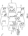
- the wireless communications system 100 includes a plurality of access points (e.g., base stations, eNBs, or WLAN access points) 105, a number of user equipment (UEs) 115, and a core network 130.
- Access points 105 may include a scheduling component 302 configured to allocate resources for communicating with UEs 115 using a ULL communication technology to receive UCI transmissions therefrom.
- UEs 115 may include a communicating component 361 configured to communicate with one or more access points 105 using the ULL communication technology (e.g., ULL LTE) to transmit UCI.
- ULL communication technology e.g., ULL LTE
- Access points 105 may communicate with the UEs 115 under the control of a base station controller (not shown), which may be part of the core network 130 or the certain access points 105 (e.g., base stations or eNBs) in various examples.
- Access points 105 may communicate control information and/or user data with the core network 130 through backhaul links 132.
- the access points 105 may communicate, either directly or indirectly, with each other over backhaul links 134, which may be wired or wireless communication links.
- the wireless communications system 100 may support operation on multiple carriers (waveform signals of different frequencies). Multi-carrier transmitters can transmit modulated signals simultaneously on the multiple carriers.
- each communication link 125 may be a multi-carrier signal modulated according to the various radio technologies described above.
- Each modulated signal may be sent on a different carrier and may carry control information (e.g., reference signals, control channels, etc.), overhead information, data, etc.
- At least a portion of the wireless communications system 100 may be configured to operate on multiple hierarchical layers in which one or more of the UEs 115 and one or more of the access points 105 may be configured to support transmissions on a hierarchical layer that has a reduced latency with respect to another hierarchical layer.
- a UE 115 may communicate with access point 105 on one or more of a first hierarchical layer that supports first layer transmissions using a first TTI (which may relate to a "legacy communication technology") and a second hierarchical layer that supports second layer transmissions using a second TTI, which may be shorter than the first TTI (which may relate to a "ULL communication technology").
- a UE 115 may communicate with an access point 105 on the second hierarchical layer only.
- a UE 115 may belong to a second class of UEs 115 that may communicate on the second hierarchical layer, while another UE 115 may belong to a first class of UEs 115 that may communicate on the first hierarchical layer only.
- access point 105 and UE 115 may communicate on the second hierarchical layer through transmissions of subframes of a second subframe type.
- Access point 105 may transmit communications related to the first or second hierarchical layer only or may transmit communications for both the first and second hierarchical layers.
- communicating component 361 can be configured to prioritize communications received from the access point 105 that relate to the first and second hierarchical layers, as described herein.
- the access points 105 may wirelessly communicate with the UEs 115 via one or more access point antennas. Each of the access points 105 sites may provide communication coverage for a respective coverage area 110.
- access points 105 may be referred to as a base transceiver station, a radio base station, a radio transceiver, a basic service set (BSS), an extended service set (ESS), a NodeB, eNodeB, Home NodeB, a Home eNodeB, or some other suitable terminology.
- the coverage area 110 for a base station may be divided into sectors making up only a portion of the coverage area (not shown).
- the wireless communications system 100 may include access points 105 of different types (e.g., macro, micro, and/or pico base stations).
- the access points 105 may also utilize different radio technologies, such as cellular and/or WLAN radio access technologies (RAT).
- RAT radio access technologies
- the access points 105 may be associated with the same or different access networks or operator deployments.
- the coverage areas of different access points 105, including the coverage areas of the same or different types of access points 105, utilizing the same or different radio technologies, and/or belonging to the same or different access networks, may overlap.
- the wireless communications system 100 may be a Heterogeneous LTE/LTE-A/ULL LTE network in which different types of access points provide coverage for various geographical regions.
- each access point 105 may provide communication coverage for a macro cell, a pico cell, a femto cell, and/or other types of cell.
- Small cells such as pico cells, femto cells, and/or other types of cells may include low power nodes or LPNs.
- a macro cell generally covers a relatively large geographic area (e.g., several kilometers in radius) and may allow unrestricted access by UEs 115 with service subscriptions with the network provider.
- a small cell would generally cover a relatively smaller geographic area and may allow unrestricted access by UEs 115 with service subscriptions with the network provider, for example, and in addition to unrestricted access, may also provide restricted access by UEs 115 having an association with the small cell (e.g., UEs in a closed subscriber group (CSG), UEs for users in the home, and the like).
- An eNB for a macro cell may be referred to as a macro eNB.
- An eNB for a small cell may be referred to as a small cell eNB.
- An eNB may support one or multiple (e.g., two, three, four, and the like) cells.
- the core network 130 may communicate with the eNBs or other access points 105 via one or more backhaul links 132 (e.g., S1 interface, etc.).
- the access points 105 may also communicate with one another, e.g., directly or indirectly via backhaul links 134 (e.g., X2 interface, etc.) and/or via backhaul links 132 (e.g., through core network 130).
- the wireless communications system 100 may support synchronous or asynchronous operation. For synchronous operation, the access points 105 may have similar frame timing, and transmissions from different access points 105 may be approximately aligned in time. For asynchronous operation, the access points 105 may have different frame timing, and transmissions from different access points 105 may not be aligned in time. Furthermore, transmissions in the first hierarchical layer and second hierarchical layer may or may not be synchronized among access points 105.
- the techniques described herein may be used for either synchronous or asynchronous operations.
- the UEs 115 are dispersed throughout the wireless communications system 100, and each UE 115 may be stationary or mobile.
- a UE 115 may also be referred to by those skilled in the art as a mobile station, a subscriber station, a mobile unit, a subscriber unit, a wireless unit, a remote unit, a mobile device, a wireless device, a wireless communications device, a remote device, a mobile subscriber station, an access terminal, a mobile terminal, a wireless terminal, a remote terminal, a handset, a user agent, a mobile client, a client, or some other suitable terminology.
- a UE 115 may be a cellular phone, a personal digital assistant (PDA), a wireless modem, a wireless communication device, a handheld device, a tablet computer, a laptop computer, a cordless phone, a wearable item such as a watch or glasses, a wireless local loop (WLL) station, or the like.
- PDA personal digital assistant
- a UE 115 may be able to communicate with macro eNodeBs, small cell eNodeBs, relays, and the like.
- a UE 115 may also be able to communicate over different access networks, such as cellular or other WWAN access networks, or WLAN access networks.
- the communication links 125 shown in wireless communications system 100 may include uplink (UL) transmissions from a UE 115 to an access point 105, and/or downlink (DL) transmissions, from an access point 105 to a UE 115.
- the downlink transmissions may also be called forward link transmissions while the uplink transmissions may also be called reverse link transmissions.
- the communication links 125 may carry transmissions of each hierarchical layer which, in some examples, may be multiplexed in the communication links 125.
- the UEs 115 may be configured to collaboratively communicate with multiple access points 105 through, for example, Multiple Input Multiple Output (MIMO), carrier aggregation (CA), Coordinated Multi-Point (CoMP), or other schemes.
- MIMO Multiple Input Multiple Output
- CA carrier aggregation
- CoMP Coordinated Multi-Point
- MIMO techniques use multiple antennas on the access points 105 and/or multiple antennas on the UEs 115 to transmit multiple data streams.
- Carrier aggregation may utilize two or more component carriers on a same or different serving cell for data transmission.
- CoMP may include techniques for coordination of transmission and reception by a number of access points 105 to improve overall transmission quality for UEs 115 as well as increasing network and spectrum utilization.
- access points 105 and UEs 115 may utilize carrier aggregation to transmit on multiple carriers.
- access points 105 and UEs 115 may concurrently transmit in a first hierarchical layer, within a frame, one or more subframes each having a first subframe type using two or more separate carriers.
- Each carrier may have a bandwidth of, for example, 20 MHz, although other bandwidths may be utilized.
- a UE 115 may, in certain examples, receive and/or transmit one or more subframes in a second hierarchical layer utilizing a single carrier that has a bandwidth greater than a bandwidth of one or more of the separate carriers.
- a single 80 MHz carrier may be used in the second hierarchical layer.
- the 80 MHz carrier may occupy a portion of the radio frequency spectrum that at least partially overlaps the radio frequency spectrum used by one or more of the four 20 MHz carriers.
- scalable bandwidth for the second hierarchical layer type may be combined techniques to provide shorter RTTs such as described above, to provide further enhanced data rates.
- Each of the different operating modes that may be employed by wireless communications system 100 may operate according to frequency division duplexing (FDD) or time division duplexing (TDD).
- FDD frequency division duplexing
- TDD time division duplexing
- different hierarchical layers may operate according to different TDD or FDD modes.
- a first hierarchical layer may operate according to FDD while a second hierarchical layer may operate according to TDD.
- OFDMA communications signals may be used in the communication links 125 for LTE downlink transmissions for each hierarchical layer
- SC-FDMA single carrier frequency division multiple access
- an access point 105 can assign resources to a UE 115 to communicate using a ULL communication technology having a TTI less than a subframe in duration.
- the ULL communication technology may have at least a two-symbol TTI where one symbol in at least one TTI is used to transmit a reference signal (e.g., DMRS).
- scheduling component 302 can generate a resource assignment for the UE 115 to transmit the reference signal over one or more consecutive frequency resources based on a decimation factor to allow the UE 115 and other UEs to transmit orthogonal reference signals in at least one symbol of at least one TTI.
- scheduling component may generate the resource assignment for the UE 115 to similarly transmit UCI in another symbol (e.g., a second symbol of the TTI, a plurality of symbols of another TTI, etc.) similarly over one or more consecutive frequency resources based on the same or a different decimation factor.
- the UE 115 may select a cyclic shift for transmitting data signals over this symbol to indicate UCI.
- access point 105 may assign a number of frequency resources to the UE 115 based on a payload of the UCI (e.g., more frequency resource assignments may allow for more possible cyclic shifts to indicate more UCI bits).
- the access point 105 may assign all frequency resources of the symbol to the UE 115, or may assign a portion of the frequency resources to the UE 115 and other portions to other UEs.
- FIG. 2 is a diagram illustrating an example of an access network 200 in an LTE or ULL LTE network architecture.
- the access network 200 is divided into a number of cellular regions (cells) 202.
- One or more small cell eNBs 208 may have cellular regions 210 that overlap with one or more of the cells 202.
- the small cell eNBs 208 may provide one or more cells of a lower power class, such as a femto cell (e.g., home eNB (HeNB)), pico cell, micro cell, or remote radio head (RRH).
- the macro eNBs 204 are each assigned to a respective cell 202 and are configured to provide an access point to the core network 130 for all the UEs 206 in the cells 202.
- eNBs 204 and/or 208 may include scheduling component 302 configured to allocate resources for communicating with UEs 206 using a ULL communication technology to receive UCI transmission therefrom.
- UEs 206 may include a communicating component 361 configured to communicate with one or more eNBs 204 and/or 208 using the ULL communication technology (e.g., ULL LTE) to transmit UCI.
- ULL communication technology e.g., ULL LTE
- the eNBs and/or 208 204 can be responsible for all radio related functions including radio bearer control, admission control, mobility control, scheduling, security, and connectivity to one or more components of core network 130.
- the modulation and multiple access scheme employed by the access network 200 may vary depending on the particular telecommunications standard being deployed.
- OFDM may be used on the DL and SC-FDMA may be used on the UL to support both frequency division duplexing (FDD) and time division duplexing (TDD).
- FDD frequency division duplexing
- TDD time division duplexing
- FDD frequency division duplexing
- TDD time division duplexing
- EV-DO Evolution-Data Optimized
- UMB Ultra Mobile Broadband
- EV-DO and UMB are air interface standards promulgated by the 3rd Generation Partnership Project 2 (3GPP2) as part of the CDMA2000 family of standards and employs CDMA to provide broadband Internet access to mobile stations. These concepts may also be extended to Universal Terrestrial Radio Access (UTRA) employing Wideband-CDMA (W-CDMA) and other variants of CDMA, such as TD-SCDMA; Global System for Mobile Communications (GSM) employing TDMA; and Evolved UTRA (E-UTRA), IEEE 802.11 (Wi-Fi), IEEE 802.16 (WiMAX), IEEE 802.20, and Flash-OFDM employing OFDMA.
- UTRA, E-UTRA, UMTS, LTE and GSM are described in documents from the 3GPP organization.
- CDMA2000 and UMB are described in documents from the 3GPP2 organization. The actual wireless communication standard and the multiple access technology employed will depend on the specific application and the overall design constraints imposed on the system.
- the eNBs 204 and/or 208 may have multiple antennas supporting MIMO technology.
- MIMO technology enables the eNBs 204 and/or 208 to exploit the spatial domain to support spatial multiplexing, beamforming, and transmit diversity.
- Spatial multiplexing may be used to transmit different streams of data simultaneously on the same frequency.
- the data steams may be transmitted to a single UE 206 to increase the data rate or to multiple UEs 206 to increase the overall system capacity. This is achieved by spatially precoding each data stream (i.e., applying a scaling of an amplitude and a phase) and then transmitting each spatially precoded stream through multiple transmit antennas on the DL.
- the spatially precoded data streams arrive at the UE(s) 206 with different spatial signatures, which enables each of the UE(s) 206 to recover the one or more data streams destined for that UE 206.
- each UE 206 transmits a spatially precoded data stream, which enables the eNB 204 and/or 208 to identify the source of each spatially precoded data stream.
- Beamforming may be used to focus the transmission energy in one or more directions. This may be achieved by spatially precoding the data for transmission through multiple antennas. To achieve good coverage at the edges of the cell, a single stream beamforming transmission may be used in combination with transmit diversity.
- OFDM is a spread-spectrum technique that modulates data over a number of subcarriers within an OFDM symbol.
- the subcarriers are spaced apart at precise frequencies. The spacing provides "orthogonality" that enables a receiver to recover the data from the subcarriers.
- a guard interval e.g., cyclic prefix
- the UL may use SC-FDMA in the form of a DFT-spread OFDM signal to compensate for high peak-to-average power ratio (PAPR).
- PAPR peak-to-average power ratio
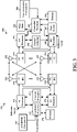
- FIG. 3 is a block diagram of an eNB 310 in communication with a UE 350 in an access network.
- upper layer packets from the core network are provided to a controller/processor 375.
- the controller/processor 375 implements the functionality of the L2 layer.
- the controller/processor 375 provides header compression, ciphering, packet segmentation and reordering, multiplexing between logical and transport channels, and radio resource allocations to the UE 350 based on various priority metrics.
- the controller/processor 375 is also responsible for HARQ operations, retransmission of lost packets, and signaling to the UE 350.
- the transmit (TX) processor 316 implements various signal processing functions for the L1 layer (i.e., physical layer).
- the signal processing functions includes coding and interleaving to facilitate forward error correction (FEC) at the UE 350 and mapping to signal constellations based on various modulation schemes (e.g., binary phase-shift keying (BPSK), quadrature phase-shift keying (QPSK), M-phase-shift keying (M-PSK), M-quadrature amplitude modulation (M-QAM)).
- FEC forward error correction
- BPSK binary phase-shift keying
- QPSK quadrature phase-shift keying
- M-PSK M-phase-shift keying
- M-QAM M-quadrature amplitude modulation
- Each stream is then mapped to an OFDM subcarrier, multiplexed with a reference signal (e.g., pilot signal) in the time and/or frequency domain, and then combined together using an Inverse Fast Fourier Transform (IFFT) to produce a physical channel carrying a time domain OFDM symbol stream.
- the OFDM stream is spatially precoded to produce multiple spatial streams.
- Channel estimates from a channel estimator 374 may be used to determine the coding and modulation scheme, as well as for spatial processing.
- the channel estimate may be derived from a reference signal and/or channel condition feedback transmitted by the UE 350.
- Each spatial stream is then provided to a different antenna 320 via a separate transmitter 318TX.
- Each transmitter 318TX modulates an RF carrier with a respective spatial stream for transmission.
- eNB 310 may include scheduling component 302 configured to allocate resources for communicating with a UE 350 using a ULL communication technology to receive UCI transmissions therefrom.
- scheduling component 302 is shown as coupled with controller/processor 375, substantially any processor of an eNB 310 can provide the functions of the scheduling component 302 and/or its related components described herein (e.g., in conjunction with controller/processor 375, memory 376, or otherwise).
- TX processor 316 and/or RX processor 370 can additionally or alternatively provide one or more functions of scheduling component 302, as described herein.
- each receiver 354RX receives a signal through its respective antenna 352.
- Each receiver 354RX recovers information modulated onto an RF carrier and provides the information to the receive (RX) processor 356.
- the RX processor 356 implements various signal processing functions of the L1 layer.
- the RX processor 356 performs spatial processing on the information to recover any spatial streams destined for the UE 350. If multiple spatial streams are destined for the UE 350, they may be combined by the RX processor 356 into a single OFDM symbol stream.
- the RX processor 356 then converts the OFDM symbol stream from the time-domain to the frequency domain using a Fast Fourier Transform (FFT).
- FFT Fast Fourier Transform
- the symbols on each subcarrier, and the reference signal, is recovered and demodulated by determining the most likely signal constellation points transmitted by the eNB 310. These soft decisions may be based on channel estimates computed by the channel estimator 358. The soft decisions are then decoded and deinterleaved to recover the data and control signals that were originally transmitted by the eNB 310 on the physical channel. The data and control signals are then provided to the controller/processor 359.
- the controller/processor 359 implements the L2 layer.
- the controller/processor can be associated with a memory 360 that stores program codes and data.
- the memory 360 may be referred to as a computer-readable medium.
- the controller/processor 359 provides demultiplexing between transport and logical channels, packet reassembly, deciphering, header decompression, control signal processing to recover upper layer packets from the core network.
- the upper layer packets are then provided to a data sink 362, which represents all the protocol layers above the L2 layer.
- Various control signals may also be provided to the data sink 362 for L3 processing.
- the controller/processor 359 is also responsible for error detection using an acknowledgement (ACK) and/or negative acknowledgement (NACK) protocol to support HARQ operations.
- ACK acknowledgement
- NACK negative acknowledgement
- UE 350 may include a communicating component 361 configured to communicate with one or more access points 105 using the ULL communication technology (e.g., ULL LTE) to transmit UCI.
- ULL LTE ULL LTE
- communicating component 361 is shown as coupled with controller/processor 359, substantially any processor of a UE 350 can provide the functions of the communicating component 361 and/or its related components described herein (e.g., in conjunction with controller/processor 359, memory 360, or otherwise).
- TX processor 368 and/or RX processor 356 can additionally or alternatively provide one or more functions of communicating component 361, as described herein.
- a data source 367 is used to provide upper layer packets to the controller/processor 359.
- the data source 367 represents all protocol layers above the L2 layer.
- the controller/processor 359 implements the L2 layer for the user plane and the control plane by providing header compression, ciphering, packet segmentation and reordering, and multiplexing between logical and transport channels based on radio resource allocations by the eNB 310.
- the controller/processor 359 is also responsible for HARQ operations, retransmission of lost packets, and signaling to the eNB 310.
- Channel estimates derived by a channel estimator 358 from a reference signal or feedback transmitted by the eNB 310 may be used by the TX processor 368 to select the appropriate coding and modulation schemes, and to facilitate spatial processing.
- the spatial streams generated by the TX processor 368 are provided to different antenna 352 via separate transmitters 354TX. Each transmitter 354TX modulates an RF carrier with a respective spatial stream for transmission.
- the UL transmission is processed at the eNB 310 in a manner similar to that described in connection with the receiver function at the UE 350.
- Each receiver 318RX receives a signal through its respective antenna 320.
- Each receiver 318RX recovers information modulated onto an RF carrier and provides the information to a RX processor 370.
- the RX processor 370 may implement the L1 layer.
- the controller/processor 375 implements the L2 layer.
- the controller/processor 375 can be associated with a memory 376 that stores program codes and data.
- the memory 376 may be referred to as a computer-readable medium.
- the controller/processor 375 provides demultiplexing between transport and logical channels, packet reassembly, deciphering, header decompression, control signal processing to recover upper layer packets from the UE 350.
- Upper layer packets from the controller/processor 375 may be provided to the core network.
- the controller/processor 375 is also responsible for error detection using an ACK and/or NACK protocol to support HARQ operations.
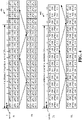
- FIG. 4 is a diagram illustrating non-limiting examples of ULL timelines 400, 402, with time progression extending from left to right in the figure, for managing ULL communications in a wireless communication system.
- timelines 400, 402 include ULL frames of symbol duration in each symbol of a subframe.
- Timelines 400, 402 both depict symbols representing a TTI for ULL physical downlink control channel (uPDCCH) and/or ULL physical downlink shared channel (uPDSCH) and symbols representing a TTI including ULL physical uplink control channel (uPUCCH) and/or ULL physical uplink shared channel (uPUSCH).
- timelines 400 14 symbols are shown within a given subframe (e.g., for normal CP), and in timelines 402, 12 symbols are shown within a given subframe (e.g., for extended CP).
- a TTI may be two or more symbols, a slot of a subframe (where a subframe includes two slots), etc.
- HARQ process response time can be 3 symbols (or 4 symbols, 3 dual-symbols, 3 slots, etc.).
- uPDCCH/uPDSCH is sent in symbol 0, and HARQ is processed and is sent in symbol 4, etc. in the subframe.
- some symbols within a given subframe can be allocated for downlink communications (e.g., uPDCCH/uPDSCH) while other symbols are allocated for uplink communications (e.g., uPUCCH/uPUSCH).
- downlink communications e.g., uPDCCH/uPDSCH
- uplink communications e.g., uPUCCH/uPUSCH
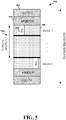
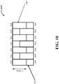
- FIG. 5 is a diagram illustrating a non-limiting example of resource allocations over an available bandwidth 500 (e.g., a system bandwidth) or other allocation space in low latency wireless communications.
- resources are allocated in FDM such that a given portion of frequency (represented vertically) can be allocated to a given UE over a portion of time (represented horizontally), such as one or more TTIs, where the TTIs may be a one-symbol, two-symbol, slot, etc. duration TTIs.
- system bandwidth 500 as depicted, may be defined over a subframe, and ULL transmissions 510 may occur in a symbol, over a two-symbol TTI, etc. or other portion of the subframe.
- PUCCH 502 and uPUCCH 504 regions are shown at the ends of the system bandwidth 500, which can be respectively allocated for PUCCH/uPUCCH communications by one or more UEs.
- the remaining bandwidth 500 may be allocated as a PUSCH and/or uPUSCH 506 region.
- This PUSCH and/or uPUSCH 506 region may include a number of blocks 508, which may each include a number of physical resource blocks (PRB) corresponding to subcarriers in frequency.
- PRB physical resource blocks
- ULL transmissions 510 can be scheduled in one or more blocks 508 of PUSCH and/or uPUSCH 506 region, in one example.
- the PUSCH and uPUSCH 506 regions can be separate from one another (e.g.
- UCI can be transmitted using PUSCH and/or uPUSCH resources (e.g., when the UE has data to transmit, it can be scheduled to also transmit UCI in the uPUSCH resources to maintain the SC-FDM property, but may be scheduled in the PUSCH resources otherwise).
- each downlink channel, such as uPDSCH, received from an access point at a UE can be followed by UL ACK/NAK transmission from the UE.
- the payload size of the UL ACK/NACK can be from 1 bit (one ACK/NAK for one codeword (CW) of one UE scheduled on one component carrier (CC)) to 10 bits (a UE scheduled over 5 CCs with 2 CW per CC), etc. to even larger sizes in case of enhanced carrier aggregation (32 CCs) or TDD (e.g., in DL-heavy frame structures).
- UEs can be requested to provide CQI feedback, which may include 4 bits for full CQI feedback or 2 bits for differential CQI feedback.
- a uPUCCH may be able to handle ACK/NAK feedback for active UEs and also CQI of UEs upon request from an access point.
- different TTI lengths may be envisioned for a uPUCCH, e.g., 2 symbols, 3 symbols, 4 symbols, one slot, etc., given the corresponding low latency technology.
- the uPUCCH TTI length may depend on the payload, UEs' channel conditions and mobility conditions, etc. For example, a cell-edge UE may use a one-slot uPUCCH to achieve uplink performance metrics, while for a cell-center user, a 2-symbol TTI may be sufficient.
- uPDSCH and uPUCCH may have different TTI lengths; for example, while uPDSCH is scheduled over 2-symbol TTIs, uPUCCH could be scheduled over 1-slot TTIs (e.g., to improve uplink coverage).
- ACK/NAK feedback for multiple uPDSCH can be over one uplink TTI.
- CQI of multiple UEs may be fed back over one uplink TTI.
- providing UCI in low latency communication technologies may allow a UE to achieve channel frequency diversity (e.g., through frequency hopping or using a comb structure for resource assignment), to avoid violating the SC-FDM property, to support different UCI payloads and/or channel conditions, to multiplex with other UEs over one UL resource, and/or to reduce DMRS overhead caused by reserving one symbol in the two-symbol TTI for DMRS.
- channel frequency diversity e.g., through frequency hopping or using a comb structure for resource assignment
- FIGs. 6-8 aspects are depicted with reference to one or more components and one or more methods that may perform the actions or functions described herein.
- the term "component” as used herein may be one of the parts that make up a system, may be hardware or software or some combination thereof, and may be divided into other components.
- FIGs. 7-8 are presented in a particular order and/or as being performed by an example component, it should be understood that the ordering of the actions and the components performing the actions may be varied, depending on the implementation.
- FIG. 6 illustrates an example of a system 600 for scheduling ULL communications.
- System 600 includes a UE 602 that communicates with an eNB 604 to access a wireless network, examples of which are described in FIGs. 1-3 (e.g., access points 105, eNB 204, small cell eNB 208, eNB 310, UEs 115, 206, 350, etc.), above.
- a wireless network examples of which are described in FIGs. 1-3 (e.g., access points 105, eNB 204, small cell eNB 208, eNB 310, UEs 115, 206, 350, etc.), above.
- eNB 604 and UE 602 may have established one or more downlink channels over which to communicate via downlink signals 609, which can be transmitted by eNB 604 (e.g., via transceiver 656) and received by UE 602 (e.g., via transceiver 606) for communicating control and/or data messages (e.g., in signaling) from the eNB 604 to the UE 602 over configured communication resources.
- downlink signals 609 can be transmitted by eNB 604 (e.g., via transceiver 656) and received by UE 602 (e.g., via transceiver 606) for communicating control and/or data messages (e.g., in signaling) from the eNB 604 to the UE 602 over configured communication resources.
- eNB 604 and UE 602 may have established one or more uplink channels over which to communicate via uplink signals 608, which can be transmitted by UE 602 (e.g., via transceiver 606) and received by eNB 604 (e.g., via transceiver 656) for communicating control and/or data messages (e.g., in signaling) from the UE 602 to the eNB 604 over configured communication resources.
- uplink signals 608 can be transmitted by UE 602 (e.g., via transceiver 606) and received by eNB 604 (e.g., via transceiver 656) for communicating control and/or data messages (e.g., in signaling) from the UE 602 to the eNB 604 over configured communication resources.
- eNB 604 may communicate a resource assignment 680 (also referred to as a resource grant) that can indicate resources over which the UE 602 is to communicate (e.g., transmit or receive) certain data with eNB 604, where the resources can correspond to a ULL communication technology, as described.
- resources related to a ULL communication technology can relate to a ULL timeline (e.g., a timeline having a TTI that is less than a subframe in duration, such as the timelines 400, 402 in FIG. 4 ), and/or may correspond to an assignment of resources in a system bandwidth (e.g., system bandwidth 500 in FIG. 5 ).
- the resource assignment 680 may correspond to resources for transmitting UCI and/or a related DMRS in one or more symbols of a two-symbol (or more than two-symbol) TTI.
- UE 602 may include one or more processors 603 and/or a memory 605 that may be communicatively coupled, e.g., via one or more buses 607, and may operate in conjunction with or otherwise implement a communicating component 361 for communicating using a ULL communication technologies based on one or more resource assignments to transmit UCI.
- the various operations related to communicating component 361 may be implemented or otherwise executed by one or more processors 603 and, in an aspect, can be executed by a single processor, while in other aspects, different ones of the operations may be executed by a combination of two or more different processors.
- the one or more processors 603 may include any one or any combination of a modem processor, or a baseband processor, or a digital signal processor, or an application specific integrated circuit (ASIC), or a transmit processor, receive processor, or a transceiver processor associated with transceiver 606.
- a modem processor or a baseband processor, or a digital signal processor, or an application specific integrated circuit (ASIC)
- ASIC application specific integrated circuit
- the memory 605 may be a non-transitory computer-readable medium that includes, but is not limited to, random access memory (RAM), read only memory (ROM), programmable ROM (PROM), erasable PROM (EPROM), electrically erasable PROM (EEPROM), a magnetic storage device (e.g., hard disk, floppy disk, magnetic strip), an optical disk (e.g., compact disk (CD), digital versatile disk (DVD)), a smart card, a flash memory device (e.g., card, stick, key drive), a register, a removable disk, and any other suitable medium for storing software and/or computer-readable code or instructions that may be accessed and read by a computer or one or more processors 603.
- memory 605 or computer-readable storage medium may be resident in the one or more processors 603, external to the one or more processors 603, distributed across multiple entities including the one or more processors 603, etc.
- the one or more processors 603 and/or memory 605 may execute actions or operations defined by communicating component 361 or its subcomponents.
- the one or more processors 603 and/or memory 605 may execute actions or operations defined by an assignment receiving component 610 for receiving a resource assignment from one or more eNBs.
- assignment receiving component 610 may include hardware (e.g., one or more processor modules of the one or more processors 603) and/or computer-readable code or instructions stored in memory 605 and executable by at least one of the one or more processors 603 to perform the specially configured resource assigning operations described herein.
- the one or more processors 603 and/or memory 605 may execute actions or operations defined by a UCI indicating component 612 for transmitting over resources assigned by the resource assignment such to indicate UCI (e.g., ACK/NACK feedback. CQI feedback, etc.).
- UCI indicating component 612 may include hardware (e.g., one or more processor modules of the one or more processors 603) and/or computer-readable code or instructions stored in memory 605 and executable by at least one of the one or more processors 603 to perform the specially configured UCI indicating operations described herein.
- eNB 604 may include one or more processors 653 and/or a memory 655 that may be communicatively coupled, e.g., via one or more buses 657, and may operate in conjunction with or otherwise implement a scheduling component 302 for communicating resource assignments for one or more UEs to transmit UCI in ULL wireless communications.
- the various functions related to scheduling component 302 may be implemented or otherwise executed by one or more processors 653 and, in an aspect, can be executed by a single processor, while in other aspects, different ones of the functions may be executed by a combination of two or more different processors, as described above.
- the one or more processors 653 and/or memory 655 may be configured as described in examples above with respect to the one or more processors 603 and/or memory 605 of UE 602.
- the one or more processors 653 and/or memory 655 may execute actions or operations defined by scheduling component 302 or its subcomponents.
- the one or more processors 653 and/or memory 655 may execute actions or operations defined by an assignment generating component 620 for generating a resource assignment for a UE to transmit UCI in one or more symbols of a ULL TTI.
- assignment generating component 620 may include hardware (e.g., one or more processor modules of the one or more processors 653) and/or computer-readable code or instructions stored in memory 655 and executable by at least one of the one or more processors 653 to perform the specially configured assignment generating operations described herein.
- the one or more processors 653 and/or memory 655 may execute actions or operations defined by a UCI processing component 622 for determining UCI transmitted by a UE based at least in part on transmissions over the assigned resources.
- UCI processing component 622 may include hardware (e.g., one or more processor modules of the one or more processors 653) and/or computer-readable code or instructions stored in memory 655 and executable by at least one of the one or more processors 653 to perform the specially configured UCI processing operations described herein.
- transceivers 606, 656 may be configured to transmit and receive wireless signals through one or more antennas 682, 684 and may generate or process the signals using one or more RF front end components (e.g., power amplifiers, low noise amplifiers, filters, analog-to-digital converters, digital-to-analog converters, etc.), one or more transmitters, one or more receivers, etc.
- RF front end components e.g., power amplifiers, low noise amplifiers, filters, analog-to-digital converters, digital-to-analog converters, etc.
- transceivers 606, 656 may be tuned to operate at specified frequencies such that UE 602 and/or eNB 604 can communicate at a certain frequency.
- the one or more processors 603 may configure transceiver 606 and/or one or more processors 653 may configure transceiver 656 to operate at a specified frequency and power level based on a configuration, a communication protocol, etc. to communicate uplink signals 608 and/or downlink signals 609, respectively, over related uplink or downlink communication channels.
- transceivers 606, 656 can operate in multiple bands (e.g., using a multiband-multimode modem, not shown) such to process digital data sent and received using transceivers 606, 656.
- transceivers 606, 656 can be multiband and be configured to support multiple frequency bands for a specific communications protocol.
- transceivers 606, 656 can be configured to support multiple operating networks and communications protocols. Thus, for example, transceivers 606, 656 may enable transmission and/or reception of signals based on a specified modem configuration.
- FIG. 7 illustrates an example of a method 700 for assigning (e.g., by an eNB) resources for transmitting UCI.
- FIG. 8 illustrates an example of a method 800 for transmitting (e.g., by an UE) UCI based on resources assigned by an eNB.
- blocks indicated as dashed boxes represent optional steps.
- the eNB can transmit one or more resource assignments for a UE to transmit over at least one of a first symbol or a second symbol of a first TTI using one or more consecutive frequency resources based on a decimation factor.
- assignment generating component 620 e.g., in conjunction with processor(s) 653, memory 655, and/or transceiver 656, can generate and transmit the one or more resource assignments (e.g., resource assignment 680) for the UE (e.g., UE 602) to transmit over at least one of the first symbol or the second symbol of the first TTI using one or more consecutive frequency resources based on the decimation factor.
- the resource assignment 680 may indicate the one or more consecutive frequency resources for the first symbol and/or for the second symbol in the one or more resource assignments.
- the resource assignment 680 may indicate the one or more consecutive frequency resources for the first symbol based on the decimation factor.
- the decimation factor may allow the eNB 604 to stagger or interleave resource assignments to the UE 602 and other UEs at least in the first symbol for transmitting the reference signal (e.g., DMRS), and also the second symbol in some examples.
- the decimation factor may indicate a division of the consecutive frequency resources, and may be used to determine which of the frequency resources to use for transmission by a UE 602. For example, for at least a portion of the frequency resources, the UE 602 can transmit using every nth resource, where n is the decimation factor, as described further herein.
- assignment generating component 620 may generate a first resource assignment for the UE 602 that includes decimated resources for the first symbol and similarly decimated resources for the second symbol, where the resources for the second symbol may relate to a control channel assignment (e.g., a uPUCCH assignment).
- assignment generating component 620 may generate a first resource assignment for the UE 602 that may or may not include decimated resources for the first symbol and/or the second symbol (e.g., where resources for UE 602 are not interleaved in frequency with resources for other UEs, or may otherwise include substantially all bandwidth (e.g., of a system band)).
- assignment generating component 620 can configure the UE 602 with at least two or more uPUCCH resources, in this regard, where some resources are decimated, or have a comb structure and operation, and some are not decimated, or do not have the comb structure or operating.
- these different uPUCCH resource assignments can correspondingly have different capacity (e.g., due to at least one of the comb structure/operation or lack of comb structure/operation in the second symbol with control data, the number of corresponding resource blocks, etc.) and/or different performance (e.g., due to comb structured DMRS or non-comb structured DMRS based channel estimation in the first symbol).
- assignment generating component 620 may also indicate which resource assignment is assigned to the UE 602, where a corresponding indication may include an information field in downlink control information transmitted to the UE 602 (e.g., in uPDCCH resources assigned to the UE 602).
- the UE can receive one or more resource assignments from an access point to transmit over at least one of a first symbol or a second symbol of a first TTI using one or more consecutive frequency resources, which may be based on a decimation factor.
- assignment receiving component 610 e.g., in conjunction with processor(s) 603, memory 605, and/or transceiver 606, can receive the one or more resource assignments (e.g., resource assignment 680) from the access point (e.g., eNB 604) to transmit over at least one of the first symbol or the second symbol of the first TTI using one or more consecutive frequency resources, which may be based on the decimation factor.
- the one or more resource assignments may indicate the one or more consecutive frequency resources for at least the reference signal transmission over the first symbol, and in some examples may also indicate the one or more consecutive frequency resources (or other consecutive frequency resources), which may be based on a decimation factor for the data signal transmission over the second symbol. In other examples, the frequency resources in at least one of the one or more resource assignments may not be decimated in frequency, as described.
- the UE can select at least one of the one or more resource assignments for transmitting a reference signal and/or a data signal.
- UCI indicating component 612 e.g., in conjunction with processor(s) 603, memory 605, and/or transceiver 606, can select at least one of the one or more resource assignments for transmitting the reference signal and/or the data signal.
- the resource assignments may be based on decimated or non-decimated frequency resources in one or more symbols, and may thus provide different capacities or performances based on frequency resources associated with the respective assignment.
- resource assignments with non-decimated (e.g., non-comb structured) resources may provide additional capacity and/or performance, but may do so at the cost of not allowing other UEs to use the resources.
- UCI indicating component 612 may select a resource assignment with decimated frequency resources (e.g., comb structure) where a payload size for control data is below a threshold size, or may select the resource assignment with non-decimated frequency resources (e.g., non-comb structure) otherwise.
- UCI indicating component 612 may select the resource assignment from the one or more resource assignments based on a RRC configuration received from the eNB 604, an indicated or determined need to multiplex communications with other UEs, etc.
- UCI indicating component 612 may select the resource assignment of the one or more resource assignments to utilize based on an indication from the eNB 604, where the indication can be received in downlink control information received over uPDCCH resources, an a RRC configuration, etc.
- the UE may transmit, in the first TTI, a reference signal over the first symbol and a data signal indicating UCI over the second symbol according to at least one of the one or more resource assignments.
- UCI indicating component 612 e.g., in conjunction with processor(s) 603, memory 605, and/or transceiver 606, can transmit, in the first TTI, a reference signal over the first symbol and a data signal indicating UCI over the second symbol according to the at least one of the one or more resource assignments.
- UCI indicating component 612 can select the at least one of the one or more resource assignments based on one or more considerations or an indication from the eNB 604, as described above, and may transmit the reference signal and/or data signal over the resources in the selected resource assignment.
- the UE may optionally, at Block 806, transmit the reference signal over the one or more consecutive frequency resources, which may be based on the decimation factor, and/or, at Block 808, transmit the data signal over the one or more consecutive frequency resources, which may be based on the decimation factor.
- UCI indicating component 612 e.g., in conjunction with processor(s) 603, memory 605, and/or transceiver 606, can transmit the reference signal (e.g., DMRS) over the one or more consecutive frequency resources, which may be based on the decimation factor (e.g., where the resource assignment corresponds to resources decimated in frequency), and/or can transmit the data signal to indicate UCI over the one or more consecutive frequency resources, which may be based on the decimation factor (e.g., where the resource assignment corresponds to resources decimated in frequency), as described further herein.
- the reference signal e.g., DMRS
- the decimation factor e.g., where the resource assignment corresponds to resources decimated in frequency
- the eNB can receive, in the first TTI, a reference signal over the first symbol and a data signal indicating UCI over the second symbol according to at least one of the one or more resource assignments.
- UCI processing component 622 e.g., in conjunction with processor(s) 653, memory 655, and/or transceiver 656, can receive, in the first TTI, the reference signal over the first symbol and the data signal indicating UCI over the second symbol according to at least one of the one or more resource assignments.
- UCI processing component 622 can receive at least the reference signal (e.g., DMRS) over the one or more consecutive frequency resources, which may be based on the decimation factor (e.g., where the resource assignment corresponds to resources decimated in frequency), and/or also the data signal over one or more consecutive frequency resources, which may be based on a decimation factor in the second symbol (e.g., where resource assignment corresponds to resources decimated in frequency), in some examples.
- the reference signal e.g., DMRS
- the decimation factor e.g., where the resource assignment corresponds to resources decimated in frequency
- the data signal e.g., where resource assignment corresponds to resources decimated in frequency
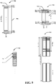
- allocation space 900 may include all or a portion of a system bandwidth over two symbols 902, 904.
- symbol 902 may include a resources 906 assigned to one UE (e.g., UE 602), resources 908 assigned to another UE, and other resources assigned to other UEs in a comb structure, where each resource in resources 906 and 908 and the other individual resources (e.g., subcarriers, tones, etc.) can be referred to as comb teeth.
- Each of resources 906 and resources 908 include consecutive frequency resources in the symbol 902 according to a decimation factor (e.g., a factor of 4, or every 4th frequency resource or comb tooth, as shown), where the resources 906 and 908 are offset from one another to provide orthogonality.
- the resources 906 and/or 908 may span the entire allocation space 900 and/or system bandwidth and/or one or more other blocks or portions thereof.
- assignment receiving 610 can receive a resource assignment 680 indicating resources 906 and/or a related comb index (e.g., an offset of one or more resources in the symbol 902), a decimation factor, etc., and can transmit DMRS over the first symbol 902 at one or more of the consecutive frequency resources 906 assigned to the UE based on the comb index, decimation factor, etc. This allows the UEs to transmit orthogonal DMRS, as described herein.
- a resource assignment 680 indicating resources 906 and/or a related comb index (e.g., an offset of one or more resources in the symbol 902), a decimation factor, etc.
- assignment generating component 620 may assign a physical resource block (PRB) (e.g., 12 consecutive subcarriers) to the UE 602 (e.g., and/or additional PRBs to other UEs) for transmitting UCI in the symbol 904 in the resource assignment 680.
- PRB physical resource block
- assignment receiving component 610 can receive the resource assignment 680 and accordingly transmit UCI over the PRB in symbol 904.
- assignment generating component 620 may assign substantially all PRBs in a system bandwidth to the UE 602 for transmitting UCI in the symbol 904.
- assignment generating component 620 may assign symbol 904 to UE 602 where there is only one UE scheduled to transmit UCI in the symbol, based on a payload size of the UCI achieving a threshold (e.g., in enhanced carrier aggregation where the UE 602 reports UCI for multiple component carriers), etc.
- UCI indicating component 612 can transmit the UCI us SC-FDM over the frequency resources of the symbol 904.
- assignment generating component 620 may assign, in the resource assignment 680, cyclic shifts to the UE 602 to be used in transmitting over one or more PRBs of the symbol 904, as described further herein.
- assignment receiving component 610 can receive the cyclic shifts, and UCI indicating component 612 may select a cyclic shift for transmitting UCI in symbol 904, where the cyclic shift may indicate UCI when considered with a number of cyclic shift options for the UE 602 (e.g., and/or where the cyclic shift(s) may be assigned to the UE 602 in the resource assignment generated by assignment generating component 620).
- the selection of 1 out of k CSs in each group can convey log_2(k) bits for each UE.
- the selected CS can be used to modulate the data symbol 904 to indicate the bits for UCI. For example, with QPSK modulation, 2 + log_2(k) bits can be transmitted to each UE.
- the eNB may optionally assign a set of cyclic shifts to use in indicating the UCI in transmitting at least the second symbol.
- assignment generating component 620 e.g., in conjunction with processor(s) 653, memory 655, and/or transceiver 656, can assign, to the UE 602, the set of cyclic shifts to use in indicating the UCI in transmitting at least the second symbol.
- assignment generating component 620 may indicate the cyclic shifts as part of the resource assignment 680 or a separate communication/configuration for the UE 602.
- assignment generating component 620 may assign different cyclic shifts to different UEs to allow the UEs to multiplex UCI in the second symbol.
- the UE can optionally determine a cyclic shift for applying to at least the second symbol to communicate UCI.
- UCI indicating component 612 e.g., in conjunction with processor(s) 603, memory 605, and/or transceiver 606, can determine the cyclic shift for applying to at least the second symbol to communicate the UCI.
- assignment receiving component 610 can receive a set of cyclic shifts assigned to the UE 602 (e.g., from eNB 604 and/or a received configuration).
- UCI indicating component 612 can select a cyclic shift to indicate the UCI (e.g., up to log_2(k) bits for k possible cyclic shifts in the set). Accordingly, for example, UCI indicating component 612 can transmit the data signal over the second symbol (e.g., at Block 804) based on applying the cyclic shift such to indicate the UCI. Similarly, in this example, the UCI processing component 622 can receive the data signal (e.g., at Block 704) and determine the cyclic shift, such to process the bits of the UCI.
- the eNB may optionally, at Block 708, determine the UCI based at least in part on determining a cyclic shift of the data signal over the second symbol.
- UCI processing component 622 e.g., in conjunction with processor(s) 653, memory 655, and/or transceiver 656, can determine the UCI based at least in part on determining a cyclic shift of the data signal over the second symbol.
- UCI processing component 622 can determine the set of cyclic shifts provided to the UE 602 and bits or UCI values associated with each of the cyclic shifts, and can accordingly determine the UCI based on the cyclic shift.
- UCI indicating component 612 may indicate 2 bits (e.g., one or more ACK/NACKs, a differential CQI, etc.), and UCI processing component 622 can accordingly process the two bits to determine the UCI.
- UCI indicating component 612 may also transmit the reference signal in the first symbol (e.g., symbol 902) using one or more remaining cyclic shifts not assigned to any UE by the eNB 604 and/or using one or more computer generated sequences (CGS) determined to have low (or lowest) peak-to-average power ratio (PAPR).
- assignment generating component 620 may indicate any remaining cyclic shifts and/or CGSs to the UE 602 (e.g., in the resource assignment 680, in other dedicated signaling, such as RRC signaling, etc.), and UCI indicating component 612 can accordingly determine and apply one of the cyclic shifts and/or CGSs to the reference signal for transmitting the first symbol.
- assignment receiving 610 receives a resource assignment 680 or other configuration indicating a comb index and/or a number, k, of subcarriers
- UCI indicating component 612 transmits over the k subcarriers based on the comb index
- a determined optimal sequence of QPSK symbols of length k can be obtained to minimize the PAPR over possible sequences of length k.
- the optimal sequences and corresponding values of k and/or comb index can be configured in the UE 602 or otherwise received in a configuration from eNB 604 or other network components.
- Allocation space 910 may include a portion of a system bandwidth over two symbols 912, 914.
- symbol 912 may include resource 916 for assigning to one UE (e.g., UE 602) and resources 918 for assigning to another UE.
- Each of resources 916 and resources 918 can include consecutive frequency resources in both of the symbols 912 and 914 according to a decimation factor (e.g., a factor of 4, or every 4th frequency resource or comb tooth, as shown), where the resources 916 and 918 are offset from one another to provide orthogonality.
- a decimation factor e.g., a factor of 4, or every 4th frequency resource or comb tooth, as shown
- the resources 916 and/or 918 may span the entire allocation space 910 and/or system bandwidth and/or one or more other blocks or portions thereof.
- assignment receiving component 610 can receive a resource assignment 680 indicating resources 916 over symbols 912 and 914, and can transmit DMRS over the first symbol 912 at one or more of the consecutive frequency resources 906 assigned to the UE over the first symbol 912, and transmit UCI over the second symbol 914 at one or more of the consecutive frequency resources 906 assigned to the UE over the second symbol 914. This allows the UEs to transmit orthogonal DMRS and UCI, as described herein.
- Allocation space 920 shows an example where both symbols (or one symbol in a one symbol TTI, and/or multiple symbols in a multiple symbol TTI) include resources allocated according to a decimation factor, though not all resources need be allocated (e.g., 3 resources are allocated to UE 2).
- allocation space 930 shows an example similar to allocation space 910 where resources are assigned over one block (or partially over one block) of multiple blocks in the system bandwidth.
- decimation factors among symbols 912 and 914 can be different, and the resources in a given symbol 912 or 914 can be assigned to different UEs or sets of UEs.
- symbol 912 may include resources assigned to allow 2 different UEs to transmit DRMS
- symbol 914 may include resources assigned to allow 4 different UEs (which may or may not include the 2 UEs transmitting DMRS) to transmit control data.
- UCI indicating component 612 can transmit the DMRS in the first symbol 912 using a cyclic shift or CGS and other UEs can transmit DMRS in the first symbol 912 using different cyclic shifts or CGS to provide orthogonality.
- assignment generating component 620 may assign the cyclic shifts and/or CGSs to the UEs (e.g., UE 602) for DMRS transmission in the first symbol 912.
- assignment generating component 620 may semi-statically assign the resources 916, 918, etc.
- assignment generating component 620 may assign the resources 916 to UE 602 in the resource assignment 680 as part of a downlink grant.
- assignment receiving component 610 may receive an indication of the resources 916 in the downlink resource grant, and may utilize the resources 916 to transmit DMRS and/or UCI on the appropriate symbol 912 or 914.
- assignment receiving component 610 may determine the resources 916 implicitly (e.g., based on a control channel element (CCE) assigned by the eNB 604 via assignment generating component 620, semi-statically, such as based on an identifier of the UE 602, etc.).
- CCE control channel element
- the eNB may also transmit other resource assignments to other UEs (e.g., to assign resources 908, 918 and/or other resources).
- assignment generating component 620 may generate resource assignments for various UEs that can vary in size (e.g., depending on a payload of the UCI for the UE).
- the eNB at Block 710, determines the decimation factor based at least in part on a UCI payload of the UE.
- assignment generating component 620 e.g., in conjunction with processor(s) 653, memory 655, and/or transceiver 656, can determine the decimation factor based at least in part on the UCI payload of the UE.
- the UE 602 may indicate an expected UCI payload and/or the eNB 604 may otherwise receive, determine, or predict the UCI payload, or otherwise determine to assign more resources to the UE 602 than to another UE.
- assignment generating component 620 can select a smaller decimation factor for a UE 602 to allow increased payload for UCI transmissions.
- assignment generating component 620 can select a larger decimation factor to support additional UEs, to support additional CWs per UE, etc.
- assignment generating component 620 may determine to assign resources to UEs using a tree based interlace allocation scheme. For example, assignment generating component 620 may divide the resources into various levels with associated decimation factors. For example, the resources may be divided into two levels of a similar number of resources at decimation level two. One or more of the two levels can be divided into two levels of a similar number of resources at a decimation level four, and so on.
- assignment generating component 620 may assign a UE a decimation level 2 (e.g., every other frequency resource) and assign two other UEs decimation level 4 (e.g., every fourth frequency resource) such that the resources are assigned as follows: UE1 UE2 UE1 UE3 UE1 UE2 UE1 UE3 ... where UE1 is assigned resources based on a decimation level 2, and UE2 and UE3 are assigned resources based on a decimation level 4 (which are comprised of the remaining decimation level 2 resources not assigned to UE1).
- assignment generating component 620 can further divide each level into additional levels (e.g., decimation level 8, 16, etc.) to allocate resources to additional UEs, etc.
- assignment generating component 620 may assign at least a portion of the unused frequency resources in the DMRS and/or data symbol to one or more UEs to allow transmission of additional data.
- the UE may transmit the UCI in the second symbol as one or more of ACK/NACK feedback, CQI feedback, and/or data (e.g., ACK/NACK only, CQI only, ACK/NACK + CQI, ACK/NACK + Data, CQI + Data, or ACK/NACK + CQI + Data).
- UCI indicating component 612 transmits ACK/NACK feedback
- it may utilize uPUCCH resources.
- UCI indicating component 612 transmits CQI and/or ACK/NACK + CQI
- it may utilize the fraction of uPUSCH resources as described above to transmit the UCI in the second symbol in an IFDMA fashion.
- assignment generating component 620 can indicate in the downlink resource grant whether the UE 602 is to transmit CQI (e.g., whether the sub-block is present in the uPUSCH).
- uPUSCH can be transmitted in one or more blocks in a lower part of the system bandwidth (e.g., as in allocation space 930 of FIG. 9 ).
- UCI indicating component 612 transmits UCI + Data, it may multiplex the UCI and data over uPUSCH resources.
- each first symbol of each TTI for DMRS transmission may introduce significant overhead (e.g., 50%) for transmitting DMRS.
- the DMRS may be shared across multiple consecutive TTIs, in one example.
- DMRSs of different UEs scheduled over multiple TTIs can be distinguished via using different cyclic shifts and/or resources (e.g., comb teeth).
- a pattern for transmitting reference symbols and data can be configured. For example, consecutive symbols in a slot can be data (D), reference signal (R), D, D, D, R, D.
- possible patterns may include (D, D), (R, D), (D, R), and (R, D, D) for the symbols, and assignment generating component 620 may signal to the UE 602 which pattern to use.
- the pattern is based on a downlink TTI location.
- a default UL pattern for two-symbol TTI can be defined.
- the eNB transmits another resource assignment for the UE to transmit data signals over a plurality of symbols in a second TTI.
- assignment generating component 620 e.g., in conjunction with processor(s) 653, memory 655, and/or transceiver 656, can transmit another resource assignment for the UE 602 to transmit data signals over the plurality of symbols in the second TTI.
- assignment generating component 620 assigns resources for (R, D) in the first TTI, and (D, D) in the second TTI. This allows the UE to transmit additional UCI and/or data in the second TTI without having to also transmit DMRS over either of the symbols.
- the UE 602 can receive the resource assignment and may optionally, at Block 812, transmit, in a second TTI, one or more data signals indicating UCI and/or data in a plurality of the symbols based on the reference signal.
- UCI indicating component 612 e.g., in conjunction with processor(s) 603, memory 605, and/or transceiver 606, can transmit, in the second TTI, one or more data signals indicating UCI and/or data in the plurality of the symbols based on the reference signal.
- the reference signal is the reference signal transmitted in the first TTI.
- the eNB may optionally, at Block 714, demodulate the data signals (e.g., as received in the second TTI) based on a channel estimate determined from the reference signal in the first symbol of the first TTI.
- UCI processing component 622 e.g., in conjunction with processor(s) 653, memory 655, and/or transceiver 656, can demodulate the data signals (e.g., as received in the second TTI) based on a channel estimate determined from the reference signal in the first symbol of the first TTI. This facilitates utilizing the reference signal for multiple TTIs, which lowers the DMRS overhead, as described.
- assignment generating component 620 can extend TTIs over which reference signals and data signals are transmitted to include twice as many resources as TTIs over which only data signals are transmitted. This is shown in FIG. 10 , which illustrates an example bandwidth 1000 with 2 PRBs allocated for each TTI having a reference signal, and one PRB for each TTI having only data symbols. This can facilitate the same or similar payload for a UE (UE1) transmitting UCI in each TTI.
- assignment generating component 620 can assign another UE (UE2) resources based on the PRB allocations for UE1, where the UE2 can be assigned to transmit only data symbols in a TTI where UE1 is assigned to transmit reference and data symbols, and vice versa.
- assignment generating component 620 can indicate the PRB assignment to the UEs in the downlink resource grant, as described. Moreover, in an example, assignment generating component 620 can assign resources for a (D, R) or (R, D) TTI for transmitting either ACK/NACK or CQI, and can assign resources for a (D, D) TTI for transmitting both ACK/NACK and CQI.
- UCI can be multiplexed and/or joint/separately coded.
- the UE may optionally, at Block 814, multiplex ACK/NACK feedback and CQI feedback and spread the multiplexed feedback over the plurality of symbols in the second TTI.
- UCI indicating component 612 e.g., in conjunction with processor(s) 603, memory 605, and/or transceiver 606, can multiplex ACK/NACK feedback and CQI feedback and spread (e.g., DFT spread) the multiplexed feedback over the plurality of symbols in the second TTI.
- the UE in transmitting in the second TTI, may optionally, at Block 816, perform separate coding of the plurality of symbols in the second TTI.
- UCI indicating component 612 e.g., in conjunction with processor(s) 603, memory 605, and/or transceiver 606, can perform separate coding of the plurality of symbols in the second TTI.
- UCI indicating component 612 can perform separate coding of ACK/NACK feedback and CQI feedback to produce two sets of coded symbols, which may be transmitted in one or more data symbols (e.g., using different resource elements in one or more data symbols - such as in a data symbol in a (R, D) or (D, R) TTI, using different data symbols - such as in a (D, D) TTI, etc.).
- UCI indicating component 612 may optionally puncture resources, rate match around resources, etc. in transmitting over the second TTI.
- the UE may optionally, at Block 818, perform joint coding of the UCI over available uplink resources in a TTI.
- UCI indicating component 612 e.g., in conjunction with processor(s) 603, memory 605, and/or transceiver 606, can perform joint coding of the UCI (e.g., ACK/NACK feedback and CQI feedback) over available uplink resources of substantially any TTI (e.g., resources in both symbols of a two-symbol TTI).
Description
- Described herein are aspects generally related to communication systems, and more particularly, to communicating feedback in low latency communication systems.
- Wireless communication systems are widely deployed to provide various telecommunication services such as telephony, video, data, messaging, and broadcasts. Typical wireless communication systems may employ multiple-access technologies capable of supporting communication with multiple users by sharing available system resources (e.g., bandwidth, transmit power). Examples of such multiple-access technologies include code division multiple access (CDMA) systems, time division multiple access (TDMA) systems, frequency division multiple access (FDMA) systems, orthogonal frequency division multiple access (OFDMA) systems, single-carrier frequency division multiple access (SC-FDMA) systems, and time division synchronous code division multiple access (TD-SCDMA) systems.
- These multiple access technologies have been adopted in various telecommunication standards to provide a common protocol that enables different wireless devices to communicate on a municipal, national, regional, and even global level. An example of a telecommunication standard is Long Term Evolution (LTE). LTE is a set of enhancements to the Universal Mobile Telecommunications System (UMTS) mobile standard promulgated by Third Generation Partnership Project (3GPP). It is designed to better support mobile broadband Internet access by improving spectral efficiency, lower costs, improve services, make use of new spectrum, and better integrate with other open standards using OFDMA on the downlink (DL), SC-FDMA on the uplink (UL), and multiple-input multiple-output (MIMO) antenna technology. However, as the demand for mobile broadband access continues to increase, further improvements in LTE technology may be desired. Preferably, these improvements should be applicable to other multi-access technologies and the telecommunication standards that employ these technologies.
- In wireless communication systems employing legacy LTE, a plurality of UEs served by a particular eNodeB may be scheduled resources for communicating with the eNodeB over one or more channels using transmission time intervals (TTI) on the order of a 1 millisecond subframe. As UE capabilities and demand for bandwidth increases, lower latency in communications may be desired.
- LG Electronics: "Discussion on PUCCH design for HARQ-ARK in shortened TTI", R1-163520 relates to PUCCH formats for shortened TTI for UL transmission. 3GPP TS 36.211 version 12.1.0
Release 13, chapter 5.4 relates to PUCCH formats and resources. ZTE: "PUCCH design for shortened TTI", R1-162403 relates to design of 2-symbol PUCCH for short TTI. Qualcomm Incorporated, R1-163069 relates to uplink design details for TTI shortening and reduced processing time. NTT Docomo, Inc., R1-160965 relates to PUSCH and PUCCH in short-TTI.EP2942896 relates to efficiently transmitting/receiving uplink signals in a carrier aggregation based wireless communication system.WO2016/048595 relates to determining whether to transmit a demodulation reference signal for an uplink control channel in at least one TTI based on an indicator received from a network entity. - The following presents a simplified summary of one or more aspects in order to provide a basic understanding of such aspects. This summary is not an extensive overview of all contemplated aspects, and is intended to neither identify key or critical elements of all aspects nor delineate the scope of any or all aspects. Its sole purpose is to present some concepts of one or more aspects in a simplified form as a prelude to the more detailed description that is presented later. The invention is defined by the appended
independent claims - According to an example, a method for communicating uplink control information (UCI) in low-latency communications is provided. The method includes receiving a resource assignment from an access point to transmit over a first symbol and a second symbol that comprise a first TTI, wherein the resource assignment includes, at least for the first symbol, an indication of one or more consecutive frequency resources in a system bandwidth based on a decimation factor, and transmitting, in the first TTI, a reference signal over the first symbol and a data signal indicating UCI over the second symbol according to the resource assignment.
- In other aspects, a method for communicating uplink control information (UCI) in low-latency communications is provided. The method includes transmitting a resource assignment for a user equipment to transmit over a first symbol and a second symbol that comprise a first TTI, wherein the resource assignment includes, at least for the first symbol, an indication of one or more consecutive frequency resources in a system bandwidth based on a decimation factor, and receiving, in the first TTI, a reference signal over the first symbol and a data signal indicating UCI over the second symbol according to the resource assignment.
- In a further aspect, an apparatus for wireless communications is provided. The apparatus includes a transceiver for communicating one or more wireless signals via one or more antennas, a memory configured to store instructions, and one or more processors communicatively coupled with the transceiver and the memory. The one or more processors are configured to receive one or more resource assignments from an access point to transmit over a first symbol and a second symbol that comprise a first TTI, wherein a resource assignment of the one or more resource assignments includes, at least for the first symbol, an indication of one or more consecutive frequency resources in a system bandwidth based on a decimation factor, and transmit, in the first TTI, a reference signal over the first symbol and a data signal indicating UCI over the second symbol according to the one or more resource assignments.
- In another aspect, an apparatus for wireless communications is provided including a transceiver for communicating one or more wireless signals via one or more antennas, a memory configured to store instructions, and one or more processors communicatively coupled with the transceiver and the memory. The one or more processors are configured to transmit one or more resource assignments for a user equipment to transmit over a first symbol and a second symbol that comprise a first TTI, wherein at least one resource assignment of the one or more resource assignments includes, at least for the first symbol, an indication of one or more consecutive frequency resources in a system bandwidth based on a decimation factor, and receive, in the first TTI, a reference signal over the first symbol and a data signal indicating UCI over the second symbol according to the one or more resource assignments.
- In a further aspect, an apparatus for wireless communications is provided. The apparatus includes means for receiving one or more resource assignments from an access point to transmit over a first symbol and a second symbol that comprise a first TTI, wherein a resource assignment of the one or more resource assignments includes, at least for the first symbol, an indication of one or more consecutive frequency resources in a system bandwidth based on a decimation factor, and means for transmitting, in the first TTI, a reference signal over the first symbol and a data signal indicating UCI over the second symbol according to the one or more resource assignments.
- In another aspect, an apparatus for wireless communications is provided including means for transmitting one or more resource assignments for a user equipment to transmit over a first symbol and a second symbol that comprise a first TTI, wherein at least one resource assignment of the one or more resource assignments includes, at least for the first symbol, an indication of one or more consecutive frequency resources in a system bandwidth based on a decimation factor, and means for receiving, in the first TTI, a reference signal over the first symbol and a data signal indicating UCI over the second symbol according to the one or more resource assignments.
- In a further aspect, a computer-readable medium including computer executable code for wireless communications is provided. The code includes code for receiving one or more resource assignments from an access point to transmit over a first symbol and a second symbol that comprise a first TTI, wherein a resource assignment of the one or more resource assignments includes, at least for the first symbol, an indication of one or more consecutive frequency resources in a system bandwidth based on a decimation factor, and code for transmitting, in the first TTI, a reference signal over the first symbol and a data signal indicating UCI over the second symbol according to the one or more resource assignments.
- In another aspect, a computer-readable medium including computer executable code for wireless communications is provided. The code includes code for transmitting one or more resource assignments for a user equipment to transmit over a first symbol and a second symbol that comprise a first TTI, wherein at least one resource assignment of the one or more resource assignments includes, at least for the first symbol, an indication of one or more consecutive frequency resources in a system bandwidth based on a decimation factor, and code for receiving, in the first TTI, a reference signal over the first symbol and a data signal indicating UCI over the second symbol according to the one or more resource assignments.
- To the accomplishment of the foregoing and related ends, the one or more aspects comprise the features hereinafter fully described and particularly pointed out in the claims. The following description and the annexed drawings set forth in detail certain illustrative features of the one or more aspects. These features are indicative, however, of but a few of the various ways in which the principles of various aspects may be employed, and this description is intended to include all such aspects and their equivalents.
- In order to facilitate a fuller understanding of aspects described herein, reference is now made to the accompanying drawings, in which like elements are referenced with like numerals. These drawings should not be construed as limiting the present disclosure, but are intended to be illustrative only.
-
FIG. 1 shows a block diagram conceptually illustrating an example of a telecommunications system, in accordance with aspects described herein. -
FIG. 2 is a diagram illustrating an example of an access network. -
FIG. 3 is a diagram illustrating an example of an evolved Node B and user equipment in an access network. -
FIG. 4 is a diagram illustrating examples of timelines for ultra low latency (ULL) bandwidth allocation. -
FIG. 5 is a diagram illustrating an example of a system bandwidth in accordance with aspects described herein. -
FIG. 6 is a diagram illustrating an example of a system for communicating in a ULL wireless communication technology in accordance with aspects described herein. -
FIG. 7 is a flow chart of an example of a method for receiving ULL wireless communications in accordance with aspects described herein. -
FIG. 8 is a flow chart of an example of a method for transmitting ULL wireless communications in accordance with aspects described herein. -
FIG. 9 illustrates diagrams of examples of allocation spaces for allocating resources in ULL communications in accordance with aspects described herein. -
FIG. 10 illustrates a diagram of an example of an allocation space for data and reference signals in ULL communications in accordance with aspects described herein. - The detailed description set forth below in connection with the appended drawings is intended as a description of various configurations and is not intended to represent the only configurations in which the concepts described herein may be practiced. The detailed description includes specific details for the purpose of providing a thorough understanding of various concepts. However, it will be apparent to those skilled in the art that these concepts may be practiced without these specific details. In some instances, well known structures and components are shown in block diagram form in order to avoid obscuring such concepts.
- Several aspects of telecommunication systems will now be presented with reference to various apparatus and methods. These apparatus and methods will be described in the following detailed description and illustrated in the accompanying drawings by various blocks, modules, components, circuits, steps, processes, algorithms, etc. (collectively referred to as "elements"). These elements may be implemented using electronic hardware, computer software, or any combination thereof. Whether such elements are implemented as hardware or software depends upon the particular application and design constraints imposed on the overall system.
- By way of example, an element, or any portion of an element, or any combination of elements may be implemented with a "processing system" that includes one or more processors. Examples of processors include microprocessors, microcontrollers, digital signal processors (DSPs), field programmable gate arrays (FPGAs), programmable logic devices (PLDs), state machines, gated logic, discrete hardware circuits, and other suitable hardware configured to perform the various functionality described throughout this disclosure. One or more processors in the processing system may execute software. Software shall be construed broadly to mean instructions, instruction sets, code, code segments, program code, programs, subprograms, software modules, applications, software applications, software packages, routines, subroutines, objects, executables, threads of execution, procedures, functions, etc., whether referred to as software, firmware, middleware, microcode, hardware description language, or otherwise.
- Accordingly, in one or more aspects, the functions described may be implemented in hardware, software, firmware, or any combination thereof. If implemented in software, the functions may be stored on or encoded as one or more instructions or code on a computer-readable medium. Computer-readable media includes computer storage media. Storage media may be any available media that can be accessed by a computer. By way of example, and not limitation, such computer-readable media can comprise RAM, ROM, EEPROM, CD-ROM or other optical disk storage, magnetic disk storage or other magnetic storage devices, or any other medium that can be used to carry or store desired program code in the form of instructions or data structures and that can be accessed by a computer. Disk and disc, as used herein, includes compact disc (CD), laser disc, optical disc, digital versatile disc (DVD), and floppy disk where disks usually reproduce data magnetically, while discs reproduce data optically with lasers. Combinations of the above should also be included within the scope of computer-readable media.
- Described herein are various aspects related to communicating feedback in a low latency communication technology (e.g., ultra-low latency (ULL) LTE). For example, a low latency communication technology may be based on a legacy wireless communication technology, such as third generation partnership project (3GPP) long term evolution (LTE), but may utilize different length transmission time intervals (TTI) (e.g., the low latency communication technology may have a shorter TTI duration than the legacy communication technology). For example, a legacy LTE technology may utilize a TTI having a duration of a subframe defined in LTE (e.g., 1 millisecond), where ULL LTE technology can be based on a TTI having a duration less than a subframe. In an example, the TTI and associated duration of ULL LTE can be based on defined portions of a subframe, such as one symbol, two symbols, a subframe slot, etc., where a subframe can have 12-14 symbols, two slots, etc. In this regard, a lower latency in communications is achieved by the shorter, more frequent TTI.
- In a low latency communication technology using a two-symbol TTI, a demodulation reference signal (DMRS) and control data (e.g., uplink control information (UCI)) may be transmitted in each symbol using frequency hopping to provide frequency diversity. In some configurations, however, one of the two symbols may be reserved for DMRS transmissions and the other for data transmissions. In such configurations, frequency hopping across multiple symbols may not be usable. For example, the symbol used for data transmission may use a cyclic shift selected to indicate UCI. In another example, resources over the symbol used for data transmission may be assigned to one or more UEs based on a decimation factor to provide the UEs with multiple bits to transmit UCI. In an example, the resources may be assigned based on UCI payload for a given UE (e.g., whether the UE is to transmit acknowledgement (ACK)/negative-ACK (NACK) feedback, channel quality indicator (CQI) feedback, and/or the like). Moreover, in an example, the symbol reserved for DMRS transmission may be similarly divided for assigning frequency resources (e.g., subcarriers, tones, etc.) to the UEs based on the same or a different decimation factor to maintain orthogonality of the DMRS transmissions.
- In addition, for example, in some TTIs, both symbols may be assigned for transmitting data, and may depend on a reference signal in a previous TTI for channel estimation/demodulation of the data. This can reduce DMRS overhead otherwise caused by allocating one of the two symbols for DMRS transmission in each TTI. Additionally, TTIs having two assigned data symbols may be used to transmit more UCI (e.g., ACK/NACK and CQI as opposed to one or the other) as opposed to a TTI having one or two symbols assigned for reference signals and/or control data. Moreover, though the concepts described above and herein are generally shown as corresponding to a two-symbol TTI, similar concepts may be applied to TTIs having two or more symbols where at least one symbol in at least one TTI is assigned for reference signal transmission.
- Referring first to
FIG. 1 , a diagram illustrates an example of awireless communications system 100, in accordance with aspects described herein. Thewireless communications system 100 includes a plurality of access points (e.g., base stations, eNBs, or WLAN access points) 105, a number of user equipment (UEs) 115, and acore network 130. Access points 105 may include ascheduling component 302 configured to allocate resources for communicating withUEs 115 using a ULL communication technology to receive UCI transmissions therefrom. Similarly, one or more ofUEs 115 may include a communicatingcomponent 361 configured to communicate with one ormore access points 105 using the ULL communication technology (e.g., ULL LTE) to transmit UCI. Some of theaccess points 105 may communicate with theUEs 115 under the control of a base station controller (not shown), which may be part of thecore network 130 or the certain access points 105 (e.g., base stations or eNBs) in various examples. Access points 105 may communicate control information and/or user data with thecore network 130 throughbackhaul links 132. In examples, theaccess points 105 may communicate, either directly or indirectly, with each other overbackhaul links 134, which may be wired or wireless communication links. Thewireless communications system 100 may support operation on multiple carriers (waveform signals of different frequencies). Multi-carrier transmitters can transmit modulated signals simultaneously on the multiple carriers. For example, eachcommunication link 125 may be a multi-carrier signal modulated according to the various radio technologies described above. Each modulated signal may be sent on a different carrier and may carry control information (e.g., reference signals, control channels, etc.), overhead information, data, etc. - In some examples, at least a portion of the
wireless communications system 100 may be configured to operate on multiple hierarchical layers in which one or more of theUEs 115 and one or more of theaccess points 105 may be configured to support transmissions on a hierarchical layer that has a reduced latency with respect to another hierarchical layer. In some examples, aUE 115 may communicate withaccess point 105 on one or more of a first hierarchical layer that supports first layer transmissions using a first TTI (which may relate to a "legacy communication technology") and a second hierarchical layer that supports second layer transmissions using a second TTI, which may be shorter than the first TTI (which may relate to a "ULL communication technology"). - In other examples, a
UE 115 may communicate with anaccess point 105 on the second hierarchical layer only. Thus, aUE 115 may belong to a second class ofUEs 115 that may communicate on the second hierarchical layer, while anotherUE 115 may belong to a first class ofUEs 115 that may communicate on the first hierarchical layer only. In an example,access point 105 andUE 115 may communicate on the second hierarchical layer through transmissions of subframes of a second subframe type.Access point 105 may transmit communications related to the first or second hierarchical layer only or may transmit communications for both the first and second hierarchical layers. Where anaccess point 105 supports both the first and second hierarchical layers, communicatingcomponent 361 can be configured to prioritize communications received from theaccess point 105 that relate to the first and second hierarchical layers, as described herein. - The access points 105 may wirelessly communicate with the
UEs 115 via one or more access point antennas. Each of theaccess points 105 sites may provide communication coverage for arespective coverage area 110. In some examples,access points 105 may be referred to as a base transceiver station, a radio base station, a radio transceiver, a basic service set (BSS), an extended service set (ESS), a NodeB, eNodeB, Home NodeB, a Home eNodeB, or some other suitable terminology. Thecoverage area 110 for a base station may be divided into sectors making up only a portion of the coverage area (not shown). Thewireless communications system 100 may includeaccess points 105 of different types (e.g., macro, micro, and/or pico base stations). The access points 105 may also utilize different radio technologies, such as cellular and/or WLAN radio access technologies (RAT). The access points 105 may be associated with the same or different access networks or operator deployments. The coverage areas ofdifferent access points 105, including the coverage areas of the same or different types ofaccess points 105, utilizing the same or different radio technologies, and/or belonging to the same or different access networks, may overlap. - In network communication systems using LTE/LTE-A and/or ULL LTE communication technologies, the terms evolved Node B (eNodeB or eNB) may be generally used to describe the access points 105. The
wireless communications system 100 may be a Heterogeneous LTE/LTE-A/ULL LTE network in which different types of access points provide coverage for various geographical regions. For example, eachaccess point 105 may provide communication coverage for a macro cell, a pico cell, a femto cell, and/or other types of cell. Small cells such as pico cells, femto cells, and/or other types of cells may include low power nodes or LPNs. A macro cell generally covers a relatively large geographic area (e.g., several kilometers in radius) and may allow unrestricted access byUEs 115 with service subscriptions with the network provider. A small cell would generally cover a relatively smaller geographic area and may allow unrestricted access byUEs 115 with service subscriptions with the network provider, for example, and in addition to unrestricted access, may also provide restricted access byUEs 115 having an association with the small cell (e.g., UEs in a closed subscriber group (CSG), UEs for users in the home, and the like). An eNB for a macro cell may be referred to as a macro eNB. An eNB for a small cell may be referred to as a small cell eNB. An eNB may support one or multiple (e.g., two, three, four, and the like) cells. - The
core network 130 may communicate with the eNBs orother access points 105 via one or more backhaul links 132 (e.g., S1 interface, etc.). The access points 105 may also communicate with one another, e.g., directly or indirectly via backhaul links 134 (e.g., X2 interface, etc.) and/or via backhaul links 132 (e.g., through core network 130). Thewireless communications system 100 may support synchronous or asynchronous operation. For synchronous operation, theaccess points 105 may have similar frame timing, and transmissions fromdifferent access points 105 may be approximately aligned in time. For asynchronous operation, theaccess points 105 may have different frame timing, and transmissions fromdifferent access points 105 may not be aligned in time. Furthermore, transmissions in the first hierarchical layer and second hierarchical layer may or may not be synchronized among access points 105. The techniques described herein may be used for either synchronous or asynchronous operations. - The
UEs 115 are dispersed throughout thewireless communications system 100, and eachUE 115 may be stationary or mobile. AUE 115 may also be referred to by those skilled in the art as a mobile station, a subscriber station, a mobile unit, a subscriber unit, a wireless unit, a remote unit, a mobile device, a wireless device, a wireless communications device, a remote device, a mobile subscriber station, an access terminal, a mobile terminal, a wireless terminal, a remote terminal, a handset, a user agent, a mobile client, a client, or some other suitable terminology. AUE 115 may be a cellular phone, a personal digital assistant (PDA), a wireless modem, a wireless communication device, a handheld device, a tablet computer, a laptop computer, a cordless phone, a wearable item such as a watch or glasses, a wireless local loop (WLL) station, or the like. AUE 115 may be able to communicate with macro eNodeBs, small cell eNodeBs, relays, and the like. AUE 115 may also be able to communicate over different access networks, such as cellular or other WWAN access networks, or WLAN access networks. - The communication links 125 shown in
wireless communications system 100 may include uplink (UL) transmissions from aUE 115 to anaccess point 105, and/or downlink (DL) transmissions, from anaccess point 105 to aUE 115. The downlink transmissions may also be called forward link transmissions while the uplink transmissions may also be called reverse link transmissions. The communication links 125 may carry transmissions of each hierarchical layer which, in some examples, may be multiplexed in the communication links 125. TheUEs 115 may be configured to collaboratively communicate withmultiple access points 105 through, for example, Multiple Input Multiple Output (MIMO), carrier aggregation (CA), Coordinated Multi-Point (CoMP), or other schemes. MIMO techniques use multiple antennas on theaccess points 105 and/or multiple antennas on theUEs 115 to transmit multiple data streams. Carrier aggregation may utilize two or more component carriers on a same or different serving cell for data transmission. CoMP may include techniques for coordination of transmission and reception by a number ofaccess points 105 to improve overall transmission quality forUEs 115 as well as increasing network and spectrum utilization. - As mentioned, in some
examples access points 105 andUEs 115 may utilize carrier aggregation to transmit on multiple carriers. In some examples,access points 105 andUEs 115 may concurrently transmit in a first hierarchical layer, within a frame, one or more subframes each having a first subframe type using two or more separate carriers. Each carrier may have a bandwidth of, for example, 20 MHz, although other bandwidths may be utilized. AUE 115 may, in certain examples, receive and/or transmit one or more subframes in a second hierarchical layer utilizing a single carrier that has a bandwidth greater than a bandwidth of one or more of the separate carriers. For example, if four separate 20 MHz carriers are used in a carrier aggregation scheme in the first hierarchical layer, a single 80 MHz carrier may be used in the second hierarchical layer. The 80 MHz carrier may occupy a portion of the radio frequency spectrum that at least partially overlaps the radio frequency spectrum used by one or more of the four 20 MHz carriers. In some examples, scalable bandwidth for the second hierarchical layer type may be combined techniques to provide shorter RTTs such as described above, to provide further enhanced data rates. - Each of the different operating modes that may be employed by
wireless communications system 100 may operate according to frequency division duplexing (FDD) or time division duplexing (TDD). In some examples, different hierarchical layers may operate according to different TDD or FDD modes. For example, a first hierarchical layer may operate according to FDD while a second hierarchical layer may operate according to TDD. In some examples, OFDMA communications signals may be used in thecommunication links 125 for LTE downlink transmissions for each hierarchical layer, while single carrier frequency division multiple access (SC-FDMA) communications signals may be used in thecommunication links 125 for LTE uplink transmissions in each hierarchical layer. - In an example, an
access point 105 can assign resources to aUE 115 to communicate using a ULL communication technology having a TTI less than a subframe in duration. For example, the ULL communication technology may have at least a two-symbol TTI where one symbol in at least one TTI is used to transmit a reference signal (e.g., DMRS). In this example,scheduling component 302 can generate a resource assignment for theUE 115 to transmit the reference signal over one or more consecutive frequency resources based on a decimation factor to allow theUE 115 and other UEs to transmit orthogonal reference signals in at least one symbol of at least one TTI. In another example, scheduling component may generate the resource assignment for theUE 115 to similarly transmit UCI in another symbol (e.g., a second symbol of the TTI, a plurality of symbols of another TTI, etc.) similarly over one or more consecutive frequency resources based on the same or a different decimation factor. TheUE 115 may select a cyclic shift for transmitting data signals over this symbol to indicate UCI. In an example,access point 105 may assign a number of frequency resources to theUE 115 based on a payload of the UCI (e.g., more frequency resource assignments may allow for more possible cyclic shifts to indicate more UCI bits). In a specific example, theaccess point 105 may assign all frequency resources of the symbol to theUE 115, or may assign a portion of the frequency resources to theUE 115 and other portions to other UEs. -
FIG. 2 is a diagram illustrating an example of anaccess network 200 in an LTE or ULL LTE network architecture. In this example, theaccess network 200 is divided into a number of cellular regions (cells) 202. One or moresmall cell eNBs 208 may havecellular regions 210 that overlap with one or more of thecells 202. Thesmall cell eNBs 208 may provide one or more cells of a lower power class, such as a femto cell (e.g., home eNB (HeNB)), pico cell, micro cell, or remote radio head (RRH). Themacro eNBs 204 are each assigned to arespective cell 202 and are configured to provide an access point to thecore network 130 for all theUEs 206 in thecells 202. In an aspect,eNBs 204 and/or 208 may includescheduling component 302 configured to allocate resources for communicating withUEs 206 using a ULL communication technology to receive UCI transmission therefrom. Similarly, one or more ofUEs 206 may include a communicatingcomponent 361 configured to communicate with one or more eNBs 204 and/or 208 using the ULL communication technology (e.g., ULL LTE) to transmit UCI. There is no centralized controller in this example of anaccess network 200, but a centralized controller may be used in alternative configurations. The eNBs and/or 208 204 can be responsible for all radio related functions including radio bearer control, admission control, mobility control, scheduling, security, and connectivity to one or more components ofcore network 130. - The modulation and multiple access scheme employed by the
access network 200 may vary depending on the particular telecommunications standard being deployed. In LTE or ULL LTE applications, OFDM may be used on the DL and SC-FDMA may be used on the UL to support both frequency division duplexing (FDD) and time division duplexing (TDD). As those skilled in the art will readily appreciate from the detailed description to follow, the various concepts presented herein are well suited for LTE applications. However, these concepts may be readily extended to other telecommunication standards employing other modulation and multiple access techniques. By way of example, these concepts may be extended to Evolution-Data Optimized (EV-DO) or Ultra Mobile Broadband (UMB). EV-DO and UMB are air interface standards promulgated by the 3rd Generation Partnership Project 2 (3GPP2) as part of the CDMA2000 family of standards and employs CDMA to provide broadband Internet access to mobile stations. These concepts may also be extended to Universal Terrestrial Radio Access (UTRA) employing Wideband-CDMA (W-CDMA) and other variants of CDMA, such as TD-SCDMA; Global System for Mobile Communications (GSM) employing TDMA; and Evolved UTRA (E-UTRA), IEEE 802.11 (Wi-Fi), IEEE 802.16 (WiMAX), IEEE 802.20, and Flash-OFDM employing OFDMA. UTRA, E-UTRA, UMTS, LTE and GSM are described in documents from the 3GPP organization. CDMA2000 and UMB are described in documents from the 3GPP2 organization. The actual wireless communication standard and the multiple access technology employed will depend on the specific application and the overall design constraints imposed on the system. - The
eNBs 204 and/or 208 may have multiple antennas supporting MIMO technology. The use of MIMO technology enables theeNBs 204 and/or 208 to exploit the spatial domain to support spatial multiplexing, beamforming, and transmit diversity. Spatial multiplexing may be used to transmit different streams of data simultaneously on the same frequency. The data steams may be transmitted to asingle UE 206 to increase the data rate or tomultiple UEs 206 to increase the overall system capacity. This is achieved by spatially precoding each data stream (i.e., applying a scaling of an amplitude and a phase) and then transmitting each spatially precoded stream through multiple transmit antennas on the DL. The spatially precoded data streams arrive at the UE(s) 206 with different spatial signatures, which enables each of the UE(s) 206 to recover the one or more data streams destined for thatUE 206. On the UL, eachUE 206 transmits a spatially precoded data stream, which enables theeNB 204 and/or 208 to identify the source of each spatially precoded data stream. - Spatial multiplexing is generally used when channel conditions are good. When channel conditions are less favorable, beamforming may be used to focus the transmission energy in one or more directions. This may be achieved by spatially precoding the data for transmission through multiple antennas. To achieve good coverage at the edges of the cell, a single stream beamforming transmission may be used in combination with transmit diversity.
- In the detailed description that follows, various aspects of an access network will be described with reference to a MIMO system supporting OFDM on the DL. OFDM is a spread-spectrum technique that modulates data over a number of subcarriers within an OFDM symbol. The subcarriers are spaced apart at precise frequencies. The spacing provides "orthogonality" that enables a receiver to recover the data from the subcarriers. In the time domain, a guard interval (e.g., cyclic prefix) may be added to each OFDM symbol to combat inter-OFDM-symbol interference. The UL may use SC-FDMA in the form of a DFT-spread OFDM signal to compensate for high peak-to-average power ratio (PAPR).
-
FIG. 3 is a block diagram of aneNB 310 in communication with aUE 350 in an access network. In the DL, upper layer packets from the core network are provided to a controller/processor 375. The controller/processor 375 implements the functionality of the L2 layer. In the DL, the controller/processor 375 provides header compression, ciphering, packet segmentation and reordering, multiplexing between logical and transport channels, and radio resource allocations to theUE 350 based on various priority metrics. The controller/processor 375 is also responsible for HARQ operations, retransmission of lost packets, and signaling to theUE 350. - The transmit (TX)
processor 316 implements various signal processing functions for the L1 layer (i.e., physical layer). The signal processing functions includes coding and interleaving to facilitate forward error correction (FEC) at theUE 350 and mapping to signal constellations based on various modulation schemes (e.g., binary phase-shift keying (BPSK), quadrature phase-shift keying (QPSK), M-phase-shift keying (M-PSK), M-quadrature amplitude modulation (M-QAM)). The coded and modulated symbols are then split into parallel streams. Each stream is then mapped to an OFDM subcarrier, multiplexed with a reference signal (e.g., pilot signal) in the time and/or frequency domain, and then combined together using an Inverse Fast Fourier Transform (IFFT) to produce a physical channel carrying a time domain OFDM symbol stream. The OFDM stream is spatially precoded to produce multiple spatial streams. Channel estimates from achannel estimator 374 may be used to determine the coding and modulation scheme, as well as for spatial processing. The channel estimate may be derived from a reference signal and/or channel condition feedback transmitted by theUE 350. Each spatial stream is then provided to adifferent antenna 320 via a separate transmitter 318TX. Each transmitter 318TX modulates an RF carrier with a respective spatial stream for transmission. - In addition,
eNB 310 may includescheduling component 302 configured to allocate resources for communicating with aUE 350 using a ULL communication technology to receive UCI transmissions therefrom. Thoughscheduling component 302 is shown as coupled with controller/processor 375, substantially any processor of aneNB 310 can provide the functions of thescheduling component 302 and/or its related components described herein (e.g., in conjunction with controller/processor 375,memory 376, or otherwise). For example,TX processor 316 and/orRX processor 370 can additionally or alternatively provide one or more functions ofscheduling component 302, as described herein. - At the
UE 350, each receiver 354RX receives a signal through itsrespective antenna 352. Each receiver 354RX recovers information modulated onto an RF carrier and provides the information to the receive (RX)processor 356. TheRX processor 356 implements various signal processing functions of the L1 layer. TheRX processor 356 performs spatial processing on the information to recover any spatial streams destined for theUE 350. If multiple spatial streams are destined for theUE 350, they may be combined by theRX processor 356 into a single OFDM symbol stream. TheRX processor 356 then converts the OFDM symbol stream from the time-domain to the frequency domain using a Fast Fourier Transform (FFT). The frequency domain signal comprises a separate OFDM symbol stream for each subcarrier of the OFDM signal. The symbols on each subcarrier, and the reference signal, is recovered and demodulated by determining the most likely signal constellation points transmitted by theeNB 310. These soft decisions may be based on channel estimates computed by thechannel estimator 358. The soft decisions are then decoded and deinterleaved to recover the data and control signals that were originally transmitted by theeNB 310 on the physical channel. The data and control signals are then provided to the controller/processor 359. - The controller/
processor 359 implements the L2 layer. The controller/processor can be associated with amemory 360 that stores program codes and data. Thememory 360 may be referred to as a computer-readable medium. In the UL, the controller/processor 359 provides demultiplexing between transport and logical channels, packet reassembly, deciphering, header decompression, control signal processing to recover upper layer packets from the core network. The upper layer packets are then provided to adata sink 362, which represents all the protocol layers above the L2 layer. Various control signals may also be provided to the data sink 362 for L3 processing. The controller/processor 359 is also responsible for error detection using an acknowledgement (ACK) and/or negative acknowledgement (NACK) protocol to support HARQ operations. - In addition,
UE 350 may include a communicatingcomponent 361 configured to communicate with one ormore access points 105 using the ULL communication technology (e.g., ULL LTE) to transmit UCI. Though communicatingcomponent 361 is shown as coupled with controller/processor 359, substantially any processor of aUE 350 can provide the functions of the communicatingcomponent 361 and/or its related components described herein (e.g., in conjunction with controller/processor 359,memory 360, or otherwise). For example,TX processor 368 and/orRX processor 356 can additionally or alternatively provide one or more functions of communicatingcomponent 361, as described herein. - In the UL, a
data source 367 is used to provide upper layer packets to the controller/processor 359. Thedata source 367 represents all protocol layers above the L2 layer. Similar to the functionality described in connection with the DL transmission by theeNB 310, the controller/processor 359 implements the L2 layer for the user plane and the control plane by providing header compression, ciphering, packet segmentation and reordering, and multiplexing between logical and transport channels based on radio resource allocations by theeNB 310. The controller/processor 359 is also responsible for HARQ operations, retransmission of lost packets, and signaling to theeNB 310. - Channel estimates derived by a
channel estimator 358 from a reference signal or feedback transmitted by theeNB 310 may be used by theTX processor 368 to select the appropriate coding and modulation schemes, and to facilitate spatial processing. The spatial streams generated by theTX processor 368 are provided todifferent antenna 352 via separate transmitters 354TX. Each transmitter 354TX modulates an RF carrier with a respective spatial stream for transmission. - The UL transmission is processed at the
eNB 310 in a manner similar to that described in connection with the receiver function at theUE 350. Each receiver 318RX receives a signal through itsrespective antenna 320. Each receiver 318RX recovers information modulated onto an RF carrier and provides the information to aRX processor 370. TheRX processor 370 may implement the L1 layer. - The controller/
processor 375 implements the L2 layer. The controller/processor 375 can be associated with amemory 376 that stores program codes and data. Thememory 376 may be referred to as a computer-readable medium. In the UL, the controller/processor 375 provides demultiplexing between transport and logical channels, packet reassembly, deciphering, header decompression, control signal processing to recover upper layer packets from theUE 350. Upper layer packets from the controller/processor 375 may be provided to the core network. The controller/processor 375 is also responsible for error detection using an ACK and/or NACK protocol to support HARQ operations. -
FIG. 4 is a diagram illustrating non-limiting examples ofULL timelines timelines Timelines timelines timelines symbol 4, etc. in the subframe. Moreover, in accordance with aspects described herein, some symbols within a given subframe can be allocated for downlink communications (e.g., uPDCCH/uPDSCH) while other symbols are allocated for uplink communications (e.g., uPUCCH/uPUSCH). -
FIG. 5 is a diagram illustrating a non-limiting example of resource allocations over an available bandwidth 500 (e.g., a system bandwidth) or other allocation space in low latency wireless communications. Insystem bandwidth 500, resources are allocated in FDM such that a given portion of frequency (represented vertically) can be allocated to a given UE over a portion of time (represented horizontally), such as one or more TTIs, where the TTIs may be a one-symbol, two-symbol, slot, etc. duration TTIs. For example,system bandwidth 500, as depicted, may be defined over a subframe, andULL transmissions 510 may occur in a symbol, over a two-symbol TTI, etc. or other portion of the subframe. - In this example,
PUCCH 502 anduPUCCH 504 regions are shown at the ends of thesystem bandwidth 500, which can be respectively allocated for PUCCH/uPUCCH communications by one or more UEs. The remainingbandwidth 500 may be allocated as a PUSCH and/oruPUSCH 506 region. This PUSCH and/oruPUSCH 506 region may include a number ofblocks 508, which may each include a number of physical resource blocks (PRB) corresponding to subcarriers in frequency.ULL transmissions 510 can be scheduled in one ormore blocks 508 of PUSCH and/oruPUSCH 506 region, in one example. In an example, the PUSCH anduPUSCH 506 regions can be separate from one another (e.g. frequency division multiplexed) or may overlap. UCI can be transmitted using PUSCH and/or uPUSCH resources (e.g., when the UE has data to transmit, it can be scheduled to also transmit UCI in the uPUSCH resources to maintain the SC-FDM property, but may be scheduled in the PUSCH resources otherwise). - In addition, each downlink channel, such as uPDSCH, received from an access point at a UE can be followed by UL ACK/NAK transmission from the UE. The payload size of the UL ACK/NACK can be from 1 bit (one ACK/NAK for one codeword (CW) of one UE scheduled on one component carrier (CC)) to 10 bits (a UE scheduled over 5 CCs with 2 CW per CC), etc. to even larger sizes in case of enhanced carrier aggregation (32 CCs) or TDD (e.g., in DL-heavy frame structures). Moreover, UEs can be requested to provide CQI feedback, which may include 4 bits for full CQI feedback or 2 bits for differential CQI feedback. Thus, a uPUCCH may be able to handle ACK/NAK feedback for active UEs and also CQI of UEs upon request from an access point. Moreover, different TTI lengths may be envisioned for a uPUCCH, e.g., 2 symbols, 3 symbols, 4 symbols, one slot, etc., given the corresponding low latency technology. The uPUCCH TTI length may depend on the payload, UEs' channel conditions and mobility conditions, etc. For example, a cell-edge UE may use a one-slot uPUCCH to achieve uplink performance metrics, while for a cell-center user, a 2-symbol TTI may be sufficient. Further, uPDSCH and uPUCCH may have different TTI lengths; for example, while uPDSCH is scheduled over 2-symbol TTIs, uPUCCH could be scheduled over 1-slot TTIs (e.g., to improve uplink coverage). Hence, ACK/NAK feedback for multiple uPDSCH can be over one uplink TTI. Similarly, CQI of multiple UEs may be fed back over one uplink TTI.
- As such, providing UCI in low latency communication technologies, as described herein, may allow a UE to achieve channel frequency diversity (e.g., through frequency hopping or using a comb structure for resource assignment), to avoid violating the SC-FDM property, to support different UCI payloads and/or channel conditions, to multiplex with other UEs over one UL resource, and/or to reduce DMRS overhead caused by reserving one symbol in the two-symbol TTI for DMRS.
- Referring to
FIGs. 6-8 , aspects are depicted with reference to one or more components and one or more methods that may perform the actions or functions described herein. In an aspect, the term "component" as used herein may be one of the parts that make up a system, may be hardware or software or some combination thereof, and may be divided into other components. Although the operations described below inFIGs. 7-8 are presented in a particular order and/or as being performed by an example component, it should be understood that the ordering of the actions and the components performing the actions may be varied, depending on the implementation. Moreover, it should be understood that the following actions or functions may be performed by a specially-programmed processor, a processor executing specially-programmed software or computer-readable media, or by any other combination of a hardware component and/or a software component capable of performing the described actions or functions. -
FIG. 6 illustrates an example of asystem 600 for scheduling ULL communications.System 600 includes aUE 602 that communicates with aneNB 604 to access a wireless network, examples of which are described inFIGs. 1-3 (e.g.,access points 105,eNB 204,small cell eNB 208,eNB 310,UEs eNB 604 andUE 602 may have established one or more downlink channels over which to communicate via downlink signals 609, which can be transmitted by eNB 604 (e.g., via transceiver 656) and received by UE 602 (e.g., via transceiver 606) for communicating control and/or data messages (e.g., in signaling) from theeNB 604 to theUE 602 over configured communication resources. Moreover, for example,eNB 604 andUE 602 may have established one or more uplink channels over which to communicate via uplink signals 608, which can be transmitted by UE 602 (e.g., via transceiver 606) and received by eNB 604 (e.g., via transceiver 656) for communicating control and/or data messages (e.g., in signaling) from theUE 602 to theeNB 604 over configured communication resources. - As described further herein, for example,
eNB 604 may communicate a resource assignment 680 (also referred to as a resource grant) that can indicate resources over which theUE 602 is to communicate (e.g., transmit or receive) certain data witheNB 604, where the resources can correspond to a ULL communication technology, as described. For example, resources related to a ULL communication technology can relate to a ULL timeline (e.g., a timeline having a TTI that is less than a subframe in duration, such as thetimelines FIG. 4 ), and/or may correspond to an assignment of resources in a system bandwidth (e.g.,system bandwidth 500 inFIG. 5 ). In an example, theresource assignment 680 may correspond to resources for transmitting UCI and/or a related DMRS in one or more symbols of a two-symbol (or more than two-symbol) TTI. - In an aspect,
UE 602 may include one ormore processors 603 and/or amemory 605 that may be communicatively coupled, e.g., via one ormore buses 607, and may operate in conjunction with or otherwise implement a communicatingcomponent 361 for communicating using a ULL communication technologies based on one or more resource assignments to transmit UCI. For example, the various operations related to communicatingcomponent 361 may be implemented or otherwise executed by one ormore processors 603 and, in an aspect, can be executed by a single processor, while in other aspects, different ones of the operations may be executed by a combination of two or more different processors. For example, in an aspect, the one ormore processors 603 may include any one or any combination of a modem processor, or a baseband processor, or a digital signal processor, or an application specific integrated circuit (ASIC), or a transmit processor, receive processor, or a transceiver processor associated withtransceiver 606. Further, for example, thememory 605 may be a non-transitory computer-readable medium that includes, but is not limited to, random access memory (RAM), read only memory (ROM), programmable ROM (PROM), erasable PROM (EPROM), electrically erasable PROM (EEPROM), a magnetic storage device (e.g., hard disk, floppy disk, magnetic strip), an optical disk (e.g., compact disk (CD), digital versatile disk (DVD)), a smart card, a flash memory device (e.g., card, stick, key drive), a register, a removable disk, and any other suitable medium for storing software and/or computer-readable code or instructions that may be accessed and read by a computer or one ormore processors 603. Moreover,memory 605 or computer-readable storage medium may be resident in the one ormore processors 603, external to the one ormore processors 603, distributed across multiple entities including the one ormore processors 603, etc. - In particular, the one or
more processors 603 and/ormemory 605 may execute actions or operations defined by communicatingcomponent 361 or its subcomponents. For instance, the one ormore processors 603 and/ormemory 605 may execute actions or operations defined by anassignment receiving component 610 for receiving a resource assignment from one or more eNBs. In an aspect, for example,assignment receiving component 610 may include hardware (e.g., one or more processor modules of the one or more processors 603) and/or computer-readable code or instructions stored inmemory 605 and executable by at least one of the one ormore processors 603 to perform the specially configured resource assigning operations described herein. Further, for instance, the one ormore processors 603 and/ormemory 605 may execute actions or operations defined by aUCI indicating component 612 for transmitting over resources assigned by the resource assignment such to indicate UCI (e.g., ACK/NACK feedback. CQI feedback, etc.). In an aspect, for example,UCI indicating component 612 may include hardware (e.g., one or more processor modules of the one or more processors 603) and/or computer-readable code or instructions stored inmemory 605 and executable by at least one of the one ormore processors 603 to perform the specially configured UCI indicating operations described herein. - Similarly, in an aspect,
eNB 604 may include one ormore processors 653 and/or amemory 655 that may be communicatively coupled, e.g., via one ormore buses 657, and may operate in conjunction with or otherwise implement ascheduling component 302 for communicating resource assignments for one or more UEs to transmit UCI in ULL wireless communications. For example, the various functions related toscheduling component 302 may be implemented or otherwise executed by one ormore processors 653 and, in an aspect, can be executed by a single processor, while in other aspects, different ones of the functions may be executed by a combination of two or more different processors, as described above. In one example, the one ormore processors 653 and/ormemory 655 may be configured as described in examples above with respect to the one ormore processors 603 and/ormemory 605 ofUE 602. - In an example, the one or
more processors 653 and/ormemory 655 may execute actions or operations defined byscheduling component 302 or its subcomponents. For instance, the one ormore processors 653 and/ormemory 655 may execute actions or operations defined by an assignment generating component 620 for generating a resource assignment for a UE to transmit UCI in one or more symbols of a ULL TTI. In an aspect, for example, assignment generating component 620 may include hardware (e.g., one or more processor modules of the one or more processors 653) and/or computer-readable code or instructions stored inmemory 655 and executable by at least one of the one ormore processors 653 to perform the specially configured assignment generating operations described herein. Further, for instance, the one ormore processors 653 and/ormemory 655 may execute actions or operations defined by aUCI processing component 622 for determining UCI transmitted by a UE based at least in part on transmissions over the assigned resources. In an aspect, for example,UCI processing component 622 may include hardware (e.g., one or more processor modules of the one or more processors 653) and/or computer-readable code or instructions stored inmemory 655 and executable by at least one of the one ormore processors 653 to perform the specially configured UCI processing operations described herein. - In an example,
transceivers more antennas transceivers UE 602 and/oreNB 604 can communicate at a certain frequency. In an aspect, the one ormore processors 603 may configuretransceiver 606 and/or one ormore processors 653 may configuretransceiver 656 to operate at a specified frequency and power level based on a configuration, a communication protocol, etc. to communicateuplink signals 608 and/ordownlink signals 609, respectively, over related uplink or downlink communication channels. - In an aspect,
transceivers transceivers transceivers transceivers transceivers -
FIG. 7 illustrates an example of amethod 700 for assigning (e.g., by an eNB) resources for transmitting UCI.FIG. 8 illustrates an example of amethod 800 for transmitting (e.g., by an UE) UCI based on resources assigned by an eNB. Inmethods - In
method 700, atBlock 702, the eNB can transmit one or more resource assignments for a UE to transmit over at least one of a first symbol or a second symbol of a first TTI using one or more consecutive frequency resources based on a decimation factor. In an aspect, assignment generating component 620, e.g., in conjunction with processor(s) 653,memory 655, and/ortransceiver 656, can generate and transmit the one or more resource assignments (e.g., resource assignment 680) for the UE (e.g., UE 602) to transmit over at least one of the first symbol or the second symbol of the first TTI using one or more consecutive frequency resources based on the decimation factor. For example, theresource assignment 680 may indicate the one or more consecutive frequency resources for the first symbol and/or for the second symbol in the one or more resource assignments. In one example, as described further herein, theresource assignment 680 may indicate the one or more consecutive frequency resources for the first symbol based on the decimation factor. The decimation factor may allow theeNB 604 to stagger or interleave resource assignments to theUE 602 and other UEs at least in the first symbol for transmitting the reference signal (e.g., DMRS), and also the second symbol in some examples. For example, the decimation factor may indicate a division of the consecutive frequency resources, and may be used to determine which of the frequency resources to use for transmission by aUE 602. For example, for at least a portion of the frequency resources, theUE 602 can transmit using every nth resource, where n is the decimation factor, as described further herein. - In one example, assignment generating component 620 may generate a first resource assignment for the
UE 602 that includes decimated resources for the first symbol and similarly decimated resources for the second symbol, where the resources for the second symbol may relate to a control channel assignment (e.g., a uPUCCH assignment). In another example, assignment generating component 620 may generate a first resource assignment for theUE 602 that may or may not include decimated resources for the first symbol and/or the second symbol (e.g., where resources forUE 602 are not interleaved in frequency with resources for other UEs, or may otherwise include substantially all bandwidth (e.g., of a system band)). In this example, assignment generating component 620 can configure theUE 602 with at least two or more uPUCCH resources, in this regard, where some resources are decimated, or have a comb structure and operation, and some are not decimated, or do not have the comb structure or operating. Thus, these different uPUCCH resource assignments can correspondingly have different capacity (e.g., due to at least one of the comb structure/operation or lack of comb structure/operation in the second symbol with control data, the number of corresponding resource blocks, etc.) and/or different performance (e.g., due to comb structured DMRS or non-comb structured DMRS based channel estimation in the first symbol). In one example, assignment generating component 620 may also indicate which resource assignment is assigned to theUE 602, where a corresponding indication may include an information field in downlink control information transmitted to the UE 602 (e.g., in uPDCCH resources assigned to the UE 602). - At
Block 802, the UE can receive one or more resource assignments from an access point to transmit over at least one of a first symbol or a second symbol of a first TTI using one or more consecutive frequency resources, which may be based on a decimation factor. In an aspect,assignment receiving component 610, e.g., in conjunction with processor(s) 603,memory 605, and/ortransceiver 606, can receive the one or more resource assignments (e.g., resource assignment 680) from the access point (e.g., eNB 604) to transmit over at least one of the first symbol or the second symbol of the first TTI using one or more consecutive frequency resources, which may be based on the decimation factor. As described, the one or more resource assignments may indicate the one or more consecutive frequency resources for at least the reference signal transmission over the first symbol, and in some examples may also indicate the one or more consecutive frequency resources (or other consecutive frequency resources), which may be based on a decimation factor for the data signal transmission over the second symbol. In other examples, the frequency resources in at least one of the one or more resource assignments may not be decimated in frequency, as described. - In one example, optionally at
Block 803, the UE can select at least one of the one or more resource assignments for transmitting a reference signal and/or a data signal. In an aspect,UCI indicating component 612, e.g., in conjunction with processor(s) 603,memory 605, and/ortransceiver 606, can select at least one of the one or more resource assignments for transmitting the reference signal and/or the data signal. As described, the where multiple resource assignments are received, the resource assignments may be based on decimated or non-decimated frequency resources in one or more symbols, and may thus provide different capacities or performances based on frequency resources associated with the respective assignment. For example, resource assignments with non-decimated (e.g., non-comb structured) resources may provide additional capacity and/or performance, but may do so at the cost of not allowing other UEs to use the resources. - Thus, for example,
UCI indicating component 612 may select a resource assignment with decimated frequency resources (e.g., comb structure) where a payload size for control data is below a threshold size, or may select the resource assignment with non-decimated frequency resources (e.g., non-comb structure) otherwise. In another example,UCI indicating component 612 may select the resource assignment from the one or more resource assignments based on a RRC configuration received from theeNB 604, an indicated or determined need to multiplex communications with other UEs, etc. In another example,UCI indicating component 612 may select the resource assignment of the one or more resource assignments to utilize based on an indication from theeNB 604, where the indication can be received in downlink control information received over uPDCCH resources, an a RRC configuration, etc. - In any case, at
Block 804, the UE may transmit, in the first TTI, a reference signal over the first symbol and a data signal indicating UCI over the second symbol according to at least one of the one or more resource assignments. In an aspect,UCI indicating component 612, e.g., in conjunction with processor(s) 603,memory 605, and/ortransceiver 606, can transmit, in the first TTI, a reference signal over the first symbol and a data signal indicating UCI over the second symbol according to the at least one of the one or more resource assignments. As described, for example,UCI indicating component 612 can select the at least one of the one or more resource assignments based on one or more considerations or an indication from theeNB 604, as described above, and may transmit the reference signal and/or data signal over the resources in the selected resource assignment. - In an example, in transmitting, the UE may optionally, at
Block 806, transmit the reference signal over the one or more consecutive frequency resources, which may be based on the decimation factor, and/or, atBlock 808, transmit the data signal over the one or more consecutive frequency resources, which may be based on the decimation factor. In an aspect,UCI indicating component 612, e.g., in conjunction with processor(s) 603,memory 605, and/ortransceiver 606, can transmit the reference signal (e.g., DMRS) over the one or more consecutive frequency resources, which may be based on the decimation factor (e.g., where the resource assignment corresponds to resources decimated in frequency), and/or can transmit the data signal to indicate UCI over the one or more consecutive frequency resources, which may be based on the decimation factor (e.g., where the resource assignment corresponds to resources decimated in frequency), as described further herein. - In either case, at
Block 704, the eNB can receive, in the first TTI, a reference signal over the first symbol and a data signal indicating UCI over the second symbol according to at least one of the one or more resource assignments. In an aspect,UCI processing component 622, e.g., in conjunction with processor(s) 653,memory 655, and/ortransceiver 656, can receive, in the first TTI, the reference signal over the first symbol and the data signal indicating UCI over the second symbol according to at least one of the one or more resource assignments. As described for example,UCI processing component 622 can receive at least the reference signal (e.g., DMRS) over the one or more consecutive frequency resources, which may be based on the decimation factor (e.g., where the resource assignment corresponds to resources decimated in frequency), and/or also the data signal over one or more consecutive frequency resources, which may be based on a decimation factor in the second symbol (e.g., where resource assignment corresponds to resources decimated in frequency), in some examples. - A specific example of resource assignments of one or more consecutive frequency resources, which may be based on the decimation factor, are shown in
FIG. 9 . For example,allocation space 900 may include all or a portion of a system bandwidth over twosymbols symbol 902 may include aresources 906 assigned to one UE (e.g., UE 602),resources 908 assigned to another UE, and other resources assigned to other UEs in a comb structure, where each resource inresources resources 906 andresources 908 include consecutive frequency resources in thesymbol 902 according to a decimation factor (e.g., a factor of 4, or every 4th frequency resource or comb tooth, as shown), where theresources resources 906 and/or 908 may span theentire allocation space 900 and/or system bandwidth and/or one or more other blocks or portions thereof. In this example, assignment receiving 610 can receive aresource assignment 680 indicatingresources 906 and/or a related comb index (e.g., an offset of one or more resources in the symbol 902), a decimation factor, etc., and can transmit DMRS over thefirst symbol 902 at one or more of theconsecutive frequency resources 906 assigned to the UE based on the comb index, decimation factor, etc. This allows the UEs to transmit orthogonal DMRS, as described herein. - In addition, in this example, assignment generating component 620 may assign a physical resource block (PRB) (e.g., 12 consecutive subcarriers) to the UE 602 (e.g., and/or additional PRBs to other UEs) for transmitting UCI in the
symbol 904 in theresource assignment 680. In this example,assignment receiving component 610 can receive theresource assignment 680 and accordingly transmit UCI over the PRB insymbol 904. In an example, assignment generating component 620 may assign substantially all PRBs in a system bandwidth to theUE 602 for transmitting UCI in thesymbol 904. For example, assignment generating component 620 may assignsymbol 904 toUE 602 where there is only one UE scheduled to transmit UCI in the symbol, based on a payload size of the UCI achieving a threshold (e.g., in enhanced carrier aggregation where theUE 602 reports UCI for multiple component carriers), etc. In either case,UCI indicating component 612 can transmit the UCI us SC-FDM over the frequency resources of thesymbol 904. - In another example, assignment generating component 620 may assign, in the
resource assignment 680, cyclic shifts to theUE 602 to be used in transmitting over one or more PRBs of thesymbol 904, as described further herein. In this example,assignment receiving component 610 can receive the cyclic shifts, andUCI indicating component 612 may select a cyclic shift for transmitting UCI insymbol 904, where the cyclic shift may indicate UCI when considered with a number of cyclic shift options for the UE 602 (e.g., and/or where the cyclic shift(s) may be assigned to theUE 602 in the resource assignment generated by assignment generating component 620). - For example, given N number of blocks in the allocation space, 12N cyclic shifts can be available for the
data symbol 904, and thus for U UEs, each UE can use one of up to 12N / U = k cyclic shifts (CS) to indicate UCI. The selection of 1 out of k CSs in each group can convey log_2(k) bits for each UE. The selected CS can be used to modulate thedata symbol 904 to indicate the bits for UCI. For example, with QPSK modulation, 2 + log_2(k) bits can be transmitted to each UE. - In this example, at
Block 706, the eNB may optionally assign a set of cyclic shifts to use in indicating the UCI in transmitting at least the second symbol. In an aspect, assignment generating component 620, e.g., in conjunction with processor(s) 653,memory 655, and/ortransceiver 656, can assign, to theUE 602, the set of cyclic shifts to use in indicating the UCI in transmitting at least the second symbol. For example, assignment generating component 620 may indicate the cyclic shifts as part of theresource assignment 680 or a separate communication/configuration for theUE 602. For example, assignment generating component 620 may assign different cyclic shifts to different UEs to allow the UEs to multiplex UCI in the second symbol. - Additionally, in this example, at
Block 810, the UE can optionally determine a cyclic shift for applying to at least the second symbol to communicate UCI. In an aspect,UCI indicating component 612, e.g., in conjunction with processor(s) 603,memory 605, and/ortransceiver 606, can determine the cyclic shift for applying to at least the second symbol to communicate the UCI. For example,assignment receiving component 610 can receive a set of cyclic shifts assigned to the UE 602 (e.g., fromeNB 604 and/or a received configuration). As described,UCI indicating component 612 can select a cyclic shift to indicate the UCI (e.g., up to log_2(k) bits for k possible cyclic shifts in the set). Accordingly, for example,UCI indicating component 612 can transmit the data signal over the second symbol (e.g., at Block 804) based on applying the cyclic shift such to indicate the UCI. Similarly, in this example, theUCI processing component 622 can receive the data signal (e.g., at Block 704) and determine the cyclic shift, such to process the bits of the UCI. - In this regard, for example, the eNB may optionally, at
Block 708, determine the UCI based at least in part on determining a cyclic shift of the data signal over the second symbol. As described in an aspect,UCI processing component 622, e.g., in conjunction with processor(s) 653,memory 655, and/ortransceiver 656, can determine the UCI based at least in part on determining a cyclic shift of the data signal over the second symbol. In an example,UCI processing component 622 can determine the set of cyclic shifts provided to theUE 602 and bits or UCI values associated with each of the cyclic shifts, and can accordingly determine the UCI based on the cyclic shift. As described, in an example, where 4 cyclic shifts are available for aUE 602,UCI indicating component 612 may indicate 2 bits (e.g., one or more ACK/NACKs, a differential CQI, etc.), andUCI processing component 622 can accordingly process the two bits to determine the UCI. - In an example,
UCI indicating component 612 may also transmit the reference signal in the first symbol (e.g., symbol 902) using one or more remaining cyclic shifts not assigned to any UE by theeNB 604 and/or using one or more computer generated sequences (CGS) determined to have low (or lowest) peak-to-average power ratio (PAPR). In one example, assignment generating component 620 may indicate any remaining cyclic shifts and/or CGSs to the UE 602 (e.g., in theresource assignment 680, in other dedicated signaling, such as RRC signaling, etc.), andUCI indicating component 612 can accordingly determine and apply one of the cyclic shifts and/or CGSs to the reference signal for transmitting the first symbol. For example, where assignment receiving 610 receives aresource assignment 680 or other configuration indicating a comb index and/or a number, k, of subcarriers, andUCI indicating component 612 transmits over the k subcarriers based on the comb index, a determined optimal sequence of QPSK symbols of length k can be obtained to minimize the PAPR over possible sequences of length k. For example, the optimal sequences and corresponding values of k and/or comb index can be configured in theUE 602 or otherwise received in a configuration fromeNB 604 or other network components. - Another specific example of the resource assignment of one or more consecutive frequency resources according to the decimation factor is shown in
FIG. 9 atallocation space 910.Allocation space 910, for example, may include a portion of a system bandwidth over twosymbols symbol 912 may includeresource 916 for assigning to one UE (e.g., UE 602) andresources 918 for assigning to another UE. Each ofresources 916 andresources 918 can include consecutive frequency resources in both of thesymbols resources resources 916 and/or 918 may span theentire allocation space 910 and/or system bandwidth and/or one or more other blocks or portions thereof. In this example,assignment receiving component 610 can receive aresource assignment 680 indicatingresources 916 oversymbols first symbol 912 at one or more of theconsecutive frequency resources 906 assigned to the UE over thefirst symbol 912, and transmit UCI over thesecond symbol 914 at one or more of theconsecutive frequency resources 906 assigned to the UE over thesecond symbol 914. This allows the UEs to transmit orthogonal DMRS and UCI, as described herein. Using additional resources in thedata symbol 914 to transmit UCI in this regard can allow for communicating larger UCI payload sizes, and also allows the UEs to transmit in an interleaved frequency division multiple access (IFDMA) fashion over thesymbol 914, such to preserve the SC-FDM property.Allocation space 920 shows an example where both symbols (or one symbol in a one symbol TTI, and/or multiple symbols in a multiple symbol TTI) include resources allocated according to a decimation factor, though not all resources need be allocated (e.g., 3 resources are allocated to UE 2). In addition,allocation space 930 shows an example similar toallocation space 910 where resources are assigned over one block (or partially over one block) of multiple blocks in the system bandwidth. Moreover, in an example, the decimation factors amongsymbols symbol symbol 912 may include resources assigned to allow 2 different UEs to transmit DRMS, whilesymbol 914 may include resources assigned to allow 4 different UEs (which may or may not include the 2 UEs transmitting DMRS) to transmit control data. - In addition, in one or more of the above examples,
UCI indicating component 612 can transmit the DMRS in thefirst symbol 912 using a cyclic shift or CGS and other UEs can transmit DMRS in thefirst symbol 912 using different cyclic shifts or CGS to provide orthogonality. For example, assignment generating component 620 may assign the cyclic shifts and/or CGSs to the UEs (e.g., UE 602) for DMRS transmission in thefirst symbol 912. In another example, assignment generating component 620 may semi-statically assign theresources resources 916 toUE 602 in theresource assignment 680 as part of a downlink grant. In this example,assignment receiving component 610 may receive an indication of theresources 916 in the downlink resource grant, and may utilize theresources 916 to transmit DMRS and/or UCI on theappropriate symbol assignment receiving component 610 may determine theresources 916 implicitly (e.g., based on a control channel element (CCE) assigned by theeNB 604 via assignment generating component 620, semi-statically, such as based on an identifier of theUE 602, etc.). - In another example, in transmitting the resource assignment at
Block 702, the eNB may also transmit other resource assignments to other UEs (e.g., to assignresources Block 710, determines the decimation factor based at least in part on a UCI payload of the UE. In an aspect, assignment generating component 620, e.g., in conjunction with processor(s) 653,memory 655, and/ortransceiver 656, can determine the decimation factor based at least in part on the UCI payload of the UE. In an aspect, theUE 602 may indicate an expected UCI payload and/or theeNB 604 may otherwise receive, determine, or predict the UCI payload, or otherwise determine to assign more resources to theUE 602 than to another UE. In an example, assignment generating component 620 can select a smaller decimation factor for aUE 602 to allow increased payload for UCI transmissions. Similarly, assignment generating component 620 can select a larger decimation factor to support additional UEs, to support additional CWs per UE, etc. - In one example, assignment generating component 620 may determine to assign resources to UEs using a tree based interlace allocation scheme. For example, assignment generating component 620 may divide the resources into various levels with associated decimation factors. For example, the resources may be divided into two levels of a similar number of resources at decimation level two. One or more of the two levels can be divided into two levels of a similar number of resources at a decimation level four, and so on. Thus, for example, assignment generating component 620 may assign a UE a decimation level 2 (e.g., every other frequency resource) and assign two other UEs decimation level 4 (e.g., every fourth frequency resource) such that the resources are assigned as follows:
UE1 UE2 UE1 UE3 UE1 UE2 UE1 UE3 ... decimation level 2, and UE2 and UE3 are assigned resources based on a decimation level 4 (which are comprised of the remainingdecimation level 2 resources not assigned to UE1). In an example, assignment generating component 620 can further divide each level into additional levels (e.g.,decimation level 8, 16, etc.) to allocate resources to additional UEs, etc. - In some example, some frequency resources may not end up being assigned to any UE by assignment generating component 620. In this example, assignment generating component 620 may assign at least a portion of the unused frequency resources in the DMRS and/or data symbol to one or more UEs to allow transmission of additional data.
- In an aspect, in transmitting in the first TTI at
Block 804, the UE may transmit the UCI in the second symbol as one or more of ACK/NACK feedback, CQI feedback, and/or data (e.g., ACK/NACK only, CQI only, ACK/NACK + CQI, ACK/NACK + Data, CQI + Data, or ACK/NACK + CQI + Data). In an example, whereUCI indicating component 612 transmits ACK/NACK feedback, it may utilize uPUCCH resources. WhereUCI indicating component 612 transmits CQI and/or ACK/NACK + CQI, it may utilize the fraction of uPUSCH resources as described above to transmit the UCI in the second symbol in an IFDMA fashion. In an example, asUCI indicating component 612 may not always need to transmit CQI, the sub-block (or partial block) of uPUSCH need not always be reserved for the UE to transmit the CQI. In one example, assignment generating component 620 can indicate in the downlink resource grant whether theUE 602 is to transmit CQI (e.g., whether the sub-block is present in the uPUSCH). In one example, where the sub-block is present, uPUSCH can be transmitted in one or more blocks in a lower part of the system bandwidth (e.g., as inallocation space 930 ofFIG. 9 ). WhereUCI indicating component 612 transmits UCI + Data, it may multiplex the UCI and data over uPUSCH resources. - Using each first symbol of each TTI for DMRS transmission may introduce significant overhead (e.g., 50%) for transmitting DMRS. To reduce the overhead, the DMRS may be shared across multiple consecutive TTIs, in one example. In this example, DMRSs of different UEs scheduled over multiple TTIs can be distinguished via using different cyclic shifts and/or resources (e.g., comb teeth). A pattern for transmitting reference symbols and data can be configured. For example, consecutive symbols in a slot can be data (D), reference signal (R), D, D, D, R, D. In another example, possible patterns may include (D, D), (R, D), (D, R), and (R, D, D) for the symbols, and assignment generating component 620 may signal to the
UE 602 which pattern to use. According to the invention, the pattern is based on a downlink TTI location. Moreover, for example, a default UL pattern for two-symbol TTI can be defined. - In this regard, at
Block 712, the eNB transmits another resource assignment for the UE to transmit data signals over a plurality of symbols in a second TTI. In an aspect, assignment generating component 620, e.g., in conjunction with processor(s) 653,memory 655, and/ortransceiver 656, can transmit another resource assignment for theUE 602 to transmit data signals over the plurality of symbols in the second TTI. Thus, for example, assignment generating component 620 assigns resources for (R, D) in the first TTI, and (D, D) in the second TTI. This allows the UE to transmit additional UCI and/or data in the second TTI without having to also transmit DMRS over either of the symbols. - In this example, the
UE 602 can receive the resource assignment and may optionally, atBlock 812, transmit, in a second TTI, one or more data signals indicating UCI and/or data in a plurality of the symbols based on the reference signal. In an aspect,UCI indicating component 612, e.g., in conjunction with processor(s) 603,memory 605, and/ortransceiver 606, can transmit, in the second TTI, one or more data signals indicating UCI and/or data in the plurality of the symbols based on the reference signal. For example, the reference signal is the reference signal transmitted in the first TTI. - Accordingly, for example, the eNB may optionally, at
Block 714, demodulate the data signals (e.g., as received in the second TTI) based on a channel estimate determined from the reference signal in the first symbol of the first TTI. In an aspect,UCI processing component 622, e.g., in conjunction with processor(s) 653,memory 655, and/ortransceiver 656, can demodulate the data signals (e.g., as received in the second TTI) based on a channel estimate determined from the reference signal in the first symbol of the first TTI. This facilitates utilizing the reference signal for multiple TTIs, which lowers the DMRS overhead, as described. - In another example, assignment generating component 620 can extend TTIs over which reference signals and data signals are transmitted to include twice as many resources as TTIs over which only data signals are transmitted. This is shown in
FIG. 10 , which illustrates anexample bandwidth 1000 with 2 PRBs allocated for each TTI having a reference signal, and one PRB for each TTI having only data symbols. This can facilitate the same or similar payload for a UE (UE1) transmitting UCI in each TTI. In addition, assignment generating component 620 can assign another UE (UE2) resources based on the PRB allocations for UE1, where the UE2 can be assigned to transmit only data symbols in a TTI where UE1 is assigned to transmit reference and data symbols, and vice versa. In either case, assignment generating component 620 can indicate the PRB assignment to the UEs in the downlink resource grant, as described. Moreover, in an example, assignment generating component 620 can assign resources for a (D, R) or (R, D) TTI for transmitting either ACK/NACK or CQI, and can assign resources for a (D, D) TTI for transmitting both ACK/NACK and CQI. - In another example, UCI can be multiplexed and/or joint/separately coded. For example, in transmitting in the second TTI, the UE may optionally, at
Block 814, multiplex ACK/NACK feedback and CQI feedback and spread the multiplexed feedback over the plurality of symbols in the second TTI. In an aspect,UCI indicating component 612, e.g., in conjunction with processor(s) 603,memory 605, and/ortransceiver 606, can multiplex ACK/NACK feedback and CQI feedback and spread (e.g., DFT spread) the multiplexed feedback over the plurality of symbols in the second TTI. - In another example, in transmitting in the second TTI, the UE may optionally, at
Block 816, perform separate coding of the plurality of symbols in the second TTI. In an aspect,UCI indicating component 612, e.g., in conjunction with processor(s) 603,memory 605, and/ortransceiver 606, can perform separate coding of the plurality of symbols in the second TTI. For example,UCI indicating component 612 can perform separate coding of ACK/NACK feedback and CQI feedback to produce two sets of coded symbols, which may be transmitted in one or more data symbols (e.g., using different resource elements in one or more data symbols - such as in a data symbol in a (R, D) or (D, R) TTI, using different data symbols - such as in a (D, D) TTI, etc.). In other examples,UCI indicating component 612 may optionally puncture resources, rate match around resources, etc. in transmitting over the second TTI. - In another example, the UE may optionally, at
Block 818, perform joint coding of the UCI over available uplink resources in a TTI. In an aspect,UCI indicating component 612, e.g., in conjunction with processor(s) 603,memory 605, and/ortransceiver 606, can perform joint coding of the UCI (e.g., ACK/NACK feedback and CQI feedback) over available uplink resources of substantially any TTI (e.g., resources in both symbols of a two-symbol TTI). - It is understood that the specific order or hierarchy of steps in the processes disclosed is an illustration of exemplary approaches. Based upon design preferences, it is understood that the specific order or hierarchy of steps in the processes may be rearranged. Further, some steps may be combined or omitted. The accompanying method claims present elements of the various steps in a sample order, and are not meant to be limited to the specific order or hierarchy presented.
- The invention is defined by the appended independent claims.
Claims (11)
- A method for communicating uplink control information, UCI, in low-latency communications, performed by a user equipment, UE, comprising:receiving (802) one or more resource assignments from an access point (604) to transmit over a first symbol and a second symbol that comprise a first transmission time interval, TTI, wherein a resource assignment of the one or more resource assignments includes, at least for the first symbol, an indication of one or more consecutive frequency resources in a system bandwidth based on a decimation factor;transmitting (804), in the first TTI, a reference signal over the first symbol and a data signal indicating UCI over the second symbol according to the one or more resource assignments and in multiple frequency resources that are interleaved in frequency between the UE and other UEs based on the decimation factor, wherein the decimation factor is determined based at least in part on a payload size of the UCI;and wherein the decimation factor indicates a division of the one or more consecutive frequency resources;determining to transmit data in a plurality of symbols of a second TTI based at least in part on the reference signal, wherein the determining is based at least in part on a pattern, the pattern being based on a downlink TTI location; andtransmitting (812), in the second TTI, the data in the plurality of symbols of the second TTI without transmitting a reference signal in the second TTI.
- The method of claim 1, further comprising transmitting, in the first TTI, a demodulation reference signal using a different cyclic shift or a computer generated sequence assigned by the access point.
- The method of claim 2, further comprising obtaining a sequence of quadrature phase shift keying, QPSK, symbols for the computer generated sequence based on at least one of a comb index or a number of the one or more consecutive frequency resources indicated in the resource assignment, wherein the sequence of QPSK symbols is determined to have a lowest peak-to-average power ratio than other sequences of the QPSK symbols.
- The method of claim 1, wherein the resource assignment includes, for the second symbol, an indication of a physical resource block for indicating the UCI in the data signal.
- The method of claim 1, wherein the resource assignment includes, for the second symbol, a second indication of one or more consecutive frequency resources in the system bandwidth based on the decimation factor, andwherein a second resource assignment of the one or more resource assignments includes, for the second symbol, an indication of a physical resource block for indicating the UCI in the data signal,further comprising selecting one of the resource assignment or the second resource assignment for transmitting the data signal over the second symbol.
- The method of claim 5, wherein selecting the one of the resource assignment or the second resource assignment is based at least in part on determining a payload size of the UCI, determining to multiplex control data with other UEs, a radio resource control configuration, or determining an assignment from downlink control information from the access point.
- The method of claim 1, further comprising transmitting one of acknowledgement, ACK/negative ACK, NACK, feedback or channel quality indicator, CQI, feedback in the second symbol of the first TTI, and transmitting ACK/NACK feedback and CQI feedback in one or more of the plurality of symbols in the second TTI.
- The method of claim 7, further comprising:multiplexing (814) the ACK/NACK feedback and CQI feedback; andperforming discrete Fourier transform spreading of the multiplexed feedback over the one or more of the plurality of symbols in the second TTI.
- The method of claim 7, further comprising performing (816) separate coding of the plurality of symbols in the second TTI.
- The method of claim 1, further comprising performing (818) joint coding of the UCI over available uplink resources in the first TTI.
- A user equipment, UE, for wireless communications, comprising:a transceiver (606) for communicating one or more wireless signals via one or more antennas;a memory (605) configured to store instructions; andone or more processors (603) communicatively coupled with the transceiver and the memory, wherein the one or more processors are configured to:receive one or more resource assignments from an access point (604) to transmit over a first symbol and a second symbol that comprise a first transmission time interval, TTI, wherein a resource assignment of the one or more resource assignments includes, at least for the first symbol, an indication of one or more consecutive frequency resources in a system bandwidth based on a decimation factor;transmit, in the first TTI, a reference signal over the first symbol and a data signal indicating UCI over the second symbol according to the one or more resource assignments and in multiple frequency resources that are interleaved in frequency between the UE and other UEs based on the decimation factor, wherein the decimation factor is determined based at least in part on a payload size of the UCI; and wherein the decimation factor indicates a division of the one or more consecutive frequency resources; anddetermine to transmit data in a plurality of symbols of a second TTI based at least in part on the reference signal, wherein the determining is based at least in part on a pattern, the pattern being based on a downlink TTI location; andtransmit, in the second TTI, the data in the plurality of symbols of the second TTI without transmitting a reference signal in the second TTI.
Applications Claiming Priority (4)
| Application Number | Priority Date | Filing Date | Title |
|---|---|---|---|
| US201662335626P | 2016-05-12 | 2016-05-12 | |
| US201662417700P | 2016-11-04 | 2016-11-04 | |
| US15/473,188 US10757687B2 (en) | 2016-05-12 | 2017-03-29 | Techniques for communicating feedback in low latency wireless communications |
| PCT/US2017/025060 WO2017196457A1 (en) | 2016-05-12 | 2017-03-30 | Techniques for transmitting uplink control information in low latency wireless communications |
Publications (2)
| Publication Number | Publication Date |
|---|---|
| EP3455979A1 EP3455979A1 (en) | 2019-03-20 |
| EP3455979B1 true EP3455979B1 (en) | 2022-08-17 |
Family
ID=58549218
Family Applications (1)
| Application Number | Title | Priority Date | Filing Date |
|---|---|---|---|
| EP17718192.2A Active EP3455979B1 (en) | 2016-05-12 | 2017-03-30 | Techniques for transmitting uplink control information in low latency wireless communications |
Country Status (8)
| Country | Link |
|---|---|
| US (1) | US10757687B2 (en) |
| EP (1) | EP3455979B1 (en) |
| JP (1) | JP7191698B2 (en) |
| CN (1) | CN109075954B (en) |
| AU (1) | AU2017264413B2 (en) |
| BR (1) | BR112018073105A2 (en) |
| CA (1) | CA3019353A1 (en) |
| WO (1) | WO2017196457A1 (en) |
Families Citing this family (8)
| Publication number | Priority date | Publication date | Assignee | Title |
|---|---|---|---|---|
| US10333674B2 (en) * | 2016-02-26 | 2019-06-25 | Lg Electronics Inc. | Method and apparatus for transmitting uplink control information in a wireless communication system |
| MX2019007944A (en) * | 2017-01-05 | 2019-08-29 | Ericsson Telefon Ab L M | Device and node in a wireless communication system for transmitting uplink control information. |
| CN115765921A (en) * | 2017-03-23 | 2023-03-07 | 瑞典爱立信有限公司 | Method and apparatus for puncturing bundling of first service data in second service transmission |
| WO2018172249A1 (en) * | 2017-03-23 | 2018-09-27 | Telefonaktiebolaget Lm Ericsson (Publ) | Configuring puncture bundles of data for a first service in a transmission of a second service |
| US11184883B2 (en) * | 2017-06-29 | 2021-11-23 | Qualcomm Incorporated | Physical uplink control channel (PUCCH) sequence configuration |
| US11303404B2 (en) * | 2017-11-14 | 2022-04-12 | Qualcomm Incorporated | Demodulation reference signal transmission |
| WO2019095312A1 (en) * | 2017-11-17 | 2019-05-23 | Zte Corporation | System and method for multiplexing communication resources |
| CN111107032B (en) * | 2019-04-19 | 2023-01-31 | 维沃移动通信有限公司 | Reference signal generation method, terminal equipment and network side equipment |
Family Cites Families (19)
| Publication number | Priority date | Publication date | Assignee | Title |
|---|---|---|---|---|
| US8649362B2 (en) * | 2005-11-02 | 2014-02-11 | Texas Instruments Incorporated | Methods for determining the location of control channels in the uplink of communication systems |
| US8705456B2 (en) * | 2007-01-05 | 2014-04-22 | Interdigital Technology Corporation | Fast uplink response to downlink shared channel transmission without a dedicated uplink channel |
| US8625568B2 (en) * | 2007-09-21 | 2014-01-07 | Lg Electronics Inc. | Method of mapping physical resource to logical resource in wireless communication system |
| WO2010126339A2 (en) * | 2009-04-30 | 2010-11-04 | Samsung Electronics Co., Ltd. | Multiplexing large payloads of control information from user equipments |
| CN101827444B (en) * | 2010-03-31 | 2015-03-25 | 中兴通讯股份有限公司 | Signaling configuration system and method for measuring reference signal |
| US20120113831A1 (en) * | 2010-04-30 | 2012-05-10 | Interdigital Patent Holdings, Inc. | Determination of Carriers and Multiplexing for Uplink Control Information Transmission |
| US9426755B2 (en) * | 2011-06-29 | 2016-08-23 | Panasonic Intellectual Property Corporation Of America | Terminal device, base station device, transmission method and transmit power setting method |
| EP2942897B1 (en) * | 2013-01-03 | 2019-03-06 | LG Electronics Inc. | Method and apparatus for transmitting uplink signals in wireless communication system |
| US9191930B2 (en) * | 2013-03-13 | 2015-11-17 | Samsung Electronics Co., Ltd. | Transmission of acknowledgement information in adaptively configured TDD communication systems |
| US11743897B2 (en) * | 2013-12-20 | 2023-08-29 | Qualcomm Incorporated | Techniques for configuring uplink channels in unlicensed radio frequency spectrum bands |
| CN104754744B (en) * | 2013-12-30 | 2018-06-05 | 南京中兴软件有限责任公司 | Resource allocation methods, device and the base station of LTE cells |
| US10075309B2 (en) * | 2014-04-25 | 2018-09-11 | Qualcomm Incorporated | Modulation coding scheme (MCS) indication in LTE uplink |
| US9980257B2 (en) | 2014-09-26 | 2018-05-22 | Qualcomm Incorporated | Ultra-low latency LTE reference signal transmission |
| AR103887A1 (en) * | 2015-03-09 | 2017-06-14 | ERICSSON TELEFON AB L M (publ) | BRIEF PUCCH CHANNEL IN SPUCCH CHANNEL OF ASCENDING LINK |
| EP3269067B1 (en) * | 2015-03-09 | 2019-08-07 | Telefonaktiebolaget LM Ericsson (publ) | Reducing reference signals when communicating multiple sub-subframes between a base station and a wireless terminal |
| EP3373496B1 (en) * | 2015-11-03 | 2020-01-15 | LG Electronics Inc. | Method for transmitting uplink control channel in wireless communication system and device therefor |
| ES2849802T3 (en) * | 2015-11-03 | 2021-08-23 | Ericsson Telefon Ab L M | Methods and apparatus for uplink planning |
| US10313168B2 (en) * | 2015-12-11 | 2019-06-04 | Lg Electronics Inc. | Method and user equipment for receiving downlink channel, and method and base station for transmitting downlink channel |
| US20170317794A1 (en) * | 2016-04-29 | 2017-11-02 | Lg Electronics Inc. | Method and user equipment for transmitting uplink signal, and method and base station for receiving uplink signal |
-
2017
- 2017-03-29 US US15/473,188 patent/US10757687B2/en active Active
- 2017-03-30 EP EP17718192.2A patent/EP3455979B1/en active Active
- 2017-03-30 AU AU2017264413A patent/AU2017264413B2/en active Active
- 2017-03-30 BR BR112018073105A patent/BR112018073105A2/en unknown
- 2017-03-30 WO PCT/US2017/025060 patent/WO2017196457A1/en unknown
- 2017-03-30 CA CA3019353A patent/CA3019353A1/en active Pending
- 2017-03-30 JP JP2018558289A patent/JP7191698B2/en active Active
- 2017-03-30 CN CN201780028712.6A patent/CN109075954B/en active Active
Non-Patent Citations (1)
| Title |
|---|
| QUALCOMM INC: "Details on increasing number of combs for SRS", vol. RAN WG1, no. Anaheim, USA; 20151115 - 20151122, 15 November 2015 (2015-11-15), XP051039993, Retrieved from the Internet <URL:http://www.3gpp.org/ftp/Meetings_3GPP_SYNC/RAN1/Docs/> [retrieved on 20151115] * |
Also Published As
| Publication number | Publication date |
|---|---|
| AU2017264413A1 (en) | 2018-10-25 |
| CN109075954B (en) | 2021-05-25 |
| US20170332369A1 (en) | 2017-11-16 |
| US10757687B2 (en) | 2020-08-25 |
| WO2017196457A1 (en) | 2017-11-16 |
| CA3019353A1 (en) | 2017-11-16 |
| EP3455979A1 (en) | 2019-03-20 |
| BR112018073105A2 (en) | 2019-03-06 |
| JP2019521553A (en) | 2019-07-25 |
| AU2017264413B2 (en) | 2022-04-14 |
| CN109075954A (en) | 2018-12-21 |
| JP7191698B2 (en) | 2022-12-19 |
Similar Documents
| Publication | Publication Date | Title |
|---|---|---|
| EP3375119B1 (en) | Techniques for providing channels in low latency lte wireless communications | |
| US11153898B2 (en) | Uplink control resource allocation for dynamic time-division duplex systems | |
| EP3455979B1 (en) | Techniques for transmitting uplink control information in low latency wireless communications | |
| EP3497845B1 (en) | Techniques for communicating feedback in low latency wireless communications | |
| EP3238397B1 (en) | Single tti transmission of control data in wireless communications | |
| JP6530073B2 (en) | Traffic data allocation in low latency LTE downlink communication | |
| EP3411985B1 (en) | Techniques for configuring reference signals in low latency wireless communications | |
| EP3398280A1 (en) | Techniques for allocating resources in low latency wireless communications | |
| US10966198B2 (en) | Techniques for allocating resources in low latency wireless communications |
Legal Events
| Date | Code | Title | Description |
|---|---|---|---|
| STAA | Information on the status of an ep patent application or granted ep patent |
Free format text: STATUS: UNKNOWN |
|
| STAA | Information on the status of an ep patent application or granted ep patent |
Free format text: STATUS: THE INTERNATIONAL PUBLICATION HAS BEEN MADE |
|
| PUAI | Public reference made under article 153(3) epc to a published international application that has entered the european phase |
Free format text: ORIGINAL CODE: 0009012 |
|
| STAA | Information on the status of an ep patent application or granted ep patent |
Free format text: STATUS: REQUEST FOR EXAMINATION WAS MADE |
|
| 17P | Request for examination filed |
Effective date: 20180926 |
|
| AK | Designated contracting states |
Kind code of ref document: A1 Designated state(s): AL AT BE BG CH CY CZ DE DK EE ES FI FR GB GR HR HU IE IS IT LI LT LU LV MC MK MT NL NO PL PT RO RS SE SI SK SM TR |
|
| AX | Request for extension of the european patent |
Extension state: BA ME |
|
| DAV | Request for validation of the european patent (deleted) | ||
| DAX | Request for extension of the european patent (deleted) | ||
| STAA | Information on the status of an ep patent application or granted ep patent |
Free format text: STATUS: EXAMINATION IS IN PROGRESS |
|
| 17Q | First examination report despatched |
Effective date: 20191112 |
|
| STAA | Information on the status of an ep patent application or granted ep patent |
Free format text: STATUS: EXAMINATION IS IN PROGRESS |
|
| STAA | Information on the status of an ep patent application or granted ep patent |
Free format text: STATUS: EXAMINATION IS IN PROGRESS |
|
| GRAP | Despatch of communication of intention to grant a patent |
Free format text: ORIGINAL CODE: EPIDOSNIGR1 |
|
| STAA | Information on the status of an ep patent application or granted ep patent |
Free format text: STATUS: GRANT OF PATENT IS INTENDED |
|
| INTG | Intention to grant announced |
Effective date: 20220315 |
|
| GRAS | Grant fee paid |
Free format text: ORIGINAL CODE: EPIDOSNIGR3 |
|
| GRAA | (expected) grant |
Free format text: ORIGINAL CODE: 0009210 |
|
| STAA | Information on the status of an ep patent application or granted ep patent |
Free format text: STATUS: THE PATENT HAS BEEN GRANTED |
|
| AK | Designated contracting states |
Kind code of ref document: B1 Designated state(s): AL AT BE BG CH CY CZ DE DK EE ES FI FR GB GR HR HU IE IS IT LI LT LU LV MC MK MT NL NO PL PT RO RS SE SI SK SM TR |
|
| REG | Reference to a national code |
Ref country code: CH Ref legal event code: EP |
|
| REG | Reference to a national code |
Ref country code: DE Ref legal event code: R096 Ref document number: 602017060727 Country of ref document: DE |
|
| REG | Reference to a national code |
Ref country code: IE Ref legal event code: FG4D |
|
| REG | Reference to a national code |
Ref country code: AT Ref legal event code: REF Ref document number: 1512869 Country of ref document: AT Kind code of ref document: T Effective date: 20220915 |
|
| REG | Reference to a national code |
Ref country code: NL Ref legal event code: FP |
|
| REG | Reference to a national code |
Ref country code: LT Ref legal event code: MG9D |
|
| PG25 | Lapsed in a contracting state [announced via postgrant information from national office to epo] |
Ref country code: SE Free format text: LAPSE BECAUSE OF FAILURE TO SUBMIT A TRANSLATION OF THE DESCRIPTION OR TO PAY THE FEE WITHIN THE PRESCRIBED TIME-LIMIT Effective date: 20220817 Ref country code: RS Free format text: LAPSE BECAUSE OF FAILURE TO SUBMIT A TRANSLATION OF THE DESCRIPTION OR TO PAY THE FEE WITHIN THE PRESCRIBED TIME-LIMIT Effective date: 20220817 Ref country code: PT Free format text: LAPSE BECAUSE OF FAILURE TO SUBMIT A TRANSLATION OF THE DESCRIPTION OR TO PAY THE FEE WITHIN THE PRESCRIBED TIME-LIMIT Effective date: 20221219 Ref country code: NO Free format text: LAPSE BECAUSE OF FAILURE TO SUBMIT A TRANSLATION OF THE DESCRIPTION OR TO PAY THE FEE WITHIN THE PRESCRIBED TIME-LIMIT Effective date: 20221117 Ref country code: LV Free format text: LAPSE BECAUSE OF FAILURE TO SUBMIT A TRANSLATION OF THE DESCRIPTION OR TO PAY THE FEE WITHIN THE PRESCRIBED TIME-LIMIT Effective date: 20220817 Ref country code: LT Free format text: LAPSE BECAUSE OF FAILURE TO SUBMIT A TRANSLATION OF THE DESCRIPTION OR TO PAY THE FEE WITHIN THE PRESCRIBED TIME-LIMIT Effective date: 20220817 Ref country code: FI Free format text: LAPSE BECAUSE OF FAILURE TO SUBMIT A TRANSLATION OF THE DESCRIPTION OR TO PAY THE FEE WITHIN THE PRESCRIBED TIME-LIMIT Effective date: 20220817 |
|
| REG | Reference to a national code |
Ref country code: AT Ref legal event code: MK05 Ref document number: 1512869 Country of ref document: AT Kind code of ref document: T Effective date: 20220817 |
|
| PG25 | Lapsed in a contracting state [announced via postgrant information from national office to epo] |
Ref country code: PL Free format text: LAPSE BECAUSE OF FAILURE TO SUBMIT A TRANSLATION OF THE DESCRIPTION OR TO PAY THE FEE WITHIN THE PRESCRIBED TIME-LIMIT Effective date: 20220817 Ref country code: IS Free format text: LAPSE BECAUSE OF FAILURE TO SUBMIT A TRANSLATION OF THE DESCRIPTION OR TO PAY THE FEE WITHIN THE PRESCRIBED TIME-LIMIT Effective date: 20221217 Ref country code: HR Free format text: LAPSE BECAUSE OF FAILURE TO SUBMIT A TRANSLATION OF THE DESCRIPTION OR TO PAY THE FEE WITHIN THE PRESCRIBED TIME-LIMIT Effective date: 20220817 Ref country code: GR Free format text: LAPSE BECAUSE OF FAILURE TO SUBMIT A TRANSLATION OF THE DESCRIPTION OR TO PAY THE FEE WITHIN THE PRESCRIBED TIME-LIMIT Effective date: 20221118 |
|
| PGFP | Annual fee paid to national office [announced via postgrant information from national office to epo] |
Ref country code: NL Payment date: 20230215 Year of fee payment: 7 |
|
| PG25 | Lapsed in a contracting state [announced via postgrant information from national office to epo] |
Ref country code: SM Free format text: LAPSE BECAUSE OF FAILURE TO SUBMIT A TRANSLATION OF THE DESCRIPTION OR TO PAY THE FEE WITHIN THE PRESCRIBED TIME-LIMIT Effective date: 20220817 Ref country code: RO Free format text: LAPSE BECAUSE OF FAILURE TO SUBMIT A TRANSLATION OF THE DESCRIPTION OR TO PAY THE FEE WITHIN THE PRESCRIBED TIME-LIMIT Effective date: 20220817 Ref country code: ES Free format text: LAPSE BECAUSE OF FAILURE TO SUBMIT A TRANSLATION OF THE DESCRIPTION OR TO PAY THE FEE WITHIN THE PRESCRIBED TIME-LIMIT Effective date: 20220817 Ref country code: DK Free format text: LAPSE BECAUSE OF FAILURE TO SUBMIT A TRANSLATION OF THE DESCRIPTION OR TO PAY THE FEE WITHIN THE PRESCRIBED TIME-LIMIT Effective date: 20220817 Ref country code: CZ Free format text: LAPSE BECAUSE OF FAILURE TO SUBMIT A TRANSLATION OF THE DESCRIPTION OR TO PAY THE FEE WITHIN THE PRESCRIBED TIME-LIMIT Effective date: 20220817 Ref country code: AT Free format text: LAPSE BECAUSE OF FAILURE TO SUBMIT A TRANSLATION OF THE DESCRIPTION OR TO PAY THE FEE WITHIN THE PRESCRIBED TIME-LIMIT Effective date: 20220817 |
|
| PGFP | Annual fee paid to national office [announced via postgrant information from national office to epo] |
Ref country code: FR Payment date: 20230209 Year of fee payment: 7 |
|
| REG | Reference to a national code |
Ref country code: DE Ref legal event code: R097 Ref document number: 602017060727 Country of ref document: DE |
|
| PG25 | Lapsed in a contracting state [announced via postgrant information from national office to epo] |
Ref country code: SK Free format text: LAPSE BECAUSE OF FAILURE TO SUBMIT A TRANSLATION OF THE DESCRIPTION OR TO PAY THE FEE WITHIN THE PRESCRIBED TIME-LIMIT Effective date: 20220817 Ref country code: EE Free format text: LAPSE BECAUSE OF FAILURE TO SUBMIT A TRANSLATION OF THE DESCRIPTION OR TO PAY THE FEE WITHIN THE PRESCRIBED TIME-LIMIT Effective date: 20220817 |
|
| PGFP | Annual fee paid to national office [announced via postgrant information from national office to epo] |
Ref country code: GB Payment date: 20230208 Year of fee payment: 7 Ref country code: DE Payment date: 20230210 Year of fee payment: 7 |
|
| PLBE | No opposition filed within time limit |
Free format text: ORIGINAL CODE: 0009261 |
|
| STAA | Information on the status of an ep patent application or granted ep patent |
Free format text: STATUS: NO OPPOSITION FILED WITHIN TIME LIMIT |
|
| PG25 | Lapsed in a contracting state [announced via postgrant information from national office to epo] |
Ref country code: AL Free format text: LAPSE BECAUSE OF FAILURE TO SUBMIT A TRANSLATION OF THE DESCRIPTION OR TO PAY THE FEE WITHIN THE PRESCRIBED TIME-LIMIT Effective date: 20220817 |
|
| 26N | No opposition filed |
Effective date: 20230519 |
|
| PG25 | Lapsed in a contracting state [announced via postgrant information from national office to epo] |
Ref country code: SI Free format text: LAPSE BECAUSE OF FAILURE TO SUBMIT A TRANSLATION OF THE DESCRIPTION OR TO PAY THE FEE WITHIN THE PRESCRIBED TIME-LIMIT Effective date: 20220817 |
|
| PG25 | Lapsed in a contracting state [announced via postgrant information from national office to epo] |
Ref country code: MC Free format text: LAPSE BECAUSE OF FAILURE TO SUBMIT A TRANSLATION OF THE DESCRIPTION OR TO PAY THE FEE WITHIN THE PRESCRIBED TIME-LIMIT Effective date: 20220817 |
|
| REG | Reference to a national code |
Ref country code: CH Ref legal event code: PL |
|
| REG | Reference to a national code |
Ref country code: BE Ref legal event code: MM Effective date: 20230331 |
|
| PG25 | Lapsed in a contracting state [announced via postgrant information from national office to epo] |
Ref country code: LU Free format text: LAPSE BECAUSE OF NON-PAYMENT OF DUE FEES Effective date: 20230330 |
|
| REG | Reference to a national code |
Ref country code: IE Ref legal event code: MM4A |
|
| PG25 | Lapsed in a contracting state [announced via postgrant information from national office to epo] |
Ref country code: LI Free format text: LAPSE BECAUSE OF NON-PAYMENT OF DUE FEES Effective date: 20230331 Ref country code: IE Free format text: LAPSE BECAUSE OF NON-PAYMENT OF DUE FEES Effective date: 20230330 Ref country code: CH Free format text: LAPSE BECAUSE OF NON-PAYMENT OF DUE FEES Effective date: 20230331 |
|
| PG25 | Lapsed in a contracting state [announced via postgrant information from national office to epo] |
Ref country code: BE Free format text: LAPSE BECAUSE OF NON-PAYMENT OF DUE FEES Effective date: 20230331 |
|
| PGFP | Annual fee paid to national office [announced via postgrant information from national office to epo] |
Ref country code: NL Payment date: 20240212 Year of fee payment: 8 |