EP3455706B1 - Electronic device including a plurality of touch displays and method for changing status thereof - Google Patents
Electronic device including a plurality of touch displays and method for changing status thereof Download PDFInfo
- Publication number
- EP3455706B1 EP3455706B1 EP17843902.2A EP17843902A EP3455706B1 EP 3455706 B1 EP3455706 B1 EP 3455706B1 EP 17843902 A EP17843902 A EP 17843902A EP 3455706 B1 EP3455706 B1 EP 3455706B1
- Authority
- EP
- European Patent Office
- Prior art keywords
- electronic device
- state
- rotation
- touch
- display panel
- Prior art date
- Legal status (The legal status is an assumption and is not a legal conclusion. Google has not performed a legal analysis and makes no representation as to the accuracy of the status listed.)
- Active
Links
- 238000000034 method Methods 0.000 title claims description 25
- 230000001133 acceleration Effects 0.000 claims description 53
- 230000008859 change Effects 0.000 claims description 35
- 238000001514 detection method Methods 0.000 claims description 35
- 230000004044 response Effects 0.000 claims description 14
- 230000005484 gravity Effects 0.000 claims description 8
- 230000006870 function Effects 0.000 description 26
- 238000004891 communication Methods 0.000 description 24
- 238000010586 diagram Methods 0.000 description 15
- 230000007306 turnover Effects 0.000 description 8
- 230000001413 cellular effect Effects 0.000 description 7
- 230000014509 gene expression Effects 0.000 description 7
- 238000012545 processing Methods 0.000 description 6
- 230000008569 process Effects 0.000 description 5
- 238000012546 transfer Methods 0.000 description 5
- 239000000470 constituent Substances 0.000 description 4
- 230000007774 longterm Effects 0.000 description 4
- 230000000694 effects Effects 0.000 description 3
- 238000005516 engineering process Methods 0.000 description 3
- 230000033001 locomotion Effects 0.000 description 3
- 238000002591 computed tomography Methods 0.000 description 2
- 238000002567 electromyography Methods 0.000 description 2
- 230000007257 malfunction Effects 0.000 description 2
- 238000010295 mobile communication Methods 0.000 description 2
- XLYOFNOQVPJJNP-UHFFFAOYSA-N water Substances O XLYOFNOQVPJJNP-UHFFFAOYSA-N 0.000 description 2
- WQZGKKKJIJFFOK-GASJEMHNSA-N Glucose Natural products OC[C@H]1OC(O)[C@H](O)[C@@H](O)[C@@H]1O WQZGKKKJIJFFOK-GASJEMHNSA-N 0.000 description 1
- 238000002583 angiography Methods 0.000 description 1
- 238000013459 approach Methods 0.000 description 1
- 238000003491 array Methods 0.000 description 1
- 238000013473 artificial intelligence Methods 0.000 description 1
- 230000005540 biological transmission Effects 0.000 description 1
- 239000008280 blood Substances 0.000 description 1
- 210000004369 blood Anatomy 0.000 description 1
- 230000036772 blood pressure Effects 0.000 description 1
- 230000010267 cellular communication Effects 0.000 description 1
- 238000006243 chemical reaction Methods 0.000 description 1
- 238000010276 construction Methods 0.000 description 1
- 238000011161 development Methods 0.000 description 1
- 230000018109 developmental process Effects 0.000 description 1
- 230000005611 electricity Effects 0.000 description 1
- -1 electricity Substances 0.000 description 1
- 239000008103 glucose Substances 0.000 description 1
- 238000005286 illumination Methods 0.000 description 1
- 230000006698 induction Effects 0.000 description 1
- 239000004973 liquid crystal related substance Substances 0.000 description 1
- 238000002595 magnetic resonance imaging Methods 0.000 description 1
- 238000012986 modification Methods 0.000 description 1
- 230000004048 modification Effects 0.000 description 1
- 230000003287 optical effect Effects 0.000 description 1
- 229920000642 polymer Polymers 0.000 description 1
- 238000003672 processing method Methods 0.000 description 1
- 239000004065 semiconductor Substances 0.000 description 1
- 239000007787 solid Substances 0.000 description 1
- 230000003068 static effect Effects 0.000 description 1
- 230000001360 synchronised effect Effects 0.000 description 1
- 238000005406 washing Methods 0.000 description 1
- 229910052724 xenon Inorganic materials 0.000 description 1
- FHNFHKCVQCLJFQ-UHFFFAOYSA-N xenon atom Chemical compound [Xe] FHNFHKCVQCLJFQ-UHFFFAOYSA-N 0.000 description 1
Images


Classifications
-
- G—PHYSICS
- G06—COMPUTING; CALCULATING OR COUNTING
- G06F—ELECTRIC DIGITAL DATA PROCESSING
- G06F1/00—Details not covered by groups G06F3/00 - G06F13/00 and G06F21/00
- G06F1/16—Constructional details or arrangements
- G06F1/1613—Constructional details or arrangements for portable computers
- G06F1/1633—Constructional details or arrangements of portable computers not specific to the type of enclosures covered by groups G06F1/1615 - G06F1/1626
- G06F1/1637—Details related to the display arrangement, including those related to the mounting of the display in the housing
- G06F1/1643—Details related to the display arrangement, including those related to the mounting of the display in the housing the display being associated to a digitizer, e.g. laptops that can be used as penpads
-
- G—PHYSICS
- G06—COMPUTING; CALCULATING OR COUNTING
- G06F—ELECTRIC DIGITAL DATA PROCESSING
- G06F1/00—Details not covered by groups G06F3/00 - G06F13/00 and G06F21/00
- G06F1/16—Constructional details or arrangements
- G06F1/1613—Constructional details or arrangements for portable computers
- G06F1/1633—Constructional details or arrangements of portable computers not specific to the type of enclosures covered by groups G06F1/1615 - G06F1/1626
- G06F1/1637—Details related to the display arrangement, including those related to the mounting of the display in the housing
- G06F1/1652—Details related to the display arrangement, including those related to the mounting of the display in the housing the display being flexible, e.g. mimicking a sheet of paper, or rollable
-
- G—PHYSICS
- G06—COMPUTING; CALCULATING OR COUNTING
- G06F—ELECTRIC DIGITAL DATA PROCESSING
- G06F1/00—Details not covered by groups G06F3/00 - G06F13/00 and G06F21/00
- G06F1/16—Constructional details or arrangements
- G06F1/1613—Constructional details or arrangements for portable computers
- G06F1/1633—Constructional details or arrangements of portable computers not specific to the type of enclosures covered by groups G06F1/1615 - G06F1/1626
- G06F1/1684—Constructional details or arrangements related to integrated I/O peripherals not covered by groups G06F1/1635 - G06F1/1675
- G06F1/1694—Constructional details or arrangements related to integrated I/O peripherals not covered by groups G06F1/1635 - G06F1/1675 the I/O peripheral being a single or a set of motion sensors for pointer control or gesture input obtained by sensing movements of the portable computer
-
- G—PHYSICS
- G06—COMPUTING; CALCULATING OR COUNTING
- G06F—ELECTRIC DIGITAL DATA PROCESSING
- G06F3/00—Input arrangements for transferring data to be processed into a form capable of being handled by the computer; Output arrangements for transferring data from processing unit to output unit, e.g. interface arrangements
- G06F3/14—Digital output to display device ; Cooperation and interconnection of the display device with other functional units
- G06F3/1423—Digital output to display device ; Cooperation and interconnection of the display device with other functional units controlling a plurality of local displays, e.g. CRT and flat panel display
-
- G—PHYSICS
- G06—COMPUTING; CALCULATING OR COUNTING
- G06F—ELECTRIC DIGITAL DATA PROCESSING
- G06F3/00—Input arrangements for transferring data to be processed into a form capable of being handled by the computer; Output arrangements for transferring data from processing unit to output unit, e.g. interface arrangements
- G06F3/14—Digital output to display device ; Cooperation and interconnection of the display device with other functional units
- G06F3/147—Digital output to display device ; Cooperation and interconnection of the display device with other functional units using display panels
-
- H—ELECTRICITY
- H04—ELECTRIC COMMUNICATION TECHNIQUE
- H04M—TELEPHONIC COMMUNICATION
- H04M1/00—Substation equipment, e.g. for use by subscribers
- H04M1/02—Constructional features of telephone sets
- H04M1/0202—Portable telephone sets, e.g. cordless phones, mobile phones or bar type handsets
- H04M1/026—Details of the structure or mounting of specific components
- H04M1/0266—Details of the structure or mounting of specific components for a display module assembly
- H04M1/0268—Details of the structure or mounting of specific components for a display module assembly including a flexible display panel
-
- H—ELECTRICITY
- H04—ELECTRIC COMMUNICATION TECHNIQUE
- H04M—TELEPHONIC COMMUNICATION
- H04M15/00—Arrangements for metering, time-control or time indication ; Metering, charging or billing arrangements for voice wireline or wireless communications, e.g. VoIP
- H04M15/83—Notification aspects
-
- H—ELECTRICITY
- H04—ELECTRIC COMMUNICATION TECHNIQUE
- H04M—TELEPHONIC COMMUNICATION
- H04M15/00—Arrangements for metering, time-control or time indication ; Metering, charging or billing arrangements for voice wireline or wireless communications, e.g. VoIP
- H04M15/83—Notification aspects
- H04M15/84—Types of notifications
- H04M15/846—Types of notifications optical, e.g. icon
-
- H—ELECTRICITY
- H04—ELECTRIC COMMUNICATION TECHNIQUE
- H04M—TELEPHONIC COMMUNICATION
- H04M15/00—Arrangements for metering, time-control or time indication ; Metering, charging or billing arrangements for voice wireline or wireless communications, e.g. VoIP
- H04M15/83—Notification aspects
- H04M15/85—Notification aspects characterised by the type of condition triggering a notification
-
- H—ELECTRICITY
- H04—ELECTRIC COMMUNICATION TECHNIQUE
- H04W—WIRELESS COMMUNICATION NETWORKS
- H04W4/00—Services specially adapted for wireless communication networks; Facilities therefor
- H04W4/24—Accounting or billing
-
- G—PHYSICS
- G06—COMPUTING; CALCULATING OR COUNTING
- G06F—ELECTRIC DIGITAL DATA PROCESSING
- G06F2200/00—Indexing scheme relating to G06F1/04 - G06F1/32
- G06F2200/16—Indexing scheme relating to G06F1/16 - G06F1/18
- G06F2200/163—Indexing scheme relating to constructional details of the computer
- G06F2200/1637—Sensing arrangement for detection of housing movement or orientation, e.g. for controlling scrolling or cursor movement on the display of an handheld computer
-
- G—PHYSICS
- G06—COMPUTING; CALCULATING OR COUNTING
- G06F—ELECTRIC DIGITAL DATA PROCESSING
- G06F2203/00—Indexing scheme relating to G06F3/00 - G06F3/048
- G06F2203/041—Indexing scheme relating to G06F3/041 - G06F3/045
- G06F2203/04102—Flexible digitiser, i.e. constructional details for allowing the whole digitising part of a device to be flexed or rolled like a sheet of paper
-
- G—PHYSICS
- G09—EDUCATION; CRYPTOGRAPHY; DISPLAY; ADVERTISING; SEALS
- G09G—ARRANGEMENTS OR CIRCUITS FOR CONTROL OF INDICATING DEVICES USING STATIC MEANS TO PRESENT VARIABLE INFORMATION
- G09G2370/00—Aspects of data communication
- G09G2370/16—Use of wireless transmission of display information
-
- G—PHYSICS
- G09—EDUCATION; CRYPTOGRAPHY; DISPLAY; ADVERTISING; SEALS
- G09G—ARRANGEMENTS OR CIRCUITS FOR CONTROL OF INDICATING DEVICES USING STATIC MEANS TO PRESENT VARIABLE INFORMATION
- G09G2380/00—Specific applications
- G09G2380/02—Flexible displays
-
- H—ELECTRICITY
- H04—ELECTRIC COMMUNICATION TECHNIQUE
- H04M—TELEPHONIC COMMUNICATION
- H04M2250/00—Details of telephonic subscriber devices
- H04M2250/12—Details of telephonic subscriber devices including a sensor for measuring a physical value, e.g. temperature or motion
-
- H—ELECTRICITY
- H04—ELECTRIC COMMUNICATION TECHNIQUE
- H04M—TELEPHONIC COMMUNICATION
- H04M2250/00—Details of telephonic subscriber devices
- H04M2250/16—Details of telephonic subscriber devices including more than one display unit
-
- H—ELECTRICITY
- H04—ELECTRIC COMMUNICATION TECHNIQUE
- H04M—TELEPHONIC COMMUNICATION
- H04M2250/00—Details of telephonic subscriber devices
- H04M2250/22—Details of telephonic subscriber devices including a touch pad, a touch sensor or a touch detector
Definitions
- Various embodiments of the present disclosure relate to an electronic device and a method for changing the state of the electronic device and, more particularly, to an electronic device including a plurality of touch displays and a method for changing the state of the electronic device.
- An electronic device may include a display.
- the thickness and weight of the electronic device with display mounted thereon have been significantly reduced.
- the display is capable of providing various functions that simplify usage of the device and allow portability.
- EP 1 843 563 A1 is considered to represent prior art, relative to which at least features in the characterizing portions of the appended independent claims are novel.
- US 2010/245209 A1 and US 2013/050164 A1 are acknowledged as further prior art.
- an electronic device including a plurality of touch displays.
- a user may optionally use a first touch display and second touch display that form the plurality of touch displays.
- the user may perform a task using the second touch display again.
- the user may use the first touch display and the second touch display together as a single screen. For example, the user may move or copy content being displayed on a screen of the first touch display to a screen of the second touch display.
- the user may use the first touch display as a main display and use also the second touch display as a sub-display.
- a UI capable of manipulating the content may be displayed on the second touch display.
- a first touch display and a second touch display may be located in opposite directions.
- the user may turn the electronic device over in order to perform a task using the second touch display.
- the user performs inconvenient manipulations for turning off a screen of the first touch display, turning the electronic device over, and turning on a screen of the second touch display again.
- the user may inadvertently touch the first touch display or the second touch display, thereby resulting in a malfunction of the electronic device.
- an object of an electronic device is to prevent inconvenience in a user manipulation and an unwanted malfunction of the electronic device when the user tries to use a second touch display while the user performs a task using a first touch display.
- An electronic device including a plurality of touch displays includes features defined in the appended independent device claim.
- a computer-readable non-volatile recording medium may store a program which enables an electronic device (or processor) to perform said method.
- the first display panel and the second display panel automatically switch to the on state or the off state. Accordingly, the usability of a user who uses the electronic device can be significantly improved because the one of the first touch display and the second touch display that faces the user's line of sight is in an on state, while the other that is not likely to be visible to the user is in an off state.
- the first touch panel and the second touch panel automatically switch to the on state or the off state. Accordingly, an operation of the electronic device due to an unintended touch of the touch panel can be prevented.
- the screen change function between a landscape mode screen and a portrait mode screen is temporarily deactivated. Accordingly, an unintended operation of the electronic device when turning can be prevented.
- Expressions such as “include” and “may include” which may be used in the present disclosure denote the presence of the disclosed functions, operations, and constituent elements and do not limit one or more additional functions, operations, and constituent elements.
- terms such as “include” and/or “have” may be construed to denote a certain characteristic, number, step, operation, constituent element, component or a combination thereof, but may not be construed to exclude the existence of, or a possibility of, the addition of one or more other characteristics, numbers, steps, operations, constituent elements, components or combinations thereof.
- the expression “and/or” includes any and all combinations of the associated listed words.
- the expression “A and/or B” may include A, may include B, or may include both A and B.
- expressions including ordinal numbers may modify various elements.
- such elements are not limited by the above expressions.
- the above expressions do not limit the sequence and/or importance of the elements.
- the above expressions are used merely for the purpose to distinguish an element from the other elements.
- a first user device and a second user device indicate different user devices although both of them are user devices.
- a first element may be referred to as a second element, and similarly, a second element may also be referred to as a first element without departing from the scope of the present disclosure.
- an electronic device may be a device that involves a communication function.
- an electronic device may be a smart phone, a tablet personal computer (PC), a mobile phone, a video phone, an e-book reader, a desktop PC, a laptop PC, a netbook computer, a personal digital assistant (PDA), a portable multimedia player (PMP), an MP3 player, a portable medical device, a digital camera, or a wearable device (e.g., a head-mounted device (HMD)) such as electronic eyeglasses, electronic clothes, an electronic bracelet, an electronic necklace, an electronic appcessory, or a smart watch).
- PDA personal digital assistant
- PMP portable multimedia player
- MP3 player MP3 player
- portable medical device e.g., a portable medical device
- digital camera e.g., a digital camera
- a wearable device e.g., a head-mounted device (HMD)
- HMD head-mounted device
- an electronic device may be a smart home appliance that involves a communication function.
- an electronic device may be a TV, a digital video disk (DVD) player, audio equipment, a refrigerator, an air conditioner, a vacuum cleaner, an oven, a microwave, a washing machine, an air cleaner, a set-top box, a TV box (e.g., Samsung HomeSync TM , Apple TV TM , Google TV TM , etc.), a game console, an electronic dictionary, an electronic key, a camcorder, or an electronic picture frame.
- DVD digital video disk
- the electronic device include various medical devices (for example, various kinds of portable medical measuring device (blood glucose meter, heart rate meter, blood pressure meter, or a temperature measuring instrument, etc.), magnetic resonance angiography (MRA), magnetic resonance imaging (MRI), computed tomography (CT), camcorder, etc., navigation (navigation) devices, global positioning system receiver (GPS) receiver, EDR (event data recorder), flight data recorder (FDR), automotive infotainment (infotainment) devices, marine electronic equipment (e.g., marine navigation systems, gyrocompass, etc.), aviation electronics (avionics), security devices, automotive head unit (head unit), industrial or household robots, financial institutions, automatic teller machine (ATM), point of sales (POS) terminals, or Internet of Things (IoT) devices (e.g. light bulbs, various sensors, electric or gas meters, sprinkler systems, fire alarms, thermostat, street lights, toaster, fitness equipment, hot water tank, a heater, a boiler,
- an electronic device may be furniture or a building / structure of the portion, an electronic board, an electronic sign-receiving device (electronic signature receiving device), a projector, or various measuring devices (e.g. water, electricity, gas, or a radio wave measuring equipment, etc.).
- the electronic device may be one or more combinations of the various devices described above.
- the electronic device may be a flexible electronic device.
- an electronic device is not limited to the above-described device, and may include a new electronic device, in accordance with new technological developments.
- the term user refers to a human or an electronic device using the electronic device (for example, an artificial intelligence electronic device).
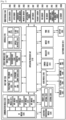
- FIG. 1 is a block diagram illustrating a network environment 100 including an electronic device 101.
- the electronic device 101 includes a bus 110, a processor 120, a memory 130, an input/output interface 150, a display 160, and a communication interface 170.
- the bus 110 may be a circuit designed for connecting the above-discussed elements and communicating data (e.g., a control message) between such elements.
- the processor 120 may receive commands from the other elements (e.g., the memory 130, the input/output interface 150, the display 160, or the communication interface 170, etc.) through the bus 110, interpret the received commands, and perform arithmetic or data processing based on the interpreted commands.
- the other elements e.g., the memory 130, the input/output interface 150, the display 160, or the communication interface 170, etc.
- the memory 130 may store therein commands or data received from or created at the processor 120 or other elements (e.g., the input/output interface 150, the display 160, or the communication interface 170, etc.).
- the memory 130 may include programming modules 140 such as a kernel 141, a middleware 143, an application programming interface (API) 145, and an application 147.
- Each of the programming modules may be composed of software, firmware, hardware, and any combination thereof.
- the kernel 141 may control or manage system resources (e.g., the bus 110, the processor 120, the memory 130, etc.) used to execute operations or functions implemented by other programming modules (e.g., the middleware 143, the API 145, and the application 147). Also, the kernel 141 may provide an interface capable of accessing and controlling or managing the individual elements of the electronic device 101 by using the middleware 143, the API 145, or the application 147.
- system resources e.g., the bus 110, the processor 120, the memory 130, etc.
- other programming modules e.g., the middleware 143, the API 145, and the application 147.
- the kernel 141 may provide an interface capable of accessing and controlling or managing the individual elements of the electronic device 101 by using the middleware 143, the API 145, or the application 147.
- the middleware 143 may serve to go between the API 145 or the application 147 and the kernel 141 in such a manner that the API 145 or the application 147 communicates with the kernel 141 and exchanges data therewith. Also, in relation to work requests received from one or more applications 147 and/or the middleware 143, for example, may perform load balancing of the work requests by using a method of assigning a priority, in which system resources (e.g., the bus 110, the processor 120, the memory 130, etc.) of the electronic device 101 may be used by one or more applications 147.
- system resources e.g., the bus 110, the processor 120, the memory 130, etc.
- the API 145 is an interface through which the application 147 is capable of controlling a function provided by the kernel 141 or the middleware 143, and may include, for example, at least one interface or function for file control, window control, image processing, character control, and the like.
- the memory 130 can also store instructions that, when executed by the processor, causes the plurality of touch displays to be selectively turned on and off based on the orientation and rotation of the electronic device.
- the input/output interface 150 may deliver commands or data, entered by a user through an input/output unit (e.g., a sensor, a keyboard, or a touch screen), to the processor 120, the memory 130, or the communication interface 170 via the bus 110.
- the input/output unit 150 can include a rotation sensor such as a gyro sensor.
- the display 160 may include, for example, a screen such as a liquid crystal display (LCD), a light emitting diode (LED) display, an organic LED (OLED) display, a micro electro mechanical system (MEMS) display, or an electronic paper display.
- the display 160 may display various types of content (e.g., text, images, videos, icons, or symbols) for users.
- the display 160 may include a touch panel, and may receive, for example, a touch, gesture, proximity, or hovering input by using an electronic device or a part of the user's body.
- the communication interface 170 may perform communication between the electronic device 101 and the electronic device 104 or the server 106.
- the communication interface 170 may communicate with any external device by being connected with a network 162 through a wired or wireless communication.
- the wireless communication may include, but not limited to, at least one of wireless fidelity (WiFi), Bluetooth (BT), near field communication (NFC), global navigation satellite system (GNSS), or a cellular communication (e.g., machine type communications (MTC), fifth generation (5G), long term evolution (LTE), long term evolution advanced (LTE-A), code division multiple access (CDMA), wideband code division multiple access (WCDMA), universal mobile telecommunications system (UMTS), wireless broadband (WiBro), global system for mobile communications (GSM), etc.).
- the GNSS may include at least one of global positioning system (GPS), global navigation satellite system (Glonass), Beidou navigation satellite system (Beidou), Galileo, or the European global satellite-based navigation system.
- the wired communication may include, at least one of universal serial bus (USB), high definition multimedia interface (HDMI), RS-232 (recommended standard 232), or plain old telephone service (POTS).
- the network 162 includes, as a telecommunications network at least one of a computer network (e.g., local area network (LAN) or wide area network (WAN)), the Internet, and a telephone network.
- the types of the first and second external electronic devices 102 and 104 may be the same as or different from the type of the electronic device 101.
- the server 106 may include a group of one or more servers. A portion or all of operations performed in the electronic device 101 may be performed in one or more other electronic devices 102, 104 or the server 106. In the case where the electronic device 101 performs a certain function or service automatically or in response to a request, the electronic device 101 may request at least a portion of functions related to the function or service from another electronic device 102, 104 or the server 106 instead of, or in addition to, performing the function or service for itself.
- the other electronic device 102, 104 or the server 106 may perform the requested function or additional function, and may transfer a result of the performance to the electronic device 101.
- the electronic device 101 may additionally process the received result to provide the requested function or service.
- a cloud computing technology, a distributed computing technology, or a client-server computing technology may be used.
- FIG. 2 is a block diagram illustrating an electronic device 201.
- the electronic device 201 may form, for example, the whole or part of the electronic device 101 shown in FIG. 1 .
- the electronic device 201 includes at least one application processor (AP) 210, a communication module 220, a subscriber identification module (SIM) card 224, a memory 230, a sensor module 240, an input unit 250, a display 260, an interface 270, an audio module 280, a camera module 291, a power management module 295, a battery 296, an indicator 297, and a motor 298.
- AP application processor
- SIM subscriber identification module
- the AP 210 may drive an operating system or applications, control a plurality of hardware or software components connected thereto, and also perform processing and operation for various data including multimedia data.
- the AP 210 may be formed of a system-on-chip (SoC), for example.
- SoC system-on-chip
- the AP 210 may further include a graphic processing unit (GPU).
- GPU graphic processing unit
- the communication module 220 may perform data communication with the electronic device 104 or the server 106 connected to the electronic device 201 (e.g., the electronic device 101) through the network.
- the communication module 220 may include therein a cellular module 221, a WiFi module 223, a BT module 225, a GNSS module 227, an NFC module 228, and an RF (radio frequency) module 229.
- the cellular module 221 may offer a voice call, a video call, a message service, an internet service, and the like through a communication network (e.g., machine type communications (MTC), fifth generation (5G), long term evolution (LTE), long term evolution advanced (LTE-A), code division multiple access (CDMA), wideband code division multiple access (WCDMA), universal mobile telecommunications system (UMTS), wireless broadband (WiBro), global system for mobile communications (GSM), wireless fidelity (Wi-Fi), Bluetooth, and near field communications (NFC) etc.).
- MTC machine type communications
- 5G fifth generation
- LTE long term evolution
- LTE-A long term evolution advanced
- CDMA code division multiple access
- WCDMA wideband code division multiple access
- UMTS universal mobile telecommunications system
- WiBro wireless broadband
- GSM global system for mobile communications
- Wi-Fi wireless fidelity
- Bluetooth wireless fidelity
- NFC near field communications
- the cellular module 221 may perform at least part of a multimedia control function.
- Each of the WiFi module 223, the BT module 225, the GNSS module 227 and the NFC module 228 may include a processor for processing data transmitted or received.
- FIG. 2 shows the cellular module 221, the WiFi module 223, the BT module 225, the GNSS module 227 and the NFC module 228 as different blocks, at least part of them may be contained in a single IC (integrated circuit) chip or a single IC package.
- the RF module 229 may transmit and receive data, e.g., RF signals or any other electric signals.
- the RF module 229 may include a transceiver, a PAM (power amp module), a frequency filter, an LNA (low noise amplifier), and the like.
- FIG. 2 shows that the cellular module 221, the WiFi module 223, the BT module 225, the GNSS module 227 and the NFC module 228 share the RF module 229, at least one of them may perform transmission and reception of RF signals through a separate RF module.
- the SIM card 224 may include, for example, an embedded SIM including a user identification module, and may include unique identification information (e.g., an integrated circuit card identifier (ICCID)) or subscriber information (e.g., international mobile subscriber identity (IMSI)).
- ICCID integrated circuit card identifier
- IMSI international mobile subscriber identity
- the memory 230 includes an internal memory 232 and an external memory 234.
- the memory 230 may be, for example, the memory 130 illustrated in FIG. 1 .
- the internal memory 232 may include, for example, at least one of a volatile memory (e.g., a dynamic RAM (DRAM), a static RAM (SRAM), a synchronous dynamic RAM (SDRAM), etc.), and a non-volatile memory (e.g., a one time programmable ROM (OTPROM), a programmable ROM (PROM), an erasable and programmable ROM (EPROM), an electrically erasable and programmable ROM (EEPROM), a mask ROM, a flash ROM, a not AND (NAND) flash memory, a not OR (NOR) flash memory, etc.).
- a volatile memory e.g., a dynamic RAM (DRAM), a static RAM (SRAM), a synchronous dynamic RAM (SDRAM), etc.
- a non-volatile memory e
- the internal memory 232 may be in the form of a solid state drive (SSD).
- the external memory 234 may further include a flash drive, for example, a compact flash (CF), a secure digital (SD), a micro-secure digital (micro-SD), a mini-secure digital (mini-SD), an extreme digital (xD), a memory stick, and the like.
- the external memory 234 may be functionally connected to the electronic device 201 through various interfaces.
- the sensor module 240 may measure physical quantity or sense an operating status of the electronic device 201, and then convert measured or sensed information into electric signals.
- the sensor module 240 includes, for example, at least one of a gesture sensor 240A, a gyro sensor 240B, an atmospheric sensor 240C, a magnetic sensor 240D, an acceleration sensor 240E, a grip sensor 240F, a proximity sensor 240G, a color sensor 240H (e.g., RGB (red, green, blue) sensor), a biometric sensor 240I, a temperature-humidity sensor 240J, an illumination sensor 240K, and a UV (ultraviolet) sensor 240M.
- the sensor module 240 may include, e.g., an E-nose sensor, an EMG (electromyography) sensor, an EEG (electroencephalogram) sensor, an ECG (electrocardiogram) sensor, an IR (infrared) sensor, an iris scan sensor, or a finger scan sensor. Also, the sensor module 240 may include a control circuit for controlling one or more sensors equipped therein.
- the gyro sensor 240B can detect rotation of the electronic device 201.
- the input unit 250 includes a touch panel 252, a digital pen sensor 254, a key 256, or an ultrasonic input unit 258.
- the touch panel 252 may recognize a touch input in a manner of capacitive type, resistive type, infrared type, or ultrasonic type.
- the touch panel 252 may further include a control circuit.
- the touch panel 252 may further include a tactile layer. In this case, the touch panel 252 may offer a tactile feedback to a user.
- the pen sensor 254 e.g., a digital pen sensor
- the ultrasonic input unit 258 enables the terminal to sense a sound wave by using a microphone 288 of the terminal through a pen generating an ultrasonic signal, and to identify data.
- the display 260 (e.g., the display 150) includes a display panel 262, a hologram 264, or a projector 266.
- the display panel 262 may have a flexible, transparent or wearable form.
- the display panel 262 may be formed of a single module with the touch panel 252.
- the hologram 264 may show a stereoscopic image in the air using interference of light.
- the projector 266 may project an image onto a screen, which may be located at the inside or outside of the electronic device 201.
- the display 260 may further include a control circuit for controlling the display panel 262, the hologram 264, and the projector 266.
- the interface 270 may include, for example, an HDMI (high-definition multimedia interface) 272, a USB (universal serial Bus) 274, an optical interface 276, or a D-sub (D-subminiature) 278.
- the interface 270 may be contained, for example, in the communication interface 170 shown in FIG. 1 .
- the interface 270 may include, for example, an MHL (mobile high-definition link) interface, an SD (secure digital) card/MMC (multi-media card) interface, or an IrDA (infrared data association) interface.
- the audio module 280 may perform a conversion between sounds and electric signals. At least part of the audio module 280 may be contained, for example, in the input/output interface 150 shown in FIG. 1 .
- the audio module 280 may process sound information inputted or outputted through a speaker 282, a receiver 284, an earphone 286, or a microphone 288.
- the camera module 291 is a device capable of obtaining still images and moving images.
- the camera module 291 may include at least one image sensor (e.g., a front sensor or a rear sensor), a lens, an ISP (image signal processor, not shown), or a flash (e.g., LED or xenon lamp, not shown).
- image sensor e.g., a front sensor or a rear sensor
- ISP image signal processor
- flash e.g., LED or xenon lamp, not shown.
- the power management module 295 may manage electric power of the electronic device 201.
- the power management module 295 may include, for example, a PMIC (power management integrated circuit), a charger IC, or a battery charge gauge.
- the PMIC may be implemented by, for example, an IC or an SoC semiconductor.
- Charging methods may be classified into a wired charging method and a wireless charging method.
- a wireless charging type may include, for example, a magnetic resonance type, a magnetic induction type, or an electromagnetic type. Any additional circuit for wireless charging may be further used such as a coil loop, a resonance circuit, or a rectifier.
- the battery gauge may measure the residual charge amount of the battery 296 and a voltage, current or temperature in a charging process.
- the battery 296 may store or create electric power therein and supply electric power to the electronic device 201.
- the battery 296 may be, for example, a rechargeable battery or a solar battery.
- the indicator 297 may show thereon a current status (e.g., a booting status, a message status, or a recharging status) of the electronic device 201 or of its part (e.g., the AP 210).
- the motor 298 may convert an electric signal into a mechanical vibration.
- the electronic device 201 may include a specific processor (e.g., GPU) for supporting a mobile TV. This processor may process media data that comply with standards of DMB (digital multimedia broadcasting), DVB (digital video broadcasting), or MediaFlo.
- DMB digital multimedia broadcasting
- DVB digital video broadcasting
- MediaFlo MediaFlo
- Each of the above-discussed elements of the electronic device disclosed herein may be formed of one or more components, and its name may vary according to the type of the electronic device.
- the electronic device disclosed herein may be formed of at least one of the above-discussed elements without some elements or with additional other elements. Some of the elements may be integrated into a single entity that still performs the same functions as those of such elements before integrated.
- FIG. 3 shows the state in which the electronic device according to various embodiments of this disclosure is used.
- the electronic device 300 includes a first touch display and a second touch display.
- the electronic device 300 may include part of or the entire electronic device 101 shown in FIG. 1 .
- the electronic device 300 may include part of or the entire electronic device 201 shown in FIG. 2 .
- the first touch display 310 may be called a main touch display or front touch display
- the second touch display 320 may be called a sub-touch display or back touch display.
- a first display panel included in the first touch display 310 may be called a main display panel or front display panel, and a first touch panel included in the first touch display 310 may be called a main touch panel or front touch panel.
- a second display panel included in the second touch display 320 may be called a sub-display panel or back display panel, and a second touch panel included in the second touch display 320 may be called a sub-touch panel or back touch panel.
- the main touch display or front touch display may be the touch display of a surface in which for example, a home button or a speaker has been located.
- a user may hold the electronic device 300 so that the first touch display 310 faces a first direction and the second touch display 320 faces a second direction, that is, a direction opposite the first direction.
- the first direction may be a direction that faces the user's line of sight, for example.
- the second direction may be a direction facing the user's palm, that is, the direction opposite the first direction, for example.
- an angle between the first direction and the second direction may be at least some of values in the range of 150° to 210°, for example, and may be preferably 180°.
- the first display panel and first touch panel included in the first touch display 310 that faces the first direction may be an on state.
- the on state of the first display panel may include the state in which information is displayed on a display panel of the first touch display 310, for example.
- the on state of the first display panel may include the state in which the first display panel is activated, the backlight is on, the first display panel is powered on or at least some of organic light-emitting diode (OLED) pixels forming the first display panel are on.
- OLED organic light-emitting diode
- the on state of the first touch panel may include the state in which information about touch input of a user through the first touch panel is processed. That is, a touch input is detected, and for example, objects displayed at the location of the touch are, for example, selected in a manner analogous to double-clicking with a mouse.
- the on state of the first touch panel may include the state in which the first touch panel is activated or the amount of charges provided by the first touch panel is a specific value or more so that the first touch panel senses a touch.
- the user may turn the electronic device 300 about a vertical axis Y (or may turn the electronic device 300 over such that the left and right edges swap).
- the user may turn the electronic device 300 about a horizontal axis X (or may turn the electronic device 300 over such that the top and bottom edges swap).
- the turning of the electronic device about an axis may include the first touch display 310 turns to face the second direction on the basis of the axis and the second touch display 320 turns to face the first direction on the basis of the axis.
- the vertical axis Y shall be considered the axis that traverses the electronic device through the center along its longer dimension, while the horizontal axis shall be considered the axis that traverses through the center of the electronic device along the shorter dimension.
- the rotation detection sensor of the electronic device 300 may sense the rotation of the electronic device 300.
- the rotation detection sensor may include at least one of a gyro sensor 240B which senses angular velocity and a rotation angle of the electronic device 300 and an acceleration sensor 240E which senses the acceleration of the electronic device 300, for example.
- the rotation detection sensor may sense the rotation of the electronic device 300 while the electronic device 300 starts to rotate and the rotation is completed.
- the electronic device 300 may change each of the first display panel and the first touch panel, included in the first touch display 310, from the on state to the off state based on a rotation value sensed according to the rotation of the electronic device 300. Furthermore, the electronic device 300 may change each of the second display panel and the second touch panel, included in the second touch display 320, from the off state to the on state.
- the rotation value is at least one of a value of angular velocity, a value of the angle of rotation and a value of the acceleration of gravity, for example.
- the user may hold the electronic device 300 so that the first touch display 310 faces the second direction and the second touch display 320 faces a direction opposite the second direction, that is, the first direction that is facing the direction of the user's line of sight, as in FIG. 3(c) .
- the second display panel and second touch panel included in the second touch display 320 may be in the on state.
- first display panel and first touch panel included in the first touch display 310 may be in the off state.
- the off state of the first display panel may include the state in which no information is displayed on a screen of the first touch display 310, for example.
- the off state of the first display panel may include the state in which the first display panel is deactivated, the first display panel is powered off, organic light-emitting diode (OLED) pixels forming the first display panel are turned off, it is difficult to identify information on a screen of the first touch display 310 with the naked eye because the output voltage of a lamp driver which controls brightness of the pixels is low, or the display panel of the first touch display 310 is displayed as all black pixels.
- OLED organic light-emitting diode
- the off state of the first display panel may include the state in which no information is displayed on most (85% or more) of the display panel of the first touch display 310.
- the first display panel is a flexible display panel and divided into a main region that occupies most of a screen and an edge region that occupies part of a screen, the first display panel may be said to be the off state although information is not displayed in the main region, but information is displayed in the edge region.
- the off state of the first touch panel may include the state in which information about touch input of a user through the first touch panel is not processed, for example.
- the off state of the first touch panel may include the state in which the first touch panel is deactivated, the amount of charges provided by the first touch panel is limited to a specific value or less so that the first touch panel does not sense a touch, or at least one of elements related to touch sensing is deactivated.
- the off state of the first touch panel may include the state in which the processor of the electronic device 300 performs null processing on an output value regarding touch input or does not provide any feedback corresponding to the touch input although it receives information regarding the touch input (e.g., a touch location, a touch direction or a touch time) from the first touch panel.
- Figure 3 shows the electronic device 300 turning about a stationary axis X or Y
- the electronic device 300 can turn about a moving axis such as when revolving.
- the gyro sensor 240B and the acceleration sensor 240E can provide values to the processor.
- the processor can use the foregoing values to translate the revolution as a rotation about a stationary axis. Therefore, rotation shall also be understood to include angular movement about a moving axis.
- FIG. 4 is a block diagram of the electronic device 300 according to the claimed invention.
- the electronic device 300 may be at least one of the aforementioned electronic devices 101 and 201. A description of elements identical with or similar to the elements of the aforementioned electronic device is omitted.
- the electronic device 300 includes a processor 330, a first touch display 310, a second touch display 320, a rotation detection sensor 350 and memory 340.
- the first touch display 310 and the second touch display 320 may include part of or the entire touch panel 262 and display panel 266 of a first one of the plurality of displays 260.
- the first touch display 310 includes a first display panel 311 and a first touch panel 312.
- the first display panel 311 may receive an output signal from the processor 330 and display information.
- the first touch panel 312 may transfer an input signal, generated by a touch of a user, to the processor 330.
- the second touch display 320 includes a second display panel 321 and a second touch panel 322.
- the second display panel 321 may receive an output signal from the processor 330 and display information.
- the first touch panel 322 may transfer an input signal, generated by a touch of a user, to the processor 330.
- the first touch display 310 and the second touch display 320 may constitute a continuous planar screen viewable from a common direction and touch panel thereon, or thereunder.
- a set of OLEDs that are directly connected to each other forming a planar surface viewable from a common direction and touch panel thereon can be considered a first touch display
- another set of OLEDs forming a planar surface and touch panel thereon along the same plane as the first touch display that are not connected to the first touch display or connected by an element that is not an OLED may be considered a second touch display.
- a portion of the OLEDs and the touch panel forms a first planar surface and another portion of the OLEDs and the touch panel forms a second planar surface
- that portion of the OLEDs and touch panel that forms the first planar surface shall be deemed one touch display
- that portion of the OLEDs and touch panel that forms the second planar surface shall be deemed another touch display.
- the rotation detection sensor 350 is configured to generate a rotation value by sensing the rotation of the electronic device 300.
- the rotation detection sensor 350 may include at least one of a gyro sensor 240B which senses the rotation speed of the electronic device 300 and an acceleration sensor 240E which senses the acceleration of the electronic device 300 when the electronic device 300 turns on an axis.
- a gyro sensor 240B which senses the rotation speed of the electronic device 300
- an acceleration sensor 240E which senses the acceleration of the electronic device 300 when the electronic device 300 turns on an axis.
- the characteristics of the gyro sensor 240B and the acceleration sensor 240E will be described later in detail with reference to FIG. 6 .
- the rotation detection sensor 350 may generate at least one of a value of angular velocity and a value of the angle of rotation according to the rotation of the electronic device 300 as a rotation value.
- at least part of the rotation value may be generated by the processor 330.
- the processor 330 may generate the value of the angle of rotation by integrating the value of angular velocity.
- the rotation detection sensor 350 may generate a value of the acceleration according to the rotation of the electronic device 300 as a rotation value.
- the processor 330 may control the overall operation and function of the electronic device 300.
- the processor 330 may include part of or the entire processor 120 of FIG. 1 .
- the processor 330 may include part of or the entire processor 210 of FIG. 2 .
- the processor 330 is electrically connected to the first touch display 310, the second touch display 320 and the rotation detection sensor 350. Furthermore, the processor 330 may be electrically connected to the memory 340 and may fetch an instruction stored in the memory 340. When the electronic device turns on about an axis, the processor 330 may change each of the first touch panel 312 and the first display panel 311 from the on state to the off state and change each of the second touch panel 322 and the second display panel 321 from the off state to the on state based on at least one rotation value received from the rotation detection sensor 350 in accordance with operation based on the fetched instruction.
- the memory 340 is electrically connected to the processor 330.
- the memory 340 stores instructions capable of driving the processor.
- the memory stores instructions that control the processor 330 so that it changes each of the first touch panel 312 and the first display panel 311 from the on state to the off state and it changes each of the second touch panel 322 and the second display panel 321 from the off state to the on state based on at least one rotation value received from the rotation detection sensor 350 when the electronic device 300 turns on the axis.
- the memory 340 may store instructions that control the processor 330 so that it changes each of the first touch panel 312 and the first display panel 311 from the on state to the off state and it changes each of the second touch panel 322 and the second display panel 321 from the off state to the on state if a value of angular velocity sensed by the gyro sensor is a first critical value or more and an acceleration value sensed by the acceleration sensor is a second critical value or more.
- the memory 340 stores instructions that control the processor 330 so that it changes each of the first touch panel and the first display panel from the on state to the off state and it changes each of the second touch panel and the second display panel from the off state to the on state if a rotation time of the electronic device 300 is a critical time or less.
- the memory 340 may store instructions that control the processor 330 so that it deactivates a screen change function for providing a change between a horizontal mode screen and a portrait mode screen based on at least one rotation value received from the rotation detection sensor when the electronic device 300 turns on the virtual axis.
- FIGS. 5A to 5C are diagrams showing electronic devices including a plurality of touch displays according to various embodiments of the present disclosure.
- FIG. 5A is a diagram showing the electronic device 300 including touch displays on both sides (the front and the back). (a) of FIG. 5A is a diagram showing the front of the electronic device 300, and (b) of FIG. 5A is a diagram showing the back of the electronic device 300.
- the first touch display 310 may be provided on the front of the electronic device 300 and the second touch display 320 may be provided on the back of the electronic device 300.
- FIG. 5B is a diagram showing the electronic device 300 of a foldable type.
- the first housing 300a and second housing 300b of the electronic device 300 may be folded together by a hinge or a polymer layer.
- the electronic device 300 shown in (a) of FIG. 5B may be folded as in (b) of FIG. 5B .
- the first touch display 310 and the second touch display 320 may be exposed to the outside.
- FIG. 5C is a diagram showing the electronic device of a bendable type including a flexible display.
- a flexible display 500 included in the electronic device of (b) of FIG. 5C may be divided into the first touch display 310 and the second touch display 320.
- that portion of the OLEDs and touch panel thereon 310 form a first planar surface
- the portion of OLEDs and the touch panel thereon 320 form a second planar surface.
- the area of a surface that belongs to the flexible display and in which a speaker or a front camera is located may become the first touch display 310
- the area of a surface that belongs to the flexible display and in which a home button or menu buttons are located may become the second touch display 320.
- first touch display 310 and the second touch display 320 are located in opposite directions as in FIGS. 5A to 5C , a user turns the electronic device 300 over so that the first touch display 310 faces the back in the state in which the first touch display 310 originally faced the front.
- the user may turn the electronic device over so that the second touch display 320 faces the back in the state in which the second touch display 320 originally faced the front.
- the electronic device 300 changes each of the first touch panel and first display panel, included in the first touch display 310, from the on state to the off state and changes each of the second touch panel and second display panel, included in the second touch display 320, from the off state to the on state based on at least one rotation value received from the rotation detection sensor.
- FIG. 6 is a diagram showing the rotation of the electronic device 300 according to an embodiment of the present disclosure.
- the rotation detection sensor included in the electronic device 300 senses the rotation of the electronic device 300 using at least one of various sensors, such as the gyro sensor and the acceleration sensor.
- the rotation detection sensor senses the rotation of the electronic device 300 and transfers a rotation value, measured based on the results of the sensing, to the processor of the electronic device 300.
- the gyro sensor may sense angular velocity indicative of a change in the angle per time with respect to each of the virtual axes: the horizontal axis X, the vertical axis Y and the depth axis Z according to the rotation of the electronic device 300. Furthermore, the gyro sensor may sense (or calculate or obtain) the rotation angle of each of the horizontal axis X, the vertical axis Y and the depth axis Z by integrating a change in the angle per time.
- the rotation angle of the gyro sensor may be expressed by a roll angle ⁇ 1, a pitch angle ⁇ 2 and a yaw angle ⁇ 3, respectively.
- the roll angle ⁇ 1 may indicate a rotation angle around the horizontal axis in FIG. 6 .
- the pitch angle ⁇ 2 may indicate a rotation angle around the vertical axis in FIG. 6 .
- the yaw angle ⁇ 3 may indicate a rotation angle around the depth axis in the FIG. 6 .
- the acceleration sensor may sense the acceleration of each of the virtual axes: the horizontal axis X, the vertical axis Y and the depth axis Z according to the rotation of the electronic device 300.
- the acceleration sensor measures acceleration that is the sum of the motion acceleration of the electronic device 300, but may measure only the acceleration due to gravity (g force) if there is no movement of the electronic device 300.
- g force the acceleration due to gravity
- the acceleration of gravity measured by the acceleration sensor may be 0 m/sec 2 in the horizontal axis and vertical axis components and may be a specific positive value (e.g., +9.8 m/sec 2 ) in the depth axis component only.
- the acceleration of gravity measured by the acceleration sensor may be 0 m/sec 2 in the horizontal axis and vertical axis components and may be a specific negative value (e.g., -9.8 m/sec 2 ) in the depth axis component only.
- the g force measured by the acceleration sensor may be a value other than 0 m/sec 2 in the X axis and Y axis components.
- each of the axes and a corresponding g force may be changed depending on the location to which the sensor has been attached.
- a rotation value such as angular velocity, a rotation angle or the g force sensed by the rotation detection sensor, is transferred to the processor.
- the processor changes each of the first touch panel and the first display panel from the on state to the off state and changes each of the second touch panel and the second display panel from the off state to the on state based on the sensed rotation value.
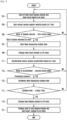
- FIG. 7 is a flowchart illustrating an operation of the electronic device 300 whose state switches according to an embodiment of the present disclosure.
- the main display panel and main touch panel of the electronic device 300 may be the on state, respectively (701).
- the sub-display panel and the sub-touch panel may be the off state, respectively.
- the electronic device 300 may turn on the vertical axis.
- the gyro sensor of the electronic device 300 may sense angular velocity of the electronic device on the basis of the vertical axis (703).
- the electronic device 300 may determine whether the value of the angular velocity based on the vertical axis is a first critical value or more (705).
- the first critical value may be at least one of values in the range of 1 radian (rad)/sec to 3 rad/sec, for example, and may be preferably a value of close to 2 rad/sec.
- the electronic device 300 may determine that the rotation of the electronic device 300 intended by a user has started.
- the electronic device 300 may further determine whether a value of the angle of rotation of the electronic device 300 is a critical angle or more.
- the angle of rotation may be the integral value of angular velocity.
- the critical angle may be at least one of values in the range of 20° to 40°, for example, and may be preferably 30°.
- the electronic device 300 may determine whether both the value of the angular velocity and value of the angle of rotation of the electronic device 300 are the critical value or more. If both the value of the angular velocity and value of the angle of rotation of the electronic device 300 are the critical value or more, the electronic device 300 may determine that the rotation of the electronic device 300 intended by the user has started. Alternatively, if one of the value of the angular velocity and the value of the angle of rotation is the critical value or more, the electronic device 300 may determine that the rotation of the electronic device 300 intended by the user has started.
- the electronic device 300 If the rotation of the electronic device 300 intended by the user has started, the electronic device 300 starts a timer which measures a rotation time (707) and may change the main touch module from the on state to the off state (709).
- the electronic device 300 may determine that the rotation of the electronic device 300 is not intended by the user to completely turn over the electronic device 300 and maintain each of the main display panel and main touch panel of the electronic device 300 in the on state.
- the acceleration sensor of the electronic device 300 may sense an acceleration of the electronic device on the basis of the depth axis (711).
- the electronic device 300 determines whether the value of the acceleration based on the depth axis is a second critical value or more (713).
- the second critical value may be at least one of values in the range of 2 m/sec 2 to 5 m/sec 2 , for example, and may be preferably 3 m/sec 2 .
- the second critical value may be at least one of values in the range of -5 m/sec 2 to -2 m/sec 2 and may be preferably -3 m/sec 2 .
- the electronic device 300 determines that the rotation of the electronic device has been terminated.
- the electronic device 300 terminates the timer which measures the rotation time (715).
- the electronic device 300 may determine that the rotation of the electronic device 300 is not intended to turn over the electronic device 300 by the user and maintain each of the main display panel and main touch panel of the electronic device 300 in the on state.
- the electronic device 300 determines the rotation time of the electronic device 300 based on the time counted by the timer.
- the electronic device 300 determines whether the determined rotation time of the electronic device 300 is a critical time or less (717).
- the critical time may be at least one of values 100 ms to 300 ms, for example, and may be preferably about 200 ms.
- the electronic device 300 determines that the rotation of the electronic device 300 is a rotation intended by the user.
- the electronic device 300 may determine that the rotation of the electronic device 300 is not intended by the user to turn over the electronic device 300 and maintain each of the main display panel and main touch panel of the electronic device 300 in the on state.
- the electronic device 300 If the rotation time is the critical time or less, the electronic device 300 generates an event for changing the state of the touch display of the electronic device 300.
- the electronic device 300 changes the main display panel from the on state to the off state (719).
- the electronic device 300 changes each of the sub-display panel and the sub-touch panel from the off state to the on state (721).
- FIG. 8 is a flowchart illustrating an operation of the electronic device whose state switches according to another embodiment of the present disclosure.
- an operation 801 to an operation 819 correspond to the operation 701 to operation 719 of FIG. 7 .
- the electronic device 300 changes each of the sub-display panel and the sub-touch panel from the off state to the on state (821).
- the front of the sub-touch display including the sub-display panel and the sub-touch panel may face the user.
- the electronic device 300 may turn on the vertical axis again.
- the gyro sensor of the electronic device 300 may sense angular velocity of the electronic device on the basis of the vertical axis (823).
- the electronic device 300 may determine whether the value of the angular velocity based on the vertical axis is a third critical value or more (825).
- the third critical value may be a value identical with or similar to the first critical value of the operation 805.
- the electronic device 300 may determine that the rotation of the electronic device 300 intended by the user has started.
- the electronic device 300 starts a timer which measures a rotation time (827) and may change the sub-touch module from the on state to the off state (829).
- the electronic device 300 may determine that the rotation of the electronic device 300 is not intended by the user to turn over the electronic device 300 and maintain each of the sub-display panel and sub-touch panel of the electronic device 300 in the on state.
- the acceleration sensor of the electronic device 300 may sense an acceleration of the electronic device on the basis of the depth axis (831).
- the electronic device 300 determines whether the acceleration value based on the depth axis is a fourth critical value or more (833).
- the fourth critical value may be a value identical with or similar to the second critical value of the operation 813.
- the electronic device 300 determines that the rotation of the electronic device has been terminated.
- the electronic device 300 terminates the timer which measures the rotation time (835).
- the electronic device 300 may determine that the rotation of the electronic device 300 is not intended by the user to turn over the electronic device 300 and maintain each of the sub-display panel and sub-touch panel of the electronic device 300 in the on state.
- the electronic device 300 determines the rotation time of the electronic device 300 based on the time counted by the timer.
- the electronic device 300 may determine whether the determined rotation time of the electronic device 300 is a second critical time or less (837).
- the second critical time may be a value identical with or similar (within 2%) to the first critical time of the operation 817.
- the electronic device 300 determines that the rotation of the electronic device 300 is a rotation intended by the user to turn the electronic device 300 over.
- the electronic device 300 may determine that the rotation of the electronic device 300 is not a rotation intended by the user to turn over the electronic device 300 and maintain each of the sub-display panel and sub-touch panel of the electronic device 300 in the on state.
- the electronic device 300 changes the sub-display panel from the on state to the off state (839).
- the electronic device 300 changes each of the main display panel and the main touch panel from the off state to the on state again (841).
- the operation 841 may correspond to the operation 801. Accordingly, the state of the plurality of touch displays of the electronic device may continue to switch in response to the rotation of the electronic device 300. That is, in response to the rotation of the electronic device 300, the main display panel and the main touch panel switch from the on state to the off state. In response thereto, the sub-display panel and the sub-touch panel switch from the off state to the on state. Furthermore, in response to the rotation of the electronic device 300, the sub-display panel and the sub-touch panel switch from the on state to the off state. In response thereto, the main display panel and the main touch panel switch from the off state to the on state.
- FIG. 9 is a flowchart illustrating an operation of the electronic device whose state switches according to yet another embodiment of the present disclosure.
- the electronic device 300 may be displaying a screen in the portrait mode (901).
- the electronic device 300 may turn on the vertical axis.
- the gyro sensor of the electronic device 300 may sense angular velocity of the electronic device on the basis of the vertical axis (903).
- the electronic device 300 may determine whether the value of the angular velocity based on the vertical axis is a first critical value or more (905).
- the electronic device 300 may determine that the rotation of the electronic device 300 intended by a user to turn over the electronic device 300 has started.
- the electronic device 300 may start a timer which measures a rotation time (907).
- the electronic device 300 may deactivate the screen change function for providing a change between the landscape mode screen and the portrait mode screen in response to a change in the direction of the electronic device 300.
- the electronic device 300 may set an orientation change event to be off so that the orientation change event is not generated in response to a change in the direction of the electronic device 300 (909).
- the electronic device 300 may change the main display panel from the on state to the off state and the sub-display panel from the off state to the on state based on the acceleration value of the electronic device sensed on the basis of the depth axis of the electronic device 300 and the rotation time measured by the timer.
- Corresponding operations 911 to 921 correspond to the operations 711 to 721 of FIG. 7 .
- the electronic device 300 may determine that the rotation of the electronic device 300 is not intended by the user to turn over the electronic device 300 and maintain each of the main display panel and main touch panel of the electronic device 300 in the on state.
- the electronic device 300 may continue to activate the screen change function for providing a change between the landscape mode screen and portrait mode screen of the electronic device 300.
- the electronic device 300 may set an orientation change event to be on so that the orientation change event is generated in response to a change in the direction of the electronic device 300 (931).
- the electronic device 300 may determine whether the orientation change event at which the direction of the electronic device 300 switches is generated (933).
- the electronic device 300 may change a screen of the electronic device 300 from the portrait mode screen to the landscape mode screen (935).
- FIG. 10 is a flowchart illustrating an operation of the electronic device whose state switches according to another embodiment of the present disclosure.
- the electronic device 300 controls the first touch panel and the first display panel so that each of them becomes the on state (1001).
- the electronic device 300 determines whether the electronic device 300 turns on an axis using the rotation detection sensor (1003).
- the electronic device 300 changes each of the first touch panel and the first display panel from the on state to the off state and changes each of the second touch panel and the second display panel from the off state to the on state based on at least one rotation value sensed in response to the rotation of the electronic device 300 (1005).
- the electronic device 300 changes each of the first touch panel and the first display panel from the on state to the off state and change each of the second touch panel and the second display panel from the off state to the on state.
- a rotation time of the electronic device 300 is a critical time or less, the electronic device 300 changes each of the first touch panel and the first display panel from the on state to the off state and changes each of the second touch panel and the second display panel from the off state to the on state.
- the electronic device 300 may deactivate the screen change function for providing a change between the landscape mode screen and the portrait mode screen based on at least one rotation value received from the rotation detection sensor.
- module may refer to a certain unit that includes one of hardware or hardware with instructions stored in memory.
- the term module may be interchangeably used with unit, logic, logical block, component, or circuit, for example.
- the module may be the minimum unit, or part thereof, which performs one or more particular functions.
- the module may be formed mechanically or electronically.
- the module disclosed herein may include at least one of ASIC (application-specific integrated circuit) chip, FPGAs (field-programmable gate arrays), and programmable-logic device, which have been known or are to be developed.
- ASIC application-specific integrated circuit
- FPGAs field-programmable gate arrays
- a recording medium such as a CD ROM, a Digital Versatile Disc (DVD), a magnetic tape, a RAM, a floppy disk, a hard disk, or a magneto-optical disk or computer code downloaded over a network originally stored on a remote recording medium or a non-transitory machine readable medium and to be stored on a local recording medium, so that the methods described herein can be rendered via such software that is stored on the recording medium using a general purpose computer, or a special processor or in programmable or dedicated hardware, such as an ASIC or FPGA.
- a recording medium such as a CD ROM, a Digital Versatile Disc (DVD), a magnetic tape, a RAM, a floppy disk, a hard disk, or a magneto-optical disk or computer code downloaded over a network originally stored on a remote recording medium or a non-transitory machine readable medium and to be stored on a local recording medium, so that the methods described herein can be rendered via such software that is stored
- the computer, the processor, microprocessor controller or the programmable hardware include memory components, e.g., RAM, ROM, Flash, etc. that may store or receive software or computer code that when accessed and executed by the computer, processor or hardware implement the processing methods described herein.
- memory components e.g., RAM, ROM, Flash, etc. that may store or receive software or computer code that when accessed and executed by the computer, processor or hardware implement the processing methods described herein.
Description
- Various embodiments of the present disclosure relate to an electronic device and a method for changing the state of the electronic device and, more particularly, to an electronic device including a plurality of touch displays and a method for changing the state of the electronic device.
- An electronic device may include a display. The thickness and weight of the electronic device with display mounted thereon have been significantly reduced. The display is capable of providing various functions that simplify usage of the device and allow portability.
- Shortcomings and disadvantages of conventional and traditional approaches will become apparent through comparison of such systems through comparison to certain aspects of embodiments presented in the remainder of the application and drawings.
EP 1 843 563 A1US 2010/245209 A1 andUS 2013/050164 A1 are acknowledged as further prior art. - From among electronic devices, there may be an electronic device including a plurality of touch displays. In the electronic device including the plurality of touch displays, a user may optionally use a first touch display and second touch display that form the plurality of touch displays.
- For example, in a process of performing, by the user, a task using the first touch display, the user may perform a task using the second touch display again.
- Alternatively, when the front of the first touch display and the front of the second touch display are located on the same plane, the user may use the first touch display and the second touch display together as a single screen. For example, the user may move or copy content being displayed on a screen of the first touch display to a screen of the second touch display.
- Alternatively, when the first touch display and the second touch display maintain a specific angle, the user may use the first touch display as a main display and use also the second touch display as a sub-display. For example, when content is displayed on a screen of the first touch display, a UI capable of manipulating the content may be displayed on the second touch display.
- In an electronic device including a plurality of touch displays, a first touch display and a second touch display may be located in opposite directions.
- In this situation, while a user performs a task using the first touch display, the user may turn the electronic device over in order to perform a task using the second touch display. In this case, the user performs inconvenient manipulations for turning off a screen of the first touch display, turning the electronic device over, and turning on a screen of the second touch display again.
- Furthermore, while turning the electronic device over, the user may inadvertently touch the first touch display or the second touch display, thereby resulting in a malfunction of the electronic device.
- Accordingly, an object of an electronic device according to the present disclosure is to prevent inconvenience in a user manipulation and an unwanted malfunction of the electronic device when the user tries to use a second touch display while the user performs a task using a first touch display.
- In addition, technical objects to be achieved by the present disclosure are not limited to the aforementioned object, and those skilled in the art to which the present disclosure pertains may evidently understand other technological objects from the following description.
- An electronic device including a plurality of touch displays according to various embodiments of the present disclosure includes features defined in the appended independent device claim.
- According to various embodiments of the present disclosure, a method is provided with the steps defined in the appended independent method claim.
- A computer-readable non-volatile recording medium according to an embodiment of the present disclosure may store a program which enables an electronic device (or processor) to perform said method.
- In accordance with various embodiments of the present disclosure, when the electronic device turns on an axis, the first display panel and the second display panel automatically switch to the on state or the off state. Accordingly, the usability of a user who uses the electronic device can be significantly improved because the one of the first touch display and the second touch display that faces the user's line of sight is in an on state, while the other that is not likely to be visible to the user is in an off state.
- Furthermore, when the electronic device turns on an axis, the first touch panel and the second touch panel automatically switch to the on state or the off state. Accordingly, an operation of the electronic device due to an unintended touch of the touch panel can be prevented.
- Furthermore, when the electronic device turns on a virtual axis, the screen change function between a landscape mode screen and a portrait mode screen is temporarily deactivated. Accordingly, an unintended operation of the electronic device when turning can be prevented.
- In addition, an effect which may be obtained or predicted through an embodiment of the present disclosure is directly or implicitly disclosed in the detailed description according to embodiments of the present disclosure. For example, various effects predicted according to embodiments of the present disclosure will be disclosed in the detailed description to be described.
-
-
FIG. 1 is a diagram showing a network environment including an electronic device that is not claimed but that is useful for implementing the claimed invention. -
FIG. 2 is a block diagram of an electronic device that is not claimed but that is useful for implementing the claimed invention. -
FIG. 3 shows the state in which the electronic device according to various embodiments of the present disclosure is used. -
FIG. 4 is a block diagram of an electronic device according to the claimed invention. -
FIGS. 5A to 5C are diagrams showing electronic devices including a plurality of touch displays according to various embodiments of the present disclosure. -
FIG. 6 is a diagram showing the rotation of the electronic device according to an embodiment of the present disclosure. -
FIGS. 7 to 10 are flowcharts illustrating an operation of the electronic device whose state switches according to an embodiment of the present disclosure. - The following description, with reference to the accompanying drawings, is provided to assist in a comprehensive understanding of the invention as defined by the claims. It includes various specific details to assist in that understanding but are to be regarded as merely exemplary. Accordingly, those of ordinary skill in the art will recognize that various changes and modifications of the embodiments described herein may be made without departing from the scope of the present disclosure. In addition, descriptions of well-known functions and constructions may be omitted for clarity and conciseness.
- Expressions such as "include" and "may include" which may be used in the present disclosure denote the presence of the disclosed functions, operations, and constituent elements and do not limit one or more additional functions, operations, and constituent elements. In the present disclosure, terms such as "include" and/or "have" may be construed to denote a certain characteristic, number, step, operation, constituent element, component or a combination thereof, but may not be construed to exclude the existence of, or a possibility of, the addition of one or more other characteristics, numbers, steps, operations, constituent elements, components or combinations thereof.
- Furthermore, in the present disclosure, the expression "and/or" includes any and all combinations of the associated listed words. For example, the expression "A and/or B" may include A, may include B, or may include both A and B.
- In the present disclosure, expressions including ordinal numbers, such as "first" and "second," etc., may modify various elements. However, such elements are not limited by the above expressions. For example, the above expressions do not limit the sequence and/or importance of the elements. The above expressions are used merely for the purpose to distinguish an element from the other elements. For example, a first user device and a second user device indicate different user devices although both of them are user devices. For example, a first element may be referred to as a second element, and similarly, a second element may also be referred to as a first element without departing from the scope of the present disclosure.
- In the case where a component is referred to as being "connected" to, or "accessed" by another component, it should be understood that the foregoing is not limited to the component directly connected to or accessed by the other component, but may also include the circumstance where there may also exist another component between them. Meanwhile, in the case where a component is referred to as being "directly connected" or "directly accessed" to another component, it should be understood that there is no component therebetween.
- The terms used in the present disclosure are only used to describe specific embodiments, and do not limit the present disclosure. As used herein, the singular forms are intended to include the plural forms as well, unless the context clearly indicates otherwise.
- In the present disclosure, an electronic device may be a device that involves a communication function. For example, an electronic device may be a smart phone, a tablet personal computer (PC), a mobile phone, a video phone, an e-book reader, a desktop PC, a laptop PC, a netbook computer, a personal digital assistant (PDA), a portable multimedia player (PMP), an MP3 player, a portable medical device, a digital camera, or a wearable device (e.g., a head-mounted device (HMD)) such as electronic eyeglasses, electronic clothes, an electronic bracelet, an electronic necklace, an electronic appcessory, or a smart watch).
- According to an embodiment of the present disclosure, an electronic device may be a smart home appliance that involves a communication function. For example, an electronic device may be a TV, a digital video disk (DVD) player, audio equipment, a refrigerator, an air conditioner, a vacuum cleaner, an oven, a microwave, a washing machine, an air cleaner, a set-top box, a TV box (e.g., Samsung HomeSync™, Apple TV™, Google TV™, etc.), a game console, an electronic dictionary, an electronic key, a camcorder, or an electronic picture frame.
- Other embodiments of the electronic device include various medical devices (for example, various kinds of portable medical measuring device (blood glucose meter, heart rate meter, blood pressure meter, or a temperature measuring instrument, etc.), magnetic resonance angiography (MRA), magnetic resonance imaging (MRI), computed tomography (CT), camcorder, etc., navigation (navigation) devices, global positioning system receiver (GPS) receiver, EDR (event data recorder), flight data recorder (FDR), automotive infotainment (infotainment) devices, marine electronic equipment (e.g., marine navigation systems, gyrocompass, etc.), aviation electronics (avionics), security devices, automotive head unit (head unit), industrial or household robots, financial institutions, automatic teller machine (ATM), point of sales (POS) terminals, or Internet of Things (IoT) devices (e.g. light bulbs, various sensors, electric or gas meters, sprinkler systems, fire alarms, thermostat, street lights, toaster, fitness equipment, hot water tank, a heater, a boiler, etc.).
- According to an embodiment of the present disclosure, an electronic device may be furniture or a building / structure of the portion, an electronic board, an electronic sign-receiving device (electronic signature receiving device), a projector, or various measuring devices (e.g. water, electricity, gas, or a radio wave measuring equipment, etc.). The electronic device may be one or more combinations of the various devices described above. The electronic device may be a flexible electronic device. In addition, an electronic device is not limited to the above-described device, and may include a new electronic device, in accordance with new technological developments. In this document, the term user refers to a human or an electronic device using the electronic device (for example, an artificial intelligence electronic device).
-
FIG. 1 is a block diagram illustrating anetwork environment 100 including anelectronic device 101. Referring toFIG. 1 , theelectronic device 101 includes abus 110, aprocessor 120, amemory 130, an input/output interface 150, adisplay 160, and acommunication interface 170. - The
bus 110 may be a circuit designed for connecting the above-discussed elements and communicating data (e.g., a control message) between such elements. - The
processor 120 may receive commands from the other elements (e.g., thememory 130, the input/output interface 150, thedisplay 160, or thecommunication interface 170, etc.) through thebus 110, interpret the received commands, and perform arithmetic or data processing based on the interpreted commands. - The
memory 130 may store therein commands or data received from or created at theprocessor 120 or other elements (e.g., the input/output interface 150, thedisplay 160, or thecommunication interface 170, etc.). Thememory 130 may includeprogramming modules 140 such as akernel 141, amiddleware 143, an application programming interface (API) 145, and anapplication 147. Each of the programming modules may be composed of software, firmware, hardware, and any combination thereof. - The
kernel 141 may control or manage system resources (e.g., thebus 110, theprocessor 120, thememory 130, etc.) used to execute operations or functions implemented by other programming modules (e.g., themiddleware 143, theAPI 145, and the application 147). Also, thekernel 141 may provide an interface capable of accessing and controlling or managing the individual elements of theelectronic device 101 by using themiddleware 143, theAPI 145, or theapplication 147. - The
middleware 143 may serve to go between theAPI 145 or theapplication 147 and thekernel 141 in such a manner that theAPI 145 or theapplication 147 communicates with thekernel 141 and exchanges data therewith. Also, in relation to work requests received from one ormore applications 147 and/or themiddleware 143, for example, may perform load balancing of the work requests by using a method of assigning a priority, in which system resources (e.g., thebus 110, theprocessor 120, thememory 130, etc.) of theelectronic device 101 may be used by one ormore applications 147. - The
API 145 is an interface through which theapplication 147 is capable of controlling a function provided by thekernel 141 or themiddleware 143, and may include, for example, at least one interface or function for file control, window control, image processing, character control, and the like. - The
memory 130 can also store instructions that, when executed by the processor, causes the plurality of touch displays to be selectively turned on and off based on the orientation and rotation of the electronic device. - The input/
output interface 150 may deliver commands or data, entered by a user through an input/output unit (e.g., a sensor, a keyboard, or a touch screen), to theprocessor 120, thememory 130, or thecommunication interface 170 via thebus 110. The input/output unit 150 can include a rotation sensor such as a gyro sensor. - The
display 160 may include, for example, a screen such as a liquid crystal display (LCD), a light emitting diode (LED) display, an organic LED (OLED) display, a micro electro mechanical system (MEMS) display, or an electronic paper display. Thedisplay 160 may display various types of content (e.g., text, images, videos, icons, or symbols) for users. Thedisplay 160 may include a touch panel, and may receive, for example, a touch, gesture, proximity, or hovering input by using an electronic device or a part of the user's body. - The
communication interface 170 may perform communication between theelectronic device 101 and theelectronic device 104 or theserver 106. For example, thecommunication interface 170 may communicate with any external device by being connected with anetwork 162 through a wired or wireless communication. - The wireless communication may include, but not limited to, at least one of wireless fidelity (WiFi), Bluetooth (BT), near field communication (NFC), global navigation satellite system (GNSS), or a cellular communication (e.g., machine type communications (MTC), fifth generation (5G), long term evolution (LTE), long term evolution advanced (LTE-A), code division multiple access (CDMA), wideband code division multiple access (WCDMA), universal mobile telecommunications system (UMTS), wireless broadband (WiBro), global system for mobile communications (GSM), etc.). The GNSS may include at least one of global positioning system (GPS), global navigation satellite system (Glonass), Beidou navigation satellite system (Beidou), Galileo, or the European global satellite-based navigation system. Hereinafter, the terms "GPS" and the "GNSS" may be interchangeably used herein. The wired communication may include, at least one of universal serial bus (USB), high definition multimedia interface (HDMI), RS-232 (recommended standard 232), or plain old telephone service (POTS). The
network 162 includes, as a telecommunications network at least one of a computer network (e.g., local area network (LAN) or wide area network (WAN)), the Internet, and a telephone network. - The types of the first and second external
electronic devices electronic device 101. Theserver 106 may include a group of one or more servers. A portion or all of operations performed in theelectronic device 101 may be performed in one or more otherelectronic devices server 106. In the case where theelectronic device 101 performs a certain function or service automatically or in response to a request, theelectronic device 101 may request at least a portion of functions related to the function or service from anotherelectronic device server 106 instead of, or in addition to, performing the function or service for itself. The otherelectronic device server 106 may perform the requested function or additional function, and may transfer a result of the performance to theelectronic device 101. Theelectronic device 101 may additionally process the received result to provide the requested function or service. To this end, for example, a cloud computing technology, a distributed computing technology, or a client-server computing technology may be used. -
FIG. 2 is a block diagram illustrating anelectronic device 201. Theelectronic device 201 may form, for example, the whole or part of theelectronic device 101 shown inFIG. 1 . Referring toFIG. 2 , theelectronic device 201 includes at least one application processor (AP) 210, acommunication module 220, a subscriber identification module (SIM)card 224, amemory 230, asensor module 240, aninput unit 250, adisplay 260, aninterface 270, anaudio module 280, acamera module 291, apower management module 295, abattery 296, anindicator 297, and amotor 298. - The
AP 210 may drive an operating system or applications, control a plurality of hardware or software components connected thereto, and also perform processing and operation for various data including multimedia data. TheAP 210 may be formed of a system-on-chip (SoC), for example. TheAP 210 may further include a graphic processing unit (GPU). - The communication module 220 (e.g., the communication interface 170) may perform data communication with the
electronic device 104 or theserver 106 connected to the electronic device 201 (e.g., the electronic device 101) through the network. Thecommunication module 220 may include therein acellular module 221, aWiFi module 223, aBT module 225, aGNSS module 227, anNFC module 228, and an RF (radio frequency)module 229. - The
cellular module 221 may offer a voice call, a video call, a message service, an internet service, and the like through a communication network (e.g., machine type communications (MTC), fifth generation (5G), long term evolution (LTE), long term evolution advanced (LTE-A), code division multiple access (CDMA), wideband code division multiple access (WCDMA), universal mobile telecommunications system (UMTS), wireless broadband (WiBro), global system for mobile communications (GSM), wireless fidelity (Wi-Fi), Bluetooth, and near field communications (NFC) etc.). Additionally, thecellular module 221 may perform identification and authentication of the electronic device in the communication network, using theSIM card 224. Thecellular module 221 may perform at least part of functions theAP 210 may provide. For example, thecellular module 221 may perform at least part of a multimedia control function. Each of theWiFi module 223, theBT module 225, theGNSS module 227 and theNFC module 228 may include a processor for processing data transmitted or received. AlthoughFIG. 2 shows thecellular module 221, theWiFi module 223, theBT module 225, theGNSS module 227 and theNFC module 228 as different blocks, at least part of them may be contained in a single IC (integrated circuit) chip or a single IC package. - The
RF module 229 may transmit and receive data, e.g., RF signals or any other electric signals. TheRF module 229 may include a transceiver, a PAM (power amp module), a frequency filter, an LNA (low noise amplifier), and the like. AlthoughFIG. 2 shows that thecellular module 221, theWiFi module 223, theBT module 225, theGNSS module 227 and theNFC module 228 share theRF module 229, at least one of them may perform transmission and reception of RF signals through a separate RF module. - The
SIM card 224 may include, for example, an embedded SIM including a user identification module, and may include unique identification information (e.g., an integrated circuit card identifier (ICCID)) or subscriber information (e.g., international mobile subscriber identity (IMSI)). - The
memory 230 includes aninternal memory 232 and anexternal memory 234. Thememory 230 may be, for example, thememory 130 illustrated inFIG. 1 . Theinternal memory 232 may include, for example, at least one of a volatile memory (e.g., a dynamic RAM (DRAM), a static RAM (SRAM), a synchronous dynamic RAM (SDRAM), etc.), and a non-volatile memory (e.g., a one time programmable ROM (OTPROM), a programmable ROM (PROM), an erasable and programmable ROM (EPROM), an electrically erasable and programmable ROM (EEPROM), a mask ROM, a flash ROM, a not AND (NAND) flash memory, a not OR (NOR) flash memory, etc.). Theinternal memory 232 may be in the form of a solid state drive (SSD). Theexternal memory 234 may further include a flash drive, for example, a compact flash (CF), a secure digital (SD), a micro-secure digital (micro-SD), a mini-secure digital (mini-SD), an extreme digital (xD), a memory stick, and the like. Theexternal memory 234 may be functionally connected to theelectronic device 201 through various interfaces. - The
sensor module 240 may measure physical quantity or sense an operating status of theelectronic device 201, and then convert measured or sensed information into electric signals. Thesensor module 240 includes, for example, at least one of agesture sensor 240A, agyro sensor 240B, anatmospheric sensor 240C, amagnetic sensor 240D, anacceleration sensor 240E, agrip sensor 240F, aproximity sensor 240G, acolor sensor 240H (e.g., RGB (red, green, blue) sensor), a biometric sensor 240I, a temperature-humidity sensor 240J, anillumination sensor 240K, and a UV (ultraviolet)sensor 240M. Additionally or alternatively, thesensor module 240 may include, e.g., an E-nose sensor, an EMG (electromyography) sensor, an EEG (electroencephalogram) sensor, an ECG (electrocardiogram) sensor, an IR (infrared) sensor, an iris scan sensor, or a finger scan sensor. Also, thesensor module 240 may include a control circuit for controlling one or more sensors equipped therein. - The
gyro sensor 240B can detect rotation of theelectronic device 201. - The
input unit 250 includes atouch panel 252, adigital pen sensor 254, a key 256, or anultrasonic input unit 258. Thetouch panel 252 may recognize a touch input in a manner of capacitive type, resistive type, infrared type, or ultrasonic type. Also, thetouch panel 252 may further include a control circuit. Thetouch panel 252 may further include a tactile layer. In this case, thetouch panel 252 may offer a tactile feedback to a user. The pen sensor 254 (e.g., a digital pen sensor), for example, may be implemented by using a method identical or similar to a method of receiving a touch input from the user, or by using a separate sheet for recognition. For example, a key pad or a touch key may be used similar to thekeys 256. Theultrasonic input unit 258 enables the terminal to sense a sound wave by using amicrophone 288 of the terminal through a pen generating an ultrasonic signal, and to identify data. - The display 260 (e.g., the display 150) includes a
display panel 262, ahologram 264, or aprojector 266. Thedisplay panel 262 may have a flexible, transparent or wearable form. Thedisplay panel 262 may be formed of a single module with thetouch panel 252. Thehologram 264 may show a stereoscopic image in the air using interference of light. Theprojector 266 may project an image onto a screen, which may be located at the inside or outside of theelectronic device 201. Thedisplay 260 may further include a control circuit for controlling thedisplay panel 262, thehologram 264, and theprojector 266. - The
interface 270 may include, for example, an HDMI (high-definition multimedia interface) 272, a USB (universal serial Bus) 274, anoptical interface 276, or a D-sub (D-subminiature) 278. Theinterface 270 may be contained, for example, in thecommunication interface 170 shown inFIG. 1 . Additionally or alternatively, theinterface 270 may include, for example, an MHL (mobile high-definition link) interface, an SD (secure digital) card/MMC (multi-media card) interface, or an IrDA (infrared data association) interface. - The
audio module 280 may perform a conversion between sounds and electric signals. At least part of theaudio module 280 may be contained, for example, in the input/output interface 150 shown inFIG. 1 . Theaudio module 280 may process sound information inputted or outputted through aspeaker 282, areceiver 284, anearphone 286, or amicrophone 288. - The
camera module 291 is a device capable of obtaining still images and moving images. Thecamera module 291 may include at least one image sensor (e.g., a front sensor or a rear sensor), a lens, an ISP (image signal processor, not shown), or a flash (e.g., LED or xenon lamp, not shown). - The
power management module 295 may manage electric power of theelectronic device 201. Thepower management module 295 may include, for example, a PMIC (power management integrated circuit), a charger IC, or a battery charge gauge. The PMIC may be implemented by, for example, an IC or an SoC semiconductor. Charging methods may be classified into a wired charging method and a wireless charging method. A wireless charging type may include, for example, a magnetic resonance type, a magnetic induction type, or an electromagnetic type. Any additional circuit for wireless charging may be further used such as a coil loop, a resonance circuit, or a rectifier. The battery gauge may measure the residual charge amount of thebattery 296 and a voltage, current or temperature in a charging process. Thebattery 296 may store or create electric power therein and supply electric power to theelectronic device 201. Thebattery 296 may be, for example, a rechargeable battery or a solar battery. - The
indicator 297 may show thereon a current status (e.g., a booting status, a message status, or a recharging status) of theelectronic device 201 or of its part (e.g., the AP 210). Themotor 298 may convert an electric signal into a mechanical vibration. Theelectronic device 201 may include a specific processor (e.g., GPU) for supporting a mobile TV. This processor may process media data that comply with standards of DMB (digital multimedia broadcasting), DVB (digital video broadcasting), or MediaFlo. - Each of the above-discussed elements of the electronic device disclosed herein may be formed of one or more components, and its name may vary according to the type of the electronic device. The electronic device disclosed herein may be formed of at least one of the above-discussed elements without some elements or with additional other elements. Some of the elements may be integrated into a single entity that still performs the same functions as those of such elements before integrated.
-
FIG. 3 shows the state in which the electronic device according to various embodiments of this disclosure is used. - In
FIG. 3 , theelectronic device 300 includes a first touch display and a second touch display. - Various types of the
electronic device 300 will be described with reference toFIGS. 5A to 5C . Theelectronic device 300 may include part of or the entireelectronic device 101 shown inFIG. 1 . Alternatively, theelectronic device 300 may include part of or the entireelectronic device 201 shown inFIG. 2 . - Furthermore, in the present disclosure, the
first touch display 310 may be called a main touch display or front touch display, and thesecond touch display 320 may be called a sub-touch display or back touch display. - Furthermore, a first display panel included in the
first touch display 310 may be called a main display panel or front display panel, and a first touch panel included in thefirst touch display 310 may be called a main touch panel or front touch panel. - Furthermore, a second display panel included in the
second touch display 320 may be called a sub-display panel or back display panel, and a second touch panel included in thesecond touch display 320 may be called a sub-touch panel or back touch panel. - The main touch display or front touch display may be the touch display of a surface in which for example, a home button or a speaker has been located.
- First, in
FIG. 3(a) , a user may hold theelectronic device 300 so that thefirst touch display 310 faces a first direction and thesecond touch display 320 faces a second direction, that is, a direction opposite the first direction. The first direction may be a direction that faces the user's line of sight, for example. The second direction may be a direction facing the user's palm, that is, the direction opposite the first direction, for example. Furthermore, an angle between the first direction and the second direction may be at least some of values in the range of 150° to 210°, for example, and may be preferably 180°. - In this situation, the first display panel and first touch panel included in the
first touch display 310 that faces the first direction may be an on state. - The on state of the first display panel may include the state in which information is displayed on a display panel of the
first touch display 310, for example. Alternatively, the on state of the first display panel may include the state in which the first display panel is activated, the backlight is on, the first display panel is powered on or at least some of organic light-emitting diode (OLED) pixels forming the first display panel are on. - Furthermore, the on state of the first touch panel may include the state in which information about touch input of a user through the first touch panel is processed. That is, a touch input is detected, and for example, objects displayed at the location of the touch are, for example, selected in a manner analogous to double-clicking with a mouse. Alternatively, the on state of the first touch panel may include the state in which the first touch panel is activated or the amount of charges provided by the first touch panel is a specific value or more so that the first touch panel senses a touch.
- In
FIG. 3 (b-1), the user may turn theelectronic device 300 about a vertical axis Y (or may turn theelectronic device 300 over such that the left and right edges swap). Alternatively, inFIG. 3 (b-2), the user may turn theelectronic device 300 about a horizontal axis X (or may turn theelectronic device 300 over such that the top and bottom edges swap). The turning of the electronic device about an axis may include thefirst touch display 310 turns to face the second direction on the basis of the axis and thesecond touch display 320 turns to face the first direction on the basis of the axis. For purposes of this document, the vertical axis Y shall be considered the axis that traverses the electronic device through the center along its longer dimension, while the horizontal axis shall be considered the axis that traverses through the center of the electronic device along the shorter dimension. When theelectronic device 300 turns about the axis, the rotation detection sensor of theelectronic device 300 may sense the rotation of theelectronic device 300. - The rotation detection sensor may include at least one of a
gyro sensor 240B which senses angular velocity and a rotation angle of theelectronic device 300 and anacceleration sensor 240E which senses the acceleration of theelectronic device 300, for example. - In this case, the rotation detection sensor may sense the rotation of the
electronic device 300 while theelectronic device 300 starts to rotate and the rotation is completed. - The
electronic device 300 may change each of the first display panel and the first touch panel, included in thefirst touch display 310, from the on state to the off state based on a rotation value sensed according to the rotation of theelectronic device 300. Furthermore, theelectronic device 300 may change each of the second display panel and the second touch panel, included in thesecond touch display 320, from the off state to the on state. In this case, the rotation value is at least one of a value of angular velocity, a value of the angle of rotation and a value of the acceleration of gravity, for example. - When the rotation of the
electronic device 300 is completed, the user may hold theelectronic device 300 so that thefirst touch display 310 faces the second direction and thesecond touch display 320 faces a direction opposite the second direction, that is, the first direction that is facing the direction of the user's line of sight, as inFIG. 3(c) . - In this case, the second display panel and second touch panel included in the
second touch display 320 may be in the on state. - In contrast, the first display panel and first touch panel included in the
first touch display 310 may be in the off state. - In this case, the off state of the first display panel may include the state in which no information is displayed on a screen of the
first touch display 310, for example. Alternatively, the off state of the first display panel may include the state in which the first display panel is deactivated, the first display panel is powered off, organic light-emitting diode (OLED) pixels forming the first display panel are turned off, it is difficult to identify information on a screen of thefirst touch display 310 with the naked eye because the output voltage of a lamp driver which controls brightness of the pixels is low, or the display panel of thefirst touch display 310 is displayed as all black pixels. - Alternatively, the off state of the first display panel may include the state in which no information is displayed on most (85% or more) of the display panel of the
first touch display 310. For example, if the first display panel is a flexible display panel and divided into a main region that occupies most of a screen and an edge region that occupies part of a screen, the first display panel may be said to be the off state although information is not displayed in the main region, but information is displayed in the edge region. - The off state of the first touch panel may include the state in which information about touch input of a user through the first touch panel is not processed, for example. Alternatively, the off state of the first touch panel may include the state in which the first touch panel is deactivated, the amount of charges provided by the first touch panel is limited to a specific value or less so that the first touch panel does not sense a touch, or at least one of elements related to touch sensing is deactivated. Alternatively, the off state of the first touch panel may include the state in which the processor of the
electronic device 300 performs null processing on an output value regarding touch input or does not provide any feedback corresponding to the touch input although it receives information regarding the touch input (e.g., a touch location, a touch direction or a touch time) from the first touch panel. - Although
Figure 3 shows theelectronic device 300 turning about a stationary axis X or Y, it is noted that theelectronic device 300 can turn about a moving axis such as when revolving. In certain embodiments, thegyro sensor 240B and theacceleration sensor 240E can provide values to the processor. The processor can use the foregoing values to translate the revolution as a rotation about a stationary axis. Therefore, rotation shall also be understood to include angular movement about a moving axis. -
FIG. 4 is a block diagram of theelectronic device 300 according to the claimed invention. - The
electronic device 300 according to various embodiments of the present disclosure may be at least one of the aforementionedelectronic devices - Referring to
FIG. 4 , theelectronic device 300 according to various embodiments of the present disclosure includes aprocessor 330, afirst touch display 310, asecond touch display 320, arotation detection sensor 350 andmemory 340. - The
first touch display 310 and thesecond touch display 320 may include part of or theentire touch panel 262 anddisplay panel 266 of a first one of the plurality ofdisplays 260. - The
first touch display 310 includes afirst display panel 311 and afirst touch panel 312. Thefirst display panel 311 may receive an output signal from theprocessor 330 and display information. Furthermore, thefirst touch panel 312 may transfer an input signal, generated by a touch of a user, to theprocessor 330. - The
second touch display 320 includes asecond display panel 321 and asecond touch panel 322. Thesecond display panel 321 may receive an output signal from theprocessor 330 and display information. Furthermore, thefirst touch panel 322 may transfer an input signal, generated by a touch of a user, to theprocessor 330. - The
first touch display 310 and thesecond touch display 320 may constitute a continuous planar screen viewable from a common direction and touch panel thereon, or thereunder. For example, a set of OLEDs that are directly connected to each other forming a planar surface viewable from a common direction and touch panel thereon, can be considered a first touch display, while another set of OLEDs forming a planar surface and touch panel thereon along the same plane as the first touch display that are not connected to the first touch display or connected by an element that is not an OLED may be considered a second touch display. Additionally, in a set of OLEDs and a touch panel thereon initially forming a planar surface and touch panel thereon, that is bent, such that a portion of the OLEDs and the touch panel forms a first planar surface and another portion of the OLEDs and the touch panel forms a second planar surface, that portion of the OLEDs and touch panel that forms the first planar surface shall be deemed one touch display, and that portion of the OLEDs and touch panel that forms the second planar surface shall be deemed another touch display. - The
rotation detection sensor 350 is configured to generate a rotation value by sensing the rotation of theelectronic device 300. - The
rotation detection sensor 350 may include at least one of agyro sensor 240B which senses the rotation speed of theelectronic device 300 and anacceleration sensor 240E which senses the acceleration of theelectronic device 300 when theelectronic device 300 turns on an axis. The characteristics of thegyro sensor 240B and theacceleration sensor 240E will be described later in detail with reference toFIG. 6 . - If the
rotation detection sensor 350 includes thegyro sensor 240B, therotation detection sensor 350 may generate at least one of a value of angular velocity and a value of the angle of rotation according to the rotation of theelectronic device 300 as a rotation value. In this case, at least part of the rotation value may be generated by theprocessor 330. For example, when therotation detection sensor 350 transfers the value of angular velocity to theprocessor 330, theprocessor 330 may generate the value of the angle of rotation by integrating the value of angular velocity. - Furthermore, if the
rotation detection sensor 350 includes theacceleration sensor 240E, therotation detection sensor 350 may generate a value of the acceleration according to the rotation of theelectronic device 300 as a rotation value. - The
processor 330 may control the overall operation and function of theelectronic device 300. Theprocessor 330 may include part of or theentire processor 120 ofFIG. 1 . Alternatively, theprocessor 330 may include part of or theentire processor 210 ofFIG. 2 . - The
processor 330 is electrically connected to thefirst touch display 310, thesecond touch display 320 and therotation detection sensor 350. Furthermore, theprocessor 330 may be electrically connected to thememory 340 and may fetch an instruction stored in thememory 340. When the electronic device turns on about an axis, theprocessor 330 may change each of thefirst touch panel 312 and thefirst display panel 311 from the on state to the off state and change each of thesecond touch panel 322 and thesecond display panel 321 from the off state to the on state based on at least one rotation value received from therotation detection sensor 350 in accordance with operation based on the fetched instruction. - The
memory 340 is electrically connected to theprocessor 330. Thememory 340 stores instructions capable of driving the processor. - The memory stores instructions that control the
processor 330 so that it changes each of thefirst touch panel 312 and thefirst display panel 311 from the on state to the off state and it changes each of thesecond touch panel 322 and thesecond display panel 321 from the off state to the on state based on at least one rotation value received from therotation detection sensor 350 when theelectronic device 300 turns on the axis. - In accordance with various embodiments, if the
rotation detection sensor 350 includes thegyro sensor 240B, thememory 340 may store instructions that control theprocessor 330 so that it changes each of thefirst touch panel 312 and thefirst display panel 311 from the on state to the off state and it changes each of thesecond touch panel 322 and thesecond display panel 321 from the off state to the on state if a value of angular velocity sensed by the gyro sensor is a first critical value or more and an acceleration value sensed by the acceleration sensor is a second critical value or more. - The
memory 340 stores instructions that control theprocessor 330 so that it changes each of the first touch panel and the first display panel from the on state to the off state and it changes each of the second touch panel and the second display panel from the off state to the on state if a rotation time of theelectronic device 300 is a critical time or less. - In accordance with various embodiments, the
memory 340 may store instructions that control theprocessor 330 so that it deactivates a screen change function for providing a change between a horizontal mode screen and a portrait mode screen based on at least one rotation value received from the rotation detection sensor when theelectronic device 300 turns on the virtual axis. -
FIGS. 5A to 5C are diagrams showing electronic devices including a plurality of touch displays according to various embodiments of the present disclosure. -
FIG. 5A is a diagram showing theelectronic device 300 including touch displays on both sides (the front and the back). (a) ofFIG. 5A is a diagram showing the front of theelectronic device 300, and (b) ofFIG. 5A is a diagram showing the back of theelectronic device 300. - In
FIG. 5A , thefirst touch display 310 may be provided on the front of theelectronic device 300 and thesecond touch display 320 may be provided on the back of theelectronic device 300. -
FIG. 5B is a diagram showing theelectronic device 300 of a foldable type. InFIG. 5B , thefirst housing 300a andsecond housing 300b of theelectronic device 300 may be folded together by a hinge or a polymer layer. - For example, the
electronic device 300 shown in (a) ofFIG. 5B may be folded as in (b) ofFIG. 5B . In this case, thefirst touch display 310 and thesecond touch display 320 may be exposed to the outside. -
FIG. 5C is a diagram showing the electronic device of a bendable type including a flexible display. When theelectronic device 300 shown in (a) ofFIG. 5C is folded back as in (b) ofFIG. 5C , aflexible display 500 included in the electronic device of (b) ofFIG. 5C may be divided into thefirst touch display 310 and thesecond touch display 320. As can be seen, that portion of the OLEDs and touch panel thereon 310 form a first planar surface, and the portion of OLEDs and the touch panel thereon 320 form a second planar surface. For example, the area of a surface that belongs to the flexible display and in which a speaker or a front camera is located may become thefirst touch display 310, and the area of a surface that belongs to the flexible display and in which a home button or menu buttons are located may become thesecond touch display 320. - If the
first touch display 310 and thesecond touch display 320 are located in opposite directions as inFIGS. 5A to 5C , a user turns theelectronic device 300 over so that thefirst touch display 310 faces the back in the state in which thefirst touch display 310 originally faced the front. Alternatively, the user may turn the electronic device over so that thesecond touch display 320 faces the back in the state in which thesecond touch display 320 originally faced the front. - In this case, the
electronic device 300 changes each of the first touch panel and first display panel, included in thefirst touch display 310, from the on state to the off state and changes each of the second touch panel and second display panel, included in thesecond touch display 320, from the off state to the on state based on at least one rotation value received from the rotation detection sensor. -
FIG. 6 is a diagram showing the rotation of theelectronic device 300 according to an embodiment of the present disclosure. - In
FIG. 6 , the rotation detection sensor included in theelectronic device 300 senses the rotation of theelectronic device 300 using at least one of various sensors, such as the gyro sensor and the acceleration sensor. - The rotation detection sensor senses the rotation of the
electronic device 300 and transfers a rotation value, measured based on the results of the sensing, to the processor of theelectronic device 300. - For example, if the rotation detection sensor includes the gyro sensor, the gyro sensor may sense angular velocity indicative of a change in the angle per time with respect to each of the virtual axes: the horizontal axis X, the vertical axis Y and the depth axis Z according to the rotation of the
electronic device 300. Furthermore, the gyro sensor may sense (or calculate or obtain) the rotation angle of each of the horizontal axis X, the vertical axis Y and the depth axis Z by integrating a change in the angle per time. The rotation angle of the gyro sensor may be expressed by a roll angle θ1, a pitch angle θ2 and a yaw angle θ3, respectively. The roll angle θ1 may indicate a rotation angle around the horizontal axis inFIG. 6 . The pitch angle θ2 may indicate a rotation angle around the vertical axis inFIG. 6 . The yaw angle θ3 may indicate a rotation angle around the depth axis in theFIG. 6 . - For example, if the rotation detection sensor includes the acceleration sensor, the acceleration sensor may sense the acceleration of each of the virtual axes: the horizontal axis X, the vertical axis Y and the depth axis Z according to the rotation of the
electronic device 300. The acceleration sensor measures acceleration that is the sum of the motion acceleration of theelectronic device 300, but may measure only the acceleration due to gravity (g force) if there is no movement of theelectronic device 300. For example, it may be assumed that the direction of the front that the main touch display of theelectronic device 300 faces is the positive (+) direction of gravity and the direction of the back that the sub-touch display of theelectronic device 300 faces is the negative (-) direction of gravity. - In this case, if the back of the
electronic device 300 has been placed to touch a plane parallel to the ground, the acceleration of gravity measured by the acceleration sensor may be 0 m/sec2 in the horizontal axis and vertical axis components and may be a specific positive value (e.g., +9.8 m/sec2) in the depth axis component only. In contrast, if the front of theelectronic device 300 has been placed to touch a plane parallel to the ground, the acceleration of gravity measured by the acceleration sensor may be 0 m/sec2 in the horizontal axis and vertical axis components and may be a specific negative value (e.g., -9.8 m/sec2) in the depth axis component only. - Furthermore, assuming that the
electronic device 300 is held at an oblique angle, the g force measured by the acceleration sensor may be a value other than 0 m/sec2 in the X axis and Y axis components. In addition, each of the axes and a corresponding g force may be changed depending on the location to which the sensor has been attached. - A rotation value, such as angular velocity, a rotation angle or the g force sensed by the rotation detection sensor, is transferred to the processor.
- Accordingly, the processor changes each of the first touch panel and the first display panel from the on state to the off state and changes each of the second touch panel and the second display panel from the off state to the on state based on the sensed rotation value.
-
FIG. 7 is a flowchart illustrating an operation of theelectronic device 300 whose state switches according to an embodiment of the present disclosure. - In
FIG. 7 , the main display panel and main touch panel of theelectronic device 300 may be the on state, respectively (701). In this case, the sub-display panel and the sub-touch panel may be the off state, respectively. - In this situation, the
electronic device 300 may turn on the vertical axis. - While the
electronic device 300 turns on the vertical axis, the gyro sensor of theelectronic device 300 may sense angular velocity of the electronic device on the basis of the vertical axis (703). - The
electronic device 300 may determine whether the value of the angular velocity based on the vertical axis is a first critical value or more (705). - In this case, the first critical value may be at least one of values in the range of 1 radian (rad)/sec to 3 rad/sec, for example, and may be preferably a value of close to 2 rad/sec.
- If the value of the angular velocity based on the vertical axis is the first critical value or more, the
electronic device 300 may determine that the rotation of theelectronic device 300 intended by a user has started. - In accordance with various embodiments, the
electronic device 300 may further determine whether a value of the angle of rotation of theelectronic device 300 is a critical angle or more. The angle of rotation may be the integral value of angular velocity. The critical angle may be at least one of values in the range of 20° to 40°, for example, and may be preferably 30°. - In this case, the
electronic device 300 may determine whether both the value of the angular velocity and value of the angle of rotation of theelectronic device 300 are the critical value or more. If both the value of the angular velocity and value of the angle of rotation of theelectronic device 300 are the critical value or more, theelectronic device 300 may determine that the rotation of theelectronic device 300 intended by the user has started. Alternatively, if one of the value of the angular velocity and the value of the angle of rotation is the critical value or more, theelectronic device 300 may determine that the rotation of theelectronic device 300 intended by the user has started. - If the rotation of the
electronic device 300 intended by the user has started, theelectronic device 300 starts a timer which measures a rotation time (707) and may change the main touch module from the on state to the off state (709). - However, if the value of the angular velocity based on the vertical axis is less than the first critical value, the
electronic device 300 may determine that the rotation of theelectronic device 300 is not intended by the user to completely turn over theelectronic device 300 and maintain each of the main display panel and main touch panel of theelectronic device 300 in the on state. - Next, the acceleration sensor of the
electronic device 300 may sense an acceleration of the electronic device on the basis of the depth axis (711). - The
electronic device 300 determines whether the value of the acceleration based on the depth axis is a second critical value or more (713). - In this case, the second critical value may be at least one of values in the range of 2 m/sec2 to 5 m/sec2, for example, and may be preferably 3 m/sec2. Alternatively, the second critical value may be at least one of values in the range of -5 m/sec2 to -2 m/sec2 and may be preferably -3 m/sec2.
- If the value of the acceleration based on the depth axis is the second critical value or more, the
electronic device 300 determines that the rotation of the electronic device has been terminated. - Accordingly, the
electronic device 300 terminates the timer which measures the rotation time (715). - However, if the value of the acceleration based on the depth axis is less than the second critical value, the
electronic device 300 may determine that the rotation of theelectronic device 300 is not intended to turn over theelectronic device 300 by the user and maintain each of the main display panel and main touch panel of theelectronic device 300 in the on state. - If the value of the acceleration based on the depth axis is the second critical value or more, the
electronic device 300 determines the rotation time of theelectronic device 300 based on the time counted by the timer. - The
electronic device 300 determines whether the determined rotation time of theelectronic device 300 is a critical time or less (717). - In this case, the critical time may be at least one of
values 100 ms to 300 ms, for example, and may be preferably about 200 ms. - If the rotation time is the critical time or less, the
electronic device 300 determines that the rotation of theelectronic device 300 is a rotation intended by the user. - However, if the rotation time exceeds the critical time, the
electronic device 300 may determine that the rotation of theelectronic device 300 is not intended by the user to turn over theelectronic device 300 and maintain each of the main display panel and main touch panel of theelectronic device 300 in the on state. - If the rotation time is the critical time or less, the
electronic device 300 generates an event for changing the state of the touch display of theelectronic device 300. - In response to the generated event, the
electronic device 300 changes the main display panel from the on state to the off state (719). - Furthermore, in response to the generated event, the
electronic device 300 changes each of the sub-display panel and the sub-touch panel from the off state to the on state (721). -
FIG. 8 is a flowchart illustrating an operation of the electronic device whose state switches according to another embodiment of the present disclosure. - In
FIG. 8 , anoperation 801 to anoperation 819 correspond to theoperation 701 tooperation 719 ofFIG. 7 . - In response to the rotation by the user, the
electronic device 300 changes each of the sub-display panel and the sub-touch panel from the off state to the on state (821). In this case, the front of the sub-touch display including the sub-display panel and the sub-touch panel may face the user. - In this situation, the
electronic device 300 may turn on the vertical axis again. - While the
electronic device 300 turns on the vertical axis, the gyro sensor of theelectronic device 300 may sense angular velocity of the electronic device on the basis of the vertical axis (823). - The
electronic device 300 may determine whether the value of the angular velocity based on the vertical axis is a third critical value or more (825). - In this case, the third critical value may be a value identical with or similar to the first critical value of the
operation 805. - If the value of the angular velocity based on the vertical axis is the third critical value or more, the
electronic device 300 may determine that the rotation of theelectronic device 300 intended by the user has started. - Accordingly, the
electronic device 300 starts a timer which measures a rotation time (827) and may change the sub-touch module from the on state to the off state (829). - However, if the value of the angular velocity based on the vertical axis is less than the third critical value, the
electronic device 300 may determine that the rotation of theelectronic device 300 is not intended by the user to turn over theelectronic device 300 and maintain each of the sub-display panel and sub-touch panel of theelectronic device 300 in the on state. - Next, the acceleration sensor of the
electronic device 300 may sense an acceleration of the electronic device on the basis of the depth axis (831). - The
electronic device 300 determines whether the acceleration value based on the depth axis is a fourth critical value or more (833). - In this case, the fourth critical value may be a value identical with or similar to the second critical value of the
operation 813. - If the acceleration value based on the depth axis is the fourth critical value or more, the
electronic device 300 determines that the rotation of the electronic device has been terminated. - Accordingly, the
electronic device 300 terminates the timer which measures the rotation time (835). - However, if the acceleration value based on the depth axis is less than the fourth critical value, the
electronic device 300 may determine that the rotation of theelectronic device 300 is not intended by the user to turn over theelectronic device 300 and maintain each of the sub-display panel and sub-touch panel of theelectronic device 300 in the on state. - If the acceleration value based on the depth axis is the fourth critical value or more, the
electronic device 300 determines the rotation time of theelectronic device 300 based on the time counted by the timer. - The
electronic device 300 may determine whether the determined rotation time of theelectronic device 300 is a second critical time or less (837). - In this case, the second critical time may be a value identical with or similar (within 2%) to the first critical time of the
operation 817. - If the rotation time is the second critical time or less, the
electronic device 300 determines that the rotation of theelectronic device 300 is a rotation intended by the user to turn theelectronic device 300 over. - However, if the rotation time exceeds the second critical time, the
electronic device 300 may determine that the rotation of theelectronic device 300 is not a rotation intended by the user to turn over theelectronic device 300 and maintain each of the sub-display panel and sub-touch panel of theelectronic device 300 in the on state. - If the rotation time is the second critical time or less, the
electronic device 300 changes the sub-display panel from the on state to the off state (839). - Furthermore, the
electronic device 300 changes each of the main display panel and the main touch panel from the off state to the on state again (841). - In this case, the
operation 841 may correspond to theoperation 801. Accordingly, the state of the plurality of touch displays of the electronic device may continue to switch in response to the rotation of theelectronic device 300. That is, in response to the rotation of theelectronic device 300, the main display panel and the main touch panel switch from the on state to the off state. In response thereto, the sub-display panel and the sub-touch panel switch from the off state to the on state. Furthermore, in response to the rotation of theelectronic device 300, the sub-display panel and the sub-touch panel switch from the on state to the off state. In response thereto, the main display panel and the main touch panel switch from the off state to the on state. -
FIG. 9 is a flowchart illustrating an operation of the electronic device whose state switches according to yet another embodiment of the present disclosure. - In
FIG. 9 , theelectronic device 300 may be displaying a screen in the portrait mode (901). - In this situation, the
electronic device 300 may turn on the vertical axis. - While the
electronic device 300 turns on the vertical axis, the gyro sensor of theelectronic device 300 may sense angular velocity of the electronic device on the basis of the vertical axis (903). - The
electronic device 300 may determine whether the value of the angular velocity based on the vertical axis is a first critical value or more (905). - If the value of the angular velocity based on the vertical axis is the first critical value or more, the
electronic device 300 may determine that the rotation of theelectronic device 300 intended by a user to turn over theelectronic device 300 has started. - Accordingly, the
electronic device 300 may start a timer which measures a rotation time (907). - Furthermore, the
electronic device 300 may deactivate the screen change function for providing a change between the landscape mode screen and the portrait mode screen in response to a change in the direction of theelectronic device 300. - For example, the
electronic device 300 may set an orientation change event to be off so that the orientation change event is not generated in response to a change in the direction of the electronic device 300 (909). - Next, the
electronic device 300 may change the main display panel from the on state to the off state and the sub-display panel from the off state to the on state based on the acceleration value of the electronic device sensed on the basis of the depth axis of theelectronic device 300 and the rotation time measured by the timer. Correspondingoperations 911 to 921 correspond to theoperations 711 to 721 ofFIG. 7 . - Meanwhile, if the value of the angular velocity based on the vertical axis is less than the first critical value in the
operation 905, theelectronic device 300 may determine that the rotation of theelectronic device 300 is not intended by the user to turn over theelectronic device 300 and maintain each of the main display panel and main touch panel of theelectronic device 300 in the on state. - Furthermore, the
electronic device 300 may continue to activate the screen change function for providing a change between the landscape mode screen and portrait mode screen of theelectronic device 300. - For example, the
electronic device 300 may set an orientation change event to be on so that the orientation change event is generated in response to a change in the direction of the electronic device 300 (931). - In this case, the
electronic device 300 may determine whether the orientation change event at which the direction of theelectronic device 300 switches is generated (933). - When the orientation change event is generated, the
electronic device 300 may change a screen of theelectronic device 300 from the portrait mode screen to the landscape mode screen (935). -
FIG. 10 is a flowchart illustrating an operation of the electronic device whose state switches according to another embodiment of the present disclosure. - In
FIG. 10 , theelectronic device 300 controls the first touch panel and the first display panel so that each of them becomes the on state (1001). - Next, the
electronic device 300 determines whether theelectronic device 300 turns on an axis using the rotation detection sensor (1003). - If, as a result of the determination, the rotation of the
electronic device 300 is sensed, theelectronic device 300 changes each of the first touch panel and the first display panel from the on state to the off state and changes each of the second touch panel and the second display panel from the off state to the on state based on at least one rotation value sensed in response to the rotation of the electronic device 300 (1005). - In accordance with various embodiments, in the case where the rotation detection sensor includes the gyro sensor and the acceleration sensor, if a value of angular velocity sensed by the gyro sensor is a first critical value or more and an acceleration value sensed by the acceleration sensor is a second critical value or more, the
electronic device 300 changes each of the first touch panel and the first display panel from the on state to the off state and change each of the second touch panel and the second display panel from the off state to the on state. - If a rotation time of the
electronic device 300 is a critical time or less, theelectronic device 300 changes each of the first touch panel and the first display panel from the on state to the off state and changes each of the second touch panel and the second display panel from the off state to the on state. - In accordance with various embodiments, when the
electronic device 300 turns on the virtual axis, theelectronic device 300 may deactivate the screen change function for providing a change between the landscape mode screen and the portrait mode screen based on at least one rotation value received from the rotation detection sensor. - The term "module" as used in the present disclosure may refer to a certain unit that includes one of hardware or hardware with instructions stored in memory. The term module may be interchangeably used with unit, logic, logical block, component, or circuit, for example. The module may be the minimum unit, or part thereof, which performs one or more particular functions. The module may be formed mechanically or electronically. For example, the module disclosed herein may include at least one of ASIC (application-specific integrated circuit) chip, FPGAs (field-programmable gate arrays), and programmable-logic device, which have been known or are to be developed.
- It will be understood that the above-described embodiments are examples to help easy understanding of the contents of the present disclosure and do not limit the scope of the present disclosure. Accordingly, the scope of the present disclosure is defined by the appended claims.
- The above-described embodiments of the present disclosure can be implemented in hardware, firmware or via the execution of software or computer code that can be stored in a recording medium such as a CD ROM, a Digital Versatile Disc (DVD), a magnetic tape, a RAM, a floppy disk, a hard disk, or a magneto-optical disk or computer code downloaded over a network originally stored on a remote recording medium or a non-transitory machine readable medium and to be stored on a local recording medium, so that the methods described herein can be rendered via such software that is stored on the recording medium using a general purpose computer, or a special processor or in programmable or dedicated hardware, such as an ASIC or FPGA. As would be understood in the art, the computer, the processor, microprocessor controller or the programmable hardware include memory components, e.g., RAM, ROM, Flash, etc. that may store or receive software or computer code that when accessed and executed by the computer, processor or hardware implement the processing methods described herein.
Claims (13)
- An electronic device (300) comprising a plurality of touch displays (310, 320), comprising:a first touch display (310) configured to face a first direction and comprise a first touch panel (312) and a first display panel (311);a second touch display (320) configured to face a second direction opposite the first direction and comprise a second touch panel (322) and a second display panel (321);a rotation detection sensor (350) configured to sense a rotation of the electronic device (300); a processor (330) electrically connected to the first touch display (310), the second touch display (320) and the rotation detection sensor (350); anda memory (340) electrically connected to the processor (330),wherein the memory (340) stores instructions which control the processor (330) based on at least one rotation value received from the rotation detection sensor (350) when the electronic device (300) turns on an axis so that the processor (330) changes each of the first touch panel (312) and the first display panel (311) from an on state to an off state and changes each of the second touch panel (322) and the second display panel (321) from the off state to the on state,characterized in thatthe memory (340) stores instructions that, when executed, cause the processor (330) to:start a timer measuring a rotation time if a value of angular velocity of the electronic device (300) and/or a value of angle of rotation of the electronic device (300) is equal to or more than a first critical value,terminate the timer which measures the rotation time if a value of acceleration of the electronic device (300), when the electronic device (300) turns on the axis, is equal to or more than a second critical value,determine whether or not the rotation time is equal to or less than a critical time, thereby determining whether or not the rotation of the electronic device (300) is intended by a user thereof, andif the rotation time of the electronic device (300) is determined to be equal to or less than the critical time, change each of the first touch panel (312) and the first display panel (311) from the on state to the off state and change each of the second touch panel (322) and the second display panel (321) from the off state to the on state.
- The electronic device of claim 1, wherein the rotation detection sensor comprises at least one of a gyro sensor configured to sense rotation speed of the electronic device and an acceleration sensor configured to sense an acceleration of gravity of the electronic device when the electronic device turns on the axis.
- The electronic device of claim 1, wherein if the rotation detection sensor comprises a gyro sensor and a acceleration sensor, the memory stores instructions that, when executed, cause the processor to change each of the first touch panel and the first display panel from the on state to the off state and to change each of the second touch panel and the second display panel from the off state to the on state if a value of angular velocity sensed by the gyro sensor is equal to or more than a first critical value and an acceleration value sensed by the acceleration sensor is equal to or more than a second critical value.
- The electronic device of claim 1, wherein the memory stores instructions that, when executed, cause the processor to deactivate changing each of the first touch panel and the first display panel from an on state to an off state and changing each of the second touch panel and the second display panel from the off state to the on state in case of a change between a landscape mode and a portrait mode , based on the at least one rotation value received from the rotation detection sensor when the electronic device turns on the axis, which does not result in the device being turned over.
- The electronic device of claim 1, wherein the turning of the electronic device on the axis comprises turning the electronic device on the axis so that the first touch display turns to face the second direction and the second touch display turns to face the first direction.
- The electronic device of claim 1, wherein the axis comprises an axis extending in a vertical direction or horizontal direction of the electronic device.
- The electronic device of claim 1, wherein the first direction comprises a direction facing a user of the electronic device.
- A method for changing, by an electronic device (300), a state, the electronic device (300) comprising a first touch display (310) configured to face a first direction and to comprise a first touch panel (312) and a first display panel (311) and a second touch display (320) configured to face a second direction opposite the first direction and to comprise a second touch panel (322) and a second display panel (321), the method comprising:an operation of controlling the first touch panel (312) and the first display panel (311) so that each of the first touch panel (312) and the first display panel (311) becomes an on state;an operation of sensing a rotation of the electronic device (300) using a rotation detection sensor (350) when the electronic device (300) turns on an axis; andan operation of changing each of the first touch panel (312) and the first display panel (311) from the on state to an off state and changing each of the second touch panel (322) and the second display panel (321) from the off state to the on state based on at least one rotation value sensed in response to the rotation of the electronic device (300),characterized byan operation of starting a timer measuring a rotation time if a value of angular velocity of the electronic device (300) and/or a value of angle of rotation of the electronic device (300) is equal to or more than a first critical value,an operation of terminating the timer which measures the rotation time if a value of acceleration of the electronic device (300), when the electronic device turns on the axis, is equal to or more than a second critical value,an operation of determining whether or not the rotation time is equal to or less than a critical time, thereby determining whether or not the rotation of the electronic device (300) is intended by a user thereof, andif the rotation time of the electronic device (300) is determined to be equal to or less than the critical time, performing the operation of changing each of the first touch panel (312) and the first display panel (311) from the on state to the off state and changing each of the second touch panel (322) and the second display panel (321) from the off state to the on state.
- The method of claim 8, wherein the rotation detection sensor comprises at least one of a gyro sensor configured to sense rotation speed of the electronic device and an acceleration sensor configured to sense an acceleration of gravity of the electronic device when the electronic device turns on the axis.
- The method of claim 8, wherein if the rotation detection sensor comprises a gyro sensor and a acceleration sensor, the operation of changing comprises an operation of changing each of the first touch panel and the first display panel from the on state to the off state and changing each of the second touch panel and the second display panel from the off state to the on state if a value of angular velocity sensed by the gyro sensor is equal to or more than a first critical value and an acceleration value sensed by the acceleration sensor is equal to or more than a second critical value.
- The method of claim 8, further comprising an operation of deactivating changing each of the first touch panel and the first display panel from an on state to an off state and changing each of the second touch panel and the second display panel from the off state to the on state in case of a change between a landscape mode and a portrait mode based on the at least one rotation value received from the rotation detection sensor when the electronic device turns on the axis, which does not result in the device being turned over.
- The method of claim 8, wherein the turning of the electronic device on the axis comprises turning the electronic device on the axis so that the first touch display turns to face the second direction and the second touch display turns to face the first direction.
- The method of claim 8, wherein the first direction comprises a direction facing a user of the electronic device.
Applications Claiming Priority (2)
| Application Number | Priority Date | Filing Date | Title |
|---|---|---|---|
| KR1020160108350A KR102570777B1 (en) | 2016-08-25 | 2016-08-25 | Electronic device including a plurality of touch displays and method for changing status thereof |
| PCT/KR2017/009085 WO2018038482A1 (en) | 2016-08-25 | 2017-08-21 | Electronic device including a plurality of touch displays and method for changing status thereof |
Publications (3)
| Publication Number | Publication Date |
|---|---|
| EP3455706A1 EP3455706A1 (en) | 2019-03-20 |
| EP3455706A4 EP3455706A4 (en) | 2019-05-08 |
| EP3455706B1 true EP3455706B1 (en) | 2023-03-08 |
Family
ID=61242645
Family Applications (1)
| Application Number | Title | Priority Date | Filing Date |
|---|---|---|---|
| EP17843902.2A Active EP3455706B1 (en) | 2016-08-25 | 2017-08-21 | Electronic device including a plurality of touch displays and method for changing status thereof |
Country Status (6)
| Country | Link |
|---|---|
| US (1) | US10409540B2 (en) |
| EP (1) | EP3455706B1 (en) |
| KR (1) | KR102570777B1 (en) |
| CN (1) | CN109643187B (en) |
| MY (1) | MY194990A (en) |
| WO (1) | WO2018038482A1 (en) |
Families Citing this family (11)
| Publication number | Priority date | Publication date | Assignee | Title |
|---|---|---|---|---|
| JP2014511524A (en) * | 2011-02-10 | 2014-05-15 | サムスン エレクトロニクス カンパニー リミテッド | Portable device provided with touch screen display and control method thereof |
| US10852769B2 (en) * | 2018-10-29 | 2020-12-01 | Dell Products, L.P. | Display management for multi-form factor information handling system (IHS) |
| CN111352469B (en) * | 2018-12-24 | 2022-04-12 | 华为技术有限公司 | Method and related device for lighting screen |
| CN109981839B9 (en) * | 2019-02-02 | 2021-08-31 | 华为技术有限公司 | Display method of electronic equipment with flexible screen and electronic equipment |
| WO2020172795A1 (en) * | 2019-02-26 | 2020-09-03 | 深圳市柔宇科技有限公司 | Screen switching method, flexible electronic device and computer readable storage medium |
| CN110113490B (en) * | 2019-04-30 | 2020-11-03 | 维沃移动通信有限公司 | Information processing method, terminal and computer readable storage medium |
| CN111966162A (en) * | 2019-05-20 | 2020-11-20 | 华为技术有限公司 | Angle measuring method and electronic equipment |
| CN110312073B (en) * | 2019-06-25 | 2021-03-16 | 维沃移动通信有限公司 | Shooting parameter adjusting method and mobile terminal |
| WO2021128245A1 (en) * | 2019-12-27 | 2021-07-01 | Intel Corporation | Hinge angle detection |
| KR20220017203A (en) * | 2020-08-04 | 2022-02-11 | 삼성전자주식회사 | Electronic device and screen operation method thereof |
| CN116700655B (en) * | 2022-09-20 | 2024-04-02 | 荣耀终端有限公司 | Interface display method and electronic equipment |
Citations (1)
| Publication number | Priority date | Publication date | Assignee | Title |
|---|---|---|---|---|
| EP1843563B1 (en) * | 2006-04-04 | 2010-10-27 | Samsung Electronics Co., Ltd. | Apparatus and method for automatic display control in mobile terminal |
Family Cites Families (14)
| Publication number | Priority date | Publication date | Assignee | Title |
|---|---|---|---|---|
| US7554578B2 (en) | 2000-07-11 | 2009-06-30 | Phase One A/S | Digital camera with integrated accelerometers |
| JP4294032B2 (en) * | 2006-02-21 | 2009-07-08 | ソフトバンクモバイル株式会社 | Display processing method and mobile communication terminal device |
| US8194001B2 (en) * | 2009-03-27 | 2012-06-05 | Microsoft Corporation | Mobile computer device display postures |
| KR101574118B1 (en) | 2009-05-22 | 2015-12-03 | 엘지전자 주식회사 | Mobile Terminal And Method Of Providing Graphical User Interface Using Same |
| US8417297B2 (en) | 2009-05-22 | 2013-04-09 | Lg Electronics Inc. | Mobile terminal and method of providing graphic user interface using the same |
| WO2012044714A1 (en) | 2010-10-01 | 2012-04-05 | Imerj LLC | Pinch gesture to swap windows |
| US20130050164A1 (en) * | 2011-08-23 | 2013-02-28 | Nicholaus R. Rericha | Electronic device cases and covers having a reflective display, and methods thereof |
| JP5831929B2 (en) | 2011-08-29 | 2015-12-09 | 日本電気株式会社 | Display device, control method, and program |
| KR102060155B1 (en) | 2013-01-11 | 2019-12-27 | 삼성전자주식회사 | Method and apparatus for controlling multi-tasking in electronic device using double-sided display |
| KR20150000632A (en) * | 2013-06-25 | 2015-01-05 | 엘지전자 주식회사 | Portable device and controlling method thereof |
| JP2015084193A (en) * | 2013-10-25 | 2015-04-30 | 富士通株式会社 | Portable electronic device and control program |
| US10120420B2 (en) * | 2014-03-21 | 2018-11-06 | Microsoft Technology Licensing, Llc | Lockable display and techniques enabling use of lockable displays |
| KR102245363B1 (en) | 2014-04-21 | 2021-04-28 | 엘지전자 주식회사 | Display apparatus and controlling method thereof |
| KR102161694B1 (en) | 2014-10-20 | 2020-10-05 | 삼성전자주식회사 | Display apparatus and display method thereof |
-
2016
- 2016-08-25 KR KR1020160108350A patent/KR102570777B1/en active IP Right Grant
-
2017
- 2017-08-18 US US15/680,368 patent/US10409540B2/en active Active
- 2017-08-21 EP EP17843902.2A patent/EP3455706B1/en active Active
- 2017-08-21 CN CN201780051973.XA patent/CN109643187B/en active Active
- 2017-08-21 WO PCT/KR2017/009085 patent/WO2018038482A1/en unknown
- 2017-08-21 MY MYPI2019000767A patent/MY194990A/en unknown
Patent Citations (1)
| Publication number | Priority date | Publication date | Assignee | Title |
|---|---|---|---|---|
| EP1843563B1 (en) * | 2006-04-04 | 2010-10-27 | Samsung Electronics Co., Ltd. | Apparatus and method for automatic display control in mobile terminal |
Also Published As
| Publication number | Publication date |
|---|---|
| WO2018038482A1 (en) | 2018-03-01 |
| US20180060010A1 (en) | 2018-03-01 |
| KR102570777B1 (en) | 2023-08-25 |
| CN109643187B (en) | 2022-10-21 |
| EP3455706A1 (en) | 2019-03-20 |
| EP3455706A4 (en) | 2019-05-08 |
| CN109643187A (en) | 2019-04-16 |
| MY194990A (en) | 2022-12-29 |
| KR20180023284A (en) | 2018-03-07 |
| US10409540B2 (en) | 2019-09-10 |
Similar Documents
| Publication | Publication Date | Title |
|---|---|---|
| EP3455706B1 (en) | Electronic device including a plurality of touch displays and method for changing status thereof | |
| EP3483715B1 (en) | Electronic device and method for controlling display | |
| CN109313519B (en) | Electronic device comprising a force sensor | |
| US10424964B2 (en) | Electronic device and method for controlling transmission/reception of wireless power | |
| EP3086217B1 (en) | Electronic device for displaying screen and control method thereof | |
| CN105630129B (en) | Power control method and apparatus for reducing power consumption | |
| US10444503B2 (en) | Method of controlling screen and electronic device for processing same | |
| US11093069B2 (en) | Method and apparatus for performing a function based on a touch event and a relationship to edge and non-edge regions | |
| EP2990852B1 (en) | Head-mounted display hosting a smartphone for providing virtual reality environment | |
| US10671258B2 (en) | Electronic device having hole area and method of controlling hole area thereof | |
| US10254883B2 (en) | Electronic device for sensing pressure of input and method for operating the electronic device | |
| EP3163440A1 (en) | Method for operating electronic device and electronic device for supporting the same | |
| EP3336666B1 (en) | Electronic device for detecting opening and closing of cover device and method of operating same | |
| KR102498502B1 (en) | Cover device and electronic device including the cover device | |
| US11093049B2 (en) | Electronic device and method for controlling display in electronic device | |
| KR20170116883A (en) | A flexible device and operating method thereof | |
| US20160098082A1 (en) | Electronic device and method of controlling display of electronic device | |
| KR102553558B1 (en) | Electronic device and method for processing touch event thereof | |
| US10564911B2 (en) | Electronic apparatus and method for displaying object | |
| US20180143681A1 (en) | Electronic device for displaying image and method for controlling the same | |
| KR102323366B1 (en) | Method for power saving in electronic device and electronic device thereof | |
| KR102533977B1 (en) | Device for Controlling Brightness of Display and Method Thereof | |
| KR20200106483A (en) | Method for configuring screen, electronic apparatus and storage medium |
Legal Events
| Date | Code | Title | Description |
|---|---|---|---|
| STAA | Information on the status of an ep patent application or granted ep patent |
Free format text: STATUS: THE INTERNATIONAL PUBLICATION HAS BEEN MADE |
|
| PUAI | Public reference made under article 153(3) epc to a published international application that has entered the european phase |
Free format text: ORIGINAL CODE: 0009012 |
|
| STAA | Information on the status of an ep patent application or granted ep patent |
Free format text: STATUS: REQUEST FOR EXAMINATION WAS MADE |
|
| 17P | Request for examination filed |
Effective date: 20181210 |
|
| AK | Designated contracting states |
Kind code of ref document: A1 Designated state(s): AL AT BE BG CH CY CZ DE DK EE ES FI FR GB GR HR HU IE IS IT LI LT LU LV MC MK MT NL NO PL PT RO RS SE SI SK SM TR |
|
| AX | Request for extension of the european patent |
Extension state: BA ME |
|
| A4 | Supplementary search report drawn up and despatched |
Effective date: 20190405 |
|
| RIC1 | Information provided on ipc code assigned before grant |
Ipc: G06F 3/041 20060101AFI20190401BHEP Ipc: G06F 3/0346 20130101ALI20190401BHEP Ipc: G06F 3/048 20130101ALI20190401BHEP |
|
| DAV | Request for validation of the european patent (deleted) | ||
| DAX | Request for extension of the european patent (deleted) | ||
| STAA | Information on the status of an ep patent application or granted ep patent |
Free format text: STATUS: EXAMINATION IS IN PROGRESS |
|
| 17Q | First examination report despatched |
Effective date: 20200319 |
|
| STAA | Information on the status of an ep patent application or granted ep patent |
Free format text: STATUS: EXAMINATION IS IN PROGRESS |
|
| STAA | Information on the status of an ep patent application or granted ep patent |
Free format text: STATUS: EXAMINATION IS IN PROGRESS |
|
| GRAP | Despatch of communication of intention to grant a patent |
Free format text: ORIGINAL CODE: EPIDOSNIGR1 |
|
| STAA | Information on the status of an ep patent application or granted ep patent |
Free format text: STATUS: GRANT OF PATENT IS INTENDED |
|
| INTG | Intention to grant announced |
Effective date: 20220929 |
|
| GRAS | Grant fee paid |
Free format text: ORIGINAL CODE: EPIDOSNIGR3 |
|
| GRAA | (expected) grant |
Free format text: ORIGINAL CODE: 0009210 |
|
| STAA | Information on the status of an ep patent application or granted ep patent |
Free format text: STATUS: THE PATENT HAS BEEN GRANTED |
|
| AK | Designated contracting states |
Kind code of ref document: B1 Designated state(s): AL AT BE BG CH CY CZ DE DK EE ES FI FR GB GR HR HU IE IS IT LI LT LU LV MC MK MT NL NO PL PT RO RS SE SI SK SM TR |
|
| REG | Reference to a national code |
Ref country code: GB Ref legal event code: FG4D |
|
| REG | Reference to a national code |
Ref country code: CH Ref legal event code: EP Ref country code: AT Ref legal event code: REF Ref document number: 1553029 Country of ref document: AT Kind code of ref document: T Effective date: 20230315 |
|
| REG | Reference to a national code |
Ref country code: IE Ref legal event code: FG4D |
|
| REG | Reference to a national code |
Ref country code: DE Ref legal event code: R096 Ref document number: 602017066696 Country of ref document: DE |
|
| REG | Reference to a national code |
Ref country code: LT Ref legal event code: MG9D |
|
| REG | Reference to a national code |
Ref country code: NL Ref legal event code: MP Effective date: 20230308 |
|
| PG25 | Lapsed in a contracting state [announced via postgrant information from national office to epo] |
Ref country code: RS Free format text: LAPSE BECAUSE OF FAILURE TO SUBMIT A TRANSLATION OF THE DESCRIPTION OR TO PAY THE FEE WITHIN THE PRESCRIBED TIME-LIMIT Effective date: 20230308 Ref country code: NO Free format text: LAPSE BECAUSE OF FAILURE TO SUBMIT A TRANSLATION OF THE DESCRIPTION OR TO PAY THE FEE WITHIN THE PRESCRIBED TIME-LIMIT Effective date: 20230608 Ref country code: LV Free format text: LAPSE BECAUSE OF FAILURE TO SUBMIT A TRANSLATION OF THE DESCRIPTION OR TO PAY THE FEE WITHIN THE PRESCRIBED TIME-LIMIT Effective date: 20230308 Ref country code: LT Free format text: LAPSE BECAUSE OF FAILURE TO SUBMIT A TRANSLATION OF THE DESCRIPTION OR TO PAY THE FEE WITHIN THE PRESCRIBED TIME-LIMIT Effective date: 20230308 Ref country code: HR Free format text: LAPSE BECAUSE OF FAILURE TO SUBMIT A TRANSLATION OF THE DESCRIPTION OR TO PAY THE FEE WITHIN THE PRESCRIBED TIME-LIMIT Effective date: 20230308 Ref country code: ES Free format text: LAPSE BECAUSE OF FAILURE TO SUBMIT A TRANSLATION OF THE DESCRIPTION OR TO PAY THE FEE WITHIN THE PRESCRIBED TIME-LIMIT Effective date: 20230308 |
|
| REG | Reference to a national code |
Ref country code: AT Ref legal event code: MK05 Ref document number: 1553029 Country of ref document: AT Kind code of ref document: T Effective date: 20230308 |
|
| PG25 | Lapsed in a contracting state [announced via postgrant information from national office to epo] |
Ref country code: SE Free format text: LAPSE BECAUSE OF FAILURE TO SUBMIT A TRANSLATION OF THE DESCRIPTION OR TO PAY THE FEE WITHIN THE PRESCRIBED TIME-LIMIT Effective date: 20230308 Ref country code: NL Free format text: LAPSE BECAUSE OF FAILURE TO SUBMIT A TRANSLATION OF THE DESCRIPTION OR TO PAY THE FEE WITHIN THE PRESCRIBED TIME-LIMIT Effective date: 20230308 Ref country code: GR Free format text: LAPSE BECAUSE OF FAILURE TO SUBMIT A TRANSLATION OF THE DESCRIPTION OR TO PAY THE FEE WITHIN THE PRESCRIBED TIME-LIMIT Effective date: 20230609 Ref country code: FI Free format text: LAPSE BECAUSE OF FAILURE TO SUBMIT A TRANSLATION OF THE DESCRIPTION OR TO PAY THE FEE WITHIN THE PRESCRIBED TIME-LIMIT Effective date: 20230308 |
|
| PG25 | Lapsed in a contracting state [announced via postgrant information from national office to epo] |
Ref country code: SM Free format text: LAPSE BECAUSE OF FAILURE TO SUBMIT A TRANSLATION OF THE DESCRIPTION OR TO PAY THE FEE WITHIN THE PRESCRIBED TIME-LIMIT Effective date: 20230308 Ref country code: RO Free format text: LAPSE BECAUSE OF FAILURE TO SUBMIT A TRANSLATION OF THE DESCRIPTION OR TO PAY THE FEE WITHIN THE PRESCRIBED TIME-LIMIT Effective date: 20230308 Ref country code: PT Free format text: LAPSE BECAUSE OF FAILURE TO SUBMIT A TRANSLATION OF THE DESCRIPTION OR TO PAY THE FEE WITHIN THE PRESCRIBED TIME-LIMIT Effective date: 20230710 Ref country code: EE Free format text: LAPSE BECAUSE OF FAILURE TO SUBMIT A TRANSLATION OF THE DESCRIPTION OR TO PAY THE FEE WITHIN THE PRESCRIBED TIME-LIMIT Effective date: 20230308 Ref country code: CZ Free format text: LAPSE BECAUSE OF FAILURE TO SUBMIT A TRANSLATION OF THE DESCRIPTION OR TO PAY THE FEE WITHIN THE PRESCRIBED TIME-LIMIT Effective date: 20230308 Ref country code: AT Free format text: LAPSE BECAUSE OF FAILURE TO SUBMIT A TRANSLATION OF THE DESCRIPTION OR TO PAY THE FEE WITHIN THE PRESCRIBED TIME-LIMIT Effective date: 20230308 |
|
| PGFP | Annual fee paid to national office [announced via postgrant information from national office to epo] |
Ref country code: GB Payment date: 20230720 Year of fee payment: 7 |
|
| PG25 | Lapsed in a contracting state [announced via postgrant information from national office to epo] |
Ref country code: SK Free format text: LAPSE BECAUSE OF FAILURE TO SUBMIT A TRANSLATION OF THE DESCRIPTION OR TO PAY THE FEE WITHIN THE PRESCRIBED TIME-LIMIT Effective date: 20230308 Ref country code: PL Free format text: LAPSE BECAUSE OF FAILURE TO SUBMIT A TRANSLATION OF THE DESCRIPTION OR TO PAY THE FEE WITHIN THE PRESCRIBED TIME-LIMIT Effective date: 20230308 Ref country code: IS Free format text: LAPSE BECAUSE OF FAILURE TO SUBMIT A TRANSLATION OF THE DESCRIPTION OR TO PAY THE FEE WITHIN THE PRESCRIBED TIME-LIMIT Effective date: 20230708 |
|
| PGFP | Annual fee paid to national office [announced via postgrant information from national office to epo] |
Ref country code: DE Payment date: 20230720 Year of fee payment: 7 |
|
| REG | Reference to a national code |
Ref country code: DE Ref legal event code: R097 Ref document number: 602017066696 Country of ref document: DE |
|
| PLBE | No opposition filed within time limit |
Free format text: ORIGINAL CODE: 0009261 |
|
| STAA | Information on the status of an ep patent application or granted ep patent |
Free format text: STATUS: NO OPPOSITION FILED WITHIN TIME LIMIT |
|
| PG25 | Lapsed in a contracting state [announced via postgrant information from national office to epo] |
Ref country code: SI Free format text: LAPSE BECAUSE OF FAILURE TO SUBMIT A TRANSLATION OF THE DESCRIPTION OR TO PAY THE FEE WITHIN THE PRESCRIBED TIME-LIMIT Effective date: 20230308 Ref country code: DK Free format text: LAPSE BECAUSE OF FAILURE TO SUBMIT A TRANSLATION OF THE DESCRIPTION OR TO PAY THE FEE WITHIN THE PRESCRIBED TIME-LIMIT Effective date: 20230308 |
|
| 26N | No opposition filed |
Effective date: 20231211 |
|
| PG25 | Lapsed in a contracting state [announced via postgrant information from national office to epo] |
Ref country code: MC Free format text: LAPSE BECAUSE OF FAILURE TO SUBMIT A TRANSLATION OF THE DESCRIPTION OR TO PAY THE FEE WITHIN THE PRESCRIBED TIME-LIMIT Effective date: 20230308 |
|
| REG | Reference to a national code |
Ref country code: CH Ref legal event code: PL |
|
| PG25 | Lapsed in a contracting state [announced via postgrant information from national office to epo] |
Ref country code: MC Free format text: LAPSE BECAUSE OF FAILURE TO SUBMIT A TRANSLATION OF THE DESCRIPTION OR TO PAY THE FEE WITHIN THE PRESCRIBED TIME-LIMIT Effective date: 20230308 |
|
| PG25 | Lapsed in a contracting state [announced via postgrant information from national office to epo] |
Ref country code: LU Free format text: LAPSE BECAUSE OF NON-PAYMENT OF DUE FEES Effective date: 20230821 |