EP3454792B1 - Prosthesis socket and method for controlling an adjustment of an inner circumference of a prosthesis socket - Google Patents
Prosthesis socket and method for controlling an adjustment of an inner circumference of a prosthesis socket Download PDFInfo
- Publication number
- EP3454792B1 EP3454792B1 EP17721723.9A EP17721723A EP3454792B1 EP 3454792 B1 EP3454792 B1 EP 3454792B1 EP 17721723 A EP17721723 A EP 17721723A EP 3454792 B1 EP3454792 B1 EP 3454792B1
- Authority
- EP
- European Patent Office
- Prior art keywords
- prosthesis socket
- prosthesis
- sensor
- stump
- socket
- Prior art date
- Legal status (The legal status is an assumption and is not a legal conclusion. Google has not performed a legal analysis and makes no representation as to the accuracy of the status listed.)
- Active
Links
Images


Classifications
-
- A—HUMAN NECESSITIES
- A61—MEDICAL OR VETERINARY SCIENCE; HYGIENE
- A61F—FILTERS IMPLANTABLE INTO BLOOD VESSELS; PROSTHESES; DEVICES PROVIDING PATENCY TO, OR PREVENTING COLLAPSING OF, TUBULAR STRUCTURES OF THE BODY, e.g. STENTS; ORTHOPAEDIC, NURSING OR CONTRACEPTIVE DEVICES; FOMENTATION; TREATMENT OR PROTECTION OF EYES OR EARS; BANDAGES, DRESSINGS OR ABSORBENT PADS; FIRST-AID KITS
- A61F2/00—Filters implantable into blood vessels; Prostheses, i.e. artificial substitutes or replacements for parts of the body; Appliances for connecting them with the body; Devices providing patency to, or preventing collapsing of, tubular structures of the body, e.g. stents
- A61F2/50—Prostheses not implantable in the body
- A61F2/76—Means for assembling, fitting or testing prostheses, e.g. for measuring or balancing, e.g. alignment means
-
- A—HUMAN NECESSITIES
- A61—MEDICAL OR VETERINARY SCIENCE; HYGIENE
- A61F—FILTERS IMPLANTABLE INTO BLOOD VESSELS; PROSTHESES; DEVICES PROVIDING PATENCY TO, OR PREVENTING COLLAPSING OF, TUBULAR STRUCTURES OF THE BODY, e.g. STENTS; ORTHOPAEDIC, NURSING OR CONTRACEPTIVE DEVICES; FOMENTATION; TREATMENT OR PROTECTION OF EYES OR EARS; BANDAGES, DRESSINGS OR ABSORBENT PADS; FIRST-AID KITS
- A61F2/00—Filters implantable into blood vessels; Prostheses, i.e. artificial substitutes or replacements for parts of the body; Appliances for connecting them with the body; Devices providing patency to, or preventing collapsing of, tubular structures of the body, e.g. stents
- A61F2/50—Prostheses not implantable in the body
- A61F2/54—Artificial arms or hands or parts thereof
-
- A—HUMAN NECESSITIES
- A61—MEDICAL OR VETERINARY SCIENCE; HYGIENE
- A61F—FILTERS IMPLANTABLE INTO BLOOD VESSELS; PROSTHESES; DEVICES PROVIDING PATENCY TO, OR PREVENTING COLLAPSING OF, TUBULAR STRUCTURES OF THE BODY, e.g. STENTS; ORTHOPAEDIC, NURSING OR CONTRACEPTIVE DEVICES; FOMENTATION; TREATMENT OR PROTECTION OF EYES OR EARS; BANDAGES, DRESSINGS OR ABSORBENT PADS; FIRST-AID KITS
- A61F2/00—Filters implantable into blood vessels; Prostheses, i.e. artificial substitutes or replacements for parts of the body; Appliances for connecting them with the body; Devices providing patency to, or preventing collapsing of, tubular structures of the body, e.g. stents
- A61F2/50—Prostheses not implantable in the body
- A61F2/60—Artificial legs or feet or parts thereof
-
- A—HUMAN NECESSITIES
- A61—MEDICAL OR VETERINARY SCIENCE; HYGIENE
- A61F—FILTERS IMPLANTABLE INTO BLOOD VESSELS; PROSTHESES; DEVICES PROVIDING PATENCY TO, OR PREVENTING COLLAPSING OF, TUBULAR STRUCTURES OF THE BODY, e.g. STENTS; ORTHOPAEDIC, NURSING OR CONTRACEPTIVE DEVICES; FOMENTATION; TREATMENT OR PROTECTION OF EYES OR EARS; BANDAGES, DRESSINGS OR ABSORBENT PADS; FIRST-AID KITS
- A61F2/00—Filters implantable into blood vessels; Prostheses, i.e. artificial substitutes or replacements for parts of the body; Appliances for connecting them with the body; Devices providing patency to, or preventing collapsing of, tubular structures of the body, e.g. stents
- A61F2/50—Prostheses not implantable in the body
- A61F2/78—Means for protecting prostheses or for attaching them to the body, e.g. bandages, harnesses, straps, or stockings for the limb stump
- A61F2/80—Sockets, e.g. of suction type
-
- A—HUMAN NECESSITIES
- A61—MEDICAL OR VETERINARY SCIENCE; HYGIENE
- A61F—FILTERS IMPLANTABLE INTO BLOOD VESSELS; PROSTHESES; DEVICES PROVIDING PATENCY TO, OR PREVENTING COLLAPSING OF, TUBULAR STRUCTURES OF THE BODY, e.g. STENTS; ORTHOPAEDIC, NURSING OR CONTRACEPTIVE DEVICES; FOMENTATION; TREATMENT OR PROTECTION OF EYES OR EARS; BANDAGES, DRESSINGS OR ABSORBENT PADS; FIRST-AID KITS
- A61F2/00—Filters implantable into blood vessels; Prostheses, i.e. artificial substitutes or replacements for parts of the body; Appliances for connecting them with the body; Devices providing patency to, or preventing collapsing of, tubular structures of the body, e.g. stents
- A61F2/50—Prostheses not implantable in the body
- A61F2/68—Operating or control means
- A61F2/74—Operating or control means fluid, i.e. hydraulic or pneumatic
-
- A—HUMAN NECESSITIES
- A61—MEDICAL OR VETERINARY SCIENCE; HYGIENE
- A61F—FILTERS IMPLANTABLE INTO BLOOD VESSELS; PROSTHESES; DEVICES PROVIDING PATENCY TO, OR PREVENTING COLLAPSING OF, TUBULAR STRUCTURES OF THE BODY, e.g. STENTS; ORTHOPAEDIC, NURSING OR CONTRACEPTIVE DEVICES; FOMENTATION; TREATMENT OR PROTECTION OF EYES OR EARS; BANDAGES, DRESSINGS OR ABSORBENT PADS; FIRST-AID KITS
- A61F2/00—Filters implantable into blood vessels; Prostheses, i.e. artificial substitutes or replacements for parts of the body; Appliances for connecting them with the body; Devices providing patency to, or preventing collapsing of, tubular structures of the body, e.g. stents
- A61F2/50—Prostheses not implantable in the body
- A61F2002/5016—Prostheses not implantable in the body adjustable
- A61F2002/5026—Prostheses not implantable in the body adjustable for adjusting a diameter
-
- A—HUMAN NECESSITIES
- A61—MEDICAL OR VETERINARY SCIENCE; HYGIENE
- A61F—FILTERS IMPLANTABLE INTO BLOOD VESSELS; PROSTHESES; DEVICES PROVIDING PATENCY TO, OR PREVENTING COLLAPSING OF, TUBULAR STRUCTURES OF THE BODY, e.g. STENTS; ORTHOPAEDIC, NURSING OR CONTRACEPTIVE DEVICES; FOMENTATION; TREATMENT OR PROTECTION OF EYES OR EARS; BANDAGES, DRESSINGS OR ABSORBENT PADS; FIRST-AID KITS
- A61F2/00—Filters implantable into blood vessels; Prostheses, i.e. artificial substitutes or replacements for parts of the body; Appliances for connecting them with the body; Devices providing patency to, or preventing collapsing of, tubular structures of the body, e.g. stents
- A61F2/50—Prostheses not implantable in the body
- A61F2002/5016—Prostheses not implantable in the body adjustable
- A61F2002/5027—Prostheses not implantable in the body adjustable for adjusting cross-section
-
- A—HUMAN NECESSITIES
- A61—MEDICAL OR VETERINARY SCIENCE; HYGIENE
- A61F—FILTERS IMPLANTABLE INTO BLOOD VESSELS; PROSTHESES; DEVICES PROVIDING PATENCY TO, OR PREVENTING COLLAPSING OF, TUBULAR STRUCTURES OF THE BODY, e.g. STENTS; ORTHOPAEDIC, NURSING OR CONTRACEPTIVE DEVICES; FOMENTATION; TREATMENT OR PROTECTION OF EYES OR EARS; BANDAGES, DRESSINGS OR ABSORBENT PADS; FIRST-AID KITS
- A61F2/00—Filters implantable into blood vessels; Prostheses, i.e. artificial substitutes or replacements for parts of the body; Appliances for connecting them with the body; Devices providing patency to, or preventing collapsing of, tubular structures of the body, e.g. stents
- A61F2/50—Prostheses not implantable in the body
- A61F2002/5016—Prostheses not implantable in the body adjustable
- A61F2002/503—Prostheses not implantable in the body adjustable for adjusting elasticity, flexibility, spring rate or mechanical tension
-
- A—HUMAN NECESSITIES
- A61—MEDICAL OR VETERINARY SCIENCE; HYGIENE
- A61F—FILTERS IMPLANTABLE INTO BLOOD VESSELS; PROSTHESES; DEVICES PROVIDING PATENCY TO, OR PREVENTING COLLAPSING OF, TUBULAR STRUCTURES OF THE BODY, e.g. STENTS; ORTHOPAEDIC, NURSING OR CONTRACEPTIVE DEVICES; FOMENTATION; TREATMENT OR PROTECTION OF EYES OR EARS; BANDAGES, DRESSINGS OR ABSORBENT PADS; FIRST-AID KITS
- A61F2/00—Filters implantable into blood vessels; Prostheses, i.e. artificial substitutes or replacements for parts of the body; Appliances for connecting them with the body; Devices providing patency to, or preventing collapsing of, tubular structures of the body, e.g. stents
- A61F2/50—Prostheses not implantable in the body
- A61F2002/5016—Prostheses not implantable in the body adjustable
- A61F2002/5036—Prostheses not implantable in the body adjustable self-adjustable, e.g. self-learning
-
- A—HUMAN NECESSITIES
- A61—MEDICAL OR VETERINARY SCIENCE; HYGIENE
- A61F—FILTERS IMPLANTABLE INTO BLOOD VESSELS; PROSTHESES; DEVICES PROVIDING PATENCY TO, OR PREVENTING COLLAPSING OF, TUBULAR STRUCTURES OF THE BODY, e.g. STENTS; ORTHOPAEDIC, NURSING OR CONTRACEPTIVE DEVICES; FOMENTATION; TREATMENT OR PROTECTION OF EYES OR EARS; BANDAGES, DRESSINGS OR ABSORBENT PADS; FIRST-AID KITS
- A61F2/00—Filters implantable into blood vessels; Prostheses, i.e. artificial substitutes or replacements for parts of the body; Appliances for connecting them with the body; Devices providing patency to, or preventing collapsing of, tubular structures of the body, e.g. stents
- A61F2/50—Prostheses not implantable in the body
- A61F2/68—Operating or control means
- A61F2002/6836—Gears specially adapted therefor, e.g. reduction gears
-
- A—HUMAN NECESSITIES
- A61—MEDICAL OR VETERINARY SCIENCE; HYGIENE
- A61F—FILTERS IMPLANTABLE INTO BLOOD VESSELS; PROSTHESES; DEVICES PROVIDING PATENCY TO, OR PREVENTING COLLAPSING OF, TUBULAR STRUCTURES OF THE BODY, e.g. STENTS; ORTHOPAEDIC, NURSING OR CONTRACEPTIVE DEVICES; FOMENTATION; TREATMENT OR PROTECTION OF EYES OR EARS; BANDAGES, DRESSINGS OR ABSORBENT PADS; FIRST-AID KITS
- A61F2/00—Filters implantable into blood vessels; Prostheses, i.e. artificial substitutes or replacements for parts of the body; Appliances for connecting them with the body; Devices providing patency to, or preventing collapsing of, tubular structures of the body, e.g. stents
- A61F2/50—Prostheses not implantable in the body
- A61F2/68—Operating or control means
- A61F2002/6863—Operating or control means magnetic
-
- A—HUMAN NECESSITIES
- A61—MEDICAL OR VETERINARY SCIENCE; HYGIENE
- A61F—FILTERS IMPLANTABLE INTO BLOOD VESSELS; PROSTHESES; DEVICES PROVIDING PATENCY TO, OR PREVENTING COLLAPSING OF, TUBULAR STRUCTURES OF THE BODY, e.g. STENTS; ORTHOPAEDIC, NURSING OR CONTRACEPTIVE DEVICES; FOMENTATION; TREATMENT OR PROTECTION OF EYES OR EARS; BANDAGES, DRESSINGS OR ABSORBENT PADS; FIRST-AID KITS
- A61F2/00—Filters implantable into blood vessels; Prostheses, i.e. artificial substitutes or replacements for parts of the body; Appliances for connecting them with the body; Devices providing patency to, or preventing collapsing of, tubular structures of the body, e.g. stents
- A61F2/50—Prostheses not implantable in the body
- A61F2/68—Operating or control means
- A61F2/70—Operating or control means electrical
- A61F2002/701—Operating or control means electrical operated by electrically controlled means, e.g. solenoids or torque motors
-
- A—HUMAN NECESSITIES
- A61—MEDICAL OR VETERINARY SCIENCE; HYGIENE
- A61F—FILTERS IMPLANTABLE INTO BLOOD VESSELS; PROSTHESES; DEVICES PROVIDING PATENCY TO, OR PREVENTING COLLAPSING OF, TUBULAR STRUCTURES OF THE BODY, e.g. STENTS; ORTHOPAEDIC, NURSING OR CONTRACEPTIVE DEVICES; FOMENTATION; TREATMENT OR PROTECTION OF EYES OR EARS; BANDAGES, DRESSINGS OR ABSORBENT PADS; FIRST-AID KITS
- A61F2/00—Filters implantable into blood vessels; Prostheses, i.e. artificial substitutes or replacements for parts of the body; Appliances for connecting them with the body; Devices providing patency to, or preventing collapsing of, tubular structures of the body, e.g. stents
- A61F2/50—Prostheses not implantable in the body
- A61F2/76—Means for assembling, fitting or testing prostheses, e.g. for measuring or balancing, e.g. alignment means
- A61F2002/7615—Measuring means
- A61F2002/7625—Measuring means for measuring angular position
-
- A—HUMAN NECESSITIES
- A61—MEDICAL OR VETERINARY SCIENCE; HYGIENE
- A61F—FILTERS IMPLANTABLE INTO BLOOD VESSELS; PROSTHESES; DEVICES PROVIDING PATENCY TO, OR PREVENTING COLLAPSING OF, TUBULAR STRUCTURES OF THE BODY, e.g. STENTS; ORTHOPAEDIC, NURSING OR CONTRACEPTIVE DEVICES; FOMENTATION; TREATMENT OR PROTECTION OF EYES OR EARS; BANDAGES, DRESSINGS OR ABSORBENT PADS; FIRST-AID KITS
- A61F2/00—Filters implantable into blood vessels; Prostheses, i.e. artificial substitutes or replacements for parts of the body; Appliances for connecting them with the body; Devices providing patency to, or preventing collapsing of, tubular structures of the body, e.g. stents
- A61F2/50—Prostheses not implantable in the body
- A61F2/76—Means for assembling, fitting or testing prostheses, e.g. for measuring or balancing, e.g. alignment means
- A61F2002/7615—Measuring means
- A61F2002/763—Measuring means for measuring spatial position, e.g. global positioning system [GPS]
-
- A—HUMAN NECESSITIES
- A61—MEDICAL OR VETERINARY SCIENCE; HYGIENE
- A61F—FILTERS IMPLANTABLE INTO BLOOD VESSELS; PROSTHESES; DEVICES PROVIDING PATENCY TO, OR PREVENTING COLLAPSING OF, TUBULAR STRUCTURES OF THE BODY, e.g. STENTS; ORTHOPAEDIC, NURSING OR CONTRACEPTIVE DEVICES; FOMENTATION; TREATMENT OR PROTECTION OF EYES OR EARS; BANDAGES, DRESSINGS OR ABSORBENT PADS; FIRST-AID KITS
- A61F2/00—Filters implantable into blood vessels; Prostheses, i.e. artificial substitutes or replacements for parts of the body; Appliances for connecting them with the body; Devices providing patency to, or preventing collapsing of, tubular structures of the body, e.g. stents
- A61F2/50—Prostheses not implantable in the body
- A61F2/76—Means for assembling, fitting or testing prostheses, e.g. for measuring or balancing, e.g. alignment means
- A61F2002/7615—Measuring means
- A61F2002/7635—Measuring means for measuring force, pressure or mechanical tension
-
- A—HUMAN NECESSITIES
- A61—MEDICAL OR VETERINARY SCIENCE; HYGIENE
- A61F—FILTERS IMPLANTABLE INTO BLOOD VESSELS; PROSTHESES; DEVICES PROVIDING PATENCY TO, OR PREVENTING COLLAPSING OF, TUBULAR STRUCTURES OF THE BODY, e.g. STENTS; ORTHOPAEDIC, NURSING OR CONTRACEPTIVE DEVICES; FOMENTATION; TREATMENT OR PROTECTION OF EYES OR EARS; BANDAGES, DRESSINGS OR ABSORBENT PADS; FIRST-AID KITS
- A61F2/00—Filters implantable into blood vessels; Prostheses, i.e. artificial substitutes or replacements for parts of the body; Appliances for connecting them with the body; Devices providing patency to, or preventing collapsing of, tubular structures of the body, e.g. stents
- A61F2/50—Prostheses not implantable in the body
- A61F2/76—Means for assembling, fitting or testing prostheses, e.g. for measuring or balancing, e.g. alignment means
- A61F2002/7615—Measuring means
- A61F2002/764—Measuring means for measuring acceleration
-
- A—HUMAN NECESSITIES
- A61—MEDICAL OR VETERINARY SCIENCE; HYGIENE
- A61F—FILTERS IMPLANTABLE INTO BLOOD VESSELS; PROSTHESES; DEVICES PROVIDING PATENCY TO, OR PREVENTING COLLAPSING OF, TUBULAR STRUCTURES OF THE BODY, e.g. STENTS; ORTHOPAEDIC, NURSING OR CONTRACEPTIVE DEVICES; FOMENTATION; TREATMENT OR PROTECTION OF EYES OR EARS; BANDAGES, DRESSINGS OR ABSORBENT PADS; FIRST-AID KITS
- A61F2/00—Filters implantable into blood vessels; Prostheses, i.e. artificial substitutes or replacements for parts of the body; Appliances for connecting them with the body; Devices providing patency to, or preventing collapsing of, tubular structures of the body, e.g. stents
- A61F2/50—Prostheses not implantable in the body
- A61F2/78—Means for protecting prostheses or for attaching them to the body, e.g. bandages, harnesses, straps, or stockings for the limb stump
- A61F2002/7862—Harnesses or straps
Definitions
- the invention relates to a prosthesis socket with a proximal insertion opening and an inner circumference at least partially surrounding a stump, at least one connecting device for a prosthesis component which can be fastened to the prosthesis socket and at least one actuator via which the inner circumference of the prosthesis socket can be changed.
- the invention also relates to a method for controlling an adaptation of an inner circumference of such a prosthesis socket.
- Prosthetic stems are used to hold stumps, such as amputation stumps, and ensure that other prosthetic components are held securely on the remaining limb.
- Various fastening concepts have been developed to ensure that the prosthesis socket is securely attached to the stump.
- One concept provides for an essentially closed, dimensionally stable shell with an insertion opening, into which the stump provided with a prosthesis liner is inserted. The prosthesis socket then holds the liner via negative pressure.
- a prosthesis liner with a mechanical locking device, for example a pin, which is inserted into a receptacle within the prosthesis socket and locked there in a form-fitting manner.
- a mechanical locking device for example a pin
- Both fastening concepts have in common that the inner contour of the prosthesis socket should correspond as closely as possible to the outer contour of the stump with an addition for the liner.
- a die impression is taken, a positive model of the die is made and an individual prosthesis socket made of usually fiber-reinforced plastic is made using this model.
- prosthesis stems which are designed to be adjustable in the radial direction.
- the DE 10 2010 019 843 A1 relates to a prosthesis socket with a distal end piece and fastening devices for a prosthetic knee joint and a radially clampable sleeve and a clamping device for adapting a receiving space of the sleeve to the stump.
- the sleeve can have at least two segments which are connected to a support frame and overlap one another in sections.
- the tensioning device has at least one cable pull that stretches the segments and the effective length of which can be adjusted by means of an adjusting device.
- the DE 10 2006 046 928 A1 relates to a prosthesis socket with a flexible inner socket and a stable outer socket, which has a distal end piece, from which proximally extending, segment-forming shell segments extend.
- the shell segments can be pivotally connected to the distal end piece against an elastic resistance from a starting position.
- a pulling element which limits the relative pivoting movement, can be provided between the shell segments to bridge the gap between the shell segments. The contact pressure is not adjusted via the tension element, the tension element only prevents the shell segments from being pivoted too far away from one another.
- the WO 2013/191933 A2 relates to an orthosis with a treatment program.
- the orthosis in particular the lumbar orthosis, has a tensioning device for a tensioning means and a motor drive.
- the tensioning device moves two orthosis segments towards one another or relaxes the tensioning device, so that the orthosis segments can be removed from one another by an applied restoring force.
- the orthosis segments are coupled to each other in the abdominal area via a Velcro fastener, the tensioning device is arranged in the back area, which automatically tensions or relaxes the orthosis.
- Pressure sensors are placed in the orthosis to measure the tension. Changes in the position of the user are also detected and the tension of the tensioning device is automatically adjusted.
- a massage function can be provided by periodically tensioning and releasing the tensioning device.
- the US 2014/0068838 A1 relates to a motorized tensioning system for shoes, posture correction devices, backpacks, headgear or orthoses.
- the motor sets the desired tension using a tensioning device, for example a cable or a rope.
- the voltage can be adjusted using a remote control.
- the US 2010/274364 A1 relates to a prosthesis socket with at least one recess, in each of which a plate is arranged, which is pressed through the recess by means of clamping devices which have actuators and a control device against an amputation stump received by the prosthesis socket.
- At least one pressure sensor is arranged in a lower section of one of the plates.
- the WO 2014/144985 A1 represents the closest prior art and relates to a prosthesis device with a prosthesis socket and a sensor arrangement in order to detect the gait state as well as forces and / or pressures which are exerted on the stump by the prosthesis device.
- the position of the prosthesis socket and the prosthesis arrangement on the stump is adjusted and changed via hydraulic actuators, which are controlled as a function of the detected parameters.
- the US 2010/0274364 A1 relates to a prosthesis with a prosthesis shaft in which a window is formed, within which an adjustment panel is movably arranged.
- a receiving space for a limb stump is formed by the prosthesis socket and the adjustment panel.
- a traction device it is possible to change the position of the adjustment panel and thus the receiving volume by adjusting a traction force that is exerted on the traction device.
- the tensile force is set on the basis of sensor data of at least one sensor.
- the object of the present invention is to provide a prosthesis socket and a method which enable simple fitting.
- the prosthesis socket with a proximal insertion opening and an inner periphery at least partially surrounding a stump, at least one connection device for a prosthesis component that can be fastened to the prosthesis socket and at least one actuator, via which the inner periphery of the prosthesis socket can be changed, provides at least one sensor designed as an inertial sensor , which is coupled to a control device, the control device being connected to the actuator and activating or deactivating it as a function of the received sensor signals.
- the prosthesis socket or the contact force of the prosthesis socket on the stump can be automatically tensioned or relaxed, so that, for example, the prosthesis socket can be opened or closed to make it easier to get in and out and to enable automatic donning.
- it is possible to automatically or deliberately compensate for volume fluctuations within the stump for example by increasing the inner circumference in the case of an increasing stump volume during the period of wear, in order to reduce the contact pressure.
- periodic changes in the inner circumference can be made to to achieve a massage effect.
- the inner circumference can also be automatically increased when detection of resting phases, for example while sitting.
- the prosthesis socket can thus be opened and closed independently.
- the actuator can be designed as a drive for a pump, a displacement element, a lever, a winding device for traction means, a spreading element, a gear, as a drive for activating a shape memory alloy or an electroactive polymer or as a switchable magnet.
- the actuator can be designed as a motor and, for example, drive a tensioning device which, for example, has a traction means such as a belt, rope, band, cable or strand and increases or decreases its effective length and thereby changes the inside circumference of the prosthesis socket.
- the actuator can be operated manually or controlled manually, for example by means of a switch, so that no control device and no sensor have to be present.
- the at least one actuator can also drive a pump, via which a changeable volume, which is arranged or formed on or in the prosthesis socket, can be changed.
- a changeable volume which is arranged or formed on or in the prosthesis socket
- the prosthesis socket requires an abutment, which is provided, for example, by the closed cross section or by a rigid tensioning device or limiting device, for example a fixed traction device.
- a change in volume in the case of a multi-part prosthesis socket with a plurality of support elements which can be displaced relative to one another to implement an inner circumference change.
- a conical configuration of the prosthesis socket or a conical configuration of a ring guide on the outside it is possible, by means of a longitudinal displacement, to shift support elements which are part of a multi-part prosthesis socket towards one another or to move them away from one another. In this way, an inward pivoting or outward spreading movement can be realized.
- the prosthesis socket is then spiral-shaped, the inner circumference is changed by changing the winding angle or overlap angle of the two side edges.
- the actuator is designed as a switchable magnet, via which a corresponding adjustment of mechanical, magnetorheological or other components can take place.
- the prosthesis socket with a proximal insertion opening and an inner circumference at least partially surrounding a stump, at least one connecting device for a prosthesis component, which is attached to the prosthesis socket, has at least one actuator over which the inner circumference of the prosthesis socket can be enlarged.
- the actuator can be driven or driven manually or by a motor, so that it is possible to expand the inner circumference of the prosthesis socket, that is to say to open the prosthesis socket, even without a sensor.
- a motor drive can be activated or deactivated by a switch, a remote control or the like by a prosthesis user in order to enlarge the inner circumference of the prosthesis socket.
- a manual actuation or operability of the actuator reduces the weight of the prosthesis socket and enables a simple enlargement of the inner circumference by manually adjusting or manipulating the actuator.
- such a prosthesis socket with an actuator that increases the inner circumference is used in a prosthesis socket that holds on the stump via an elastic restoring force.
- the elastic restoring force is generated by the prosthesis socket wall itself or by the support elements.
- the elastic restoring force can be applied in the direction of the stump, that is to say in the direction of a shrinking inner circumference, by an elastic mounting of the support element or the prosthesis socket wall.
- the desired inner diameter is set and achieved by the size of the opening of the prosthesis socket by the actuator. The opening can be done both manually and manually controlled by motor.
- the opening is carried out automatically after the detection of corresponding sensor values such as position, position in the shaft, position of the shaft, pressure, duration of a pressure, pressure changes, oxygen saturation, blood flow, temperature or the like.
- the prosthesis socket can be pulled over the stump or the stump inserted into the prosthesis socket.
- the force applied for opening for example a correspondingly deflected pulling force
- the contact force applied to the stump is adjusted and the shaft adapted to the stump.
- Active actuation thus only takes place in the direction of the opening of the socket, the provision in the direction of the stump and thus a reduction in the inner circumference takes place passively through an elastic configuration or mounting of the support elements or the prosthesis socket wall.
- the prosthesis socket is in particular in several parts, at least formed with two support elements which receive the stump between them, the support elements either completely surrounding the stump or at least partially encompassing it so that it is firmly accommodated in the prosthesis socket.
- the support elements can be designed to overlap one another.
- At least one tensioning device can be arranged on the prosthesis socket in order to change its inner circumference.
- the tensioning device can be designed as a traction means, pneumatically or hydraulically driven expansion or tensioning means, as a longitudinally displaceable expansion or closing element, as a movable ring, as a tilting element or as an acceptable actuating element.
- the respective clamping device is activated or deactivated by the actuator, possibly with the interposition of a gear, power transmission device or the like.
- the actuator e.g. as a manual or motorized drive for a clamping device, it makes it much easier to tighten the prosthesis socket. No elaborate lacing, actuation of tensioning devices, locking of mechanical fastening devices or the like have to be carried out by hand. Rather, the inner circumference of a motor actuator, e.g. adjusted to the desired tension via the tensioning device or the variable volume or the spreading device, without the need for manual force.
- the at least one tensioning device can be designed as a belt, rope, band, cable or strand or have such a tensioning element.
- all tension-transmitting tensioning elements can be used sensibly, including pressure-rigid tensioning devices or tensioning elements such as rods, clips or rings.
- Flexible clamping devices have the advantage that they are easier to adapt to changing sizes and are easier to handle overall.
- flexible tensioning devices which are advantageously inelastic, toothed belts, perforated belts or chains can also be used as tensioning devices or tensioning elements.
- the tension element that transmits at least one tensile force can be guided in eyelets, channels and / or around at least one deflection roller in order, for example, to achieve a force-displacement ratio similar to a pulley system.
- the point of application of the clamping force can be defined by deflecting flexible clamping elements. Thanks to a large number of deflection rollers, the clamping force can be distributed in many ways, thus achieving an even pressure distribution. In addition, by means of deflection rollers it is possible to apply clamping forces at several points with only one clamping device, which reduces the number of parts and facilitates assembly.
- the tensioning device By guiding within channels, which can be located inside the shaft, for example in the support elements, the risk is minimized that items of clothing or other objects are pinched between the tensioning device and the support element. It is also possible to spread the prosthesis socket by deflecting the tensioning element, so that the inner circumference is enlarged by rolling up or winding up. For this purpose, the tensioning element is guided around a deflection point, which lies beyond the fastening point, to which the free, uncoiled end is fastened. In this way, for example, one support element is pulled away from another during winding.
- a plurality of actuators or tensioning devices can be arranged independently of one another along the proximal-distal extension of the prosthesis socket in order to be able to independently set different contact pressures on the stump by changing the inner circumference of the socket.
- the at least one tensioning device is advantageously arranged to act in the circumferential direction of the stump in order to bring about a radially acting contact pressure of the support element or the support elements on the stump.
- the tensioning device has a winding effect or increases the overlap, so that the inner circumference is reduced, alternatively the inner circumference is enlarged, at least in some areas, in the event of an opposing movement, so that the shaft is loosened or opened.
- the support elements or the shaft wall itself can be designed to be elastic, in order, for example, to provide a restoring force when the tensioning device is relaxed, which makes it possible for the prosthesis socket to open automatically and thus for the patient to easily get out of the prosthesis socket.
- a prestress acting on the stump can also be applied by the socket wall or the support elements, which is lifted by a spreading device in order to get out of the socket or to reduce the pressure acting on the stump.
- the support elements can also be mounted elastically on the end piece, for example in an articulated manner against a spring force. It is also possible for the support elements to be formed in one piece with the end piece and to be moved towards one another from a starting position located at a distance from one another in order to close the prosthesis socket or to put the prosthesis socket on.
- these can be designed to overlap one another in the circumferential direction, so that, at least in the applied, tensioned state of the prosthesis socket, it completely lies around the stump and forms a quasi-closed cross section . This prevents parts of the stump from being pushed out by a space between the support elements or in the shaft wall when the inner circumference is reduced.
- the shaft wall or the support elements can be loaded in the direction away from one another with a spring force or, in the untensioned state, can be arranged to widen conically in the proximal direction, which makes it easier to get into the shaft or to place the prosthesis shaft on the stump. In the non-tensioned state, this results in a funnel-shaped or conically expanded shape, which facilitates the insertion of a stump. Only after the stump has been inserted into the prosthesis socket is the clamping device stretched over the actuator or the spreading device retracted, as a result of which the inner circumference is reduced and, for example, the support elements are moved towards one another, either against one another Spring force or against an elastic restoring force due to the material deformation, so that the prosthesis socket is firmly against the stump.
- a distal contact switch or sensor for detecting an inserted stump can be arranged in the prosthesis socket.
- the distal contact switch or distal sensor detects whether the stump has been inserted completely or at least up to a predetermined point in the prosthesis socket. If the contact switch or sensor detects the corresponding position of the stump, the actuator can be automatically activated or deactivated in order to reduce the inner circumference, as a result of which a self-closing or self-engaging prosthesis socket can be realized.
- the prosthesis socket then automatically adapts to the outer contour of the stump.
- the distal contact switch or sensor is advantageously arranged on the end piece, which also forms the distal end of the insertion space of the stump, but can also be arranged above it.
- a further development of the invention provides that at least one motor current sensor or an internal pressure sensor for detecting the pressure applied to the stump by a support element is arranged on the shaft wall or the support element.
- Internal pressure sensors determine the contact pressure of the support element on the stump. For this purpose, it makes sense to arrange the pressure sensor on the inside, that is to say on the side of the shaft wall or of the support element facing the stump.
- a motor current sensor to measure the motor current which is proportional to the motor torque and thus also proportional to the force with which the tensioning device is tensioned or the inner circumference is reduced. This makes it possible to infer the contact pressure of the support element against the stump or the internal pressure of the socket.
- the sensor or sensors Via the sensor or sensors, it is possible to achieve an optimized pressure distribution and thus an optimized fit of the prosthesis socket on the stump.
- a distal contact switch which activates the motor drives, it is possible to have an automatic one after simply inserting the stump into the prosthesis socket To close or open.
- the pressure sensors or motor current sensors record the pressure on the stump. If the pressure exceeds or reaches a set value, the further tensioning of the tensioning device or the reduction of a spread is stopped via a control device. The intended contact pressure is thus always achieved when the prosthesis socket is inserted or put on. If the internal shaft pressure changes, for example due to the volume fluctuations due to longer loads or changes in bearings, this is recorded via the pressure sensors or the motor current sensor. There is then the possibility of either loosening or tightening the tensioning device or the spreading device or the other devices that change the inner circumference, in order to compensate for an increase or decrease in volume in the stump.
- pressure sensors can be arranged proximally distally on the shaft wall or at least one support element.
- several motor current sensors can be arranged on the prosthesis shaft, so that an adapted pressure can be set independently of one another via the proximal-distal extension of the prosthesis shaft.
- Pressure and motor current sensors can also be used in combination.
- Oxygen saturation sensors, blood circulation sensors and / or temperature sensors can also be used.
- tension the tensioning device or several tensioning devices via one motor.
- the tensioning devices can be tensioned independently of one another advantageously via a plurality of motors which are arranged on the prosthesis socket.
- a motor independently operating tensioning devices can be adjusted, but the tensioning force exerted by the tensioning devices is not independent of one another, although different adjustment paths of the tensioning devices can be realized via gears, but with only one motor, these adjustment paths are coupled to one another.
- multiple motors an individual setting is possible Several clamping devices possible, which means that different pressure distribution characteristics, pressure patterns or alternating pressure forces can be realized while wearing.
- At least one control device for activating and deactivating the at least one actuator, in particular motor can be arranged on the prosthesis socket.
- the control device can be controlled directly with a switch, by gesture control or by remote control, for example to carry out the opening or closing function at the push of a button.
- the control device can also be activated via other signals, for example acoustic signals, movement patterns or another type of remote control.
- At least one position angle sensor, angle sensor, acceleration sensor, switch, oxygen saturation sensor, blood circulation sensor, temperature sensor and / or inertial sensor, which is / are coupled to the control device, can be arranged on the prosthesis socket or a connected prosthesis component.
- the current operating conditions of the prosthesis can be recorded via the sensors and the pressure can be adjusted depending on the operating conditions. If, for example, a particularly high activity is detected, the contact pressure can be increased and the tensioning devices can be tensioned in order to ensure an optimal hold.
- the contact pressure can be reduced during breaks in activity. It is also possible for the endangered user to automatically reduce the contact pressure after a certain time, for example for diabetics, in order to avoid that excessive pressures are exerted on the stump for too long.
- the reduction in pressure can be displayed or output, for example optically, acoustically or haptically.
- the feedback system can give the patient feedback as an app, lamp, vibration generator or the like. Feedback about excessive pressure on the stump or over a long period of time is particularly important for diabetics, some of whom have reduced Feel pain and have a high risk of vasoconstriction.
- the contact pressure can also be automatically reduced when sitting. If the prosthesis is used again, for example with prostheses of the lower extremities when standing up and walking, the pressures are automatically increased.
- Pressure sensors or touch sensors can be used to record the stump position in the socket, the latter similar to a touch screen.
- a ratchet or a tensioning lever can be assigned to the actuator or the tensioning device in order to mechanically effect a locking in the set position.
- a mechanical unlocking device on the prosthesis socket in order, for example, to allow the prosthesis socket to be removed in the event of a power supply failure for the actuators or motors.
- the pressure applied to the pressure can decrease in the proximal direction in order to avoid unwanted blood congestion in the distal region of the stump.
- the prosthesis socket is manufactured in a 3D printing process.
- An end piece, if available, the support elements and / or the shaft wall are produced in 3D printing.
- other components of the prosthesis socket can be produced in a 3D printing process, for example the tensioning elements such as tension threads, belts or levers, the eyelets or tunnels for guiding tensioning elements, guides, expansion elements, actuators or receptacles for actuators. This allows a large number of components to be integrated into the prosthetic socket.
- the method for controlling an adaptation of the inner circumference of a prosthesis socket provides that when a predetermined position of the stump is detected, for example a specific spatial position or a specific position within the prosthesis socket by the at least one sensor, the actuator automatically activated or deactivated becomes.
- the tensioning device is automatically tensioned or relaxed by a motor. In this way, the application and removal of the prosthesis socket is automated and made easier.
- a further development of the invention provides that the tensioning device is tensioned only up to a fixed contact pressure, the contact pressure is monitored by sensors, for example by direct pressure sensors or motor current sensors.
- the contact pressure of the support elements on the stump can be recorded, the contact pressure being changed depending on the activity, a time variable, a position of the prosthesis socket or a change in contact pressure. If high acceleration forces occur on the prosthesis socket, for example due to increased activity during sport, the contact pressure can be increased. If a certain contact pressure is applied over a certain period of time, a contact pressure reduction can be initiated via a time signal in order to avoid damage to the stump tissue. If the prosthesis socket is in a certain position, for example, in the case of prosthesis sockets of the lower extremities, in a horizontal position, and if this is maintained for a certain period of time, a certain activity can be inferred, for example sitting or lying down, so that the contact pressure can be reduced . If the contact pressure changes beyond a threshold value, for example due to an increase in volume or a decrease in volume, the contact pressure can also be adjusted in order to approximate a contact pressure that has been defined and optimized as far as possible.
- support elements can be displaced away from one another by the actuator, so that the prosthesis socket is actively opened by the actuator in order to enlarge the inner circumference.
- the same can be done in a configuration with a prosthesis socket wall by pulling the socket wall apart, moving it apart, and pushing it apart by the actuator or is spread out so that a gap is enlarged or an overlap is reduced.
- a tensioning device acting against an elastic pretensioning force of the support elements or the shaft wall can be relaxed to change the circumference.
- the prosthesis socket is expanded by the elastic behavior of the support elements, the socket wall or its mounting, which can be subjected to a prestressing force in the direction of an enlarged inner circumference.
- support elements or a shaft wall of the prosthesis socket are shifted from one another by the actuator or by their elastic behavior from a widened position to a tensioned position with a reduced inner circumference compared to the starting position.
- Closing is carried out actively by an actuator which actuates a closing device and displaces the support elements towards one another or moves a shaft wall together. This can be done by tensioning elements, moving at least one slide, a clip or a ring.
- the support elements, the shaft wall or their mounting are designed to be elastic in such a way that if there is no spreading force or a lock, the inner circumference is reduced by the elastic behavior.
- the prosthesis socket is opened in order to adapt the inner circumference of a prosthesis socket, for example in that support elements are displaced from one another by an actuator, a socket wall is pulled apart or a clamping device acting against an elastic pretensioning force of the support elements or the socket wall is used to change the circumference is relaxed.
- a prosthesis socket with a variable inner circumference is thus opened either manually or by motor by actively displacing components of a prosthesis socket, for example displaceable support elements, or by pulling apart a socket wall, for example by widening a gap or by reducing an overlap angle of an overlapping one Shaft wall.
- a clamping device can be relaxed for changing the circumference, the clamping device acting against an elastic pretensioning force of the support elements of the shaft wall.
- the prosthesis socket can also be opened without a sensor.
- the actuator preferably acts actively via a spreading element, traction means, tensioning device or the like against a pretensioning force which acts in the direction of a reduction in the circumference of the prosthesis socket.
- the shaft holds on the stump due to the elastic restoring force of the support elements or the shaft wall.
- the required contact pressure or holding force is applied by the restoring force.
- the setting of the contact pressure or the optimal inner circumference is brought about by an adapted opening or releasing of the actuator against the inward biasing force. If the prosthesis socket is opened sufficiently, in particular completely, the stump can be inserted into the inner circumference, and by releasing a tensile force, by moving an expansion element or by lifting a lock, the restoring force adjusts and presses the socket onto the stump.
- the prosthesis socket becomes active, the resetting is done passively by the preload.
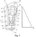
- a prosthesis socket 1 is shown in a plan view, which in the exemplary embodiment shown is designed as a thigh socket for receiving a thigh stump.
- the prosthesis socket 1 has at its distal end an end piece 2, which forms the distal end of a receiving space for a stump.
- the distal end piece 2 is opposite a proximal opening 3.
- the prosthesis socket 1 is essentially funnel-shaped, encloses the stump (not shown) substantially completely and forms a lower end, so that a stump, possibly together with a liner pulled over the stump, can only be inserted as far as the distal end piece 2.
- connection means 4 for further prosthetic components is arranged or fastened on the distal end piece.
- the connection means 4 are, for example, pyramid adapters, form-fitting receptacles, screw receptacles, bolts or other devices with which further prosthesis components can be attached to the prosthesis socket 1.
- a prosthetic knee joint is fixed to the distal end piece 2 via the connecting means 4.
- a prosthetic foot or a lower leg tube is attached to the connecting means 4 as a further prosthetic component, and in the configuration as a forearm shaft a prosthetic hand.
- the end piece 2 can be designed as a flat plate or as a cup-shaped receptacle and closure of the prosthesis socket 1. In addition to a preferably dimensionally stable design of the end piece 2, for example made of metal, plastic or the like, the end piece 2 can also be made flexible.
- the end piece 2 is adjoined in the proximal direction by support elements 5, 6, 7, 8, which are either formed in one piece with the end piece 2 or are made separately and fastened thereon.
- the support elements 5, 6, 7, 8 are arranged such that they form a receiving space between them, in which the stump (not shown) can be inserted through the insertion opening 3.
- the support elements 5, 6, 7, 8 completely surround the stump.
- the support elements 5, 6, 7, 8 Due to the segmented configuration of the support elements 5, 6, 7, 8 and either a movable mounting on the end piece 2 or an inherent elasticity, for example due to the choice of material or a material weakening in the area of the end piece 2, it is possible to support the support elements 5, 6 , 7, 8 to move away from each other and towards each other in order to widen the prosthesis socket or to reduce the insertion opening 3 and the receiving space.
- the inner circumference of the prosthesis socket 1 is changed by the displacement of the support elements as a result of the activation or deactivation of an actuator.
- a further support element 8 is fixed with a hinge to the end piece 2 and is used for improved frontal support. It is possible that the lateral support element 6 is attached to the further support element 8.
- the tensioning devices or tensioning elements 11, 12, 13 are designed in the exemplary embodiment shown as cords, cables or ropes, it is also possible that instead of the tensioning devices 11, 12, 13 shown in rope form, they are also in the form of a belt or rod, chain, perforated or another form of traction means is formed. It is essential that the tensioning device is suitable for displacing the support devices towards one another, that is, for applying tensile forces, with mainly circular forces acting due to the flexible and preferably inelastic design of the tensioning devices 11, 12, 13. By shifting the support elements 5, 6, 7, 8 towards each other, the inner circumference of the prosthesis socket is reduced.
- the tensioning devices 11, 12, 13 are guided in eyelets on the mutually opposite edges of the support elements 5, 6 and arranged in the manner of a shoe lacing.
- a total of three mutually independent clamping devices 11, 12, 13 are arranged on the prosthesis socket 1, which are arranged offset to one another in the proximal-distal direction, which makes it possible for different pressures to be exerted on the stump at different heights.
- the tensioning devices 11, 12, 13 can be tensioned via an actuator, in the exemplary embodiment a motor, for this purpose the tensioning devices are wound on a reel which is coupled to the motor, for example via a transmission, so that relatively small motors with high speeds can be used , which saves space and weight. If the motors (not shown) are activated, the respective tensioning device 11, 12, 13 is wound up, the support devices 5, 6, 7, 8 are moved towards one another and the prosthesis socket 1 closes around the stump.
- a control device 40 is also arranged in the prosthesis socket 1, via which the actuators or motors or the actuator or the motor, if only one actuator or motor is used, are controlled.
- the control device 40 is connected to the actuators.
- the control device 40 is connected to a switch 45, via which the opening or closing of the prosthesis socket 1 can be switched on.
- a contact sensor 30 is arranged in the distal region of the receiving space, in the exemplary embodiment shown in the distal end region of the receiving space. If the contact sensor 30 is touched, a signal is sent to the control device 40, so that the actuator / motor or actuators / motors are automatically activated in order to close the clamping devices 11, 12, 13.
- the contact sensor 30 can also be designed as a simple switch.
- Pressure sensors 31, 32, 33 are arranged along at least one support element 5, via which the contact pressure of the support elements 5, 6, 7, 8 is monitored. If preset pressures are reached, the respective actuator is deactivated via the control device 40.
- a pressure distribution is advantageously set, as shown in the diagram on the right in Figure 1 is shown, in which there is an increased pressure in the distal region, which decreases in the proximal direction.
- an inertial sensor 35 can be attached to the prosthesis socket 1.
- the inertial sensor 35 detects the position of the prosthesis socket 1 in space. In this way, different information can be obtained, for example relating to the activity level, so that depending on the activity detected in each case, the contact pressure can be adjusted by changing the inner circumference by opening or closing the clamping devices 11, 12, 13.
- inertial sensor 35 or inertial angle sensor which detects the orientation to a fixed reference variable, for example the gravitational force
- position sensors, acceleration sensors or other sensors can be arranged on the prosthesis socket 1 and coupled to the control unit 40 in order to provide information about the current activities gain.
- a time switch device can also be stored in the control unit 40, via which a time-controlled tensioning or relaxation of the tensioning devices 11, 12, 13 can be initiated.
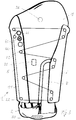
- FIG. 2 shows a variant of the invention in a schematic representation in the open state.
- the same reference numerals designate the same components.
- the two lateral support elements 5, 6 are unfolded medially-laterally, so that a widened insertion opening 3 results.
- a single tensioning device 11 in the form of a cable or a cord is arranged on the outer circumference of the prosthesis socket 1.
- the continuous tensioning device 11 is guided along deflection rollers 22, which are arranged at different levels or heights in the proximal-distal direction.
- the tensioning device 11 is meandering around the deflection rollers 22, the tensioning device 11 being rolled up on a roller 46 when an actuator 41 in the form of a motor is driven in a corresponding direction of rotation.
- a motor current sensor 44 is assigned to the motor 41 and measures the applied motor current. The motor current makes it possible to detect the motor torque and thus the force with which the tensioning device 11 is tensioned.
- the clamping force 11 of the clamping device 11 allows conclusions to be drawn as to the applied contact pressure of the support elements 5, 6, 7, 8 on the stump.
- a pressure sensor 31 is arranged on the inside of the frontal support element 7 in order to be able to transmit a further measured value to the control unit 40 (not shown).
- a rear support element which is also arranged overlapping with the medial and lateral support elements 5, 6 on the end piece 2, so that the stump (not shown) is completely enclosed.
- the distal contact sensor 30 is arranged on the bottom of the receiving space on the end piece 2.
- the support elements 5, 6, 7, 8 are biased toward the outside or are designed to be elastic, so that after the tensioning device 11 is relaxed by unwinding the tensioning device 11 from the roller 46 of the prosthesis socket 1.
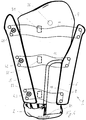
- FIG 3 shows the prosthesis socket 1 according to Figure 2 in a closed state.
- a stump (not shown) has been introduced into the receiving space through the insertion opening 3 and has activated the contact sensor 30.
- the motor 41 was put into operation on the basis of the activation signal from the control unit 40 (not shown).
- the tensioning device 11 was wound up on the roll 46 until the motor current sensor 44 or the pressure sensor 31 transmits a signal to the control unit 40 until the desired or preset limit pressure is reached.
- the control unit 40 has switched off the motor 41 and holds the tensioning device 11 in the tensioned state.
- the tensioning device 11 is guided vertically along the medial support element 4 in the proximal-distal direction, crosses frontally in the lower region of the support elements 5, 6, 7, 8 and is deflected by deflection rollers 22, so that a zigzag-like arrangement or a zigzag-like course between the medial support element 5 and the lateral support element 6 results. In the proximal end region, the tensioning device 11 again crosses frontally and is coupled to the roller 46 and is wound up there. In addition to a permanent application of a holding current to the motor 41, it is possible and provided that a mechanical locking device is assigned to the tensioning device 11, so that the motor 41 can be switched off. The mechanical locking device can then be unlocked for unlocking and the motor 41 can be activated in a reverse direction of rotation in order to open the prosthesis socket 1.
- a variant of the embodiment according to Figure 3 is in the Figure 4 shown.
- three motors 41, 43 are fixed to the prosthesis socket 1 at different heights in the proximal-distal direction.
- Each motor 1 is assigned to a tensioning device 11, 12, 13.
- pressure sensors 31, 32, 33 are arranged on the inside of the prosthesis socket 1 in the receiving space, in the exemplary embodiment shown on the frontal support element 7.
- the pressure sensors 31, 32, 33 can also be on another support element , 5, 6, 7, 8, several sensors 31, 32, 33 can also be arranged on each support element 5, 6, 7 8, sensors can also be arranged at different heights on different support elements.
- All motors 41, 42, 43 are connected to the control unit 40, not shown. If the sensor 30 or contact switch 30 is activated, the motors 41, 42, 43 are activated in such a way that the tensioning devices 11, 12, 13 are wound up, for example on a motor shaft.
- FIG. 6 shows a schematic representation of the engine control.
- the control unit 40 is connected to the motor 41 or the motors.
- the distal shaft switch 30, the manual switch 45, the pressure sensor (s) 31 and the inertial sensor 35 are also connected to the control unit 40. Additional sensors or switches can also be connected to the control unit 40. Based on the information from the sensors or commands from the switches, the control unit 40 activates the motor and tensions or relaxes the respectively assigned tensioning device.
- the prosthesis socket according to the invention enables automatic opening and closing by appropriately activating or deactivating one actuator or several actuators which are connected to one or more tensioning devices, for example a lacing system or several lacing systems.
- the actuators can also actuate and shift other active elements such as levers, gears and racks, sliders, spindles, expansion wedges, rings or clasps in order to effect an inner circumference change on the basis of sensor data.
- the prosthesis socket can also be formed with only one one-piece shaft wall, which has a slot or is wound spirally like a torch.
- the prosthesis socket can be opened or closed by moving a ring or a clip along the longitudinal extension of the socket.
- Other measures for changing the inner circumference have already been described above.
- the prosthesis socket has the advantage, among other things, that the prosthesis socket can be correctly adjusted to the stump even in the event of fluctuations in the stump volume or with different stumps. It is therefore no longer necessary to provide an individually molded prosthetic stump.
- the prosthesis socket In the basic state, the prosthesis socket is open, which means that the support elements are sculpted on.
- the distal shaft switch is activated, whereby the distal switch can be designed as a contact switch, pressure switch, mechanical switch or proximity switch, the actuator or the actuators are activated until the preset normal contact pressure of the shaft wall or the support elements on the stump is reached.
- the usual activities can be carried out, for example walking a prosthesis of the lower extremity or climbing stairs.
- one or more actuators are activated via the control unit in order to reduce the inner circumference and, if necessary, to retension the tensioning device or devices.
- the change or tensioning process continues until a preset contact pressure is reached that appears suitable for the detected loading mode, for example during sports.
- the contact pressure is reduced by loosening the clamping devices, reducing the volume, activating or deactivating the magnet, and shape memory alloys activated or deactivated or other changes are made until normal pressure is reached again.
- the prosthesis socket opens due to the elasticities inherent in the support elements or the socket wall or a separate restoring device, for example a spring, which loads the prosthesis socket with a force away from the stump.
- the actuator or the actuators can start the tensioning devices or other means based on the normal mode Relax the change in the inner circumference so that the prosthesis socket is in a relaxation mode with a lower contact pressure due to the enlarged inner circumference. This can be done, for example, while sitting or lying down.
- Such conditions can be detected via acceleration sensors, position sensors and inertial sensors. If a movement recording is detected, for example via acceleration sensors, the motors tension or the motor tensions the tensioning device or the tensioning devices again or the pump changes the volume in the inflatable cushion until the normal pressure is reached.
- the contact pressures can again be determined directly via pressure sensors or indirectly via motor current sensors or other sensors.
- a manual switch may be actuated, which relaxes the tensioning device or tensioning devices to the maximum or activates the actuator for a maximum increase in the inner circumference. If the actuators / motors or the actuator / motor should or should fail, a mechanical unlocking device can be provided, by means of which the tensioning device can be completely relaxed or the inner circumference can be enlarged in order to enable the prosthetic socket to be exited.
- the prosthesis socket is advantageously closed as soon as the distal shaft sensor or socket switch indicates that the stump or limb has been inserted completely.
- the shaft can be closed via a separate locking button, a magnetic switch, a smartphone, a tablet, a remote control or the like, for this purpose the control unit is connected to a receiver module or a corresponding contact with the switch.
- Voice control can also be provided to open or close the prosthesis socket.
- a massage effect can be provided for the stump taken up, which can be pleasant for the prosthesis user.
- the tensioning device can be tightened or relaxed as part of a time program in order to avoid undesirable pressure points and damage to the stump tissue.
- the sensors for recording the respective activities can be arranged both on the prosthesis socket and on the connected prosthesis device, the sensors located there, for example inertial angle sensors, acceleration sensors, gyroscopes or angle sensors, can be used to adapt the inner circumference, e.g. by tensioning or relaxing tensioning devices.
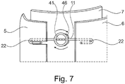
- Figure 7 shows a detailed view of a schematic representation of a prosthesis socket 1 with three support elements 5, 6, 7, two of which are arranged to overlap each other.
- the support elements 5, 6 are arranged such that they form an inner circumference of the prosthesis socket that is smaller than the outer circumference of a stump to be accommodated or a stump to be accommodated with a prosthesis liner. This can be brought about by a corresponding preforming or else by a prestressing force which causes the support elements 5, 6 to be displaced in the direction of the stump.
- This can be, for example, a spring force which supports the support elements 5, 6 which are articulated on an end piece Direction shifted or preloaded on the stump, not shown.
- An actuator 41 in the form of a motor is arranged on the third support element 7 and is coupled to a roller 46 to which a tensioning element 11 in the form of a cable is fastened. Also arranged on the support element 7, to which the actuator 41 is attached, are a pair of deflection elements 22, which are positioned on opposite sides of the roller 46.
- the cable 11 is fastened to the roller 46 and guided around the deflection elements or deflection rollers 52, the free ends of the cable 11 which are not fastened to the roller 46 being guided back in the direction of the roller 46.
- the guidance of the cable 11 is thus U-shaped.
- One free end each is attached to the support element 5, 6, which covers the respective deflection roller 22. If the prosthesis socket consists of only two support elements, that is to say a gap or a slot is formed between a shaft wall and is covered by the second support element 7, the free ends are each fixed in the region of the mutually opposite edges on both sides of the roller 46.
- Figure 8 shows the structure of the spreader according to Figure 7 when not open.
- the cable 11 is guided in opposite directions around the two deflection rollers 22 arranged at a distance from one another and back again to the edges of the two displaceable support elements 5, 6. There, the free ends of the cable 11 are each attached to an attachment point.
- the cable 11 is unrolled to a maximum, which means that the support elements 5, 6 are moved towards one another to a maximum and this results in a minimal inner circumference of the prosthesis socket. If the inner circumference is now to be enlarged, the actuator 41 is activated in the form of a motor, which in the Figure 9 is shown.
- the roller 46 By activating the actuator 41, the roller 46 is set in rotation, the cable 11 is rolled up and the fastening points with the free ends of the cable 11 are pulled in the direction of the respective deflection roller 22.
- the gap or distance between the two support elements 5, 6 or the gap in a prosthesis socket wall increases, as a result of which the inner circumference is enlarged and entry into the prosthesis socket is facilitated or exiting is facilitated or made possible.
- the actuator 41 initiates a reverse movement, and the cable 11 is unwound and the two support elements 5, 6 move in the opposite direction of the arrow Figure 9 towards each other again. This reduces the inner circumference, increases the pressure on the stump located inside the prosthesis socket and improves the fit.
- the exemplary embodiments described above also function and are operated without sensors and without a control device, the actuator 41 then being actuated either by motor or manually.
- the manual or motorized opening without sensors and control device by activating a motor or by manually actuating an actuator, for example a rack, a slide, a thread, a roller, an adjustment of an expansion element, for example a ring, a clip or the like, enables to increase the inner circumference.
- the resetting is advantageously carried out by an elastic restoring force which is impressed on the opened prosthesis socket.
Landscapes
- Health & Medical Sciences (AREA)
- Transplantation (AREA)
- Biomedical Technology (AREA)
- Cardiology (AREA)
- Oral & Maxillofacial Surgery (AREA)
- Engineering & Computer Science (AREA)
- Heart & Thoracic Surgery (AREA)
- Vascular Medicine (AREA)
- Life Sciences & Earth Sciences (AREA)
- Animal Behavior & Ethology (AREA)
- General Health & Medical Sciences (AREA)
- Public Health (AREA)
- Veterinary Medicine (AREA)
- Orthopedic Medicine & Surgery (AREA)
- Prostheses (AREA)
Description
Die Erfindung betrifft einen Prothesenschaft mit einer proximalen Einführöffnung und einem einen Stumpf zumindest teilweise umgebenden Innenumfang, zumindest einer Anschlussvorrichtung für eine Prothesenkomponente, die an dem Prothesenschaft befestigbar ist und zumindest einem Aktuator, über den der Innenumfang des Prothesenschaftes veränderbar ist. Die Erfindung betrifft ebenfalls ein Verfahren zur Steuerung einer Anpassung eines Innenumfanges eines solchen Prothesenschaftes.The invention relates to a prosthesis socket with a proximal insertion opening and an inner circumference at least partially surrounding a stump, at least one connecting device for a prosthesis component which can be fastened to the prosthesis socket and at least one actuator via which the inner circumference of the prosthesis socket can be changed. The invention also relates to a method for controlling an adaptation of an inner circumference of such a prosthesis socket.
Prothesenschäfte dienen zur Aufnahme von Stümpfen, beispielsweise von Amputationsstümpfen und stellen sicher, dass weitere Prothesenkomponenten sicher an der verbliebenen Gliedmaße gehalten werden. Um ein sicheres Festlegen des Prothesenschaftes an dem Stumpf zu gewährleisten, sind verschiedene Befestigungskonzepte entwickelt worden. Ein Konzept sieht eine im Wesentlichen geschlossene, mit einer Einführöffnung versehene, formstabile Hülle vor, in die der mit einem Prothesenliner versehene Stumpf eingeführt wird. Der Prothesenschaft hält dann über Unterdruck an dem Liner.Prosthetic stems are used to hold stumps, such as amputation stumps, and ensure that other prosthetic components are held securely on the remaining limb. Various fastening concepts have been developed to ensure that the prosthesis socket is securely attached to the stump. One concept provides for an essentially closed, dimensionally stable shell with an insertion opening, into which the stump provided with a prosthesis liner is inserted. The prosthesis socket then holds the liner via negative pressure.
Eine weitere Möglichkeit besteht darin, einen Prothesenliner mit einer mechanischen Verriegelungseinrichtung auszustatten, beispielsweise einem Stift, der in eine Aufnahme innerhalb des Prothesenschaftes eingeführt und dort formschlüssig verriegelt wird. Beiden Befestigungskonzepten ist gemeinsam, dass die Innenkontur des Prothesenschaftes möglichst genau der Außenkontur des Stumpfes mit einer Zugabe für den Liner entsprechen sollte. Um dies zu erreichen, wird ein Stumpfabdruck genommen, ein Positivmodel des Stumpfes angefertigt und anhand dieses Models ein individueller Prothesenschaft aus in der Regel faserverstärktem Kunststoff gefertigt.Another possibility is to equip a prosthesis liner with a mechanical locking device, for example a pin, which is inserted into a receptacle within the prosthesis socket and locked there in a form-fitting manner. Both fastening concepts have in common that the inner contour of the prosthesis socket should correspond as closely as possible to the outer contour of the stump with an addition for the liner. In order to achieve this, a die impression is taken, a positive model of the die is made and an individual prosthesis socket made of usually fiber-reinforced plastic is made using this model.
Neben solch in Umfangsrichtung geschlossenen Schäften sind Prothesenschäfte bekannt, die in Radialrichtung verstellbar ausgeführt sind. Die
Die
Die
Die
Die
Die
Die
Die Festlegung des Prothesenschaftes an einem Stumpf, gegebenenfalls an einem Liner, kann schwierig sein, insbesondere für mehrfach versorgte Patienten, die hinsichtlich ihrer manuellen Fertigkeiten eingeschränkt sind.Fixing the prosthetic socket on a stump, possibly on a liner, can be difficult, especially for patients with multiple care who are limited in their manual skills.
Aufgabe der vorliegenden Erfindung ist es, einen Prothesenschaft und ein Verfahren bereitzustellen, die ein einfaches Anlegen ermöglichen.The object of the present invention is to provide a prosthesis socket and a method which enable simple fitting.
Erfindungsgemäß wird diese Aufgabe durch einen Prothesenschaft mit den Merkmalen des Hauptanspruches sowie ein Verfahren mit den Merkmalen des nebengeordneten Anspruchs gelöst. Vorteilhafte Ausgestaltungen und Weiterbildungen der Erfindung sind in den Unteransprüchen, der Beschreibung sowie den Figuren offenbart.According to the invention, this object is achieved by a prosthesis socket with the features of the main claim and a method with the features of the independent claim. Advantageous refinements and developments of the invention are disclosed in the subclaims, the description and the figures.
Der Prothesenschaft mit einer proximalen Einführöffnung und einem einen Stumpf zumindest teilweise umgebenen Innenumfang, zumindest einer Anschlussvorrichtung für eine Prothesenkomponente, die an dem Prothesenschaft befestigbar ist und zumindest einem Aktuator, über den der Innenumfang des Prothesenschaftes veränderbar ist, sieht zumindest einen als Inertialsensor ausgebildeten Sensor vor, der mit einer Steuerungseinrichtung gekoppelt ist, wobei die Steuerungseinrichtung mit dem Aktuator verbunden ist und diesen in Abhängigkeit von den empfangenen Sensorsignalen aktiviert oder deaktiviert.The prosthesis socket with a proximal insertion opening and an inner periphery at least partially surrounding a stump, at least one connection device for a prosthesis component that can be fastened to the prosthesis socket and at least one actuator, via which the inner periphery of the prosthesis socket can be changed, provides at least one sensor designed as an inertial sensor , which is coupled to a control device, the control device being connected to the actuator and activating or deactivating it as a function of the received sensor signals.
Durch die Kopplung eines Aktuators zur Veränderung des Innenumfanges eines Prothesenschaftes mit einem Sensor über eine Steuerungseinrichtung dergestalt, dass der Aktuator in Abhängigkeit von empfangenen Sensorsignalen aktiviert oder deaktiviert wird, ermöglicht ein automatisches Spannen oder Entspannen des Prothesenschaftes beziehungsweise der Anlagekraft des Prothesenschaftes an den Stumpf, so dass beispielsweise der Prothesenschaft geöffnet oder geschlossen werden kann, um ein Aussteigen und Einsteigen zu erleichtern und ein automatischen Anlegen zu ermöglichen. Darüber hinaus ist es möglich, automatisch oder auch willentlich Volumenschwankungen innerhalb des Stumpfes auszugleichen, indem beispielsweise bei einem sich vergrößernden Stumpfvolumen während der Tragedauer der Innenumfang vergrößert wird, um den Anpressdruck zu verringern. Ebenso ist es möglich, den Innenumfang bei einer Detektion von besonderen Belastungen, beispielsweise beim Sport, zu verringern, um eine festere Anlage des Prothesenschaftes an den Stumpf bereitzustellen. Darüber hinaus können periodische Veränderungen des Innenumfanges vorgenommen werden, um einen Massageeffekt zu erzielen. Auch kann bei der Detektion von Ruhephasen, beispielsweise während des Sitzens, automatisch der Innenumfang vergrößert werden. Das Öffnen und Schließen des Prothesenschaftes kann somit selbstständig erfolgen.By coupling an actuator to change the inner circumference of a prosthesis socket with a sensor via a control device such that the actuator is activated or deactivated depending on received sensor signals, the prosthesis socket or the contact force of the prosthesis socket on the stump can be automatically tensioned or relaxed, so that, for example, the prosthesis socket can be opened or closed to make it easier to get in and out and to enable automatic donning. In addition, it is possible to automatically or deliberately compensate for volume fluctuations within the stump, for example by increasing the inner circumference in the case of an increasing stump volume during the period of wear, in order to reduce the contact pressure. It is also possible to reduce the inner circumference when detecting special loads, for example during sports, in order to provide the prosthesis socket against the stump more firmly. In addition, periodic changes in the inner circumference can be made to to achieve a massage effect. The inner circumference can also be automatically increased when detection of resting phases, for example while sitting. The prosthesis socket can thus be opened and closed independently.
Der Aktuator kann als Antrieb für eine Pumpe, ein Verschiebelement, einen Hebel, eine Wickeleinrichtung für Zugmittel, ein Spreizelement, ein Getriebe, als Antrieb zur Aktivierung einer Formgedächtnislegierung oder eine elektroaktiven Polymers oder als schaltbarer Magnet ausgebildet sein. Insbesondere kann der Aktuator als Motor ausgebildet sein und beispielsweise eine Spanneinrichtung antreiben, die beispielsweise ein Zugmittel wie Gurt, Seil, Band, Kabel oder Litze aufweist und dessen effektive Länge vergrößert oder verkleinert und dadurch den Prothesenschaft in seinem Innenumfang verändert. Grundsätzlich ist es auch vorgesehen, das der Aktuator manuell betrieben oder manuell angesteuert werden kann, beispielsweise durch einen Schalter, so dass keine Steuereinrichtung und kein Sensor vorhanden sein müssen. Der zumindest eine Aktuator kann auch eine Pumpe antreiben, über die ein veränderbares Volumen, das an oder in dem Prothesenschaft angeordnet oder ausgebildet ist, verändert werden. So kann beispielsweise bei einem geschlossenen Prothesenschaft ein auf der Innenseite angeordnetes Volumen vorhanden sein, das mit Druckluft oder einem Hydraulikfluid, das an einem außenseitigen Reservoir angeordnet ist, gefüllt werden kann, um so den Innenumfang zu verändern. Dazu benötigt der Prothesenschaft ein Widerlager, das beispielsweise durch den geschlossenen Querschnitt oder aber durch eine rigide Spanneinrichtung oder Begrenzungseinrichtung, beispielsweise ein festeingestelltes Zugmittel bereitgestellt wird. Ebenso ist es möglich, dass über eine Volumenveränderung bei einem mehrteiligen Prothesenschaft mit mehreren Stützelementen, die relativ zueinander verlagerbar sind, eine Innenumfangsveränderung realisiert wird. Dies kann entweder durch Aufbringen einer Verlagerungskraft auf die Stützelemente durch das sich verändernde Volumen erfolgen, beispielsweise durch Aufblasen, oder durch ein Befüllen eines gegen ein Widerlager drückendes Volumen oder aber durch innenseitige Volumenvergrößerung. Ebenfalls ist es möglich, das Volumen mechanisch zu vergrößern, beispielsweise durch Aufstellen von gelenkig gelagerten Hebeln oder Fasern, die sich bei Verlagerung beispielsweise eines Schiebers aufstellen, gegen eine Volumenwand drücken und dadurch eine Volumenveränderung des Volumens bewirken. Ebenso ist es möglich, dass ein um den Prothesenschaft herum gelegter Ring längsverschieblich gelagert ist. Durch eine konische Ausgestaltung des Prothesenschaftes oder eine konische Gestaltung einer Ringführung an der Außenseite ist es möglich, durch eine Längsverschiebung Stützelemente, die Teil eines mehrteiligen Prothesenschaftes sind, aufeinander zu zu verlagern oder voneinander weg zu bewegen. Dadurch kann eine nach innen gerichtete Verschwenkung oder außen gerichtete Aufspreizbewegung verwirklicht werden. Neben einer mehrteiligen Ausgestaltung des Prothesenschaftes ist es auch möglich, diesen einteilig auszubilden und mit einem Schlitz zu versehen, gegebenenfalls mit überlappenden Seitenkanten, um ein vollständiges Umfassen des Prothesenstumpfes zu ermöglichen und gleichzeitig eine Umfangsveränderung zu ermöglichen. Der Prothesenschaft ist dann spiralförmig ausgebildet, eine Veränderung des Innenumfanges wird dadurch erreicht, dass der Wicklungswinkel oder Überdeckungswinkel der beiden Seitenkanten verändert wird.The actuator can be designed as a drive for a pump, a displacement element, a lever, a winding device for traction means, a spreading element, a gear, as a drive for activating a shape memory alloy or an electroactive polymer or as a switchable magnet. In particular, the actuator can be designed as a motor and, for example, drive a tensioning device which, for example, has a traction means such as a belt, rope, band, cable or strand and increases or decreases its effective length and thereby changes the inside circumference of the prosthesis socket. In principle, it is also provided that the actuator can be operated manually or controlled manually, for example by means of a switch, so that no control device and no sensor have to be present. The at least one actuator can also drive a pump, via which a changeable volume, which is arranged or formed on or in the prosthesis socket, can be changed. For example, in the case of a closed prosthesis socket, there can be a volume arranged on the inside, which can be filled with compressed air or a hydraulic fluid which is arranged on an outside reservoir, so as to change the inner circumference. For this purpose, the prosthesis socket requires an abutment, which is provided, for example, by the closed cross section or by a rigid tensioning device or limiting device, for example a fixed traction device. It is also possible for a change in volume in the case of a multi-part prosthesis socket with a plurality of support elements which can be displaced relative to one another to implement an inner circumference change. This can be done either by applying a displacement force to the support elements due to the changing volume, for example by inflation, or by filling a volume pressing against an abutment or by increasing the volume on the inside. It is also possible to increase the volume mechanically, for example by setting it up of articulated levers or fibers that stand up when a slide is moved, for example, press against a volume wall and thereby cause a volume change in volume. It is also possible that a ring placed around the prosthesis socket is mounted to be longitudinally displaceable. Due to a conical configuration of the prosthesis socket or a conical configuration of a ring guide on the outside, it is possible, by means of a longitudinal displacement, to shift support elements which are part of a multi-part prosthesis socket towards one another or to move them away from one another. In this way, an inward pivoting or outward spreading movement can be realized. In addition to a multi-part design of the prosthesis socket, it is also possible to form it in one piece and to provide it with a slot, possibly with overlapping side edges, in order to enable the prosthesis stump to be completely encompassed and at the same time to enable a change in circumference. The prosthesis socket is then spiral-shaped, the inner circumference is changed by changing the winding angle or overlap angle of the two side edges.
Ebenso ist es möglich, dass der Aktuator als schaltbarer Magnet ausgebildet ist, über den eine entsprechende Verstellung mechanischer, magnetorheologischer oder sonstiger Komponenten erfolgen kann.It is also possible that the actuator is designed as a switchable magnet, via which a corresponding adjustment of mechanical, magnetorheological or other components can take place.
In einer Variante der Erfindung ist es vorgesehen, dass der Prothesenschaft mit einer proximalen Einführöffnung und einem einen Stumpf zumindest teilweise umgebenden Innenumfang, zumindest einer Anschlussvorrichtung für eine Prothesenkomponente, die an dem Prothesenschaft befestigt ist, zumindest einen Aktuator aufweist, über den der Innenumfang des Prothesenschaftes vergrößerbar ist. Der Aktuator kann manuell oder motorisch antreibbar oder angetrieben sein, so dass es möglich ist, eine Erweiterung des Innenumfanges des Prothesenschaftes, also das Öffnen des Prothesenschaftes, auch ohne einen Sensor durchzuführen. Die obenstehenden, zu einer Umfangsvergrößerung in Verbindung mit einem Sensor gemachten Ausführungen gelten für einen solchen Prothesenschaft entsprechend, jedoch ohne dass ein Sensor und eine Steuereinrichtung vorgesehen sein müssen. Ein motorischer Antrieb kann durch einen Schalter, eine Fernbedienung oder dergleichen von einem Prothesennutzer aktiviert oder deaktiviert werden, um den Innenumfang des Prothesenschaftes zu vergrößern. Eine manuelle Betätigung oder Betätigbarkeit des Aktuators verringert das Gewicht des Prothesenschaftes und ermöglicht eine einfache Vergrößerung des Innenumfanges durch manuelles Verstellen oder Manipulieren des Aktuators.In a variant of the invention, it is provided that the prosthesis socket with a proximal insertion opening and an inner circumference at least partially surrounding a stump, at least one connecting device for a prosthesis component, which is attached to the prosthesis socket, has at least one actuator over which the inner circumference of the prosthesis socket can be enlarged. The actuator can be driven or driven manually or by a motor, so that it is possible to expand the inner circumference of the prosthesis socket, that is to say to open the prosthesis socket, even without a sensor. The above explanations made for an increase in circumference in connection with a sensor apply correspondingly to such a prosthesis socket, but without a sensor and a control device being provided have to. A motor drive can be activated or deactivated by a switch, a remote control or the like by a prosthesis user in order to enlarge the inner circumference of the prosthesis socket. A manual actuation or operability of the actuator reduces the weight of the prosthesis socket and enables a simple enlargement of the inner circumference by manually adjusting or manipulating the actuator.
Es ist insbesondere vorgesehen, dass ein solcher Prothesenschaft mit einem Aktuator, der den Innenumfang vergrößert, bei einem Prothesenschaft eingesetzt wird, der über eine elastische Rückstellkraft an dem Stumpf hält. Die elastische Rückstellkraft wird durch die Prothesenschaftwand selbst oder durch die Stützelemente ausgebildet. Ebenso kann durch eine elastische Lagerung des Stützelementes oder der Prothesenschaftwand die elastische Rückstellkraft in Richtung auf den Stumpf, also in Richtung auf einen sich verkleinernden Innenumfang aufgebracht werden. Der gewünschte Innendurchmesser wird durch den Grand der Öffnung des Prothesenschaftes durch den Aktuator eingestellt und erzielt. Das Öffnen kann sowohl manuell als auch manuell gesteuert motorisch erfolgen. Ebenso ist es möglich, dass das Öffnen automatisch nach der Detektion entsprechender Sensorwerte wie Lage, Position im Schaft, Position des Schaftes, Druck, Zeitdauer eines Druckes, Druckveränderungen, Sauerstoffsättigung, Durchblutung, Temperatur oder dergleichen ausgeübt wird. Nach dem Öffnen, insbesondere nach einem vollständigen Öffnen, kann der Prothesenschaft über den Stumpf gezogen oder der Stumpf in den Prothesenschaft eingesetzt werden. Durch Nachlassen der zum Öffnen aufgebrachten Kraft, beispielsweise einer entsprechend umgelenkten Zugkraft, durch ein Spreizelement, das an einem Spalt entlang gefahren wird oder durch einen Ring, der entlang eines konisch geformten Schaftes verfahren wird, wird die auf den Stumpf aufgebrachte Anlagekraft eingestellt und der Schaft an den Stumpf angepasst. Eine aktive Betätigung erfolgt somit nur in Richtung des Öffnens des Schaftes, die Rückstellung in Richtung auf den Stumpf und damit eine Verringerung des Innenumfanges erfolgt passiv durch eine elastische Ausgestaltung oder Lagerung der Stützelemente oder der Prothesenschaftwand.In particular, it is provided that such a prosthesis socket with an actuator that increases the inner circumference is used in a prosthesis socket that holds on the stump via an elastic restoring force. The elastic restoring force is generated by the prosthesis socket wall itself or by the support elements. Likewise, the elastic restoring force can be applied in the direction of the stump, that is to say in the direction of a shrinking inner circumference, by an elastic mounting of the support element or the prosthesis socket wall. The desired inner diameter is set and achieved by the size of the opening of the prosthesis socket by the actuator. The opening can be done both manually and manually controlled by motor. It is also possible that the opening is carried out automatically after the detection of corresponding sensor values such as position, position in the shaft, position of the shaft, pressure, duration of a pressure, pressure changes, oxygen saturation, blood flow, temperature or the like. After opening, in particular after fully opening, the prosthesis socket can be pulled over the stump or the stump inserted into the prosthesis socket. By releasing the force applied for opening, for example a correspondingly deflected pulling force, by means of a spreading element which is moved along a gap or by a ring which is moved along a conically shaped shaft, the contact force applied to the stump is adjusted and the shaft adapted to the stump. Active actuation thus only takes place in the direction of the opening of the socket, the provision in the direction of the stump and thus a reduction in the inner circumference takes place passively through an elastic configuration or mounting of the support elements or the prosthesis socket wall.
Der Prothesenschaft ist insbesondere mehrteilig, zumindest mit zwei Stützelementen ausgebildet, die den Stumpf zwischen sich aufnehmen, wobei die Stützelemente den Stumpf entweder vollständig umgeben oder zumindest teilweise so umfassen, dass dieser fest in dem Prothesenschaft aufgenommen ist. Die Stützelemente können einander überlappend ausgebildet sein.The prosthesis socket is in particular in several parts, at least formed with two support elements which receive the stump between them, the support elements either completely surrounding the stump or at least partially encompassing it so that it is firmly accommodated in the prosthesis socket. The support elements can be designed to overlap one another.
Zumindest eine Spanneinrichtung kann an dem Prothesenschaft angeordnet sein, um dessen Innenumfang zu verändern. Die Spanneinrichtung kann als Zugmittel, pneumatisch oder hydraulisch angetriebene Spreiz- oder Spannmittel, als längsverschiebliches Spreiz- oder Schließelement, als verfahrbarer Ring, als Kippelement oder als vertretbares Betätigungselement ausgebildet sein. Das jeweilige Spannmittel wird durch den Aktuator, gegebenenfalls unter Zwischenschaltung von Getriebe, Kraftübertragungseinrichtung oder dergleichen aktiviert oder deaktiviert.At least one tensioning device can be arranged on the prosthesis socket in order to change its inner circumference. The tensioning device can be designed as a traction means, pneumatically or hydraulically driven expansion or tensioning means, as a longitudinally displaceable expansion or closing element, as a movable ring, as a tilting element or as an acceptable actuating element. The respective clamping device is activated or deactivated by the actuator, possibly with the interposition of a gear, power transmission device or the like.
Der Aktuator, z.B. als manueller oder motorischer Antrieb einer Spanneinrichtung, erleichtert das Anziehen des Prothesenschaftes ungemein. Es müssen keine aufwändigen Verschnürungen, Betätigungen von Spanneinrichtungen, Verriegelungen von mechanischen Befestigungseinrichtungen oder dergleichen von Hand vorgenommen werden. Vielmehr wird bei einem motorischen Aktuator der Innenumfang, z.B. über die Spanneinrichtung oder das veränderbare Volumen oder die Spreizeinrichtung auf die gewünschte Spannung eingestellt, ohne dass manuelle Kraft aufgewendet werden müsste.The actuator, e.g. as a manual or motorized drive for a clamping device, it makes it much easier to tighten the prosthesis socket. No elaborate lacing, actuation of tensioning devices, locking of mechanical fastening devices or the like have to be carried out by hand. Rather, the inner circumference of a motor actuator, e.g. adjusted to the desired tension via the tensioning device or the variable volume or the spreading device, without the need for manual force.
Die zumindest eine Spanneinrichtung kann als Gurt, Seil, Band, Kabel oder Litze ausgebildet sein oder ein solches Spannelement aufweisen. Grundsätzlich sind alle zugkraftübertragenden Spannelemente sinnvoll einsetzbar, auch druckstarre Spanneinrichtungen oder Spannelemente wie Stäbe, Spangen oder Ringe. Flexible Spanneinrichtungen haben den Vorteil, dass sie sich an verändernde Umfänge leichter anpassen lassen und insgesamt einfacher handhabbar sind. Neben flexiblen Spanneinrichtungen, die vorteilhafterweise unelastisch sind, können auch Zahnriemen, Lochriemen oder Ketten als Spanneinrichtungen oder Spannelemente eingesetzt werden.The at least one tensioning device can be designed as a belt, rope, band, cable or strand or have such a tensioning element. Basically, all tension-transmitting tensioning elements can be used sensibly, including pressure-rigid tensioning devices or tensioning elements such as rods, clips or rings. Flexible clamping devices have the advantage that they are easier to adapt to changing sizes and are easier to handle overall. In addition to flexible tensioning devices, which are advantageously inelastic, toothed belts, perforated belts or chains can also be used as tensioning devices or tensioning elements.
Das zumindest eine Zugkraft übertragende Spannelement kann in Ösen, Kanälen und/oder um zumindest eine Umlenkrolle geführt sein, um beispielsweise ähnlich einem Flaschenzug eine Kraft-Weg-Übersetzung zu erreichen. Durch das Umlenken flexibler Spannelemente kann der Angriffspunkt der Spannkraft definiert werden. Durch eine Vielzahl von Umlenkrollen kann die Spannkraft vielfach verteilt und somit eine gleichmäßige Druckverteilung erreicht werden. Darüber hinaus ist es durch Umlenkrollen möglich, mit nur einer Spanneinrichtung Spannkräfte an mehreren Stellen aufzubringen, wodurch sich die Teilezahl verringert und eine erleichterte Montage verwirklichen lässt. Durch die Führung innerhalb von Kanälen, die sich innerhalb des Schaftes, beispielsweise in den Stützelementen befinden können, wird das Risiko minimiert, dass Kleidungsstücke oder andere Gegenstände zwischen der Spanneinrichtung und dem Stützelement eingeklemmt werden. Ebenso ist es möglich, durch eine Umlenkung des Spannelementes ein Aufspreizen des Prothesenschaftes zu bewirken, so dass durch Aufrollen oder Aufwickeln eine Innenumfangsvergrößerung bewirkt wird. Dazu wird das Spannelement um eine Umlenkstelle geführt, die jenseits der Befestigungsstelle liegt, an dem das freie, nicht aufgewickelte Ende befestigt ist. Dadurch wird bei einem Aufwickeln beispielsweise ein Stützelement von einem anderen weggezogen.The tension element that transmits at least one tensile force can be guided in eyelets, channels and / or around at least one deflection roller in order, for example, to achieve a force-displacement ratio similar to a pulley system. The point of application of the clamping force can be defined by deflecting flexible clamping elements. Thanks to a large number of deflection rollers, the clamping force can be distributed in many ways, thus achieving an even pressure distribution. In addition, by means of deflection rollers it is possible to apply clamping forces at several points with only one clamping device, which reduces the number of parts and facilitates assembly. By guiding within channels, which can be located inside the shaft, for example in the support elements, the risk is minimized that items of clothing or other objects are pinched between the tensioning device and the support element. It is also possible to spread the prosthesis socket by deflecting the tensioning element, so that the inner circumference is enlarged by rolling up or winding up. For this purpose, the tensioning element is guided around a deflection point, which lies beyond the fastening point, to which the free, uncoiled end is fastened. In this way, for example, one support element is pulled away from another during winding.
Es können mehrere Aktuatoren oder Spanneinrichtungen unabhängig voneinander entlang der proximal-distal-Erstreckung des Prothesenschaftes angeordnet sein, um unabhängig voneinander verschiedene Anpressdrücke auf den Stumpf durch eine Veränderung des Schaftinnenumfanges einstellen zu können.A plurality of actuators or tensioning devices can be arranged independently of one another along the proximal-distal extension of the prosthesis socket in order to be able to independently set different contact pressures on the stump by changing the inner circumference of the socket.
Die zumindest eine Spanneinrichtung wird vorteilhafterweise in Umfangsrichtung des Stumpfes wirkend angeordnet, um so einen radial wirkenden Anpressdruck des Stützelementes oder der Stützelemente auf den Stumpf zu bewirken. Bei einer einteiligen Ausgestaltung des Prothesenschafes mit der Schaftwand als Stützelement wirkt die Spanneinrichtung aufwickelnd oder die Überdeckung vergrößernd, so dass sich der Innenumfang verringert, alternativ wird bei einer gegenläufigen Bewegung der Innenumfang vergrößert, zumindest bereichsweise, so dass der Schaft gelockert oder geöffnet wird.The at least one tensioning device is advantageously arranged to act in the circumferential direction of the stump in order to bring about a radially acting contact pressure of the support element or the support elements on the stump. In the case of a one-piece design of the prosthetic sheep with the shaft wall as a supporting element, the tensioning device has a winding effect or increases the overlap, so that the inner circumference is reduced, alternatively the inner circumference is enlarged, at least in some areas, in the event of an opposing movement, so that the shaft is loosened or opened.
Die Stützelemente oder die Schaftwand selbst können elastisch ausgebildet sein, um beispielsweise bei einer Entspannung der Spanneinrichtung eine Rückstellkraft bereitzustellen, durch die es ermöglicht wird, dass sich der Prothesenschaft selbsttätig öffnet und somit der Patient leicht aus dem Prothesenschaft heraussteigen kann. Ebenso kann umgekehrt eine auf den Stumpf wirkende Vorspannung durch die Schaftwand oder die Stützelemente aufgebracht sein, die durch eine Aufspreizeinrichtung aufgehoben wird, um aus dem Schaft auszusteigen oder um den auf den Stumpf wirkenden Druck zu reduzieren. Die Stützelemente können auch elastisch an dem Endstück gelagert sein, beispielsweise gelenkig entgegen einer Federkraft. Ebenso ist es möglich, dass die Stützelemente einstückig mit dem Endstück ausgebildet sind und zum Schließen des Prothesenschaftes oder zum Anlegen des Prothesenschaftes aus einer entfernt voneinander liegenden Ausgangsposition aufeinander zu bewegt werden.The support elements or the shaft wall itself can be designed to be elastic, in order, for example, to provide a restoring force when the tensioning device is relaxed, which makes it possible for the prosthesis socket to open automatically and thus for the patient to easily get out of the prosthesis socket. Conversely, a prestress acting on the stump can also be applied by the socket wall or the support elements, which is lifted by a spreading device in order to get out of the socket or to reduce the pressure acting on the stump. The support elements can also be mounted elastically on the end piece, for example in an articulated manner against a spring force. It is also possible for the support elements to be formed in one piece with the end piece and to be moved towards one another from a starting position located at a distance from one another in order to close the prosthesis socket or to put the prosthesis socket on.
Um einen möglichst gleichmäßig auf den Stumpf wirkenden Anpressdruck der Schaftwand oder der Stützelemente zu erreichen, können diese in Umfangsrichtung einander überlappend ausgebildet sein, so dass sich zumindest im angelegten, gespannten Zustand der Prothesenschaft sich vollständig um den Stumpf herum anlegt und einen quasi geschlossenen Querschnitt ausbildet. Dadurch wird verhindert, dass Teile des Stumpfes durch einen Freiraum zwischen den Stützelementen oder in der Schaftwand herausgedrückt werden, wenn der Innenumfang verringert wird.In order to achieve a contact pressure of the socket wall or the support elements that acts as evenly as possible on the stump, these can be designed to overlap one another in the circumferential direction, so that, at least in the applied, tensioned state of the prosthesis socket, it completely lies around the stump and forms a quasi-closed cross section . This prevents parts of the stump from being pushed out by a space between the support elements or in the shaft wall when the inner circumference is reduced.
Die Schaftwand oder die Stützelemente können in Richtung voneinander weg mit einer Federkraft belastet oder im ungespannten Zustand sich in Proximalrichtung konisch erweiternd angeordnet sein, wodurch das Einsteigen in dem Schaft bzw. Anlegen des Prothesenschaftes an den Stumpf erleichtert wird. Im nicht gespannten Zustand ergibt sich somit eine trichterförmig oder konisch erweiterte Form, die das Einführen eines Stumpfes erleichtert. Erst nach Einführen des Stumpfes in den Prothesenschaft wird die Spanneinrichtung über den Aktuator gespannt oder die Spreizeinrichtung zurückgefahren, wodurch der Innenumfang verringert und z.B. die Stützelemente in Richtung aufeinander zu bewegt, entweder gegen eine Federkraft oder gegen eine elastische Rückstellkraft aufgrund der Materialverformung, so der Prothesenschaft fest an dem Stumpf anliegt.The shaft wall or the support elements can be loaded in the direction away from one another with a spring force or, in the untensioned state, can be arranged to widen conically in the proximal direction, which makes it easier to get into the shaft or to place the prosthesis shaft on the stump. In the non-tensioned state, this results in a funnel-shaped or conically expanded shape, which facilitates the insertion of a stump. Only after the stump has been inserted into the prosthesis socket is the clamping device stretched over the actuator or the spreading device retracted, as a result of which the inner circumference is reduced and, for example, the support elements are moved towards one another, either against one another Spring force or against an elastic restoring force due to the material deformation, so that the prosthesis socket is firmly against the stump.
In dem Prothesenschaft kann ein distaler Kontaktschalter oder Sensor zur Detektion eines eingeführten Stumpfes angeordnet sein. Der distale Kontaktschalter oder distale Sensor detektiert, ob der Stumpf vollständig oder zumindest bis zum einem vorgegebenen Punkt in den Prothesenschaft eingeführt ist. Sofern der Kontaktschalter oder Sensor die entsprechende Position des Stumpfes detektiert, kann automatisch der Aktuator aktiviert oder deaktiviert werden, um den Innenumfang zu verringern, wodurch sich ein selbstschließender oder selbstanlegender Prothesenschaft realisieren lässt. Der Prothesenschaft passt sich dann automatisch an die Außenkontur des Stumpfes an. Der distale Kontaktschalter oder Sensor ist vorteilhafterweise an dem Endstück angeordnet, das auch den distalen Abschluss des Einführraumes des Stumpfes bildet, kann aber auch oberhalb davon angeordnet sein.A distal contact switch or sensor for detecting an inserted stump can be arranged in the prosthesis socket. The distal contact switch or distal sensor detects whether the stump has been inserted completely or at least up to a predetermined point in the prosthesis socket. If the contact switch or sensor detects the corresponding position of the stump, the actuator can be automatically activated or deactivated in order to reduce the inner circumference, as a result of which a self-closing or self-engaging prosthesis socket can be realized. The prosthesis socket then automatically adapts to the outer contour of the stump. The distal contact switch or sensor is advantageously arranged on the end piece, which also forms the distal end of the insertion space of the stump, but can also be arranged above it.
Eine Weiterbildung der Erfindung sieht vor, dass zumindest ein Motorstromsensor oder ein innenliegender Drucksensor zur Erfassung des durch ein Stützelement auf den Stumpf aufgebrachten Druckes an der Schaftwand oder dem Stützelement angeordnet ist. Innenliegende Drucksensoren ermitteln den Anpressdruck des Stützelementes an dem Stumpf. Dazu ist es sinnvoll, den Drucksensor auf der Innenseite, also der dem Stumpf zugewandten Seite der Schaftwand oder des Stützelementes anzuordnen. Alternativ zu einer direkten Druckmessung ist es möglich und vorgesehen, über einen Motorstromsensor den Motorstrom zu messen, der proportional zu dem Motormoment ist und damit auch proportional zu der Kraft, mit welcher die Spanneinrichtung gespannt oder der Innenumfang verringert wird. Dadurch lässt sich auf den Anpressdruck des Stützelementes an den Stumpf oder den Schaftinnendruck schließen. Über den oder die Sensoren ist es möglich, eine optimierte Druckverteilung und somit einen optimierten Sitz des Prothesenschaftes an dem Stumpf zu erreichen. Insbesondere in Verbindung mit einem distalen Kontaktschalter, der die motorischen Antriebe aktiviert, ist es möglich, nach dem einfachen Einführen des Stumpfes in den Prothesenschaft ein automatisches Schließen oder Öffnen durchzuführen. Die Drucksensoren oder Motorstromsensoren erfassen den Druck am Stumpf. Überschreitet der Druck einen eingestellten Wert oder erreicht diesen, wird über eine Steuereinrichtung das weitere Spannen der Spanneinrichtung oder das Reduzieren einer Spreizung gestoppt. Somit wird stets der vorgesehene Anpressdruck bei einem Einsteigen oder Anlegen des Prothesenschaftes erreicht. Verändert sich der Schaftinnendruck, beispielsweise durch die Volumenschwankungen aufgrund längerer Belastungen oder Lagerveränderungen, wird dies über die Drucksensoren oder den Motorstromsensor erfasst. Es besteht dann die Möglichkeit, entweder die Spanneinrichtung oder die Spreizeinrichtung oder die anderen, den Innenumfang verändernden Einrichtungen entsprechend zu lösen oder anzuziehen, um eine Volumenvergrößerung oder Volumenverringerung im Stumpf auszugleichen.A further development of the invention provides that at least one motor current sensor or an internal pressure sensor for detecting the pressure applied to the stump by a support element is arranged on the shaft wall or the support element. Internal pressure sensors determine the contact pressure of the support element on the stump. For this purpose, it makes sense to arrange the pressure sensor on the inside, that is to say on the side of the shaft wall or of the support element facing the stump. As an alternative to a direct pressure measurement, it is possible and provided to use a motor current sensor to measure the motor current which is proportional to the motor torque and thus also proportional to the force with which the tensioning device is tensioned or the inner circumference is reduced. This makes it possible to infer the contact pressure of the support element against the stump or the internal pressure of the socket. Via the sensor or sensors, it is possible to achieve an optimized pressure distribution and thus an optimized fit of the prosthesis socket on the stump. Especially in connection with a distal contact switch, which activates the motor drives, it is possible to have an automatic one after simply inserting the stump into the prosthesis socket To close or open. The pressure sensors or motor current sensors record the pressure on the stump. If the pressure exceeds or reaches a set value, the further tensioning of the tensioning device or the reduction of a spread is stopped via a control device. The intended contact pressure is thus always achieved when the prosthesis socket is inserted or put on. If the internal shaft pressure changes, for example due to the volume fluctuations due to longer loads or changes in bearings, this is recorded via the pressure sensors or the motor current sensor. There is then the possibility of either loosening or tightening the tensioning device or the spreading device or the other devices that change the inner circumference, in order to compensate for an increase or decrease in volume in the stump.
Mehrere Drucksensoren können proximal-distal verteilt an der Schaftwand oder zumindest einem Stützelement angeordnet sein. Bei mehreren Motoren können mehrere Motorstromsensoren an dem Prothesenschaft angeordnet sein, so dass unabhängig voneinander über die proximal-distal-Erstreckung des Prothesenschaftes ein angepasster Druck einstellbar ist. Es können auch Druck- und Motorstromsensoren in Kombination eingesetzt werden. Es können weiterhin Sauerstoffsättigungssensoren, Durchblutungssensoren und/oder Temperatursensoren eingesetzt werden.Several pressure sensors can be arranged proximally distally on the shaft wall or at least one support element. In the case of several motors, several motor current sensors can be arranged on the prosthesis shaft, so that an adapted pressure can be set independently of one another via the proximal-distal extension of the prosthesis shaft. Pressure and motor current sensors can also be used in combination. Oxygen saturation sensors, blood circulation sensors and / or temperature sensors can also be used.
Grundsätzlich ist es möglich, die Spanneinrichtung oder auch mehrere Spanneinrichtungen über einen Motor zu spannen. Eine unabhängig voneinander einstellbare Spannung der Spanneinrichtungen erfolgt vorteilhafterweise über mehrere Motoren, die an dem Prothesenschaft angeordnet sind. Mit einem Motor können unabhängig voneinander agierende Spanneinrichtungen zwar verstellt werden, jedoch ist die ausgeübte Spannkraft der Spanneinrichtungen nicht unabhängig voneinander, zwar können über Getriebe unterschiedliche Verstellwege der Spanneinrichtungen realisiert werden, bei nur einem Motor sind diese Verstellwege jedoch miteinander gekoppelt. Durch mehrere Motoren ist eine individuelle Einstellung der mehreren Spanneinrichtungen möglich, wodurch sich verschiedene Druckverteilungskennlinien, Druckmuster oder auch alternierende Druckkräfte während des Tragens realisieren lassen.In principle, it is possible to tension the tensioning device or several tensioning devices via one motor. The tensioning devices can be tensioned independently of one another advantageously via a plurality of motors which are arranged on the prosthesis socket. With a motor, independently operating tensioning devices can be adjusted, but the tensioning force exerted by the tensioning devices is not independent of one another, although different adjustment paths of the tensioning devices can be realized via gears, but with only one motor, these adjustment paths are coupled to one another. With multiple motors, an individual setting is possible Several clamping devices possible, which means that different pressure distribution characteristics, pressure patterns or alternating pressure forces can be realized while wearing.
An dem Prothesenschaft kann zumindest eine Steuereinrichtung zur Aktivierung und Deaktivierung des zumindest einen Aktuators, insbesondere Motors angeordnet sein. Die Steuereinrichtung kann direkt mit einem Schalter, per Gestensteuerung oder per Fernbedienung ansteuerbar sein, um beispielsweise auf Knopfdruck die Öffnungsfunktion oder Schließfunktion auszuführen. Die Steuereinrichtung kann auch über andere Signale aktiviert werden, beispielsweise akustische Signale, Bewegungsmuster oder eine andere Art und Weise der Fernbedienung.At least one control device for activating and deactivating the at least one actuator, in particular motor, can be arranged on the prosthesis socket. The control device can be controlled directly with a switch, by gesture control or by remote control, for example to carry out the opening or closing function at the push of a button. The control device can also be activated via other signals, for example acoustic signals, movement patterns or another type of remote control.
An dem Prothesenschaft oder einer angeschlossenen Prothesenkomponente kann zumindest ein Lagewinkelsensor, Winkelsensor, Beschleunigungssensor, Schalter, Sauerstoffsättigungssensor, Durchblutungssensor, Temperatursensor und/oder Inertialsensor angeordnet sein, der oder die mit der Steuerungseinrichtung gekoppelt ist/sind. Über die Sensoren können die gegenwärtigen Einsatzbedingungen der Prothese erfasst und eine Anpassung des Druckes in Abhängigkeit von den Einsatzbedingungen vorgenommen werden. Wird beispielsweise eine besonders hohe Aktivität detektiert, kann der Anpressdruck verstärkt und die Spanneinrichtungen gespannt werden, um einen optimalen Halt zu gewährleisten. In Aktivitätspausen kann der Anpressdruck reduziert werden. Ebenso ist es möglich, für gefährdete Nutzer automatisch den Anpressdruck nach einer gewissen Zeit zu reduzieren, beispielsweise für Diabetiker, um zu vermeiden, dass zu hohe Drücke über einen zu hohen Zeitraum auf den Stumpf ausgeübt werden. Dadurch kann eine bestimmte Tragezeitbegrenzung verwirklicht werden. Die Reduzierung des Druckes kann angezeigt oder ausgegeben werden, beispielsweise optisch, akustisch oder haptisch. Es ist Rückmeldesystem für den Patienten in den Schaft oder in einer gesonderten Komponente wie Tablet, Mobiltelefon, Anzeigeelement oder Warneinrichtung vorhanden. Das Rückmeldesystem kann als App, Lampe, Vibrationserzeuger oder ähnliches dem Patienten eine Rückmeldung geben. Die Rückmeldung über einen zu hohen Druck auf den Stumpf oder über einen zu langen Zeitraum ist insbesondere für Diabetiker wichtig, die zum Teil ein vermindertes Schmerzempfinden und ein hohes Risiko für Gefäßverengungen haben. Auch beim Sitzen kann der Anpressdruck automatisch reduziert werden, wird die Prothese wieder genutzt, beispielsweise bei Prothesen der unteren Extremitäten beim Aufstehen und Gehen, werden die Drücke automatisch erhöht. Zur Erfassung der Stumpfposition im Schaft können Drucksensoren oder Berührungssensoren verwendet werden, letzte ähnlich einem Touch-Screen.At least one position angle sensor, angle sensor, acceleration sensor, switch, oxygen saturation sensor, blood circulation sensor, temperature sensor and / or inertial sensor, which is / are coupled to the control device, can be arranged on the prosthesis socket or a connected prosthesis component. The current operating conditions of the prosthesis can be recorded via the sensors and the pressure can be adjusted depending on the operating conditions. If, for example, a particularly high activity is detected, the contact pressure can be increased and the tensioning devices can be tensioned in order to ensure an optimal hold. The contact pressure can be reduced during breaks in activity. It is also possible for the endangered user to automatically reduce the contact pressure after a certain time, for example for diabetics, in order to avoid that excessive pressures are exerted on the stump for too long. This allows a certain wearing time limit to be achieved. The reduction in pressure can be displayed or output, for example optically, acoustically or haptically. There is a feedback system for the patient in the shaft or in a separate component such as a tablet, mobile phone, display element or warning device. The feedback system can give the patient feedback as an app, lamp, vibration generator or the like. Feedback about excessive pressure on the stump or over a long period of time is particularly important for diabetics, some of whom have reduced Feel pain and have a high risk of vasoconstriction. The contact pressure can also be automatically reduced when sitting. If the prosthesis is used again, for example with prostheses of the lower extremities when standing up and walking, the pressures are automatically increased. Pressure sensors or touch sensors can be used to record the stump position in the socket, the latter similar to a touch screen.
Dem Aktuator oder der Spanneinrichtung kann eine Ratsche oder ein Spannhebel zugeordnet sein, um eine Sperrung in der eingestellten Position mechanisch zu bewirken.A ratchet or a tensioning lever can be assigned to the actuator or the tensioning device in order to mechanically effect a locking in the set position.
Weiterhin ist es möglich, eine mechanische Entsperreinrichtung an dem Prothesenschaft anzuordnen, um beispielsweise im Falle des Ausfalls der Energieversorgung für die Aktuatoren oder Motoren ein Ablegen des Prothesenschaftes zu ermöglichen. Im geschlossenen Zustand kann der auf den Druck aufgebrachte Anpressdruck in proximaler Richtung abnehmen, um ungewünschte Blutstauungen im distalen Bereich des Stumpfes zu vermeiden.Furthermore, it is possible to arrange a mechanical unlocking device on the prosthesis socket in order, for example, to allow the prosthesis socket to be removed in the event of a power supply failure for the actuators or motors. In the closed state, the pressure applied to the pressure can decrease in the proximal direction in order to avoid unwanted blood congestion in the distal region of the stump.
In einer Weiterbildung der Erfindung ist es vorgesehen, dass der Prothesenschaft in einem 3D-Druckverfahren hergestellt wird. Ein Endstück, soweit vorhanden, die Stützelemente und/oder die Schaftwand sind im 3D-Druckverfahren hergestellt. Ebenso können weitere Komponente des Prothesenschaftes in einem 3D-Druckverfahren hergestellt werden, beispielsweise die Spannelemente wie Zugfäden, Gurte oder Hebel, die Ösen oder Tunnel zur Führung von Spannelementen, Führungen, Spreizelemente, Aktuatoren oder Aufnahmen für Aktuatoren. Dadurch lassen sich eine Vielzahl von Komponenten in den Prothesenschaft integrieren.In a further development of the invention, it is provided that the prosthesis socket is manufactured in a 3D printing process. An end piece, if available, the support elements and / or the shaft wall are produced in 3D printing. Likewise, other components of the prosthesis socket can be produced in a 3D printing process, for example the tensioning elements such as tension threads, belts or levers, the eyelets or tunnels for guiding tensioning elements, guides, expansion elements, actuators or receptacles for actuators. This allows a large number of components to be integrated into the prosthetic socket.
Das Verfahren zur Steuerung einer Anpassung des Innenumfanges eines Prothesenschaftes, wie er vorstehend beschreiben wurde, sieht vor, dass bei einer Detektion einer vorbestimmten Position des Stumpfes, zum Beispiel einer bestimmten Raumlage oder einer bestimmten Position innerhalb des Prothesenschaftes durch den zumindest einen Sensor automatisch der Aktuator aktiviert oder deaktiviert wird. Die Spanneinrichtung wird beispielsweise automatisch motorisch gespannt oder entspannt. Hierdurch wird das Anlegen und Ablegen des Prothesenschaftes automatisiert und erleichtert.The method for controlling an adaptation of the inner circumference of a prosthesis socket, as described above, provides that when a predetermined position of the stump is detected, for example a specific spatial position or a specific position within the prosthesis socket by the at least one sensor, the actuator automatically activated or deactivated becomes. For example, the tensioning device is automatically tensioned or relaxed by a motor. In this way, the application and removal of the prosthesis socket is automated and made easier.
Eine Weiterbildung der Erfindung sieht vor, dass die Spanneinrichtung nur bis zu einem festgelegten Anpressdruck gespannt wird, der Anpressdruck wird sensorisch überwacht, beispielsweise durch direkte Drucksensoren oder Motorstromsensoren.A further development of the invention provides that the tensioning device is tensioned only up to a fixed contact pressure, the contact pressure is monitored by sensors, for example by direct pressure sensors or motor current sensors.
Der Anpressdruck der Stützelemente an dem Stumpf kann erfasst werden, wobei der Anpressdruck in Abhängigkeit von der Aktivität, einer Zeitgröße, einer Position des Prothesenschaftes oder einer Anpressdruckänderung verändert wird. Treten hohe Beschleunigungskräfte auf den Prothesenschaft auf, beispielsweise durch eine verstärkte Aktivität beim Sport, kann der Anpressdruck erhöht werden. Wird ein bestimmter Anpressdruck über eine bestimmte Zeitspanne hinweg aufgebracht, kann über ein Zeitsignal eine Anpressdruckreduzierung eingeleitet werden, um Schädigungen des Stumpfgewebes zu vermeiden. Befindet sich der Prothesenschaft in einer bestimmten Stellung, bei Prothesenschäften unterer Extremitäten beispielsweise in einer waagerechten Stellung, und wird diese über einen bestimmten Zeitraum beibehalten, kann auf eine bestimmte Aktivität geschlossen werden, beispielsweise Sitzen oder Liegen, so dass eine Verringerung des Anpressdruckes vorgenommen werden kann. Verändert sich der Anpressdruck über einen Schwellwert hinaus, beispielsweise durch eine Volumenvergrößerung oder Volumenverringerung, kann ebenfalls eine Anpassung des Anpressdruckes veranlasst werden, um eine Annäherung an einen einmal festgelegten, möglichst optimierten Anpressdruck zu erreichen.The contact pressure of the support elements on the stump can be recorded, the contact pressure being changed depending on the activity, a time variable, a position of the prosthesis socket or a change in contact pressure. If high acceleration forces occur on the prosthesis socket, for example due to increased activity during sport, the contact pressure can be increased. If a certain contact pressure is applied over a certain period of time, a contact pressure reduction can be initiated via a time signal in order to avoid damage to the stump tissue. If the prosthesis socket is in a certain position, for example, in the case of prosthesis sockets of the lower extremities, in a horizontal position, and if this is maintained for a certain period of time, a certain activity can be inferred, for example sitting or lying down, so that the contact pressure can be reduced . If the contact pressure changes beyond a threshold value, for example due to an increase in volume or a decrease in volume, the contact pressure can also be adjusted in order to approximate a contact pressure that has been defined and optimized as far as possible.
Zum Öffnen des Prothesenschaftes können Stützelemente durch den Aktuator voneinander weg verlagert werden, so dass durch den Aktuator der Prothesenschaft aktiv geöffnet wird, um den Innenumfang zu vergrößern. Gleiches kann bei einer Ausgestaltung mit einer Prothesenschaftwand geschehen, indem durch den Aktuator die Schaftwand auseinandergezogen, auseinanderbewegt, auseinandergedrückt oder aufgespreizt wird, so dass ein Spalt vergrößert oder eine Überdeckung verringert wird. Alternativ oder ergänzend kann zur Umfangsveränderung eine gegen eine elastische Vorspannkraft der Stützelemente oder der Schaftwand wirkende Spanneinrichtung entspannt werden. Der Prothesenschaft wird dabei durch das elastische Verhalten der Stützelemente, der Schaftwand oder deren Lagerung aufgeweitet, die in Richtung auf einen vergrößerten Innenumfang hin mit einer Vorspannkraft beaufschlagt sein können.To open the prosthesis socket, support elements can be displaced away from one another by the actuator, so that the prosthesis socket is actively opened by the actuator in order to enlarge the inner circumference. The same can be done in a configuration with a prosthesis socket wall by pulling the socket wall apart, moving it apart, and pushing it apart by the actuator or is spread out so that a gap is enlarged or an overlap is reduced. Alternatively or in addition, a tensioning device acting against an elastic pretensioning force of the support elements or the shaft wall can be relaxed to change the circumference. The prosthesis socket is expanded by the elastic behavior of the support elements, the socket wall or its mounting, which can be subjected to a prestressing force in the direction of an enlarged inner circumference.
In Ergänzung oder als Alternative werden zum Schließen des Prothesenschaftes oder zur Verringerung des Innenumfanges Stützelemente oder eine Schaftwand des Prothesenschaftes durch den Aktuator oder durch ihr elastisches Verhalten aus einer aufgeweiteten Stellung in eine gespannte Stellung mit einem gegenüber der Ausgangsstellung verringerten Innenumfang aufeinander verlagert. Das Schließen erfolgt aktiv durch einen Aktuator, der eine Schließeinrichtung betätigt und die Stützelemente aufeinander zu verlagert oder eine Schaftwand zusammenbewegt. Dies kann durch Spannelemente, das Verschieben zumindest eines Schiebers, einer Spange oder eines Ringes erfolgen. Alternativ oder ergänzend sind die Stützelemente, die Schaftwand oder deren Lagerung dergestalt elastisch ausgebildet, dass bei einem Wegfall einer Spreizkraft oder einer Sperre der Innenumfang durch das elastische Verhalten verringert wird.In addition or as an alternative, to close the prosthesis socket or to reduce the inner circumference, support elements or a shaft wall of the prosthesis socket are shifted from one another by the actuator or by their elastic behavior from a widened position to a tensioned position with a reduced inner circumference compared to the starting position. Closing is carried out actively by an actuator which actuates a closing device and displaces the support elements towards one another or moves a shaft wall together. This can be done by tensioning elements, moving at least one slide, a clip or a ring. As an alternative or in addition, the support elements, the shaft wall or their mounting are designed to be elastic in such a way that if there is no spreading force or a lock, the inner circumference is reduced by the elastic behavior.
In einer Variante der Erfindung ist es vorgesehen, dass zur Anpassung des Innenumfanges eines Prothesenschaftes der Prothesenschaft geöffnet wird, beispielsweise indem Stützelemente durch einen Aktuator voneinander weg verlagert werden, eine Schaftwand auseinandergezogen oder zur Umfangsveränderung eine gegen eine elastische Vorspannkraft der Stützelemente oder der Schaftwand wirkende Spanneinrichtung entspannt wird. Das Öffnen eines Prothesenschaftes mit einer veränderlichen Innenumfang erfolgt somit entweder manuell oder motorisch durch aktives voneinander weg Verlagern von Komponenten eines Prothesenschaftes, beispielsweise verlagerbare Stützelemente, oder durch Auseinanderziehen einer Schaftwand, beispielsweise durch Aufweiten eines Spaltes oder durch eine Verringerung eines Überdeckungswinkels einer sich überlappenden Schaftwand. Ebenfalls ist es möglich, dass zur Umfangsveränderung eine Spanneinrichtung entspannt wird, wobei die Spanneinrichtung gegen eine elastische Vorspannkraft der Stützelemente der Schaftwand wirkt. Das Öffnen des Prothesenschaftes kann somit auch ohne Sensor erfolgen.In a variant of the invention, it is provided that the prosthesis socket is opened in order to adapt the inner circumference of a prosthesis socket, for example in that support elements are displaced from one another by an actuator, a socket wall is pulled apart or a clamping device acting against an elastic pretensioning force of the support elements or the socket wall is used to change the circumference is relaxed. A prosthesis socket with a variable inner circumference is thus opened either manually or by motor by actively displacing components of a prosthesis socket, for example displaceable support elements, or by pulling apart a socket wall, for example by widening a gap or by reducing an overlap angle of an overlapping one Shaft wall. It is also possible for a clamping device to be relaxed for changing the circumference, the clamping device acting against an elastic pretensioning force of the support elements of the shaft wall. The prosthesis socket can also be opened without a sensor.
Bevorzugt wirkt der Aktuator über Spreizelemente, Zugmittel, Spanneinrichtung oder dergleichen aktiv gegen eine Vorspannkraft, die in Richtung auf eine Umfangsverringerung des Prothesenschaftes wirkt. Der Schaft hält durch die elastische Rückstellkraft der Stützelemente oder der Schaftwand an dem Stumpf. Die erforderliche Anpresskraft oder Haltekraft wird durch die Rückstellkraft aufgebracht. Die Einstellung des Anpressdruckes oder des optimalen Innenumfanges wird durch ein angepasstes Öffnen beziehungsweise Nachgeben des Aktuators gegen die nach innen wirkende Vorspannkraft bewirkt. Bei einem ausreichenden, insbesondere vollständigen Öffnen des Prothesenschaftes kann der Stumpf in den Innenumfang eingesetzt werden, und durch Nachlassen einer Zugkraft, durch Verfahren eines Spreizelementes oder Aufheben einer Sperre wird durch die Rückstellkraft der Schaft an den Stumpf angepasst und angepresst. Geöffnet wird der Prothesenschaft aktiv, die Rückstellung erfolgt passiv durch die Vorspannkraft.The actuator preferably acts actively via a spreading element, traction means, tensioning device or the like against a pretensioning force which acts in the direction of a reduction in the circumference of the prosthesis socket. The shaft holds on the stump due to the elastic restoring force of the support elements or the shaft wall. The required contact pressure or holding force is applied by the restoring force. The setting of the contact pressure or the optimal inner circumference is brought about by an adapted opening or releasing of the actuator against the inward biasing force. If the prosthesis socket is opened sufficiently, in particular completely, the stump can be inserted into the inner circumference, and by releasing a tensile force, by moving an expansion element or by lifting a lock, the restoring force adjusts and presses the socket onto the stump. The prosthesis socket becomes active, the resetting is done passively by the preload.
Nachfolgend werden Ausführungsbeispiele der Erfindung anhand der beigefügten Figuren näher erläutert. Es zeigen:
Figur 1- eine Draufsicht auf einen Prothesenschaft und Druckverteilungskennlinie;
Figur 2- einen geöffneten Prothesenschaft mit einer Spanneinrichtung und einem Motor;
Figur 3- einen geschlossenen Prothesenschaft gemäß
Figur 2 ; Figur 4- einen geöffneten Prothesenschaft mit mehreren Spanneinrichtungen und Motoren;
Figur 5- einen geschlossenen Prothesenschaft gemäß
Figur 4 ; Figur 6- ein Schaltbild;
Figur 7- eine schematische Darstellung einer Einrichtung zum Öffnen eines Schaftes;
Figur 8- einen Prothesenschaft in Detailansicht in geschlossener Stellung; sowie
- Figur 9
- das
Funktionsprinzip gemäß Figur 8 in geöffneter Stellung.
- Figure 1
- a plan view of a prosthesis socket and pressure distribution characteristic;
- Figure 2
- an open prosthesis socket with a tensioning device and a motor;
- Figure 3
- a closed prosthetic socket according to
Figure 2 ; - Figure 4
- an open prosthesis socket with several clamping devices and motors;
- Figure 5
- a closed prosthetic socket according to
Figure 4 ; - Figure 6
- a circuit diagram;
- Figure 7
- a schematic representation of a device for opening a shaft;
- Figure 8
- a prosthesis socket in a detailed view in the closed position; such as
- Figure 9
- the operating principle according to
Figure 8 in the open position.
In der
An dem distalen Endstück ist ein Anschlussmittel 4 für weitere Prothesenkomponenten angeordnet oder befestigt. Die Anschlussmittel 4 sind beispielsweise Pyramidenadapter, formschlüssige Aufnahmen, Schraubaufnahmen, Bolzen oder andere Einrichtungen, mit denen weitere Prothesenkomponenten an dem Prothesenschaft 1 befestigt werden können. Im Ausführungsbeispiel des Prothesenschaftes 1 als Oberschenkelschaft wird an das distale Endstück 2 ein Prothesenkniegelenk über das Anschlussmittel 4 festgelegt.A connection means 4 for further prosthetic components is arranged or fastened on the distal end piece. The connection means 4 are, for example, pyramid adapters, form-fitting receptacles, screw receptacles, bolts or other devices with which further prosthesis components can be attached to the
Bei der Ausgestaltung des Prothesenschaftes als Unterschenkelschaft ist als weitere Prothesenkomponente ein Prothesenfuß oder ein Unterschenkelrohr an dem Anschlussmittel 4 festgelegt, bei der Ausgestaltung als Unterarmschaft eine Prothesenhand.In the configuration of the prosthesis shaft as a lower leg shaft, a prosthetic foot or a lower leg tube is attached to the connecting
Das Endstück 2 kann als ebene Platte oder als tassenförmige Aufnahme und Abschluss des Prothesenschaftes 1 ausgebildet sein. Neben einer bevorzugt formstabilen Ausgestaltung des Endstückes 2, beispielsweise aus Metall, Kunststoff oder dergleichen, kann das Endstück 2 auch flexibel ausgestaltet sein. An das Endstück 2 schließen sich in Proximalrichtung Stützelemente 5, 6, 7, 8 an, die entweder einstückig mit dem Endstück 2 ausgebildet oder separat angefertigt und daran befestigt sind. Die Stützelemente 5, 6, 7, 8 sind so angeordnet, dass sie einen Aufnahmeraum zwischen sich bilden, in dem der nicht dargestellte Stumpf durch die Einführöffnung 3 eingeführt werden kann. Die Stützelemente 5, 6, 7, 8 umgeben den Stumpf vollständig. Aufgrund der segmentweisen Ausgestaltung der Stützelemente 5, 6, 7, 8 und einer entweder beweglichen Lagerung an dem Endstück 2 oder an einer innewohnenden Elastizität, beispielsweise aufgrund der Materialwahl oder einer Materialschwächung im Bereich des Endstückes 2, ist es möglich, die Stützelemente 5, 6, 7, 8 voneinander weg und aufeinander zu zu verlagern, um den Prothesenschaft aufzuweiten bzw. die Einführöffnung 3 und den Aufnahmeraum zu verkleinern. Der Innenumfang des Prothesenschaftes 1 wird durch die Verlagerung der Stützelemente infolge der Aktivierung oder Deaktivierung eines Aktuators verändert.The
An der Vorderseite des Prothesenschaftes 1 gemäß dem dargestellten Ausführungsbeispiel sind drei Spanneinrichtungen 11, 12, 13 angeordnet, über die zumindest das laterale Stützelement 6 in Richtung auf das mediale Stützelement 5 verlagert werden kann. Das Stützelement 7 ist im Wesentlichen frontal orientiert, ein weiteres Stützelement 8 ist mit einem Scharnier an dem Endstück 2 festgelegt und dient zur verbesserten Frontalabstützung. Es ist möglich, dass das laterale Stützelement 6 an dem weiteren Stützelement 8 befestigt ist.On the front of the
Die Spanneinrichtungen oder Spannelemente 11, 12, 13 sind im dargestellten Ausführungsbeispiel als Schnüre, Kabel oder Seile ausgebildet, ebenso ist es möglich, dass statt der dargestellten Spanneinrichtungen 11, 12, 13 in Seilform diese auch in Gurtform oder auch Stabform, Kettenform, Lochbandform oder einer anderen Zugmittelform ausgebildet ist. Wesentlich ist, dass die Spanneinrichtung dazu geeignet ist, die Stützeinrichtungen aufeinander zu zu verlagern, also Zugkräfte aufzubringen, wobei aufgrund der flexiblen und vorzugsweise unelastischen Ausgestaltung der Spanneinrichtungen 11, 12, 13 überwiegend zirkuläre Kräfte wirken. Durch die Verlagerung der Stützelemente 5, 6, 7, 8 aufeinander zu wird der Innenumfang des Prothesenschaftes verringert.The tensioning devices or tensioning
Die Spanneinrichtungen 11, 12, 13 sind in Ösen an den einander gegenüberliegenden Rändern der Stützelemente 5, 6 geführt und nach Art einer Schuhschnürung angeordnet. Insgesamt sind drei voneinander unabhängige Spanneinrichtungen 11, 12, 13 an dem Prothesenschaft 1 angeordnet, die in proximal-distal-Richtung versetzt zueinander angeordnet sind, wodurch es möglich wird, dass in unterschiedlichen Höhen unterschiedliche Drücke auf den Stumpf ausgeübt werden.The
Die Spanneinrichtungen 11, 12, 13 sind über einen Aktuator, im Ausführungsbeispiel einen Motor spannbar, dazu sind die Spanneinrichtungen auf einer Rolle aufgewickelt, die mit dem Motor gekoppelt ist, beispielsweise über ein Getriebe, so dass relativ kleine Motoren mit hohen Drehzahlen verwendet werden können, was Bauraum und Gewicht spart. Werden die nicht dargestellten Motoren aktiviert, wird die jeweilige Spanneinrichtung 11, 12, 13 aufgewickelt, die Stützeinrichtungen 5, 6, 7, 8 werden aufeinander zu bewegt und der Prothesenschaft 1 schließt sich um den Stumpf.The
In dem Prothesenschaft 1 ist weiterhin eine Steuereinrichtung 40 angeordnet, über die die Aktuatoren oder Motoren bzw. der Aktuator oder der Motor, wenn nur ein Aktuator oder Motor verwendet wird, angesteuert werden. Die Steuereinrichtung 40 ist mit den Aktuatoren verbunden. Weiterhin ist die Steuereinrichtung 40 mit einem Schalter 45 verbunden, über den das Öffnen oder Schließen des Prothesenschaftes 1 eingeschaltet werden kann. Neben einer manuellen Betätigung und Aktivierung des Prothesenschaftes durch den Schalter 45 am proximalen Ende des frontalen Stützelementes 7 ist im distalen Bereich des Aufnahmeraumes ein Kontaktsensor 30 angeordnet, im dargestellten Ausführungsbeispiel im distalen Endbereich des Aufnahmeraums. Wird der Kontaktsensor 30 berührt, wird ein Signal an die Steuereinrichtung 40 gesendet, so dass automatisch eine Aktivierung des Aktuators/Motors oder Aktuatoren/Motoren erfolgt, um die Spanneinrichtungen 11, 12, 13 zu schließen. Der Kontaktsensor 30 kann auch als einfacher Schalter ausgebildet sein.A
Entlang zumindest einem Stützelement 5 sind Drucksensoren 31, 32, 33 angeordnet, über die der Anpressdruck der Stützelemente 5, 6, 7, 8 überwacht wird. Werden voreingestellte Drücke erreicht, wird über die Steuereinrichtung 40 der jeweilige Aktuator deaktiviert. Vorteilhafterweise wird eine Druckverteilung eingestellt, wie sie in dem rechten Diagramm in
Weiterhin kann ein Inertialsensor 35 an dem Prothesenschaft 1 befestigt sein. Der Inertialsensor 35 erfasst die Lage des Prothesenschaftes 1 im Raum. Darüber können unterschiedliche Informationen gewonnen werden, die beispielsweise das Aktivitätsniveau betreffen, so dass in Abhängigkeit von der jeweils detektierten Aktivität eine Verstellung des Anpressdruckes durch Veränderung des Innenumfanges durch Öffnen oder Schließen der Spanneinrichtungen 11, 12, 13 erfolgen kann.Furthermore, an
Neben dem dargestellten Inertialsensor 35 oder Inertialwinkelsensor, der die Orientierung zu einer festen Bezugsgröße, beispielsweise der Gravitationskraft, detektiert, können Lagesensoren, Beschleunigungssensoren oder andere Sensoren an dem Prothesenschaft 1 angeordnet und mit der Steuerungseinheit 40 gekoppelt sein, um darüber Informationen über die gegenwärtigen Aktivitäten zu erlangen. Ebenfalls kann eine Zeitschalteinrichtung in der Steuerungseinheit 40 abgelegt sein, über die eine zeitgesteuerte Anspannung oder Entspannung der Spanneinrichtungen 11, 12, 13 eingeleitet werden kann.In addition to the illustrated
Neben dem Motorstromsensor 44 ist an der Innenseite des frontalen Stützelementes 7 ein Drucksensor 31 angeordnet, um einen weiteren Messwert der nicht dargestellten Steuereinheit 40 übermitteln zu können.In addition to the motor
Nicht dargestellt ist ein rückwärtiges Stützelement, das ebenfalls überlappend mit den medialen und lateralen Stützelementen 5, 6 an dem Endstück 2 angeordnet ist, so dass sich eine vollständige Umschließung des nicht dargestellten Stumpfes ergibt.Not shown is a rear support element, which is also arranged overlapping with the medial and
An dem Boden des Aufnahmeraumes an dem Endstück 2 ist der distale Kontaktsensor 30 angeordnet. Die Stützelemente 5, 6, 7, 8 sind nach außen gerichtet vorgespannt oder elastisch ausgebildet, so dass nach Entspannung der Spanneinrichtung 11 durch Abwickeln der Spanneinrichtung 11 von der Rolle 46 der Prothesenschaft 1 sich öffnet.The
Eine Variante der Ausführungsform gemäß
Ebenso ist es möglich, dass zusätzlich zu mehreren Sensoren mehrere Motorstromsensoren den jeweiligen Motoren 41, 42, 43 zugeordnet sind.It is also possible for a plurality of motor current sensors to be assigned to the
Alle Motoren 41, 42, 43 sind mit der nicht dargestellten Steuereinheit 40 verbunden. Wird der Sensor 30 oder Kontaktschalter 30 aktiviert, werden die Motoren 41, 42, 43 dergestalt aktiviert, dass die Spanneinrichtungen 11, 12, 13 aufgewickelt werden, beispielsweise auf eine Motorwelle.All
In
Der erfindungsgemäße Prothesenschaft ermöglicht ein selbsttätiges Öffnen und Schließen durch entsprechende Aktivierung oder Deaktivierung eines Aktuators oder mehrerer Aktuatoren, die mit einer oder mehreren Spanneinrichtungen, beispielsweise einem Schnürsystem oder mehreren Schnürsystemen verbunden sind. Statt der Betätigung von Zugmitteln, die aufgerollt und abgerollt werden, können die Aktuatoren auch andere Wirkelemente wie Hebel, Zahnräder und Zahnstangen, Schieber, Spindeln, Spreizkeile, Ringe oder Spangen betätigen und verlagern, um eine Innenumfangsveränderung auf Grundlage von Sensordaten zu bewirken. Neben einer mehrteiligen Ausgestaltung des Prothesenschaftes mit mehreren Stützelementen, die zueinander verlagerbar sind, kann der Prothesenschaft auch mit nur einer einteiligen Schaftwand ausgebildet sein, die einen Schlitz aufweist oder ähnlich einer Fackel spiralartig aufgewickelt ist. Bei einer konischen Ausgestaltung kann ein Öffnen oder Schließen des Prothesenschaftes durch Verschieben eines Ringes oder einer Spange entlang der Längserstreckung des Schaftes erfolgen. Andere Maßnahmen zur Veränderung des Innenumfanges wurden bereits oben beschrieben. Der Prothesenschaft hat unter anderem den Vorteil, dass auch bei Schwankungen im Stumpfvolumen oder bei unterschiedlichen Stümpfen eine korrekte Anpassung des Prothesenschaftes an den Stumpf erfolgen kann. Es ist somit nicht mehr notwendig, einen individuell abgeformten Prothesenstumpf bereitzustellen. In dem Grundzustand ist der Prothesenschaft geöffnet, das heißt, dass die Stützelemente aufgetulpt sind. Wird der distale Schaftschalter aktiviert, wobei der distale Schalter als Kontaktschalter, Druckschalter, mechanischer Schalter oder Näherungsschalter ausgebildet sein kann, wird der Aktuator oder werden die Aktuatoren aktiviert, bis der voreingestellte Normalanpressdruck der Schaftwand oder der Stützelemente an den Stumpf erreicht wird. In diesem Normalmodus sind die üblichen Tätigkeiten ausführbar, beispielsweise bei einer Prothese der unteren Extremität Gehen oder Treppensteigen.The prosthesis socket according to the invention enables automatic opening and closing by appropriately activating or deactivating one actuator or several actuators which are connected to one or more tensioning devices, for example a lacing system or several lacing systems. Instead of actuating traction devices that are rolled up and unrolled, the actuators can also actuate and shift other active elements such as levers, gears and racks, sliders, spindles, expansion wedges, rings or clasps in order to effect an inner circumference change on the basis of sensor data. In addition to a multi-part design of the prosthetic socket with several support elements, which can be displaced relative to one another, the prosthesis socket can also be formed with only one one-piece shaft wall, which has a slot or is wound spirally like a torch. In the case of a conical configuration, the prosthesis socket can be opened or closed by moving a ring or a clip along the longitudinal extension of the socket. Other measures for changing the inner circumference have already been described above. The prosthesis socket has the advantage, among other things, that the prosthesis socket can be correctly adjusted to the stump even in the event of fluctuations in the stump volume or with different stumps. It is therefore no longer necessary to provide an individually molded prosthetic stump. In the basic state, the prosthesis socket is open, which means that the support elements are sculpted on. If the distal shaft switch is activated, whereby the distal switch can be designed as a contact switch, pressure switch, mechanical switch or proximity switch, the actuator or the actuators are activated until the preset normal contact pressure of the shaft wall or the support elements on the stump is reached. In this normal mode, the usual activities can be carried out, for example walking a prosthesis of the lower extremity or climbing stairs.
Werden hohe Beschleunigungen über einen bestimmten Zeitraum detektiert, beispielsweise durch einen an dem Prothesenschaft oder der Prothese angeordneten Beschleunigungssensor, wird über die Steuerungseinheit einer oder mehrere Aktuatoren aktiviert, um den Innenumfang zu verringern und ggf. die Spanneinrichtung oder die Spanneinrichtungen nachzuspannen. Der Änderungs- oder Spannvorgang wird solange fortgesetzt, bis ein voreingestellter Anpressdruck erreicht wird, der für den detektierten Belastungsmodus, beispielsweise beim Sport geeignet erscheint.If high accelerations are detected over a certain period of time, for example by an acceleration sensor arranged on the prosthesis socket or the prosthesis, one or more actuators are activated via the control unit in order to reduce the inner circumference and, if necessary, to retension the tensioning device or devices. The change or tensioning process continues until a preset contact pressure is reached that appears suitable for the detected loading mode, for example during sports.
Sobald keine erhöhten Beschleunigungen oder Kräfte mehr detektiert werden und das Nichtvorliegen besondere Belastungen über einen bestimmten Zeitraum festgestellt wird, wird der Anpressdruck reduziert, indem die Spanneinrichtungen gelöst, Volumina verringert, Magnet aktiviert oder deaktiviert, Formgedächnislegierungen aktiviert oder deaktiviert oder andere Veränderungen vorgenommen werden, bis der Normaldruck wieder erreicht wird. Der Prothesenschaft öffnet sich aufgrund von den Stützelementen oder der Schaftwand innewohnenden Elastizitäten oder einer separaten Rückstelleinrichtung, beispielweise eine Feder, die den Prothesenschaft von dem Stumpf weg mit einer Kraft belasten.As soon as no more accelerations or forces are detected and the absence of special loads over a certain period of time is determined, the contact pressure is reduced by loosening the clamping devices, reducing the volume, activating or deactivating the magnet, and shape memory alloys activated or deactivated or other changes are made until normal pressure is reached again. The prosthesis socket opens due to the elasticities inherent in the support elements or the socket wall or a separate restoring device, for example a spring, which loads the prosthesis socket with a force away from the stump.
Werden wiederum besondere geringe Belastungen detektiert oder aber auch Anpressdruckerhöhungen, die nicht durch erhöhte Beschleunigungswerte innerhalb der Prothese oder des Prothesenschaftes verursacht sind, beispielsweise aufgrund von Volumenzunahmen innerhalb des Stumpfes, kann der Aktuator oder können die Aktuatoren ausgehend von dem Normalmodus die Spanneinrichtungen oder andere Mittel zur Änderung des Innenumfanges entspannen, so dass sich der Prothesenschaft in einem Entspannungsmodus mit einem niedrigeren Anpressdruck aufgrund des vergrößerten Innenumfanges befindet. Dies kann beispielsweise im Sitzen oder im Liegen geschehen. Solche Zustände können über Beschleunigungssensoren, Lagesensoren und Inertialsensoren detektiert werden. Wird eine Bewegungsaufnahme detektiert, beispielsweise über Beschleunigungssensoren, spannen die Motoren oder spannt der Motor die Spanneinrichtung oder die Spanneinrichtungen wieder an oder verändert die Pumpe das Volumen in dem aufblasbaren Polster, bis der Normaldruck erreicht wird. Die Anpressdrücke können wieder direkt über Drucksensoren oder indirekt über Motorstromsensoren oder andere Sensoren ermittelt werden.If, in turn, particularly low loads are detected or also increases in contact pressure that are not caused by increased acceleration values within the prosthesis or the prosthesis socket, for example due to volume increases within the stump, the actuator or the actuators can start the tensioning devices or other means based on the normal mode Relax the change in the inner circumference so that the prosthesis socket is in a relaxation mode with a lower contact pressure due to the enlarged inner circumference. This can be done, for example, while sitting or lying down. Such conditions can be detected via acceleration sensors, position sensors and inertial sensors. If a movement recording is detected, for example via acceleration sensors, the motors tension or the motor tensions the tensioning device or the tensioning devices again or the pump changes the volume in the inflatable cushion until the normal pressure is reached. The contact pressures can again be determined directly via pressure sensors or indirectly via motor current sensors or other sensors.
Zum Öffnen des Prothesenschaftes wird ggf. ein manueller Schalter betätigt, der die Spanneinrichtung oder die Spanneinrichtungen maximal entspannt oder den Aktuator zu einer maximalen Innenumfangsvergrößerung aktiver. Falls die Aktuatoren/Motoren oder der Aktuator/Motor ausfallen sollten oder sollte, kann eine mechanische Entsperreinrichtung vorgesehen sein, über die die Spanneinrichtung vollständig entspannt oder der Innenumfang vergrößert werden kann, um einen Ausstieg aus dem Prothesenschaft zu ermöglichen.To open the prosthesis socket, a manual switch may be actuated, which relaxes the tensioning device or tensioning devices to the maximum or activates the actuator for a maximum increase in the inner circumference. If the actuators / motors or the actuator / motor should or should fail, a mechanical unlocking device can be provided, by means of which the tensioning device can be completely relaxed or the inner circumference can be enlarged in order to enable the prosthetic socket to be exited.
Vorteilhafterweise wird der Prothesenschaft geschlossen, sobald über den distalen Schaftsensor oder Schaftschalter angezeigt wird, dass der Stumpf oder die Gliedmaße vollständig eingeführt worden ist. Alternativ oder ergänzend zu einer automatischen Aktivierung der Schließeinrichtung kann der Schaft über einen separaten Schließknopf, einen Magnetschalter, ein Smartphone, ein Tablet, eine Fernbedienung oder dergleichen geschlossen werden, dazu ist die Steuerungseinheit mit einem Empfängermodul oder einem entsprechenden Kontakt mit dem Schalter verbunden. Eine Sprachsteuerung kann ebenfalls vorgesehen sein, um den Prothesenschaft zu öffnen oder zu schließen.The prosthesis socket is advantageously closed as soon as the distal shaft sensor or socket switch indicates that the stump or limb has been inserted completely. As an alternative or in addition to an automatic activation of the locking device, the shaft can be closed via a separate locking button, a magnetic switch, a smartphone, a tablet, a remote control or the like, for this purpose the control unit is connected to a receiver module or a corresponding contact with the switch. Voice control can also be provided to open or close the prosthesis socket.
Durch wechselseitiges Spannen und Entspannen der Spanneinrichtungen kann eine Massagewirkung für den aufgenommenen Stumpf bereitgestellt werden, was für den Prothesennutzer angenehm sein kann.By mutually tensioning and relaxing the tensioning devices, a massage effect can be provided for the stump taken up, which can be pleasant for the prosthesis user.
Neben einer Anpassung auf der Grundlage von Aktivitäten kann ein Anspannen oder Entspannen der Spanneinrichtung im Rahmen eines Zeitprogrammes erfolgen, um unerwünschte Druckstellen und Schädigungen des Stumpfgewebes zu vermeiden. Die Sensoren zur Erfassung der jeweiligen Aktivitäten können sowohl an dem Prothesenschaft als auch an der angeschlossenen Protheseneinrichtung angeordnet sein, die dort befindlichen Sensoren, beispielsweise Inertialwinkelsensoren, Beschleunigungssensoren, Gyroskope oder Winkelsensoren können genutzt werden, um eine angepasste Veränderung des Innenumfanges, z.B. durch eine Anspannung oder Entspannung von Spanneinrichtungen zu bewirken.In addition to an adaptation based on activities, the tensioning device can be tightened or relaxed as part of a time program in order to avoid undesirable pressure points and damage to the stump tissue. The sensors for recording the respective activities can be arranged both on the prosthesis socket and on the connected prosthesis device, the sensors located there, for example inertial angle sensors, acceleration sensors, gyroscopes or angle sensors, can be used to adapt the inner circumference, e.g. by tensioning or relaxing tensioning devices.
Grundsätzlich ist es möglich und vorgesehen, dass die oben beschriebenen Ausführungsbeispiele auch ohne Sensoren und ohne Steuerungseinrichtung funktionieren und betrieben werden, wobei der Aktuator 41 dann entweder motorisch oder manuell betätigt wird. Insbesondere das manuelle oder motorische Öffnen ohne Sensoren und Steuereinrichtung durch eine Aktivierung eines Motors oder durch manuelle Betätigung eines Aktuators, beispielsweise einer Zahnstange, eines Schiebers, eines Gewindes, einer Rolle, einer Verstellung eines Spreizelementes, beispielsweise eines Ringes, einer Spange oder dergleichen, ermöglicht es, den Innenumfang zu vergrößern. Die Rückstellung erfolgt vorteilhafterweise durch eine elastische Rückstellkraft, die dem geöffneten Prothesenschaft aufgeprägt wird. Eine Ausgestaltung ohne Sensor stellt eine eigenständige Lösung und Erfindung dar, die nicht unter den Schutzbereich der nachfolgenden Ansprüche fällt.In principle, it is possible and provided that the exemplary embodiments described above also function and are operated without sensors and without a control device, the
Claims (22)
- Prosthesis socket witha. a proximal insertion opening (3) and an inner circumference at least partially surrounding a stumpb. at least one connecting device (4) for a prosthesis component which can be attached to the prosthesis socket,c. at least one actuator (41) by means of which the inner circumference of the prosthesis socket can be changed,d. a control device (40) and at least one sensor (30 - 35) which is coupled to the control device (40), characterized in that at least one sensor is designed as an inertial sensor (35) and that the control device (40) is connected to the actuator (41) and activates or deactivates the latter as a function of the received sensor signals.
- Prosthesis socket according to claim 1, characterized in that the actuator (41) is designed as a drive for a pump, a displacement element, a lever, a winding device for traction means, an expanding element, a transmission, for activating a shape memory alloy or an electro active polymer or as a switchable magnet.
- Prosthesis socket according to claim 1 or 2, characterized in that a switch, contact switch or sensor for detecting an inserted stump is arranged in a distal end region of the prosthesis socket (1).
- Prosthesis socket according to one of the above claims, characterized in that at least one internal pressure sensor (31, 32, 33) and/or motor current sensor (44) for detecting the pressure applied to the stump by a support element (5, 6, 7, 8) is arranged on a support element (5, 6, 7, 8).
- Prosthesis socket according to one of the above claims, characterized in that the control device (40) can be controlled directly with a switch, by gesture control or by remote control.
- Prosthesis socket according to one of the above claims, characterized in that at least one sensor is designed as a position sensor, angle sensor, acceleration sensor, pressure sensor or switch.
- Prosthesis socket according to one of the above claims, characterized in that the prosthesis socket (1) is constructed in several parts with at least two support elements (5, 6, 7, 8) which receive the stump between them.
- Prosthesis socket Claim 7, characterized in that the support elements (5, 6, 7, 8) are elastically formed or mounted.
- Prosthesis socket according to claim 7 or 8, characterized in that the support elements (5, 6, 7, 8) are designed to overlap one another in the circumferential direction.
- Prosthesis socket according to one of the above claims, characterized in that a volume which can be changed by the actuator (41) is arranged or formed on the prosthesis socket (1), via which the inner circumference can be changed.
- Prosthesis socket according to one of the above claims, characterized in that at least one clamping device (11, 12, 13) is arranged on the prosthesis socket (1) in order to change its inner circumference.
- Prosthesis socket according to claim 11, characterized in that the clamping device (11, 12, 13) is designed as a traction means, pneumatically or hydraulically driven expanding or clamping means, as a longitudinally displaceable expanding or closing element, as a movable ring, as a tilting element or a rotatable actuating element.
- Prosthesis socket according to claim 11 or 12, characterized in that the tensioning device (11, 12, 13) is guided in eyes (21), channels and/or around at least one deflection roller (22).
- Prosthesis socket according to one of claims 11 to 13, characterized in that a plurality of tensioning devices (11, 12, 13) are arranged independently of one another along the proximal-distal extension of the prosthesis socket (1).
- Prosthesis socket according to one of claims 11 to 14, characterized in that the at least one tensioning device (11, 12, 13) acts in the circumferential direction of the stump.
- Prosthesis socket according to one of the above claims, characterized in that in the closed state the contact pressure (p) applied to the stump decreases in the proximal direction.
- Method for controlling an adaptation of an inner circumference of a prosthesis socket according to one of the above claims, characterized in that the actuator (41) is automatically activated or deactivated when a predetermined position of the stump is detected by the at least one sensor.
- Method according to claim 17, characterized in that, to open the prosthesis socket (1), support elements (5, 6, 7, 8) are displaced away from one another by the actuator (41), a socket wall is pulled apart or, to change the circumference, a tensioning device (11, 12, 13) acting against an elastic prestressing force of the support elements (5, 6, 7, 8) or the socket wall is released.
- Method according to claim 17 or 18, characterized in that supporting elements (5, 6, 7, 8) or a socket wall of the prosthesis socket (1) are displaced towards each other by the actuator (41) or by their elastic behavior from an expanded position into a tensioned position with an inner circumference which is reduced compared to the starting position.
- Method according to one of claims 17 to 19, characterized in that the activity, a position of the prosthesis socket (1) or a change in contact pressure is detected by at least one sensor (30 - 35) and in particular the sensor signal is detected as a function of a time variable.
- Method according to one of claims 17 to 20, characterized in that the contact pressure of the support elements (5, 6, 7, 8) on the stump is detected and changed as a function of the activity, a time variable, a position of the prosthesis socket (1) or a change in contact pressure.
- Method according to one of claims 17 to 21, characterized in that the position of the prosthesis socket (1) is detected by an inertial sensor (35) which is arranged on a prosthesis device connected to the prosthesis socket (1).
Priority Applications (1)
| Application Number | Priority Date | Filing Date | Title |
|---|---|---|---|
| EP20167047.8A EP3708128B1 (en) | 2016-05-10 | 2017-05-08 | Prosthesis shaft and method for controlling an adaptation of an inner circumference of a prosthesis shaft |
Applications Claiming Priority (2)
| Application Number | Priority Date | Filing Date | Title |
|---|---|---|---|
| DE102016108631.2A DE102016108631A1 (en) | 2016-05-10 | 2016-05-10 | Prosthesis stem and method for controlling an adjustment of an inner circumference of a prosthesis stem |
| PCT/EP2017/060941 WO2017194479A1 (en) | 2016-05-10 | 2017-05-08 | Prosthesis socket and method for controlling an adjustment of an inner circumference of a prosthesis socket |
Related Child Applications (1)
| Application Number | Title | Priority Date | Filing Date |
|---|---|---|---|
| EP20167047.8A Division EP3708128B1 (en) | 2016-05-10 | 2017-05-08 | Prosthesis shaft and method for controlling an adaptation of an inner circumference of a prosthesis shaft |
Publications (2)
| Publication Number | Publication Date |
|---|---|
| EP3454792A1 EP3454792A1 (en) | 2019-03-20 |
| EP3454792B1 true EP3454792B1 (en) | 2020-04-01 |
Family
ID=58671708
Family Applications (2)
| Application Number | Title | Priority Date | Filing Date |
|---|---|---|---|
| EP20167047.8A Active EP3708128B1 (en) | 2016-05-10 | 2017-05-08 | Prosthesis shaft and method for controlling an adaptation of an inner circumference of a prosthesis shaft |
| EP17721723.9A Active EP3454792B1 (en) | 2016-05-10 | 2017-05-08 | Prosthesis socket and method for controlling an adjustment of an inner circumference of a prosthesis socket |
Family Applications Before (1)
| Application Number | Title | Priority Date | Filing Date |
|---|---|---|---|
| EP20167047.8A Active EP3708128B1 (en) | 2016-05-10 | 2017-05-08 | Prosthesis shaft and method for controlling an adaptation of an inner circumference of a prosthesis shaft |
Country Status (6)
| Country | Link |
|---|---|
| US (2) | US11617667B2 (en) |
| EP (2) | EP3708128B1 (en) |
| JP (2) | JP7229773B2 (en) |
| CN (1) | CN109414330B (en) |
| DE (1) | DE102016108631A1 (en) |
| WO (1) | WO2017194479A1 (en) |
Cited By (2)
| Publication number | Priority date | Publication date | Assignee | Title |
|---|---|---|---|---|
| DE102021107815A1 (en) | 2021-03-29 | 2022-09-29 | Ottobock Se & Co. Kgaa | Prosthetic socket system and method for its manufacture |
| DE102021122608A1 (en) | 2021-09-01 | 2023-03-02 | Ottobock Se & Co. Kgaa | Orthopedic technical facility |
Families Citing this family (28)
| Publication number | Priority date | Publication date | Assignee | Title |
|---|---|---|---|---|
| US10842653B2 (en) | 2007-09-19 | 2020-11-24 | Ability Dynamics, Llc | Vacuum system for a prosthetic foot |
| US8795385B2 (en) | 2010-10-22 | 2014-08-05 | Ossur Hf | Adjustable socket system |
| US11382775B2 (en) | 2011-04-08 | 2022-07-12 | Ifit Prosthetics, Llc | Modular prosthetic devices and prosthesis systems |
| EP2866747B1 (en) | 2012-06-28 | 2017-02-22 | Össur HF | Adjustable prosthetic limb system |
| US9962273B2 (en) | 2015-05-13 | 2018-05-08 | Ossur Iceland Ehf | Adjustable socket system |
| DE102016108631A1 (en) * | 2016-05-10 | 2017-11-16 | Otto Bock Healthcare Gmbh | Prosthesis stem and method for controlling an adjustment of an inner circumference of a prosthesis stem |
| US11419740B2 (en) | 2017-02-06 | 2022-08-23 | Ossur Iceland Ehf | Adjustable socket system |
| US10940028B2 (en) | 2017-02-06 | 2021-03-09 | Ossur Iceland Ehf | Adjustable socket system |
| WO2018144978A1 (en) | 2017-02-06 | 2018-08-09 | Ossur Iceland Ehf | Adjustable socket system |
| GB2566307B (en) * | 2017-09-08 | 2022-04-13 | Blatchford Products Ltd | Prosthetic Limb Socket |
| WO2020005518A1 (en) * | 2018-06-27 | 2020-01-02 | Ossur Iceland Ehf | Adjustable socket system |
| CN109303632A (en) * | 2018-11-08 | 2019-02-05 | 京东方科技集团股份有限公司 | Fixture |
| US11390025B2 (en) | 2018-11-12 | 2022-07-19 | Ossur Iceland Ehf | Medical device including a structure based on filaments |
| CN109717991B (en) * | 2018-12-27 | 2021-06-08 | 国家康复辅具研究中心 | Artificial limb socket with deformation regulation function and 4D printing forming method thereof |
| RU192333U1 (en) * | 2019-04-17 | 2019-09-12 | Общество с ограниченной ответственностью "Бионические технологии" | Modular bionic prosthesis |
| WO2021097042A1 (en) | 2019-11-12 | 2021-05-20 | Ossur Iceland Ehf | Ventilated prosthetic liner |
| US12161572B2 (en) | 2020-05-12 | 2024-12-10 | Scinetics, Inc. | Modular prosthesis system |
| WO2022051251A1 (en) | 2020-09-04 | 2022-03-10 | Ossur Iceland Ehf | Interchangeable distal end for a prosthetic socket system |
| KR102422343B1 (en) * | 2021-01-29 | 2022-07-19 | 인하대학교 산학협력단 | Integrated socket for prosthesis including inner socket integral formed with capacitive pressure sensor |
| CN113021405B (en) * | 2021-03-22 | 2022-03-29 | 吉林大学 | Energy-saving bionic tension-compression body patellofemoral joint for biped walking robot |
| GB202111117D0 (en) * | 2021-08-02 | 2021-09-15 | Koalaa Ltd | Prosthesis |
| DE102021133404A1 (en) * | 2021-12-16 | 2023-06-22 | Ottobock Se & Co. Kgaa | prosthetic socket |
| DE102023110644A1 (en) | 2022-04-26 | 2023-10-26 | Orthopädie - Technik - Service aktiv GmbH | Orthosis, in particular lumbar orthosis, for displaying a predefined positioning of the orthosis and method for displaying a predefined positioning of an orthosis |
| KR102819999B1 (en) | 2022-11-08 | 2025-06-16 | 한국기계연구원 | Prosthetic system and method for controlling the same |
| WO2024154538A1 (en) * | 2023-01-16 | 2024-07-25 | 国立大学法人電気通信大学 | Prosthetic socket |
| US12178725B1 (en) | 2024-01-16 | 2024-12-31 | Vessl Prosthetics Inc. | Self-adjusting socket for lower limb prosthesis |
| US12245957B1 (en) | 2024-07-23 | 2025-03-11 | Arav Yash Bhargava | Prosthetic |
| CN119655934A (en) * | 2024-11-27 | 2025-03-21 | 重庆青年职业技术学院 | Self-adaptive arm artificial limb |
Family Cites Families (27)
| Publication number | Priority date | Publication date | Assignee | Title |
|---|---|---|---|---|
| US7488349B2 (en) * | 2006-03-24 | 2009-02-10 | Ossur Hf | Ventilated prosthesis system |
| DE102006046928B4 (en) | 2006-09-29 | 2012-03-08 | Otto Bock Healthcare Gmbh | Prosthesis with a shaft for receiving an amputation stump |
| DE102007035410A1 (en) * | 2007-07-26 | 2009-02-19 | Otto Bock Healthcare Ip Gmbh & Co. Kg | Denture stem for receiving an amputation stump of a limb and system of prosthesis stem and prosthetic device |
| DE102008008284A1 (en) | 2008-02-07 | 2009-08-13 | Otto Bock Healthcare Gmbh | Orthopedic knee joint and method for controlling an orthopedic knee joint |
| CA2759507A1 (en) * | 2009-04-28 | 2010-11-11 | Empowering Engineering Technologies Corp. | Adjustable prosthesis |
| US8443501B2 (en) * | 2009-09-18 | 2013-05-21 | Joseph A. Mahon | Adjustable prosthetic interfaces and related systems and methods |
| DE102010019843A1 (en) | 2010-05-07 | 2011-11-10 | F. Gottinger Orthopädie-Technik GmbH | Prosthesis shaft for use in e.g. limb stump of patient, has radial deformable collet holding limb stump, clamping device adjusting receiving space of collet to limb stump, and adjusting device adjusting effective collet length |
| US9119735B2 (en) | 2010-07-20 | 2015-09-01 | 5280 Prosthetics Llc | Intelligent prosthetic socket system with active user feedback interface and real time prosthesis diagnostics |
| US8795385B2 (en) * | 2010-10-22 | 2014-08-05 | Ossur Hf | Adjustable socket system |
| US8679193B2 (en) | 2011-02-16 | 2014-03-25 | Pando Innovations | Amputation residuum device and method of using the same |
| US8876743B2 (en) * | 2011-04-20 | 2014-11-04 | Vivonics, Inc. | Conformable material for an orthotic device and method of making same |
| CN102309365A (en) * | 2011-08-30 | 2012-01-11 | 西安交通大学苏州研究院 | Wearable brain-control intelligent prosthesis |
| CN104053416B (en) | 2011-11-12 | 2016-11-09 | 利姆创新股份有限公司 | Modular prosthetic socket and method of manufacturing the same |
| US20130218296A1 (en) * | 2012-02-01 | 2013-08-22 | Wayne Koniuk | Adjustable prosthetic socket and suspension system |
| DE102012003369A1 (en) * | 2012-02-22 | 2013-08-22 | Otto Bock Healthcare Gmbh | Method for controlling an artificial orthotic or prosthetic knee joint |
| US9839553B2 (en) | 2012-06-20 | 2017-12-12 | Bio Cybernetics International, Inc. | Automated orthotic device with treatment regimen and method for using the same |
| WO2014018736A1 (en) * | 2012-07-25 | 2014-01-30 | George Papaioannou | Socket system for prosthetic device |
| WO2014036471A2 (en) | 2012-08-31 | 2014-03-06 | Boa Technology Inc. | Motorized tensioning system for medical braces and devices |
| US9283093B2 (en) | 2012-10-31 | 2016-03-15 | Randall D. Alley | Adaptable socket system, method, and kit |
| WO2014144985A1 (en) * | 2013-03-15 | 2014-09-18 | Epoch Medical Innovations, Inc. | Adaptive compression prosthetic socket system and method |
| DE102013013810B3 (en) * | 2013-08-22 | 2015-02-19 | Otto Bock Healthcare Products Gmbh | Method for controlling an artificial orthotic or prosthetic knee joint |
| US20150265434A1 (en) * | 2014-03-20 | 2015-09-24 | Lim Innovations, Inc. | Modular prosthetic socket |
| EP3229741B1 (en) * | 2014-12-08 | 2020-06-24 | Andreas Radspieler | Adaptable prosthesis shaft for the lower extremity |
| US20190116917A1 (en) * | 2016-03-15 | 2019-04-25 | Mizuno Corporation | Footwear Having An Adjustable Heel Mechanism |
| DE102016108631A1 (en) * | 2016-05-10 | 2017-11-16 | Otto Bock Healthcare Gmbh | Prosthesis stem and method for controlling an adjustment of an inner circumference of a prosthesis stem |
| WO2018144978A1 (en) * | 2017-02-06 | 2018-08-09 | Ossur Iceland Ehf | Adjustable socket system |
| WO2020006490A1 (en) * | 2018-06-28 | 2020-01-02 | Fast Ip, Llc | Rapid-entry footwear having an actuator arm |
-
2016
- 2016-05-10 DE DE102016108631.2A patent/DE102016108631A1/en not_active Withdrawn
-
2017
- 2017-05-08 JP JP2018558749A patent/JP7229773B2/en active Active
- 2017-05-08 CN CN201780042514.5A patent/CN109414330B/en active Active
- 2017-05-08 US US16/099,618 patent/US11617667B2/en active Active
- 2017-05-08 EP EP20167047.8A patent/EP3708128B1/en active Active
- 2017-05-08 WO PCT/EP2017/060941 patent/WO2017194479A1/en not_active Ceased
- 2017-05-08 EP EP17721723.9A patent/EP3454792B1/en active Active
-
2021
- 2021-12-17 JP JP2021205105A patent/JP7309837B2/en active Active
-
2023
- 2023-04-03 US US18/130,325 patent/US20230346576A1/en not_active Abandoned
Cited By (4)
| Publication number | Priority date | Publication date | Assignee | Title |
|---|---|---|---|---|
| DE102021107815A1 (en) | 2021-03-29 | 2022-09-29 | Ottobock Se & Co. Kgaa | Prosthetic socket system and method for its manufacture |
| WO2022207461A1 (en) | 2021-03-29 | 2022-10-06 | Ottobock Se & Co. Kgaa | Prosthesis socket system and method for producing same |
| DE102021122608A1 (en) | 2021-09-01 | 2023-03-02 | Ottobock Se & Co. Kgaa | Orthopedic technical facility |
| WO2023031191A1 (en) | 2021-09-01 | 2023-03-09 | Ottobock Se & Co. Kgaa | Orthopaedic device |
Also Published As
| Publication number | Publication date |
|---|---|
| US20190183663A1 (en) | 2019-06-20 |
| WO2017194479A1 (en) | 2017-11-16 |
| JP2022046584A (en) | 2022-03-23 |
| EP3708128B1 (en) | 2021-12-01 |
| US11617667B2 (en) | 2023-04-04 |
| DE102016108631A1 (en) | 2017-11-16 |
| CN109414330A (en) | 2019-03-01 |
| EP3454792A1 (en) | 2019-03-20 |
| EP3708128A1 (en) | 2020-09-16 |
| JP7229773B2 (en) | 2023-02-28 |
| JP7309837B2 (en) | 2023-07-18 |
| JP2019514604A (en) | 2019-06-06 |
| CN109414330B (en) | 2022-03-15 |
| US20230346576A1 (en) | 2023-11-02 |
Similar Documents
| Publication | Publication Date | Title |
|---|---|---|
| EP3454792B1 (en) | Prosthesis socket and method for controlling an adjustment of an inner circumference of a prosthesis socket | |
| EP3016618B1 (en) | Orthopaedic joint and control method | |
| EP2892471B1 (en) | Liner for a prosthesis, and prosthesis | |
| EP3033051B1 (en) | Prosthesis stem having an insertion aid apparatus | |
| DE102012011742A1 (en) | Clamping device for orthoses | |
| EP2763628B1 (en) | Prosthesis assembly | |
| DE102019121234B3 (en) | Orthopedic device | |
| WO2012022470A1 (en) | Fastening device for orthoses | |
| EP3229741A1 (en) | Adaptable prosthesis shaft for the lower extremity | |
| EP3661382A1 (en) | Shoe for damping a foot movement via the ankle joint | |
| EP4312898B1 (en) | Orthopedic socket and method for adjusting it | |
| EP4395715A1 (en) | Orthopaedic device | |
| EP3416597B1 (en) | Diverting element for diverting ropes in or at orthopädic or medical or sport aids | |
| DE102017130685A1 (en) | Facility | |
| DE102016112484B3 (en) | Tape unit and method and use for this | |
| DE102023133975A1 (en) | Method for controlling an orthopaedic knee joint device | |
| AT506631B1 (en) | EQUIPMENT WITH A TAPE FOR THE RING-BASED COMPRESSION OF A PART OF A GASTRO-INTESTINAL TRACT | |
| DE102006051889A1 (en) | Penis extender for enlarging male organ by long-term extension treatment, has flexible length adjustable strap slung around body with attachment unit fixable at penis and support element fastened to strap |
Legal Events
| Date | Code | Title | Description |
|---|---|---|---|
| STAA | Information on the status of an ep patent application or granted ep patent |
Free format text: STATUS: UNKNOWN |
|
| STAA | Information on the status of an ep patent application or granted ep patent |
Free format text: STATUS: THE INTERNATIONAL PUBLICATION HAS BEEN MADE |
|
| PUAI | Public reference made under article 153(3) epc to a published international application that has entered the european phase |
Free format text: ORIGINAL CODE: 0009012 |
|
| STAA | Information on the status of an ep patent application or granted ep patent |
Free format text: STATUS: REQUEST FOR EXAMINATION WAS MADE |
|
| 17P | Request for examination filed |
Effective date: 20181206 |
|
| AK | Designated contracting states |
Kind code of ref document: A1 Designated state(s): AL AT BE BG CH CY CZ DE DK EE ES FI FR GB GR HR HU IE IS IT LI LT LU LV MC MK MT NL NO PL PT RO RS SE SI SK SM TR |
|
| AX | Request for extension of the european patent |
Extension state: BA ME |
|
| DAV | Request for validation of the european patent (deleted) | ||
| DAX | Request for extension of the european patent (deleted) | ||
| GRAP | Despatch of communication of intention to grant a patent |
Free format text: ORIGINAL CODE: EPIDOSNIGR1 |
|
| STAA | Information on the status of an ep patent application or granted ep patent |
Free format text: STATUS: GRANT OF PATENT IS INTENDED |
|
| RIC1 | Information provided on ipc code assigned before grant |
Ipc: A61F 2/54 20060101ALN20191104BHEP Ipc: A61F 2/80 20060101AFI20191104BHEP Ipc: A61F 2/60 20060101ALN20191104BHEP Ipc: A61F 2/76 20060101ALN20191104BHEP |
|
| INTG | Intention to grant announced |
Effective date: 20191206 |
|
| GRAS | Grant fee paid |
Free format text: ORIGINAL CODE: EPIDOSNIGR3 |
|
| GRAA | (expected) grant |
Free format text: ORIGINAL CODE: 0009210 |
|
| STAA | Information on the status of an ep patent application or granted ep patent |
Free format text: STATUS: THE PATENT HAS BEEN GRANTED |
|
| AK | Designated contracting states |
Kind code of ref document: B1 Designated state(s): AL AT BE BG CH CY CZ DE DK EE ES FI FR GB GR HR HU IE IS IT LI LT LU LV MC MK MT NL NO PL PT RO RS SE SI SK SM TR |
|
| REG | Reference to a national code |
Ref country code: GB Ref legal event code: FG4D Free format text: NOT ENGLISH |
|
| REG | Reference to a national code |
Ref country code: CH Ref legal event code: EP Ref country code: AT Ref legal event code: REF Ref document number: 1250400 Country of ref document: AT Kind code of ref document: T Effective date: 20200415 |
|
| REG | Reference to a national code |
Ref country code: DE Ref legal event code: R096 Ref document number: 502017004522 Country of ref document: DE |
|
| REG | Reference to a national code |
Ref country code: IE Ref legal event code: FG4D Free format text: LANGUAGE OF EP DOCUMENT: GERMAN |
|
| REG | Reference to a national code |
Ref country code: NL Ref legal event code: FP |
|
| REG | Reference to a national code |
Ref country code: SE Ref legal event code: TRGR |
|
| PG25 | Lapsed in a contracting state [announced via postgrant information from national office to epo] |
Ref country code: BG Free format text: LAPSE BECAUSE OF FAILURE TO SUBMIT A TRANSLATION OF THE DESCRIPTION OR TO PAY THE FEE WITHIN THE PRESCRIBED TIME-LIMIT Effective date: 20200701 |
|
| REG | Reference to a national code |
Ref country code: LT Ref legal event code: MG4D |
|
| PG25 | Lapsed in a contracting state [announced via postgrant information from national office to epo] |
Ref country code: GR Free format text: LAPSE BECAUSE OF FAILURE TO SUBMIT A TRANSLATION OF THE DESCRIPTION OR TO PAY THE FEE WITHIN THE PRESCRIBED TIME-LIMIT Effective date: 20200702 Ref country code: NO Free format text: LAPSE BECAUSE OF FAILURE TO SUBMIT A TRANSLATION OF THE DESCRIPTION OR TO PAY THE FEE WITHIN THE PRESCRIBED TIME-LIMIT Effective date: 20200701 Ref country code: PT Free format text: LAPSE BECAUSE OF FAILURE TO SUBMIT A TRANSLATION OF THE DESCRIPTION OR TO PAY THE FEE WITHIN THE PRESCRIBED TIME-LIMIT Effective date: 20200817 Ref country code: FI Free format text: LAPSE BECAUSE OF FAILURE TO SUBMIT A TRANSLATION OF THE DESCRIPTION OR TO PAY THE FEE WITHIN THE PRESCRIBED TIME-LIMIT Effective date: 20200401 Ref country code: LT Free format text: LAPSE BECAUSE OF FAILURE TO SUBMIT A TRANSLATION OF THE DESCRIPTION OR TO PAY THE FEE WITHIN THE PRESCRIBED TIME-LIMIT Effective date: 20200401 Ref country code: IS Free format text: LAPSE BECAUSE OF FAILURE TO SUBMIT A TRANSLATION OF THE DESCRIPTION OR TO PAY THE FEE WITHIN THE PRESCRIBED TIME-LIMIT Effective date: 20200801 |
|
| PG25 | Lapsed in a contracting state [announced via postgrant information from national office to epo] |
Ref country code: RS Free format text: LAPSE BECAUSE OF FAILURE TO SUBMIT A TRANSLATION OF THE DESCRIPTION OR TO PAY THE FEE WITHIN THE PRESCRIBED TIME-LIMIT Effective date: 20200401 Ref country code: LV Free format text: LAPSE BECAUSE OF FAILURE TO SUBMIT A TRANSLATION OF THE DESCRIPTION OR TO PAY THE FEE WITHIN THE PRESCRIBED TIME-LIMIT Effective date: 20200401 Ref country code: HR Free format text: LAPSE BECAUSE OF FAILURE TO SUBMIT A TRANSLATION OF THE DESCRIPTION OR TO PAY THE FEE WITHIN THE PRESCRIBED TIME-LIMIT Effective date: 20200401 |
|
| PG25 | Lapsed in a contracting state [announced via postgrant information from national office to epo] |
Ref country code: AL Free format text: LAPSE BECAUSE OF FAILURE TO SUBMIT A TRANSLATION OF THE DESCRIPTION OR TO PAY THE FEE WITHIN THE PRESCRIBED TIME-LIMIT Effective date: 20200401 |
|
| REG | Reference to a national code |
Ref country code: DE Ref legal event code: R097 Ref document number: 502017004522 Country of ref document: DE |
|
| PG25 | Lapsed in a contracting state [announced via postgrant information from national office to epo] |
Ref country code: MC Free format text: LAPSE BECAUSE OF FAILURE TO SUBMIT A TRANSLATION OF THE DESCRIPTION OR TO PAY THE FEE WITHIN THE PRESCRIBED TIME-LIMIT Effective date: 20200401 Ref country code: ES Free format text: LAPSE BECAUSE OF FAILURE TO SUBMIT A TRANSLATION OF THE DESCRIPTION OR TO PAY THE FEE WITHIN THE PRESCRIBED TIME-LIMIT Effective date: 20200401 Ref country code: DK Free format text: LAPSE BECAUSE OF FAILURE TO SUBMIT A TRANSLATION OF THE DESCRIPTION OR TO PAY THE FEE WITHIN THE PRESCRIBED TIME-LIMIT Effective date: 20200401 Ref country code: LI Free format text: LAPSE BECAUSE OF NON-PAYMENT OF DUE FEES Effective date: 20200531 Ref country code: CH Free format text: LAPSE BECAUSE OF NON-PAYMENT OF DUE FEES Effective date: 20200531 Ref country code: SM Free format text: LAPSE BECAUSE OF FAILURE TO SUBMIT A TRANSLATION OF THE DESCRIPTION OR TO PAY THE FEE WITHIN THE PRESCRIBED TIME-LIMIT Effective date: 20200401 Ref country code: EE Free format text: LAPSE BECAUSE OF FAILURE TO SUBMIT A TRANSLATION OF THE DESCRIPTION OR TO PAY THE FEE WITHIN THE PRESCRIBED TIME-LIMIT Effective date: 20200401 Ref country code: RO Free format text: LAPSE BECAUSE OF FAILURE TO SUBMIT A TRANSLATION OF THE DESCRIPTION OR TO PAY THE FEE WITHIN THE PRESCRIBED TIME-LIMIT Effective date: 20200401 |
|
| PLBE | No opposition filed within time limit |
Free format text: ORIGINAL CODE: 0009261 |
|
| STAA | Information on the status of an ep patent application or granted ep patent |
Free format text: STATUS: NO OPPOSITION FILED WITHIN TIME LIMIT |
|
| PG25 | Lapsed in a contracting state [announced via postgrant information from national office to epo] |
Ref country code: PL Free format text: LAPSE BECAUSE OF FAILURE TO SUBMIT A TRANSLATION OF THE DESCRIPTION OR TO PAY THE FEE WITHIN THE PRESCRIBED TIME-LIMIT Effective date: 20200401 Ref country code: SK Free format text: LAPSE BECAUSE OF FAILURE TO SUBMIT A TRANSLATION OF THE DESCRIPTION OR TO PAY THE FEE WITHIN THE PRESCRIBED TIME-LIMIT Effective date: 20200401 |
|
| 26N | No opposition filed |
Effective date: 20210112 |
|
| REG | Reference to a national code |
Ref country code: BE Ref legal event code: MM Effective date: 20200531 |
|
| PG25 | Lapsed in a contracting state [announced via postgrant information from national office to epo] |
Ref country code: LU Free format text: LAPSE BECAUSE OF NON-PAYMENT OF DUE FEES Effective date: 20200508 |
|
| PG25 | Lapsed in a contracting state [announced via postgrant information from national office to epo] |
Ref country code: IE Free format text: LAPSE BECAUSE OF NON-PAYMENT OF DUE FEES Effective date: 20200508 |
|
| PG25 | Lapsed in a contracting state [announced via postgrant information from national office to epo] |
Ref country code: BE Free format text: LAPSE BECAUSE OF NON-PAYMENT OF DUE FEES Effective date: 20200531 Ref country code: SI Free format text: LAPSE BECAUSE OF FAILURE TO SUBMIT A TRANSLATION OF THE DESCRIPTION OR TO PAY THE FEE WITHIN THE PRESCRIBED TIME-LIMIT Effective date: 20200401 |
|
| PG25 | Lapsed in a contracting state [announced via postgrant information from national office to epo] |
Ref country code: MT Free format text: LAPSE BECAUSE OF FAILURE TO SUBMIT A TRANSLATION OF THE DESCRIPTION OR TO PAY THE FEE WITHIN THE PRESCRIBED TIME-LIMIT Effective date: 20200401 Ref country code: CY Free format text: LAPSE BECAUSE OF FAILURE TO SUBMIT A TRANSLATION OF THE DESCRIPTION OR TO PAY THE FEE WITHIN THE PRESCRIBED TIME-LIMIT Effective date: 20200401 |
|
| PG25 | Lapsed in a contracting state [announced via postgrant information from national office to epo] |
Ref country code: MK Free format text: LAPSE BECAUSE OF FAILURE TO SUBMIT A TRANSLATION OF THE DESCRIPTION OR TO PAY THE FEE WITHIN THE PRESCRIBED TIME-LIMIT Effective date: 20200401 |
|
| REG | Reference to a national code |
Ref country code: AT Ref legal event code: MM01 Ref document number: 1250400 Country of ref document: AT Kind code of ref document: T Effective date: 20220508 |
|
| PG25 | Lapsed in a contracting state [announced via postgrant information from national office to epo] |
Ref country code: AT Free format text: LAPSE BECAUSE OF NON-PAYMENT OF DUE FEES Effective date: 20220508 |
|
| PGFP | Annual fee paid to national office [announced via postgrant information from national office to epo] |
Ref country code: NL Payment date: 20250522 Year of fee payment: 9 |
|
| PGFP | Annual fee paid to national office [announced via postgrant information from national office to epo] |
Ref country code: DE Payment date: 20250519 Year of fee payment: 9 |
|
| PGFP | Annual fee paid to national office [announced via postgrant information from national office to epo] |
Ref country code: GB Payment date: 20250522 Year of fee payment: 9 |
|
| PGFP | Annual fee paid to national office [announced via postgrant information from national office to epo] |
Ref country code: IT Payment date: 20250530 Year of fee payment: 9 |
|
| PGFP | Annual fee paid to national office [announced via postgrant information from national office to epo] |
Ref country code: FR Payment date: 20250521 Year of fee payment: 9 |
|
| PGFP | Annual fee paid to national office [announced via postgrant information from national office to epo] |
Ref country code: TR Payment date: 20250502 Year of fee payment: 9 |
|
| PGFP | Annual fee paid to national office [announced via postgrant information from national office to epo] |
Ref country code: CZ Payment date: 20250428 Year of fee payment: 9 |
|
| PGFP | Annual fee paid to national office [announced via postgrant information from national office to epo] |
Ref country code: SE Payment date: 20250522 Year of fee payment: 9 |