EP3454776B1 - Computerimplementiertes verfahren zur festlegung einer zahnaufstellung - Google Patents
Computerimplementiertes verfahren zur festlegung einer zahnaufstellung Download PDFInfo
- Publication number
- EP3454776B1 EP3454776B1 EP17723059.6A EP17723059A EP3454776B1 EP 3454776 B1 EP3454776 B1 EP 3454776B1 EP 17723059 A EP17723059 A EP 17723059A EP 3454776 B1 EP3454776 B1 EP 3454776B1
- Authority
- EP
- European Patent Office
- Prior art keywords
- determined
- implemented method
- computer
- points
- tooth
- Prior art date
- Legal status (The legal status is an assumption and is not a legal conclusion. Google has not performed a legal analysis and makes no representation as to the accuracy of the status listed.)
- Not-in-force
Links
Images




Classifications
-
- A—HUMAN NECESSITIES
- A61—MEDICAL OR VETERINARY SCIENCE; HYGIENE
- A61C—DENTISTRY; APPARATUS OR METHODS FOR ORAL OR DENTAL HYGIENE
- A61C9/00—Impression cups, i.e. impression trays; Impression methods
- A61C9/004—Means or methods for taking digitized impressions
-
- A—HUMAN NECESSITIES
- A61—MEDICAL OR VETERINARY SCIENCE; HYGIENE
- A61C—DENTISTRY; APPARATUS OR METHODS FOR ORAL OR DENTAL HYGIENE
- A61C13/00—Dental prostheses; Making same
- A61C13/0003—Making bridge-work, inlays, implants or the like
- A61C13/0004—Computer-assisted sizing or machining of dental prostheses
-
- A—HUMAN NECESSITIES
- A61—MEDICAL OR VETERINARY SCIENCE; HYGIENE
- A61C—DENTISTRY; APPARATUS OR METHODS FOR ORAL OR DENTAL HYGIENE
- A61C19/00—Dental auxiliary appliances
- A61C19/04—Measuring instruments specially adapted for dentistry
- A61C19/05—Measuring instruments specially adapted for dentistry for determining occlusion
-
- G—PHYSICS
- G16—INFORMATION AND COMMUNICATION TECHNOLOGY [ICT] SPECIALLY ADAPTED FOR SPECIFIC APPLICATION FIELDS
- G16H—HEALTHCARE INFORMATICS, i.e. INFORMATION AND COMMUNICATION TECHNOLOGY [ICT] SPECIALLY ADAPTED FOR THE HANDLING OR PROCESSING OF MEDICAL OR HEALTHCARE DATA
- G16H50/00—ICT specially adapted for medical diagnosis, medical simulation or medical data mining; ICT specially adapted for detecting, monitoring or modelling epidemics or pandemics
- G16H50/50—ICT specially adapted for medical diagnosis, medical simulation or medical data mining; ICT specially adapted for detecting, monitoring or modelling epidemics or pandemics for simulation or modelling of medical disorders
Definitions
- the invention relates to a method for determining a tooth set-up for the production of full and / or partial dentures.
- the dentist prepares the patient for the intended situation, while the dental (partial) prosthesis is usually manufactured in an external laboratory or a practice laboratory by a dental technician according to the dentist's specifications.
- the quality of the prosthesis depends to a large extent on the manual skill of the dental technician, who has to take the dentist's specifications into account when manufacturing the prosthesis, and the quality of these specifications.
- the preparation of the prosthetic patient to be cared for is often associated with inconveniences.
- the subsequent further impressions are time-consuming and often the reason for incorrect execution of the prosthetic restoration.
- two or three impression sessions are required before the dental technician can actually begin manufacturing the prosthesis.
- the teeth are usually set up tooth by tooth by the dental technician.
- Different installation methods such as the dust installation (see e.g. US 2010/151417 A1 ) help the dental technician with the Creation of a suitable tooth set-up.
- the disadvantage here is that an optimal fit of the individual teeth of the tooth set-up must be found with respect to one another, at the same time taking into account the anatomical conditions in the patient, as well as the interaction between the teeth of the upper jaw and the lower jaw. Due to the use of individual teeth as the starting point for tooth set-up, there is a large number of possible implementations and, as a result, a large number of sources of error, which lead to incorrect tooth set-up and can thus cause complaints in the patient.
- WO 2011/066895 A1 relates to a method for the automated production of dentures, comprising the steps of providing a digital data record of the individual prosthesis to be manufactured, digital separation of the model into dental arches and gums, production of the dental arch from ceramic and plastic using milling technology or production of the prosthesis base using generative or ablative methods predominantly (meth) acrylate-based plastics, the connection of the dental arch and the gums by gluing or joining or a combination of gluing and joining.
- EP 1 864 627 A2 discloses a method for the production of dental prostheses according to a digitized, virtual model, which reproduces the jaw situation, with the steps of digital recording of the jaw situation and relations, digital listing (automatically as an option), generation of a divided negative form (rapid manufacturing) from the data the digital set-up of teeth, inserting the ready-made teeth / made-up tooth units into the opened negative molds, closing the negative molds, and filling the remaining cavities with denture acrylic.
- EP 1 444 965 A2 relates to a process for the production of dentures, with the steps of recording and digitizing (scanning) the 3-dimensional, anatomical relationships in the oral cavity, possibly recording and digitizing (scanning) the 3-dimensional data of Bite stencils including bite walls, possibly recording the jaw data, which are normally taken on the patient to adjust the articulator, receive processing of the data set in such a way that the relevant anatomical structures for a virtual tooth set-up are determined and a virtual model is obtained as a data set, followed by the selection of the 3-D data sets of pre-scanned teeth from another data set, virtual listing of the teeth in the virtual model as a second data set and either followed by transfer of the virtual set-up to the model using either a positioning template (e.g.
- US 2010/151417 A1 relates to a method and system for planning dental restoration procedures and for producing dentures and / or dental technology components in connection with the dental restoration procedures.
- the object of the invention is to provide a method for determining a tooth set-up for the production of full dental prostheses or partial dentures, with which a satisfactory selection of the tooth set-up can be made in the simplest possible way.
- the oral patient situation is recorded. This can be done by known methods, for example by taking impressions and taking bites and / or by means of digital recordings and, if appropriate, digitizing the oral patient situation. For example, when using bite templates for the upper and lower jaw, the current patient situation is printed. This can be digitized using the negative of the bite template depicts the actual oral patient situation so that it is shown in the computer. A corresponding mapping of the oral patient situation can also be done by directly digitally scanning the patient situation. As a result, the actual oral patient situation is always shown on the computer. According to the invention, coordinates of defined base points of a lower and / or an upper jaw are first determined. This is preferably done by means of the lower jaw and / or upper jaw shown in the computer, that is, the oral patient situation shown.
- a suitable tooth arrangement is then selected on the basis of the determined data, that is to say on the basis of the determined transverse dimension and / or the determined skeletal class and / or the determined bite type.
- the tooth arrangement can be selected from a variety of possible tooth arrangements. In particular, it is no longer necessary to put individual teeth together in a tooth set-up. Rather, the appropriate tooth set-up, which already contains optimally matching artificial teeth, is selected on the basis of the determined data. This eliminates the need to adapt the artificial teeth to each other within the tooth set-up and the associated sources of error.
- the bite function of the upper and lower jaw to each other is also taken into account, so that with the selection of the appropriate tooth set-up An optimal interaction between the teeth of the upper jaw and the lower jaw is guaranteed without extensive and complex adjustments being necessary.
- the algorithmic selection of the appropriate tooth set-up it is possible to reduce the number of patient sessions required to adapt the tooth (partial) prosthesis and thus reduce the effort for the patient and the dentist. At the same time, this makes it possible to provide faster dentures.
- the determined tooth set-up and thus the set artificial teeth are then inserted in a further step in a prepared denture base.
- the prosthesis base can be manufactured, for example, using a CAD / CAM system as in WO 2015/078701 described.
- the appropriate tooth arrangement is selected from a large number of predetermined tooth arrangements. These can be stored in a database, for example.
- the process for producing a tooth (partial) prosthesis is significantly simplified and, in particular, accelerated, since individual teeth no longer have to be laboriously selected in order to then bring them together to form a tooth set-up.
- the transverse dimension is determined as the distance between the deepest points of the alveolar ridge. This is preferably done on the basis of the actual oral patient situation of the upper and / or lower jaw shown in the computer.
- the base points include the most mesially located points of the retromolar triangles on the right and left side of the lower jaw. The transverse dimension can then preferably take place from the distance between the two most mesial points.
- the coordinates of the corresponding base points that is to say the coordinates of the two mesial points of the retromolar triangles for determining the transverse dimension, are determined.
- the skeletal classes are determined, that is to say, in particular, whether there is a pre-bite or an over-bite.
- the skeletal class in addition to the mesial points of the retromolar triangle, it is preferable to determine the deepest points of the oral cavity atrium on the right and left side next to the labia of the lower jaw and to define them as additional base points. These bite points are used in particular to determine a bite angle k c and a bite height h, which is then used to determine the skeletal class.
- a center line can first be determined between the two defined mesial points and the two lowest points of the oral cavity atrium.
- the second line is then defined by a connecting line between the center of the two deepest points of the oral cavity and a point on the upper jaw, the point papilla incisiva.
- the paragraph between the middle point between the two lowest points of the atrium and the point papilla incisiva also defines the bite height h.
- the coordinates of the two mesial points rdr and rdl and the two deepest points of the oral cavity atrium mvr and mvl are determined as: rdr x rdr y rdr e.g. rdr rdl x rdl y rdl e.g. rdl mvr x mvr y mvr e.g. mvr mvl x mvl y mvl e.g. mvl where x, y, z designate the coordinates and r right and I left.
- the searched centers rdm x rdm y rdm e.g. rdm mvm y mvm y mvm e.g. mvm calculate themselves rdm x rdl + x rdr 2nd y rdl + y rdr 2nd e.g. rdl + e.g. rdr 2nd mvm x mvl + x mvr 2nd y mvl + y mvr 2nd e.g. mvl + e.g. mvr 2nd
- the coordinates of the point papilla incisiva pi (x pi ; y pi ; z pi ) were also determined.
- a skeletal class can be automatically determined on the basis of the values obtained for the bite angle kc and the bite height h. This is done in particular through stored limit values. For example, from the skeletal class: Normal bite class 1 : kc > 50 ° and ⁇ 90 ° Overbite class 2nd : kc > 90 ° Bite class 3rd : kc ⁇ 50 °
- Two interalveolar connection angles ⁇ and ⁇ are determined for the automatic determination of the type of bite.
- rdr - e.g. rdl 2nd ⁇ arccos q 2nd - v 2nd - dr 2nd - 2nd vdr in which v is the distance from the right most mesial point to the right point Tuber Maxillae.
- the system therefore proposes a selection for a suitable tooth position on the basis of the transverse dimension determined, the determined skeletal class and the determined bite type.
- a large number of tooth constellations which can comprise 10 to 20 tooth constellations, becomes the dental technician or With the aid of the method according to the invention, the dentist is offered a selection of a maximum of 2 to 5 configurations, which differ significantly in terms of aesthetic shape deviations in the front.
- Such a small number of possible lineups are made on the one hand by the automatic calculation of the transverse dimension, the skeletal class and the type of bite, and in particular also on the basis of manual selections.
- an occlusion concept and / or a tooth line and / or a tooth shape is selected manually.
- the user is also offered different tooth line combinations for the selection of the tooth line.
- an anterior tooth set is selected on the basis of the nose width. It is sufficient to also enter the nose width into the system.
- the nose width may be multiplied by a factor.
- the factor is preferably in the range of approximately +/- 2 mm
- Fig. 1 the essential process for selecting an ideal tooth set-up is shown schematically.
- the software which is in particular CAD software
- the digitized oral patient situation is also read in, although this can of course also have taken place at an earlier point in time.
- filter criteria are selected manually and filter criteria are automatically determined on the basis of calculations. All filter criteria are then used in the next step to filter the database, in which the large number of tooth configurations is stored. This results in a selection of only a few suitable tooth configurations, from which the dental technician in particular can then choose.
- the tooth constellations are artificial teeth that have already been joined together to form a (partial) row of teeth and which are optimally adapted to one another. Individual teeth therefore no longer have to be joined, but are already included in the tooth set-up.
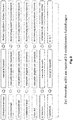
- Fig. 2 shows an overview of the filter criteria.
- the filter criteria designated 1, 6 and 7 are manually selectable filter criteria. This is the occlusion concept, the tooth line and the tooth shape, with on the right side the Fig. 2 Examples of possible choices offered to users are given.
- the user enters the nose width manually, as described later Fig. 10 explained.
- the skelectal class and the type of bite are entered manually or determined automatically by the system. With the help of the stored algorithms, the corresponding criteria are determined automatically.
- the combination of all filter criteria is used to select the ideal setup based on the large number of different setups stored in a database.
- Base points or landmarks are defined for the individual calculations to be carried out.
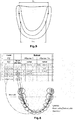
- the lower jaw is as in Fig. 3 shown digitized in the computer.
- the two mesial points rdl and rdr on the left (I) and on the right side (r) of the lower jaw are defined as base points.
- the two lowest points mvr and mvl of the oral cavity atrium are defined on the right and left side next to the little ribbon.
- the left and right points Tuber Maxillae (tr, tl) are also defined. Furthermore, the point papilla incisiva (pi) is determined essentially on the side of the upper jaw opposite the lip ligament of the lower jaw.
- the distance d r determined. This is the distance between the two mesial points rdr and rdl. The distance r d is then multiplied by a factor y in order to obtain the transverse dimension t mm according to equation 1.
- a list can be determined as an example. Set-ups with the same anterior tooth size can have different dental arch dimensions.
- the transverse dimension of the position t ma , middle fissure 36:46 is used via the filter criterion to select a suitable position.
- T ma must lie within the determined transverse dimension T mm ⁇ 1.5mm.
- Fig. 7 To determine the skeletal class, first as in Fig. 7 shown the two defined mesial points rdl and rdr connected to each other and the center point rdm determined between these two points. Accordingly, the two points in the oral vestibule mvr and mvl are connected to each other and their center point mvm is determined. This results in a connecting line b. To define a connecting line h ( Fig. 8 ) the point mvm is connected to the point pi defined on the upper jaw ( Fig. 4 ) this gives the angle k c . Furthermore, a connecting line a) is defined between the points rdm and pi. The angle is calculated using equation 6.
- the bite type is calculated using equation 8 and using equation 9 and using the method shown in Fig. 9 represented geometry.
- the distances v between the points rdr and tr and w between the points rdl and tl are defined.
- the distances p between points rdl and tr and q between points rdr and tl are also defined. From equations 7 and 8, the angles ⁇ and ⁇ can then be determined. This then gives the type of bite.
- I1 + I2 is added to the nose width n, I1, I2 usually being in the range of 0.5-3.5 mm.
- the landmarks or base points with the corresponding coordinates result from the oral patient situations read or digitized in the CAD program.
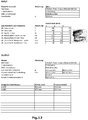
- filtering is then carried out according to the example in Fig. 11 three and the example in Fig. 12 two suitable statements from a large number of statements stored in a database.
- the dental technician then only needs to choose from the determined suitable tooth configurations. Sources of error in the creation of the tooth (partial) prosthesis, for example due to incorrectly adapted individual teeth, are completely eliminated.
- the dental technician is given an optimal starting point for creating the dental (partial) prosthesis without the experience or manual dexterity of the dental technician being important.
Landscapes
- Health & Medical Sciences (AREA)
- Oral & Maxillofacial Surgery (AREA)
- Dentistry (AREA)
- Epidemiology (AREA)
- Life Sciences & Earth Sciences (AREA)
- Animal Behavior & Ethology (AREA)
- General Health & Medical Sciences (AREA)
- Public Health (AREA)
- Veterinary Medicine (AREA)
- Dental Tools And Instruments Or Auxiliary Dental Instruments (AREA)
Description
- Die Erfindung betrifft ein Verfahren zur Festlegung einer Zahnaufstellung für die Herstellung von Zahnvoll- und/oder Zahnteilprothesen.
- Bei der Versorgung von Patienten mit dentalen Teil- oder Vollprothesen ist heutzutage ein hoher Standard festzustellen. Der Zahnarzt bereitet die zur Versorgung vorgesehene Situation am Patienten vor, während die Zahn(teil)prothese üblicherweise in einem externen Labor oder einem Praxislabor von einem Zahntechniker nach den Vorgaben des Zahnarztes hergestellt wird. Die Qualität der Prothese ist dabei in großem Maße abhängig von der handwerklichen Geschicklichkeit des Zahntechnikers, der die Vorgaben des Zahnarztes in der Herstellung der Prothese berücksichtigen muss, sowie der Qualität dieser Vorgaben.
- Des Weiteren ist die Vorbereitung des prothetisch zu versorgenden Patienten für diesen oftmals mit Unannehmlichkeiten verbunden. Erwähnt seien in diesem Zusammenhang beispielsweise verschiedene Sitzungen beim behandelnden Zahnarzt, in denen Abformungen der zu versorgenden Situation vorgenommen werden müssen, die dem Zahntechniker als Negativmodelle dienen. Die sich anschließenden weiteren Abformungen sind zeitaufwendig und oftmals der Grund für fehlerhafte Ausführung der prothetischen Versorgung. Typischerweise sind zwei oder drei Abformungssitzungen erforderlich, bevor der Zahntechniker mit der eigentlichen Herstellung der Prothese beginnen kann.
- Üblicherweise erfolgt die Zahnaufstellung durch den Zahntechniker zahnweise. Verschiedene Aufstellungsverfahren wie beispielsweise die Aufstellung nach Staub (s. z.B.
US 2010/151417 A1 ) helfen dabei dem Zahntechniker bei der Erstellung einer geeigneten Zahnaufstellung. Nachteilig hierbei ist jedoch, dass eine optimale Passform der einzelnen Zähne der Zahnaufstellung zueinander gefunden muss, wobei gleichzeitig die anatomischen Gegebenheiten beim Patienten berücksichtigt werden müssen, als auch das Zusammenspiel zwischen den Zähnen des Oberkiefers und des Unterkiefers. Auf Grund der Verwendung einzelner Zähne als Ausgangspunkt der Zahnaufstellung ergibt sich eine große Anzahl an Realisierungsmöglichkeiten und damit einhergehend eine große Anzahl an Fehlerquellen, die zu einer fehlerhaften Zahnaufstellung führen und damit beim Pateinten Beschwerden auslösen können. -
WO 2011/066895 A1 betrifft ein Verfahren für die automatisierte Herstellung von Zahnersatz, umfassend die Schritte Bereitstellen eines digitalen Datensatzes der herzustellenden individuellen Prothese, digitale Trennung des Modells in Zahnbogen und Zahnfleisch, Herstellung des Zahnbogens aus Keramik und Kunststoff mittels Frästechnik oder Herstellung der Prothesenbasis durch generative oder abtragende Methoden aus überwiegend (Meth)-Acrylat-basierten Kunststoffen, den Anschluss des Zahnbogens und das Zahnfleisch durch Kleben oder Verbinden oder eine Kombination von Kleben und Fügen. -
EP 1 864 627 A2 offenbart ein Verfahren zur Herstellung von Zahnprothesen nach einem digitalisierten, virtuellen Modell, welches die Kiefersituation wiedergibt, mit den Schritten einer digitalen Erfassung der Kiefersituation und-relationen, digitalen Aufstellung (automatisch als Option), Erzeugung einer geteilten Negativform (Rapid Manufacturing) aus den Daten der digitalen Zahnaufstellung, Einstecken der Konfektionszähne/ konfektionierten Zahneinheiten in die geöffneten Negativformen, Schließen der Negativformen, und Ausfüllen der verbliebenen Hohlräume mit Prothesenkunststoff. -
EP 1 444 965 A2 betrifft ein Verfahren zur Herstellung von Zahnersatz, mit den Schritten, Aufnahme und Digitalisierung (Einscannen) der 3-dimensionalen, anatomischen Verhältnisse in der Mundhöhle, gegebenenfalls Aufnahme und Digitalisierung (Einscannen) der 3-dimensionalen Daten von Bissschablonen incl. Bisswällen, gegebenenfalls Aufnahme der Kieferdaten, die normalerweise am Patienten zur Einstellung des Artikulators genommen werden, erhaltenen Verarbeitung des Datensatzes in der Weise, dass die relevanten anatomischen Strukturen für eine virtuelle Zahnaufstellung festliegen und ein virtuelles Modell als Datensatz erhalten wird, gefolgt von der Auswahl der 3-D Datensätze konfektionierter, vorher eingescannter Zähne aus einem weiteren Datensatz, virtuelle Aufstellung der Zähne in das virtuelle Modell als zweiten Datensatz sowie entweder gefolgt von einem Übertragen der virtuellen Aufstellung auf das Modell durch entweder Positionierschablone (z.B. gefräst oder Rapid Prototyped) oder direkte Aufstellung der konfektionierten Zähne auf das Modell, Fixierung der Zähne auf dem Modell, Anbringen der Prothesenbasis oder in einer anderen Alternative, gefolgt von einer direkten Herstellung der Prothesenbasis - nach den Daten der virtuellen Zahnaufstellung - mit Positionierhilfen für die endgültige korrekte Positionierung und Fixierung der konfektionierten Zähne. Dieses Verfahren zur Herstellung von Zahnersatz ist äußerst aufwendig. Insbesondere ist der Aufwand hoch um einen präzisen Zahnersatz herzustellen. -
US 2010/151417 A1 bezieht sich auf ein Verfahren und System zur Planung von zahnärztlichen Restaurationsverfahren und zur Herstellung von Zahnersatz und/oder zahntechnischen Komponenten im Zusammenhang mit den zahnärztlichen Restaurationsverfahren. - Aufgabe der Erfindung ist es, ein Verfahren zur Festlegung einer Zahnaufstellung für die Herstellung von Zahnvollprothesen oder Teilprothesen zu schaffen, mit dem auf möglichst einfache Weise eine zufriedenstellende Auswahl der Zahnaufstellung erfolgen kann.
- Die Lösung der Aufgabe erfolgt erfindungsgemäß durch die Merkmale des Anspruchs 1.
- Zunächst erfolgt das Erfassen der oralen Patientensituation. Dies kann durch bekannte Verfahren beispielsweise durch Abformen und Bissnahme und/oder mittels digitaler Aufnahmen und gegebenenfalls Digitalisierung der oralen Patientensituation erfolgen. Beispielsweise beim Verwenden von Bissschablonen für den Ober- und den Unterkiefer erfolgt ein Abdruck der aktuellen Patientensituation. Diese kann digitalisiert werden, wobei das Negativ der Bissschablone die tatsächliche orale Patientensituation abbildet, so dass diese im Rechner abgebildet ist. Eine entsprechende Abbildung der oralen Patientensituation kann auch durch unmittelbares digitales Abtasten der Patientensituation erfolgen. Als Ergebnis ist stets die tatsächliche orale Patientensituation im Rechner abgebildet. Erfindungsgemäß erfolgt zunächst ein Bestimmen von Koordinaten definierter Basispunkte eines Unter- und/oder eines Oberkiefers. Dies erfolgt vorzugsweise mittels des im Rechner abgebildeten Unterkiefers- und/oder Oberkiefers, das heißt der abgebildeten oralen Patientensituation.
- Auf Grundlage der koordinatendefinierten Basispunkte ist es möglich, für den Unterkiefer und/oder den Oberkiefer ein Transversalmaß und/oder eine skelettale Klasse und/oder eine Bissart zu ermitteln. Hierbei ist es insbesondere bevorzugt, dass insbesondere zwei und besonders bevorzugt drei dieser Merkmale möglichst detailliert bestimmt werden. Je mehr Merkmale und je detaillierter diese Merkmale bestimmt werden, desto qualitativ hochwertiger ist die Festlegung der Zahnaufstellung. Ein vollständiges und aufwendiges Vermessen der Mundhöhle des Patienten ist nicht erforderlich. Die Bestimmung der Merkmale erfolgt lediglich durch Erfassung einzelner Basispunkte. Hierdurch ist das Verfahren schnell und weniger aufwendig.
- Im nächsten Schritt erfolgt sodann eine Auswahl einer passenden Zahnaufstellung auf Grundlage der ermittelten Daten, das heißt auf Grundlage des ermittelten Transversalmaßes und/oder der ermittelten skelettalen Klasse und/oder der ermittelten Bissart. Die Zahnaufstellung kann dabei ausgewählt werden aus einer Vielzahl möglicher Zahnaufstellungen. Hierbei ist es insbesondere nicht mehr erforderlich einzelne Zähne in einer Zahnaufstellung zusammenzufügen. Vielmehr wird die passende Zahnaufstellung, welche bereits optimal zueinander passende künstliche Zähne enthält, ausgewählt anhand der ermittelten Daten. Ein Anpassen der künstlichen Zähne zueinander innerhalb der Zahnaufstellung und die damit verbundenen Fehlerquellen entfallen hierdurch. Insbesondere wird auch die Bissfunktion von Ober- und Unterkiefer zueinander berücksichtigt, so dass mit Auswahl der passenden Zahnaufstellung bereits eine optimale Interaktion zwischen den Zähnen des Oberkiefers und des Unterkiefers gewährleistet ist, ohne dass weitreichende und aufwendige Anpassungen erforderliche werden. Insbesondere ist es durch die algorithmische Auswahl der passenden Zahnaufstellung möglich die Anzahl erforderlicher Sitzungen des Patienten zu Anpassung der Zahn(teil)prothese zu reduzieren und somit den Aufwand für Patient und Zahnarzt zu reduzieren. Gleichzeitig ist es hierdurch möglich schneller Zahnersatz bereitzustellen.
- Die ermittelte Zahnaufstellung und somit die festgelegten künstlichen Zähne werden sodann in einem weiteren Schritt in eine angefertigte Prothesenbasis eingesetzt. Die Herstellung der Prothesenbasis kann hierbei beispielsweise durch ein CAD/CAM-System wie in
WO 2015/078701 beschrieben erfolgen. - Erfindungsgemäß wird die passende Zahnaufstellung ausgewählt aus einer Vielzahl von vorherbestimmten Zahnaufstellungen. Diese können beispielsweise in einer Datenbank hinterlegt sein. Hierdurch wird das Verfahren zur Erstellung einer Zahn(teil)prothese deutlich vereinfacht und insbesondere beschleunigt, da nicht mehr aufwendig einzelne Zähne herausgesucht werden müssen, um diese dann zu einer Zahnaufstellung zusammen zu führen.
- In besonders bevorzugter Ausführungsform der Erfindung erfolgt das Bestimmen des Transversalmaßes als Abstand der tiefsten Stellen des Kieferkamms. Dies erfolgt vorzugsweise aufgrund der im Rechner abgebildeten tatsächlichen oralen Patientensituation des Ober- und/oder Unterkiefers. Hierzu ist es insbesondere bevorzugt, dass die Basispunkte die am weitesten mesial gelegenen Punkte der retromolaren Dreiecke auf der rechten und linken Seite des Unterkiefers umfassen. Das Transversalmaß kann sodann vorzugsweise aus dem Abstand zwischen den beiden am weitesten mesial gelegenen Punkten erfolgen.
- Das Transversalmaß kann somit vorzugsweise ermittelt werden durch

- tmm das Transversalmaß
- rd die Strecken zwischen den mesialen Punkten des retromolaren Dreiecks und
- y der Umrechnungsfaktor ist.
- In bevorzugter Ausführungsform werden die Koordinaten der entsprechenden Basispunkte, das heißt zur Ermittlung des Transversalmaßes die Koordinaten der beiden mesialsten Punkte der retromolaren Dreiecke ermittelt. Der Abstand dr berechnet sich bei der Verwendung von kartesischen Koordinaten aus

- Zusätzlich oder anstelle der Bestimmung des Transversalmaßes erfolgt in bevorzugter Ausführungsform ein Bestimmen der skelettalen Klassen, das heißt insbesondere ein Bestimmen, ob ein Vorbiss oder eine Überbiss vorliegt. Zur Ermittlung der skelettalen Klasse ist es bevorzugt zusätzlich zu den mesial gelegenen Punkten des retromolaren Dreiecks die tiefsten Punkte des Mundhöhlenvorhofs auf der rechten und linken Seite neben dem Lippenbändchen des Unterkiefers zu bestimmen und als zusätzlich Basispunkte zu definieren. Insbesondere mit Hilfe dieser Basispunkte erfolgt ein Bestimmen eines Bisswinkels kc und eine Bisshöhe h, die sodann zur Ermittlung der skelettalen Klasse genutzt wird.
- Hierbei kann zur Ermittlung des Bisswinkels kc zunächst eine Mittellinie zwischen den beiden definierten mesial gelegenen Punkten und den beiden tiefsten Punkten des Mundhöhlenvorhofs bestimmt werden. Die zweite Linie wird sodann durch eine Verbindungslinie zwischen dem Mittelpunkt der beiden tiefsten Punkte der Mundhöhlenvorhöfe und einem Punkt am Oberkiefer, dem Punkt Papilla Incisiva definiert.
- Der Absatz zwischen dem mittleren Punkt zwischen den beiden tiefsten Punkten der Mundhöhlenvorhöfe und dem Punkt Papilla Incisiva definiert ferner die Bisshöhe h.
- Zur mathematischen Bestimmung werden die Koordinaten der beiden mesialen Punkte rdr und rdl sowie der beiden tiefsten Punkte des Mundhöhlenvorhofs mvr und mvl bestimmt zu:

- Die gesuchten Mittelpunkte


- Ferner wurden die Koordinaten des Punktes Papilla Incisiva pi (xpi; ypi; zpi) bestimmt. Hieraus kann die Bisshöhe h sowie der Bisswinkel kc berechnet werden durch

- Auf Basis der erhaltenen Werte für den Bisswinkel kc und die Bisshöhe h kann automatisch eine skelettale Klasse festgelegt werden. Dies erfolgt insbesondere durch hinterlegte Grenzwerte. Beispielsweise liegt von der skelettalen Klasse vor:

- Selbstverständlich ist es auch möglich, Zwischenklassen zu definieren, um eine weitere Verfeinerung des erfindungsgemäßen Verfahrens zu realisieren.
- Zur automatischen Bestimmung der Bissart werden zwei interalveoläre Verbindungswinkel α beziehungsweise β bestimmt. Der auf der linken Seite des Unterkiefers zu bestimmende Winkel α kann berechnet werden aus

w der Abstand zwischen dem linken am weitesten mesial gelegenen Punkt und dem linken Punkt Tuber Maxillae ist. - Der Winkel β auf der rechten Seite kann bestimmt werden durch

v der Abstand zwischen dem rechten am weitesten mesial gelegenen Punkt und dem rechten Punkt Tuber Maxillae ist. - Als Bissart ergibt sich aus den Berechnungen sodann

- In besonderes bevorzugter Ausführungsform der Erfindung erfolgt somit auf Basis des ermittelten Transversalmaßes, der ermittelten skelettalen Klasse und der ermittelten Bissart durch das System ein Vorschlag einer Auswahl für eine passende Zahnstellung. Aus einer großen Anzahl von Zahnaufstellungen, die 10 bis 20 Zahnaufstellungen umfassen kann, wird dem Zahntechniker oder Zahnarzt mit Hilfe des erfindungsgemäßen Verfahrens eine Auswahl von maximal 2 bis 5 Aufstellungen angeboten, die sich maßgeblich durch ästhetische Formabweichungen in der Front unterscheiden.
- Eine derart geringe Anzahl von möglichen Aufstellungen erfolgt einerseits durch die automatische Berechnung des Transversalmaßes, der skelettalen Klasse und der Bissart, sowie insbesondere auch aufgrund manueller Auswahlen. Insbesondere erfolgt eine manuelle Auswahl eines Okklusionskonzepts und/oder einer Zahnlinie und/oder einer Zahnform.
- Bei dem Okklusionskonzept kann der Anwender vorzugsweise aus mehreren Okklusionskonzepten auswählen. Hierbei handelt es sich insbesondere um eine Auswahl nach:
- Aufstellung über Bukkalkontakte
- Aufstellung lingualisiert
- Aufstellung nach Prof. Dr. Dr. Grunert
- Aufstellung nach Prof. Dr. Gerber
- In bevorzugter Ausführungsform werden dem Benutzer für die Auswahl der Zahnlinie ebenfalls unterschiedliche Zahnlinienkombinationen angeboten.
- Hierbei handelt es sich beispielsweise um:
- - VITAPAN PLUS® (Frontzähne) und VITA LINGOFORM® (Seitenzähne)
- - VITAPAN EXCELL® (Frontzähne) und VITA LINGOFORM® (Seitenzähne)
- - - VITA VIONIC® (Front- und Seitenzähne)
- Vorzugsweise wird dem Benutzer auch bei der Zahnform eine Auswahl angeboten. Hierbei handelt es sich beispielsweise um:
- Form R (Rechteckig)
- Form O (Schaufelförmig)
- Form T (Dreieckig)
- Bei einer weiteren bevorzugten Ausführungsform der Erfindung, durch die die Anzahl und/oder die Qualität der nach der Berechnung angebotenen Aufstellung verringert bzw. verbessert werden kann, erfolgt das Auswählen einer Frontzahngarnitur auf Basis der Nasenbreite. Hierbei ist es ausreichend die insbesondere ausreichend die Nasenbreite ebenfalls in das System einzugeben. Hierbei wird die Nasenbreite gegebenenfalls mit einem Faktor multipliziert. Der Faktor liegt vorzugsweise im Bereich von ca. +/- 2mm
- Nachstehend wird die Erfindung anhand der anliegenden Zeichnungen bezüglich einer bevorzugten Ausführungsform näher erläutert.
- Es zeigen:
- Fig. 1
- ein schematisches Ablaufdiagramm für die Auswahl einer bestmöglichen Aufstellung für den Patienten unter Zuhilfenahme des erfindungsgemäßen Verfahrens,
- Fig. 2
- eine Übersicht der Filterkriterien,
- Fig. 3
- eine schematische Ansicht eines digitalisierten Unterkiefers mit den zu bestimmenden Basispunkten,
- Fig. 4
- eine schematische Ansicht eines digitalisierten Oberkiefer mit den zu bestimmenden Basispunkten,
- Fig. 5
- eine schematische Ansicht des digitalen Unterkiefers zur Bestimmung des Transversalmaßes,
- Fig. 6
- eine Tabelle sowie eine Skizze zur Ermittlung des Transversalmaßes,
- Fig. 7
- eine schematische digitale Ansicht des Unterkiefers zur Ermittlung der skelettalen Klasse,
- Fig. 8
- eine schematische Seitenansicht des digitalisierten Unter- und Oberkiefers zur Ermittlung der Bisshöhe h und des Bisswinkels kc,
- Fig. 9
- eine schematische Rückansicht des digitalisierten Ober- und Unterkiefers zur Ermittlung der Bissart,
- Fig. 10
- eine schematische Ansicht zur Ermittlung des Garniturmaßes und
- Fig. 11 und 12
- Beispiele von mit dem erfindungsgemäßen Verfahren bestimmten Aufstellungen.
- In
Fig. 1 ist schematisch der wesentliche Ablauf zur Auswahl einer idealen Zahnaufstellung dargestellt. In einem ersten Schritt wird die Software, bei der es sich insbesondere um eine CAD Software handelt gestartet. Hierbei erfolgt insbesondere auch das Einlesen der digitalisierten oralen Patientensituation, wobei dies selbstverständlich auch zu einem früheren Zeitpunkt bereits erfolgt sein kann. In den nächsten Schritten erfolgt einerseits eine manuelle Auswahl von Filterkriterien und andererseits eine automatische Ermittlung von Filterkriterien auf Grundlage von Berechnungen. Sämtliche Filterkriterien werden sodann im nächsten Schritt zur Filterung der Datenbank, in der die Vielzahl von Zahnaufstellungen hinterlegt ist, genutzt. Hieraus ergibt sich eine Auswahl von nur wenigen geeigneten Zahnaufstellungen, aus denen sodann insbesondere der Zahntechniker auswählen kann. Bei den Zahnaufstellungen handelt es sich um bereits zu einer (Teil-)Zahnreihe zusammengefügte künstliche Zähne, welche zueinander optimal angepasst sind. Einzelzähne müssen somit nicht mehr zusammengefügt werden, sondern sind bereits in der Zahnaufstellung enthalten. -
Fig. 2 zeigt eine Übersicht der Filterkriterien. Hierbei sind die mit 1, 6 und 7 bezeichneten Filterkriterien manuell auszuwählende Filterkriterien. Hierbei handelt es sich um das Okklusionskonzept, die Zahnlinie und die Zahnform, wobei auf der rechten Seite derFig. 2 Beispiele möglicher, für die Benutzer angebotener Auswahlen angegeben sind. - Für die Bestimmung des Garniturmaßes erfolgt vom Benutzer eine manuelle Eingabe der Nasenbreite, wie später an
Fig. 10 erläutert. - Zur Bestimmung des Transversalmaßes, der skelektalen Klasse und der Bissart werden unterschiedliche Basispunkte bzw. Landmarks manuell eingegeben oder vom System automatisch ermittelt. Mit Hilfe der hinterlegten Algorithmen werden die entsprechenden Kriterien automatisch bestimmt.
- Die Kombination sämtlicher Filterkriterien erfolgt zur Auswahl der idealen Aufstellung anhand der in einer Datenbank hinterlegten großen Anzahl unterschiedlicher Aufstellungen.
- Für die einzelnen durchzuführenden Berechnungen werden Basispunkte bzw. Landmarks definiert. Hierzu wird der Unterkiefer wie in
Fig. 3 dargestellt digitalisiert im Rechner abgebildet. Als Basispunkte werden die beiden mesial gelegenen Punkte rdl und rdr auf der linken (I) bzw. auf der rechten Seite (r) des Unterkiefers definiert. - Ferner werden die beiden tiefsten Punkte mvr und mvl des Mundhöhlenvorhofs auf der rechten und linken Seite neben dem Lippenbändchen definiert.
- Da der Oberkiefer ebenfalls in digitalisierter Form in dem Rechner abgebildet ist (
Fig. 4 ), erfolgt ferner die Definition des linken und rechten Punktes Tuber Maxillae (tr, tl). Ferner wird im Wesentlichen auf der dem Lippenbändchen des Unterkiefers gegenüberliegenden Seite des Oberkiefers der Punkt Papilla Incisiva (pi) ermittelt. - Zur Ermittlung des Transversalmaßes wird, wie in
Fig. 5 dargestellt, der Abstand dr ermittelt. Bei diesem handelt es sich um den Abstand zwischen den beiden mesialen Punkten rdr und rdl. Der Abstand rd wird sodann mit einem Faktor y multipliziert um gemäß Gleichung 1 das Transversalmaß tmm zu erhalten. - Auf Basis des ermittelten Transversalmaßes kann, wie in
Fig. 6 beispielhaft dargestellt eine Aufstellung ermittelt werden. Hierbei können Aufstellungen mit gleicher Frontzahngröße unterschiedliche Zahnbogenmaße aufweisen. Im dargestellten Beispiel wird über das Filterkriterium das Transversalmaß der Aufstellung tma, Mittelfissur 36:46 genutzt, um eine passende Aufstellung auszuwählen. Tma muss hierbei innerhalb des ermittelten Transversalmaßes Tmm ± 1,5mm liegen. - Zur Ermittlung der skelettalen Klasse werden zunächst wie in
Fig. 7 dargestellt die beiden definierten mesialen Punkte rdl und rdr miteinander verbunden und der Mittelpunkt rdm zwischen diesen beiden Punkten bestimmt. Entsprechend werden die beiden Punkte im Mundvorhof mvr und mvl miteinander verbunden und wiederum deren Mittelpunkt mvm bestimmt. Diese ergibt eine Verbindungslinie b. Zur Definition einer Verbindunglinie h (Fig. 8 ) erfolgt ein Verbinden des Punktes mvm mit dem am Oberkiefer definierten Punkt pi (Fig. 4 ) hieraus ergibt sich der Winkel kc. Des Weiteren wird eine Verbindungslinie a) zwischen den Punkten rdm und pi definiert. Die Berechnung des Winkels erfolgt über die Gleichung 6. - Die Berechnung der Bissart erfolgt anhand der Gleichung 8 und anhand der Gleichung 9 sowie anhand der in
Fig. 9 dargestellten Geometrie. Zusätzlich zu dem Abstand dr zwischen den Punkten rdr und rdl werden die Strecken v zwischen den Punkten rdr und tr sowie w zwischen den Punkten rdl und tl definiert. Des Weiteren erfolgt eine Definition der Strecken p zwischen den Punkten rdl und tr sowie q zwischen den Punkten rdr und tl. Aus den Gleichungen 7 und 8 können sodann die Winkel α und β bestimmt werden. Hieraus ergibt sich sodann die Bissart. - Zur Bestimmung der Frontzahngarnitur erfolgt ein Messen der Nasenbreite n (
Fig. 10 ). Zur Nasenbreite n wird I1 + I2 addiert, wobei I1, I2 üblicherweise im Bereich von 0,5 - 3,5 mm liegen. I1 und I2 entsprechen dem Abstand zwischen einer Außenseite des Nasenflügels und einer Außenseite des Eckzahns wie inFig. 10 dargestellt. Hieraus ergibt sich das Garniturmaß g entsprechend der Gleichung
- Wie in den
Fign. 11 und12 sind Beispiele für Berechnungen dargestellt. Als manuelle Auswahl bzw. Eingabe erfolgt das Eingeben der Zahnlinie, der Frontzahnform, des Okklusionskonzepts und der Nasenbreite. - Beispiel: Nasenbreite 40mm (Eckzahnmitte zu Eckzahnmitte), Zahnform gemäß Typ O
- g = 3,0 + 3,0 + 40 [mm]
- g = 46,0, was ungefähr O45 entspricht
- Aus den in das CAD Programm eingelesenen bzw. digitalisierten oralen Patientensituationen ergeben sich die Landmarken bzw. Basispunkte mit den entsprechenden Koordinaten. Mit Hilfe erfindungsgemäßen Verfahrens erfolgt sodann ein Filtern von gemäß dem Beispiel in
Fig. 11 drei und dem Beispiel inFig. 12 zwei geeigneten Aufstellungen aus einer Vielzahl in einer Datenbank hinterlegten Aufstellungen. Der Zahntechniker braucht sodann lediglich aus den ermittelten passenden Zahnaufstellungen zu wählen. Fehlerquellen bei der Erstellung der Zahn(teil)prothese beispielsweise durch fehlerhaft zueinander angepasste Einzelzähne entfallen vollständig. Dem Zahntechniker wird ein optimaler Ausgangspunkt zur Erstellung der Zahn(teil)prothese gegeben, ohne dass es hierbei auf die Erfahrung bzw. handwerkliche Geschicklichkeit des Zahntechnikers ankommt.
Claims (15)
- Computerimplementiertes Verfahren zur Festlegung einer Zahnaufstellung für die Herstellung von Zahnteil- oder Vollprothese mit den Schritten:Bestimmen von durch Koordinaten definierte Basispunkte eines Unterkiefers und/oder einer Oberkiefers;Ermitteln eines Transversalmaßes und/oder einer skelettalen Klasse und/oder einer Bissart auf Basis der bestimmten Koordinaten für den Unterkiefer und/oder den Oberkiefer undAuswahl, aus einer Vielzahl von vorherbestimmten Zahnaufstellungen, einer passenden Zahnaufstellung, welche zueinander passende künstliche Zähne enthält auf Grundlage des ermittelten Transversalmaßes und/oder der ermittelten skelettalen Klasse und/oder der ermittelten Bissart.
- Computerimplementiertes Verfahren nach Anspruch 1, dadurch gekennzeichnet, dass die Basispunkte, die am weitesten mesial gelegenen Punkte (rdl, rdr) der retromolaren Dreiecke auf der rechten und linken Seite des Unterkiefers umfassen.
- Computerimplementiertes Verfahren nach Anspruch 1 oder 2, dadurch gekennzeichnet, dass die Basispunkte, die tiefsten Punkte (mvl, mvr) des Mundhöhlenvorhofs auf der rechten und linken Seite neben dem Lippenbändchen der Unterkieferbasis umfassen.
- Computerimplementiertes Verfahren nach einem der Ansprüche 1 bis 3, dadurch gekennzeichnet, dass die Basispunkte die Punkte (tl, tr) Tuber Maxillae auf der rechten und linken Seite des Oberkiefers umfassen.
- Computerimplementiertes Verfahren nach einem der Ansprüche 1 bis 4, dadurch gekennzeichnet, dass die Basispunkte den Punkt (pi) Papilla Incisiva des Oberkiefers umfassen.
- Computerimplementiertes Verfahren nach einem der Ansprüche 2 bis 5, dadurch gekennzeichnet, dass das Transversalmaß (tmm) zumindest auf Basis des Abstandes (rd) der mesialen Punkte (tl, tr) des retromolaren Dreiecks ermittelt wird.
- Computerimplementiertes Verfahren nach Anspruch 6, dadurch gekennzeichnet, dass das Transversalmaß mit einem Korrekturfaktor (y) multipliziert wird.
- Computerimplementiertes Verfahren nach einem der Ansprüche 1 bis 7, dadurch gekennzeichnet, dass eine skelettale Klasse auf Basis eines Bisswinkels (kc) und einer Bisshöhe (h) ermittelt wird.
- Computerimplementiertes Verfahren nach Anspruch 8, bei welchem der Bisswinkel (kc) zwischen einer Mittellinie (b), die in der Mitte (mdm, mvm) zwischen den am weitesten mesial gelegenen Punkten (tdl, tdr) und den tiefsten Punkten (mvl, mvr) der Mundhöhlenvorhöfe verläuft und einer Verbindungslinie (h) zu dem Punkt (pi) Papilla Incisiva verläuft.
- Computerimplementiertes Verfahren nach Anspruch 8 oder 9, wobei die Bisshöhe (h) bestimmt wird als Abstand zwischen dem Mittelpunkt mvm der beiden tiefsten Punkte (mvl, mvr) im Mundvorhof und dem Punkt (pi) Papilla Incisiva.
- Computerimplementiertes Verfahren nach einem der Ansprüche 1 bis 10, bei welchem die Bissart auf Basis der interalveolären Verbindungswinkel (α, β) bestimmt wird.
- Computerimplementiertes Verfahren nach Anspruch 11, bei welchem die Verbindungswinkel (α, β) bestimmt werden durch die Verbindungslinie (v, w, dr) zwischen den beiden am weitesten mesial gelegenen Punkten (tr, tl) des retromolaren Dreiecks und dem linken bzw. rechten Punkt (tr, tl) Tubera.
- Computerimplementiertes Verfahren nach Anspruch 11 oder 12, bei welchem ein Normalbiss bestimmt wird, wenn die beiden Verbindungswinkel ≤80° sind, bei welchem ein beidseitiger Kreuzbiss bestimmt wird, wenn die beiden Verbindungswinkel ≥80° sind und bei welchem einer einseitiger Kreuzbiss bestimmt wird, wenn nur einer der beiden Verbindungswinkel ≥80° ist.
- Computerimplementiertes Verfahren nach einem der Ansprüche 1 bis 13, bei welchem eine Frontzahngarnitur auf Basis einer Nasenbreite n ausgewählt wird, wobei die Nasenbreite (n) gegebenenfalls mit einem Korrekturfaktor (x) multipliziert wird.
- Computerimplementiertes Verfahren nach einem der Ansprüche 1 bis 14, bei welchem zur Auswahl einer Zahnaufstellung für die Unterkieferbasis und/oder die Oberkieferbasis ein Okklusionskonzept und/oder eine Zahnlinie und/oder eine Zahnform ausgewählt werden.
Applications Claiming Priority (2)
| Application Number | Priority Date | Filing Date | Title |
|---|---|---|---|
| EP16169206.6A EP3243481A1 (de) | 2016-05-11 | 2016-05-11 | Verfahren zur festlegung einer zahnaufstellung |
| PCT/EP2017/061047 WO2017194536A1 (de) | 2016-05-11 | 2017-05-09 | Verfahren zur festlegung einer zahnaufstellung |
Publications (2)
| Publication Number | Publication Date |
|---|---|
| EP3454776A1 EP3454776A1 (de) | 2019-03-20 |
| EP3454776B1 true EP3454776B1 (de) | 2020-06-24 |
Family
ID=55963266
Family Applications (2)
| Application Number | Title | Priority Date | Filing Date |
|---|---|---|---|
| EP16169206.6A Withdrawn EP3243481A1 (de) | 2016-05-11 | 2016-05-11 | Verfahren zur festlegung einer zahnaufstellung |
| EP17723059.6A Not-in-force EP3454776B1 (de) | 2016-05-11 | 2017-05-09 | Computerimplementiertes verfahren zur festlegung einer zahnaufstellung |
Family Applications Before (1)
| Application Number | Title | Priority Date | Filing Date |
|---|---|---|---|
| EP16169206.6A Withdrawn EP3243481A1 (de) | 2016-05-11 | 2016-05-11 | Verfahren zur festlegung einer zahnaufstellung |
Country Status (4)
| Country | Link |
|---|---|
| US (1) | US20190117350A1 (de) |
| EP (2) | EP3243481A1 (de) |
| ES (1) | ES2816068T3 (de) |
| WO (1) | WO2017194536A1 (de) |
Families Citing this family (2)
| Publication number | Priority date | Publication date | Assignee | Title |
|---|---|---|---|---|
| EP3527164B1 (de) * | 2018-02-16 | 2021-05-26 | Global Dental Science LLC | Anatomische echtzeitanpassung |
| KR102194777B1 (ko) * | 2020-06-10 | 2020-12-23 | 클리어테크놀로지 주식회사 | 인공지능 기반의 치과 보철 자동 디자인 설계 시스템 및 그 방법 |
Family Cites Families (8)
| Publication number | Priority date | Publication date | Assignee | Title |
|---|---|---|---|---|
| DE10304757B4 (de) | 2003-02-05 | 2005-07-21 | Heraeus Kulzer Gmbh | Vorrichtung und Verfahren zur Herstellung von Zahnersatz |
| JP3820403B2 (ja) * | 2003-12-05 | 2006-09-13 | 株式会社アイキャット | 人工歯根埋入位置特定装置、コンピュータプログラム及び記録媒体 |
| DE102006026776A1 (de) | 2006-06-07 | 2007-12-13 | Heraeus Kulzer Gmbh | Verfahren zur Herstellung einer Zahnprothese |
| EP2156350A1 (de) * | 2007-05-25 | 2010-02-24 | Nobel Biocare Services AG | Verfahren und system für zahnmedizinische planung |
| DE102009056752C5 (de) | 2009-12-04 | 2024-04-04 | Kulzer Gmbh | Herstellung individueller dentaler Prothesen via CAD/CAM und Rapid Manufacturing/Rapid Prototyping aus Daten der digitalen Abdrucknahme |
| ES2945669T3 (es) * | 2012-06-15 | 2023-07-05 | Vita Zahnfabrik H Rauter Gmbh & Co Kg | Procedimiento de preparación de una prótesis dental parcial o completa |
| WO2015078701A1 (de) | 2013-11-26 | 2015-06-04 | Vita Zahnfabrik H. Rauter Gmbh & Co. Kg | Künstlicher zahn sowie verfahren zur herstellung einer prothesenbasis |
| WO2015169910A1 (en) * | 2014-05-09 | 2015-11-12 | 3Shape A/S | Scanning of edentulous patients |
-
2016
- 2016-05-11 EP EP16169206.6A patent/EP3243481A1/de not_active Withdrawn
-
2017
- 2017-05-09 ES ES17723059T patent/ES2816068T3/es active Active
- 2017-05-09 WO PCT/EP2017/061047 patent/WO2017194536A1/de not_active Ceased
- 2017-05-09 EP EP17723059.6A patent/EP3454776B1/de not_active Not-in-force
- 2017-05-09 US US16/300,300 patent/US20190117350A1/en not_active Abandoned
Non-Patent Citations (1)
| Title |
|---|
| None * |
Also Published As
| Publication number | Publication date |
|---|---|
| WO2017194536A1 (de) | 2017-11-16 |
| ES2816068T3 (es) | 2021-03-31 |
| EP3454776A1 (de) | 2019-03-20 |
| US20190117350A1 (en) | 2019-04-25 |
| EP3243481A1 (de) | 2017-11-15 |
Similar Documents
| Publication | Publication Date | Title |
|---|---|---|
| EP1444965B2 (de) | Vorrichtung und Verfahren zur Herstellung von Zahnersatz | |
| EP3618758B1 (de) | Verfahren zur konstruktion eines dentalen bauteils | |
| EP3705080B1 (de) | Computerimplementiertes modellieren eines patientenindividuellen zahnersatzteils | |
| DE102007033989B4 (de) | Verfahren zur herstellung eines aligners mit einem computerimplementierten verfahren für die automatische konstruktion einer okklusionsebene und computerisiertes system | |
| EP2742906B1 (de) | Verfahren und System zum Aufbau einer Dentalprothese | |
| EP2934365B1 (de) | Verfahren zur herstellung eines kieferorthopädischen setups | |
| EP3824844A1 (de) | Verfahren zur konstruktion einer restauration | |
| EP3917447B1 (de) | Verfahren zur herstellung eines zahnersatzes unter verwendung einer digitalen zahnreihendatenbank, und verwendung einer solchen digitalen zahnreihendatenbank | |
| DE102012007706B4 (de) | Verfahren zum Herstellen eines künstlichen Gebisses | |
| EP3503840B1 (de) | Zahneinheit sowie verfahren zur herstellung einer prothesenbasis | |
| EP3073955B1 (de) | Künstlicher zahn sowie verfahren zur herstellung einer prothesenbasis | |
| DE112022004329T5 (de) | Anpassung einer position künstlicher zähne einer zahnprothese | |
| DE102017113814A1 (de) | Verfahren zur Herstellung einer Dentalprothese mit definiertem Klebespalt | |
| DE102017108592A1 (de) | Verfahren zur Herstellung einer Dentalprothese mit parallelen Wurzeln der Prothesenzähne | |
| WO2016083324A1 (de) | Bissnahmewerkzeug, bissnahmewerkzeugset sowie geeignetes verfahren zur bissregistrierung | |
| EP3258880B1 (de) | Passive fit von implantatbrücken und -stegen mittels eines cad/cam tools für die modellfreie erstellung von implantatgetragenen restaurationen | |
| EP3454776A1 (de) | Verfahren zur festlegung einer zahnaufstellung | |
| EP3383312B1 (de) | Verfahren zur anpassung von prothesenzähnen | |
| EP4661797A1 (de) | Verfahren und analysesystem zur erstellung eines digitalen 3d-modells des gebisses eines patienten | |
| DE102023106238B3 (de) | Verfahren und System zur Erzeugung eines Modells zur Verwendung in einem virtuellen Extraktionsverfahren für ein Extraktionszielobjekt an einem Patienten, sowie korrespondierendes Computerprogrammprodukt und Speichermedium für selbiges | |
| EP1304088A1 (de) | Verfahren und Vorrichtung zum Herstellen von Passkörpern zur Restauration von Zähnen | |
| WO2019052915A1 (de) | Verfahren zur ermittlung und visualisierung von zahnbewegungen und geplanten zahnumstellungen | |
| DE202021101562U1 (de) | Herausnehmbarer Teilzahnersatz | |
| WO2016079071A1 (de) | Verfahren zur erstellung eines digitalen artikulators | |
| WO2008040380A1 (de) | Verfahren zur herstellung einer zahntechnischen totalprothese |
Legal Events
| Date | Code | Title | Description |
|---|---|---|---|
| STAA | Information on the status of an ep patent application or granted ep patent |
Free format text: STATUS: UNKNOWN |
|
| STAA | Information on the status of an ep patent application or granted ep patent |
Free format text: STATUS: THE INTERNATIONAL PUBLICATION HAS BEEN MADE |
|
| PUAI | Public reference made under article 153(3) epc to a published international application that has entered the european phase |
Free format text: ORIGINAL CODE: 0009012 |
|
| STAA | Information on the status of an ep patent application or granted ep patent |
Free format text: STATUS: REQUEST FOR EXAMINATION WAS MADE |
|
| 17P | Request for examination filed |
Effective date: 20181112 |
|
| AK | Designated contracting states |
Kind code of ref document: A1 Designated state(s): AL AT BE BG CH CY CZ DE DK EE ES FI FR GB GR HR HU IE IS IT LI LT LU LV MC MK MT NL NO PL PT RO RS SE SI SK SM TR |
|
| AX | Request for extension of the european patent |
Extension state: BA ME |
|
| DAV | Request for validation of the european patent (deleted) | ||
| DAX | Request for extension of the european patent (deleted) | ||
| GRAP | Despatch of communication of intention to grant a patent |
Free format text: ORIGINAL CODE: EPIDOSNIGR1 |
|
| STAA | Information on the status of an ep patent application or granted ep patent |
Free format text: STATUS: GRANT OF PATENT IS INTENDED |
|
| INTG | Intention to grant announced |
Effective date: 20200103 |
|
| REG | Reference to a national code |
Ref country code: HK Ref legal event code: DE Ref document number: 40003616 Country of ref document: HK |
|
| GRAS | Grant fee paid |
Free format text: ORIGINAL CODE: EPIDOSNIGR3 |
|
| GRAA | (expected) grant |
Free format text: ORIGINAL CODE: 0009210 |
|
| STAA | Information on the status of an ep patent application or granted ep patent |
Free format text: STATUS: THE PATENT HAS BEEN GRANTED |
|
| AK | Designated contracting states |
Kind code of ref document: B1 Designated state(s): AL AT BE BG CH CY CZ DE DK EE ES FI FR GB GR HR HU IE IS IT LI LT LU LV MC MK MT NL NO PL PT RO RS SE SI SK SM TR |
|
| REG | Reference to a national code |
Ref country code: GB Ref legal event code: FG4D Free format text: NOT ENGLISH |
|
| REG | Reference to a national code |
Ref country code: CH Ref legal event code: EP |
|
| REG | Reference to a national code |
Ref country code: AT Ref legal event code: REF Ref document number: 1283143 Country of ref document: AT Kind code of ref document: T Effective date: 20200715 |
|
| REG | Reference to a national code |
Ref country code: DE Ref legal event code: R096 Ref document number: 502017005876 Country of ref document: DE |
|
| REG | Reference to a national code |
Ref country code: IE Ref legal event code: FG4D Free format text: LANGUAGE OF EP DOCUMENT: GERMAN |
|
| REG | Reference to a national code |
Ref country code: CH Ref legal event code: NV Representative=s name: ISLER AND PEDRAZZINI AG, CH |
|
| PG25 | Lapsed in a contracting state [announced via postgrant information from national office to epo] |
Ref country code: GR Free format text: LAPSE BECAUSE OF FAILURE TO SUBMIT A TRANSLATION OF THE DESCRIPTION OR TO PAY THE FEE WITHIN THE PRESCRIBED TIME-LIMIT Effective date: 20200925 Ref country code: NO Free format text: LAPSE BECAUSE OF FAILURE TO SUBMIT A TRANSLATION OF THE DESCRIPTION OR TO PAY THE FEE WITHIN THE PRESCRIBED TIME-LIMIT Effective date: 20200924 Ref country code: SE Free format text: LAPSE BECAUSE OF FAILURE TO SUBMIT A TRANSLATION OF THE DESCRIPTION OR TO PAY THE FEE WITHIN THE PRESCRIBED TIME-LIMIT Effective date: 20200624 Ref country code: FI Free format text: LAPSE BECAUSE OF FAILURE TO SUBMIT A TRANSLATION OF THE DESCRIPTION OR TO PAY THE FEE WITHIN THE PRESCRIBED TIME-LIMIT Effective date: 20200624 Ref country code: LT Free format text: LAPSE BECAUSE OF FAILURE TO SUBMIT A TRANSLATION OF THE DESCRIPTION OR TO PAY THE FEE WITHIN THE PRESCRIBED TIME-LIMIT Effective date: 20200624 |
|
| REG | Reference to a national code |
Ref country code: LT Ref legal event code: MG4D |
|
| PG25 | Lapsed in a contracting state [announced via postgrant information from national office to epo] |
Ref country code: RS Free format text: LAPSE BECAUSE OF FAILURE TO SUBMIT A TRANSLATION OF THE DESCRIPTION OR TO PAY THE FEE WITHIN THE PRESCRIBED TIME-LIMIT Effective date: 20200624 Ref country code: HR Free format text: LAPSE BECAUSE OF FAILURE TO SUBMIT A TRANSLATION OF THE DESCRIPTION OR TO PAY THE FEE WITHIN THE PRESCRIBED TIME-LIMIT Effective date: 20200624 Ref country code: LV Free format text: LAPSE BECAUSE OF FAILURE TO SUBMIT A TRANSLATION OF THE DESCRIPTION OR TO PAY THE FEE WITHIN THE PRESCRIBED TIME-LIMIT Effective date: 20200624 Ref country code: BG Free format text: LAPSE BECAUSE OF FAILURE TO SUBMIT A TRANSLATION OF THE DESCRIPTION OR TO PAY THE FEE WITHIN THE PRESCRIBED TIME-LIMIT Effective date: 20200924 |
|
| REG | Reference to a national code |
Ref country code: NL Ref legal event code: MP Effective date: 20200624 |
|
| PG25 | Lapsed in a contracting state [announced via postgrant information from national office to epo] |
Ref country code: NL Free format text: LAPSE BECAUSE OF FAILURE TO SUBMIT A TRANSLATION OF THE DESCRIPTION OR TO PAY THE FEE WITHIN THE PRESCRIBED TIME-LIMIT Effective date: 20200624 Ref country code: AL Free format text: LAPSE BECAUSE OF FAILURE TO SUBMIT A TRANSLATION OF THE DESCRIPTION OR TO PAY THE FEE WITHIN THE PRESCRIBED TIME-LIMIT Effective date: 20200624 |
|
| PG25 | Lapsed in a contracting state [announced via postgrant information from national office to epo] |
Ref country code: PT Free format text: LAPSE BECAUSE OF FAILURE TO SUBMIT A TRANSLATION OF THE DESCRIPTION OR TO PAY THE FEE WITHIN THE PRESCRIBED TIME-LIMIT Effective date: 20201026 Ref country code: SM Free format text: LAPSE BECAUSE OF FAILURE TO SUBMIT A TRANSLATION OF THE DESCRIPTION OR TO PAY THE FEE WITHIN THE PRESCRIBED TIME-LIMIT Effective date: 20200624 Ref country code: EE Free format text: LAPSE BECAUSE OF FAILURE TO SUBMIT A TRANSLATION OF THE DESCRIPTION OR TO PAY THE FEE WITHIN THE PRESCRIBED TIME-LIMIT Effective date: 20200624 Ref country code: CZ Free format text: LAPSE BECAUSE OF FAILURE TO SUBMIT A TRANSLATION OF THE DESCRIPTION OR TO PAY THE FEE WITHIN THE PRESCRIBED TIME-LIMIT Effective date: 20200624 Ref country code: RO Free format text: LAPSE BECAUSE OF FAILURE TO SUBMIT A TRANSLATION OF THE DESCRIPTION OR TO PAY THE FEE WITHIN THE PRESCRIBED TIME-LIMIT Effective date: 20200624 |
|
| PG25 | Lapsed in a contracting state [announced via postgrant information from national office to epo] |
Ref country code: PL Free format text: LAPSE BECAUSE OF FAILURE TO SUBMIT A TRANSLATION OF THE DESCRIPTION OR TO PAY THE FEE WITHIN THE PRESCRIBED TIME-LIMIT Effective date: 20200624 Ref country code: SK Free format text: LAPSE BECAUSE OF FAILURE TO SUBMIT A TRANSLATION OF THE DESCRIPTION OR TO PAY THE FEE WITHIN THE PRESCRIBED TIME-LIMIT Effective date: 20200624 Ref country code: IS Free format text: LAPSE BECAUSE OF FAILURE TO SUBMIT A TRANSLATION OF THE DESCRIPTION OR TO PAY THE FEE WITHIN THE PRESCRIBED TIME-LIMIT Effective date: 20201024 |
|
| REG | Reference to a national code |
Ref country code: DE Ref legal event code: R097 Ref document number: 502017005876 Country of ref document: DE |
|
| REG | Reference to a national code |
Ref country code: ES Ref legal event code: FG2A Ref document number: 2816068 Country of ref document: ES Kind code of ref document: T3 Effective date: 20210331 |
|
| PG25 | Lapsed in a contracting state [announced via postgrant information from national office to epo] |
Ref country code: DK Free format text: LAPSE BECAUSE OF FAILURE TO SUBMIT A TRANSLATION OF THE DESCRIPTION OR TO PAY THE FEE WITHIN THE PRESCRIBED TIME-LIMIT Effective date: 20200624 |
|
| PLBE | No opposition filed within time limit |
Free format text: ORIGINAL CODE: 0009261 |
|
| STAA | Information on the status of an ep patent application or granted ep patent |
Free format text: STATUS: NO OPPOSITION FILED WITHIN TIME LIMIT |
|
| 26N | No opposition filed |
Effective date: 20210325 |
|
| PGFP | Annual fee paid to national office [announced via postgrant information from national office to epo] |
Ref country code: DE Payment date: 20210602 Year of fee payment: 5 Ref country code: IT Payment date: 20210526 Year of fee payment: 5 Ref country code: FR Payment date: 20210525 Year of fee payment: 5 |
|
| PG25 | Lapsed in a contracting state [announced via postgrant information from national office to epo] |
Ref country code: SI Free format text: LAPSE BECAUSE OF FAILURE TO SUBMIT A TRANSLATION OF THE DESCRIPTION OR TO PAY THE FEE WITHIN THE PRESCRIBED TIME-LIMIT Effective date: 20200624 |
|
| PGFP | Annual fee paid to national office [announced via postgrant information from national office to epo] |
Ref country code: ES Payment date: 20210618 Year of fee payment: 5 Ref country code: CH Payment date: 20210525 Year of fee payment: 5 |
|
| GBPC | Gb: european patent ceased through non-payment of renewal fee |
Effective date: 20210509 |
|
| PG25 | Lapsed in a contracting state [announced via postgrant information from national office to epo] |
Ref country code: MC Free format text: LAPSE BECAUSE OF FAILURE TO SUBMIT A TRANSLATION OF THE DESCRIPTION OR TO PAY THE FEE WITHIN THE PRESCRIBED TIME-LIMIT Effective date: 20200624 Ref country code: LU Free format text: LAPSE BECAUSE OF NON-PAYMENT OF DUE FEES Effective date: 20210509 |
|
| REG | Reference to a national code |
Ref country code: BE Ref legal event code: MM Effective date: 20210531 |
|
| PG25 | Lapsed in a contracting state [announced via postgrant information from national office to epo] |
Ref country code: IE Free format text: LAPSE BECAUSE OF NON-PAYMENT OF DUE FEES Effective date: 20210509 Ref country code: GB Free format text: LAPSE BECAUSE OF NON-PAYMENT OF DUE FEES Effective date: 20210509 |
|
| PG25 | Lapsed in a contracting state [announced via postgrant information from national office to epo] |
Ref country code: BE Free format text: LAPSE BECAUSE OF NON-PAYMENT OF DUE FEES Effective date: 20210531 |
|
| REG | Reference to a national code |
Ref country code: DE Ref legal event code: R119 Ref document number: 502017005876 Country of ref document: DE |
|
| REG | Reference to a national code |
Ref country code: CH Ref legal event code: PL |
|
| PG25 | Lapsed in a contracting state [announced via postgrant information from national office to epo] |
Ref country code: LI Free format text: LAPSE BECAUSE OF NON-PAYMENT OF DUE FEES Effective date: 20220531 Ref country code: CH Free format text: LAPSE BECAUSE OF NON-PAYMENT OF DUE FEES Effective date: 20220531 |
|
| PG25 | Lapsed in a contracting state [announced via postgrant information from national office to epo] |
Ref country code: FR Free format text: LAPSE BECAUSE OF NON-PAYMENT OF DUE FEES Effective date: 20220531 |
|
| PG25 | Lapsed in a contracting state [announced via postgrant information from national office to epo] |
Ref country code: DE Free format text: LAPSE BECAUSE OF NON-PAYMENT OF DUE FEES Effective date: 20221201 |
|
| REG | Reference to a national code |
Ref country code: ES Ref legal event code: FD2A Effective date: 20230627 |
|
| PG25 | Lapsed in a contracting state [announced via postgrant information from national office to epo] |
Ref country code: CY Free format text: LAPSE BECAUSE OF FAILURE TO SUBMIT A TRANSLATION OF THE DESCRIPTION OR TO PAY THE FEE WITHIN THE PRESCRIBED TIME-LIMIT Effective date: 20200624 |
|
| REG | Reference to a national code |
Ref country code: AT Ref legal event code: MM01 Ref document number: 1283143 Country of ref document: AT Kind code of ref document: T Effective date: 20220509 |
|
| PG25 | Lapsed in a contracting state [announced via postgrant information from national office to epo] |
Ref country code: IT Free format text: LAPSE BECAUSE OF NON-PAYMENT OF DUE FEES Effective date: 20220509 Ref country code: HU Free format text: LAPSE BECAUSE OF FAILURE TO SUBMIT A TRANSLATION OF THE DESCRIPTION OR TO PAY THE FEE WITHIN THE PRESCRIBED TIME-LIMIT; INVALID AB INITIO Effective date: 20170509 Ref country code: ES Free format text: LAPSE BECAUSE OF NON-PAYMENT OF DUE FEES Effective date: 20220510 Ref country code: AT Free format text: LAPSE BECAUSE OF NON-PAYMENT OF DUE FEES Effective date: 20220509 |
|
| PG25 | Lapsed in a contracting state [announced via postgrant information from national office to epo] |
Ref country code: MK Free format text: LAPSE BECAUSE OF FAILURE TO SUBMIT A TRANSLATION OF THE DESCRIPTION OR TO PAY THE FEE WITHIN THE PRESCRIBED TIME-LIMIT Effective date: 20200624 |
|
| PG25 | Lapsed in a contracting state [announced via postgrant information from national office to epo] |
Ref country code: TR Free format text: LAPSE BECAUSE OF FAILURE TO SUBMIT A TRANSLATION OF THE DESCRIPTION OR TO PAY THE FEE WITHIN THE PRESCRIBED TIME-LIMIT Effective date: 20200624 |
|
| PG25 | Lapsed in a contracting state [announced via postgrant information from national office to epo] |
Ref country code: MT Free format text: LAPSE BECAUSE OF FAILURE TO SUBMIT A TRANSLATION OF THE DESCRIPTION OR TO PAY THE FEE WITHIN THE PRESCRIBED TIME-LIMIT Effective date: 20200624 |
|
| REG | Reference to a national code |
Ref country code: HK Ref legal event code: WD Ref document number: 40003616 Country of ref document: HK |