EP3454568B1 - Mikrofonvorverstärker mit polarisationsspannungsversorgung - Google Patents
Mikrofonvorverstärker mit polarisationsspannungsversorgung Download PDFInfo
- Publication number
- EP3454568B1 EP3454568B1 EP17190512.8A EP17190512A EP3454568B1 EP 3454568 B1 EP3454568 B1 EP 3454568B1 EP 17190512 A EP17190512 A EP 17190512A EP 3454568 B1 EP3454568 B1 EP 3454568B1
- Authority
- EP
- European Patent Office
- Prior art keywords
- voltage
- microphone
- analyzer
- stage
- wires
- Prior art date
- Legal status (The legal status is an assumption and is not a legal conclusion. Google has not performed a legal analysis and makes no representation as to the accuracy of the status listed.)
- Active
Links
Images
Classifications
-
- H—ELECTRICITY
- H04—ELECTRIC COMMUNICATION TECHNIQUE
- H04R—LOUDSPEAKERS, MICROPHONES, GRAMOPHONE PICK-UPS OR LIKE ACOUSTIC ELECTROMECHANICAL TRANSDUCERS; ELECTRIC HEARING AIDS; PUBLIC ADDRESS SYSTEMS
- H04R3/00—Circuits for transducers
-
- H—ELECTRICITY
- H04—ELECTRIC COMMUNICATION TECHNIQUE
- H04R—LOUDSPEAKERS, MICROPHONES, GRAMOPHONE PICK-UPS OR LIKE ACOUSTIC ELECTROMECHANICAL TRANSDUCERS; ELECTRIC HEARING AIDS; PUBLIC ADDRESS SYSTEMS
- H04R1/00—Details of transducers, loudspeakers or microphones
- H04R1/02—Casings; Cabinets ; Supports therefor; Mountings therein
- H04R1/04—Structural association of microphone with electric circuitry therefor
-
- H—ELECTRICITY
- H04—ELECTRIC COMMUNICATION TECHNIQUE
- H04R—LOUDSPEAKERS, MICROPHONES, GRAMOPHONE PICK-UPS OR LIKE ACOUSTIC ELECTROMECHANICAL TRANSDUCERS; ELECTRIC HEARING AIDS; PUBLIC ADDRESS SYSTEMS
- H04R1/00—Details of transducers, loudspeakers or microphones
- H04R1/08—Mouthpieces; Microphones; Attachments therefor
-
- H—ELECTRICITY
- H04—ELECTRIC COMMUNICATION TECHNIQUE
- H04R—LOUDSPEAKERS, MICROPHONES, GRAMOPHONE PICK-UPS OR LIKE ACOUSTIC ELECTROMECHANICAL TRANSDUCERS; ELECTRIC HEARING AIDS; PUBLIC ADDRESS SYSTEMS
- H04R2499/00—Aspects covered by H04R or H04S not otherwise provided for in their subgroups
- H04R2499/10—General applications
- H04R2499/13—Acoustic transducers and sound field adaptation in vehicles
Definitions
- the invention relates to a system of at least one microphone and a remote signal analyzer connected to the microphone with two wires to transmit an audio signal back to the analyzer and to receive a constant input current on one of the wires from the analyzer, which microphone comprises an acoustic sensor and a pre-amplifier powered with the constant input current to amplify the audio signal from the acoustic sensor.
- Measurement microphones are known with two different microphone versions: one pre-polarized and one that requires external polarization. The pre-polarized is more complicated and expensive to make in a measurement quality. Furthermore measurement microphones are known in two different interface versions: The first version is a multi-wire interface with separate wires for power, which includes polarization voltage which enables use of both microphone versions.
- a two wire interface is used, here the power is sourced to the transducer on the same two wires as a constant current and the transducer signal is being overlaid as a voltage on the same two wires.
- a pre-amplifier of the microphone is powered by the constant current of typically 2 to 4mA applied between the wires and the acoustic sensor signal is transmitted back to the analyzer as a voltage on the two wires.
- the applied current is required to drive the preamplifier and capacitive load from the cable; any use of the available current for other purposes will degrade the capability to drive the cable.
- pre-polarized microphone capsules may be used in state of the arte microphones with this second interface version.
- Known power supplies used in these microphones are not able to generate the stabile and high voltage needed from this small input current, which voltage in addition varies with the audio signal of the acoustic sensor. This is a problem as microphones with pre-polarized microphone capsules are more complicated and expensive to make in a measurement quality.
- This object is achieved with a system with a microphone that comprises a polarization voltage supply connected to the two wires to polarize the microphone, which polarization voltage supply comprises: a transformation stage to transform a partial part of the constant input current on the one wire from the remote signal analyzer into an output voltage with a first voltage level and a voltage increaser stage to increase the voltage level of the output voltage into an increased output voltage with a second voltage level and a noise reduction stage to provide a polarization voltage to the acoustic sensor.
- the polarization voltage supply of the claimed system is able to generate the polarization voltage of about 200V from the very limited input current available to power the microphone, by taking only approx. 0.25mA from the available input current.
- the power source for this polarization voltage supply is from a voltage between the two wires varying with the audio signal and the very limited current available primary reserved for the analog pre-amplifier and the driving of the capacity load of the two wires. This provides the advantage that un-polarized microphones may be used in combination with a two wire interface. This reduces the technical complexity and costs for larger systems with a substantial number of microphones connected to the analyzer and increases the reliability and quality of the audio signals.
- stages of the claimed polarization voltage supply may be known as such and even may be used in combination in other technical fields to generate a stabilized power, this never has been done for constant current power supplied microphones due to limited space and available power, where precision and low noise is a core specification and in particular for microphones connected to an analyzer.
- precision and low noise is a core specification and in particular for microphones connected to an analyzer.
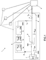
- Figure 1 shows a system 1 of four sensors realized as microphones 2 and a remote signal analyzer 3, wherein one of the microphones 2 is shown in detail. All four microphones 2 are connected with a coax-cable 4 that comprises two wires, a signal wire 5 and a shield wire 6. Other two wire cables could be used as well as interface between the microphones 2 and the analyzer 3.
- Each of the microphones 2 comprises an acoustic sensor 7, that is built as acoustic transducer with a membrane to measure the physical parameter of noise or sound.
- Microphones 2 of system 1 may for instance be attached on the surface of a wing of a test airplane to sense turbulences and to improve the surface of the wing.
- Analyzer 3 is built to transfer a constant input current I in over signal wire 5 to the microphones 2.
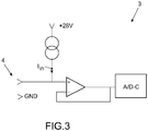
- Figure 3 shows that part of analyzer 3 that generates the constant input current I in and amplifies the audio signal U aud received from microphone 2.
- Microphones 2 comprise a polarization voltage supply 8 connected to signal wire 5 to generate a polarization voltage U pol at a capacity 10 of an acoustic sensor 7 and a pre-amplifier 9 of the microphones 2.
- the pre-amplifier 9 is used to amplify an audio signal generated by the acoustic sensor 7, which is built with a membrane that forms the capacity 10 that changes with the amount of noise or sound at the membrane.
- Microphone 2 is capsuled with a housing and needs to be polarized by the high precision low noise polarization voltage U pol of about 200V, which thereby transforms the change in capacity 10 direct proportional into a high impedance voltage signal to be fed to the pre-amplifier 9.
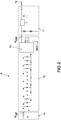
- Polarization voltage supply 8 comprises a transformation stage 11 to transform a partial part of the constant input current I in on signal wire 5, shown in figures 1 and 2 as transformation current I T , from the remote signal analyzer 3 into a stabilized output voltage U stab with a first voltage level, which could be in the rage of e.g. 5V to 15V. Transformation stage 11 could be realized by an integrated precision power supply circuit available on the market as shown in figure 2 .
- Polarization voltage supply 8 furthermore comprises a voltage increaser stage 12 to increase the voltage level of the high precision stabilized output voltage U stab into an increased output voltage U high with a second voltage level, which could be in the rage of e.g. 20V to 300V and typically is about 200V.
- Voltage increaser stage 12 is realized as charge pump circuit known to a man skilled in the art that consists of a row of capacitors and diodes driven by a switching circuit and could be integrated in C-MOS technology. Such a charge pump circuit with an oscillator 13 is shown in figure 2 .
- Polarization voltage supply 8 furthermore comprises a noise reduction stage 14, as shown in figure 2 , to provide a polarization voltage sourced through resistance R to the microphone 7, which could be in the range of e.g. 10 to 50 G ⁇ and typically is 20 G ⁇ .
- the polarization voltage U pol is used to polarize the un-polarized microphone 2, thereby transforming the change in capacity direct proportional into a voltage signal. This provides that advantage that although only a two wire interface is used between microphones 2 and analyzer 3 an un-polarized microphones 2 may be used.
- the sequence of the transformation stage 11 and the voltage increaser stage 12 could be exchanged. This means that a voltage generated from the partial part of the constant input current I in would first be stabilized and then increased and afterwards processed in the noise reduction stage 14. In another embodiment both stages would be combined and processed in one stage. This sequence of generating the polarization voltage U pol would lead to the same advantages as for the embodiment shown in figures 1 to 3 .
Landscapes
- Physics & Mathematics (AREA)
- Engineering & Computer Science (AREA)
- Acoustics & Sound (AREA)
- Signal Processing (AREA)
- Circuit For Audible Band Transducer (AREA)
Claims (5)
- System (1) aus mindestens einem Mikrofon (2) und einem Femsignalanalysator (3), der mit nur zwei Drähten (5, 6) mit dem Mikrofon (2) verbunden ist, um ein Audiosignal (Uaud) zurück zum Analysator zu übertragen und um einen konstanten Eingangsstrom (Iin) auf einem der Drähte (5) vom Analysator (3) zu empfangen,
wobei das Mikrofon (2) einen akustischen Sensor (7) und einen Vorverstärker (9), der mit dem konstanten Eingangsstrom (Iin) angetrieben wird, umfasst, um das Audiosignal (Uaud) von dem akustischen Sensor (7), das zum Analysator (3) über die zwei Drähte (5, 6) zurück übertragen wird, zu verstärken, dadurch gekennzeichnet, dass das Mikrofon (2) eine Polarisationsspannungsversorgung (8) umfasst, die mit den zwei Drähten (5, 6) verbunden ist, um das Mikrofon (10) zu polarisieren, wobei die Polarisationsspannungsversorgung (8) umfasst:eine Transformationsstufe (11), um einen Teil des konstanten Eingangsstroms (Iin) auf dem einen Draht (5) von dem Femsignalanalysator (3) in eine Ausgangsspannung (Ustab) mit einem ersten Spannungspegel zu transformieren, undeine Spannungsübersetzungsstufe (12), um den Spannungspegel der Ausgangsspannung (Ustab) in eine übersetzte Ausgangsspannung (Uhigh) mit einem zweiten Spannungspegel zu übersetzen, undeine Rauschunterdrückungsstufe (13), um dem akustischen Sensor (7) eine Polarisationsspannung (Upol) bereitzustellen. - System (1) gemäß Anspruch 1, wobei die Polarisationsspannung (Upol) durch einen Widerstand (R) zu einer als akustischer Sensor verwendeten Mikrofonkapsel gelagert wird.
- System gemäß Anspruch 1 oder 2, wobei die Transformationsstufe (11) als eine integrierte Schaltung ausgeführt ist.
- System (1) gemäß einem der Ansprüche 1 bis 3, wobei die Spannungsübersetzungsstufe (12) als eine Ladepumpschaltung ausgeführt ist, die aus einer Reihe von Kondensatoren und Dioden besteht, die durch einen Schaltkreis angetrieben werden.
- System (1) gemäß einem der Ansprüche 1 bis 4, wobei die Rauschunterdrückungsstufe (13) als ein RC-Filter ausgeführt ist.
Priority Applications (3)
| Application Number | Priority Date | Filing Date | Title |
|---|---|---|---|
| DK17190512.8T DK3454568T3 (da) | 2017-09-12 | 2017-09-12 | Mikrofon-forforstærker med polariseringsspændingsforsyning |
| EP17190512.8A EP3454568B1 (de) | 2017-09-12 | 2017-09-12 | Mikrofonvorverstärker mit polarisationsspannungsversorgung |
| PL17190512T PL3454568T3 (pl) | 2017-09-12 | 2017-09-12 | Przedwzmacniacz do mikrofonu ze źródłem napięcia polaryzacji |
Applications Claiming Priority (1)
| Application Number | Priority Date | Filing Date | Title |
|---|---|---|---|
| EP17190512.8A EP3454568B1 (de) | 2017-09-12 | 2017-09-12 | Mikrofonvorverstärker mit polarisationsspannungsversorgung |
Publications (2)
| Publication Number | Publication Date |
|---|---|
| EP3454568A1 EP3454568A1 (de) | 2019-03-13 |
| EP3454568B1 true EP3454568B1 (de) | 2020-10-28 |
Family
ID=59858567
Family Applications (1)
| Application Number | Title | Priority Date | Filing Date |
|---|---|---|---|
| EP17190512.8A Active EP3454568B1 (de) | 2017-09-12 | 2017-09-12 | Mikrofonvorverstärker mit polarisationsspannungsversorgung |
Country Status (3)
| Country | Link |
|---|---|
| EP (1) | EP3454568B1 (de) |
| DK (1) | DK3454568T3 (de) |
| PL (1) | PL3454568T3 (de) |
Cited By (1)
| Publication number | Priority date | Publication date | Assignee | Title |
|---|---|---|---|---|
| EP4354728A1 (de) | 2022-10-14 | 2024-04-17 | Centrum Astronomiczne im. Mikolaja Kopernika Polskiej Akademii Nauk | Vorverstärker für ein im infraschallfrequenzbereich arbeitendes kapazitatormikrofon |
Family Cites Families (4)
| Publication number | Priority date | Publication date | Assignee | Title |
|---|---|---|---|---|
| US5377273A (en) * | 1992-03-26 | 1994-12-27 | Hewlett-Packard Company | Batteryless power supply for transducers |
| US7835531B2 (en) * | 2004-03-30 | 2010-11-16 | Akg Acoustics Gmbh | Microphone system |
| US9253569B2 (en) * | 2013-12-20 | 2016-02-02 | Infineon Technologies Ag | System and method for a cancelation circuit |
| CN105072241B (zh) * | 2015-07-31 | 2018-01-19 | 合肥赛为智能有限公司 | 一种对讲系统隔离变压器消侧音电路 |
-
2017
- 2017-09-12 DK DK17190512.8T patent/DK3454568T3/da active
- 2017-09-12 PL PL17190512T patent/PL3454568T3/pl unknown
- 2017-09-12 EP EP17190512.8A patent/EP3454568B1/de active Active
Cited By (1)
| Publication number | Priority date | Publication date | Assignee | Title |
|---|---|---|---|---|
| EP4354728A1 (de) | 2022-10-14 | 2024-04-17 | Centrum Astronomiczne im. Mikolaja Kopernika Polskiej Akademii Nauk | Vorverstärker für ein im infraschallfrequenzbereich arbeitendes kapazitatormikrofon |
Also Published As
| Publication number | Publication date |
|---|---|
| PL3454568T3 (pl) | 2021-05-04 |
| DK3454568T3 (da) | 2021-01-11 |
| EP3454568A1 (de) | 2019-03-13 |
Similar Documents
| Publication | Publication Date | Title |
|---|---|---|
| KR101524900B1 (ko) | 집적된 자체 테스트 회로를 구비하는 마이크 어셈블리 | |
| US8179121B2 (en) | Bridge sensor with collocated electronics and two-wire interface | |
| CN102027339B (zh) | 用于传感器及放大器的原位测试的全功能测试 | |
| US10082021B2 (en) | Azimuthally acoustic while drilling signal receiving transducer encapsulating apparatus | |
| KR20110040359A (ko) | 휴대용 단말기에서 이어폰 인식 회로 장치 | |
| US10440482B2 (en) | Biasing of electromechanical systems transducer with alternating-current voltage waveform | |
| CN110431383B (zh) | 用于校准电容传感器接口的装置和方法 | |
| EP3454568B1 (de) | Mikrofonvorverstärker mit polarisationsspannungsversorgung | |
| US8280694B2 (en) | Constant current power source electronics for a sensor | |
| US10571436B2 (en) | Transducer array CMUT element biasing | |
| US20180028150A1 (en) | Ultrasonic probe and subject information acquisition apparatus | |
| HK40006229B (en) | Microphone pre-amplifier with polarization voltage supply | |
| HK40006229A (en) | Microphone pre-amplifier with polarization voltage supply | |
| WO2016084220A9 (ja) | 超音波プローブ、及びそれを備えた情報取得装置 | |
| CN110514869A (zh) | 利用双线接口来测量特定量的电子装置 | |
| US9534973B2 (en) | Capacitive static and dynamic sensor | |
| US20170038247A1 (en) | Two-Wire Electronics Interface Sensor With Integrated Mechanical Transducing And Temperature Monitoring Capability | |
| CN204556849U (zh) | 测耦检波器 | |
| US9955273B2 (en) | Microphone assembly and method for determining parameters of a transducer in a microphone assembly | |
| EP1961260B1 (de) | Vorrichtung zur messung eines akustischen drucks | |
| US9451368B2 (en) | Feedback scan for hearing aid | |
| KR101578375B1 (ko) | 오디오 입출력 포트에 장착할 수 있는 외장형 멀티 미터 장치, 모바일 멀티 미터 시스템 및 외장형 멀티 미터 장치 구동 방법 | |
| RU2392767C1 (ru) | Гидрофон | |
| US12025633B2 (en) | Two-wire interface reference accelerometer with integrated mechanical transducing and self-calibration capability | |
| EP4354728A1 (de) | Vorverstärker für ein im infraschallfrequenzbereich arbeitendes kapazitatormikrofon |
Legal Events
| Date | Code | Title | Description |
|---|---|---|---|
| PUAI | Public reference made under article 153(3) epc to a published international application that has entered the european phase |
Free format text: ORIGINAL CODE: 0009012 |
|
| STAA | Information on the status of an ep patent application or granted ep patent |
Free format text: STATUS: THE APPLICATION HAS BEEN PUBLISHED |
|
| AK | Designated contracting states |
Kind code of ref document: A1 Designated state(s): AL AT BE BG CH CY CZ DE DK EE ES FI FR GB GR HR HU IE IS IT LI LT LU LV MC MK MT NL NO PL PT RO RS SE SI SK SM TR |
|
| AX | Request for extension of the european patent |
Extension state: BA ME |
|
| STAA | Information on the status of an ep patent application or granted ep patent |
Free format text: STATUS: REQUEST FOR EXAMINATION WAS MADE |
|
| 17P | Request for examination filed |
Effective date: 20190813 |
|
| RBV | Designated contracting states (corrected) |
Designated state(s): AL AT BE BG CH CY CZ DE DK EE ES FI FR GB GR HR HU IE IS IT LI LT LU LV MC MK MT NL NO PL PT RO RS SE SI SK SM TR |
|
| REG | Reference to a national code |
Ref country code: HK Ref legal event code: DE Ref document number: 40006229 Country of ref document: HK |
|
| GRAP | Despatch of communication of intention to grant a patent |
Free format text: ORIGINAL CODE: EPIDOSNIGR1 |
|
| STAA | Information on the status of an ep patent application or granted ep patent |
Free format text: STATUS: GRANT OF PATENT IS INTENDED |
|
| INTG | Intention to grant announced |
Effective date: 20200630 |
|
| GRAS | Grant fee paid |
Free format text: ORIGINAL CODE: EPIDOSNIGR3 |
|
| GRAA | (expected) grant |
Free format text: ORIGINAL CODE: 0009210 |
|
| STAA | Information on the status of an ep patent application or granted ep patent |
Free format text: STATUS: THE PATENT HAS BEEN GRANTED |
|
| AK | Designated contracting states |
Kind code of ref document: B1 Designated state(s): AL AT BE BG CH CY CZ DE DK EE ES FI FR GB GR HR HU IE IS IT LI LT LU LV MC MK MT NL NO PL PT RO RS SE SI SK SM TR |
|
| REG | Reference to a national code |
Ref country code: GB Ref legal event code: FG4D |
|
| REG | Reference to a national code |
Ref country code: CH Ref legal event code: EP |
|
| REG | Reference to a national code |
Ref country code: AT Ref legal event code: REF Ref document number: 1329462 Country of ref document: AT Kind code of ref document: T Effective date: 20201115 |
|
| REG | Reference to a national code |
Ref country code: DE Ref legal event code: R096 Ref document number: 602017026222 Country of ref document: DE |
|
| REG | Reference to a national code |
Ref country code: IE Ref legal event code: FG4D |
|
| REG | Reference to a national code |
Ref country code: DK Ref legal event code: T3 Effective date: 20210106 |
|
| REG | Reference to a national code |
Ref country code: DE Ref legal event code: R082 Ref document number: 602017026222 Country of ref document: DE |
|
| REG | Reference to a national code |
Ref country code: SE Ref legal event code: TRGR |
|
| REG | Reference to a national code |
Ref country code: AT Ref legal event code: MK05 Ref document number: 1329462 Country of ref document: AT Kind code of ref document: T Effective date: 20201028 |
|
| REG | Reference to a national code |
Ref country code: NO Ref legal event code: T2 Effective date: 20201028 |
|
| REG | Reference to a national code |
Ref country code: NL Ref legal event code: MP Effective date: 20201028 |
|
| PG25 | Lapsed in a contracting state [announced via postgrant information from national office to epo] |
Ref country code: RS Free format text: LAPSE BECAUSE OF FAILURE TO SUBMIT A TRANSLATION OF THE DESCRIPTION OR TO PAY THE FEE WITHIN THE PRESCRIBED TIME-LIMIT Effective date: 20201028 Ref country code: PT Free format text: LAPSE BECAUSE OF FAILURE TO SUBMIT A TRANSLATION OF THE DESCRIPTION OR TO PAY THE FEE WITHIN THE PRESCRIBED TIME-LIMIT Effective date: 20210301 Ref country code: FI Free format text: LAPSE BECAUSE OF FAILURE TO SUBMIT A TRANSLATION OF THE DESCRIPTION OR TO PAY THE FEE WITHIN THE PRESCRIBED TIME-LIMIT Effective date: 20201028 Ref country code: GR Free format text: LAPSE BECAUSE OF FAILURE TO SUBMIT A TRANSLATION OF THE DESCRIPTION OR TO PAY THE FEE WITHIN THE PRESCRIBED TIME-LIMIT Effective date: 20210129 |
|
| REG | Reference to a national code |
Ref country code: LT Ref legal event code: MG4D |
|
| PG25 | Lapsed in a contracting state [announced via postgrant information from national office to epo] |
Ref country code: ES Free format text: LAPSE BECAUSE OF FAILURE TO SUBMIT A TRANSLATION OF THE DESCRIPTION OR TO PAY THE FEE WITHIN THE PRESCRIBED TIME-LIMIT Effective date: 20201028 Ref country code: AT Free format text: LAPSE BECAUSE OF FAILURE TO SUBMIT A TRANSLATION OF THE DESCRIPTION OR TO PAY THE FEE WITHIN THE PRESCRIBED TIME-LIMIT Effective date: 20201028 Ref country code: BG Free format text: LAPSE BECAUSE OF FAILURE TO SUBMIT A TRANSLATION OF THE DESCRIPTION OR TO PAY THE FEE WITHIN THE PRESCRIBED TIME-LIMIT Effective date: 20210128 Ref country code: LV Free format text: LAPSE BECAUSE OF FAILURE TO SUBMIT A TRANSLATION OF THE DESCRIPTION OR TO PAY THE FEE WITHIN THE PRESCRIBED TIME-LIMIT Effective date: 20201028 Ref country code: IS Free format text: LAPSE BECAUSE OF FAILURE TO SUBMIT A TRANSLATION OF THE DESCRIPTION OR TO PAY THE FEE WITHIN THE PRESCRIBED TIME-LIMIT Effective date: 20210228 |
|
| PG25 | Lapsed in a contracting state [announced via postgrant information from national office to epo] |
Ref country code: HR Free format text: LAPSE BECAUSE OF FAILURE TO SUBMIT A TRANSLATION OF THE DESCRIPTION OR TO PAY THE FEE WITHIN THE PRESCRIBED TIME-LIMIT Effective date: 20201028 Ref country code: NL Free format text: LAPSE BECAUSE OF FAILURE TO SUBMIT A TRANSLATION OF THE DESCRIPTION OR TO PAY THE FEE WITHIN THE PRESCRIBED TIME-LIMIT Effective date: 20201028 |
|
| REG | Reference to a national code |
Ref country code: DE Ref legal event code: R097 Ref document number: 602017026222 Country of ref document: DE |
|
| PG25 | Lapsed in a contracting state [announced via postgrant information from national office to epo] |
Ref country code: LT Free format text: LAPSE BECAUSE OF FAILURE TO SUBMIT A TRANSLATION OF THE DESCRIPTION OR TO PAY THE FEE WITHIN THE PRESCRIBED TIME-LIMIT Effective date: 20201028 Ref country code: SM Free format text: LAPSE BECAUSE OF FAILURE TO SUBMIT A TRANSLATION OF THE DESCRIPTION OR TO PAY THE FEE WITHIN THE PRESCRIBED TIME-LIMIT Effective date: 20201028 Ref country code: EE Free format text: LAPSE BECAUSE OF FAILURE TO SUBMIT A TRANSLATION OF THE DESCRIPTION OR TO PAY THE FEE WITHIN THE PRESCRIBED TIME-LIMIT Effective date: 20201028 Ref country code: CZ Free format text: LAPSE BECAUSE OF FAILURE TO SUBMIT A TRANSLATION OF THE DESCRIPTION OR TO PAY THE FEE WITHIN THE PRESCRIBED TIME-LIMIT Effective date: 20201028 Ref country code: RO Free format text: LAPSE BECAUSE OF FAILURE TO SUBMIT A TRANSLATION OF THE DESCRIPTION OR TO PAY THE FEE WITHIN THE PRESCRIBED TIME-LIMIT Effective date: 20201028 Ref country code: SK Free format text: LAPSE BECAUSE OF FAILURE TO SUBMIT A TRANSLATION OF THE DESCRIPTION OR TO PAY THE FEE WITHIN THE PRESCRIBED TIME-LIMIT Effective date: 20201028 |
|
| PLBE | No opposition filed within time limit |
Free format text: ORIGINAL CODE: 0009261 |
|
| STAA | Information on the status of an ep patent application or granted ep patent |
Free format text: STATUS: NO OPPOSITION FILED WITHIN TIME LIMIT |
|
| 26N | No opposition filed |
Effective date: 20210729 |
|
| PG25 | Lapsed in a contracting state [announced via postgrant information from national office to epo] |
Ref country code: AL Free format text: LAPSE BECAUSE OF FAILURE TO SUBMIT A TRANSLATION OF THE DESCRIPTION OR TO PAY THE FEE WITHIN THE PRESCRIBED TIME-LIMIT Effective date: 20201028 Ref country code: IT Free format text: LAPSE BECAUSE OF FAILURE TO SUBMIT A TRANSLATION OF THE DESCRIPTION OR TO PAY THE FEE WITHIN THE PRESCRIBED TIME-LIMIT Effective date: 20201028 |
|
| PG25 | Lapsed in a contracting state [announced via postgrant information from national office to epo] |
Ref country code: SI Free format text: LAPSE BECAUSE OF FAILURE TO SUBMIT A TRANSLATION OF THE DESCRIPTION OR TO PAY THE FEE WITHIN THE PRESCRIBED TIME-LIMIT Effective date: 20201028 |
|
| REG | Reference to a national code |
Ref country code: CH Ref legal event code: PL |
|
| REG | Reference to a national code |
Ref country code: BE Ref legal event code: MM Effective date: 20210930 |
|
| PG25 | Lapsed in a contracting state [announced via postgrant information from national office to epo] |
Ref country code: IS Free format text: LAPSE BECAUSE OF FAILURE TO SUBMIT A TRANSLATION OF THE DESCRIPTION OR TO PAY THE FEE WITHIN THE PRESCRIBED TIME-LIMIT Effective date: 20210228 Ref country code: MC Free format text: LAPSE BECAUSE OF FAILURE TO SUBMIT A TRANSLATION OF THE DESCRIPTION OR TO PAY THE FEE WITHIN THE PRESCRIBED TIME-LIMIT Effective date: 20201028 |
|
| PG25 | Lapsed in a contracting state [announced via postgrant information from national office to epo] |
Ref country code: LU Free format text: LAPSE BECAUSE OF NON-PAYMENT OF DUE FEES Effective date: 20210912 Ref country code: IE Free format text: LAPSE BECAUSE OF NON-PAYMENT OF DUE FEES Effective date: 20210912 Ref country code: BE Free format text: LAPSE BECAUSE OF NON-PAYMENT OF DUE FEES Effective date: 20210930 |
|
| PG25 | Lapsed in a contracting state [announced via postgrant information from national office to epo] |
Ref country code: LI Free format text: LAPSE BECAUSE OF NON-PAYMENT OF DUE FEES Effective date: 20210930 Ref country code: CH Free format text: LAPSE BECAUSE OF NON-PAYMENT OF DUE FEES Effective date: 20210930 |
|
| PG25 | Lapsed in a contracting state [announced via postgrant information from national office to epo] |
Ref country code: CY Free format text: LAPSE BECAUSE OF FAILURE TO SUBMIT A TRANSLATION OF THE DESCRIPTION OR TO PAY THE FEE WITHIN THE PRESCRIBED TIME-LIMIT Effective date: 20201028 |
|
| PG25 | Lapsed in a contracting state [announced via postgrant information from national office to epo] |
Ref country code: HU Free format text: LAPSE BECAUSE OF FAILURE TO SUBMIT A TRANSLATION OF THE DESCRIPTION OR TO PAY THE FEE WITHIN THE PRESCRIBED TIME-LIMIT; INVALID AB INITIO Effective date: 20170912 |
|
| PG25 | Lapsed in a contracting state [announced via postgrant information from national office to epo] |
Ref country code: MK Free format text: LAPSE BECAUSE OF FAILURE TO SUBMIT A TRANSLATION OF THE DESCRIPTION OR TO PAY THE FEE WITHIN THE PRESCRIBED TIME-LIMIT Effective date: 20201028 |
|
| PG25 | Lapsed in a contracting state [announced via postgrant information from national office to epo] |
Ref country code: TR Free format text: LAPSE BECAUSE OF FAILURE TO SUBMIT A TRANSLATION OF THE DESCRIPTION OR TO PAY THE FEE WITHIN THE PRESCRIBED TIME-LIMIT Effective date: 20201028 |
|
| PG25 | Lapsed in a contracting state [announced via postgrant information from national office to epo] |
Ref country code: MT Free format text: LAPSE BECAUSE OF FAILURE TO SUBMIT A TRANSLATION OF THE DESCRIPTION OR TO PAY THE FEE WITHIN THE PRESCRIBED TIME-LIMIT Effective date: 20201028 |
|
| P01 | Opt-out of the competence of the unified patent court (upc) registered |
Free format text: CASE NUMBER: APP_30665/2025 Effective date: 20250626 |
|
| PGFP | Annual fee paid to national office [announced via postgrant information from national office to epo] |
Ref country code: DK Payment date: 20250922 Year of fee payment: 9 Ref country code: DE Payment date: 20250919 Year of fee payment: 9 |
|
| PGFP | Annual fee paid to national office [announced via postgrant information from national office to epo] |
Ref country code: NO Payment date: 20250919 Year of fee payment: 9 |
|
| PGFP | Annual fee paid to national office [announced via postgrant information from national office to epo] |
Ref country code: PL Payment date: 20250901 Year of fee payment: 9 |
|
| PGFP | Annual fee paid to national office [announced via postgrant information from national office to epo] |
Ref country code: GB Payment date: 20250923 Year of fee payment: 9 |
|
| PGFP | Annual fee paid to national office [announced via postgrant information from national office to epo] |
Ref country code: FR Payment date: 20250924 Year of fee payment: 9 |
|
| PGFP | Annual fee paid to national office [announced via postgrant information from national office to epo] |
Ref country code: SE Payment date: 20250922 Year of fee payment: 9 |