EP3454456A1 - Pole piece for a torque motor - Google Patents
Pole piece for a torque motor Download PDFInfo
- Publication number
- EP3454456A1 EP3454456A1 EP17461601.1A EP17461601A EP3454456A1 EP 3454456 A1 EP3454456 A1 EP 3454456A1 EP 17461601 A EP17461601 A EP 17461601A EP 3454456 A1 EP3454456 A1 EP 3454456A1
- Authority
- EP
- European Patent Office
- Prior art keywords
- section
- piece
- pole
- pole piece
- holes
- Prior art date
- Legal status (The legal status is an assumption and is not a legal conclusion. Google has not performed a legal analysis and makes no representation as to the accuracy of the status listed.)
- Granted
Links
Images




Classifications
-
- H—ELECTRICITY
- H02—GENERATION; CONVERSION OR DISTRIBUTION OF ELECTRIC POWER
- H02K—DYNAMO-ELECTRIC MACHINES
- H02K26/00—Machines adapted to function as torque motors, i.e. to exert a torque when stalled
-
- H—ELECTRICITY
- H02—GENERATION; CONVERSION OR DISTRIBUTION OF ELECTRIC POWER
- H02K—DYNAMO-ELECTRIC MACHINES
- H02K1/00—Details of the magnetic circuit
- H02K1/06—Details of the magnetic circuit characterised by the shape, form or construction
- H02K1/08—Salient poles
-
- H—ELECTRICITY
- H02—GENERATION; CONVERSION OR DISTRIBUTION OF ELECTRIC POWER
- H02K—DYNAMO-ELECTRIC MACHINES
- H02K1/00—Details of the magnetic circuit
- H02K1/06—Details of the magnetic circuit characterised by the shape, form or construction
- H02K1/12—Stationary parts of the magnetic circuit
- H02K1/17—Stator cores with permanent magnets
-
- H—ELECTRICITY
- H02—GENERATION; CONVERSION OR DISTRIBUTION OF ELECTRIC POWER
- H02K—DYNAMO-ELECTRIC MACHINES
- H02K1/00—Details of the magnetic circuit
- H02K1/06—Details of the magnetic circuit characterised by the shape, form or construction
- H02K1/12—Stationary parts of the magnetic circuit
- H02K1/18—Means for mounting or fastening magnetic stationary parts on to, or to, the stator structures
-
- H—ELECTRICITY
- H02—GENERATION; CONVERSION OR DISTRIBUTION OF ELECTRIC POWER
- H02K—DYNAMO-ELECTRIC MACHINES
- H02K15/00—Processes or apparatus specially adapted for manufacturing, assembling, maintaining or repairing of dynamo-electric machines
-
- H—ELECTRICITY
- H02—GENERATION; CONVERSION OR DISTRIBUTION OF ELECTRIC POWER
- H02K—DYNAMO-ELECTRIC MACHINES
- H02K15/00—Processes or apparatus specially adapted for manufacturing, assembling, maintaining or repairing of dynamo-electric machines
- H02K15/02—Processes or apparatus specially adapted for manufacturing, assembling, maintaining or repairing of dynamo-electric machines of stator or rotor bodies
- H02K15/03—Processes or apparatus specially adapted for manufacturing, assembling, maintaining or repairing of dynamo-electric machines of stator or rotor bodies having permanent magnets
-
- H—ELECTRICITY
- H02—GENERATION; CONVERSION OR DISTRIBUTION OF ELECTRIC POWER
- H02K—DYNAMO-ELECTRIC MACHINES
- H02K15/00—Processes or apparatus specially adapted for manufacturing, assembling, maintaining or repairing of dynamo-electric machines
- H02K15/16—Centring rotors within the stators
-
- F—MECHANICAL ENGINEERING; LIGHTING; HEATING; WEAPONS; BLASTING
- F15—FLUID-PRESSURE ACTUATORS; HYDRAULICS OR PNEUMATICS IN GENERAL
- F15B—SYSTEMS ACTING BY MEANS OF FLUIDS IN GENERAL; FLUID-PRESSURE ACTUATORS, e.g. SERVOMOTORS; DETAILS OF FLUID-PRESSURE SYSTEMS, NOT OTHERWISE PROVIDED FOR
- F15B13/00—Details of servomotor systems ; Valves for servomotor systems
- F15B13/02—Fluid distribution or supply devices characterised by their adaptation to the control of servomotors
- F15B13/04—Fluid distribution or supply devices characterised by their adaptation to the control of servomotors for use with a single servomotor
- F15B13/042—Fluid distribution or supply devices characterised by their adaptation to the control of servomotors for use with a single servomotor operated by fluid pressure
- F15B13/043—Fluid distribution or supply devices characterised by their adaptation to the control of servomotors for use with a single servomotor operated by fluid pressure with electrically-controlled pilot valves
- F15B13/0436—Fluid distribution or supply devices characterised by their adaptation to the control of servomotors for use with a single servomotor operated by fluid pressure with electrically-controlled pilot valves the pilot valves being of the steerable jet type
-
- H—ELECTRICITY
- H02—GENERATION; CONVERSION OR DISTRIBUTION OF ELECTRIC POWER
- H02K—DYNAMO-ELECTRIC MACHINES
- H02K2201/00—Specific aspects not provided for in the other groups of this subclass relating to the magnetic circuits
- H02K2201/03—Machines characterised by aspects of the air-gap between rotor and stator
Definitions
- the present disclosure relates generally to a pole piece for a torque motor, and more generally to a torque motor incorporating the pole piece and methods of manufacturing a pole piece for a torque motor.
- Torque motors are known in the art and are configured to produce a torque in order to rotate or move a shaft (e.g., a jet pipe) so as to operate a valve, for example a valve used in a direct drive or pneumatic field, such as an electrohydraulic servo-valve.
- a shaft e.g., a jet pipe
- a valve for example a valve used in a direct drive or pneumatic field, such as an electrohydraulic servo-valve.
- FIG. 1A An example of a torque motor 10 is shown in Fig. 1A (which is provided for illustrative purposes only), and comprises a lower pole piece 12 and an upper pole piece 14, two sets of coils 16, an armature 18 that is pivotally located within the structure of the torque motor 10.
- the pivoting armature 18 is connected to a shaft 20, a lower end of which (not shown) is configured to move (e.g., left and right) upon rotation of the armature 18.
- the movement of the lower end of the shaft 20 e.g., jet pipe
- the components that are used to create the magnetic field around the armature 18 must be manufactured to a high precision, and such that the clearances between the various magnetic parts (e.g., the lower and upper pole pieces 12, 14, the coils 16 and the armature 18) are as small as possible.
- the lower pole piece 12 may be opened or divided into two separate parts 12a, 12b, and an additional part 13, called a magnetic shunt, may be used to connect the separate parts 12a, 12b of the lower pole piece 12 when assembling the torque motor 10.
- the geometrical features associated with the connections between the separate parts 12a, 12b of the lower pole piece 12 and the magnetic shunt 13 have to be manufactured with a high precision, but also to allow for the change of the material properties caused by stresses in use. This means, for example, that an interference or press fit may not be used due to potential changes of the material properties; therefore, even with high precision methods that use tight tolerances, there will typically be gaps present between these parts.
- a setting shim 11 may be provided in order to connect the various parts of the torque motor 10 to a housing 22.
- a component 23 may be provided that forms a combined magnetic shunt and setting shim. In this embodiment, the same issues may occur, in that the various components must be manufactured with tight tolerances, but may not be provided with an interference or press fit.
- a pole-piece for a torque motor comprising a first section and a second section, wherein the first section is held in position with respect to the second section using one or more rigid members.
- a method of manufacturing a pole-piece for a torque motor comprising:
- the first section and the second section may be formed separate from each other, such that they may be two separate pieces.
- the first section may be configured to be brought into abutment or contact with the second section.
- the use of rigid members to hold the first section in position with respect to the second section may improve the magnetic characteristics of a pole-piece that is formed from separate sections. Furthermore, the use of rigid members can ease the manufacture and structure of the pole-piece.
- the pole-piece may further comprise one or more cavities, holes or apertures for locating the rigid members therein.
- the one or more rigid members may be located within said one or more cavities, holes or apertures to hold the first section in position with respect to the second section.
- the first section may be restricted against movement with respect to the second section.
- the one or more cavities, holes or apertures may comprise one or more holes extending from an opening in one of the first section and the second section through to the interior of the other of the first section and the second section.
- a rigid member may be inserted into each hole and/or may extend through the hole between the first section and the second section.
- Each hole may comprise a first hole portion that is located within the first section of the pole piece, and a second hole portion that is located within the second section of the pole piece.
- the first hole portion of each hole may align with the second hole portion of that hole to form the hole in the pole-piece.
- Each hole may extend from the second section of the lower pole piece and into the first section (e.g., an interior thereof) of the lower pole piece when the first section is abutted to the second section.
- the one or more cavities, holes or apertures may comprise one or more cavities (e.g., a depression or hollow space) in an outer surface of the pole piece, wherein each cavity may extend from the first section to the second section.
- a rigid member may be inserted into each cavity and/or may extend between the first section and the second section.
- Each cavity may comprise a first cavity portion that is located within the first section of the pole piece, and a second cavity portion that is located within the second section of the pole piece.
- the first cavity portion may align with the second cavity portion to form the cavity.
- the pole-piece may comprise or consist of a pair of said cavities, holes or apertures, for example a pair of said holes, a pair of said cavities, or a pair comprising one hole and one cavity as described above.
- each of said pairs may be located on opposed sides of a line bisecting the pole piece.
- each of said pairs may be located symmetrically on opposed sides of the line bisecting the pole piece.
- One or more abutment surfaces of the first section may be configured to abut one or more abutment surfaces of the second section when the first section is held in position with respect to the second section using the one or more rigid members, and the abutment surfaces form one or more lines of abutment in an outer surface of the pole piece, wherein each rigid member may extend through a line of abutment.
- a longitudinal axis of each rigid member may be at an angle with respect to the line of abutment through which it extends. The angle may be less than 90 degrees, and/or the angle may be between 10-80 degrees, for example between 20-70 degrees, or between 30-60 degrees. The angle may be about 45 degrees.
- the one or more rigid members may comprise a pair of pins, although any suitable type of rigid member may be used with any of the aspects and embodiments described herein.
- the rigid members may be disposed at an angle ( ⁇ ) with respect to each other.
- the angle may be between 30-150 degrees, for example 50-130 degrees, 70-110 degrees or 80-100 degrees.
- the angle may be about 90 degrees.
- the one or more rigid members may be configured to hold the first section in an abutting relationship with the second section, such that one or more abutment surfaces (137) of the first section (132) are configured to abut one or more abutment surfaces (139) of the second section (134) when the first section (132,132') is held in position with respect to the second section (134,134') using the one or more rigid members (150,150').
- the method described above may further comprise:
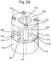
- Figs. 2A and 2B shows an embodiment of a torque motor 100 in accordance with the present disclosure in assembled form ( Fig. 2A ) and exploded form ( Fig. 2B ).
- the torque motor 100 sits on a housing 110 that may contain various components (not shown) for operating a valve and/or controlling fluid flow of various types, as is known in the art.
- the housing 110 may comprise an upper surface or platform 112 upon which the various components of the torque motor 100 are placed, which upper surface 112 comprises an aperture 114, through which may extend a shaft 120 of the torque motor 100.
- the shaft 120 may form part of, for example, a jet pipe assembly for use in an electrohydraulic servo-valve.
- the torque motor 100 may also be used in other applications such as a flapper - nozzle structure, a direct drive valve or pneumatic valve, or the like. A detailed description of such applications, e.g., a jet pipe assembly is not provided herein, since a skilled person will have adequate knowledge of the construction and function of such applications.
- a shim 118 may be disposed upon the upper surface 112 of the housing 110 and may be used for connecting the various components of the torque motor 100 to the housing 110, and allow easy adjustment thereof.
- the shim 118 also provides desired operational characteristics and stability of the torque motor 100.
- the torque motor 100 comprises a lower pole piece 130 that is split into two separate sections or portions 132 and 134, which will be described in more detail below.
- the torque motor 100 further comprises an upper pole piece 160 that may be formed as a single piece (e.g., in contrast to the lower pole piece 130).
- the lower pole piece 130 may form a substantially annular member in use.
- the upper pole piece 160 and the lower pole piece 130 may be connected to the housing 110 through the shim 118 via fasteners 170, which are configured to fasten these components to the housing 110.
- Spacers 172 may be provided, and configured to separate the upper pole piece 160 from the lower pole piece 130 when the fasteners 170 are fastened to the housing 110.
- the fasteners 170 are configured to extend through a plurality of (e.g., four) apertures 162 in the upper pole piece 160, as well as a plurality of (e.g., four) apertures 136 in the lower pole piece 130, and a plurality of (e.g., four) apertures 119 in the shim 118.
- the torque motor 100 comprises an armature 180, which is configured to pivot or rotate in use as is known in the art.
- the armature 180 is connected to the shaft 120, such that a lower end of the shaft (not shown) may be configured to move (e.g., side-to-side) upon rotation of the armature 180.
- the movement of the lower end of the shaft 120 may be used to operate a valve and/or control fluid flow of various types, and other applications, as discussed herein.
- armature 180 Surrounding the armature 180 are a pair of electromagnetic coils 185, which may be energised in use to cause the armature 180 to pivot or rotate to actuate the torque motor 100.
- the coils 185 are disposed so that opposite arm portions of the armature 180 extend through the coils 185. When an electrical signal is applied to the coils 185, the magnetic forces generated cause the armature 180 to pivot or rotate as aforesaid.
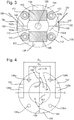
- Fig. 3 shows the lower pole piece 130 as comprising a first portion 132 and a second portion 134 that abut each other, wherein one or more abutment surfaces 137 (e.g., two, as shown in Fig. 4 ) of the first portion 132 are configured to contact one or more abutment surfaces 139 (e.g., two, as shown in Fig. 4 ) of the second portion 134, so as to form one or more (e.g., two) lines of abutment 140 (or lines of contact) that extend along an outer surface of the pole-piece 130.
- abutment may be used to indicate that, although the first portion 132 and the second portion 134 may touch along their abutment surfaces, they may also be merely adjacent to each other along the line.
- each hole 152 comprises a first hole portion 152a that is located within the first portion 132 of the pole piece 130, and a second hole portion 152b that is located within the second portion 134 of the pole piece 130.
- Each hole 152 extends from the second portion 134 of the lower pole piece 130 and into the first portion 132 (e.g., an interior thereof) of the lower pole piece 130 when the first portion 132 is abutted to the second portion 134.
- Notches 154 may be provided in the circumferential edge of the second portion 134, which notches 154 comprise the entrance to the passages 152, such that each hole 152 extends from an entrance at the notch 154, through the second hole portion 152b (which is formed in the interior of the second portion 134) and then through the first hole portion 152a (which is formed in the interior of the first portion 132).
- the lower pole piece 130 may also comprise raised portions 138 located at opposite ends of the lower pole piece 130, and configured to be located below the axial ends of the armature 180 in use.
- Fig. 4 shows the lower pole piece 130 in isolation and comprising the first portion 132 and the second portion 134.
- the lower pole piece 130 is shown immediately after it has been cut from a single piece of material.
- the first portion 132 is separated from the second portion 134 by two cutting lines 140.
- the cutting means that the first portion 132 is separated from the second portion 134 by a gap G, wherein the gap G has a width A corresponding to the width of material removed from the lower pole piece 130 during cutting.
- the notches 154 may be formed in the second portion 134 prior to or, in some embodiments, after cutting.
- the cutting lines 140 may be referred to as lines of abutment 140 once the two portions 132, 134 are brought into contact (e.g., in use), since the lines correspond to the abutment surfaces 137, 139 of the first and second portions 132, 134, respectively.
- the two separate portions 132, 134 may not be formed by cutting, but simply manufactured from separate pieces of material.
- the second portion 134 may be shifted from the first portion 132 by a distance A that corresponds to the width A of the gap G.
- the distance A may be the distance that the second section 134 will need to move to contact the first section 132 after the cutting step, and may be calculated or determined prior to cutting.
- An XY axis may be defined, as shown in Figs. 4 and 5 , wherein the X direction may correspond to the longitudinal axis of the armature 180 in use, and the Y direction may be perpendicular to the longitudinal axis of the armature 180.
- the X and Y axes may intersect at a centrepoint 131 of the lower pole piece 130 and may be perpendicular to each other.
- Fig. 5 shows the lower pole piece 130 after this shift.
- the holes 136b of the second portion 134 may be located a distance D 1 from the holes 136a of the first portion 132 (e.g., in the X direction), and the distance D 1 may be equal to a first distance d 1 +A.
- the holes 136b of the second portion 134 may be located a distance D 2 from the holes 136a of the first portion 132 (e.g., in the X direction), and the distance D 2 may be equal to a second distance d 1 , which is equal to the first distance minus the width A of the gap G.
- the raised portion 138b of the second portion 134 may be located a distance D 3 from the raised portion 138a of the first portion 132 (e.g., in the X direction), and the distance D 3 may be equal to a third distance d 2 +A.
- the raised portion 138b of the second portion 134 may be located a distance D 4 from the raised portion 138a of the first portion 132 (e.g., in the X direction), and the distance D 4 may be equal to a fourth distance d 2 , which is equal to the third distance minus the width A of the cutting lines 140.
- the lines of abutment 140 may be orientated parallel or perpendicular to the X and Y axes (e.g., the longitudinal axis of the armature 180 in use), as shown in Figs. 4 and 5 .
- the lines of abutment 140 (and/or cutting lines) may be parallel to one or other of the X and Y axes throughout their entire length.
- lines of abutment 140 are shown as being parallel or perpendicular to the longitudinal axis of the armature 180, various embodiments are contemplated in which the lines of abutment 140 may be slightly different, for example not at a right angle with respect to the X or Y axes, whilst still providing technical effects not achieved by conventional arrangements.
- each line of abutment 140 may be substantially the same on either side of the lower pole piece 130 (e.g., on either side of the X axis).
- Each line of abutment 140 may, additionally or alternatively, be substantially straight (e.g., when moving or travelling along the line of abutment 140 from one end to the other).
- the lines of abutment 140 may have translational symmetry with each other.
- the lines of abutment 140 may correspond to the abutment surfaces 137. 130 of the first and second portions 132, 134, respectively.
- the shape and/or orientation of the abutment surfaces 137, 139 may correspond (e.g., exactly) to the shape and/or orientation of the lines of abutment 140.
- the holes 152 may be formed in the lower pole piece 130.
- the holes 152 may be at an angle ⁇ with respect to the X and/or Y axes (and/or the lines of abutment 140), for example at an angle ⁇ of between 10 and 80 degrees, and optionally between 30 to 60 degrees with respect to the X and/or Y axes.
- the holes 152 may be formed using any known method, for example drilling.
- the holes 152 may be symmetric about the X axis, such that the longitudinal axes 158 of the holes 152 intersect at a point 159, for example a point 159 along the X axis.
- the angle ⁇ between the longitudinal axes 158 of the holes 152 may be between 30 and 150 degrees, and optionally between 60 and 120 degrees or 80 and 110 degrees. It should be noted that the longitudinal axis 158 of each hole 152 may generally be the same as the longitudinal axis 158 of the pin 150 that is inserted into it.
- pins 150 may be inserted into the holes 152 in order to ensure that any gap between the first portion 132 and the second portion 134 is as small as possible, and remains so during operation of the torque motor 100.
- the pins 150 may be configured to hold the first and second portions 132, 134 in place during use and/or prevent substantial relative movement between the two components.
- the pins 150 may be made from any type of material, for example a non-magnetic material, which can reduce magnetic losses in the area of the holes 152.
- pins 150 In order to secure the pins 150 in position, they may be adhered (e.g., using glue) or clinched within the notches 154 (e.g., the end of the pin 150 protruding from the hole 152 may be bent or flattened in order to secure the pin 150 in place). Any other suitable mechanism may be used to secure the pins, for example an interference fit or a screw thread.
- the lower pole piece 130 may be made by a precise cutting method, for example using electrical discharge machining ("EDM”), waterjet or abrasive cutting (e.g., with an abrasive substance contained within a jet of water) from a single piece of material.
- EDM electrical discharge machining
- abrasive cutting e.g., with an abrasive substance contained within a jet of water
- Fig. 6 shows a perspective view of the lower pole piece 130, from which the lines of abutment 140, as well as the notches 154, holes 152 and pins 150 can be seen in detail.
- the pins 150 may be inserted into the holes 152 in order to secure the first and second portions 132, 134 of the lower pole piece 130 together or to prevent relative movement in an abutting relationship.
- Figs. 7 and 8 illustrate an alternative embodiment of a lower pole piece 130' that may be used in the torque motor 100 described above in place of the lower pole piece 130 illustrated in Figs. 3 to 6 .
- pins 150 are again used to secure the first and second portions 132', 134' of the lower pole piece 130' together.
- the pins 150 sit within respective cavities 152' that are formed in upper surfaces 133, 135 of the first portion 132' and the second portion 134'.
- Each cavity 152' comprises a first cavity portion 152a' that is located within the first portion 132' of the pole piece 130', and a second cavity portion 152b' that is located within the second portion 134' of the pole piece 130'.
- first portion 132' of the pole piece 130' is abutted to the second portion 134' of the pole piece 130' (i.e., as shown in, e.g., Fig. 8 )
- the first cavity portion 152a' aligns with the second cavity portion 152b' to form the cavity 152'.
- the lower pole piece 130' may be split into quadrants by the same XY axes as are shown and described in respect of Figs. 4 and 5 , in contrast to the previously described embodiments, the lines of abutment 140'may be located in opposite quadrants of the lower pole piece 130'.
- the cavities 152' may be at an angle with respect to the X and/or Y axes (and/or the lines of abutment 140'), for example at an angle of between 10 and 80 degrees, and optionally between 30 to 60 degrees with respect to the X and/or Y axes.
- the holes 152' may be formed using any known method, for example drilling.
- the angle ⁇ between the longitudinal axes 158' of the cavities 152' may, in this embodiment, be between 70 and 110 degrees, and optionally between 80 to 100 degrees. It should be noted that the longitudinal axis 158' of each cavity 152' may generally be the same as the longitudinal axis 158 of the pin 150 that sits within it.
- the cavities 152' may be positioned underneath the spacers 172 and/or the electromagnetic coils 185, such that the spacers 172 and/or the electromagnetic coils 185 sit on top of the pins 150 when the torque motor 100 is put together, as shown in Fig. 7 .
Landscapes
- Engineering & Computer Science (AREA)
- Power Engineering (AREA)
- Manufacturing & Machinery (AREA)
- Manufacture Of Motors, Generators (AREA)
Abstract
Description
- The present disclosure relates generally to a pole piece for a torque motor, and more generally to a torque motor incorporating the pole piece and methods of manufacturing a pole piece for a torque motor.
- Torque motors are known in the art and are configured to produce a torque in order to rotate or move a shaft (e.g., a jet pipe) so as to operate a valve, for example a valve used in a direct drive or pneumatic field, such as an electrohydraulic servo-valve.
- An example of a
torque motor 10 is shown inFig. 1A (which is provided for illustrative purposes only), and comprises alower pole piece 12 and anupper pole piece 14, two sets ofcoils 16, anarmature 18 that is pivotally located within the structure of thetorque motor 10. Thepivoting armature 18 is connected to ashaft 20, a lower end of which (not shown) is configured to move (e.g., left and right) upon rotation of thearmature 18. In use, the movement of the lower end of the shaft 20 (e.g., jet pipe) may be used to operate a valve and/or control fluid flow of various types, and other applications as well. - To ensure high performance of the
torque motor 10, the components that are used to create the magnetic field around thearmature 18 must be manufactured to a high precision, and such that the clearances between the various magnetic parts (e.g., the lower andupper pole pieces coils 16 and the armature 18) are as small as possible. - To assemble the
torque motor 10, thelower pole piece 12 may be opened or divided into twoseparate parts additional part 13, called a magnetic shunt, may be used to connect theseparate parts lower pole piece 12 when assembling thetorque motor 10. - The geometrical features associated with the connections between the
separate parts lower pole piece 12 and themagnetic shunt 13 have to be manufactured with a high precision, but also to allow for the change of the material properties caused by stresses in use. This means, for example, that an interference or press fit may not be used due to potential changes of the material properties; therefore, even with high precision methods that use tight tolerances, there will typically be gaps present between these parts. - In the embodiment of
Fig. 1A , asetting shim 11 may be provided in order to connect the various parts of thetorque motor 10 to ahousing 22. In an alternative background embodiment, as shown inFig. 1B (also provided for illustrative purposes only), acomponent 23 may be provided that forms a combined magnetic shunt and setting shim. In this embodiment, the same issues may occur, in that the various components must be manufactured with tight tolerances, but may not be provided with an interference or press fit. - It is desired to provide an improved pole piece for a torque motor.
- In accordance with an aspect of the disclosure, there is provided a pole-piece for a torque motor, the pole-piece comprising a first section and a second section, wherein the first section is held in position with respect to the second section using one or more rigid members.
- In accordance with an aspect of the disclosure, there is provided a method of manufacturing a pole-piece for a torque motor, the method comprising:
- forming a pole-piece from a first section that is separate to and distinct from a second section; and
- holding the first section in position with respect to the second section using one or more rigid members.
- The first section and the second section may be formed separate from each other, such that they may be two separate pieces. In use, the first section may be configured to be brought into abutment or contact with the second section.
- The use of rigid members to hold the first section in position with respect to the second section may improve the magnetic characteristics of a pole-piece that is formed from separate sections. Furthermore, the use of rigid members can ease the manufacture and structure of the pole-piece.
- The pole-piece may further comprise one or more cavities, holes or apertures for locating the rigid members therein. The one or more rigid members may be located within said one or more cavities, holes or apertures to hold the first section in position with respect to the second section. In other words, when the rigid members are located within the one or more cavities, holes or apertures, the first section may be restricted against movement with respect to the second section.
- The one or more cavities, holes or apertures may comprise one or more holes extending from an opening in one of the first section and the second section through to the interior of the other of the first section and the second section. A rigid member may be inserted into each hole and/or may extend through the hole between the first section and the second section.
- Each hole may comprise a first hole portion that is located within the first section of the pole piece, and a second hole portion that is located within the second section of the pole piece. When the first section of the pole piece is abutted to the second section of the pole piece, the first hole portion of each hole may align with the second hole portion of that hole to form the hole in the pole-piece. Each hole may extend from the second section of the lower pole piece and into the first section (e.g., an interior thereof) of the lower pole piece when the first section is abutted to the second section.
- The one or more cavities, holes or apertures may comprise one or more cavities (e.g., a depression or hollow space) in an outer surface of the pole piece, wherein each cavity may extend from the first section to the second section. A rigid member may be inserted into each cavity and/or may extend between the first section and the second section.
- Each cavity may comprise a first cavity portion that is located within the first section of the pole piece, and a second cavity portion that is located within the second section of the pole piece. When the first section of the pole piece is abutted to the second section of the pole piece, the first cavity portion may align with the second cavity portion to form the cavity.
- The pole-piece may comprise or consist of a pair of said cavities, holes or apertures, for example a pair of said holes, a pair of said cavities, or a pair comprising one hole and one cavity as described above.
- The holes or cavities of each of said pairs may be located on opposed sides of a line bisecting the pole piece.
- The holes or cavities of each of said pairs may be located symmetrically on opposed sides of the line bisecting the pole piece.
- One or more abutment surfaces of the first section may be configured to abut one or more abutment surfaces of the second section when the first section is held in position with respect to the second section using the one or more rigid members, and the abutment surfaces form one or more lines of abutment in an outer surface of the pole piece, wherein each rigid member may extend through a line of abutment. A longitudinal axis of each rigid member may be at an angle with respect to the line of abutment through which it extends. The angle may be less than 90 degrees, and/or the angle may be between 10-80 degrees, for example between 20-70 degrees, or between 30-60 degrees. The angle may be about 45 degrees.
- The one or more rigid members may comprise a pair of pins, although any suitable type of rigid member may be used with any of the aspects and embodiments described herein. The rigid members may be disposed at an angle (α) with respect to each other. The angle may be between 30-150 degrees, for example 50-130 degrees, 70-110 degrees or 80-100 degrees. The angle may be about 90 degrees.
- The one or more rigid members may be configured to hold the first section in an abutting relationship with the second section, such that one or more abutment surfaces (137) of the first section (132) are configured to abut one or more abutment surfaces (139) of the second section (134) when the first section (132,132') is held in position with respect to the second section (134,134') using the one or more rigid members (150,150').
- The method described above may further comprise:
- providing a single-piece of magnetic material; and
- cutting the single-piece of magnetic material along one or more lines to form the first section separate from the second section.
- Various embodiments will now be described, by way of example only, and with reference to the accompanying drawings in which:
-
Figs. 1A and 1B show conventional arrangements of a torque motor and pole piece for illustrative purposes only; -
Figs. 2A and2B shows an embodiment of a torque motor in accordance with the present disclosure; -
Fig. 3 shows the pole piece of the embodiment ofFig. 2A in situ, and showing the insertion of the rigid members into cavities; -
Fig. 4 shows the pole piece of the embodiment ofFig. 2A after being cut and during manufacture of the pole piece; -
Fig. 5 shows the pole piece of the embodiment ofFig. 2A when the two portions thereof are pushed together; -
Fig. 6 shows a perspective view of the pole piece of the embodiment ofFig. 2A ; -
Fig. 7 shows a pole piece according to a further embodiment of the present disclosure; and -
Fig. 8 shows a perspective view of the pole piece ofFig. 7 . -
Figs. 2A and2B shows an embodiment of a torque motor 100 in accordance with the present disclosure in assembled form (Fig. 2A ) and exploded form (Fig. 2B ). - The torque motor 100 sits on a
housing 110 that may contain various components (not shown) for operating a valve and/or controlling fluid flow of various types, as is known in the art. Thehousing 110 may comprise an upper surface orplatform 112 upon which the various components of the torque motor 100 are placed, whichupper surface 112 comprises anaperture 114, through which may extend ashaft 120 of the torque motor 100. - The
shaft 120 may form part of, for example, a jet pipe assembly for use in an electrohydraulic servo-valve. The torque motor 100 may also be used in other applications such as a flapper - nozzle structure, a direct drive valve or pneumatic valve, or the like. A detailed description of such applications, e.g., a jet pipe assembly is not provided herein, since a skilled person will have adequate knowledge of the construction and function of such applications. - A
shim 118 may be disposed upon theupper surface 112 of thehousing 110 and may be used for connecting the various components of the torque motor 100 to thehousing 110, and allow easy adjustment thereof. Theshim 118 also provides desired operational characteristics and stability of the torque motor 100. - The torque motor 100 comprises a
lower pole piece 130 that is split into two separate sections orportions upper pole piece 160 that may be formed as a single piece (e.g., in contrast to the lower pole piece 130). Thelower pole piece 130 may form a substantially annular member in use. - The
upper pole piece 160 and thelower pole piece 130 may be connected to thehousing 110 through theshim 118 viafasteners 170, which are configured to fasten these components to thehousing 110.Spacers 172 may be provided, and configured to separate theupper pole piece 160 from thelower pole piece 130 when thefasteners 170 are fastened to thehousing 110. Thefasteners 170 are configured to extend through a plurality of (e.g., four)apertures 162 in theupper pole piece 160, as well as a plurality of (e.g., four)apertures 136 in thelower pole piece 130, and a plurality of (e.g., four)apertures 119 in theshim 118. - The torque motor 100 comprises an
armature 180, which is configured to pivot or rotate in use as is known in the art. Thearmature 180 is connected to theshaft 120, such that a lower end of the shaft (not shown) may be configured to move (e.g., side-to-side) upon rotation of thearmature 180. In use, the movement of the lower end of theshaft 120 may be used to operate a valve and/or control fluid flow of various types, and other applications, as discussed herein. - Surrounding the
armature 180 are a pair ofelectromagnetic coils 185, which may be energised in use to cause thearmature 180 to pivot or rotate to actuate the torque motor 100. Thecoils 185 are disposed so that opposite arm portions of thearmature 180 extend through thecoils 185. When an electrical signal is applied to thecoils 185, the magnetic forces generated cause thearmature 180 to pivot or rotate as aforesaid. -
Fig. 3 shows thelower pole piece 130 as comprising afirst portion 132 and asecond portion 134 that abut each other, wherein one or more abutment surfaces 137 (e.g., two, as shown inFig. 4 ) of thefirst portion 132 are configured to contact one or more abutment surfaces 139 (e.g., two, as shown inFig. 4 ) of thesecond portion 134, so as to form one or more (e.g., two) lines of abutment 140 (or lines of contact) that extend along an outer surface of the pole-piece 130. The term "abutment" may be used to indicate that, although thefirst portion 132 and thesecond portion 134 may touch along their abutment surfaces, they may also be merely adjacent to each other along the line. - In order to prevent relative movement between the
first portion 132 and thesecond portion 134 in use, there is provided one or more (e.g., two)pins 150 that are configured to be inserted intorespective holes 152 in the pole-piece 130. Eachhole 152 comprises afirst hole portion 152a that is located within thefirst portion 132 of thepole piece 130, and asecond hole portion 152b that is located within thesecond portion 134 of thepole piece 130. When thefirst portion 132 of thepole piece 130 is abutted to thesecond portion 134 of the pole piece 130 (i.e., as shown inFig. 3 ), thefirst hole portion 152a aligns with thesecond hole portion 152b to form thehole 152. - Each
hole 152 extends from thesecond portion 134 of thelower pole piece 130 and into the first portion 132 (e.g., an interior thereof) of thelower pole piece 130 when thefirst portion 132 is abutted to thesecond portion 134. - Upon insertion of the
pins 150 into theholes 152, substantial relative movement between the twoportions -
Notches 154 may be provided in the circumferential edge of thesecond portion 134, whichnotches 154 comprise the entrance to thepassages 152, such that eachhole 152 extends from an entrance at thenotch 154, through thesecond hole portion 152b (which is formed in the interior of the second portion 134) and then through thefirst hole portion 152a (which is formed in the interior of the first portion 132). - The
lower pole piece 130 may also comprise raisedportions 138 located at opposite ends of thelower pole piece 130, and configured to be located below the axial ends of thearmature 180 in use. -
Fig. 4 shows thelower pole piece 130 in isolation and comprising thefirst portion 132 and thesecond portion 134. InFig. 3 , thelower pole piece 130 is shown immediately after it has been cut from a single piece of material. As is evident, after cutting, thefirst portion 132 is separated from thesecond portion 134 by two cuttinglines 140. The cutting means that thefirst portion 132 is separated from thesecond portion 134 by a gap G, wherein the gap G has a width A corresponding to the width of material removed from thelower pole piece 130 during cutting. Thenotches 154 may be formed in thesecond portion 134 prior to or, in some embodiments, after cutting. - The cutting lines 140 may be referred to as lines of
abutment 140 once the twoportions second portions separate portions - The
second portion 134 may be shifted from thefirst portion 132 by a distance A that corresponds to the width A of the gap G. The distance A may be the distance that thesecond section 134 will need to move to contact thefirst section 132 after the cutting step, and may be calculated or determined prior to cutting. - An XY axis may be defined, as shown in
Figs. 4 and5 , wherein the X direction may correspond to the longitudinal axis of thearmature 180 in use, and the Y direction may be perpendicular to the longitudinal axis of thearmature 180. The X and Y axes may intersect at a centrepoint 131 of thelower pole piece 130 and may be perpendicular to each other. - Upon moving the
second portion 134 into contact with thefirst portion 132, thesecond portion 134 shifts by the distance A (e.g., in the X direction).Fig. 5 shows thelower pole piece 130 after this shift. - Before the
lower pole piece 130 is cut from the single piece of material, as shown inFig. 4 , theholes 136b of thesecond portion 134 may be located a distance D1 from theholes 136a of the first portion 132 (e.g., in the X direction), and the distance D1 may be equal to a first distance d1+A. - Once the
second portion 134 has been moved into contact with thefirst portion 132, as shown inFig. 5 , theholes 136b of thesecond portion 134 may be located a distance D2 from theholes 136a of the first portion 132 (e.g., in the X direction), and the distance D2 may be equal to a second distance d1, which is equal to the first distance minus the width A of the gap G. - Before the
lower pole piece 130 is cut from the single piece of material, as shown inFig. 4 , the raisedportion 138b of thesecond portion 134 may be located a distance D3 from the raisedportion 138a of the first portion 132 (e.g., in the X direction), and the distance D3 may be equal to a third distance d2+A. - Once the
second portion 134 has been moved into contact with thefirst portion 132, as shown inFig. 5 , the raisedportion 138b of thesecond portion 134 may be located a distance D4 from the raisedportion 138a of the first portion 132 (e.g., in the X direction), and the distance D4 may be equal to a fourth distance d2, which is equal to the third distance minus the width A of the cutting lines 140. - The lines of abutment 140 (and/or cutting lines) may be orientated parallel or perpendicular to the X and Y axes (e.g., the longitudinal axis of the
armature 180 in use), as shown inFigs. 4 and5 . For example, the lines of abutment 140 (and/or cutting lines) may be parallel to one or other of the X and Y axes throughout their entire length. - Although the lines of abutment 140 (and/or cutting lines) are shown as being parallel or perpendicular to the longitudinal axis of the
armature 180, various embodiments are contemplated in which the lines ofabutment 140 may be slightly different, for example not at a right angle with respect to the X or Y axes, whilst still providing technical effects not achieved by conventional arrangements. - The shape of each line of
abutment 140 may be substantially the same on either side of the lower pole piece 130 (e.g., on either side of the X axis). Each line ofabutment 140 may, additionally or alternatively, be substantially straight (e.g., when moving or travelling along the line ofabutment 140 from one end to the other). The lines ofabutment 140 may have translational symmetry with each other. - As discussed above, the lines of abutment 140 (or cutting lines) referred to herewith may correspond to the abutment surfaces 137. 130 of the first and
second portions abutment 140. - After bringing the first and
second portions Fig. 5 , theholes 152 may be formed in thelower pole piece 130. Theholes 152 may be at an angle β with respect to the X and/or Y axes (and/or the lines of abutment 140), for example at an angle β of between 10 and 80 degrees, and optionally between 30 to 60 degrees with respect to the X and/or Y axes. Theholes 152 may be formed using any known method, for example drilling. - The
holes 152 may be symmetric about the X axis, such that thelongitudinal axes 158 of theholes 152 intersect at apoint 159, for example apoint 159 along the X axis. The angle α between thelongitudinal axes 158 of theholes 152 may be between 30 and 150 degrees, and optionally between 60 and 120 degrees or 80 and 110 degrees. It should be noted that thelongitudinal axis 158 of eachhole 152 may generally be the same as thelongitudinal axis 158 of thepin 150 that is inserted into it. - As described above, pins 150 (see
Fig. 3 ) may be inserted into theholes 152 in order to ensure that any gap between thefirst portion 132 and thesecond portion 134 is as small as possible, and remains so during operation of the torque motor 100. Thepins 150 may be configured to hold the first andsecond portions pins 150 may be made from any type of material, for example a non-magnetic material, which can reduce magnetic losses in the area of theholes 152. In order to secure thepins 150 in position, they may be adhered (e.g., using glue) or clinched within the notches 154 (e.g., the end of thepin 150 protruding from thehole 152 may be bent or flattened in order to secure thepin 150 in place). Any other suitable mechanism may be used to secure the pins, for example an interference fit or a screw thread. - The
lower pole piece 130 may be made by a precise cutting method, for example using electrical discharge machining ("EDM"), waterjet or abrasive cutting (e.g., with an abrasive substance contained within a jet of water) from a single piece of material. - Technical effects of the embodiments disclosed herein include an improved performance of the torque motor by reduction of magnetic losses created by separating the
lower pole piece 130 into two portions, for example by usingrigid members 150 withinholes 152 in order to secure theportions lower pole piece 130 in place. It has been found that magnetic shunts are not needed when using the technology of the present disclosure, which reduces the risk of magnetic saturation and further reduces magnetic losses. This also reduces the cost of thelower pole piece 130, since a magnetic shunt is not required to be manufactured. The method of manufacturing a lower pole piece in accordance with the embodiments described above is also repeatable in a reliable manner. -
Fig. 6 shows a perspective view of thelower pole piece 130, from which the lines ofabutment 140, as well as thenotches 154,holes 152 and pins 150 can be seen in detail. As will be appreciated, upon connecting or abutting the first andsecond portions lower pole piece 130 together, thepins 150 may be inserted into theholes 152 in order to secure the first andsecond portions lower pole piece 130 together or to prevent relative movement in an abutting relationship. -
Figs. 7 and 8 illustrate an alternative embodiment of a lower pole piece 130' that may be used in the torque motor 100 described above in place of thelower pole piece 130 illustrated inFigs. 3 to 6 . - In this embodiment, pins 150 are again used to secure the first and second portions 132', 134' of the lower pole piece 130' together. However, instead of forming holes in the lower pole piece as in the embodiments described above, the
pins 150 sit withinrespective cavities 152' that are formed inupper surfaces - Each
cavity 152' comprises afirst cavity portion 152a' that is located within the first portion 132' of the pole piece 130', and asecond cavity portion 152b' that is located within the second portion 134' of the pole piece 130'. When the first portion 132' of the pole piece 130' is abutted to the second portion 134' of the pole piece 130' (i.e., as shown in, e.g.,Fig. 8 ), thefirst cavity portion 152a' aligns with thesecond cavity portion 152b' to form thecavity 152'. - The lower pole piece 130' may be split into quadrants by the same XY axes as are shown and described in respect of
Figs. 4 and5 , in contrast to the previously described embodiments, the lines of abutment 140'may be located in opposite quadrants of the lower pole piece 130'. - As with the embodiments described above, The
cavities 152' may be at an angle with respect to the X and/or Y axes (and/or the lines of abutment 140'), for example at an angle of between 10 and 80 degrees, and optionally between 30 to 60 degrees with respect to the X and/or Y axes. Theholes 152' may be formed using any known method, for example drilling. The angle α between the longitudinal axes 158' of thecavities 152' may, in this embodiment, be between 70 and 110 degrees, and optionally between 80 to 100 degrees. It should be noted that the longitudinal axis 158' of eachcavity 152' may generally be the same as thelongitudinal axis 158 of thepin 150 that sits within it. - In order to prevent the
pins 150 from moving out of thecavities 152', thecavities 152' may be positioned underneath thespacers 172 and/or theelectromagnetic coils 185, such that thespacers 172 and/or theelectromagnetic coils 185 sit on top of thepins 150 when the torque motor 100 is put together, as shown inFig. 7 . - Although the present invention has been described with reference to preferred embodiments, it will be understood by those skilled in the art that various changes in form and detail may be made without departing from the scope of the invention as set forth in the accompanying claims.
Claims (15)
- A pole-piece (130,130') for a torque motor (100), the pole-piece (130,130') comprising a first section (132,132') formed separate from a second section (134,134'), wherein the first section (132,132') is held in position with respect to the second section (134,134') using one or more rigid members (150,150').
- A pole-piece as claimed in claim 1, further comprising one or more cavities, holes or apertures (152,152') in the pole-piece (130,130'), wherein the one or more rigid members (150,150') are located within said one or more cavities, holes or apertures (152,152') to hold the first section (132,132') in position with respect to the second section (134,134').
- A pole-piece as claimed in claim 2, wherein the one or more cavities, holes or apertures (152,152') comprise one or more holes (152) extending from an opening in one of the first section (132) and the second section (134) through to the interior of the other of the first section (132) and the second section (134), wherein a rigid member (150) is inserted into each hole (152) and extends through the hole (152) between the first section (132) and the second section (134).
- A pole-piece as claimed in claim 2 or 3, wherein the one or more cavities, holes or apertures comprise one or more cavities (152') in an outer surface of the pole piece (130'), each cavity (152') extending from the first section (132') to the second section (134'), wherein a rigid member (150) is inserted into each cavity (152') and extends between the first section (132') and the second section (134').
- A pole-piece as claimed in claim 3 or 4, further comprising a pair of said holes (152), a pair of said cavities (152'), or a pair comprising one hole (152) and one cavity (152').
- A pole-piece as claimed in claim 5, wherein the holes or cavities (152) of each of said pairs are located on opposed sides of a line (X) bisecting the pole piece (130).
- A pole-piece as claimed in claim 6, wherein the holes or cavities (152) of each of said pairs are located symmetrically on opposed sides of the line (X) bisecting the pole piece (130).
- A pole-piece as claimed in any preceding claim, wherein one or more abutment surfaces (137) of the first section (132) are configured to abut one or more abutment surfaces (139) of the second section (134) when the first section (132,132') is held in position with respect to the second section (134,134') using the one or more rigid members (150,150'), and the abutment surfaces (137,139) form one or more lines of abutment (140) in an outer surface of the pole piece (130,130'), wherein each rigid member (150,150') extends through a line of abutment (140,140').
- A pole-piece as claimed in claim 8, wherein the one or more rigid members (150,150') comprises a pair of pins (150,150'), and a longitudinal axis (158,158') of each pin (150,150') is at an angle (β) with respect to the line of abutment (140,140') through which it extends.
- A pole-piece as claimed in claim 8, wherein the angle (β) is less than 90 degrees, for example between 10-80 degrees.
- A pole-piece as claimed in any preceding claim, wherein the one or more rigid members (150,150') comprises a pair of pins (150,150') disposed at an angle (α) with respect to each other.
- A pole-piece as claimed in claim 11, wherein the angle (α) is between 30-150 degrees.
- A method of manufacturing a pole-piece (130,130') for a torque motor (100), the method comprising:forming a pole-piece (130,130') from a first section (132,132') that is separate to and distinct from a second section (134,134'); andholding the first section (132,132') in position with respect to the second section (134,134') using one or more rigid members (150,150').
- A method as claimed in claim 13, wherein the one or more rigid members (150,150') are configured to hold the first section (132,132') in an abutting relationship with the second section (134,134'), such that one or more abutment surfaces (137) of the first section (132) are configured to abut one or more abutment surfaces (139) of the second section (134) when the first section (132,132') is held in position with respect to the second section (134,134') using the one or more rigid members (150,150').
- A method as claimed in claim 13 or 14, further comprising:providing a single-piece of magnetic material; andcutting the single-piece of magnetic material along one or more lines (140,140') to form the first section (132,132') separate from the second section (134,134').
Priority Applications (2)
| Application Number | Priority Date | Filing Date | Title |
|---|---|---|---|
| EP17461601.1A EP3454456B1 (en) | 2017-09-08 | 2017-09-08 | Pole piece for a torque motor |
| US16/124,790 US10770959B2 (en) | 2017-09-08 | 2018-09-07 | Pole piece for a torque motor |
Applications Claiming Priority (1)
| Application Number | Priority Date | Filing Date | Title |
|---|---|---|---|
| EP17461601.1A EP3454456B1 (en) | 2017-09-08 | 2017-09-08 | Pole piece for a torque motor |
Publications (2)
| Publication Number | Publication Date |
|---|---|
| EP3454456A1 true EP3454456A1 (en) | 2019-03-13 |
| EP3454456B1 EP3454456B1 (en) | 2021-03-10 |
Family
ID=59859025
Family Applications (1)
| Application Number | Title | Priority Date | Filing Date |
|---|---|---|---|
| EP17461601.1A Active EP3454456B1 (en) | 2017-09-08 | 2017-09-08 | Pole piece for a torque motor |
Country Status (2)
| Country | Link |
|---|---|
| US (1) | US10770959B2 (en) |
| EP (1) | EP3454456B1 (en) |
Families Citing this family (1)
| Publication number | Priority date | Publication date | Assignee | Title |
|---|---|---|---|---|
| EP3454460B1 (en) * | 2017-09-08 | 2021-04-21 | Hamilton Sundstrand Corporation | Pole piece for a torque motor |
Citations (4)
| Publication number | Priority date | Publication date | Assignee | Title |
|---|---|---|---|---|
| US4403204A (en) * | 1982-01-15 | 1983-09-06 | Trw Inc. | Torque motor |
| EP1168382A1 (en) * | 2000-06-13 | 2002-01-02 | Hr Textron Inc. | Simplified torque motor |
| CN201443643U (en) * | 2008-12-19 | 2010-04-28 | 上海诺玛液压系统有限公司 | Electric feedback type no-valve pocket mechanical failure insurance type electrohydraulic servo valve of jet pipes |
| US20120068095A1 (en) * | 2010-09-17 | 2012-03-22 | Woodward Hrt, Inc. | Torque motor linearization |
Family Cites Families (7)
| Publication number | Priority date | Publication date | Assignee | Title |
|---|---|---|---|---|
| US3434083A (en) | 1967-03-06 | 1969-03-18 | Bendix Corp | Electric torque motor with adjustable slotted pole pieces |
| US5004940A (en) | 1987-09-21 | 1991-04-02 | Pneumo Abex Corporation | Direct drive valve force motor with gain shaping provision |
| IT219732Z2 (en) | 1990-06-13 | 1993-04-28 | Robotica Srl | TORQUE MOTOR WITH ROTORIC POLAR EXPANSIONS. |
| US8912871B2 (en) * | 2009-12-18 | 2014-12-16 | Schneider Electric Industries Sas | Electromagnetic actuator with magnetic latching and switching device comprising one such actuator |
| DE102011082114B3 (en) * | 2011-09-05 | 2013-01-31 | Siemens Aktiengesellschaft | Electromagnetic drive |
| DE102013210871A1 (en) * | 2013-06-11 | 2014-12-11 | Schaeffler Technologies Gmbh & Co. Kg | Actuator with transmission element |
| DE102013013585B4 (en) * | 2013-06-20 | 2020-09-17 | Rhefor Gbr | Self-holding magnet with particularly low electrical tripping power |
-
2017
- 2017-09-08 EP EP17461601.1A patent/EP3454456B1/en active Active
-
2018
- 2018-09-07 US US16/124,790 patent/US10770959B2/en active Active
Patent Citations (4)
| Publication number | Priority date | Publication date | Assignee | Title |
|---|---|---|---|---|
| US4403204A (en) * | 1982-01-15 | 1983-09-06 | Trw Inc. | Torque motor |
| EP1168382A1 (en) * | 2000-06-13 | 2002-01-02 | Hr Textron Inc. | Simplified torque motor |
| CN201443643U (en) * | 2008-12-19 | 2010-04-28 | 上海诺玛液压系统有限公司 | Electric feedback type no-valve pocket mechanical failure insurance type electrohydraulic servo valve of jet pipes |
| US20120068095A1 (en) * | 2010-09-17 | 2012-03-22 | Woodward Hrt, Inc. | Torque motor linearization |
Also Published As
| Publication number | Publication date |
|---|---|
| EP3454456B1 (en) | 2021-03-10 |
| US10770959B2 (en) | 2020-09-08 |
| US20190081542A1 (en) | 2019-03-14 |
Similar Documents
| Publication | Publication Date | Title |
|---|---|---|
| US9679690B2 (en) | Solenoid with an over-molded component | |
| KR101829942B1 (en) | Electromagnetic drive unit and method for producing same | |
| EP2985894A1 (en) | Magnetic armature | |
| WO2014084156A1 (en) | Actuator and actuator manufacturing method | |
| JP4968024B2 (en) | Valve assembly | |
| EP3454456B1 (en) | Pole piece for a torque motor | |
| US7581302B2 (en) | Solenoid valve combining a core and cartridge in a single piece | |
| US12215791B2 (en) | Flapper servo valve | |
| US6344702B1 (en) | Simplified torque motor | |
| JPS63135678A (en) | Small-sized motor-operated valve | |
| US4997002A (en) | Power transmission | |
| US11049637B2 (en) | Pole piece for a torque motor | |
| EP1348221B1 (en) | Electromagnet with a magnet armature | |
| US20180138789A1 (en) | System and method for adjusting an air gap in a servovalve torque motor and a new type of torque motor | |
| US10955020B2 (en) | Method for manufacturing a torsion spring for use in a servovalve and the torsion spring itself | |
| EP4450826A1 (en) | Single stage servo valve assembly | |
| EP0202011A2 (en) | Torque motors and valve assemblies | |
| EP3599401B1 (en) | Method of assembling a torque motor | |
| JPS622952Y2 (en) | ||
| EP3660334B1 (en) | Torque motor assembly | |
| KR100282029B1 (en) | High Response Flow Control Valve | |
| JP2003314728A (en) | Solenoid valve | |
| JPH0650453A (en) | solenoid valve | |
| JPH04203679A (en) | Assembling method of magnetic seal |
Legal Events
| Date | Code | Title | Description |
|---|---|---|---|
| PUAI | Public reference made under article 153(3) epc to a published international application that has entered the european phase |
Free format text: ORIGINAL CODE: 0009012 |
|
| STAA | Information on the status of an ep patent application or granted ep patent |
Free format text: STATUS: THE APPLICATION HAS BEEN PUBLISHED |
|
| AK | Designated contracting states |
Kind code of ref document: A1 Designated state(s): AL AT BE BG CH CY CZ DE DK EE ES FI FR GB GR HR HU IE IS IT LI LT LU LV MC MK MT NL NO PL PT RO RS SE SI SK SM TR |
|
| AX | Request for extension of the european patent |
Extension state: BA ME |
|
| STAA | Information on the status of an ep patent application or granted ep patent |
Free format text: STATUS: REQUEST FOR EXAMINATION WAS MADE |
|
| 17P | Request for examination filed |
Effective date: 20190913 |
|
| RBV | Designated contracting states (corrected) |
Designated state(s): AL AT BE BG CH CY CZ DE DK EE ES FI FR GB GR HR HU IE IS IT LI LT LU LV MC MK MT NL NO PL PT RO RS SE SI SK SM TR |
|
| STAA | Information on the status of an ep patent application or granted ep patent |
Free format text: STATUS: EXAMINATION IS IN PROGRESS |
|
| RIC1 | Information provided on ipc code assigned before grant |
Ipc: H02K 1/18 20060101AFI20200206BHEP Ipc: H02K 15/16 20060101ALI20200206BHEP Ipc: H02K 26/00 20060101ALI20200206BHEP Ipc: H02K 1/17 20060101ALI20200206BHEP Ipc: H02K 15/03 20060101ALI20200206BHEP |
|
| 17Q | First examination report despatched |
Effective date: 20200312 |
|
| RIC1 | Information provided on ipc code assigned before grant |
Ipc: H02K 26/00 20060101ALI20200903BHEP Ipc: H02K 1/17 20060101ALI20200903BHEP Ipc: F15B 13/043 20060101ALN20200903BHEP Ipc: H02K 15/16 20060101ALI20200903BHEP Ipc: H02K 1/18 20060101AFI20200903BHEP Ipc: H02K 15/03 20060101ALI20200903BHEP |
|
| GRAP | Despatch of communication of intention to grant a patent |
Free format text: ORIGINAL CODE: EPIDOSNIGR1 |
|
| STAA | Information on the status of an ep patent application or granted ep patent |
Free format text: STATUS: GRANT OF PATENT IS INTENDED |
|
| RIC1 | Information provided on ipc code assigned before grant |
Ipc: H02K 15/03 20060101ALI20200907BHEP Ipc: F15B 13/043 20060101ALN20200907BHEP Ipc: H02K 1/18 20060101AFI20200907BHEP Ipc: H02K 15/16 20060101ALI20200907BHEP Ipc: H02K 1/17 20060101ALI20200907BHEP Ipc: H02K 26/00 20060101ALI20200907BHEP |
|
| INTG | Intention to grant announced |
Effective date: 20201013 |
|
| GRAS | Grant fee paid |
Free format text: ORIGINAL CODE: EPIDOSNIGR3 |
|
| GRAA | (expected) grant |
Free format text: ORIGINAL CODE: 0009210 |
|
| STAA | Information on the status of an ep patent application or granted ep patent |
Free format text: STATUS: THE PATENT HAS BEEN GRANTED |
|
| AK | Designated contracting states |
Kind code of ref document: B1 Designated state(s): AL AT BE BG CH CY CZ DE DK EE ES FI FR GB GR HR HU IE IS IT LI LT LU LV MC MK MT NL NO PL PT RO RS SE SI SK SM TR |
|
| REG | Reference to a national code |
Ref country code: GB Ref legal event code: FG4D |
|
| REG | Reference to a national code |
Ref country code: AT Ref legal event code: REF Ref document number: 1370893 Country of ref document: AT Kind code of ref document: T Effective date: 20210315 Ref country code: CH Ref legal event code: EP |
|
| REG | Reference to a national code |
Ref country code: IE Ref legal event code: FG4D |
|
| REG | Reference to a national code |
Ref country code: DE Ref legal event code: R096 Ref document number: 602017034245 Country of ref document: DE |
|
| REG | Reference to a national code |
Ref country code: LT Ref legal event code: MG9D |
|
| PG25 | Lapsed in a contracting state [announced via postgrant information from national office to epo] |
Ref country code: NO Free format text: LAPSE BECAUSE OF FAILURE TO SUBMIT A TRANSLATION OF THE DESCRIPTION OR TO PAY THE FEE WITHIN THE PRESCRIBED TIME-LIMIT Effective date: 20210610 Ref country code: HR Free format text: LAPSE BECAUSE OF FAILURE TO SUBMIT A TRANSLATION OF THE DESCRIPTION OR TO PAY THE FEE WITHIN THE PRESCRIBED TIME-LIMIT Effective date: 20210310 Ref country code: FI Free format text: LAPSE BECAUSE OF FAILURE TO SUBMIT A TRANSLATION OF THE DESCRIPTION OR TO PAY THE FEE WITHIN THE PRESCRIBED TIME-LIMIT Effective date: 20210310 Ref country code: GR Free format text: LAPSE BECAUSE OF FAILURE TO SUBMIT A TRANSLATION OF THE DESCRIPTION OR TO PAY THE FEE WITHIN THE PRESCRIBED TIME-LIMIT Effective date: 20210611 Ref country code: LT Free format text: LAPSE BECAUSE OF FAILURE TO SUBMIT A TRANSLATION OF THE DESCRIPTION OR TO PAY THE FEE WITHIN THE PRESCRIBED TIME-LIMIT Effective date: 20210310 Ref country code: BG Free format text: LAPSE BECAUSE OF FAILURE TO SUBMIT A TRANSLATION OF THE DESCRIPTION OR TO PAY THE FEE WITHIN THE PRESCRIBED TIME-LIMIT Effective date: 20210610 |
|
| REG | Reference to a national code |
Ref country code: AT Ref legal event code: MK05 Ref document number: 1370893 Country of ref document: AT Kind code of ref document: T Effective date: 20210310 |
|
| REG | Reference to a national code |
Ref country code: NL Ref legal event code: MP Effective date: 20210310 |
|
| PG25 | Lapsed in a contracting state [announced via postgrant information from national office to epo] |
Ref country code: RS Free format text: LAPSE BECAUSE OF FAILURE TO SUBMIT A TRANSLATION OF THE DESCRIPTION OR TO PAY THE FEE WITHIN THE PRESCRIBED TIME-LIMIT Effective date: 20210310 Ref country code: LV Free format text: LAPSE BECAUSE OF FAILURE TO SUBMIT A TRANSLATION OF THE DESCRIPTION OR TO PAY THE FEE WITHIN THE PRESCRIBED TIME-LIMIT Effective date: 20210310 Ref country code: SE Free format text: LAPSE BECAUSE OF FAILURE TO SUBMIT A TRANSLATION OF THE DESCRIPTION OR TO PAY THE FEE WITHIN THE PRESCRIBED TIME-LIMIT Effective date: 20210310 |
|
| PG25 | Lapsed in a contracting state [announced via postgrant information from national office to epo] |
Ref country code: NL Free format text: LAPSE BECAUSE OF FAILURE TO SUBMIT A TRANSLATION OF THE DESCRIPTION OR TO PAY THE FEE WITHIN THE PRESCRIBED TIME-LIMIT Effective date: 20210310 |
|
| PG25 | Lapsed in a contracting state [announced via postgrant information from national office to epo] |
Ref country code: SM Free format text: LAPSE BECAUSE OF FAILURE TO SUBMIT A TRANSLATION OF THE DESCRIPTION OR TO PAY THE FEE WITHIN THE PRESCRIBED TIME-LIMIT Effective date: 20210310 Ref country code: AT Free format text: LAPSE BECAUSE OF FAILURE TO SUBMIT A TRANSLATION OF THE DESCRIPTION OR TO PAY THE FEE WITHIN THE PRESCRIBED TIME-LIMIT Effective date: 20210310 Ref country code: EE Free format text: LAPSE BECAUSE OF FAILURE TO SUBMIT A TRANSLATION OF THE DESCRIPTION OR TO PAY THE FEE WITHIN THE PRESCRIBED TIME-LIMIT Effective date: 20210310 Ref country code: CZ Free format text: LAPSE BECAUSE OF FAILURE TO SUBMIT A TRANSLATION OF THE DESCRIPTION OR TO PAY THE FEE WITHIN THE PRESCRIBED TIME-LIMIT Effective date: 20210310 |
|
| PG25 | Lapsed in a contracting state [announced via postgrant information from national office to epo] |
Ref country code: IS Free format text: LAPSE BECAUSE OF FAILURE TO SUBMIT A TRANSLATION OF THE DESCRIPTION OR TO PAY THE FEE WITHIN THE PRESCRIBED TIME-LIMIT Effective date: 20210710 Ref country code: PT Free format text: LAPSE BECAUSE OF FAILURE TO SUBMIT A TRANSLATION OF THE DESCRIPTION OR TO PAY THE FEE WITHIN THE PRESCRIBED TIME-LIMIT Effective date: 20210712 Ref country code: PL Free format text: LAPSE BECAUSE OF FAILURE TO SUBMIT A TRANSLATION OF THE DESCRIPTION OR TO PAY THE FEE WITHIN THE PRESCRIBED TIME-LIMIT Effective date: 20210310 Ref country code: RO Free format text: LAPSE BECAUSE OF FAILURE TO SUBMIT A TRANSLATION OF THE DESCRIPTION OR TO PAY THE FEE WITHIN THE PRESCRIBED TIME-LIMIT Effective date: 20210310 Ref country code: SK Free format text: LAPSE BECAUSE OF FAILURE TO SUBMIT A TRANSLATION OF THE DESCRIPTION OR TO PAY THE FEE WITHIN THE PRESCRIBED TIME-LIMIT Effective date: 20210310 |
|
| REG | Reference to a national code |
Ref country code: DE Ref legal event code: R097 Ref document number: 602017034245 Country of ref document: DE |
|
| PLBE | No opposition filed within time limit |
Free format text: ORIGINAL CODE: 0009261 |
|
| STAA | Information on the status of an ep patent application or granted ep patent |
Free format text: STATUS: NO OPPOSITION FILED WITHIN TIME LIMIT |
|
| PG25 | Lapsed in a contracting state [announced via postgrant information from national office to epo] |
Ref country code: AL Free format text: LAPSE BECAUSE OF FAILURE TO SUBMIT A TRANSLATION OF THE DESCRIPTION OR TO PAY THE FEE WITHIN THE PRESCRIBED TIME-LIMIT Effective date: 20210310 Ref country code: DK Free format text: LAPSE BECAUSE OF FAILURE TO SUBMIT A TRANSLATION OF THE DESCRIPTION OR TO PAY THE FEE WITHIN THE PRESCRIBED TIME-LIMIT Effective date: 20210310 Ref country code: ES Free format text: LAPSE BECAUSE OF FAILURE TO SUBMIT A TRANSLATION OF THE DESCRIPTION OR TO PAY THE FEE WITHIN THE PRESCRIBED TIME-LIMIT Effective date: 20210310 |
|
| 26N | No opposition filed |
Effective date: 20211213 |
|
| PG25 | Lapsed in a contracting state [announced via postgrant information from national office to epo] |
Ref country code: SI Free format text: LAPSE BECAUSE OF FAILURE TO SUBMIT A TRANSLATION OF THE DESCRIPTION OR TO PAY THE FEE WITHIN THE PRESCRIBED TIME-LIMIT Effective date: 20210310 |
|
| PG25 | Lapsed in a contracting state [announced via postgrant information from national office to epo] |
Ref country code: IT Free format text: LAPSE BECAUSE OF FAILURE TO SUBMIT A TRANSLATION OF THE DESCRIPTION OR TO PAY THE FEE WITHIN THE PRESCRIBED TIME-LIMIT Effective date: 20210310 |
|
| REG | Reference to a national code |
Ref country code: CH Ref legal event code: PL |
|
| REG | Reference to a national code |
Ref country code: BE Ref legal event code: MM Effective date: 20210930 |
|
| PG25 | Lapsed in a contracting state [announced via postgrant information from national office to epo] |
Ref country code: IS Free format text: LAPSE BECAUSE OF FAILURE TO SUBMIT A TRANSLATION OF THE DESCRIPTION OR TO PAY THE FEE WITHIN THE PRESCRIBED TIME-LIMIT Effective date: 20210710 Ref country code: MC Free format text: LAPSE BECAUSE OF FAILURE TO SUBMIT A TRANSLATION OF THE DESCRIPTION OR TO PAY THE FEE WITHIN THE PRESCRIBED TIME-LIMIT Effective date: 20210310 |
|
| PG25 | Lapsed in a contracting state [announced via postgrant information from national office to epo] |
Ref country code: LU Free format text: LAPSE BECAUSE OF NON-PAYMENT OF DUE FEES Effective date: 20210908 Ref country code: IE Free format text: LAPSE BECAUSE OF NON-PAYMENT OF DUE FEES Effective date: 20210908 Ref country code: BE Free format text: LAPSE BECAUSE OF NON-PAYMENT OF DUE FEES Effective date: 20210930 |
|
| PG25 | Lapsed in a contracting state [announced via postgrant information from national office to epo] |
Ref country code: LI Free format text: LAPSE BECAUSE OF NON-PAYMENT OF DUE FEES Effective date: 20210930 Ref country code: CH Free format text: LAPSE BECAUSE OF NON-PAYMENT OF DUE FEES Effective date: 20210930 |
|
| P01 | Opt-out of the competence of the unified patent court (upc) registered |
Effective date: 20230522 |
|
| PG25 | Lapsed in a contracting state [announced via postgrant information from national office to epo] |
Ref country code: CY Free format text: LAPSE BECAUSE OF FAILURE TO SUBMIT A TRANSLATION OF THE DESCRIPTION OR TO PAY THE FEE WITHIN THE PRESCRIBED TIME-LIMIT Effective date: 20210310 |
|
| PG25 | Lapsed in a contracting state [announced via postgrant information from national office to epo] |
Ref country code: HU Free format text: LAPSE BECAUSE OF FAILURE TO SUBMIT A TRANSLATION OF THE DESCRIPTION OR TO PAY THE FEE WITHIN THE PRESCRIBED TIME-LIMIT; INVALID AB INITIO Effective date: 20170908 |
|
| PG25 | Lapsed in a contracting state [announced via postgrant information from national office to epo] |
Ref country code: MK Free format text: LAPSE BECAUSE OF FAILURE TO SUBMIT A TRANSLATION OF THE DESCRIPTION OR TO PAY THE FEE WITHIN THE PRESCRIBED TIME-LIMIT Effective date: 20210310 |
|
| PG25 | Lapsed in a contracting state [announced via postgrant information from national office to epo] |
Ref country code: TR Free format text: LAPSE BECAUSE OF FAILURE TO SUBMIT A TRANSLATION OF THE DESCRIPTION OR TO PAY THE FEE WITHIN THE PRESCRIBED TIME-LIMIT Effective date: 20210310 |
|
| PG25 | Lapsed in a contracting state [announced via postgrant information from national office to epo] |
Ref country code: MT Free format text: LAPSE BECAUSE OF FAILURE TO SUBMIT A TRANSLATION OF THE DESCRIPTION OR TO PAY THE FEE WITHIN THE PRESCRIBED TIME-LIMIT Effective date: 20210310 |
|
| PGFP | Annual fee paid to national office [announced via postgrant information from national office to epo] |
Ref country code: DE Payment date: 20250820 Year of fee payment: 9 |
|
| PGFP | Annual fee paid to national office [announced via postgrant information from national office to epo] |
Ref country code: GB Payment date: 20250827 Year of fee payment: 9 |
|
| PGFP | Annual fee paid to national office [announced via postgrant information from national office to epo] |
Ref country code: FR Payment date: 20250820 Year of fee payment: 9 |