EP3454152B1 - Automatisierungssystem zur steuerung einer maschine oder anlage - Google Patents
Automatisierungssystem zur steuerung einer maschine oder anlage Download PDFInfo
- Publication number
- EP3454152B1 EP3454152B1 EP17189689.7A EP17189689A EP3454152B1 EP 3454152 B1 EP3454152 B1 EP 3454152B1 EP 17189689 A EP17189689 A EP 17189689A EP 3454152 B1 EP3454152 B1 EP 3454152B1
- Authority
- EP
- European Patent Office
- Prior art keywords
- computer network
- machine
- control
- sensors
- sensor
- Prior art date
- Legal status (The legal status is an assumption and is not a legal conclusion. Google has not performed a legal analysis and makes no representation as to the accuracy of the status listed.)
- Active
Links
Images

Classifications
-
- G—PHYSICS
- G05—CONTROLLING; REGULATING
- G05B—CONTROL OR REGULATING SYSTEMS IN GENERAL; FUNCTIONAL ELEMENTS OF SUCH SYSTEMS; MONITORING OR TESTING ARRANGEMENTS FOR SUCH SYSTEMS OR ELEMENTS
- G05B19/00—Program-control systems
- G05B19/02—Program-control systems electric
- G05B19/418—Total factory control, i.e. centrally controlling a plurality of machines, e.g. direct or distributed numerical control [DNC], flexible manufacturing systems [FMS], integrated manufacturing systems [IMS] or computer integrated manufacturing [CIM]
- G05B19/4185—Total factory control, i.e. centrally controlling a plurality of machines, e.g. direct or distributed numerical control [DNC], flexible manufacturing systems [FMS], integrated manufacturing systems [IMS] or computer integrated manufacturing [CIM] characterised by the network communication
-
- G—PHYSICS
- G05—CONTROLLING; REGULATING
- G05B—CONTROL OR REGULATING SYSTEMS IN GENERAL; FUNCTIONAL ELEMENTS OF SUCH SYSTEMS; MONITORING OR TESTING ARRANGEMENTS FOR SUCH SYSTEMS OR ELEMENTS
- G05B2219/00—Program-control systems
- G05B2219/30—Nc systems
- G05B2219/31—From computer integrated manufacturing till monitoring
- G05B2219/31205—Remote transmission of measured values from site, local to host
-
- G—PHYSICS
- G05—CONTROLLING; REGULATING
- G05B—CONTROL OR REGULATING SYSTEMS IN GENERAL; FUNCTIONAL ELEMENTS OF SUCH SYSTEMS; MONITORING OR TESTING ARRANGEMENTS FOR SUCH SYSTEMS OR ELEMENTS
- G05B2219/00—Program-control systems
- G05B2219/30—Nc systems
- G05B2219/31—From computer integrated manufacturing till monitoring
- G05B2219/31457—Factory remote control, monitoring through internet
-
- G—PHYSICS
- G05—CONTROLLING; REGULATING
- G05B—CONTROL OR REGULATING SYSTEMS IN GENERAL; FUNCTIONAL ELEMENTS OF SUCH SYSTEMS; MONITORING OR TESTING ARRANGEMENTS FOR SUCH SYSTEMS OR ELEMENTS
- G05B2219/00—Program-control systems
- G05B2219/30—Nc systems
- G05B2219/32—Operator till task planning
- G05B2219/32136—Web service oriented architecture for manufacturing and automation
-
- Y—GENERAL TAGGING OF NEW TECHNOLOGICAL DEVELOPMENTS; GENERAL TAGGING OF CROSS-SECTIONAL TECHNOLOGIES SPANNING OVER SEVERAL SECTIONS OF THE IPC; TECHNICAL SUBJECTS COVERED BY FORMER USPC CROSS-REFERENCE ART COLLECTIONS [XRACs] AND DIGESTS
- Y02—TECHNOLOGIES OR APPLICATIONS FOR MITIGATION OR ADAPTATION AGAINST CLIMATE CHANGE
- Y02P—CLIMATE CHANGE MITIGATION TECHNOLOGIES IN THE PRODUCTION OR PROCESSING OF GOODS
- Y02P90/00—Enabling technologies with a potential contribution to greenhouse gas [GHG] emissions mitigation
- Y02P90/02—Total factory control, e.g. smart factories, flexible manufacturing systems [FMS] or integrated manufacturing systems [IMS]
Definitions
- the invention relates to a machine control according to claim 1.
- Machines or systems to which the present invention relates can be designed in a wide variety of forms, including in particular mobile systems such as robots or mobile machines.
- a machine control system is provided in a control level and a number of sensors and/or actuators in a sensor-actuator level are provided to control the machine or system.
- the sensors or actuators perform monitoring functions or process-control functions on the machine or system. These sensors and/or actuators are connected to the inputs and outputs of the machine control system.
- the machine control system reads signals generated in the sensors and/or actuators and generates control commands, particularly depending on these signals, to control the operation of the machine or system.
- a communication model of an automation pyramid for controlling the machine or system, which includes further levels in addition to the sensor-actuator level and the control level above this.
- This generally includes a process control level with a process control system that is higher than the control level.
- One advantage of such automation systems is that the machine control system can also be used to carry out fast processes, in particular real-time control and regulation processes for the machine or system.
- a disadvantage of the hierarchically structured communication model of an automation pyramid is that, on the one hand, all sensors and/or actuators are connected to the machine control and, on the other hand, communication with systems in the higher levels also runs via the machine control, which means that the effort for the machine control is undesirably high, particularly with regard to its input and output structure.
- the US 2016/024 62 94 A1 (D2) concerns an automation system with field devices that are integrated into a network with a computer unit.
- a system model is specified for the automation system, which is controlled by the computer unit.
- the field devices can be designed as sensors.
- the computer unit is in particular a cloud computer.
- the field devices can exchange data directly with the computer unit.
- the US 2017/0075343 A1 refers to a system with a field device that can communicate directly with a cloud computer via an interface.
- the field device can be designed as a sensor.
- the US 2013/0211547 A1 relates to a method for integrating at least one field device into an automation technology network, consisting of several field devices distributed in an automation system, which are connected to one another via at least one data bus on which a bus protocol runs. Access to the field devices takes place via a field access unit, which communicates with at least one automation/integration platform and at least one web server of a service provider.
- the DE 10 2010 042 716 A1 relates to a system for operating an automation system with several field devices (F1, F2, F3) distributed at the field level, which are connected to one another via at least one data bus (DB) on which a bus protocol runs, wherein access to the field devices (F1, F2, F3) is via a field access unit (PAP) which is connected to at least one automation/integration platform and at least one web server (OPC-UA server) of a service provider.
- the business-relevant logic (BI1, BI2, BI3, BI4) is at least partially stored in at least one of the field devices (F1, F2, F3) and/or in the field access unit (PAP).
- the EP 3 070 548 A2 refers to a cloud-based controller that controls physical units or processes of an automation system.
- the controller can analyze information and generate control instructions based on the analysis results.
- the US 2014/0148969 A1 concerns a cloud-based system with several spatially distributed cooling devices that have temperature sensors. Process data from the cooling devices is stored in a cloud. Modules for carrying out temperature controls are also provided there.
- the EP 3 070 548 A2 relates to an automation system to which a cloud-based industrial controller is assigned.
- the controller controls units and processes of the automation system. To do this, the controller collects information from the automation system via a gateway. Depending on this, the controller generates control instructions for the automation system.
- the US 2014/148969 A1 concerns a cloud-based system for cooling units.
- Each cooling unit has a microprocessor with firmware as a control unit.
- the firmware evaluates sensor data from sensors and controls the states of actuators. These functions are controlled by a cloud.
- the US 2004/0249651 A1 relates to a process control system for operating a technical installation.
- the process control system comprises a process control computer as a central controller and several decentralized field devices in which control software is implemented. This allows units of the technical installation to be monitored and controlled.
- the invention is based on the object of providing an automation system with high functionality.
- the automation system is used to control a machine or system and comprises a machine control system in a control level and a number of sensors and/or actuators assigned to the machine or system in a sensor-actuator level. Sensor signals from the sensors and/or actuator signals from the actuators are fed to the machine control system. Control commands for the machine or system are generated in the machine control system.
- the sensors and/or actuators exchange information directly with a computer network having at least one computer unit via the Internet using tamper-proof protocols, the sensors being identifiable by the computer network using a unique identifier.
- the computer network generates control commands for the machine or system, which are transmitted to at least one sensor or actuator.
- Each sensor or actuator contains control means for controlling the machine or system depending on a control command from the computer network. Storage means for storing the identifier and communication means for communicating with the computer network are available.
- the control means are used to control the machine or system directly, without going through the machine control system, depending on a control command from the computer network.
- the basic idea of the invention is therefore that the sensors and/or actuators assigned to the machine or system are not controlled solely by the higher-level machine control system. Rather, the sensors and/or actuators are connected via the Internet to a distributed computer network, i.e. one that is not locally connected to the machine, i.e. the sensors and/or actuators communicate with a cloud, whereby further control commands are generated in addition to the control commands in the machine control system.
- the machine control system can therefore have a simpler structure, as its functionality can be limited to a few essential basic functions. This leads in particular to a structural simplification of the machine control system, in particular in that the number of costly inputs and outputs in the machine control system can be limited.
- control commands with short response times are carried out by the machine control system and control commands with longer response times are carried out by the computer network.
- the automation system thus uses the functions of both a local machine control and a cloud, i.e. a distributed computer network connected via the Internet, in such a way that their functionalities complement each other optimally.
- the division of the tasks to be carried out by the machine control and the computer network is expediently carried out via the computer network. For example, an authorized user can make corresponding entries in the computer network.
- control means, storage means and communication means are integrated in each sensor or actuator, whereby the machine or system can be controlled by means of the control means in dependence on a control command of the computer network, whereby the identifier is stored in the storage means, and whereby communication with the computer network takes place by means of the communication means.
- the sensors or actuators are designed to communicate with the cloud. By storing unique identifiers, especially addresses, these sensors or actuators can be clearly identified in the cloud.
- the communication means provided in the sensors or actuators enable them to exchange information bidirectionally with the computer network.
- Communication is conveniently carried out via standardized software protocols, such as the OPC UA protocol, with corresponding software modules being available in the sensors or actuators as a means of communication.
- this communication is tamper-proof, which is achieved in particular by securing the transmitted information with checksums.
- the transmitted information preferably contains data and metadata.
- the data can, for example, be measured values from a sensor, which are transmitted in the form of numerical values.
- the metadata associated with these defines what type of measured values are involved, for example distance values with a specific unit such as mm or cm.
- each sensor or actuator contains control means.
- control means the machine or system can be controlled directly and without going through the machine control system, depending on a control command from the computer network.
- the control means comprise a control output via which a signal, in the simplest case a binary switching signal, is output to the machine or system.
- the sensors and/or actuators thus have extended functionality.
- signal propagation times for communication with the computer network are periodically determined by at least one sensor or actuator, and depending on the signal propagation time, software modules defining the application-specific functionality of the sensor or actuator are stored in the computer network or loaded into the sensor or actuator.
- the respective sensor and/or actuator can determine whether functions, particularly functions relevant to the machine or system, are carried out by the computer network or by the respective sensor or actuator itself. This makes it easy to optimize the interaction of the individual components of the automation system.
- status information generated in a sensor or actuator is transmitted to the computer network with or without a self-test.
- the status information can include measured values recorded with the sensors, current states of the actuators, and parameters of the sensors and actuators.
- control commands can be generated in the cloud that are passed on to at least one sensor or actuator for execution.
- a control command for example, the operation of the machine or system can be started or stopped.
- the status information can be used in the cloud to check whether all sensors and/or actuators are present and have assumed certain states, so that a control command is then generated to start the machine.
- machine or system-relevant data is stored in the computer network and can be transmitted to sensors and/or actuators.
- This data may, for example, be data from the operator of the machine or system.
- This data may be stored as confidential data in the computer network in such a way that it is only accessible to authorized users. are accessible.
- this data or subsets thereof can be loaded into a sensor and/or actuator.
- control level and the sensor-actuator level are part of a communication model of an automation pyramid with further levels, whereby the computer network communicates directly with systems in the further levels.
- information can be obtained about necessary maintenance of system components or necessary reorders of devices or machines.
- an order processing or production planning system at a higher level such as an operations management level or company level can be addressed via the cloud in order to trigger the necessary actions.
- the computer network communicates directly with sensors and/or actuators or systems in further levels of a communication model of an automation pyramid of different machines or systems.
- the automation system is expanded to include several systems or machines.
- the advantage here is that the cloud can record information from sensors and/or actuators across systems and evaluate this information together in order to generate control commands specifically for certain machines or systems.
- the sensors are entirely or partially optical sensors, in particular for object detection, object identification or for the geometric measurement of an object distance, a surface contour or an object volume.
- Figure 1 shows the basic structure of the automation system 1 according to the invention.
- two systems 2 are controlled with the automation system 1 according to the invention.
- machines of all kinds can also be controlled with the automation system 1.
- only one or more than two machines or systems 2 can be controlled with the automation system 1.
- Each system 2 is assigned hierarchically structured systems arranged in specific levels in a communication model of an automation pyramid 3.
- Sensors 11 that monitor the processes of system 2 and actuators that support or control processes in system 2 are provided in a sensor-actuator level 4.
- a machine control system is provided in a control level 5 that is higher than the sensor-actuator level 4, to which the sensors 11 and/or actuators are connected via inputs and outputs.
- the machine control system is designed to control system 2.
- a process control system is provided in a further higher-level process control level 6. Systems for Detailed production planning and production data collection may be provided. At a higher company level 8, systems for rough production planning and order processing may be provided.
- the sensors 11 and/or actuators of the automation system 1 are connected via the Internet to a distributed computer network 9 that has several decentralized computer units. In the present case, only one computer unit is provided.
- the Internet connections 10 can be wireless or wired.
- the computer network 9 connected via the Internet forms a cloud.
- the sensors 11 and/or actuators are connected directly to the computer network 9 via Internet connections 10, so that they can communicate directly, i.e. without detours, with the computer network 9.
- Communication via the Internet connection 10 takes place via standardized software protocols, such as the OPC-UA protocol. This data transmission is tamper-proof, in particular because the transmitted information is secured by check numbers.
- Data and metadata are transmitted as information, with metadata being intended to characterize or specify certain transmitted data.
- Figure 2 shows schematically the structure of a sensor 11 for the automation system 1 according to Figure 1 .
- the sensor 11 has a sensor element 12 for object detection and an evaluation unit 13 for evaluating sensor signals from the sensor element 12. If the sensor 11 is designed for distance measurement, the sensor element 12 generates distance values that can be transmitted to the computer network 9 as data in the form of numerical values. Metadata is assigned to this data, which defines, for example, that the data are distance values in mm or cm.
- the sensor 11 further comprises a communication means 14, a storage means 15 and a control means 16.
- the communication means 14 is used to communicate with the computer network 9 via the Internet connection 10.
- An identifier, in particular an address, is stored in the storage means 15, by means of which the sensor 11 can be clearly identified.
- the control means 16 is used to control the system 2.
- the control means 16 can be formed by a control output.
- the sensors 11 and/or actuators transmit status information via the Internet connection 10 to the computer network 9, where it is stored. Furthermore, customer-specific data of the operator of the system 2 can be stored in the computer network 9. If this data is confidential, it can only be stored by an authorized user, for example.
- control commands for controlling the respective system 2 are not only generated in the machine control system, but also in the computer network 9, where the status information and/or customer-specific data stored there can be used to generate the control commands.
- the distribution of tasks between the machine control system and the computer network 9 is advantageously carried out via the computer network 9, with an authorized user, for example, entering corresponding commands into the computer network 9.
- each machine control system carries out rapid regulation and control processes, which in particular take place in real time, with the machine control system generating corresponding control commands for this purpose, in particular as a function of sensor signals from the sensors 11.
- processes that are not time-critical are controlled by the computer network 9.
- the start of the respective system 2 is generated by the status information of the sensors 11 and/or actuators for this system 2.
- the computer network 9 checks whether all sensors 11 and/or actuators are present.
- the computer network 9 can generate a control command for a system 2 depending on status information from sensors 11 and/or actuators that are assigned to another system 2. Accordingly, the computer network 9 can also generate control commands for stopping a system 2.
- the control commands of the computer network 9 can also be used to optimize the operating parameters of sensors 11.
- information about the operating parameters of several sensors 11 or the history of the operation of sensors 11 can be stored in the computer network 9.
- the computer network 9 can send control commands to a sensor 11 to optimize the operating parameters. Examples of this are the exposure times of distance-measuring sensors 11, the amplification of received signals from the receiver or transmission power of transmitters of sensors 11, the optional color distributions of contrast sensors that emit light in different colors or parameters of sensors 11 for code detection such as module widths or distances between codes to be detected.
- the room lighting of a camera sensor can be optimized in this way, for example.
- the camera of the camera sensor records image information, which it sends to the computer network 9.
- the computer network 9 calculates a region of interest that is required for an application and sends a software module for evaluating this region of interest to the camera sensor.
- the camera sensor updates its evaluation software accordingly, controls RGB lighting accordingly so that the image contrast of the images is optimal for one color, and communicates the optimal parameter setting to the computer network 9, where it is saved.
- At least one sensor 11 or actuator can periodically determine signal propagation times for communication with the computer network 9, and for software modules defining the application-specific functionality of the sensor 11 or actuator to be stored in this computer network 9 or loaded into the sensor 11 or actuator, depending on the signal propagation time.
- the functionality of the automation system 1 can be expanded by determining, depending on the data stored in the computer network 9, in particular the status information of the sensors 11 and/or actuators, whether maintenance of the system is necessary or whether individual sensors 11 and/or actuators are in danger of failing.
- the computer network 9 then generates control commands which are issued directly via Internet connections 10 to systems of the automation system 1, in particular systems of the company level 8 or operations management level 7, in order to initiate maintenance or to trigger ordering processes for sensors 11 and/or actuators.
- FIG 3 shows an embodiment of the automation system 1 according to the invention for controlling a processing machine 17, which is used for processing workpieces.
- the processing machine 17 has several processing stations 17a to 17d, through which the workpieces pass.
- several binary sensors 18a to 18e such as light barriers, are provided, which are connected to the machine control (not shown) and to the computer network 9 (also not shown) via the Internet connections 10.
- a first binary sensor 18a at the input of the processing machine detects a workpiece to be processed.
- the binary sensor 18a sends the corresponding Sensor signal to the computer network 9, which on this basis recognizes the operational readiness of the processing machine and sends a control command to the binary sensor 18a, which starts the processing machine 17 via its storage means 15.
- the binary sensor 18a also determines the signal runtime for the transmission of information via the Internet.
- the binary sensor 18a activates a binary sensor 18e at the output of the processing machine via the computer network 9, which can detect the end of the machining process of the workpiece. As soon as this binary sensor 18e has detected the end of the machining process, it reports this to the computer network 9. The computer network 9 then generates a control command that is sent to the first binary sensor 18a, so that it switches off the processing machine 17 after a time-out period specified by the computer network 9 and dependent on the signal propagation time.
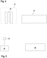
- FIG 4 shows a further embodiment of the automation system 1 according to the invention.
- the automation system 1 is used to control a packaging machine 19, which has a machine control (not shown) and an arrangement of sensors 11 and actuators which are connected to the machine control.
- the sensors 11 and actuators are connected to the computer network 9 via the Internet connection 10 (in Figure 4 also not shown).
- This also applies to a sensor 11 in the form of a light grid 20, which is designed as a measuring light grid 20.
- the light grid 20 calculates the number of objects in a storage space 21 that are to be processed into containers in the packaging machine 19.
- the computer network 9 informs the light grid 20 via the Internet connection 10 how many objects a container should contain. If the light grid 20 detects a sufficient number of objects, the packaging machine 19 is started via the light grid 20.
- the Packaging machine 19 receives information from the light grid 20 as to how many items are to be combined into one bundle.
- the light grid 20 If the light grid 20 detects errors in the storage space 21, it reports this to the computer network 9, which then triggers a service call.
- Figure 5 shows a further embodiment of the automation system 1 according to the invention.
- a distance sensor 22 is provided for detecting dimensions of objects 23.
- the objects 23 are fed to a packaging machine 24 for further processing, which in turn has an associated machine control of sensors 11 and/or actuators that are connected to a computer network 9 by means of the Internet connections 10.
- the dimensions determined with the distance sensor 22 are sent to the computer network 9. There, the determined dimensions are linked to empirical values, i.e. values from previous measurements, in order to obtain, for example, a measure of the reliability of the measured values of the distance sensor 22. These data are transmitted via the computer network 9 to the processing machine 24 so that the work processes of the processing machine 24 are selected depending on them.
Landscapes
- Engineering & Computer Science (AREA)
- General Engineering & Computer Science (AREA)
- Manufacturing & Machinery (AREA)
- Quality & Reliability (AREA)
- Physics & Mathematics (AREA)
- General Physics & Mathematics (AREA)
- Automation & Control Theory (AREA)
- Programmable Controllers (AREA)
- Selective Calling Equipment (AREA)
Description
- Die Erfindung betrifft eine Maschinensteuerung gemäß dem Anspruch 1.
- Derartige Automatisierungssysteme dienen generell zur Steuerung von Maschinen oder Anlagen. Maschinen oder Anlagen, auf welche sich die vorliegende Erfindung bezieht, können in unterschiedlichsten Ausprägungen ausgebildet sein, wobei hierzu insbesondere auch bewegliche Systeme, wie zum Beispiel Roboter oder fahrbare Maschinen gehören.
- Generell sind zur Steuerung der Maschine oder Anlage eine Maschinensteuerung in einer Steuerungsebene und eine Anzahl von Sensoren und/Aktoren in einer Sensor-Aktorebene vorgesehen. Die Sensoren beziehungsweise Aktoren übernehmen Überwachungsfunktionen oder prozesssteuernde Funktionen an der Maschine oder Anlage. Diese Sensoren und/oder Aktoren sind an Ein- und Ausgänge der Maschinensteuerung angeschlossen. Die Maschinensteuerung liest damit in den Sensoren und/oder Aktoren generierte Signale und generiert, insbesondere in Abhängigkeit dieser Signale Steuerbefehle, um den Betrieb der Maschine oder Anlage zu steuern.
- In bekannten Automatisierungssystemen ist zur Steuerung der Maschine oder Anlage ein Kommunikationsmodell einer Automatisierungspyramide vorgesehen, die neben der Sensor-Aktorebene und der dieser übergeordneten Steuerungsebene weitere Ebenen umfasst. Hierzu gehört im Allgemeinen eine der Steuerungsebene übergeordnete Prozessleitebene mit einem Prozessleitsystem. Darüber gibt es im Allgemeinen eine Betriebsleitebene mit Systemen zur Produktionsdatenerfassung und zur Produktionsfeinplanung sowie eine noch weiter übergeordnete Unternehmensebene mit Systemen zur Bestellabwicklung und Produktionsgrobplanung.
- Ein Vorteil derartiger Automatisierungssysteme besteht darin, dass mit der Maschinensteuerung auch schnell ablaufende Prozesse, insbesondere in Echtzeit ablaufende Steuer- und Regelvorgänge für die Maschine oder Anlage durchgeführt werden können.
- Ein Nachteil des hierarchisch aufgebauten Kommunikationsmodells einer Automatisierungspyramide besteht darin, dass an die Maschinensteuerung einerseits alle Sensoren und/oder Aktoren angeschlossen sind und andererseits auch die Kommunikation mit Systemen in den übergeordneten Ebenen über die Maschinensteuerung läuft, wodurch der Aufwand für die Maschinensteuerung insbesondere hinsichtlich ihrer Ein- und Ausgangsstruktur unerwünscht groß ist.
- In Leuze: "Leuze Electronic kooperiert mit Microsoft", 1. Februar 2017, XP055452447, gefunden im Internet:
URL:http://www.git-sicherheit.de/printpdf/23260 (D1)
sind Sensoren beschrieben, die in ein Automatisierungssystem eingebunden sind. Die Sensoren weisen Schnittstellen auf, die um ein OPC UA-Kommunikationsmodell erweitert sind. Damit ist es möglich einen Datenaustausch der Sensoren direkt mit einer Cloud bereitzustellen. Über die Schnittstellen erfolgt ein manipulationssicherer Datenaustausch, in dem zu übertragende Daten mit Authentifizierungen, Autorisierungen, Verschlüsselungen und Datenintegritäten mit Signaturen abgesichert sind. - Die
US 2016/024 62 94 A1 (D2) betrifft ein Automatisierungssystem mit Feldgeräten, die mit einer Rechnereinheit in ein Netzwerk eingebunden sind. Für das Automatisierungssystem wird ein Anlagenmodell vorgegeben, das mit der Rechnereinheit kontrolliert wird. Die Feldgeräte können als Sensoren ausgebildet sein. Die Rechnereinheit ist insbesondere ein Cloud-Rechner. Die Feldgerätekönnen direkt mit der Rechnereinheit Daten austauschen. - Die
US 2017/0075343 A1 betrifft ein System mit einem Feldgerät, das über eine Schnittstelle direkt mit einem Cloud-Rechner kommunizieren kann. Das Feldgerät kann als Sensor ausgebildet sein. - In Messtec Drives Automation: "Smart Sensor business: Keine Industrie 4.0 ohne intelligente Sensorik", 7. März 2017, XP055454942, Gefunden im Internet: URL:http://www.md-automation.de
ist die Integration von Sensoren in ein cloudbasiertes Steuerungsmodell beschrieben. - Die
US 2013/0211547 A1 betrifft ein Verfahren zum Integrieren von zumindest einem Feldgerät in ein Netzwerk der Automatisierungstechnik, bestehend aus mehreren in einer Automatisierungsanlage verteilt angeordneten Feldgeräten, die über zumindest einen Datenbus, auf dem ein Busprotokoll läuft, miteinander verbunden sind. Der Zugriff auf die Feldgeräte erfolgt über eine Feldzugriffseinheit, die mit zumindest einer Automatisierungs-/Integrations-Plattform und zumindest einem WebServer eines Service Providers kommuniziert. - Die
DE 10 2010 042 716 A1 betrifft ein System zum Betreiben einer Automatisierungsanlage mit mehreren in der Feldebene verteilt angeordneten Feldgeräten (F1, F2, F3), die über zumindest einen Datenbus (DB), auf dem ein Busprotokoll läuft, miteinander verbunden sind, wobei der Zugriff auf die Feldgeräte (F1, F2, F3) über eine Feldzugriffseinheit (PAP) erfolgt, die mit zumindest einer Automatisierungs-/Integrations-Plattform und zumindest einem WebServer (OPC-UA Server) eines Service Providers verbunden ist. Die geschäftsrelevante Logik (BI1, BI2, BI3, BI4) ist zumindest teilweise in zumindest einem der Feldgeräte (F1, F2, F3) und/oder in der Feldzugriffseinheit (PAP) gespeichert. - Die
EP 3 070 548 A2 betrifft einen cloudbasierten Controller, der physikalische Einheiten oder Prozesse eines Automatisierungssystems steuert. Der Controller kann Informationen analysieren und auf Basis der Analyseergebnisse Kontrollinstruktionen generieren. - Die
US 2014/0148969 A1 betrifft ein cloudbasiertes System mit mehreren räumlich verteilten Kühlvorrichtungen, die Temperatursensoren aufweisen. In einer Cloud werden Prozessdaten der Kühlvorrichtungen gespeichert. Zudem sind dort Module zur Durchführung von Temperaturkontrollen vorgesehen. - Die
EP 3 070 548 A2 betrifft ein Automatisierungssystem, dem ein cloud-basierter industrieller Controller zugeordnet ist. Der Controller kontrolliert Einheiten und Prozesse des Automatisierungssystems. Hierzu sammelt der Controller über ein Gateway Informationen des Automatisierungssystems. Abhängig hiervon generiert der Controller Kontrollanweisungen für das Automatisierungssystem. - Die
US 2014/148969 A1 betrifft ein cloud-basiertes System für Kühleinheiten. Jede Kühleinheit weist als Steuereinheit einen Microprozessor mit einer Firmware auf. Die Firmware wertet Sensordaten von Sensoren aus und kontrolliert Zustände von Aktoren. Diese Funktionen werden von einer Cloud kontrolliert. - Die
US 2004/0249651 A1 betrifft ein Prozesskontrollsystem zum Betrieb einer technischen Installation. Das Prozesskontrollsystem umfasst einen Prozesskontrollcomputer als zentrale Steuerung sowie mehrere dezentrale Feldgeräte, in denen eine Kontroll-Software implementiert ist. Damit können Einheiten der technischen Installation überwacht und gesteuert werden. - Der Erfindung liegt die Aufgabe zugrunde, ein Automatisierungssystem mit hoher Funktionalität bereitzustellen.
- Zur Lösung dieser Aufgabe sind die Merkmale des Anspruchs 1 vorgesehen. Vorteilhafte Ausführungsformen und zweckmäßige Weiterbildungen der Erfindung sind in den abhängigen Ansprüchen beschrieben.
- Das erfindungsgemäße Automatisierungssystem dient zur Steuerung einer Maschine oder Anlage und umfasst eine Maschinensteuerung in einer Steuerungsebene und eine Anzahl von der Maschine oder Anlage zugeordneten Sensoren und/oder Aktoren in einer Sensor-Aktorebene. Der Maschinensteuerung werden Sensorsignale der Sensoren und/oder Aktorsignale der Aktoren zugeführt. In der Maschinensteuerung werden Steuerbefehle für die Maschine oder Anlage generiert. Die Sensoren und/oder Aktoren tauschen über das Internet mittels manipulationssicheren Protokolle direkt Informationen mit einem wenigstens eine Rechnereinheit aufweisenden Rechnernetzwerk aus, wobei die Sensoren anhand einer eindeutigen Kennung von dem Rechnernetzwerk identifizierbar sind. In dem Rechnernetzwerk werden Steuerbefehle für die Maschine oder Anlage generiert, welche an wenigstens einen Sensor oder Aktor übertragen werden. In jedem Sensor oder Aktor sind Steuermittel zur Steuerung der Maschine oder Anlage in Abhängigkeit eines Steuerbefehls des Rechnernetzwerks ausgebildet. Speichermittel zur Speicherung der Kennung und Kommunikationsmittel zur Kommunikation mit dem Rechnernetzwerk sind vorhanden. Mit den Steuermitteln wird abhängig von einem Steuerbefehl des Rechnernetzwerks die Maschine oder Anlage direkt und ohne Umweg über die Maschinensteuerung gesteuert.
- Der Grundgedanke der Erfindung besteht somit darin, dass die der Maschine oder Anlage zugeordneten Sensoren und/oder Aktoren nicht allein von der übergeordneten Maschinensteuerung gesteuert sind. Vielmehr sind die Sensoren und/oder Aktoren über das Internet mit einem verteilten, das heißt nicht lokal an die Maschine angebundenen Rechnernetzwerk verbunden, das heißt die Sensoren und/oder Aktoren kommunizieren mit einer Cloud, wobei dadurch weitere Steuerbefehle, zusätzlich zu den Steuerbefehlen in der Maschinensteuerung, generiert werden.
- Wesentlich ist, dass die Kommunikation der Sensoren und/oder Aktoren mit der Cloud nicht über die Maschinensteuerung erfolgt, sondern direkt mit der Cloud. Die Maschinensteuerung kann damit einen einfacheren Aufbau aufweisen, da deren Funktionalität auf einige wesentliche Grundfunktionen beschränkt sein kann. Dies führt insbesondere zu einer konstruktiven Vereinfachung der Maschinensteuerung, insbesondere dahingehend, dass die Anzahl der kostenaufwändigen Ein- und Ausgänge bei der Maschinensteuerung begrenzt werden kann.
- Besonders vorteilhaft werden, abhängig von geforderten Reaktionszeiten für Steuerbefehle, diese von der Maschinensteuerung oder von dem Rechnernetzwerk generiert.
- Insbesondere werden Steuerbefehle mit kurzen Reaktionszeiten von der Maschinensteuerung und Steuerbefehle mit längeren Reaktionszeiten von dem Rechnernetzwerk durchgeführt.
- Da die Maschinensteuerung schnelle Steuer- und Regelvorgänge, insbesondere in Echtzeit, durchführen kann, werden derartige Prozesse mit dieser Maschinensteuerung durchgeführt. Zeitunkritischere Vorgänge, wie zum Beispiel das Starten oder Stoppen der Maschine oder Anlage werden über die Cloud durchgeführt, wodurch die Maschinensteuerung entlastet wird.
- Bei dem erfindungsgemäßen Automatisierungssystem werden somit sowohl die Funktionen einer lokalen Maschinensteuerung als auch einer Cloud, das heißt einem über das Internet verbundenen verteilten Rechnernetzwerk genutzt und zwar derart, dass sich deren Funktionalitäten optimal ergänzen. Die Aufteilung der von der Maschinensteuerung und dem Rechnernetzwerk durchzuführenden Aufgaben erfolgt zweckmäßig über das Rechnernetzwerk. Hierzu kann zum Beispiel ein autorisierter Benutzer entsprechende Eingaben im Rechnernetzwerk durchführen.
- Eine wesentliche Voraussetzung für die Funktion des erfindungsgemäßen Automatisierungssystems besteht darin, dass in jedem Sensor oder Aktor Steuermittel, Speichermittel und Kommunikationsmittel integriert sind, wobei mittels der Steuermittel die Maschine oder Anlage in Abhängigkeit eines Steuerbefehls des Rechnernetzwerks steuerbar ist, wobei in den Speichermitteln die Kennung gespeichert ist, und wobei mittels der Kommunikationsmittel die Kommunikation mit dem Rechnernetzwerk erfolgt.
- Damit sind die Sensoren beziehungsweise Aktoren zur Kommunikation mit der Cloud ausgebildet. Durch die Abspeicherung von eindeutigen Kennungen, insbesondere Adressen, sind diese Sensoren beziehungsweise Aktoren eindeutig in der Cloud identifizierbar.
- Durch die in den Sensoren beziehungsweise Aktoren vorgesehenen Kommunikationsmittel können diese mit dem Rechnernetzwerk bidirektional Informationen austauschen.
- Die Kommunikation erfolgt dabei zweckmäßig über standardisierte Software-Protokolle, wie zum Beispiel dem OPC-UA-Protokoll, wobei hierzu als Kommunikationsmittel in den Sensoren beziehungsweise Aktoren entsprechende Software-Module vorhanden sind.
- Wesentlich ist, dass diese Kommunikation manipulationssicher ist, was insbesondere durch eine Absicherung der übertragenen Informationen durch Prüfsummen erreicht wird.
- Die übertragenen Informationen enthalten vorzugsweise Daten und Metadaten. Bei den Daten kann es sich beispielsweise um Messwerte eines Sensors handeln, welche in Form von Zahlenwerten übertragen werden. Die diesen zugeordneten Metadaten definieren, um welche Art von Messwerten es sich handelt, beispielsweise um Distanzwerte mit einer bestimmten Einheit wie mm oder cm.
- Wesentlich ist weiter, dass jeder Sensor oder Aktor Steuermittel enthält. Mit diesen Steuermitteln kann abhängig von einem Steuerbefehl des Rechnernetzwerks die Maschine oder Anlage direkt und ohne Umweg über die Maschinensteuerung gesteuert werden. Im einfachsten Fall umfassen die Steuermittel einen Steuerausgang, über welchen ein Signal, im einfachsten Fall ein binäres Schaltsignal, an die Maschine oder Anlage ausgegeben wird.
- Die Sensoren und/oder Aktoren weisen somit eine erweiterte Funktionalität auf.
- Gemäß einer vorteilhaften Ausführungsform werden von wenigstens einem Sensor oder Aktor periodisch Signallaufzeiten für die Kommunikation mit dem Rechnernetzwerk ermittelt, und abhängig von der Signallaufzeit sind die applikationsspezifische Funktionalität des Sensors oder Aktors definierende Software-Module in dem Rechnernetzwerk gespeichert oder in den Sensor oder Aktor geladen.
- Dadurch wird die Funktionalität der Sensoren und/oder Aktoren weiter erweitert. Abhängig von der durchgeführten Ermittlung der Signallaufzeiten kann der jeweilige Sensor und/oder Aktor bestimmen ob Funktionen, insbesondere für die Maschine oder Anlage relevante Funktionen, von dem Rechnernetzwerk oder von dem jeweiligen Sensor oder Aktor selbst durchgeführt werden. Damit kann das Zusammenwirken der einzelnen Komponenten des Automatisierungssystems auf einfache Weise optimiert werden.
- Gemäß einer vorteilhaften Ausführungsform werden in einem Sensor oder Aktor generierte Zustandsinformationen mit oder ohne einen Selbsttest an das Rechnernetzwerk übertragen.
- Die Zustandsinformationen können Messwerte, die mit den Sensoren erfasst wurden, aktuelle Zustände der Aktoren sowie Parameter der Sensoren und Aktoren umfassen.
- Abhängig von diesen Zustandsinformationen können in der Cloud Steuerbefehle generiert werden, die zur Ausführung an wenigstens einen Sensor oder Aktor weitergegeben werden. Mit einem solchen Steuerbefehl kann zum Beispiel der Betrieb der Maschine oder Anlage gestartet oder gestoppt werden. Beispielsweise kann in der Cloud anhand der Zustandsinformationen geprüft werden, ob alle Sensoren und/oder Aktoren vorhanden sind und bestimmte Zustände einnehmen, so dass dann ein Steuerbefehl für den Start der Maschine generiert wird.
- Gemäß einer vorteilhaften Weiterbildung sind im Rechnernetzwerk maschinen- oder anlagenrelevante Daten gespeichert, welche an Sensoren und/oder Aktoren übertragbar sind.
- Bei diesen Daten kann es sich beispielsweise um Daten des Betreibers der Maschine oder Anlage handeln. Diese können gegebenenfalls als vertrauliche Daten so im Rechnernetzwerk hinterlegt sein, dass diese nur autorisierten Benutzern zugänglich sind. Je nach Applikation können diese Daten oder Teilmengen hiervon in einen Sensor und/oder Aktor geladen werden.
- Gemäß einer besonders vorteilhaften Ausgestaltung der Erfindung ist die Steuerungsebene und die Sensor-Aktorebene Bestandteil eines Kommunikationsmodells einer Automatisierungspyramide mit weiteren Ebenen, wobei das Rechnernetzwerk direkt mit Systemen in den weiteren Ebenen kommuniziert.
- Beispielsweise können abhängig von den Zustandsinformationen der Sensoren und/oder Aktoren Informationen über eine notwendige Wartung von Komponenten der Anlage oder von notwendigen Nachbestellungen von Geräten oder Maschinen gewonnen werden. Davon abhängig kann über die Cloud beispielsweise eine Bestellabwicklung oder ein Produktionsplanungssystem in einer übergeordneten Ebene wie einer Betriebsleitebene oder Unternehmens ebene angesprochen werden um dadurch die notwendigen Aktionen auszulösen.
- Gemäß einer weiteren vorteilhaften Ausführungsform der Erfindung kommuniziert das Rechnernetzwerk direkt mit Sensoren und/oder Aktoren oder Systemen in weiteren Ebenen eines Kommunikationsmodells einer Automatisierungspyramide von verschiedenen Maschinen oder Anlagen.
- Damit ist das Automatisierungssystem auf mehrere Anlagen oder Maschinen erweitert. Vorteilhaft hierbei ist, dass die Cloud anlagenübergreifend Informationen in den Sensoren und/oder Aktoren Informationen aufnehmen kann und diese gemeinsam auswerten kann um spezifisch für bestimmte Maschinen oder Anlagen Steuerbefehle zu generieren.
- Gemäß einer vorteilhaften Ausführungsform der Erfindung sind die Sensoren ganz oder teilweise optische Sensoren, insbesondere zur Objektdetektion, Objektidentifikation oder zur geometrischen Messung eines Objektabstands, einer Oberflächenkontur oder eines Objektvolumens.
- Die Erfindung wird im Folgenden anhand der Zeichnungen erläutert. Es zeigen:
- Figur 1:
- Schematische Prinzipdarstellung des erfindungsgemäßen Automatisierungssystems.
- Figur 2:
- Schematische Darstellung eines Sensors für das Automatisierungssystem gemäß
Figur 1 . - Figur 3:
- Erstes Ausführungsbeispiel des erfindungsgemäßen Automatisierungssystems.
- Figur 4:
- Zweites Ausführungsbeispiel des erfindungsgemäßen Automatisierungssystems.
-
Figur 1 zeigt den prinzipiellen Aufbau des erfindungsgemäßen Automatisierungssytems 1. Mit dem erfindungsgemäßen Automatisierungssystem 1 werden im vorliegenden Fall zwei Anlagen 2 gesteuert. Generell können mit dem Automatisierungssystem 1 auch Maschinen aller Art gesteuert werden. Weiterhin können mit dem Automatisierungssystem 1 auch nur eine oder mehr als zwei Maschinen oder Anlagen 2 gesteuert werden. - Jeder Anlage 2 sind in einem Kommunikationsmodell einer Automatisierungspyramide 3 hierarchisch gegliederte, in bestimmten Ebenen angeordnete Systeme zugeordnet. In einer Sensor-Aktorebene 4 sind Sensoren 11, die Prozesse der Anlage 2 überwachen, und Aktoren, die Prozesse in der Anlage 2 unterstützen oder kontrollieren, vorgesehen. In einer der Sensor-Aktorebene 4 übergeordneten Steuerungsebene 5 ist eine Maschinensteuerung vorgesehen, an welche die Sensoren 11 und/oder Aktoren über Ein- und Ausgänge angeschlossen sind. Die Maschinensteuerung ist zur Steuerung der Anlage 2 ausgebildet. In einer weiteren übergeordneten Prozessleitebene 6 ist ein Prozessleitsystem vorgesehen. In einer weiteren übergeordneten Betriebsleitebene 7 können Systeme zur Produktionsfeinplanung einer Produktionsdatenerfassung vorgesehen sein. In einer weiteren übergeordneten Unternehmensebene 8 können Systeme zur Produktionsgrobplanung und Bestellabwicklung vorgesehen sein.
- Erfindungsgemäß sind die Sensoren 11 und/Aktoren des Automatisierungssystems 1 über das Internet mit einem verteilten Rechnernetzwerk 9 verbunden, das mehrere dezentrale Rechnereinheiten aufweist. Im vorliegenden Fall ist nur eine Rechnereinheit vorgesehen. Die Internetverbindungen 10 können drahtlos oder drahtgebunden ausgeführt sein. Das über das Internet eingebundene Rechnernetzwerk 9 bildet eine Cloud.
- Wie
Figur 1 zeigt, sind die Sensoren 11 und/oder Aktoren direkt mit dem Rechnernetzwerk 9 über Internetverbindungen 10 verbunden, so dass diese direkt, das heißt ohne Umweg mit dem Rechnernetzwerk 9 kommunizieren können. Die Kommunikation über die Internetverbindung 10 erfolgt über standardisierte Software-Protokolle, wie zum Beispiel dem OPC-UA-Protokoll. Diese Datenübertragung ist manipulationssicher, insbesonder dadurch, dass die übertragenen Informationen durch Prüfnummern abgesichert sind. - Als Informationen werden Daten und Metadaten übertragen, wobei Metadaten zur Charakterisierung beziehungsweise Spezifizierung von bestimmten übertragenen Daten vorgesehen sind.
-
Figur 2 zeigt schematisch den Aufbau eines Sensors 11 für das Automatisierungssystem 1 gemäßFigur 1 . Der Sensor 11 weist in bekannter Weise ein Sensorelement 12 zur Objekterfassung und eine Auswerteeinheit 13 zur Auswertung von Sensorsignalen des Sensorelements 12 auf. Ist der Sensor 11 zur Distanzmessung ausgebildet, werden mit dem Sensorelement 12 Distanzwerte generiert, die als Daten in Form von Zahlenwerten an das Rechnernetzwerk 9 übertragen werden können. Diesen Daten sind Metadaten zugeordnet, die zum Beispiel definieren, dass es sich bei den Daten von Distanzwerte in mm oder cm handelt. - Der Sensor 11 umfasst weiterhin ein Kommunikationsmittel 14, ein Speichermittel 15 und ein Steuermittel 16. Mittels des Kommunikationsmittels 14 erfolgt die Kommunikation mit dem Rechnernetzwerk 9 über die Internetverbindung 10. Im Speichermittel 15 ist eine Kennung, insbesondere Adresse gespeichert, anhand derer der Sensor 11 eindeutig identifizierbar ist. Das Steuermittel 16 dient zur Ansteuerung der Anlage 2. Beispielsweise kann das Steuermittel 16 von einem Steuerausgang gebildet sein.
- Einen der
Figur 2 entsprechenden Aufbau weisen alle weiteren Sensoren 11 und/oder Aktoren des Automatisierungssystems 1 auf. - Die Sensoren 11 und/oder Aktoren übertragen Zustandsinformationen über die Internetverbindung 10 an das Rechnernetzwerk 9, wo diese gespeichert werden. Weiterhin können kundenspezifische Daten des Betreibers der Anlage 2 in der Rechnernetzwerk 9 gespeichert sein. Wenn diese Daten vertraulich sind, können diese beispielsweise nur von einem autorisierten Benutzer gespeichert werden.
- Erfindungsgemäß werden nicht nur in der Maschinensteuerung Steuerbefehle zur Steuerung der jeweiligen Anlage 2 generiert, sondern auch im Rechnernetzwerk 9, wobei dort zur Generierung der Steuerbefehle insbesondere die dort gespeicherten Zustandsinformationen und/oder kundenspezifischen Daten herangezogen werden können. Die Aufgabenverteilung zwischen Maschinensteuerung und Rechnernetzwerk 9 erfolgt vorteilhaft über das Rechnernetzwerk 9, wobei hierzu beispielsweise ein autorisierter Benutzer entsprechende Befehle in das Rechnernetzwerk 9 eingibt.
- Im vorliegenden Fall werden von jeder Maschinensteuerung schnell ablaufende Regel- und Steuervorgänge, die insbesondere in Echtzeit ablaufen, durchgeführt, wobei die Maschinensteuerung hierzu insbesondere in Abhängigkeit von Sensorsignalen der Sensoren 11 entsprechende Steuerbefehle generiert.
- Zeitunkritische Vorgänge werden dagegen von dem Rechnernetzwerk 9 gesteuert. Insbesondere wird der Start der jeweiligen Anlage 2 von den Zustandsinformationen der Sensoren 11 und/oder Aktoren für diese Anlage 2 generiert. Dabei wird im Rechnernetzwerk 9 geprüft, ob alle Sensoren 11 und/oder Aktoren vorhanden sind. Alternativ oder zusätzlich kann das Rechnernetzwerk 9 einen Steuerbefehl einer Anlage 2 in Abhängigkeit von Zustandsinformationen von Sensoren 11 und/oder Aktoren, die einer weiteren Anlage 2 zugeordnet sind, generieren. Entsprechend kann das Rechnernetzwerk 9 auch Steuerbefehle zum Stoppen einer Anlage 2 generieren.
- Mit den Steuerbefehlen des Rechnernetzwerks 9 kann auch eine Optimierung von Betriebsparametern von Sensoren 11 erfolgen. Im Rechnernetzwerk 9 können beispielsweise Informationen über Betriebsparameter mehrerer Sensoren 11 oder die Vorgeschichte des Betriebs von Sensoren 11 gespeichert sein. Abhängig hiervon kann das Rechnernetzwerk 9 Steuerbefehle zur Optimierung der Betriebsparameter an einen Sensor 11 senden. Beispiele hierfür sind die Belichtungszeiten von entfernungsmessenden Sensoren 11, die Verstärkung von Empfangssignalen vom Empfänger oder Sendeleistungen von Sendern von Sensoren 11, die optionalen Farbverteilungen von Kontrasttastern die Licht mit unterschiedlichen Farben emittieren oder auch Parameter von Sensoren 11 zur Codeerfassung wie Modulbreiten oder Abständen von zu erfassenden Codes.
- Weiterhin kann auf diese Weise beispielsweise die Raumbeleuchtung eines Kamerasensors optimiert werden. Die Kamera des Kamerasensors erfasst dabei Bildinformationen, die sie an das Rechnernetzwerk 9 sendet. Das Rechnernetzwerk 9 berechnet einen region of interest der für eine Applikation benötigt wird und sendet ein Softwaremodul für die Auswertung dieses region of interest an den Kamerasensor. Der Kamerasensor aktualisiert entsprechend seine Auswertesoftware, steuert dementsprechend eine RGB-Beleuchtung an, dass der Bildkontrast der Bilder bei einer Farbe optimal ist und kommuniziert die optimale Parametereinstellung an das Rechnernetzwerk 9, wo diese abgespeichert wird.
- Weiterhin ist es möglich, dass von wenigstens einem Sensor 11 oder Aktor periodisch Signallaufzeiten für die Kommunikation mit dem Rechnernetzwerk 9 ermittelt werden, und dass abhängig von der Signallaufzeit die applikationsspezifische Funktionalität des Sensors 11 oder Aktors definierende Softwaremodule in diesem Rechnernetzwerk 9 gespeichert oder in den Sensor 11 oder Aktor geladen sind.
- Dadurch kann die Aufgabenverteilung zwischen Sensoren 11 und/oder Aktoren einerseits und dem Rechnernetzwerk 9 andererseits geändert werden.
- Die Funktionalität des Automatisierungssystems 1 kann dadurch erweitert sein, dass abhängig von den im Rechnernetzwerk 9 gespeicherten Daten, insbesondere der Zustandsinformationen der Sensoren 11 und/oder Aktoren ermittelt wird, ob eine Wartung der Anlage notwendig ist oder ob einzelne Sensoren 11 und/oder Aktoren auszufallen drohen. Das Rechnernetzwerk 9 generiert dann Steuerbefehle, die direkt über Internetverbindungen 10 an Systeme des Automatisierungssystems 1, insbesondere Systeme der Unternehmens ebene 8 oder Betriebsleitebene 7, ausgegeben werden, um eine Wartung einzuleiten oder Bestellvorgänge von Sensoren 11 und/oder Aktoren auszulösen.
-
Figur 3 zeigt ein Ausführungsbeispiel des erfindungsgemäßen Automatisierungssystems 1 zur Steuerung einer Bearbeitungsmaschine 17, die zur Bearbeitung von Werkstücken dient. Die Bearbeitungsmaschine 17 weist mehrere Bearbeitungsstationen 17a bis 17d auf, die von den Werkstücken durchlaufen werden. Zur Prozesssteuerung sind mehrere binäre Sensoren 18a bis 18e wie zum Beispiel Lichtschranken vorgesehen, die an die nicht dargestellte Maschinensteuerung und an das ebenfalls nicht dargestellte Rechnernetzwerk 9 über die Internetverbindungen 10 angeschlossen sind. - Ein erster binärer Sensor 18a am Eingang der Bearbeitungsmaschine erkennt ein zu bearbeitendes Werkstück. Der binäre Sensor 18a sendet das entsprechende Sensorsignal an das Rechnernetzwerk 9, das aufgrund dessen die Betriebsbereitschaft der Bearbeitungsmaschine erkennt und einen Steuerbefehl an den binären Sensor 18a sendet, der über seine Speichermittel 15 die Bearbeitungsmaschine 17 startet. Der binäre Sensor 18a ermittelt dabei auch die Signallaufzeit für die Übersendung von Informationen über das Internet.
- Dadurch aktiviert der binäre Sensor 18a über das Rechnernetzwerk 9 einen binären Sensor 18e am Ausgang der Bearbeitungsmaschine, welcher das Ende des Bearbeitungsprozesses des Werkstücks erkennen kann. Sobald dieser binäre Sensor 18e das Ende des Bearbeitungsprozesses erkannt hat, meldet er dieses an das Rechnernetzwerk 9. Das Rechnernetzwerk 9 generiert dann einen Steuerbefehl, der an den ersten binären Sensor 18a gesendet wird, so dass dieser nach einer von dem Rechnernetzwerk 9 vorgegebenen, von der Signallaufzeit abhängigen Time-out-Zeit die Bearbeitungsmaschine 17 abschaltet.
-
Figur 4 zeigt ein weiteres Ausführungsbeispiel des erfindungsgemäßen Automatisierungssystems 1. In diesem Fall dient das Automatisierungssystem 1 zur Steuerung einer Verpackungsmaschine 19, die eine nicht dargestellte Maschinensteuerung und eine Anordnung von Sensoren 11 und Aktoren, welche an die Maschinensteuerung angeschlossen sind, aufweist. Zudem sind die Sensoren 11 und Aktoren über die Internetverbindung 10 an das Rechnernetzwerk 9 angeschlossen (inFigur 4 ebenfalls nicht dargestellt). Dies gilt auch für einen Sensor 11 in Form eines Lichtgitters 20, das als messendes Lichtgitter 20 ausgebildet ist. - Das Lichtgitter 20 berechnet die Anzahl der in einem Stauraum 21 vorhandenen Gegenstände, welche in der Verpackungsmaschine 19 zu Gebinden weiterverarbeitet werden sollen. Das Rechnernetzwerk 9 teilt über die Internetverbindung 10 dem Lichtgitter 20 mit, wie viele Gegenstände ein Gebinde umfassen soll. Detektiert das Lichtgitter 20 eine genügende Anzahl von Gegenständen, wird die Verpackungsmaschine 19 über das Lichtgitter 20 gestartet. Weiterhin erhält die Verpackungsmaschine 19 vom Lichtgitter 20 die Information, wie viele Gegenstände zu einem Gebinde zusammengefasst werden sollen.
- Detektiert das Lichtgitter 20 Fehler im Stauraum 21, meldet es dies dem Rechnernetzwerk 9, worauf dieses einen Serviceeinsatz auslöst.
-
Figur 5 zeigt ein weiteres Ausführungsbeispiel des erfindungsgemäßen Automatisierungssystems 1. In diesem Fall ist ein Distanzsensor 22 zur Erfassung von Abmessungen von Objekten 23 vorgesehen. Die Objekte 23 werden zur weiteren Verarbeitung einer Verpackungsmaschine 24 zugeführt, die wieder eine zugeordnete Maschinensteuerung von Sensoren 11 und/oder Aktoren aufweist, die mittels der Internetverbindungen 10 mit einem Rechnernetzwerk 9 verbunden sind. - In diesem Fall werden die mit dem Distanzsensor 22 ermittelten Abmessungen an das Rechnernetzwerk 9 gesendet. Dort werden die ermittelten Abmessungen mit Erfahrungswerten, das heißt Werten aus früheren Messungen, verknüpft, um beispielsweise ein Maß für die Zuverlässigkeit der Messwerte des Distanzsensors 22 zu erhalten. Diese Daten werden über das Rechnernetzwerk 9 an die Verarbeitungsmaschine 24 übermittelt, so dass abhängig hiervon die Arbeitsprozesse der Verarbeitungsmaschine 24 gewählt werden.
-
- (1)
- Automatisierungssystem
- (2)
- Anlagen
- (3)
- Automatisierungspyramide
- (4)
- Sensor-Aktorebene
- (5)
- Steuerungsebene
- (6)
- Prozessleitebene
- (7)
- Betriebsleitebene
- (8)
- Unternehmens ebene
- (9)
- Rechnernetzwerk
- (10)
- Internetverbindung
- (11)
- Sensor
- (12)
- Sensorelement
- (13)
- Auswerteeinheit
- (14)
- Kommunikationsmittel
- (15)
- Speichermittel
- (16)
- Steuermittel
- (17)
- Bearbeitungsmaschine
- (17a-17d)
- Bearbeitungsstationen
- (18a-18e)
- binäre Sensoren
- (19)
- Verpackungsmaschine
- (20)
- Lichtgitter
- (21)
- Stauraum
- (22)
- Distanzsensor
- (23)
- Objekt
- (24)
- Verarbeitungsmaschine
Claims (12)
- Automatisierungssystem (1) zur Steuerung einer Maschine oder Anlage (2), mit einer Maschinensteuerung in einer Steuerungsebene (5) und einer Anzahl von der Maschine oder Anlage (2) zugeordneten Sensoren (11) und/oder Aktoren in einer Sensor-Aktorebene (4), wobei Sensorsignale der Sensoren (11) und/oder Aktorsignale der Aktoren der Maschinensteuerung zugeführt werden und in der Maschinensteuerung Steuerbefehle für die Maschine oder Anlage (2) generiert werden, wobei die Sensoren (11) und/oder Aktoren über das Internet mittels manipulationssicherer Protokolle direkt Informationen mit einem wenigstens eine Rechnereinheit aufweisenden Rechnernetzwerk (9) austauschen, wobei die Sensoren (11) anhand einer eindeutigen Kennung von dem Rechnernetzwerk (9) identifizierbar sind, und wobei in dem Rechnernetzwerk (9) Steuerbefehle für die Maschine oder Anlage (2) generiert werden, welche an wenigstens einen Sensor (11) oder Aktor übertragen werden, dadurch gekennzeichnet, dass in jedem Sensor (11) oder Aktor Steuermittel (16), die zur Steuerung der Maschine oder Anlage (2) in Abhängigkeit eines Steuerbefehls des Rechnernetzwerks (9) ausgebildet sind und Speichermittel (15) zur Speicherung der Kennung und Kommunikationsmittel (14) zur Kommunikation mit dem Rechnernetzwerk (9) vorhanden sind, wobei mit den Steuermitteln (16) abhängig von einem Steuerbefehl des Rechnernetzwerks (9) die Maschine oder Anlage (2) direkt und ohne Umweg über die Maschinensteuerung gesteuert wird.
- Automatisierungssystem (1) nach Anspruch 1, dadurch gekennzeichnet, dass in einem Sensor (11) oder Aktor generierte Zustandsinformationen mit oder ohne einen Selbsttest an das Rechnernetzwerk (9) übertragen werden.
- Automatisierungssystem (1) nach Anspruch 1, dadurch gekennzeichnet, dass im Rechnernetzwerk (9) maschinen- oder anlagenrelevante Daten gespeichert sind, welche an Sensoren (11) und/oder Aktoren übertragbar sind.
- Automatisierungssystem (1) nach Anspruch 1, dadurch gekennzeichnet, dass die Steuerungsebene (5) und die Sensor-Aktorebene (4) Bestandteil eines Kommunikationsmodells einer Automatisierungspyramide (3) mit weiteren Ebenen ist, wobei das Rechnernetzwerk (9) direkt mit Systemen in den weiteren Ebenen kommuniziert.
- Automatisierungssystem (1) nach einem der Ansprüche 1 bis 4, dadurch gekennzeichnet, dass das Rechnernetzwerk (9) direkt mit Sensoren (11) und/ oder Aktoren oder Systemen in weiteren Ebenen eines Kommunikationsmodells einer Automatisierungspyramide (3) von verschiedenen Maschinen oder Anlagen (2) kommuniziert.
- Automatisierungssystem (1) nach einem der Ansprüche 1 bis 5, dadurch gekennzeichnet, dass abhängig von geforderten Reaktionszeiten für die Durchführung von Steuerbefehlen diese von der Maschinensteuerung oder von dem Rechnernetzwerk (9) generiert werden.
- Automatisierungssystem (1) nach Anspruch 6, dadurch gekennzeichnet, dass Steuerbefehle mit kurzen Reaktionszeiten von der Maschinensteuerung und Steuerbefehle mit längeren Reaktionszeiten von dem Rechnernetzwerk (9) durchgeführt werden.
- Automatisierungssystem (1) nach einem der Ansprüche 1 bis 7, dadurch gekennzeichnet, dass von wenigstens einem Sensor (11) oder Aktor periodisch Signallaufzeiten für die Kommunikation mit dem Rechnernetzwerk (9) ermittelt werden, und dass abhängig von der Signallaufzeit die applikationsspezifische Funktionalität des Sensors (11) oder Aktors definierende Softwaremodule in dem Rechnernetzwerk (9) gespeichert oder in den Sensor (11) oder Aktor geladen sind.
- Automatisierungssystem (1) nach einem der Ansprüche 1 bis 8, dadurch gekennzeichnet, dass die Kommunikation mit dem Rechnernetzwerk (9) über standardisierte Software-Protokolle, insbesondere über OPC-UA-Protokolle erfolgt.
- Automatisierungssystem (1) nach Anspruch 9, dadurch gekennzeichnet, dass zwischen dem Rechnernetzwerk (9) und weiteren Teilnehmern, insbesondere Sensoren (11) und/oder Aktoren Informationen ausgetauscht werden, welche Daten und die Daten charakterisierende Metadaten enthalten.
- Automatisierungssystem (1) nach Anspruch 10, dadurch gekennzeichnet, dass die übertragenen Informationen mit Prüfnummern abgesichert sind.
- Automatisierungssystem (1) nach einem der Ansprüche 1 bis 11, dadurch gekennzeichnet, dass die Sensoren ganz oder teilweise optische Sensoren, insbesondere zur Objektdetektion, Objektidentifikation oder zur geometrischen Messung eines Objektabstands, einer Oberflächenkontur oder eines Objektvolumens sind.
Priority Applications (1)
| Application Number | Priority Date | Filing Date | Title |
|---|---|---|---|
| EP17189689.7A EP3454152B1 (de) | 2017-09-06 | 2017-09-06 | Automatisierungssystem zur steuerung einer maschine oder anlage |
Applications Claiming Priority (1)
| Application Number | Priority Date | Filing Date | Title |
|---|---|---|---|
| EP17189689.7A EP3454152B1 (de) | 2017-09-06 | 2017-09-06 | Automatisierungssystem zur steuerung einer maschine oder anlage |
Publications (2)
| Publication Number | Publication Date |
|---|---|
| EP3454152A1 EP3454152A1 (de) | 2019-03-13 |
| EP3454152B1 true EP3454152B1 (de) | 2025-02-19 |
Family
ID=59829212
Family Applications (1)
| Application Number | Title | Priority Date | Filing Date |
|---|---|---|---|
| EP17189689.7A Active EP3454152B1 (de) | 2017-09-06 | 2017-09-06 | Automatisierungssystem zur steuerung einer maschine oder anlage |
Country Status (1)
| Country | Link |
|---|---|
| EP (1) | EP3454152B1 (de) |
Citations (3)
| Publication number | Priority date | Publication date | Assignee | Title |
|---|---|---|---|---|
| US20040249651A1 (en) * | 2001-08-07 | 2004-12-09 | Detlef Fischer | Method and process management system for the operation of a technical plant |
| US20140148969A1 (en) * | 2012-11-28 | 2014-05-29 | Visible Energy Inc. | Cloud-based refrigeration system |
| EP3070548A2 (de) * | 2015-03-16 | 2016-09-21 | Rockwell Automation Technologies, Inc. | Cloud-basierte industrielle steuerung |
Family Cites Families (4)
| Publication number | Priority date | Publication date | Assignee | Title |
|---|---|---|---|---|
| DE102010029952B4 (de) * | 2010-06-10 | 2019-06-27 | Endress + Hauser Process Solutions Ag | Verfahren zum Integrieren von zumindest einem Feldgerät in ein Netzwerk der Automatisierungstechnik |
| DE102010042716A1 (de) * | 2010-10-20 | 2012-04-26 | Endress + Hauser Process Solutions Ag | System und Verfahren zum Betreiben einer Automatisierungsanlage |
| DE102013111052A1 (de) * | 2013-10-07 | 2015-04-23 | Endress + Hauser Gmbh + Co. Kg | System zum flexiblen Betreiben einer Automatisierungsanlage |
| DE102014106632A1 (de) * | 2014-05-12 | 2015-11-12 | Krohne Messtechnik Gmbh | Feldgerät, Verfahren zum Betreiben eines Feldgerätes und Cloud-Dienst |
-
2017
- 2017-09-06 EP EP17189689.7A patent/EP3454152B1/de active Active
Patent Citations (3)
| Publication number | Priority date | Publication date | Assignee | Title |
|---|---|---|---|---|
| US20040249651A1 (en) * | 2001-08-07 | 2004-12-09 | Detlef Fischer | Method and process management system for the operation of a technical plant |
| US20140148969A1 (en) * | 2012-11-28 | 2014-05-29 | Visible Energy Inc. | Cloud-based refrigeration system |
| EP3070548A2 (de) * | 2015-03-16 | 2016-09-21 | Rockwell Automation Technologies, Inc. | Cloud-basierte industrielle steuerung |
Also Published As
| Publication number | Publication date |
|---|---|
| EP3454152A1 (de) | 2019-03-13 |
Similar Documents
| Publication | Publication Date | Title |
|---|---|---|
| DE102011006786B4 (de) | Produktsensor, Produkt mit Produktsensor, Anlage und Verfahren zur Kommunikation zwischen Produktsensor und Anlage | |
| EP0906596B1 (de) | Prozessautomatisierungssystem | |
| EP2082297B1 (de) | PROZESSAUTOMATISIERUNGSSYSTEM ZUR BESTIMMUNG, ZUR ÜBERWACHUNG UND/ODER ZUM BEEINFLUSSEN VON UNTERSCHIEDLICHEN PROZESSGRÖßEN UND/ODER ZUSTANDSGRÖßEN | |
| DE112015004984T5 (de) | Client-Vorrichtung zur Datenerfassung und Vorverarbeitung von prozessbezogenen Massendaten von mindestens einer CNC-Maschine oder einem Industrieroboter | |
| EP1425635B1 (de) | Überwachungssystem, sowie verfahren zur prozessbegleitenden überwachung von kollisions- bzw. überlastsituationen an werkzeugmaschinen | |
| DE102007039531A1 (de) | Verfahren zum Beschaffen von instandhaltungsrelevanten Informationen zu einer Anlage | |
| EP3699704B1 (de) | System und verfahren zum überprüfen von systemanforderungen von cyber-physikalischen systemen | |
| DE102018003942A1 (de) | Zum Kommunizieren mit einer Maschine verbundener Maschinensteuerungscomputer, Maschinensystem, Basis-Softwareanwendung, computerlesbares Speichermedium, Datenstruktur und Maschinensteuerungsverfahren | |
| DE102013005769A1 (de) | Maschine, Computerprogrammprodukt für ein Gerät zur Anzeige von Daten und Verfahren zur Statusüberwachung einer Maschine | |
| EP2042956A2 (de) | Schnittstelle zwischen einem Fertigungsmanagementsystem und einem Automatisierungssystem | |
| EP3881079A1 (de) | Laborsystem mit zumindest teilweise vernetzten laborgeräten und verfahren zur steuerung eines laborsystems mit zumindest teilweise vernetzten laborgeräten | |
| EP3538962A1 (de) | Verfahren zur analyse von fehlfunktionen in einer anlage der prozessautomatisierung | |
| DE102017125103A1 (de) | Einstellvorrichtung und einstellsystem zum konfigurieren von einstellungen für eine mehrzahl von maschinen | |
| EP2808749B1 (de) | Verfahren zum Austausch von Steuerungsinformationen zwischen Bedien- und Beobachtungsgeräten eines industriellen Automatisierungssystems und industrielles Automatisierungssystem | |
| EP3821306B1 (de) | Verfahren zum parametrieren eines sensorsystems | |
| DE102017101230A1 (de) | System mit mehreren Maschinen und mindestens einem Sensor | |
| EP3425324B2 (de) | Verfahren zur parametrierung eines sensors | |
| EP0537522A2 (de) | Vorrichtung und Verfahren zum Erfassen, ggf. Verarbeiten, Speichern und Übertragen von Daten jeglicher Art | |
| EP3361341A1 (de) | Verfahren zur überwachung der zustände von geräten eines automatisierungssystems sowie operator-system | |
| EP3454152A1 (de) | Automatisierungssystem zur steuerung einer maschine oder anlage | |
| DE102013005770A1 (de) | Maschine, Computerprogrammprodukt für ein Gerät zur Anzeige von Daten und Verfahren zur Energieüberwachung einer Maschine | |
| DE102017210453A1 (de) | Einrichtung und verfahren zum überwachen von daten eines automatisierungssystems für eine leit- und/oder steuerungsebene eines fertigungsmanagementsystems | |
| EP3454151B1 (de) | Automatisierungssystem zur steuerung einer maschine oder anlage | |
| WO2022167470A1 (de) | Verfahren zum prüfen von werkstücken und anordnung betreffend die prüfung von werkstücken | |
| DE102012018716A1 (de) | Vorrichtung und Verfahren zur Maschinenparametrierung mittels smart devices |
Legal Events
| Date | Code | Title | Description |
|---|---|---|---|
| PUAI | Public reference made under article 153(3) epc to a published international application that has entered the european phase |
Free format text: ORIGINAL CODE: 0009012 |
|
| STAA | Information on the status of an ep patent application or granted ep patent |
Free format text: STATUS: THE APPLICATION HAS BEEN PUBLISHED |
|
| AK | Designated contracting states |
Kind code of ref document: A1 Designated state(s): AL AT BE BG CH CY CZ DE DK EE ES FI FR GB GR HR HU IE IS IT LI LT LU LV MC MK MT NL NO PL PT RO RS SE SI SK SM TR |
|
| AX | Request for extension of the european patent |
Extension state: BA ME |
|
| STAA | Information on the status of an ep patent application or granted ep patent |
Free format text: STATUS: REQUEST FOR EXAMINATION WAS MADE |
|
| 17P | Request for examination filed |
Effective date: 20190509 |
|
| RBV | Designated contracting states (corrected) |
Designated state(s): AL AT BE BG CH CY CZ DE DK EE ES FI FR GB GR HR HU IE IS IT LI LT LU LV MC MK MT NL NO PL PT RO RS SE SI SK SM TR |
|
| STAA | Information on the status of an ep patent application or granted ep patent |
Free format text: STATUS: EXAMINATION IS IN PROGRESS |
|
| 17Q | First examination report despatched |
Effective date: 20210616 |
|
| P01 | Opt-out of the competence of the unified patent court (upc) registered |
Effective date: 20240502 |
|
| GRAP | Despatch of communication of intention to grant a patent |
Free format text: ORIGINAL CODE: EPIDOSNIGR1 |
|
| STAA | Information on the status of an ep patent application or granted ep patent |
Free format text: STATUS: GRANT OF PATENT IS INTENDED |
|
| INTG | Intention to grant announced |
Effective date: 20241210 |
|
| GRAS | Grant fee paid |
Free format text: ORIGINAL CODE: EPIDOSNIGR3 |
|
| GRAA | (expected) grant |
Free format text: ORIGINAL CODE: 0009210 |
|
| STAA | Information on the status of an ep patent application or granted ep patent |
Free format text: STATUS: THE PATENT HAS BEEN GRANTED |
|
| AK | Designated contracting states |
Kind code of ref document: B1 Designated state(s): AL AT BE BG CH CY CZ DE DK EE ES FI FR GB GR HR HU IE IS IT LI LT LU LV MC MK MT NL NO PL PT RO RS SE SI SK SM TR |
|
| REG | Reference to a national code |
Ref country code: GB Ref legal event code: FG4D Free format text: NOT ENGLISH |
|
| REG | Reference to a national code |
Ref country code: CH Ref legal event code: EP |
|
| REG | Reference to a national code |
Ref country code: IE Ref legal event code: FG4D Free format text: LANGUAGE OF EP DOCUMENT: GERMAN |
|
| REG | Reference to a national code |
Ref country code: DE Ref legal event code: R096 Ref document number: 502017016690 Country of ref document: DE |
|
| REG | Reference to a national code |
Ref country code: NL Ref legal event code: MP Effective date: 20250219 |
|
| PG25 | Lapsed in a contracting state [announced via postgrant information from national office to epo] |
Ref country code: RS Free format text: LAPSE BECAUSE OF FAILURE TO SUBMIT A TRANSLATION OF THE DESCRIPTION OR TO PAY THE FEE WITHIN THE PRESCRIBED TIME-LIMIT Effective date: 20250519 |
|
| PG25 | Lapsed in a contracting state [announced via postgrant information from national office to epo] |
Ref country code: FI Free format text: LAPSE BECAUSE OF FAILURE TO SUBMIT A TRANSLATION OF THE DESCRIPTION OR TO PAY THE FEE WITHIN THE PRESCRIBED TIME-LIMIT Effective date: 20250219 |
|
| PG25 | Lapsed in a contracting state [announced via postgrant information from national office to epo] |
Ref country code: PL Free format text: LAPSE BECAUSE OF FAILURE TO SUBMIT A TRANSLATION OF THE DESCRIPTION OR TO PAY THE FEE WITHIN THE PRESCRIBED TIME-LIMIT Effective date: 20250219 |
|
| PG25 | Lapsed in a contracting state [announced via postgrant information from national office to epo] |
Ref country code: ES Free format text: LAPSE BECAUSE OF FAILURE TO SUBMIT A TRANSLATION OF THE DESCRIPTION OR TO PAY THE FEE WITHIN THE PRESCRIBED TIME-LIMIT Effective date: 20250219 |
|
| REG | Reference to a national code |
Ref country code: LT Ref legal event code: MG9D |
|
| PG25 | Lapsed in a contracting state [announced via postgrant information from national office to epo] |
Ref country code: IS Free format text: LAPSE BECAUSE OF FAILURE TO SUBMIT A TRANSLATION OF THE DESCRIPTION OR TO PAY THE FEE WITHIN THE PRESCRIBED TIME-LIMIT Effective date: 20250619 Ref country code: NO Free format text: LAPSE BECAUSE OF FAILURE TO SUBMIT A TRANSLATION OF THE DESCRIPTION OR TO PAY THE FEE WITHIN THE PRESCRIBED TIME-LIMIT Effective date: 20250519 |
|
| PG25 | Lapsed in a contracting state [announced via postgrant information from national office to epo] |
Ref country code: NL Free format text: LAPSE BECAUSE OF FAILURE TO SUBMIT A TRANSLATION OF THE DESCRIPTION OR TO PAY THE FEE WITHIN THE PRESCRIBED TIME-LIMIT Effective date: 20250219 |
|
| PG25 | Lapsed in a contracting state [announced via postgrant information from national office to epo] |
Ref country code: HR Free format text: LAPSE BECAUSE OF FAILURE TO SUBMIT A TRANSLATION OF THE DESCRIPTION OR TO PAY THE FEE WITHIN THE PRESCRIBED TIME-LIMIT Effective date: 20250219 |
|
| PG25 | Lapsed in a contracting state [announced via postgrant information from national office to epo] |
Ref country code: PT Free format text: LAPSE BECAUSE OF FAILURE TO SUBMIT A TRANSLATION OF THE DESCRIPTION OR TO PAY THE FEE WITHIN THE PRESCRIBED TIME-LIMIT Effective date: 20250620 Ref country code: LV Free format text: LAPSE BECAUSE OF FAILURE TO SUBMIT A TRANSLATION OF THE DESCRIPTION OR TO PAY THE FEE WITHIN THE PRESCRIBED TIME-LIMIT Effective date: 20250219 |
|
| PG25 | Lapsed in a contracting state [announced via postgrant information from national office to epo] |
Ref country code: BG Free format text: LAPSE BECAUSE OF FAILURE TO SUBMIT A TRANSLATION OF THE DESCRIPTION OR TO PAY THE FEE WITHIN THE PRESCRIBED TIME-LIMIT Effective date: 20250219 Ref country code: GR Free format text: LAPSE BECAUSE OF FAILURE TO SUBMIT A TRANSLATION OF THE DESCRIPTION OR TO PAY THE FEE WITHIN THE PRESCRIBED TIME-LIMIT Effective date: 20250520 |
|
| PG25 | Lapsed in a contracting state [announced via postgrant information from national office to epo] |
Ref country code: SE Free format text: LAPSE BECAUSE OF FAILURE TO SUBMIT A TRANSLATION OF THE DESCRIPTION OR TO PAY THE FEE WITHIN THE PRESCRIBED TIME-LIMIT Effective date: 20250219 |
|
| PG25 | Lapsed in a contracting state [announced via postgrant information from national office to epo] |
Ref country code: SM Free format text: LAPSE BECAUSE OF FAILURE TO SUBMIT A TRANSLATION OF THE DESCRIPTION OR TO PAY THE FEE WITHIN THE PRESCRIBED TIME-LIMIT Effective date: 20250219 |
|
| PG25 | Lapsed in a contracting state [announced via postgrant information from national office to epo] |
Ref country code: DK Free format text: LAPSE BECAUSE OF FAILURE TO SUBMIT A TRANSLATION OF THE DESCRIPTION OR TO PAY THE FEE WITHIN THE PRESCRIBED TIME-LIMIT Effective date: 20250219 |
|
| PGFP | Annual fee paid to national office [announced via postgrant information from national office to epo] |
Ref country code: DE Payment date: 20250919 Year of fee payment: 9 |
|
| PG25 | Lapsed in a contracting state [announced via postgrant information from national office to epo] |
Ref country code: IT Free format text: LAPSE BECAUSE OF FAILURE TO SUBMIT A TRANSLATION OF THE DESCRIPTION OR TO PAY THE FEE WITHIN THE PRESCRIBED TIME-LIMIT Effective date: 20250219 |
|
| PG25 | Lapsed in a contracting state [announced via postgrant information from national office to epo] |
Ref country code: CZ Free format text: LAPSE BECAUSE OF FAILURE TO SUBMIT A TRANSLATION OF THE DESCRIPTION OR TO PAY THE FEE WITHIN THE PRESCRIBED TIME-LIMIT Effective date: 20250219 Ref country code: EE Free format text: LAPSE BECAUSE OF FAILURE TO SUBMIT A TRANSLATION OF THE DESCRIPTION OR TO PAY THE FEE WITHIN THE PRESCRIBED TIME-LIMIT Effective date: 20250219 |
|
| PG25 | Lapsed in a contracting state [announced via postgrant information from national office to epo] |
Ref country code: RO Free format text: LAPSE BECAUSE OF FAILURE TO SUBMIT A TRANSLATION OF THE DESCRIPTION OR TO PAY THE FEE WITHIN THE PRESCRIBED TIME-LIMIT Effective date: 20250219 |
|
| PG25 | Lapsed in a contracting state [announced via postgrant information from national office to epo] |
Ref country code: SK Free format text: LAPSE BECAUSE OF FAILURE TO SUBMIT A TRANSLATION OF THE DESCRIPTION OR TO PAY THE FEE WITHIN THE PRESCRIBED TIME-LIMIT Effective date: 20250219 |
|
| REG | Reference to a national code |
Ref country code: DE Ref legal event code: R097 Ref document number: 502017016690 Country of ref document: DE |
|
| PLBE | No opposition filed within time limit |
Free format text: ORIGINAL CODE: 0009261 |
|
| STAA | Information on the status of an ep patent application or granted ep patent |
Free format text: STATUS: NO OPPOSITION FILED WITHIN TIME LIMIT |
|
| REG | Reference to a national code |
Ref country code: CH Ref legal event code: L10 Free format text: ST27 STATUS EVENT CODE: U-0-0-L10-L00 (AS PROVIDED BY THE NATIONAL OFFICE) Effective date: 20251231 |
|
| 26N | No opposition filed |
Effective date: 20251120 |
|
| REG | Reference to a national code |
Ref country code: CH Ref legal event code: H13 Free format text: ST27 STATUS EVENT CODE: U-0-0-H10-H13 (AS PROVIDED BY THE NATIONAL OFFICE) Effective date: 20260504 |