EP3454112A2 - An electronic display with an improved dead-front presentation - Google Patents
An electronic display with an improved dead-front presentation Download PDFInfo
- Publication number
- EP3454112A2 EP3454112A2 EP18193859.8A EP18193859A EP3454112A2 EP 3454112 A2 EP3454112 A2 EP 3454112A2 EP 18193859 A EP18193859 A EP 18193859A EP 3454112 A2 EP3454112 A2 EP 3454112A2
- Authority
- EP
- European Patent Office
- Prior art keywords
- guest host
- dye layer
- display
- host dye
- backlit display
- Prior art date
- Legal status (The legal status is an assumption and is not a legal conclusion. Google has not performed a legal analysis and makes no representation as to the accuracy of the status listed.)
- Withdrawn
Links
- 230000005540 biological transmission Effects 0.000 claims abstract description 15
- 239000013078 crystal Substances 0.000 claims abstract description 8
- 230000007423 decrease Effects 0.000 claims description 2
- 230000003247 decreasing effect Effects 0.000 claims description 2
- 230000001419 dependent effect Effects 0.000 claims 1
- 239000000463 material Substances 0.000 description 5
- 239000004973 liquid crystal related substance Substances 0.000 description 3
- 210000004027 cell Anatomy 0.000 description 2
- 239000011521 glass Substances 0.000 description 2
- 239000004033 plastic Substances 0.000 description 2
- 239000000758 substrate Substances 0.000 description 2
- 239000004642 Polyimide Substances 0.000 description 1
- 238000010276 construction Methods 0.000 description 1
- 210000002858 crystal cell Anatomy 0.000 description 1
- 230000000694 effects Effects 0.000 description 1
- 238000005516 engineering process Methods 0.000 description 1
- AMGQUBHHOARCQH-UHFFFAOYSA-N indium;oxotin Chemical compound [In].[Sn]=O AMGQUBHHOARCQH-UHFFFAOYSA-N 0.000 description 1
- 239000000203 mixture Substances 0.000 description 1
- 230000004048 modification Effects 0.000 description 1
- 238000012986 modification Methods 0.000 description 1
- 230000003287 optical effect Effects 0.000 description 1
- 229920001721 polyimide Polymers 0.000 description 1
Images


Classifications
-
- B—PERFORMING OPERATIONS; TRANSPORTING
- B60—VEHICLES IN GENERAL
- B60K—ARRANGEMENT OR MOUNTING OF PROPULSION UNITS OR OF TRANSMISSIONS IN VEHICLES; ARRANGEMENT OR MOUNTING OF PLURAL DIVERSE PRIME-MOVERS IN VEHICLES; AUXILIARY DRIVES FOR VEHICLES; INSTRUMENTATION OR DASHBOARDS FOR VEHICLES; ARRANGEMENTS IN CONNECTION WITH COOLING, AIR INTAKE, GAS EXHAUST OR FUEL SUPPLY OF PROPULSION UNITS IN VEHICLES
- B60K35/00—Arrangement of adaptations of instruments
-
- G—PHYSICS
- G02—OPTICS
- G02F—OPTICAL DEVICES OR ARRANGEMENTS FOR THE CONTROL OF LIGHT BY MODIFICATION OF THE OPTICAL PROPERTIES OF THE MEDIA OF THE ELEMENTS INVOLVED THEREIN; NON-LINEAR OPTICS; FREQUENCY-CHANGING OF LIGHT; OPTICAL LOGIC ELEMENTS; OPTICAL ANALOGUE/DIGITAL CONVERTERS
- G02F1/00—Devices or arrangements for the control of the intensity, colour, phase, polarisation or direction of light arriving from an independent light source, e.g. switching, gating or modulating; Non-linear optics
- G02F1/01—Devices or arrangements for the control of the intensity, colour, phase, polarisation or direction of light arriving from an independent light source, e.g. switching, gating or modulating; Non-linear optics for the control of the intensity, phase, polarisation or colour
- G02F1/13—Devices or arrangements for the control of the intensity, colour, phase, polarisation or direction of light arriving from an independent light source, e.g. switching, gating or modulating; Non-linear optics for the control of the intensity, phase, polarisation or colour based on liquid crystals, e.g. single liquid crystal display cells
- G02F1/137—Devices or arrangements for the control of the intensity, colour, phase, polarisation or direction of light arriving from an independent light source, e.g. switching, gating or modulating; Non-linear optics for the control of the intensity, phase, polarisation or colour based on liquid crystals, e.g. single liquid crystal display cells characterised by the electro-optical or magneto-optical effect, e.g. field-induced phase transition, orientation effect, guest-host interaction or dynamic scattering
- G02F1/13725—Devices or arrangements for the control of the intensity, colour, phase, polarisation or direction of light arriving from an independent light source, e.g. switching, gating or modulating; Non-linear optics for the control of the intensity, phase, polarisation or colour based on liquid crystals, e.g. single liquid crystal display cells characterised by the electro-optical or magneto-optical effect, e.g. field-induced phase transition, orientation effect, guest-host interaction or dynamic scattering based on guest-host interaction
-
- B60K35/22—
-
- G—PHYSICS
- G02—OPTICS
- G02F—OPTICAL DEVICES OR ARRANGEMENTS FOR THE CONTROL OF LIGHT BY MODIFICATION OF THE OPTICAL PROPERTIES OF THE MEDIA OF THE ELEMENTS INVOLVED THEREIN; NON-LINEAR OPTICS; FREQUENCY-CHANGING OF LIGHT; OPTICAL LOGIC ELEMENTS; OPTICAL ANALOGUE/DIGITAL CONVERTERS
- G02F1/00—Devices or arrangements for the control of the intensity, colour, phase, polarisation or direction of light arriving from an independent light source, e.g. switching, gating or modulating; Non-linear optics
- G02F1/01—Devices or arrangements for the control of the intensity, colour, phase, polarisation or direction of light arriving from an independent light source, e.g. switching, gating or modulating; Non-linear optics for the control of the intensity, phase, polarisation or colour
- G02F1/13—Devices or arrangements for the control of the intensity, colour, phase, polarisation or direction of light arriving from an independent light source, e.g. switching, gating or modulating; Non-linear optics for the control of the intensity, phase, polarisation or colour based on liquid crystals, e.g. single liquid crystal display cells
- G02F1/133—Constructional arrangements; Operation of liquid crystal cells; Circuit arrangements
- G02F1/13306—Circuit arrangements or driving methods for the control of single liquid crystal cells
- G02F1/13318—Circuits comprising a photodetector
-
- G—PHYSICS
- G02—OPTICS
- G02F—OPTICAL DEVICES OR ARRANGEMENTS FOR THE CONTROL OF LIGHT BY MODIFICATION OF THE OPTICAL PROPERTIES OF THE MEDIA OF THE ELEMENTS INVOLVED THEREIN; NON-LINEAR OPTICS; FREQUENCY-CHANGING OF LIGHT; OPTICAL LOGIC ELEMENTS; OPTICAL ANALOGUE/DIGITAL CONVERTERS
- G02F1/00—Devices or arrangements for the control of the intensity, colour, phase, polarisation or direction of light arriving from an independent light source, e.g. switching, gating or modulating; Non-linear optics
- G02F1/01—Devices or arrangements for the control of the intensity, colour, phase, polarisation or direction of light arriving from an independent light source, e.g. switching, gating or modulating; Non-linear optics for the control of the intensity, phase, polarisation or colour
- G02F1/13—Devices or arrangements for the control of the intensity, colour, phase, polarisation or direction of light arriving from an independent light source, e.g. switching, gating or modulating; Non-linear optics for the control of the intensity, phase, polarisation or colour based on liquid crystals, e.g. single liquid crystal display cells
- G02F1/133—Constructional arrangements; Operation of liquid crystal cells; Circuit arrangements
- G02F1/1333—Constructional arrangements; Manufacturing methods
- G02F1/1335—Structural association of cells with optical devices, e.g. polarisers or reflectors
- G02F1/133526—Lenses, e.g. microlenses or Fresnel lenses
-
- G—PHYSICS
- G02—OPTICS
- G02F—OPTICAL DEVICES OR ARRANGEMENTS FOR THE CONTROL OF LIGHT BY MODIFICATION OF THE OPTICAL PROPERTIES OF THE MEDIA OF THE ELEMENTS INVOLVED THEREIN; NON-LINEAR OPTICS; FREQUENCY-CHANGING OF LIGHT; OPTICAL LOGIC ELEMENTS; OPTICAL ANALOGUE/DIGITAL CONVERTERS
- G02F1/00—Devices or arrangements for the control of the intensity, colour, phase, polarisation or direction of light arriving from an independent light source, e.g. switching, gating or modulating; Non-linear optics
- G02F1/01—Devices or arrangements for the control of the intensity, colour, phase, polarisation or direction of light arriving from an independent light source, e.g. switching, gating or modulating; Non-linear optics for the control of the intensity, phase, polarisation or colour
- G02F1/13—Devices or arrangements for the control of the intensity, colour, phase, polarisation or direction of light arriving from an independent light source, e.g. switching, gating or modulating; Non-linear optics for the control of the intensity, phase, polarisation or colour based on liquid crystals, e.g. single liquid crystal display cells
- G02F1/133—Constructional arrangements; Operation of liquid crystal cells; Circuit arrangements
- G02F1/1333—Constructional arrangements; Manufacturing methods
- G02F1/1337—Surface-induced orientation of the liquid crystal molecules, e.g. by alignment layers
- G02F1/13378—Surface-induced orientation of the liquid crystal molecules, e.g. by alignment layers by treatment of the surface, e.g. embossing, rubbing or light irradiation
- G02F1/133784—Surface-induced orientation of the liquid crystal molecules, e.g. by alignment layers by treatment of the surface, e.g. embossing, rubbing or light irradiation by rubbing
-
- G—PHYSICS
- G02—OPTICS
- G02F—OPTICAL DEVICES OR ARRANGEMENTS FOR THE CONTROL OF LIGHT BY MODIFICATION OF THE OPTICAL PROPERTIES OF THE MEDIA OF THE ELEMENTS INVOLVED THEREIN; NON-LINEAR OPTICS; FREQUENCY-CHANGING OF LIGHT; OPTICAL LOGIC ELEMENTS; OPTICAL ANALOGUE/DIGITAL CONVERTERS
- G02F1/00—Devices or arrangements for the control of the intensity, colour, phase, polarisation or direction of light arriving from an independent light source, e.g. switching, gating or modulating; Non-linear optics
- G02F1/01—Devices or arrangements for the control of the intensity, colour, phase, polarisation or direction of light arriving from an independent light source, e.g. switching, gating or modulating; Non-linear optics for the control of the intensity, phase, polarisation or colour
- G02F1/13—Devices or arrangements for the control of the intensity, colour, phase, polarisation or direction of light arriving from an independent light source, e.g. switching, gating or modulating; Non-linear optics for the control of the intensity, phase, polarisation or colour based on liquid crystals, e.g. single liquid crystal display cells
- G02F1/133—Constructional arrangements; Operation of liquid crystal cells; Circuit arrangements
- G02F1/1333—Constructional arrangements; Manufacturing methods
- G02F1/1347—Arrangement of liquid crystal layers or cells in which the final condition of one light beam is achieved by the addition of the effects of two or more layers or cells
- G02F1/13475—Arrangement of liquid crystal layers or cells in which the final condition of one light beam is achieved by the addition of the effects of two or more layers or cells in which at least one liquid crystal cell or layer is doped with a pleochroic dye, e.g. GH-LC cell
-
- G—PHYSICS
- G02—OPTICS
- G02F—OPTICAL DEVICES OR ARRANGEMENTS FOR THE CONTROL OF LIGHT BY MODIFICATION OF THE OPTICAL PROPERTIES OF THE MEDIA OF THE ELEMENTS INVOLVED THEREIN; NON-LINEAR OPTICS; FREQUENCY-CHANGING OF LIGHT; OPTICAL LOGIC ELEMENTS; OPTICAL ANALOGUE/DIGITAL CONVERTERS
- G02F1/00—Devices or arrangements for the control of the intensity, colour, phase, polarisation or direction of light arriving from an independent light source, e.g. switching, gating or modulating; Non-linear optics
- G02F1/01—Devices or arrangements for the control of the intensity, colour, phase, polarisation or direction of light arriving from an independent light source, e.g. switching, gating or modulating; Non-linear optics for the control of the intensity, phase, polarisation or colour
- G02F1/13—Devices or arrangements for the control of the intensity, colour, phase, polarisation or direction of light arriving from an independent light source, e.g. switching, gating or modulating; Non-linear optics for the control of the intensity, phase, polarisation or colour based on liquid crystals, e.g. single liquid crystal display cells
- G02F1/133—Constructional arrangements; Operation of liquid crystal cells; Circuit arrangements
- G02F1/1333—Constructional arrangements; Manufacturing methods
- G02F1/133305—Flexible substrates, e.g. plastics, organic film
-
- G—PHYSICS
- G02—OPTICS
- G02F—OPTICAL DEVICES OR ARRANGEMENTS FOR THE CONTROL OF LIGHT BY MODIFICATION OF THE OPTICAL PROPERTIES OF THE MEDIA OF THE ELEMENTS INVOLVED THEREIN; NON-LINEAR OPTICS; FREQUENCY-CHANGING OF LIGHT; OPTICAL LOGIC ELEMENTS; OPTICAL ANALOGUE/DIGITAL CONVERTERS
- G02F1/00—Devices or arrangements for the control of the intensity, colour, phase, polarisation or direction of light arriving from an independent light source, e.g. switching, gating or modulating; Non-linear optics
- G02F1/01—Devices or arrangements for the control of the intensity, colour, phase, polarisation or direction of light arriving from an independent light source, e.g. switching, gating or modulating; Non-linear optics for the control of the intensity, phase, polarisation or colour
- G02F1/13—Devices or arrangements for the control of the intensity, colour, phase, polarisation or direction of light arriving from an independent light source, e.g. switching, gating or modulating; Non-linear optics for the control of the intensity, phase, polarisation or colour based on liquid crystals, e.g. single liquid crystal display cells
- G02F1/133—Constructional arrangements; Operation of liquid crystal cells; Circuit arrangements
- G02F1/1333—Constructional arrangements; Manufacturing methods
- G02F1/133308—Support structures for LCD panels, e.g. frames or bezels
- G02F1/133331—Cover glasses
-
- G—PHYSICS
- G02—OPTICS
- G02F—OPTICAL DEVICES OR ARRANGEMENTS FOR THE CONTROL OF LIGHT BY MODIFICATION OF THE OPTICAL PROPERTIES OF THE MEDIA OF THE ELEMENTS INVOLVED THEREIN; NON-LINEAR OPTICS; FREQUENCY-CHANGING OF LIGHT; OPTICAL LOGIC ELEMENTS; OPTICAL ANALOGUE/DIGITAL CONVERTERS
- G02F1/00—Devices or arrangements for the control of the intensity, colour, phase, polarisation or direction of light arriving from an independent light source, e.g. switching, gating or modulating; Non-linear optics
- G02F1/01—Devices or arrangements for the control of the intensity, colour, phase, polarisation or direction of light arriving from an independent light source, e.g. switching, gating or modulating; Non-linear optics for the control of the intensity, phase, polarisation or colour
- G02F1/13—Devices or arrangements for the control of the intensity, colour, phase, polarisation or direction of light arriving from an independent light source, e.g. switching, gating or modulating; Non-linear optics for the control of the intensity, phase, polarisation or colour based on liquid crystals, e.g. single liquid crystal display cells
- G02F1/133—Constructional arrangements; Operation of liquid crystal cells; Circuit arrangements
- G02F1/1333—Constructional arrangements; Manufacturing methods
- G02F1/1335—Structural association of cells with optical devices, e.g. polarisers or reflectors
- G02F1/13356—Structural association of cells with optical devices, e.g. polarisers or reflectors characterised by the placement of the optical elements
-
- G—PHYSICS
- G02—OPTICS
- G02F—OPTICAL DEVICES OR ARRANGEMENTS FOR THE CONTROL OF LIGHT BY MODIFICATION OF THE OPTICAL PROPERTIES OF THE MEDIA OF THE ELEMENTS INVOLVED THEREIN; NON-LINEAR OPTICS; FREQUENCY-CHANGING OF LIGHT; OPTICAL LOGIC ELEMENTS; OPTICAL ANALOGUE/DIGITAL CONVERTERS
- G02F1/00—Devices or arrangements for the control of the intensity, colour, phase, polarisation or direction of light arriving from an independent light source, e.g. switching, gating or modulating; Non-linear optics
- G02F1/01—Devices or arrangements for the control of the intensity, colour, phase, polarisation or direction of light arriving from an independent light source, e.g. switching, gating or modulating; Non-linear optics for the control of the intensity, phase, polarisation or colour
- G02F1/13—Devices or arrangements for the control of the intensity, colour, phase, polarisation or direction of light arriving from an independent light source, e.g. switching, gating or modulating; Non-linear optics for the control of the intensity, phase, polarisation or colour based on liquid crystals, e.g. single liquid crystal display cells
- G02F1/133—Constructional arrangements; Operation of liquid crystal cells; Circuit arrangements
- G02F1/1333—Constructional arrangements; Manufacturing methods
- G02F1/1335—Structural association of cells with optical devices, e.g. polarisers or reflectors
- G02F1/1336—Illuminating devices
-
- G—PHYSICS
- G02—OPTICS
- G02F—OPTICAL DEVICES OR ARRANGEMENTS FOR THE CONTROL OF LIGHT BY MODIFICATION OF THE OPTICAL PROPERTIES OF THE MEDIA OF THE ELEMENTS INVOLVED THEREIN; NON-LINEAR OPTICS; FREQUENCY-CHANGING OF LIGHT; OPTICAL LOGIC ELEMENTS; OPTICAL ANALOGUE/DIGITAL CONVERTERS
- G02F1/00—Devices or arrangements for the control of the intensity, colour, phase, polarisation or direction of light arriving from an independent light source, e.g. switching, gating or modulating; Non-linear optics
- G02F1/01—Devices or arrangements for the control of the intensity, colour, phase, polarisation or direction of light arriving from an independent light source, e.g. switching, gating or modulating; Non-linear optics for the control of the intensity, phase, polarisation or colour
- G02F1/13—Devices or arrangements for the control of the intensity, colour, phase, polarisation or direction of light arriving from an independent light source, e.g. switching, gating or modulating; Non-linear optics for the control of the intensity, phase, polarisation or colour based on liquid crystals, e.g. single liquid crystal display cells
- G02F1/137—Devices or arrangements for the control of the intensity, colour, phase, polarisation or direction of light arriving from an independent light source, e.g. switching, gating or modulating; Non-linear optics for the control of the intensity, phase, polarisation or colour based on liquid crystals, e.g. single liquid crystal display cells characterised by the electro-optical or magneto-optical effect, e.g. field-induced phase transition, orientation effect, guest-host interaction or dynamic scattering
- G02F1/139—Devices or arrangements for the control of the intensity, colour, phase, polarisation or direction of light arriving from an independent light source, e.g. switching, gating or modulating; Non-linear optics for the control of the intensity, phase, polarisation or colour based on liquid crystals, e.g. single liquid crystal display cells characterised by the electro-optical or magneto-optical effect, e.g. field-induced phase transition, orientation effect, guest-host interaction or dynamic scattering based on orientation effects in which the liquid crystal remains transparent
- G02F1/1393—Devices or arrangements for the control of the intensity, colour, phase, polarisation or direction of light arriving from an independent light source, e.g. switching, gating or modulating; Non-linear optics for the control of the intensity, phase, polarisation or colour based on liquid crystals, e.g. single liquid crystal display cells characterised by the electro-optical or magneto-optical effect, e.g. field-induced phase transition, orientation effect, guest-host interaction or dynamic scattering based on orientation effects in which the liquid crystal remains transparent the birefringence of the liquid crystal being electrically controlled, e.g. ECB-, DAP-, HAN-, PI-LC cells
-
- G—PHYSICS
- G02—OPTICS
- G02F—OPTICAL DEVICES OR ARRANGEMENTS FOR THE CONTROL OF LIGHT BY MODIFICATION OF THE OPTICAL PROPERTIES OF THE MEDIA OF THE ELEMENTS INVOLVED THEREIN; NON-LINEAR OPTICS; FREQUENCY-CHANGING OF LIGHT; OPTICAL LOGIC ELEMENTS; OPTICAL ANALOGUE/DIGITAL CONVERTERS
- G02F2201/00—Constructional arrangements not provided for in groups G02F1/00 - G02F7/00
- G02F2201/58—Arrangements comprising a monitoring photodetector
-
- G—PHYSICS
- G02—OPTICS
- G02F—OPTICAL DEVICES OR ARRANGEMENTS FOR THE CONTROL OF LIGHT BY MODIFICATION OF THE OPTICAL PROPERTIES OF THE MEDIA OF THE ELEMENTS INVOLVED THEREIN; NON-LINEAR OPTICS; FREQUENCY-CHANGING OF LIGHT; OPTICAL LOGIC ELEMENTS; OPTICAL ANALOGUE/DIGITAL CONVERTERS
- G02F2202/00—Materials and properties
- G02F2202/04—Materials and properties dye
-
- G—PHYSICS
- G02—OPTICS
- G02F—OPTICAL DEVICES OR ARRANGEMENTS FOR THE CONTROL OF LIGHT BY MODIFICATION OF THE OPTICAL PROPERTIES OF THE MEDIA OF THE ELEMENTS INVOLVED THEREIN; NON-LINEAR OPTICS; FREQUENCY-CHANGING OF LIGHT; OPTICAL LOGIC ELEMENTS; OPTICAL ANALOGUE/DIGITAL CONVERTERS
- G02F2203/00—Function characteristic
- G02F2203/01—Function characteristic transmissive
-
- G—PHYSICS
- G02—OPTICS
- G02F—OPTICAL DEVICES OR ARRANGEMENTS FOR THE CONTROL OF LIGHT BY MODIFICATION OF THE OPTICAL PROPERTIES OF THE MEDIA OF THE ELEMENTS INVOLVED THEREIN; NON-LINEAR OPTICS; FREQUENCY-CHANGING OF LIGHT; OPTICAL LOGIC ELEMENTS; OPTICAL ANALOGUE/DIGITAL CONVERTERS
- G02F2203/00—Function characteristic
- G02F2203/64—Normally black display, i.e. the off state being black
-
- G—PHYSICS
- G09—EDUCATION; CRYPTOGRAPHY; DISPLAY; ADVERTISING; SEALS
- G09G—ARRANGEMENTS OR CIRCUITS FOR CONTROL OF INDICATING DEVICES USING STATIC MEANS TO PRESENT VARIABLE INFORMATION
- G09G2320/00—Control of display operating conditions
- G09G2320/04—Maintaining the quality of display appearance
-
- G—PHYSICS
- G09—EDUCATION; CRYPTOGRAPHY; DISPLAY; ADVERTISING; SEALS
- G09G—ARRANGEMENTS OR CIRCUITS FOR CONTROL OF INDICATING DEVICES USING STATIC MEANS TO PRESENT VARIABLE INFORMATION
- G09G2320/00—Control of display operating conditions
- G09G2320/06—Adjustment of display parameters
- G09G2320/0626—Adjustment of display parameters for control of overall brightness
- G09G2320/0646—Modulation of illumination source brightness and image signal correlated to each other
-
- G—PHYSICS
- G09—EDUCATION; CRYPTOGRAPHY; DISPLAY; ADVERTISING; SEALS
- G09G—ARRANGEMENTS OR CIRCUITS FOR CONTROL OF INDICATING DEVICES USING STATIC MEANS TO PRESENT VARIABLE INFORMATION
- G09G2360/00—Aspects of the architecture of display systems
- G09G2360/14—Detecting light within display terminals, e.g. using a single or a plurality of photosensors
- G09G2360/144—Detecting light within display terminals, e.g. using a single or a plurality of photosensors the light being ambient light
-
- G—PHYSICS
- G09—EDUCATION; CRYPTOGRAPHY; DISPLAY; ADVERTISING; SEALS
- G09G—ARRANGEMENTS OR CIRCUITS FOR CONTROL OF INDICATING DEVICES USING STATIC MEANS TO PRESENT VARIABLE INFORMATION
- G09G3/00—Control arrangements or circuits, of interest only in connection with visual indicators other than cathode-ray tubes
- G09G3/20—Control arrangements or circuits, of interest only in connection with visual indicators other than cathode-ray tubes for presentation of an assembly of a number of characters, e.g. a page, by composing the assembly by combination of individual elements arranged in a matrix no fixed position being assigned to or needed to be assigned to the individual characters or partial characters
- G09G3/34—Control arrangements or circuits, of interest only in connection with visual indicators other than cathode-ray tubes for presentation of an assembly of a number of characters, e.g. a page, by composing the assembly by combination of individual elements arranged in a matrix no fixed position being assigned to or needed to be assigned to the individual characters or partial characters by control of light from an independent source
- G09G3/3406—Control of illumination source
-
- G—PHYSICS
- G09—EDUCATION; CRYPTOGRAPHY; DISPLAY; ADVERTISING; SEALS
- G09G—ARRANGEMENTS OR CIRCUITS FOR CONTROL OF INDICATING DEVICES USING STATIC MEANS TO PRESENT VARIABLE INFORMATION
- G09G3/00—Control arrangements or circuits, of interest only in connection with visual indicators other than cathode-ray tubes
- G09G3/20—Control arrangements or circuits, of interest only in connection with visual indicators other than cathode-ray tubes for presentation of an assembly of a number of characters, e.g. a page, by composing the assembly by combination of individual elements arranged in a matrix no fixed position being assigned to or needed to be assigned to the individual characters or partial characters
- G09G3/34—Control arrangements or circuits, of interest only in connection with visual indicators other than cathode-ray tubes for presentation of an assembly of a number of characters, e.g. a page, by composing the assembly by combination of individual elements arranged in a matrix no fixed position being assigned to or needed to be assigned to the individual characters or partial characters by control of light from an independent source
- G09G3/36—Control arrangements or circuits, of interest only in connection with visual indicators other than cathode-ray tubes for presentation of an assembly of a number of characters, e.g. a page, by composing the assembly by combination of individual elements arranged in a matrix no fixed position being assigned to or needed to be assigned to the individual characters or partial characters by control of light from an independent source using liquid crystals
Definitions
- Electronic displays are provided in many contexts to electronically render digital information to a viewer.
- the electronic displays receive information, and render the information through lighted cells in patterns that reflect the texts and pictures employed to convey the information.
- the electronic displays may be implemented in a variety of environments where electronic displays have not traditionally been employed, such as a vehicle, home appliance, advertisement/billboard, and the like. Accordingly, for aesthetic purposes, when employing such electronic displays, ensuring that the electronic displays blend into a bezel or surrounding background may be desired.
- the following description relates to providing an electronic display with an improved dead-front presentation to a viewer of the electronic display.
- an electronic display comprising:
- the electronic display may comprise a transparent lens.
- transparent lens as used herein is conventionally used in technical field of displays to mean a substantially transparent layer or sheet, which may be clear or colored and either planar or curved, and which may be provided separately or in conjunction with other layers, and positioned between the viewer and display elements for providing information to the viewer.
- the dichroic guest host dye layer is preferably in physical abutment with the backlit display, and the transparent lens is preferably in physical abutment with the dichroic guest host dye layer.
- the dichroic guest host dye layer is preferably in physical abutment with the transparent lens, and the transparent lens is preferably in physical abutment with the backlit display.
- the electronic display comprises said air gap in between the backlit display and the dichroic guest host dye layer.
- an air gap may be desirable for any of several reasons.
- the designer may, for aesthetic reasons, wish for the display to appear to be recessed, for example deeper within an instrument panel.
- the designer may wish for the external surfaces of the display assembly nearest the viewer to be angled or curved with respect to the plane of the display screen itself.
- Another reason for providing an air gap is when there are other display elements in addition to the backlit display, for example a light or one or more gauges, in an area laterally adjacent to the display. Such a laterally adjacent area, and any associated display elements, will then also be hidden from view when the guest host dye layer is in the off state
- the electronic display may further comprise at least one mechanical gauge with the backlit display, for example laterally adjacent to the backlit display, said gauge being provided in said air gap.
- the dichroic guest host dye layer may be a curved layer.
- the transparent lens is curved where the transparent lens is in abutment with the dichroic guest host dye layer.
- the electronic display may further comprise a sensor for sensing a measure of the ambient light incident on the electronic display, the sensor being coupled to the circuit.
- the circuit may then be configured to maintain a transmission state of the dichroic guest host dye layer intermediate between the on and off states based on sensed data from the sensor. In this way, the circuit may be configured to increase the transmission of light through the guest host dye layer when the ambient light is increased and decrease the transmission of light through the guest host dye layer when the ambient light is decreased.
- X, Y, and Z will be construed to mean X only, Y only, Z only, or any combination of two or more items X, Y, and Z (e.g. XYZ, XZ, YZ, X).
- XYZ, XZ, YZ, X any combination of two or more items X, Y, and Z (e.g. XYZ, XZ, YZ, X).
- FIGs 1A and 1B illustrate an example of the operating principles associated with a dichroic guest host dye layer 100.
- an exemplary cell is shown, with an electrode 101 and 102.
- the term "dichroic guest host dye layer 100" includes the outer substrates, electrode layers and rubbing layers commonly used to construct and liquid crystal cell in addition to the guest host liquid crystal material.
- the substrates may be plastic, glass or other suitable materials.
- the transparent electrodes may be indium tin oxide (ITO) or other suitable materials.
- the rubbing layers used to anchor the liquid crystal material may be polyimide or other suitable materials.
- FIG. 1A an 'on' state is shown. As such, light is allowed to pass through.
- a collection of dichroic dye crystals 110 are shown, and are orthogonal to each of electrodes 101 and 102.
- an 'off state is shown. As such, light is effectively blocked, or the transmission of light is reduced. Thus, the same dichroic crystals are now in a non-orthogonal state 111. During the non-orthogonal state 111, light is not allowed to reflect through (or the transmission of light is limited). As such, a "dead-front" appearance is achieved. Intermediate levels of transmission are also possible between the fully “off” and fully “on” states.
- the amount of transmission allowed in each state may be set by the concentration of dichroic guest host dye employed in the construction of the layer 100.
- an implementer employing the layer in the manners described herein may adjust the concentration accordingly.
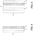
- Figure 2 illustrates a side-view of an implementation of a display 200 implementing the aspects disclosed herein.
- a backlit display 210 is shown first, at a left most position. This layer is physically furthest away from the viewer.
- a dichroic guest host dye layer 100 Disposed on the backlit layer 210 is a dichroic guest host dye layer 100.
- This layer is electrically coupled to a control signal (not shown), and in response to the display 210 displaying information, is effectively controlled to be in an 'on state' 110, and in response to the display 210 being off, is effectively controlled to be in an 'off state' 111.
- Intermediate transmission states are also possible and the dichroic guest host dye layer 100 may be adjusted or driven in accordance with the ambient lighting conditions using light sensor(s) in order to maintain display visibility while keeping the lowest useable transmission level to keep a dead-front appearance even when ambient light incident on the display changes.
- a glass or plastic lens 220 Disposed on the dichroic guest host dye layer 100 is a glass or plastic lens 220. This lens 220 is see-through, and allows light to be transmitted from the display 210, the dichroic guest host dye layer 100 (when in the 'on state' 110) to a viewer.
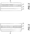
- FIG. 3 illustrates a side-view of an implementation of a display 300 implementing the aspects disclosed herein.
- Display 300 is similar to display 200, however the lens 220 and the dichroic guest host dye layer 100 are switched
- FIG. 4 illustrates a side-view of an implementation of a display 400 implementing the aspects disclosed herein.
- Display 400 is similar to display 200, except a lens 220 is not implemented.
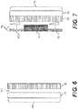
- FIG. 5 illustrates a side-view of an implementation of a display 500 implementing the aspects disclosed herein.
- Display 500 is similar to display 200; however, an air gap 510 is added in between the display 210 and the dichroic guest host dye layer 100.
- Figure 6 illustrates a side-view of an implementation of a display 600 implementing the aspects disclosed herein.
- Display 600 is similar to display 500; however, a lens 220 is not included.
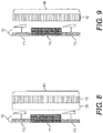
- FIGS 7 to 9 illustrate various side-views of a different sort of display 710 incorporating the aspects disclosed herein.
- the display 710 shown in these views incorporates at least one mechanical gauge and a backlit display.
- the display 710 includes two mechanical gauges 712, 713, with a backlit display 711 disposed between. Thus, all three display elements 711, 712, 713 are visible to a viewer of the display 710.
- the display 700 shown includes a dichroic guest host dye layer 100 disposed to overlap with the display 710 (but not in physical abutment), and a lens 220.
- the display 800 is similar to the display 700, however, the placement the dichroic guest host dye layer 100 and the lens 220 are switched.
- display 900 is similar to display 700, however the lens 220 is omitted.
- Figures 10 to 13 illustrate side-views of displays employing curved structures.
- the dichroic guest host dye layer 100 is replaced with a curved dichroic guest host dye layer 1010.
- the lens 220 is replaced with a curved lens 1020.
- display 1000 is shown with a curved dichroic guest host dye layer 1010 and a curved lens 1020.
- the curved lens 1020 may be omitted based on an implementer's choice.
- display 710 is implemented in lieu of display 100.
- display 1100 is similar to display 1000 except for the above-mentioned difference.
- display 1200 is similar to display 1100, however, the curved dichroic guest host dye layer 1010 and the curved lens 1020 are switched.
- display 1300 is similar to displays 1100 and 1200, except the curved lens 1020 is omitted
Abstract
Description
- Electronic displays are provided in many contexts to electronically render digital information to a viewer. The electronic displays receive information, and render the information through lighted cells in patterns that reflect the texts and pictures employed to convey the information.
- The electronic displays may be implemented in a variety of environments where electronic displays have not traditionally been employed, such as a vehicle, home appliance, advertisement/billboard, and the like. Accordingly, for aesthetic purposes, when employing such electronic displays, ensuring that the electronic displays blend into a bezel or surrounding background may be desired.
- This effect, also known as a "dead-panel" appearance or "dead-front" appearance, and has been attempted by numerous implementers of electronic displays integrated into a variety of contexts and environments. Several implementations have been attempted; however, with each implementation drawbacks become apparent.
- The following description relates to providing an electronic display with an improved dead-front presentation to a viewer of the electronic display.
- According to the invention, there is provided an electronic display, comprising:
- a backlit display configured to present content;
- a dichroic guest host dye layer disposed on the backlit display, or separated by an air gap from the backlit display, the guest host dye layer having: (i) an on state in which guest host dye crystals included therein are oriented in an orthogonal orientation to the backlit display whereby light from the backlit display is able to pass through the guest host dye layer; and (ii) an off state in which guest host dye crystals included therein are oriented in a parallel orientation to the backlit display whereby transmission of light through the guest host dye layer is effectively blocked; and
- a circuit electrically coupled to the backlit display and to the dichroic guest host dye layer and being configured, in response to the backlit display being on, to control the guest host dye layer to be in the on state and being configured, in response to the backlit display being off, to control the guest host dye layer to be in the off state.
- The electronic display may comprise a transparent lens. The term "transparent lens" as used herein is conventionally used in technical field of displays to mean a substantially transparent layer or sheet, which may be clear or colored and either planar or curved, and which may be provided separately or in conjunction with other layers, and positioned between the viewer and display elements for providing information to the viewer.
- The dichroic guest host dye layer is preferably in physical abutment with the backlit display, and the transparent lens is preferably in physical abutment with the dichroic guest host dye layer.
- The dichroic guest host dye layer is preferably in physical abutment with the transparent lens, and the transparent lens is preferably in physical abutment with the backlit display.
- In some embodiments, the electronic display comprises said air gap in between the backlit display and the dichroic guest host dye layer.
- The provision of an air gap may be desirable for any of several reasons. For example, the designer may, for aesthetic reasons, wish for the display to appear to be recessed, for example deeper within an instrument panel. Or, the designer may wish for the external surfaces of the display assembly nearest the viewer to be angled or curved with respect to the plane of the display screen itself.
- Another reason for providing an air gap is when there are other display elements in addition to the backlit display, for example a light or one or more gauges, in an area laterally adjacent to the display. Such a laterally adjacent area, and any associated display elements, will then also be hidden from view when the guest host dye layer is in the off state
- The electronic display may further comprise at least one mechanical gauge with the backlit display, for example laterally adjacent to the backlit display, said gauge being provided in said air gap.
- The dichroic guest host dye layer may be a curved layer.
- The transparent lens is curved where the transparent lens is in abutment with the dichroic guest host dye layer.
- The electronic display may further comprise a sensor for sensing a measure of the ambient light incident on the electronic display, the sensor being coupled to the circuit. The circuit may then be configured to maintain a transmission state of the dichroic guest host dye layer intermediate between the on and off states based on sensed data from the sensor. In this way, the circuit may be configured to increase the transmission of light through the guest host dye layer when the ambient light is increased and decrease the transmission of light through the guest host dye layer when the ambient light is decreased.
- Additional features of the invention will be set forth in the description which follows, and in part will be apparent from the description, or may be learned by practice of the invention.
- It is to be understood that both the foregoing general description and the following detailed description are exemplary and explanatory and are intended to provide further explanation of the invention as claimed. Other features and aspects will be apparent from the following detailed description, the drawings, and the claims.
- The invention will now be further described, by way of example only, and with reference to the accompanying drawings, in which like numerals refer to like items, and in which:
-
Figures 1A and 1B illustrate an example of the operating principles associated with a dichroic guest host dye layer; -
Figure 2 illustrates a side-view of an implementation of a display implementing the aspects disclosed herein; -
Figure 3 illustrates a side-view of a second implementation of a display implementing the aspects disclosed herein; -
Figure 4 illustrates a side-view of a third implementation of a display implementing the aspects disclosed herein; -
Figure 5 illustrates a side-view of a fourth implementation of a display implementing the aspects disclosed herein; -
Figure 6 illustrates a side-view of a fifth implementation of a display implementing the aspects disclosed herein; -
Figure 7 illustrates a side-view of a sixth implementation of a display implementing the aspects disclosed herein; -
Figure 8 illustrates a side-view of a seventh implementation of a display implementing the aspects disclosed herein; -
Figure 9 illustrates a side-view of an eighth implementation of a display implementing the aspects disclosed herein; -
Figure 10 illustrates a side-view of a ninth implementation of a display implementing the aspects disclosed herein; -
Figure 11 illustrates a side-view of a tenth implementation of a display implementing the aspects disclosed herein; -
Figure 12 illustrates a side-view of an eleventh implementation of a display implementing the aspects disclosed herein; and -
Figure 13 illustrates a side-view of a twelfth implementation of a display implementing the aspects disclosed herein. - The invention is described more fully hereinafter with references to the accompanying drawings, in which exemplary embodiments of the invention are shown. This invention may, however, be embodied in many different forms and should not be construed as limited to the embodiments set forth herein. Rather, these exemplary embodiments are provided so that this disclosure is thorough, and will fully convey the scope of the invention to those skilled in the art. It will be understood that for the purposes of this disclosure, "at least one of each" will be interpreted to mean any combination the enumerated elements following the respective language, including combination of multiples of the enumerated elements. For example, "at least one of X, Y, and Z" will be construed to mean X only, Y only, Z only, or any combination of two or more items X, Y, and Z (e.g. XYZ, XZ, YZ, X). Throughout the drawings and the detailed description, unless otherwise described, the same drawing reference numerals are understood to refer to the same elements, features, and structures. The relative size and depiction of these elements may be exaggerated for clarity, illustration, and convenience.
- The aspects disclosed herein employ dichroic guest host dye technology.
Figures 1A and 1B illustrate an example of the operating principles associated with a dichroic guesthost dye layer 100. Referring to bothFigures 1A and 1B , an exemplary cell is shown, with anelectrode host dye layer 100" includes the outer substrates, electrode layers and rubbing layers commonly used to construct and liquid crystal cell in addition to the guest host liquid crystal material. The substrates may be plastic, glass or other suitable materials. The transparent electrodes may be indium tin oxide (ITO) or other suitable materials. The rubbing layers used to anchor the liquid crystal material may be polyimide or other suitable materials. - Referring to
Figure 1A , an 'on' state is shown. As such, light is allowed to pass through. InFigure 1A , a collection ofdichroic dye crystals 110 are shown, and are orthogonal to each ofelectrodes - Referring to
Figure 1B , an 'off state is shown. As such, light is effectively blocked, or the transmission of light is reduced. Thus, the same dichroic crystals are now in anon-orthogonal state 111. During thenon-orthogonal state 111, light is not allowed to reflect through (or the transmission of light is limited). As such, a "dead-front" appearance is achieved. Intermediate levels of transmission are also possible between the fully "off" and fully "on" states. - In the employment of a dichroic guest
host dye layer 100, the amount of transmission allowed in each state may be set by the concentration of dichroic guest host dye employed in the construction of thelayer 100. As such, an implementer employing the layer in the manners described herein may adjust the concentration accordingly. -
Figure 2 illustrates a side-view of an implementation of adisplay 200 implementing the aspects disclosed herein. Abacklit display 210 is shown first, at a left most position. This layer is physically furthest away from the viewer. - Disposed on the
backlit layer 210 is a dichroic guesthost dye layer 100. This layer is electrically coupled to a control signal (not shown), and in response to thedisplay 210 displaying information, is effectively controlled to be in an 'on state' 110, and in response to thedisplay 210 being off, is effectively controlled to be in an 'off state' 111. Intermediate transmission states are also possible and the dichroic guesthost dye layer 100 may be adjusted or driven in accordance with the ambient lighting conditions using light sensor(s) in order to maintain display visibility while keeping the lowest useable transmission level to keep a dead-front appearance even when ambient light incident on the display changes. - Disposed on the dichroic guest
host dye layer 100 is a glass orplastic lens 220. Thislens 220 is see-through, and allows light to be transmitted from thedisplay 210, the dichroic guest host dye layer 100 (when in the 'on state' 110) to a viewer. - In
display 200, when the layers are shown in abutment with each other, this implies the layers are physically touching each other as shown, and physically in abutment with each other, utilizing optical bonding or other suitable means. -
Figure 3 illustrates a side-view of an implementation of adisplay 300 implementing the aspects disclosed herein.Display 300 is similar to display 200, however thelens 220 and the dichroic guesthost dye layer 100 are switched -
Figure 4 illustrates a side-view of an implementation of adisplay 400 implementing the aspects disclosed herein.Display 400 is similar to display 200, except alens 220 is not implemented. -
Figure 5 illustrates a side-view of an implementation of adisplay 500 implementing the aspects disclosed herein.Display 500 is similar to display 200; however, anair gap 510 is added in between thedisplay 210 and the dichroic guesthost dye layer 100. -
Figure 6 illustrates a side-view of an implementation of adisplay 600 implementing the aspects disclosed herein.Display 600 is similar to display 500; however, alens 220 is not included. -
Figures 7 to 9 illustrate various side-views of a different sort ofdisplay 710 incorporating the aspects disclosed herein. Thedisplay 710 shown in these views incorporates at least one mechanical gauge and a backlit display. - Referring to
Figure 7 , thedisplay 710 includes twomechanical gauges backlit display 711 disposed between. Thus, all threedisplay elements display 710. InFigure 7 , thedisplay 700 shown includes a dichroic guesthost dye layer 100 disposed to overlap with the display 710 (but not in physical abutment), and alens 220. - Referring to
Figure 8 , thedisplay 800 is similar to thedisplay 700, however, the placement the dichroic guesthost dye layer 100 and thelens 220 are switched. - Referring to
Figure 9 ,display 900 is similar to display 700, however thelens 220 is omitted. -
Figures 10 to 13 illustrate side-views of displays employing curved structures. In these implementations, the dichroic guesthost dye layer 100 is replaced with a curved dichroic guesthost dye layer 1010. Similarly, and where shown, thelens 220 is replaced with acurved lens 1020. - Referring to
Figure 10 ,display 1000 is shown with a curved dichroic guesthost dye layer 1010 and acurved lens 1020. Although not shown, in another embodiment thecurved lens 1020 may be omitted based on an implementer's choice. - Referring to
Figures 11 to 13 ,display 710 is implemented in lieu ofdisplay 100. InFigure 11 ,display 1100 is similar todisplay 1000 except for the above-mentioned difference. - In
Figure 12 ,display 1200 is similar todisplay 1100, however, the curved dichroic guesthost dye layer 1010 and thecurved lens 1020 are switched. Finally, inFigure 13 ,display 1300 is similar todisplays curved lens 1020 is omitted - As a person skilled in the art will readily appreciate, the above description is meant as an illustration of implementation of the principles this invention. This description is not intended to limit the scope or application of this invention in that the invention is susceptible to modification, variation and change, without departing from scope of this invention, as defined in the following claims.
Claims (8)
- An electronic display, comprising:a backlit display configured to present content;a dichroic guest host dye layer disposed on the backlit display, or separated by an air gap from the backlit display, the guest host dye layer having: (i) an on state in which guest host dye crystals included therein are oriented in an orthogonal orientation to the backlit display whereby light from the backlit display is able to pass through the guest host dye layer; and (ii) an off state in which guest host dye crystals included therein are oriented in a parallel orientation to the backlit display whereby transmission of light through the guest host dye layer is effectively blocked; anda circuit electrically coupled to the backlit display and to the dichroic guest host dye layer and being configured, in response to the backlit display being on, to control the guest host dye layer to be in the on state and being configured, in response to the backlit display being off, to control the guest host dye layer to be in the off state.
- The electronic display according to claim 1, further comprising a transparent lens.
- The electronic display according to claim 1 or claim 2, wherein the dichroic guest host dye layer is in physical abutment with the backlit display, and the transparent lens is in physical abutment with the dichroic guest host dye layer.
- The electronic display according to claim 2, wherein the dichroic guest host dye layer is in physical abutment with the transparent lens, and the transparent lens is in physical abutment with the backlit display.
- The electronic display according to claim 1 or claim 2, in which said dichroic guest host dye layer is separated by an air gap from the backlit display, wherein the electronic display further comprises at least one mechanical gauge included with the backlit display said gauge being provided in said air gap.
- The display according to claim 5, wherein the dichroic guest host dye layer is a curved layer.
- The electronic display according to claim 6 when dependent from claim 2, wherein the transparent lens is curved where the transparent lens is in abutment with the dichroic guest host dye layer.
- The electronic display according to any preceding claim, further comprising a sensor for sensing a measure of the ambient light incident on the electronic display, the sensor being coupled to said circuit, wherein the circuit is configured to maintain a transmission state of the dichroic guest host dye layer intermediate between said on state and said off state based on sensed data from the sensor whereby said circuit increases the transmission of light through the guest host dye layer when the ambient light is increased and decreases the transmission of light through the guest host dye layer when the ambient light is decreased.
Applications Claiming Priority (1)
| Application Number | Priority Date | Filing Date | Title |
|---|---|---|---|
| US15/700,994 US20190079333A1 (en) | 2017-09-11 | 2017-09-11 | Electronic display with an improved dead-front presentation |
Publications (2)
| Publication Number | Publication Date |
|---|---|
| EP3454112A2 true EP3454112A2 (en) | 2019-03-13 |
| EP3454112A3 EP3454112A3 (en) | 2019-04-24 |
Family
ID=63642522
Family Applications (1)
| Application Number | Title | Priority Date | Filing Date |
|---|---|---|---|
| EP18193859.8A Withdrawn EP3454112A3 (en) | 2017-09-11 | 2018-09-11 | An electronic display with an improved dead-front presentation |
Country Status (3)
| Country | Link |
|---|---|
| US (1) | US20190079333A1 (en) |
| EP (1) | EP3454112A3 (en) |
| CN (1) | CN109491167A (en) |
Families Citing this family (1)
| Publication number | Priority date | Publication date | Assignee | Title |
|---|---|---|---|---|
| WO2024000042A1 (en) * | 2022-06-30 | 2024-01-04 | Breville Pty Limited | Kitchen appliance |
Family Cites Families (15)
| Publication number | Priority date | Publication date | Assignee | Title |
|---|---|---|---|---|
| JPS58125084A (en) * | 1982-01-21 | 1983-07-25 | 株式会社東芝 | Liquid crystal display and manufacture thereof |
| US4527864A (en) * | 1983-03-29 | 1985-07-09 | Xerox Corporation | High contrast liquid crystal display devices |
| US4506956A (en) * | 1983-03-29 | 1985-03-26 | Xerox Corporation | Multicolor liquid crystal display with a dead front |
| US5343313A (en) * | 1990-03-20 | 1994-08-30 | James L. Fergason | Eye protection system with heads up display |
| JPH04199024A (en) * | 1990-11-29 | 1992-07-20 | Hitachi Ltd | Liquid crystal display element and display device using the same |
| US5220442A (en) * | 1991-09-06 | 1993-06-15 | Xerox Corporation | Method of making color liquid crystal display with dead front appearance |
| JPH11279558A (en) * | 1998-01-27 | 1999-10-12 | Hitachi Maxell Ltd | Liquid crystal composition of polymer dispersion type and liquid crystal display device containing the same |
| US6166787A (en) * | 1998-03-17 | 2000-12-26 | Motorola, Inc. | Optical display device having prismatic film for enhanced viewing |
| US6975369B1 (en) * | 2002-12-12 | 2005-12-13 | Gelcore, Llc | Liquid crystal display with color backlighting employing light emitting diodes |
| US8040233B2 (en) * | 2008-06-16 | 2011-10-18 | Qualcomm Incorporated | Methods and systems for configuring mobile devices using sensors |
| US20100315348A1 (en) * | 2009-06-11 | 2010-12-16 | Motorola, Inc. | Data entry-enhancing touch screen surface |
| US8860819B2 (en) * | 2013-01-08 | 2014-10-14 | Peripheral Vision, Inc. | Automated lighting system characterization device and system |
| US9785029B2 (en) * | 2015-01-17 | 2017-10-10 | Alpine Electronics, Inc. | Display device |
| US10675975B2 (en) * | 2015-04-17 | 2020-06-09 | Visteon Global Technologies, Inc. | Glass lens assembly with an elastic adhesive |
| US9875722B2 (en) * | 2015-08-05 | 2018-01-23 | International Business Machines Corporation | Optimized screen brightness control using multi-point light intensity input |
-
2017
- 2017-09-11 US US15/700,994 patent/US20190079333A1/en not_active Abandoned
-
2018
- 2018-09-10 CN CN201811051430.0A patent/CN109491167A/en active Pending
- 2018-09-11 EP EP18193859.8A patent/EP3454112A3/en not_active Withdrawn
Non-Patent Citations (1)
| Title |
|---|
| None |
Also Published As
| Publication number | Publication date |
|---|---|
| US20190079333A1 (en) | 2019-03-14 |
| EP3454112A3 (en) | 2019-04-24 |
| CN109491167A (en) | 2019-03-19 |
Similar Documents
| Publication | Publication Date | Title |
|---|---|---|
| US20170103718A1 (en) | Compositing display | |
| CN110082940B (en) | Display device and electronic apparatus | |
| US6654070B1 (en) | Interactive heads up display (IHUD) | |
| US11714328B2 (en) | Terminal having color-changing layer | |
| US20180012526A1 (en) | Mirror having an integrated electronic display | |
| US20110175902A1 (en) | Multilayer display device | |
| US20100045620A1 (en) | Integration design for capacitive touch panels and liquid crystal displays | |
| KR20090021081A (en) | Light switch having plural shutters | |
| CN103377611A (en) | Display unit | |
| CN101916009B (en) | Smectic-state liquid crystal display | |
| US20090172986A1 (en) | Media display device and method of operation thereof | |
| EP1804113A1 (en) | Backlit electronic display | |
| CN109491134A (en) | A kind of display device | |
| AU2011221666B2 (en) | Touch screen module structure | |
| CN103969899A (en) | Semi-transmission and semi-reflection liquid crystal display panel and liquid crystal display | |
| EP3454112A2 (en) | An electronic display with an improved dead-front presentation | |
| CN113516908A (en) | Vehicle-mounted double-screen display structure | |
| CN209118011U (en) | Peep-proof display screen | |
| US20070085815A1 (en) | Automatic liquid crystal display contrast adjustment | |
| CN102496351B (en) | Control method for display device and display device adopting same | |
| SG191344A1 (en) | Display device | |
| EP3454114B1 (en) | Electronic display with mulitiple polarizer layers | |
| US20160178832A1 (en) | Backlight module, transparent display panel and transparent display apparatus | |
| CN108694911B (en) | Temperature sensing module and temperature sensing method of display device and display device | |
| CN110969949A (en) | Composite display screen, composite display screen module and display control method thereof |
Legal Events
| Date | Code | Title | Description |
|---|---|---|---|
| PUAI | Public reference made under article 153(3) epc to a published international application that has entered the european phase |
Free format text: ORIGINAL CODE: 0009012 |
|
| AK | Designated contracting states |
Kind code of ref document: A2 Designated state(s): AL AT BE BG CH CY CZ DE DK EE ES FI FR GB GR HR HU IE IS IT LI LT LU LV MC MK MT NL NO PL PT RO RS SE SI SK SM TR |
|
| AX | Request for extension of the european patent |
Extension state: BA ME |
|
| PUAL | Search report despatched |
Free format text: ORIGINAL CODE: 0009013 |
|
| AK | Designated contracting states |
Kind code of ref document: A3 Designated state(s): AL AT BE BG CH CY CZ DE DK EE ES FI FR GB GR HR HU IE IS IT LI LT LU LV MC MK MT NL NO PL PT RO RS SE SI SK SM TR |
|
| AX | Request for extension of the european patent |
Extension state: BA ME |
|
| RIC1 | Information provided on ipc code assigned before grant |
Ipc: G02F 1/133 20060101AFI20190319BHEP Ipc: G02F 1/1333 20060101ALI20190319BHEP Ipc: G02F 1/1335 20060101ALN20190319BHEP Ipc: G02F 1/1347 20060101ALI20190319BHEP |
|
| STAA | Information on the status of an ep patent application or granted ep patent |
Free format text: STATUS: THE APPLICATION IS DEEMED TO BE WITHDRAWN |
|
| 18D | Application deemed to be withdrawn |
Effective date: 20191025 |