EP3454056A1 - Biosensor - Google Patents
Biosensor Download PDFInfo
- Publication number
- EP3454056A1 EP3454056A1 EP16891576.7A EP16891576A EP3454056A1 EP 3454056 A1 EP3454056 A1 EP 3454056A1 EP 16891576 A EP16891576 A EP 16891576A EP 3454056 A1 EP3454056 A1 EP 3454056A1
- Authority
- EP
- European Patent Office
- Prior art keywords
- opening
- substrate
- introduction
- sample
- spacer substrate
- Prior art date
- Legal status (The legal status is an assumption and is not a legal conclusion. Google has not performed a legal analysis and makes no representation as to the accuracy of the status listed.)
- Withdrawn
Links
Images


Classifications
-
- G—PHYSICS
- G01—MEASURING; TESTING
- G01N—INVESTIGATING OR ANALYSING MATERIALS BY DETERMINING THEIR CHEMICAL OR PHYSICAL PROPERTIES
- G01N27/00—Investigating or analysing materials by the use of electric, electrochemical, or magnetic means
- G01N27/26—Investigating or analysing materials by the use of electric, electrochemical, or magnetic means by investigating electrochemical variables; by using electrolysis or electrophoresis
- G01N27/28—Electrolytic cell components
- G01N27/30—Electrodes, e.g. test electrodes; Half-cells
- G01N27/327—Biochemical electrodes, e.g. electrical or mechanical details for in vitro measurements
- G01N27/3271—Amperometric enzyme electrodes for analytes in body fluids, e.g. glucose in blood
- G01N27/3272—Test elements therefor, i.e. disposable laminated substrates with electrodes, reagent and channels
-
- C—CHEMISTRY; METALLURGY
- C12—BIOCHEMISTRY; BEER; SPIRITS; WINE; VINEGAR; MICROBIOLOGY; ENZYMOLOGY; MUTATION OR GENETIC ENGINEERING
- C12Q—MEASURING OR TESTING PROCESSES INVOLVING ENZYMES, NUCLEIC ACIDS OR MICROORGANISMS; COMPOSITIONS OR TEST PAPERS THEREFOR; PROCESSES OF PREPARING SUCH COMPOSITIONS; CONDITION-RESPONSIVE CONTROL IN MICROBIOLOGICAL OR ENZYMOLOGICAL PROCESSES
- C12Q1/00—Measuring or testing processes involving enzymes, nucleic acids or microorganisms; Compositions therefor; Processes of preparing such compositions
- C12Q1/001—Enzyme electrodes
-
- G—PHYSICS
- G01—MEASURING; TESTING
- G01N—INVESTIGATING OR ANALYSING MATERIALS BY DETERMINING THEIR CHEMICAL OR PHYSICAL PROPERTIES
- G01N27/00—Investigating or analysing materials by the use of electric, electrochemical, or magnetic means
- G01N27/26—Investigating or analysing materials by the use of electric, electrochemical, or magnetic means by investigating electrochemical variables; by using electrolysis or electrophoresis
- G01N27/416—Systems
- G01N27/49—Systems involving the determination of the current at a single specific value, or small range of values, of applied voltage for producing selective measurement of one or more particular ionic species
-
- G—PHYSICS
- G01—MEASURING; TESTING
- G01N—INVESTIGATING OR ANALYSING MATERIALS BY DETERMINING THEIR CHEMICAL OR PHYSICAL PROPERTIES
- G01N33/00—Investigating or analysing materials by specific methods not covered by groups G01N1/00 - G01N31/00
- G01N33/48—Biological material, e.g. blood, urine; Haemocytometers
- G01N33/50—Chemical analysis of biological material, e.g. blood, urine; Testing involving biospecific ligand binding methods; Immunological testing
- G01N33/72—Chemical analysis of biological material, e.g. blood, urine; Testing involving biospecific ligand binding methods; Immunological testing involving blood pigments, e.g. haemoglobin, bilirubin or other porphyrins; involving occult blood
- G01N33/721—Haemoglobin
- G01N33/725—Haemoglobin using peroxidative activity
-
- G—PHYSICS
- G01—MEASURING; TESTING
- G01N—INVESTIGATING OR ANALYSING MATERIALS BY DETERMINING THEIR CHEMICAL OR PHYSICAL PROPERTIES
- G01N33/00—Investigating or analysing materials by specific methods not covered by groups G01N1/00 - G01N31/00
- G01N33/48—Biological material, e.g. blood, urine; Haemocytometers
- G01N33/50—Chemical analysis of biological material, e.g. blood, urine; Testing involving biospecific ligand binding methods; Immunological testing
- G01N33/72—Chemical analysis of biological material, e.g. blood, urine; Testing involving biospecific ligand binding methods; Immunological testing involving blood pigments, e.g. haemoglobin, bilirubin or other porphyrins; involving occult blood
- G01N33/721—Haemoglobin
- G01N33/726—Devices
-
- G—PHYSICS
- G01—MEASURING; TESTING
- G01N—INVESTIGATING OR ANALYSING MATERIALS BY DETERMINING THEIR CHEMICAL OR PHYSICAL PROPERTIES
- G01N27/00—Investigating or analysing materials by the use of electric, electrochemical, or magnetic means
- G01N27/26—Investigating or analysing materials by the use of electric, electrochemical, or magnetic means by investigating electrochemical variables; by using electrolysis or electrophoresis
- G01N27/28—Electrolytic cell components
- G01N27/30—Electrodes, e.g. test electrodes; Half-cells
- G01N27/327—Biochemical electrodes, e.g. electrical or mechanical details for in vitro measurements
-
- G—PHYSICS
- G01—MEASURING; TESTING
- G01N—INVESTIGATING OR ANALYSING MATERIALS BY DETERMINING THEIR CHEMICAL OR PHYSICAL PROPERTIES
- G01N33/00—Investigating or analysing materials by specific methods not covered by groups G01N1/00 - G01N31/00
- G01N33/48—Biological material, e.g. blood, urine; Haemocytometers
- G01N33/483—Physical analysis of biological material
- G01N33/487—Physical analysis of biological material of liquid biological material
- G01N33/49—Blood
Definitions
- This application relates to a biosensor measuring the concentration of a specific substance contained in a sample.
- Biosensors have been put into practice in various fields including the medical and clinical inspection and pharmaceutical manufacturing. For example, a biosensor measuring the concentration of various substances in the blood has been put into practice and are now widely used in the field of medical and clinical inspection.
- Patent Document 1 discloses a microfluidic sensor usable as an electrochemical blood test strip for blood coagulation measurement or the like.
- the microfluidic sensor includes a flow path including branches in which fluids to be measured flow by the capillary action and an electrode pair provided in a reaction zone located at ends of the branches of the flow path.
- Patent Document 1 discloses that coagulation time is important for blood coagulation measurement and that it is important to minimize the factor preventing the flow of the fluids in the reaction zone in order to perform the measurement with high precision and high reproducibility.
- Patent Document 1 Japanese Laid-Open Patent Publication No. 2015-108622
- the structure of a biosensor is optimized for the properties of a subject to be detected and the measurement method used for the detection.
- This disclosure provides a biosensor using an electrochemical measurement method capable of measuring two or more types of substances more precisely.
- a biosensor of this disclosure includes a base substrate having a main surface; an electrode layer located on the main surface of the base substrate and including a first electrode pair and a second electrode pair each including a working electrode and a counter electrode; a spacer substrate located on the electrode layer and having a first opening and a second opening formed therein, the first opening exposing a part of the first electrode pair and the second opening exposing a part of the second electrode pair, the second opening being independent from the first opening; a first reagent layer containing a first reagent reactive with a sample, the first reagent layer being located in the first opening; a second reagent layer containing a second reagent reactive with the sample, the second reagent layer being located in the second opening; and a top cover substrate located on the spacer substrate, the top cover substrate including an introduction portion having at least one introduction opening formed therein, the introduction portion overlapping a part of the first opening and a part of the second opening in the spacer substrate.
- the introduction opening in the top cover substrate overlaps the first opening and the second opening. Therefore, the sample is introduced into the first opening and the second opening in which the electrodes are provided, with no need to provide a flow path including branches for introducing the sample into reaction chambers.
- the area size of the first opening and/or the second opening may be enlarged to increase the amount of the sample used for the measurement, and also the length of a border between the working electrode and the counter electrodes can be extended.
- the detection sensitivity of the biosensor is improved. Therefore, two or more types of substances may be measured with high precision by an electrochemical measurement method.
- HbA1c hemoglobin A1c
- the HbAlc value reflects an average blood sugar level in the past one to two months, and therefore, is less likely to be influenced by the pre-inspection meal than the blood glucose level and thus is usable as a more accurate index for diabetes control.
- the concentration (amount) of HbAlc and the concentration (amount) of Hb need to be found.
- the term "Hb” encompasses HbAlc and all the other derivatives.
- the concentration of HbA1c is relatively low and thus is difficult to be measured especially electrochemically. Therefore, the HbA1c value has been measured mainly by an optical spectroscopic method.
- a conventional biosensor detecting two or more types of substances divides the sample into two or more by use of a microfluidic path including branches and detects the substances in the sample in each of reaction chambers by use of an electrochemical reaction.
- the biosensor of such a structure, in which a microfluidic path including branches is formed may occasionally not allow formation of a large electrode.
- the present inventors conceived a biosensor having a novel structure. The overview of the biosensor in this disclosure is as follows.
- a biosensor comprising:
- the introduction opening in the top cover substrate overlaps the first opening and the second opening. Therefore, the sample is introduced into the first opening and the second opening in which the electrodes are provided, with no need to provide a flow path including branches for introducing the sample into reaction chambers.
- the area size of the first opening and/or the second opening may be enlarged to increase the amount of the sample used for the measurement, and also the length of a border between the working electrode and the counter electrodes can be extended.
- the detection sensitivity of the biosensor is improved. Since the sample is introduced from the introduction portion, the sample is introduced into the first opening and the second opening provided in the spacer substrate at the same time in parallel to each other.
- the time required to fill the first opening and the second opening with the sample to start the measurement is shortened. Since the first opening and the second opening are independent from each other, the size of each thereof may be set arbitrarily. The amounts of the sample to be used for the first opening and the second opening are adjusted independently. Therefore, such amounts of the sample may be made different in accordance with the concentrations, to be detected, of the substances in the sample, and also in accordance with the detection sensitivity on each of the substances. The measurement is performed with appropriate sensitivity.
- the top cover substrate includes the introduction portion. Therefore, the amount of the sample to be dropped may be increased to fill the first opening and the second opening with the sample within a short time. This shortens the measurement time. Even if the area size of each of the first electrode pair and the second electrode pair for the measurement is enlarged, the sample of a sufficient amount is put into contact with the electrode pairs within a short time. This improves the detection sensitivity.
- the biosensor according to item 1 wherein in the spacer substrate, the first opening has an area size larger than an area size of the second opening.
- the first opening is large. Therefore, a larger amount of sample may be used for the measurement, and thus the detection precision of the substance to be detected by use of the first substance is improved.
- a length of a border between the working electrode and the counter electrode adjacent thereto of the first electrode pair exposed to the first opening is longer than a length of a border between the working electrode and the counter electrode adjacent thereto of the second electrode pair exposed to the second opening.
- the length of the border between the working electrode and the counter electrode of the first electrode pair may be extended. This improves the detection sensitivity.
- the biosensor according to item 1 further comprising a first discharge opening and a second discharge opening respectively in communication with the first opening and the second opening in the spacer substrate.
- the first discharge opening and the second discharge opening are provided. This allows the sample to be introduced into the first opening and the second opening with certainty by use of the capillary force.
- the biosensor according to item 4 wherein the first discharge opening and the second discharge opening are provided in the spacer substrate, each have an opening at a side surface of the spacer substrate, and are respectively connected with the first opening and the second opening.
- the top cover substrate merely has the introduction opening formed in a main surface thereof. Therefore, it is less possible that any foreign object enters the first discharge opening or the second discharge opening or that the operator considers, by mistake, the first discharge opening or the second discharge opening as an introduction opening and introduces the sample through the first discharge opening or the second discharge opening.
- the biosensor according to item 4 wherein the first discharge opening and the second discharge opening are provided in the top cover substrate and respectively overlap another part of the first opening in the spacer substrate and another part of the second opening in the spacer substrate.
- the sample may be introduced from the introduction opening into the first opening and the second opening at the same time. This simplifies the operation for the measurement.
- the introduction openings are respectively provided for the first opening and the second opening in the spacer substrate. Therefore, the capillary forces used to introduce the sample into the first opening and the second opening are more easily adjustable independently. Even in the case where the amounts of the sample to be introduced into the first opening and the second opening are increased because of the difference in the detection sensitivity, the time required for the introduction may be made the same, and the sample is allowed to be introduced into the entirety of the first opening and the second opening with certainty. This shortens the measurement time and realizes the measurement with high reproducibility.
- biosensor according to any one of items 1 through 10, wherein:
- the biosensor of this disclosure electrochemically detects and/or quantifies two or more different substances contained in a sample.
- a biosensor detecting a first substance and a second substance contained in the sample will be described.
- the detection sensitivities on two or more substances contained in the sample are different, a substance with relatively low detection sensitivity may be detected with improved sensitivity by the biosensor of this disclosure.
- the first substance and the second substance are respectively HbAlc and Hb obtained by a preprocess performed on the blood, and the biosensor electrochemically measures the concentrations of the first substance and the second substance.
- the biosensor of this disclosure is preferably usable to detect any other appropriate substance.
- the following embodiments are merely illustrative, and the present invention is not limited to any of the following embodiments.
- components are represented by reference signs in the drawings, and substantially the same descriptions may be omitted or components that are not referred to in the description may not be represented by any reference sign, for easier understanding and or avoidance of unnecessary repetitions.
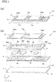
- FIG. 1(a) and FIG. 1(b) are respectively an isometric view and an exploded isometric view of a biosensor 101 in this embodiment.
- the biosensor 101 includes a base substrate 2, an electrode layer 4, first and second reagent layers 6A and 6B, a spacer substrate 8, and a top cover substrate 10.
- the base substrate 2, the spacer substrate 8 and the top cover substrate 8 each have a strip shape and are each longer in a longitudinal direction thereof, which is along an x direction, than in a width direction, which is along a y direction.
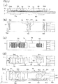
- FIG. 2(a) and FIG. 2(b) are respectively a cross-sectional view and a plan view of the biosensor 101.
- FIG. 2(c), FIG. 2(d) and FIG. 2(e) are respectively a plan view of the biosensor 101 in the state where the top cover substrate 10 is removed, a plan view of the biosensor 101 in the state where the top cover substrate 10 and the first and second reagent layers 6A and 6B are removed, and a plan view of the biosensor 101 in the state where the spacer substrate 8 and components above the spacer substrate 8 are removed.
- FIG. 2(a) and FIG. 2(b) are respectively a cross-sectional view and a plan view of the biosensor 101.
- FIG. 2(c), FIG. 2(d) and FIG. 2(e) are respectively a plan view of the biosensor 101 in the state where the top cover substrate 10 is removed, a plan view of the biosensor 101 in the state where the top cover substrate 10 and the first and second reagent layers 6A and 6B are
- the base substrate 2 supports all the other components of the biosensor 101.
- the base substrate 2 has a main surface 2m and a main surface 2r, and has a strip shape as described above.
- a "main surface” of a substrate is a main large surface by which the substrate supports components.
- the electrode layer 4 is located on the main surface 2m of the base substrate 2.
- the electrode layer 4 includes at least a first electrode pair 4a and a second electrode pair 4b.
- the first electrode pair 4a and the second electrode pair 4b are used to detect a first substance and a second substance, which are different substances contained in a sample.
- the first substance is HbA1c
- the second substance is Hb.
- the first electrode pair 4a includes working electrodes 4aw and counter electrodes 4ac.
- the first electrode pair 4a includes two working electrodes 4aw and three counter electrodes 4ac.
- the two working electrodes 4aw are connected to a terminal 4ed via a line 4dd.
- the three counter electrodes 4ac are connected to a terminal 4ea via a line 4da.
- the working electrodes 4aw and the counter electrodes 4ac are located alternately.
- the second electrode pair 4b includes a working electrode 4bw and counter electrodes 4bc.
- the second electrode pair 4b includes one working electrode 4bw and two counter electrodes 4bc.
- the working electrode 4bw is connected to a terminal 4ec via a line 4dc.
- the two counter electrodes 4bc are connected to a terminal 4eb via a line 4db.
- the working electrode 4bw and the counter electrodes 4bc are located alternately.
- a pair of counter electrodes 4ac having each of the working electrodes 4aw therebetween each have an arcked cut ca.
- the pair of counter electrodes 4bc having the working electrode 4bw therebetween each have an arcked cut cb.
- the above-described structure of the electrodes in the electrode layer 4 is provided by patterning a metal film covering substantially the entirety of the main surface 2m of the base substrate 2.
- the spacer substrate 8 is located on the electrode layer 4, and has a first opening 8a and a second opening 8b formed therein.
- the spacer substrate 8 is shorter than the base substrate 2 in the longitudinal direction. Therefore, the terminals 4ea through 4ed are not covered by the spacer substrate 8 and are exposed.
- the first opening 8a and the second opening 8b are through-holes reaching two main surfaces 8m and 8r of the spacer substrate 8.
- the first opening 8a and the second opening 8b are independent spaces from each other and are not in communication with each other.
- the spacer substrate 8 is provided between the base substrate 2 and the top cover substrate 10, and thus the first opening 8a and the second opening 8b act as reaction chamber holding a sample and detecting an electric change of the sample caused by reactions of the sample with the first reaction layers 6A and 6B.
- the first opening 8a and the second opening 8b each have a rectangular shape having a longitudinal direction in the longitudinal direction of the spacer substrate 8, and are arranged in the longitudinal direction of the spacer substrate 8. Therefore, one end 8ac of the first opening 8a is close to one end 8bc of the second opening 8b at the center or in the vicinity thereof of the spacer substrate 8.
- the other end 8ae of the first opening 8a and the other end 8be of the second opening 8b are respectively close to two ends, in the longitudinal direction, of the spacer substrate 8.
- the first substance in the sample held in the first opening 8a is detected with high sensitivity.
- the reaction chamber provided to detect the first substance has a larger capacity than the capacity of the reaction chamber provided to detect the second substance. Therefore, it is preferable that the first opening 8a has an area size larger than the area size of the second opening 8b. In this embodiment, as shown in FIG.
- the length of the first opening 8a in the x direction (longitudinal direction) is La
- the length of the second opening 8b in the x direction (longitudinal direction) is Lb
- the width of the first opening 8a in the y direction (direction perpendicular to the longitudinal direction) is Wa
- the width of the second opening 8b in the y direction is Wb
- La > Lb and Wa > Wb the amount of the sample that can be held in the first opening 8a may be made larger than the amount of the sample that can be held in the second opening 8b.
- the sizes of the first opening 8a and the second opening 8b may be determined in accordance with the concentrations of the first substance and the second substance in the sample and the required amount of the sample determined in consideration of, for example, the detection sensitivity by the detection method to be used.
- the spacer substrate 8 has a thickness ( z direction) with which the capillary force may act on the sample.
- a part of the first electrode pair 4a and a part of the second electrode pair 4b are respectively exposed to the first opening 8a and the second opening 8b. Electric or electrochemical changes of the sample held in the first opening 8a and the second opening 8b may be respectively detected by the first electrode pair 4a and the second electrode pair 4b.
- a total length of borders between the working electrodes 4aw and the counter electrodes 4ac of the first electrode pair 4a is 4 ⁇ Wa.
- a total length of borders between the working electrode 4bw and the counter electrodes 4bc of the first electrode pair 4b is 2 ⁇ Wb. Namely, the total length of the borders between the working electrode (s) and the counter electrodes is longer in the first electrode pair 4a than in the second electrode pair 4b.
- the first electrode pair 4a has higher detection sensitivity.
- the first reagent layer 6A and the second reagent layer 6B respectively contain a first reagent and a second reagent.
- the first reagent and the second reagent respectively react with the first substance and the second substance in the sample, or with substances derived from the first substance and the second substance by preprocessing, to cause an electrically detectable change to the sample.
- the first reagent is fructosyl peptide oxidase, which is a detection enzyme specifically reactive with fructosyl valyl histidine, which is generated by a preprocess performed on HbA1c, and is immobilized to the first reagent layer.
- the second reagent is potassium ferricyanide, which is a mediator reactive with any type of Hb encompassing HbA1c, and is immobilized to the second reagent layer.
- the first reagent layer 6A and the second reagent layer 6B are respectively located in the first opening 8a and the second opening 8b in the spacer substrate 8. More specifically, the first reagent layer 6A is located above an area in the vicinity of the borders between the working electrodes 4aw and the counter electrodes 4ac of the two first electrode pairs 4a, and the second reagent layer 6B is located above an area in the vicinity of the borders between the working electrode 4bw and the counter electrodes 4bc of the second electrode pair 4b.
- regions in which the materials expand are defined by the arcked cuts ca and cb formed in the counter electrodes.
- the amount of the first reagent layer 6A located in the vicinity of the borders between the working electrodes and the counter electrodes, and the amount of the second reagent layer 6B located in the vicinity of the borders between the working electrode and the counter electrodes, are made the same as each other.
- the level of the electric current is suppressed from being varied between biosensor cells at the time of detection of the first substance and the second substance.
- the top cover substrate 10 is located on the spacer substrate 8.
- the top cover substrate 10 includes an introduction portion having at least one introduction opening formed therein.
- the introduction portion has one introduction opening 10c formed therein.
- the introduction opening 10c overlaps a part of the first opening 8a and a part of the second opening 8b. More specifically, the one end 8ac, in the longitudinal direction, of the first opening 8a and the one end 8bc, in the longitudinal direction, of the second opening 8b are located in the introduction opening 10c. Therefore, the introduction opening 10c is in communication with the first opening 8a and the second opening 8b. When the sample is dropped to the introduction opening 10c, the sample flows into the first opening 8a and the second opening 8b.
- the top cover substrate 10 further has a first discharge opening 10ea and a second discharge opening 10eb formed therein.
- the first discharge opening 10ea and the second discharge opening 10eb respectively overlap a part of the first opening 8a and a part of the second opening 8b.
- the other end 8ae of the first opening 8a and the other end 8be of the second opening 8b are respectively located in the first discharge opening 10ea and the second discharge opening 10eb. Since the first discharge opening 10ea and the second discharge opening 10eb are provided, the following occurs.
- the biosensor 101 is configured such that the capillary force acts on the first opening 8a and the second opening 8b
- gas present in the first opening 8a and the second opening 8b is discharged from the first discharge opening 10ea and the second discharge opening 10eb as the sample is pulled into the first opening 8a and the second opening 8b.
- the sample is introduced into the first opening 8a and the second opening 8b by the capillary force.
- the biosensor 101 is configured such that the capillary force does not substantially act on the first opening 8a or the second opening 8b, neither the first discharge opening 10ea nor the second discharge opening 10eb needs to be provided. In this case, the sample introduced from the introduction opening 10c flows into the first opening 8a and the second opening 8b by the gravity.
- FIG. 1(a) and FIG. 2(a) a first cell 11a having the introduction opening 10c, the first opening 8a and the first discharge opening 10ea formed therein and detecting the first substance, and a second cell 11b having the introduction opening 10c, the second opening 8b and the second discharge opening 10eb formed therein and detecting the second substance, are provided.
- the base substrate 2, the spacer substrate 8 and the top cover substrate 10 are each formed of an insulating material.
- the insulating material for example, any of various resin materials, for example, PET (poly(ethylene terephthalate)) or the like is usable. Instead of such a resin material, an inorganic material such as glass or the like is usable.
- the electrode layer 4 is formed of a conductive material. The electrode layer 4 is formed by patterning a metal film of, for example, palladium or the like with a laser beam or the like.
- the base substrate 2, the electrode layer 4, the spacer substrate 8 and the top cover substrate 10 are bonded together with, for example, an adhesive.
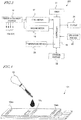
- FIG. 3 shows an example of structure of a measurement device 201 measuring the first substance and the second substance contained in the sample by having the biosensor 101 mounted thereon.
- the measurement device 201 includes a sensor attachment portion 16, a first meter 17, a second meter 18, and a controller 19.
- the sensor attachment portion 16 includes connectors 16a through 16d in contact with the terminals 4ea through 4ed of the biosensor 101 and electrically connected with the first meter 17 and the second meter 18.
- the first meter 17 and the second meter 18 apply a predetermined voltage to the first electrode pair 4a and the second electrode pair 4b via the connectors 16a through 16d and the terminals 4ea through 4ed to measure the current values.
- the measured current values are output to the controller 19.
- the controller 19 determines the concentrations of the first substance and the second substance from the current values (or voltage values) received from the first meter 17 and the second meter 18.
- the controller 19 has, stored thereon, a table showing the relationship between the current values and the concentration values or a function of the current values and the concentration values, and calculates the concentrations of the first substance and the second substance based on the table or the function.
- the first substance is HbAlc and the second substance is Hb.
- the ratio of HbAlc with respect to Hb is calculated based on the current values or the concentration values, and the HbAlc value is determined.
- the measurement device 201 also includes an operation portion 20, a timer 21, a storage portion 22, a temperature sensor 23 and a display 24.
- the measurement device 201 may refer to information from the temperature sensor 23 to correct the HbAlc value.
- the corrected HbAlc value is stored on the storage portion 22 and displayed on the display 24, together with information on the time supplied by the timer 21.
- the controller 19 performs processes such as the measurement, display, storage of the measurement results and the like based on an instruction input by an operator to the operation portion 20.
- the controller 19 of the measurement device 201 includes a computation device such as a microcomputer or the like and a storage portion.
- the storage portion stores a program defining a procedure of the measurement.
- the computation device executes the program, and thus the concentrations of the first substance and the second substance are measured.
- the first meter 17 and the second meter 18 each include a power supply circuit generating a predetermined voltage and a current meter measuring a current value.
- a measured current value is, for example, converted into a digital signal and processed as described above by the controller 19.
- the display 24 may be a liquid crystal display device, an organic EL display device or the like.
- a blood sample obtained from a measurement subject person is preprocessed. Specifically, a hemolytic agent such as a surfactant or the like is added to the obtained blood sample to elute Hb in the erythrocytes in the blood sample.
- a hemolytic agent such as a surfactant or the like is added to the obtained blood sample to elute Hb in the erythrocytes in the blood sample.
- protease which is a degradative enzyme
- HbA1c in Hb generates fructosyl valyl histidine.
- the preprocessed blood sample will be referred to simply as a "sample”.
- the biosensor 101 is attached to the measurement device 201.
- the sample is absorbed by a dropper 30, and as shown in FIG. 4 , is dropped to an area in the vicinity of the introduction opening 10c of the biosensor 101.
- the sample attached to the area in the vicinity of the introduction opening 10c is pulled through the introduction opening 10c by the capillary force and is introduced into the first opening 8a and the second opening 8b at the same time, namely, in parallel to each other.
- Fructosyl valyl histidine in the sample introduced into the first opening 8a reacts with fructosyl peptide oxidase, which is the first reagent contained in the first reagent layer 6A, to generate hydrogen peroxide.
- the conductivity of the sample varies in accordance with the amount of the generated hydrogen peroxide. Therefore, the value of the current flowing between the working electrodes 4aw and the counter electrodes 4ac of the first electrode pair 4a also varies in accordance with the amount of the generated hydrogen peroxide. Since fructosyl valyl histidine is derived from HbA1c, the current value varies in accordance with the amount HbAlc in the sample.
- the movement of charges caused by the oxidation-reduction reaction is detected as a current flowing between the working electrode 4bw and the counter electrodes 4bc of the second electrode pair 4b, and thus the current value in accordance with the amount of Hb is detected.
- a voltage of 0.1 V to 0.4 V is applied by the measurement device 201 for 5 to 10 seconds between the working electrodes 4aw and the counter electrodes 4ac of the first electrode pair 4a, and the amount of the current flowing between the working electrodes 4aw and the counter electrodes 4ac is measured.
- a voltage of 0.1 V to 0.4 V is applied for 5 to 10 seconds between the working electrode 4bw and the counter electrodes 4bc of the second electrode pair 4b, and the amount of the current flowing between the working electrode 4bw and the counter electrodes 4bc is measured.
- the current values measured by the first meter 17 and the second meter 18 respectively correspond to the amount of HbAlc and the amount of Hb.
- the measurement device 201 uses these values to find the HbAlc value.
- FIG. 5 and FIG. 6 show the results of the measurement performed on samples, the concentrations of HbAlc and Hb of which are known.
- the concentrations of HbAlc of the samples are represented by the horizontal axis, and the measured current values are represented by the vertical axis.
- five types of samples, the concentrations of Hb of which were known in advance were used to measure the current values by the second meter 18.
- the concentrations of Hb of the samples are represented by the horizontal axis, and the measured current values are represented by the vertical axis.
- the concentration of HbAlc and the current value have a linear relationship, and the concentration of Hb and the current value also have a linear relationship. It is seen from this that the biosensor 101 of this disclosure is usable to electrochemically measure the concentration of HbAlc and the concentration of Hb and find the HbAlc value with high precision.
- the introduction opening in the top cover substrate overlaps the first opening and the second opening. Therefore, the sample is introduced into the first opening and the second opening in which the electrodes are provided, with no need to provide a flow path including branches for introducing the sample into the reaction chambers. Namely, the biosensor does not include a flow path including branches. Therefore, the area size of the first opening and/or the second opening may be enlarged to increase the amount of the sample used for the measurement, and also the length of the borders between the working electrode(s) and the counter electrodes may be extended. Thus, the detection sensitivity of the biosensor is improved. Since the sample is introduced from the introduction portion, the sample is introduced into the first opening and the second opening provided in the spacer substrate at the same time in parallel to each other. Therefore, the time required to fill the first opening and the second opening with the sample to start the measurement is shortened.
- the sample is reacted with the first substance and the second substance respectively in the first opening and the second opening. Therefore, the two types of substances in the sample are detected or quantified by use of the first electrode pair and the second electrode pair. Since the first opening and the second opening are independent from each other, the measurement on either one of the first substance or the second substance does not influence the measurement on the other substance. The two types of substances are detected independently with high precision.
- the size of each thereof may be set arbitrarily.
- the amounts of the sample to be used for the first opening and the second opening are adjusted independently. Therefore, such amounts of the sample are made different in accordance with the concentrations, to be detected, of the substances in the sample, and also in accordance with the detection sensitivity on each of the substances.
- the measurement is performed with appropriate sensitivity.
- the area size of the first opening may be made larger than that of the second opening, so that the detection precision on the substance to be detected by use of the first substance is improved.
- the area size of the first opening may be made larger than that of the second opening to extend the length of the borders between the working electrodes and the counter electrodes of the first electrode pair, so that the detection sensitivity thereof is further improved.
- the first opening and the second opening are independent from each other. Therefore, in the case where the sample is introduced into the first opening and the second opening by the capillary force, the capillary force acting on each of the first opening and the second opening is independently adjustable.
- the top cover substrate includes the introduction portion. Therefore, the amount of the sample to be dropped may be increased to fill the first opening and the second opening with the sample within a short time. This shortens the measurement time. Even if the area size of each of the first electrode pair and the second electrode pair for the measurement is enlarged, the sample of a sufficient amount is put into contact with the electrode pairs within a short time. This improves the detection sensitivity.
- the first discharge opening and the second discharge opening are provided respectively for the first opening and the second opening. This allows the sample to be introduced into the first opening and the second opening by use of the capillary force. Therefore, the first opening and the second opening are filled with the sample stably and certainly.
- FIG. 7(a) and FIG. 7(b) are respectively an isometric view and an exploded isometric view of a biosensor 102 in this embodiment.
- the top cover substrate 10 includes an introduction portion having a first introduction opening 10ca and a second introduction opening 10cb formed therein.
- the one end 8ac of the first opening 8a is located in the first introduction opening 10ca
- the one end 8bc of the second opening 8b is located in the second introduction opening 10cb.
- the first introduction opening 10ca and the second introduction opening 10cb are independent from each other and are not in communication with each other. Therefore, the area size (size) of each introduction opening is independently adjustable.
- the area sizes of the first introduction opening 10ca and the second introduction opening 10cb respectively overlapping the first opening 8a and the second opening 8b may be varied, so that the magnitudes of the capillary forces acting on the first opening 8a and the second opening 8b are independently adjusted. Even if the first opening 8a and the second opening 8b are different in the area size or the shape, the capillary force acting on each of the first opening 8a and the second opening 8b is adjustable to be appropriate. Thus, the sample is introduced into the biosensor 102 more certainly.
- the first introduction opening 10ca and the second introduction opening 10cb are close to each other. Therefore, for example, the sample, when being dropped to an area between the first introduction opening 10ca and the second introduction opening 10cb, is introduced into both of the first introduction opening 10ca and the second introduction opening 10cb, and thus is introduced into the first opening 8a and the second opening 8b substantially at the same time.
- FIG. 8 is an exploded isometric view of a biosensor 103 in this embodiment.
- the spacer substrate 8 has a first discharge opening 8ad and a second discharge opening 8bd formed therein.
- the first discharge opening 8ad is provided at the other end 8ae of the first opening 8a and has an opening at one side surface, in the longitudinal direction, of the spacer substrate 8.
- the second discharge opening 8bd is provided at the other end 8be of the second opening 8b and has an opening at the other side surface, in the longitudinal direction, of the spacer substrate 8.
- the top cover substrate 10 merely has the introduction opening 10c formed in a main surface thereof. Therefore, it is less possible that any foreign object enters the first discharge opening 10ea or the second discharge opening 10eb or that the operator considers, by mistake, the first discharge opening 10ea or the second discharge opening 10eb as an introduction opening and introduces the sample through the first discharge opening 10ea or the second discharge opening 10eb.
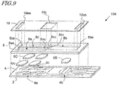
- FIG. 9 is an exploded isometric view of a biosensor 104 in this embodiment.
- the spacer substrate 8 has the first opening 8a, the second opening 8b and a third opening 8c formed therein
- the electrode layer 4 further includes a third electrode pair 4c
- the biosensor 104 includes a third reagent layer 6C.
- the first opening 8a and the third opening 8c are arranged in a direction perpendicular to the longitudinal direction.
- the one end 8ac of the first opening 8a and one end 8cc of the third opening 8c are close to the one end 8bc of the second opening 8b.
- the introduction opening 10c overlaps the one end 8ac of the first opening 8a, the one end 8cc of the third opening 8c and the one end 8bc of the second opening 8b.
- the first discharge opening 10ea overlaps the other end 8ae of the first opening 8a and the other end 8ce of the third opening 8c.
- the third electrode pair 4c is partially exposed to the third opening 8c.
- the third reagent layer 6C is located in the third opening 8c.
- the sample is introduced from the introduction portion of the top cover substrate 10 and thus is introduced into the first opening 8a, the second opening 8b and the third opening 8c provided in the spacer substrate 8 in parallel to each other.
- the third reagent layer 6C may contain a substance reactive with a third substance contained in the sample or a substance derived from the third substance, so that three substances contained in the sample are detected.
- Embodiments 1 through 4 may be combined in an appropriate manner.
- the number of the openings independently provided in the spacer substrate 8 is not limited to two or three, and may be four or greater.
- the sample is not limited to blood or a liquid obtained as a result of blood being preprocessed.
- the first substance and the second substance are not limited to HblAc and Hb. Thus, a biosensor detecting any of various substances is provided.
- a biosensor of this disclosure is preferably usable in the medical and clinical inspection, pharmaceutical manufacturing, or various other industrial fields.
Landscapes
- Health & Medical Sciences (AREA)
- Life Sciences & Earth Sciences (AREA)
- Chemical & Material Sciences (AREA)
- Engineering & Computer Science (AREA)
- Hematology (AREA)
- Molecular Biology (AREA)
- Immunology (AREA)
- Biomedical Technology (AREA)
- Physics & Mathematics (AREA)
- Analytical Chemistry (AREA)
- Biochemistry (AREA)
- General Health & Medical Sciences (AREA)
- Urology & Nephrology (AREA)
- General Physics & Mathematics (AREA)
- Pathology (AREA)
- Microbiology (AREA)
- Biotechnology (AREA)
- Organic Chemistry (AREA)
- Food Science & Technology (AREA)
- Medicinal Chemistry (AREA)
- Cell Biology (AREA)
- Biophysics (AREA)
- Wood Science & Technology (AREA)
- Zoology (AREA)
- Proteomics, Peptides & Aminoacids (AREA)
- Electrochemistry (AREA)
- Chemical Kinetics & Catalysis (AREA)
- Bioinformatics & Cheminformatics (AREA)
- General Engineering & Computer Science (AREA)
- Genetics & Genomics (AREA)
- Ecology (AREA)
- Apparatus Associated With Microorganisms And Enzymes (AREA)
Abstract
Description
- This application relates to a biosensor measuring the concentration of a specific substance contained in a sample.
- Biosensors have been put into practice in various fields including the medical and clinical inspection and pharmaceutical manufacturing. For example, a biosensor measuring the concentration of various substances in the blood has been put into practice and are now widely used in the field of medical and clinical inspection.
-
Patent Document 1 discloses a microfluidic sensor usable as an electrochemical blood test strip for blood coagulation measurement or the like. The microfluidic sensor includes a flow path including branches in which fluids to be measured flow by the capillary action and an electrode pair provided in a reaction zone located at ends of the branches of the flow path.Patent Document 1 discloses that coagulation time is important for blood coagulation measurement and that it is important to minimize the factor preventing the flow of the fluids in the reaction zone in order to perform the measurement with high precision and high reproducibility. - Patent Document 1: Japanese Laid-Open Patent Publication No.
2015-108622 - It is preferable that the structure of a biosensor is optimized for the properties of a subject to be detected and the measurement method used for the detection. This disclosure provides a biosensor using an electrochemical measurement method capable of measuring two or more types of substances more precisely.
- A biosensor of this disclosure includes a base substrate having a main surface; an electrode layer located on the main surface of the base substrate and including a first electrode pair and a second electrode pair each including a working electrode and a counter electrode; a spacer substrate located on the electrode layer and having a first opening and a second opening formed therein, the first opening exposing a part of the first electrode pair and the second opening exposing a part of the second electrode pair, the second opening being independent from the first opening; a first reagent layer containing a first reagent reactive with a sample, the first reagent layer being located in the first opening; a second reagent layer containing a second reagent reactive with the sample, the second reagent layer being located in the second opening; and a top cover substrate located on the spacer substrate, the top cover substrate including an introduction portion having at least one introduction opening formed therein, the introduction portion overlapping a part of the first opening and a part of the second opening in the spacer substrate.
- With the biosensor of this disclosure, the introduction opening in the top cover substrate overlaps the first opening and the second opening. Therefore, the sample is introduced into the first opening and the second opening in which the electrodes are provided, with no need to provide a flow path including branches for introducing the sample into reaction chambers. With such a structure, the area size of the first opening and/or the second opening may be enlarged to increase the amount of the sample used for the measurement, and also the length of a border between the working electrode and the counter electrodes can be extended. Thus, the detection sensitivity of the biosensor is improved. Therefore, two or more types of substances may be measured with high precision by an electrochemical measurement method.
-
-
FIG. 1(a) and FIG. 1(b) are respectively an isometric view and an exploded isometric view of a biosensor inembodiment 1. -
FIG. 2(a) and FIG. 2(b) are respectively a cross-sectional view and a plan view of the biosensor shown inFIG. 1 ;FIG. 2(c) is a plan view of the biosensor in the state where a top cover substrate is removed;FIG. 2(d) is a plan view of the biosensor in the state where the top cover substrate and first and second reagent layers are removed; andFIG. 2(e) is a plan view of the biosensor in the state where a spacer substrate and components above the spacer substrate are removed. -
FIG. 3 is a block diagram showing a structure of a measurement device. -
FIG. 4 is an isometric view showing how a sample is dropped to the biosensor. -
FIG. 5 is a graph showing the relationship between the concentration of HbAlc and the current value in the case where measurement is performed on HbA1c, the concentration of which is known, by use of the biosensor inembodiment 1. -
FIG. 6 is a graph showing the relationship between the concentration of Hb and the current value in the case where measurement is performed on Hb, the concentration of which is known, by use of the biosensor inembodiment 1. -
FIG. 7(a) and FIG. 7(b) are respectively an isometric view and an exploded isometric view of a biosensor inembodiment 2. -
FIG. 8 is an exploded isometric view of a biosensor in embodiment 3. -
FIG. 9 is an exploded isometric view of a biosensor inembodiment 4. - The present inventors studied, in detail, the structure of a biosensor capable of measuring two or more types of substances by an electrochemical measurement method with high precision. It is now assumed that, for example, the value of hemoglobin A1c (hereinafter, referred to as "HbA1c") is to be measured electrochemically by a biosensor. The HbA1c value is an inspection value that shows the ratio of hemoglobin bonded with sugar (HbA1c) with respect to hemoglobin in the erythrocytes (referred to as "Hb") . The HbAlc value reflects an average blood sugar level in the past one to two months, and therefore, is less likely to be influenced by the pre-inspection meal than the blood glucose level and thus is usable as a more accurate index for diabetes control. In order to find the HbAlc value, the concentration (amount) of HbAlc and the concentration (amount) of Hb need to be found. The term "Hb" encompasses HbAlc and all the other derivatives. The concentration of HbA1c is relatively low and thus is difficult to be measured especially electrochemically. Therefore, the HbA1c value has been measured mainly by an optical spectroscopic method.
- In the case where the concentration of the substance to be measured by a biosensor using an electrochemical method is low, it is conceivable to use a maximum possible amount of sample and to enlarge a detection region of the electrode to increase the detection precision. A conventional biosensor detecting two or more types of substances divides the sample into two or more by use of a microfluidic path including branches and detects the substances in the sample in each of reaction chambers by use of an electrochemical reaction. However, the biosensor of such a structure, in which a microfluidic path including branches is formed, may occasionally not allow formation of a large electrode. In light of such a problem, the present inventors conceived a biosensor having a novel structure. The overview of the biosensor in this disclosure is as follows.
- A biosensor, comprising:
- a base substrate having a main surface;
- an electrode layer located on the main surface of the base substrate and including a first electrode pair and a second electrode pair each including a working electrode and a counter electrode;
- a spacer substrate located on the electrode layer and having a first opening and a second opening formed therein, the first opening exposing a part of the first electrode pair and the second opening exposing a part of the second electrode pair, the second opening being independent from the first opening;
- a first reagent layer containing a first reagent reactive with a sample, the first reagent layer being located in the first opening;
- a second reagent layer containing a second reagent reactive with the sample, the second reagent layer being located in the second opening; and
- a top cover substrate located on the spacer substrate, the top cover substrate including an introduction portion having at least one introduction opening formed therein, the introduction portion overlapping a part of the first opening in the spacer substrate and a part of the second opening in the spacer substrate.
- With this structure, the introduction opening in the top cover substrate overlaps the first opening and the second opening. Therefore, the sample is introduced into the first opening and the second opening in which the electrodes are provided, with no need to provide a flow path including branches for introducing the sample into reaction chambers. With such a structure, the area size of the first opening and/or the second opening may be enlarged to increase the amount of the sample used for the measurement, and also the length of a border between the working electrode and the counter electrodes can be extended. Thus, the detection sensitivity of the biosensor is improved. Since the sample is introduced from the introduction portion, the sample is introduced into the first opening and the second opening provided in the spacer substrate at the same time in parallel to each other. Therefore, the time required to fill the first opening and the second opening with the sample to start the measurement is shortened. Since the first opening and the second opening are independent from each other, the size of each thereof may be set arbitrarily. The amounts of the sample to be used for the first opening and the second opening are adjusted independently. Therefore, such amounts of the sample may be made different in accordance with the concentrations, to be detected, of the substances in the sample, and also in accordance with the detection sensitivity on each of the substances. The measurement is performed with appropriate sensitivity.
- The top cover substrate includes the introduction portion. Therefore, the amount of the sample to be dropped may be increased to fill the first opening and the second opening with the sample within a short time. This shortens the measurement time. Even if the area size of each of the first electrode pair and the second electrode pair for the measurement is enlarged, the sample of a sufficient amount is put into contact with the electrode pairs within a short time. This improves the detection sensitivity.
- The biosensor according to
item 1, wherein in the spacer substrate, the first opening has an area size larger than an area size of the second opening. - With this structure, the first opening is large. Therefore, a larger amount of sample may be used for the measurement, and thus the detection precision of the substance to be detected by use of the first substance is improved.
- The biosensor according to
item - With this structure, the length of the border between the working electrode and the counter electrode of the first electrode pair may be extended. This improves the detection sensitivity.
- The biosensor according to
item 1, further comprising a first discharge opening and a second discharge opening respectively in communication with the first opening and the second opening in the spacer substrate. - With this structure, the first discharge opening and the second discharge opening are provided. This allows the sample to be introduced into the first opening and the second opening with certainty by use of the capillary force.
- The biosensor according to
item 4, wherein the first discharge opening and the second discharge opening are provided in the spacer substrate, each have an opening at a side surface of the spacer substrate, and are respectively connected with the first opening and the second opening. - With this structure, the top cover substrate merely has the introduction opening formed in a main surface thereof. Therefore, it is less possible that any foreign object enters the first discharge opening or the second discharge opening or that the operator considers, by mistake, the first discharge opening or the second discharge opening as an introduction opening and introduces the sample through the first discharge opening or the second discharge opening.
- The biosensor according to
item 4, wherein the first discharge opening and the second discharge opening are provided in the top cover substrate and respectively overlap another part of the first opening in the spacer substrate and another part of the second opening in the spacer substrate. - The biosensor according to any one of
items 1 through 6, wherein the introduction portion of the top cover substrate has one introduction opening formed therein, and the introduction opening overlaps the part of the first opening in the spacer substrate and the part of the second opening in the spacer substrate. - With this structure, the sample may be introduced from the introduction opening into the first opening and the second opening at the same time. This simplifies the operation for the measurement.
- The biosensor according to any one of
items 1 through 6, wherein the introduction portion of the top cover substrate has two introduction openings formed therein, one of the introduction openings overlaps the part of the first opening in the spacer substrate, and the other of the introduction openings overlaps the part of the second opening in the spacer substrate. - With this structure, the introduction openings are respectively provided for the first opening and the second opening in the spacer substrate. Therefore, the capillary forces used to introduce the sample into the first opening and the second opening are more easily adjustable independently. Even in the case where the amounts of the sample to be introduced into the first opening and the second opening are increased because of the difference in the detection sensitivity, the time required for the introduction may be made the same, and the sample is allowed to be introduced into the entirety of the first opening and the second opening with certainty. This shortens the measurement time and realizes the measurement with high reproducibility.
- The biosensor according to
item 1, wherein: - the base substrate, the spacer substrate and the top cover substrate each have a strip shape that is longer in a first direction than in a second direction perpendicular to the first direction;
- the first opening and the second opening in the spacer substrate are located adjacent to each other in the first direction; and
- the introduction portion of the top cover substrate has one introduction opening formed therein, and the introduction opening overlaps parts of the first opening and the second opening that are adjacent to each other.
- The biosensor according to item 9, wherein:
- the top cover substrate further has a first discharge opening and a second discharge opening formed therein;
- the first discharge opening and the introduction opening in the introduction portion respectively overlap two ends in the first direction of the first opening in the spacer substrate; and
- the second discharge opening and the introduction opening in the introduction portion respectively overlap two ends in the first direction of the second opening in the spacer substrate.
- The biosensor according to any one of
items 1 through 10, wherein: - the sample contains hemoglobin separated from erythrocytes;
- the hemoglobin contains hemoglobin A1c;
- the first reagent is specifically reactive with the hemoglobin A1c or a substance derived from the hemoglobin A1c; and
- the second reagent is reactive with the hemoglobin.
- Hereinafter, embodiments of a biosensor in this disclosure will be described in detail with reference to the drawings. The biosensor of this disclosure electrochemically detects and/or quantifies two or more different substances contained in a sample. In each of the embodiments of this disclosure, one embodiment of a biosensor detecting a first substance and a second substance contained in the sample will be described. Especially in the case where the detection sensitivities on two or more substances contained in the sample are different, a substance with relatively low detection sensitivity may be detected with improved sensitivity by the biosensor of this disclosure. In the following embodiments, the first substance and the second substance are respectively HbAlc and Hb obtained by a preprocess performed on the blood, and the biosensor electrochemically measures the concentrations of the first substance and the second substance. The biosensor of this disclosure is preferably usable to detect any other appropriate substance. The following embodiments are merely illustrative, and the present invention is not limited to any of the following embodiments. In the following embodiments, components are represented by reference signs in the drawings, and substantially the same descriptions may be omitted or components that are not referred to in the description may not be represented by any reference sign, for easier understanding and or avoidance of unnecessary repetitions.
- A biosensor in
embodiment 1 in this disclosure will be described.FIG. 1(a) and FIG. 1(b) are respectively an isometric view and an exploded isometric view of abiosensor 101 in this embodiment. Thebiosensor 101 includes abase substrate 2, anelectrode layer 4, first and second reagent layers 6A and 6B, aspacer substrate 8, and atop cover substrate 10. As shown inFIG. 1(b) , thebase substrate 2, thespacer substrate 8 and thetop cover substrate 8 each have a strip shape and are each longer in a longitudinal direction thereof, which is along an x direction, than in a width direction, which is along a y direction. -
FIG. 2(a) and FIG. 2(b) are respectively a cross-sectional view and a plan view of thebiosensor 101.FIG. 2(c), FIG. 2(d) and FIG. 2(e) are respectively a plan view of thebiosensor 101 in the state where thetop cover substrate 10 is removed, a plan view of thebiosensor 101 in the state where thetop cover substrate 10 and the first and second reagent layers 6A and 6B are removed, and a plan view of thebiosensor 101 in the state where thespacer substrate 8 and components above thespacer substrate 8 are removed. With reference to these figures, a structure of thebiosensor 101 will be described in detail. - The
base substrate 2 supports all the other components of thebiosensor 101. Thebase substrate 2 has amain surface 2m and amain surface 2r, and has a strip shape as described above. A "main surface" of a substrate is a main large surface by which the substrate supports components. - The
electrode layer 4 is located on themain surface 2m of thebase substrate 2. Theelectrode layer 4 includes at least afirst electrode pair 4a and asecond electrode pair 4b. Thefirst electrode pair 4a and thesecond electrode pair 4b are used to detect a first substance and a second substance, which are different substances contained in a sample. In this embodiment, the first substance is HbA1c, and the second substance is Hb. - As shown in
FIG. 2(e) , thefirst electrode pair 4a includes working electrodes 4aw and counter electrodes 4ac. In this embodiment, thefirst electrode pair 4a includes two working electrodes 4aw and three counter electrodes 4ac. The two working electrodes 4aw are connected to a terminal 4ed via a line 4dd. The three counter electrodes 4ac are connected to a terminal 4ea via a line 4da. In the x direction, which is the longitudinal direction of thebase substrate 2, the working electrodes 4aw and the counter electrodes 4ac are located alternately. - Similarly, the
second electrode pair 4b includes a working electrode 4bw and counter electrodes 4bc. In this embodiment, thesecond electrode pair 4b includes one working electrode 4bw and two counter electrodes 4bc. The working electrode 4bw is connected to a terminal 4ec via a line 4dc. The two counter electrodes 4bc are connected to a terminal 4eb via a line 4db. In the longitudinal direction of thebase substrate 2, the working electrode 4bw and the counter electrodes 4bc are located alternately. A pair of counter electrodes 4ac having each of the working electrodes 4aw therebetween each have an arcked cut ca. Similarly, the pair of counter electrodes 4bc having the working electrode 4bw therebetween each have an arcked cut cb. - In this embodiment, the above-described structure of the electrodes in the
electrode layer 4 is provided by patterning a metal film covering substantially the entirety of themain surface 2m of thebase substrate 2. - The
spacer substrate 8 is located on theelectrode layer 4, and has afirst opening 8a and asecond opening 8b formed therein. Thespacer substrate 8 is shorter than thebase substrate 2 in the longitudinal direction. Therefore, the terminals 4ea through 4ed are not covered by thespacer substrate 8 and are exposed. - The
first opening 8a and thesecond opening 8b are through-holes reaching twomain surfaces spacer substrate 8. Thefirst opening 8a and thesecond opening 8b are independent spaces from each other and are not in communication with each other. Thespacer substrate 8 is provided between thebase substrate 2 and thetop cover substrate 10, and thus thefirst opening 8a and thesecond opening 8b act as reaction chamber holding a sample and detecting an electric change of the sample caused by reactions of the sample with the first reaction layers 6A and 6B. - The
first opening 8a and thesecond opening 8b each have a rectangular shape having a longitudinal direction in the longitudinal direction of thespacer substrate 8, and are arranged in the longitudinal direction of thespacer substrate 8. Therefore, one end 8ac of thefirst opening 8a is close to one end 8bc of thesecond opening 8b at the center or in the vicinity thereof of thespacer substrate 8. The other end 8ae of thefirst opening 8a and the other end 8be of thesecond opening 8b are respectively close to two ends, in the longitudinal direction, of thespacer substrate 8. - In this embodiment, the first substance in the sample held in the
first opening 8a is detected with high sensitivity. Namely, the reaction chamber provided to detect the first substance has a larger capacity than the capacity of the reaction chamber provided to detect the second substance. Therefore, it is preferable that thefirst opening 8a has an area size larger than the area size of thesecond opening 8b. In this embodiment, as shown inFIG. 2(d) , where the length of thefirst opening 8a in the x direction (longitudinal direction) is La, the length of thesecond opening 8b in the x direction (longitudinal direction) is Lb, the width of thefirst opening 8a in the y direction (direction perpendicular to the longitudinal direction) is Wa, and the width of thesecond opening 8b in the y direction (direction perpendicular to the longitudinal direction) is Wb, La > Lb and Wa > Wb. With such an arrangement, the amount of the sample that can be held in thefirst opening 8a may be made larger than the amount of the sample that can be held in thesecond opening 8b. - The sizes of the
first opening 8a and thesecond opening 8b may be determined in accordance with the concentrations of the first substance and the second substance in the sample and the required amount of the sample determined in consideration of, for example, the detection sensitivity by the detection method to be used. In the case where the sample is introduced into thefirst opening 8a and thesecond opening 8b by use of the capillary force (capillary action), thespacer substrate 8 has a thickness (z direction) with which the capillary force may act on the sample. - Since the
spacer substrate 8 is located on theelectrode layer 4, a part of thefirst electrode pair 4a and a part of thesecond electrode pair 4b are respectively exposed to thefirst opening 8a and thesecond opening 8b. Electric or electrochemical changes of the sample held in thefirst opening 8a and thesecond opening 8b may be respectively detected by thefirst electrode pair 4a and thesecond electrode pair 4b. In thefirst opening 8a, a total length of borders between the working electrodes 4aw and the counter electrodes 4ac of thefirst electrode pair 4a is 4 × Wa. In thesecond opening 8b, a total length of borders between the working electrode 4bw and the counter electrodes 4bc of thefirst electrode pair 4b is 2 × Wb. Namely, the total length of the borders between the working electrode (s) and the counter electrodes is longer in thefirst electrode pair 4a than in thesecond electrode pair 4b. Thefirst electrode pair 4a has higher detection sensitivity. - The
first reagent layer 6A and thesecond reagent layer 6B respectively contain a first reagent and a second reagent. The first reagent and the second reagent respectively react with the first substance and the second substance in the sample, or with substances derived from the first substance and the second substance by preprocessing, to cause an electrically detectable change to the sample. In this embodiment, the first reagent is fructosyl peptide oxidase, which is a detection enzyme specifically reactive with fructosyl valyl histidine, which is generated by a preprocess performed on HbA1c, and is immobilized to the first reagent layer. The second reagent is potassium ferricyanide, which is a mediator reactive with any type of Hb encompassing HbA1c, and is immobilized to the second reagent layer. - The
first reagent layer 6A and thesecond reagent layer 6B are respectively located in thefirst opening 8a and thesecond opening 8b in thespacer substrate 8. More specifically, thefirst reagent layer 6A is located above an area in the vicinity of the borders between the working electrodes 4aw and the counter electrodes 4ac of the twofirst electrode pairs 4a, and thesecond reagent layer 6B is located above an area in the vicinity of the borders between the working electrode 4bw and the counter electrodes 4bc of thesecond electrode pair 4b. In this embodiment, in the case where the materials of thefirst reagent layer 6A and thesecond reagent layer 6B are dropped from above theelectrode layer 4, regions in which the materials expand are defined by the arcked cuts ca and cb formed in the counter electrodes. Therefore, the amount of thefirst reagent layer 6A located in the vicinity of the borders between the working electrodes and the counter electrodes, and the amount of thesecond reagent layer 6B located in the vicinity of the borders between the working electrode and the counter electrodes, are made the same as each other. As a result, the level of the electric current is suppressed from being varied between biosensor cells at the time of detection of the first substance and the second substance. - The
top cover substrate 10 is located on thespacer substrate 8. Thetop cover substrate 10 includes an introduction portion having at least one introduction opening formed therein. In this embodiment, the introduction portion has oneintroduction opening 10c formed therein. As well shown inFIG. 2(a) and FIG. 2(b) , the introduction opening 10c overlaps a part of thefirst opening 8a and a part of thesecond opening 8b. More specifically, the one end 8ac, in the longitudinal direction, of thefirst opening 8a and the one end 8bc, in the longitudinal direction, of thesecond opening 8b are located in theintroduction opening 10c. Therefore, theintroduction opening 10c is in communication with thefirst opening 8a and thesecond opening 8b. When the sample is dropped to theintroduction opening 10c, the sample flows into thefirst opening 8a and thesecond opening 8b. - In this embodiment, the
top cover substrate 10 further has a first discharge opening 10ea and a second discharge opening 10eb formed therein. The first discharge opening 10ea and the second discharge opening 10eb respectively overlap a part of thefirst opening 8a and a part of thesecond opening 8b. The other end 8ae of thefirst opening 8a and the other end 8be of thesecond opening 8b are respectively located in the first discharge opening 10ea and the second discharge opening 10eb. Since the first discharge opening 10ea and the second discharge opening 10eb are provided, the following occurs. In the case where thebiosensor 101 is configured such that the capillary force acts on thefirst opening 8a and thesecond opening 8b, gas present in thefirst opening 8a and thesecond opening 8b is discharged from the first discharge opening 10ea and the second discharge opening 10eb as the sample is pulled into thefirst opening 8a and thesecond opening 8b. In this manner, the sample is introduced into thefirst opening 8a and thesecond opening 8b by the capillary force. In the case where thebiosensor 101 is configured such that the capillary force does not substantially act on thefirst opening 8a or thesecond opening 8b, neither the first discharge opening 10ea nor the second discharge opening 10eb needs to be provided. In this case, the sample introduced from the introduction opening 10c flows into thefirst opening 8a and thesecond opening 8b by the gravity. - The above-described components are stacked, and as a result, as shown in
FIG. 1(a) andFIG. 2(a) , afirst cell 11a having theintroduction opening 10c, thefirst opening 8a and the first discharge opening 10ea formed therein and detecting the first substance, and asecond cell 11b having theintroduction opening 10c, thesecond opening 8b and the second discharge opening 10eb formed therein and detecting the second substance, are provided. - The
base substrate 2, thespacer substrate 8 and thetop cover substrate 10 are each formed of an insulating material. As the insulating material, for example, any of various resin materials, for example, PET (poly(ethylene terephthalate)) or the like is usable. Instead of such a resin material, an inorganic material such as glass or the like is usable. Theelectrode layer 4 is formed of a conductive material. Theelectrode layer 4 is formed by patterning a metal film of, for example, palladium or the like with a laser beam or the like. Thebase substrate 2, theelectrode layer 4, thespacer substrate 8 and thetop cover substrate 10 are bonded together with, for example, an adhesive. -
FIG. 3 shows an example of structure of ameasurement device 201 measuring the first substance and the second substance contained in the sample by having thebiosensor 101 mounted thereon. Themeasurement device 201 includes asensor attachment portion 16, afirst meter 17, asecond meter 18, and acontroller 19. Thesensor attachment portion 16 includesconnectors 16a through 16d in contact with the terminals 4ea through 4ed of thebiosensor 101 and electrically connected with thefirst meter 17 and thesecond meter 18. Thefirst meter 17 and thesecond meter 18 apply a predetermined voltage to thefirst electrode pair 4a and thesecond electrode pair 4b via theconnectors 16a through 16d and the terminals 4ea through 4ed to measure the current values. The measured current values are output to thecontroller 19. - The
controller 19 determines the concentrations of the first substance and the second substance from the current values (or voltage values) received from thefirst meter 17 and thesecond meter 18. For example, thecontroller 19 has, stored thereon, a table showing the relationship between the current values and the concentration values or a function of the current values and the concentration values, and calculates the concentrations of the first substance and the second substance based on the table or the function. In this embodiment, the first substance is HbAlc and the second substance is Hb. The ratio of HbAlc with respect to Hb is calculated based on the current values or the concentration values, and the HbAlc value is determined. Themeasurement device 201 also includes anoperation portion 20, atimer 21, astorage portion 22, atemperature sensor 23 and adisplay 24. Themeasurement device 201 may refer to information from thetemperature sensor 23 to correct the HbAlc value. The corrected HbAlc value is stored on thestorage portion 22 and displayed on thedisplay 24, together with information on the time supplied by thetimer 21. Thecontroller 19 performs processes such as the measurement, display, storage of the measurement results and the like based on an instruction input by an operator to theoperation portion 20. - The
controller 19 of themeasurement device 201 includes a computation device such as a microcomputer or the like and a storage portion. The storage portion stores a program defining a procedure of the measurement. The computation device executes the program, and thus the concentrations of the first substance and the second substance are measured. Thefirst meter 17 and thesecond meter 18 each include a power supply circuit generating a predetermined voltage and a current meter measuring a current value. A measured current value is, for example, converted into a digital signal and processed as described above by thecontroller 19. Thedisplay 24 may be a liquid crystal display device, an organic EL display device or the like. - Hereinafter, a specific procedure of measurement performed on HbAlc by use of the
biosensor 101 and themeasurement device 201 will be described. - First, a blood sample obtained from a measurement subject person is preprocessed. Specifically, a hemolytic agent such as a surfactant or the like is added to the obtained blood sample to elute Hb in the erythrocytes in the blood sample.
- Next, protease, which is a degradative enzyme, is added to the blood sample containing the eluted Hb to degrade Hb. As a result of the degradation, HbA1c in Hb generates fructosyl valyl histidine. Hereinafter, the preprocessed blood sample will be referred to simply as a "sample".
- The
biosensor 101 is attached to themeasurement device 201. The sample is absorbed by adropper 30, and as shown inFIG. 4 , is dropped to an area in the vicinity of the introduction opening 10c of thebiosensor 101. The sample attached to the area in the vicinity of theintroduction opening 10c is pulled through the introduction opening 10c by the capillary force and is introduced into thefirst opening 8a and thesecond opening 8b at the same time, namely, in parallel to each other. - Fructosyl valyl histidine in the sample introduced into the
first opening 8a reacts with fructosyl peptide oxidase, which is the first reagent contained in thefirst reagent layer 6A, to generate hydrogen peroxide. The conductivity of the sample varies in accordance with the amount of the generated hydrogen peroxide. Therefore, the value of the current flowing between the working electrodes 4aw and the counter electrodes 4ac of thefirst electrode pair 4a also varies in accordance with the amount of the generated hydrogen peroxide. Since fructosyl valyl histidine is derived from HbA1c, the current value varies in accordance with the amount HbAlc in the sample. - Hb in the sample introduced into the
second opening 8b and potassium ferricyanide, which is the second reagent contained in thesecond reagent layer 6B, cause an oxidation-reduction reaction. The movement of charges caused by the oxidation-reduction reaction is detected as a current flowing between the working electrode 4bw and the counter electrodes 4bc of thesecond electrode pair 4b, and thus the current value in accordance with the amount of Hb is detected. - For example, a voltage of 0.1 V to 0.4 V is applied by the
measurement device 201 for 5 to 10 seconds between the working electrodes 4aw and the counter electrodes 4ac of thefirst electrode pair 4a, and the amount of the current flowing between the working electrodes 4aw and the counter electrodes 4ac is measured. Similarly, a voltage of 0.1 V to 0.4 V is applied for 5 to 10 seconds between the working electrode 4bw and the counter electrodes 4bc of thesecond electrode pair 4b, and the amount of the current flowing between the working electrode 4bw and the counter electrodes 4bc is measured. - The current values measured by the
first meter 17 and thesecond meter 18 respectively correspond to the amount of HbAlc and the amount of Hb. Themeasurement device 201 uses these values to find the HbAlc value. -
FIG. 5 and FIG. 6 show the results of the measurement performed on samples, the concentrations of HbAlc and Hb of which are known. Five types of samples, the concentrations of HbAlc of which were known in advance, were used to measure the current values by thefirst meter 17. In the graph ofFIG. 5 , the concentrations of HbAlc of the samples are represented by the horizontal axis, and the measured current values are represented by the vertical axis. Similarly, five types of samples, the concentrations of Hb of which were known in advance, were used to measure the current values by thesecond meter 18. In the graph ofFIG. 6 , the concentrations of Hb of the samples are represented by the horizontal axis, and the measured current values are represented by the vertical axis. - As seen from
FIG. 5 and FIG. 6 , the concentration of HbAlc and the current value have a linear relationship, and the concentration of Hb and the current value also have a linear relationship. It is seen from this that thebiosensor 101 of this disclosure is usable to electrochemically measure the concentration of HbAlc and the concentration of Hb and find the HbAlc value with high precision. - As described above, in the biosensor of this disclosure, the introduction opening in the top cover substrate overlaps the first opening and the second opening. Therefore, the sample is introduced into the first opening and the second opening in which the electrodes are provided, with no need to provide a flow path including branches for introducing the sample into the reaction chambers. Namely, the biosensor does not include a flow path including branches. Therefore, the area size of the first opening and/or the second opening may be enlarged to increase the amount of the sample used for the measurement, and also the length of the borders between the working electrode(s) and the counter electrodes may be extended. Thus, the detection sensitivity of the biosensor is improved. Since the sample is introduced from the introduction portion, the sample is introduced into the first opening and the second opening provided in the spacer substrate at the same time in parallel to each other. Therefore, the time required to fill the first opening and the second opening with the sample to start the measurement is shortened.
- The sample is reacted with the first substance and the second substance respectively in the first opening and the second opening. Therefore, the two types of substances in the sample are detected or quantified by use of the first electrode pair and the second electrode pair. Since the first opening and the second opening are independent from each other, the measurement on either one of the first substance or the second substance does not influence the measurement on the other substance. The two types of substances are detected independently with high precision.
- Since the first opening and the second opening are independent from each other, the size of each thereof may be set arbitrarily. The amounts of the sample to be used for the first opening and the second opening are adjusted independently. Therefore, such amounts of the sample are made different in accordance with the concentrations, to be detected, of the substances in the sample, and also in accordance with the detection sensitivity on each of the substances. The measurement is performed with appropriate sensitivity. For example, the area size of the first opening may be made larger than that of the second opening, so that the detection precision on the substance to be detected by use of the first substance is improved. The area size of the first opening may be made larger than that of the second opening to extend the length of the borders between the working electrodes and the counter electrodes of the first electrode pair, so that the detection sensitivity thereof is further improved. The first opening and the second opening are independent from each other. Therefore, in the case where the sample is introduced into the first opening and the second opening by the capillary force, the capillary force acting on each of the first opening and the second opening is independently adjustable.
- The top cover substrate includes the introduction portion. Therefore, the amount of the sample to be dropped may be increased to fill the first opening and the second opening with the sample within a short time. This shortens the measurement time. Even if the area size of each of the first electrode pair and the second electrode pair for the measurement is enlarged, the sample of a sufficient amount is put into contact with the electrode pairs within a short time. This improves the detection sensitivity.
- The first discharge opening and the second discharge opening are provided respectively for the first opening and the second opening. This allows the sample to be introduced into the first opening and the second opening by use of the capillary force. Therefore, the first opening and the second opening are filled with the sample stably and certainly.
- A biosensor in
embodiment 2 of this disclosure will be described.FIG. 7(a) and FIG. 7(b) are respectively an isometric view and an exploded isometric view of abiosensor 102 in this embodiment. Unlike in thebiosensor 101 inembodiment 1, in thebiosensor 102, thetop cover substrate 10 includes an introduction portion having a first introduction opening 10ca and a second introduction opening 10cb formed therein. The one end 8ac of thefirst opening 8a is located in the first introduction opening 10ca, and the one end 8bc of thesecond opening 8b is located in the second introduction opening 10cb. The first introduction opening 10ca and the second introduction opening 10cb are independent from each other and are not in communication with each other. Therefore, the area size (size) of each introduction opening is independently adjustable. The area sizes of the first introduction opening 10ca and the second introduction opening 10cb respectively overlapping thefirst opening 8a and thesecond opening 8b may be varied, so that the magnitudes of the capillary forces acting on thefirst opening 8a and thesecond opening 8b are independently adjusted. Even if thefirst opening 8a and thesecond opening 8b are different in the area size or the shape, the capillary force acting on each of thefirst opening 8a and thesecond opening 8b is adjustable to be appropriate. Thus, the sample is introduced into thebiosensor 102 more certainly. - The first introduction opening 10ca and the second introduction opening 10cb are close to each other. Therefore, for example, the sample, when being dropped to an area between the first introduction opening 10ca and the second introduction opening 10cb, is introduced into both of the first introduction opening 10ca and the second introduction opening 10cb, and thus is introduced into the
first opening 8a and thesecond opening 8b substantially at the same time. - A biosensor in embodiment 3 of this disclosure will be described.
FIG. 8 is an exploded isometric view of abiosensor 103 in this embodiment. Unlike in thebiosensor 101 inembodiment 1, in thebiosensor 103, thespacer substrate 8 has a first discharge opening 8ad and a second discharge opening 8bd formed therein. The first discharge opening 8ad is provided at the other end 8ae of thefirst opening 8a and has an opening at one side surface, in the longitudinal direction, of thespacer substrate 8. The second discharge opening 8bd is provided at the other end 8be of thesecond opening 8b and has an opening at the other side surface, in the longitudinal direction, of thespacer substrate 8. - With this structure, the
top cover substrate 10 merely has theintroduction opening 10c formed in a main surface thereof. Therefore, it is less possible that any foreign object enters the first discharge opening 10ea or the second discharge opening 10eb or that the operator considers, by mistake, the first discharge opening 10ea or the second discharge opening 10eb as an introduction opening and introduces the sample through the first discharge opening 10ea or the second discharge opening 10eb. - A biosensor in
embodiment 4 of this disclosure will be described.FIG. 9 is an exploded isometric view of abiosensor 104 in this embodiment. Unlike in thebiosensor 101 inembodiment 1, in thebiosensor 104, thespacer substrate 8 has thefirst opening 8a, thesecond opening 8b and athird opening 8c formed therein, theelectrode layer 4 further includes athird electrode pair 4c, and thebiosensor 104 includes athird reagent layer 6C. Thefirst opening 8a and thethird opening 8c are arranged in a direction perpendicular to the longitudinal direction. The one end 8ac of thefirst opening 8a and one end 8cc of thethird opening 8c are close to the one end 8bc of thesecond opening 8b. Theintroduction opening 10c overlaps the one end 8ac of thefirst opening 8a, the one end 8cc of thethird opening 8c and the one end 8bc of thesecond opening 8b. The first discharge opening 10ea overlaps the other end 8ae of thefirst opening 8a and the other end 8ce of thethird opening 8c. Thethird electrode pair 4c is partially exposed to thethird opening 8c. Thethird reagent layer 6C is located in thethird opening 8c. - With the
biosensor 104, the sample is introduced from the introduction portion of thetop cover substrate 10 and thus is introduced into thefirst opening 8a, thesecond opening 8b and thethird opening 8c provided in thespacer substrate 8 in parallel to each other. Thethird reagent layer 6C may contain a substance reactive with a third substance contained in the sample or a substance derived from the third substance, so that three substances contained in the sample are detected. -
Embodiments 1 through 4 may be combined in an appropriate manner. The number of the openings independently provided in thespacer substrate 8 is not limited to two or three, and may be four or greater. The sample is not limited to blood or a liquid obtained as a result of blood being preprocessed. The first substance and the second substance are not limited to HblAc and Hb. Thus, a biosensor detecting any of various substances is provided. - A biosensor of this disclosure is preferably usable in the medical and clinical inspection, pharmaceutical manufacturing, or various other industrial fields.
-
- 2
- Base substrate
- 2m, 2r, 8m, 8r
- Main surface
- 4
- Electrode layer
- 4a
- First electrode pair
- 4ac, 4bc
- Counter electrode
- 4aw, 4bw
- Working electrode
- 4b
- Second electrode pair
- 4c
- Third electrode pair
- 4da - 4dd
- Line
- 4ea - 4ed
- Terminal
- 6A
- First reagent layer
- 6B
- Second reagent layer
- 6C
- Third reagent layer
- 8
- Spacer substrate
- 8a
- First opening
- 8ac, 8bc, 8cc
- One end
- 8ad
- First discharge opening
- 8ae, 8be, 8ce
- The other end
- 8b
- Second opening
- 8bd
- Second discharge opening
- 8c
- Third opening
- 10
- Top cover substrate
- 10c
- Introduction opening
- 10ca
- First introduction opening
- 10cb
- Second introduction opening
- 10ea
- First discharge opening
- 10eb
- Second discharge opening
- 16
- Sensor attachment portion
- 16a - 16d
- Connector
- 17
- First meter
- 18
- Second meter
- 19
- Controller
- 20
- Operation portion
- 21
- Timer
- 22
- Storage portion
- 23
- Temperature sensor
- 24
- Display
- 30
- Dropper
- 101 - 104
- Biosensor
- 201
- Measurement device
- ca, cb
- Cut
Claims (11)
- A biosensor, comprising:a base substrate having a main surface;an electrode layer located on the main surface of the base substrate and including a first electrode pair and a second electrode pair each including a working electrode and a counter electrode;a spacer substrate located on the electrode layer and having a first opening and a second opening formed therein, the first opening exposing a part of the first electrode pair and the second opening exposing a part of the second electrode pair, the second opening being independent from the first opening;a first reagent layer containing a first reagent reactive with a sample, the first reagent layer being located in the first opening;a second reagent layer containing a second reagent reactive with the sample, the second reagent layer being located in the second opening; anda top cover substrate located on the spacer substrate, the top cover substrate including an introduction portion having at least one introduction opening formed therein, the introduction portion overlapping a part of the first opening in the spacer substrate and a part of the second opening in the spacer substrate.
- The biosensor according to claim 1, wherein in the spacer substrate, the first opening has an area size larger than an area size of the second opening.
- The biosensor according to claim 1 or 2, wherein in the electrode layer, a length of a border between the working electrode and the counter electrode adjacent thereto of the first electrode pair exposed to the first opening is longer than a length of a border between the working electrode and the counter electrode adjacent thereto of the second electrode pair exposed to the second opening.
- The biosensor according to any one of claims 1 through 3, further comprising a first discharge opening and a second discharge opening respectively in communication with the first opening and the second opening in the spacer substrate.
- The biosensor according to claim 4, wherein the first discharge opening and the second discharge opening are provided in the spacer substrate, each have an opening at a side surface of the spacer substrate, and are respectively connected with the first opening and the second opening.
- The biosensor according to claim 4, wherein the first discharge opening and the second discharge opening are provided in the top cover substrate and respectively overlap another part of the first opening in the spacer substrate and another part of the second opening in the spacer substrate.
- The biosensor according to any one of claims 1 through 6, wherein the introduction portion of the top cover substrate has one introduction opening formed therein, and the introduction opening overlaps the part of the first opening in the spacer substrate and the part of the second opening in the spacer substrate.
- The biosensor according to any one of claims 1 through 6, wherein the introduction portion of the top cover substrate has two introduction openings formed therein, one of the introduction openings overlaps the part of the first opening in the spacer substrate, and the other of the introduction openings overlaps the part of the second opening in the spacer substrate.
- The biosensor according to any one of claims 1 through 3, wherein:the base substrate, the spacer substrate and the top cover substrate each have a strip shape that is longer in a first direction than in a second direction perpendicular to the first direction;the first opening and the second opening in the spacer substrate are located adjacent to each other in the first direction; andthe introduction portion of the top cover substrate has one introduction opening formed therein, and the introduction opening overlaps parts of the first opening and the second opening that are adjacent to each other.
- The biosensor according to claim 9, wherein:the top cover substrate further has a first discharge opening and a second discharge opening formed therein;the first discharge opening and the introduction opening in the introduction portion respectively overlap two ends in the first direction of the first opening in the spacer substrate; andthe second discharge opening and the introduction opening in the introduction portion respectively overlap two ends in the first direction of the second opening in the spacer substrate.
- The biosensor according to any one of claims 1 through 10, wherein:the sample contains hemoglobin separated from erythrocytes;the hemoglobin contains hemoglobin A1c;the first reagent is specifically reactive with the hemoglobin A1c or a substance derived from the hemoglobin A1c; andthe second reagent is reactive with the hemoglobin.
Applications Claiming Priority (2)
| Application Number | Priority Date | Filing Date | Title |
|---|---|---|---|
| JP2016034671 | 2016-02-25 | ||
| PCT/JP2016/077154 WO2017145420A1 (en) | 2016-02-25 | 2016-09-14 | Biosensor |
Publications (2)
| Publication Number | Publication Date |
|---|---|
| EP3454056A1 true EP3454056A1 (en) | 2019-03-13 |
| EP3454056A4 EP3454056A4 (en) | 2019-06-26 |
Family
ID=59686062
Family Applications (1)
| Application Number | Title | Priority Date | Filing Date |
|---|---|---|---|
| EP16891576.7A Withdrawn EP3454056A4 (en) | 2016-02-25 | 2016-09-14 | Biosensor |
Country Status (4)
| Country | Link |
|---|---|
| US (1) | US20190017957A1 (en) |
| EP (1) | EP3454056A4 (en) |
| JP (1) | JP6126325B1 (en) |
| WO (1) | WO2017145420A1 (en) |
Families Citing this family (4)
| Publication number | Priority date | Publication date | Assignee | Title |
|---|---|---|---|---|
| WO2019010152A1 (en) * | 2017-07-03 | 2019-01-10 | Arch Chemicals, Inc. | Sensor for analytes |
| WO2019187575A1 (en) * | 2018-03-26 | 2019-10-03 | Phcホールディングス株式会社 | Biological substance detection sensor |
| CN121476329A (en) * | 2018-11-08 | 2026-02-06 | 利多(香港)有限公司 | Biosensors and detection methods for urea detection |
| EP3926338A4 (en) * | 2019-02-15 | 2022-03-30 | PHC Holdings Corporation | BIOSENSOR |
Family Cites Families (36)
| Publication number | Priority date | Publication date | Assignee | Title |
|---|---|---|---|---|
| WO1989009397A1 (en) * | 1988-03-31 | 1989-10-05 | Matsushita Electric Industrial Co., Ltd. | Biosensor and process for its production |
| JPH0658338B2 (en) * | 1988-05-18 | 1994-08-03 | 松下電器産業株式会社 | Biosensor |
| JP3441993B2 (en) * | 1999-01-27 | 2003-09-02 | 松下電器産業株式会社 | Cholesterol sensor |
| US20150344929A9 (en) * | 1999-11-15 | 2015-12-03 | Panasonic Corporation | Biosensor, thin film electrode forming method, quantification apparatus, and quantification method |
| EP1281955B1 (en) * | 2001-04-16 | 2013-06-05 | Panasonic Corporation | Biosensor |
| US7005273B2 (en) * | 2001-05-16 | 2006-02-28 | Therasense, Inc. | Method for the determination of glycated hemoglobin |
| AU2003259038A1 (en) * | 2002-06-19 | 2004-01-06 | Becton, Dickinson And Company | Microfabricated sensor arrays |
| EP1396717A1 (en) * | 2002-09-03 | 2004-03-10 | Matsushita Electric Industrial Co., Ltd. | Biosensor and measuring method using the same |
| JP4100196B2 (en) * | 2003-02-27 | 2008-06-11 | 松下電器産業株式会社 | Biosensor |
| EP1642125B1 (en) * | 2003-06-20 | 2017-09-27 | Roche Diabetes Care GmbH | Biosensor with multiple electrical functionalities |
| US8071030B2 (en) * | 2003-06-20 | 2011-12-06 | Roche Diagnostics Operations, Inc. | Test strip with flared sample receiving chamber |
| US7622026B2 (en) * | 2004-03-02 | 2009-11-24 | Panasonic Corporation | Biosensor |
| US8372600B2 (en) * | 2004-03-05 | 2013-02-12 | The Research Foundation Of State University Of New York | Method and apparatus for measuring changes in cell volume |
| JP2005283192A (en) * | 2004-03-29 | 2005-10-13 | Citizen Watch Co Ltd | Biosensor |
| EP1742045B1 (en) * | 2004-04-19 | 2016-11-02 | Panasonic Healthcare Holdings Co., Ltd. | Method for measuring blood components and biosensor and measuring instrument for use therein |
| WO2007094354A1 (en) * | 2006-02-14 | 2007-08-23 | National Institute Of Advanced Industrial Science And Technology | HEMOGLOBIN A1c SENSOR |
| US20080083618A1 (en) * | 2006-09-05 | 2008-04-10 | Neel Gary T | System and Methods for Determining an Analyte Concentration Incorporating a Hematocrit Correction |
| US7674616B2 (en) * | 2006-09-14 | 2010-03-09 | Hemosense, Inc. | Device and method for measuring properties of a sample |
| JP2008076143A (en) * | 2006-09-20 | 2008-04-03 | Citizen Holdings Co Ltd | Instrument for measuring hemoglobin concentration |
| JPWO2008044530A1 (en) * | 2006-10-05 | 2010-02-12 | パナソニック株式会社 | Multi-item component analysis sensor and multi-item component measurement method |
| CA2693497A1 (en) * | 2007-07-31 | 2009-02-05 | Bayer Healthcare Llc | Test sensors and method of using side-mounted meter contacts |
| TW200914826A (en) * | 2007-09-21 | 2009-04-01 | Apex Biotechnology Corp | Electrochemical quantitative analysis system and method for the same |
| CN107576707B (en) * | 2007-09-24 | 2020-03-13 | 安晟信医疗科技控股公司 | Analyte test sensor, system thereof and method for measuring at least one analyte |
| EP2211171A4 (en) * | 2007-11-05 | 2014-04-16 | Nippon Kayaku Kk | Biosensor |
| EP2283149A1 (en) * | 2008-05-13 | 2011-02-16 | General Atomics | Electrochemical biosensor for direct determination of percentage of glycated hemoglobin |
| JP5405916B2 (en) * | 2008-06-24 | 2014-02-05 | パナソニック株式会社 | Biosensor, method for manufacturing the same, and detection system including the same |
| EP2387714B1 (en) * | 2009-01-23 | 2018-03-14 | Polymer Technology Systems, Inc. | Diagnostic multi-layer dry phase test strip with integrated biosensors |
| CN102608196A (en) * | 2011-01-18 | 2012-07-25 | 爱科来株式会社 | Analysis deviceand analysis method |
| US8702931B2 (en) * | 2011-04-18 | 2014-04-22 | Indian Institute Of Science | Low cost electrochemical disposable sensor for measuring glycated hemoglobin |
| JP5730396B2 (en) * | 2011-07-28 | 2015-06-10 | 京セラ株式会社 | Biosensor |
| US8603309B2 (en) * | 2011-09-12 | 2013-12-10 | Nova Biomedical Corporation | Disposable sensor for electrochemical detection of hemoglobin |
| US20130084591A1 (en) * | 2011-09-30 | 2013-04-04 | Lifescan Scotland Ltd. | Analytical test strip with isolated bodily fluid phase-shift and analyte determination sample chambers |
| US9128038B2 (en) * | 2012-06-21 | 2015-09-08 | Lifescan Scotland Limited | Analytical test strip with capillary sample-receiving chambers separated by a physical barrier island |
| JP2014102144A (en) * | 2012-11-20 | 2014-06-05 | Nipro Corp | Glycosylated hemoglobin measuring kit and glycosylated hemoglobin measuring method |
| TWI477772B (en) * | 2013-02-25 | 2015-03-21 | Apex Biotechnology Corp | Electrode strip and sensor strip and system thereof |
| US20140262833A1 (en) * | 2013-03-14 | 2014-09-18 | Magellan Diagnostics, Inc. | Sensor with a bifurcated flowpath |
-
2016
- 2016-09-14 EP EP16891576.7A patent/EP3454056A4/en not_active Withdrawn
- 2016-09-14 WO PCT/JP2016/077154 patent/WO2017145420A1/en not_active Ceased
- 2016-09-14 JP JP2017509798A patent/JP6126325B1/en active Active
-
2018
- 2018-08-24 US US16/111,882 patent/US20190017957A1/en not_active Abandoned
Also Published As
| Publication number | Publication date |
|---|---|
| US20190017957A1 (en) | 2019-01-17 |
| JP6126325B1 (en) | 2017-05-10 |
| EP3454056A4 (en) | 2019-06-26 |
| WO2017145420A1 (en) | 2017-08-31 |
| JPWO2017145420A1 (en) | 2018-03-08 |
Similar Documents
| Publication | Publication Date | Title |
|---|---|---|
| KR101854883B1 (en) | Apparatus and method for electrochemical detection | |
| ES2657627T3 (en) | Electrochemical biosensors | |
| CN101517402B (en) | Method of making a calibrated analyte sensor | |
| EP2568281B1 (en) | Disposable sensor for electrochemical detection of hemoglobin | |
| JP6539369B2 (en) | Normalized calibration of analyte concentration determination | |
| EP2284526B1 (en) | Biosensor system and method of measuring analyte concentration in blood sample | |
| US20140202881A1 (en) | Electrochemical Biosensor | |
| EP3926338A1 (en) | Biosensor | |
| TWI624666B (en) | System error compensation of analyte concentration determinations | |
| US20190017957A1 (en) | Biosensor | |
| EP2900138B1 (en) | System and method for determining hematocrit insensitive glucose concentration | |
| KR102083979B1 (en) | Sensor strip and Apparatus for measuring biomaterial using the sensor strip | |
| TWI621852B (en) | Progressive approximation of sample analyte concentration | |
| US20230305026A1 (en) | Systems and methods for electrochemical point-of-care detection of hemoglobin | |
| EP2297574B1 (en) | Bio-sensor | |
| HK1181850A1 (en) | Slope-based compensation including secondary output signals | |
| HK1181850B (en) | Slope-based compensation including secondary output signals |
Legal Events
| Date | Code | Title | Description |
|---|---|---|---|
| STAA | Information on the status of an ep patent application or granted ep patent |
Free format text: STATUS: THE INTERNATIONAL PUBLICATION HAS BEEN MADE |
|
| PUAI | Public reference made under article 153(3) epc to a published international application that has entered the european phase |
Free format text: ORIGINAL CODE: 0009012 |
|
| STAA | Information on the status of an ep patent application or granted ep patent |
Free format text: STATUS: REQUEST FOR EXAMINATION WAS MADE |
|
| 17P | Request for examination filed |
Effective date: 20181204 |
|
| AK | Designated contracting states |
Kind code of ref document: A1 Designated state(s): AL AT BE BG CH CY CZ DE DK EE ES FI FR GB GR HR HU IE IS IT LI LT LU LV MC MK MT NL NO PL PT RO RS SE SI SK SM TR |
|
| AX | Request for extension of the european patent |
Extension state: BA ME |
|
| DAV | Request for validation of the european patent (deleted) | ||
| DAX | Request for extension of the european patent (deleted) | ||
| A4 | Supplementary search report drawn up and despatched |
Effective date: 20190524 |
|
| RIC1 | Information provided on ipc code assigned before grant |
Ipc: C12Q 1/00 20060101ALI20190520BHEP Ipc: G01N 27/416 20060101ALI20190520BHEP Ipc: G01N 27/327 20060101AFI20190520BHEP Ipc: G01N 33/72 20060101ALI20190520BHEP |
|
| STAA | Information on the status of an ep patent application or granted ep patent |
Free format text: STATUS: EXAMINATION IS IN PROGRESS |
|
| 17Q | First examination report despatched |
Effective date: 20210916 |
|
| STAA | Information on the status of an ep patent application or granted ep patent |
Free format text: STATUS: THE APPLICATION HAS BEEN WITHDRAWN |
|
| 18W | Application withdrawn |
Effective date: 20211207 |