EP3453983A1 - Spa bath tub with heat pump and heat pump therefore - Google Patents
Spa bath tub with heat pump and heat pump therefore Download PDFInfo
- Publication number
- EP3453983A1 EP3453983A1 EP18250018.1A EP18250018A EP3453983A1 EP 3453983 A1 EP3453983 A1 EP 3453983A1 EP 18250018 A EP18250018 A EP 18250018A EP 3453983 A1 EP3453983 A1 EP 3453983A1
- Authority
- EP
- European Patent Office
- Prior art keywords
- heat pump
- water
- air
- spa bath
- heat
- Prior art date
- Legal status (The legal status is an assumption and is not a legal conclusion. Google has not performed a legal analysis and makes no representation as to the accuracy of the status listed.)
- Withdrawn
Links
Images




Classifications
-
- F—MECHANICAL ENGINEERING; LIGHTING; HEATING; WEAPONS; BLASTING
- F24—HEATING; RANGES; VENTILATING
- F24H—FLUID HEATERS, e.g. WATER OR AIR HEATERS, HAVING HEAT-GENERATING MEANS, e.g. HEAT PUMPS, IN GENERAL
- F24H1/00—Water heaters, e.g. boilers, continuous-flow heaters or water-storage heaters
- F24H1/0072—Special adaptations
-
- A—HUMAN NECESSITIES
- A47—FURNITURE; DOMESTIC ARTICLES OR APPLIANCES; COFFEE MILLS; SPICE MILLS; SUCTION CLEANERS IN GENERAL
- A47K—SANITARY EQUIPMENT; ACCESSORIES THEREFOR, e.g. TOILET ACCESSORIES
- A47K3/00—Baths; Showers; Appurtenances therefor
- A47K3/02—Baths
- A47K3/08—Cabinet baths
-
- A—HUMAN NECESSITIES
- A61—MEDICAL OR VETERINARY SCIENCE; HYGIENE
- A61H—PHYSICAL THERAPY APPARATUS, e.g. DEVICES FOR LOCATING OR STIMULATING REFLEX POINTS IN THE BODY; ARTIFICIAL RESPIRATION; MASSAGE; BATHING DEVICES FOR SPECIAL THERAPEUTIC OR HYGIENIC PURPOSES OR SPECIFIC PARTS OF THE BODY
- A61H33/00—Bathing devices for special therapeutic or hygienic purposes
- A61H33/0087—Therapeutic baths with agitated or circulated water
-
- A—HUMAN NECESSITIES
- A61—MEDICAL OR VETERINARY SCIENCE; HYGIENE
- A61H—PHYSICAL THERAPY APPARATUS, e.g. DEVICES FOR LOCATING OR STIMULATING REFLEX POINTS IN THE BODY; ARTIFICIAL RESPIRATION; MASSAGE; BATHING DEVICES FOR SPECIAL THERAPEUTIC OR HYGIENIC PURPOSES OR SPECIFIC PARTS OF THE BODY
- A61H33/00—Bathing devices for special therapeutic or hygienic purposes
- A61H33/0095—Arrangements for varying the temperature of the liquid
-
- A—HUMAN NECESSITIES
- A61—MEDICAL OR VETERINARY SCIENCE; HYGIENE
- A61H—PHYSICAL THERAPY APPARATUS, e.g. DEVICES FOR LOCATING OR STIMULATING REFLEX POINTS IN THE BODY; ARTIFICIAL RESPIRATION; MASSAGE; BATHING DEVICES FOR SPECIAL THERAPEUTIC OR HYGIENIC PURPOSES OR SPECIFIC PARTS OF THE BODY
- A61H33/00—Bathing devices for special therapeutic or hygienic purposes
- A61H33/60—Components specifically designed for the therapeutic baths of groups A61H33/00
-
- F—MECHANICAL ENGINEERING; LIGHTING; HEATING; WEAPONS; BLASTING
- F24—HEATING; RANGES; VENTILATING
- F24H—FLUID HEATERS, e.g. WATER OR AIR HEATERS, HAVING HEAT-GENERATING MEANS, e.g. HEAT PUMPS, IN GENERAL
- F24H1/00—Water heaters, e.g. boilers, continuous-flow heaters or water-storage heaters
- F24H1/54—Water heaters for bathtubs or pools; Water heaters for reheating the water in bathtubs or pools
-
- F—MECHANICAL ENGINEERING; LIGHTING; HEATING; WEAPONS; BLASTING
- F24—HEATING; RANGES; VENTILATING
- F24H—FLUID HEATERS, e.g. WATER OR AIR HEATERS, HAVING HEAT-GENERATING MEANS, e.g. HEAT PUMPS, IN GENERAL
- F24H4/00—Fluid heaters characterised by the use of heat pumps
- F24H4/02—Water heaters
-
- F—MECHANICAL ENGINEERING; LIGHTING; HEATING; WEAPONS; BLASTING
- F24—HEATING; RANGES; VENTILATING
- F24H—FLUID HEATERS, e.g. WATER OR AIR HEATERS, HAVING HEAT-GENERATING MEANS, e.g. HEAT PUMPS, IN GENERAL
- F24H9/00—Details
- F24H9/02—Casings; Cover lids; Ornamental panels
-
- A—HUMAN NECESSITIES
- A61—MEDICAL OR VETERINARY SCIENCE; HYGIENE
- A61H—PHYSICAL THERAPY APPARATUS, e.g. DEVICES FOR LOCATING OR STIMULATING REFLEX POINTS IN THE BODY; ARTIFICIAL RESPIRATION; MASSAGE; BATHING DEVICES FOR SPECIAL THERAPEUTIC OR HYGIENIC PURPOSES OR SPECIFIC PARTS OF THE BODY
- A61H2201/00—Characteristics of apparatus not provided for in the preceding codes
- A61H2201/02—Characteristics of apparatus not provided for in the preceding codes heated or cooled
- A61H2201/0207—Characteristics of apparatus not provided for in the preceding codes heated or cooled heated
-
- A—HUMAN NECESSITIES
- A61—MEDICAL OR VETERINARY SCIENCE; HYGIENE
- A61H—PHYSICAL THERAPY APPARATUS, e.g. DEVICES FOR LOCATING OR STIMULATING REFLEX POINTS IN THE BODY; ARTIFICIAL RESPIRATION; MASSAGE; BATHING DEVICES FOR SPECIAL THERAPEUTIC OR HYGIENIC PURPOSES OR SPECIFIC PARTS OF THE BODY
- A61H2201/00—Characteristics of apparatus not provided for in the preceding codes
- A61H2201/02—Characteristics of apparatus not provided for in the preceding codes heated or cooled
- A61H2201/0221—Mechanism for heating or cooling
-
- A—HUMAN NECESSITIES
- A61—MEDICAL OR VETERINARY SCIENCE; HYGIENE
- A61H—PHYSICAL THERAPY APPARATUS, e.g. DEVICES FOR LOCATING OR STIMULATING REFLEX POINTS IN THE BODY; ARTIFICIAL RESPIRATION; MASSAGE; BATHING DEVICES FOR SPECIAL THERAPEUTIC OR HYGIENIC PURPOSES OR SPECIFIC PARTS OF THE BODY
- A61H2201/00—Characteristics of apparatus not provided for in the preceding codes
- A61H2201/02—Characteristics of apparatus not provided for in the preceding codes heated or cooled
- A61H2201/0221—Mechanism for heating or cooling
- A61H2201/0242—Mechanism for heating or cooling by a fluid circulating in the apparatus
-
- A—HUMAN NECESSITIES
- A61—MEDICAL OR VETERINARY SCIENCE; HYGIENE
- A61H—PHYSICAL THERAPY APPARATUS, e.g. DEVICES FOR LOCATING OR STIMULATING REFLEX POINTS IN THE BODY; ARTIFICIAL RESPIRATION; MASSAGE; BATHING DEVICES FOR SPECIAL THERAPEUTIC OR HYGIENIC PURPOSES OR SPECIFIC PARTS OF THE BODY
- A61H2201/00—Characteristics of apparatus not provided for in the preceding codes
- A61H2201/50—Control means thereof
- A61H2201/5007—Control means thereof computer controlled
-
- A—HUMAN NECESSITIES
- A61—MEDICAL OR VETERINARY SCIENCE; HYGIENE
- A61H—PHYSICAL THERAPY APPARATUS, e.g. DEVICES FOR LOCATING OR STIMULATING REFLEX POINTS IN THE BODY; ARTIFICIAL RESPIRATION; MASSAGE; BATHING DEVICES FOR SPECIAL THERAPEUTIC OR HYGIENIC PURPOSES OR SPECIFIC PARTS OF THE BODY
- A61H2201/00—Characteristics of apparatus not provided for in the preceding codes
- A61H2201/50—Control means thereof
- A61H2201/5058—Sensors or detectors
- A61H2201/5082—Temperature sensors
-
- F—MECHANICAL ENGINEERING; LIGHTING; HEATING; WEAPONS; BLASTING
- F24—HEATING; RANGES; VENTILATING
- F24D—DOMESTIC- OR SPACE-HEATING SYSTEMS, e.g. CENTRAL HEATING SYSTEMS; DOMESTIC HOT-WATER SUPPLY SYSTEMS; ELEMENTS OR COMPONENTS THEREFOR
- F24D2200/00—Heat sources or energy sources
- F24D2200/12—Heat pump
-
- F—MECHANICAL ENGINEERING; LIGHTING; HEATING; WEAPONS; BLASTING
- F24—HEATING; RANGES; VENTILATING
- F24H—FLUID HEATERS, e.g. WATER OR AIR HEATERS, HAVING HEAT-GENERATING MEANS, e.g. HEAT PUMPS, IN GENERAL
- F24H9/00—Details
- F24H9/0052—Details for air heaters
- F24H9/0073—Arrangement or mounting of means for forcing the circulation of air
Definitions
- This invention relates to a spa bath including a heat pump operable to heat water in the bath.
- spa bath refers to a facility including a tub of water, usually aerated and circulated, to accommodate one or more people for rest and recreation or possibly therapeutic purposes. It shall be deemed herein to include hot tubs, swimming pools, plunge pools and ice baths.
- the present invention can be directed to that end, and also to heating water in a swimming pool.
- users may require the water to be cooled, and the present invention can be adapted to meet that requirement as well.
- the invention is particularly but not exclusively applicable to spa baths installed in substantial numbers in leisure parks or caravan sites where it is necessary for each resident to have individual control of the operation and cost (typically by rental) of an allocated spa bath. It may also be applied to spa baths for use in individual domestic properties.
- Heaters for the water may be of various forms, including wood-fired or gas-fired heaters and solar collectors, but are mostly electrical, usually some kind of through-flow heater or some kind of heat pump. Cooling is usually done by refrigeration (essentially a heat pump run in reverse) although for cold immersion therapy ice may be physically added to the water.
- Heat pumps are efficient but heretofore it has proved difficult to make them compact enough for heating water specifically for a spa bath.
- Household-scale installations are known from, for instance, Chinese Utility Models CN202008223 , CN201787665 and CN2802345 and French Patent Application FR2382656 .
- a spa bath requires a much more compact installation, especially where this needs to be individually operated and controlled, as where multiple spa baths are installed in a leisure park.
- Compactness is also important for aesthetic reasons, as users of individual spa baths would likely be discomfited by large scale heating plant in the immediate vicinity.
- a heat pump installation including a heat pump operable by way of a control system to heat water for a spa bath, wherein the heat pump utilises a working fluid circulated on a fluid path including - an evaporator for the working fluid; a fan operative to pass ambient air through airways in the evaporator to transfer heat to and thereby evaporate the working fluid; a compressor for the heated working fluid; and a condenser for the heated and compressed working fluid configured and arranged to transfer heat from the working fluid to the water; characterised in that:
- the invention extends to a spa bath including the heat pump installation together with a tub for the water and a thermally insulative cabinet for the tub, characterised in that the heat pump installation is configured and arranged for installation within the cabinet and to use therein the ambient air as its source of heat.
- FIG. 1 this shows a heat pump system 100 operative (by means which will be well understood by those skilled in the art) to extract heat Qo from a source 102 using a working fluid such as the hydrofluorocarbon R 407 C which is evaporated at the source 102.
- a working fluid such as the hydrofluorocarbon R 407 C which is evaporated at the source 102.
- the temperature of the source 102 is decreased and the temperature of the working fluid is increased.
- the working fluid is compressed - that is to say, work W is done on the system - and as a result the temperature of the working fluid is further increased.
- the working fluid is fed to the sink 104, delivering heat Qi to the sink 104.
- the sink 104 is heated, and the working fluid id condensed back to a liquid state.
- the condensed working fluid is recirculated back to the source 102 so that the cycle may continue.
- the system of Figure 1 may be used for heating or for cooling.
- a heat pump installation may be used to heat water in a spa bath, its efficiency being measured by the coefficient of performance (Qo + W)/W.
- the coefficient of performance is greater than 1, meaning that a heat pump is necessarily more efficient than a straightforward electric heater.
- the system extracts heat Qo from a source 102 such as water and discharges it to a sink 104 such as the surrounding air.
- a heat pump installation may be used to cool water in a spa bath, its efficiency being measured by the coefficient of performance Qo/W.
- a heat pump installation associated with a spa bath may be used to heat water in the tub, which will be the commonest mode of operation in temperate climate zone, or it may effectively be run in reverse to cool the water in the tub.
- a system in heating mode as those skilled in the art will be readily able to envisage its operation in cooling mode.
- this illustrates a spa bath comprising a tub 200 seated in and supported by a thermally insulative cabinet 202 indicated in broken lines.
- a heat pump installation within the cabinet is used to heat water in the tub 202.
- a water pump 204 pumps water around a circuit including the tub 200, as indicated by the arrows A and B.
- the circuit includes a through-flow electric heater 206 operable to heat the water fed to the tub 200 at A.
- a heat pump 210 which also heats the water fed to the tub at A. The hot water at A is fed into and across the tub and thereafter exits at B and passes through a filter 212 and thence around the circuit again.
- the heat pump 210 is an air source heat pump working within the cabinet to draw heat from ambient air.
- the presence of the electric heater 206 should not be taken as an indication that the heat pump 210 may not be able to heat the water adequately. Rather, the electric heater has an important ancillary function.
- Holiday complexes such as leisure parks are commonly provided with large numbers of spa baths associated with cabins, caravans or the like rented by holidaymakers, typically on a weekly basis with a specified changeover day. On changeover day it is necessary among other things to drain each spa bath, clean it, refill it with water and bring the water up to operating temperature before the new occupants arrive. This last task is especially challenging because it requires a minimum amount of time, and the electric heater 206 ensures that it can be met.
- the electric heater 206 can be switched off (eg under the control of a thermostat) and the temperature can be maintained by the heat pump 210.
- the invention provides economical heating during normal operation and fast heating during changeover periods.
- Figure 3 shows a spa bath comprising a tub 300 for water seated in and supported by a thermally insulative cabinet 302.
- the cabinet 302 which has a lid 304 (shown raised in Figure 3 ) for retaining heat in the water when the spa bath is not in use, is not much deeper than the tub 300. Comparing Figure 3 with Figure 2 , it should be understood that Figure 2 exaggerates the depth of the cabinet 202, for clarity of illustration. In practice the relative depths of the tub 200 and the cabinet 202 will be similar to those depicted in Figure 3 .
- the heat pump installation of a spa bath comprises utilizes air:water heat pump technology and comprises, referring to Figure 4 , a compressor 400, a tubular condenser 402, a heat pump system 404, a drier filter 406, an expansion valve 408, a selectively operable solenoid valve 410, an overpressure centrifugal fan 412 and a finned coil heat exchanger 414, all interconnected by a circuit 416 around which working fluid flows as indicated by the arrow C and contained within a housing 418 formed with inlets and outlets for air and water.
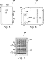
- Figures 5 to 8 show an improved heat pump installation 500 for a spa bath like that of Figures 2 to 4 .
- Figure 5 shows the heat pump installation 500 in front elevation
- Figure 6 in side elevation
- Figure 7 in rear elevation
- Figure 8 is an isometric view showing the arrangement of the heat pump illustration 500 within its casing 502.
- a fan 504 ( Figure 8 ) at one side of the casing 502 draws ambient air A endways into the casing 502 through an air inlet 506 at the rear end of the casing 502.
- the air inlet 506 extends substantially wholly across the rear end of the housing 502, from side to side and from top to bottom, and this maximised cross-section of the air inlet 506 allows the greatest possible amount of air A to be drawn in with minimised restriction so that the power required is reduced.
- the fanned air A drawn through the air inlet 506 passes through the evaporator 508 of the heat pump installation 500 and is then turned by an air diverter 510 extending obliquely across the casing 502 to exit sideways though an air outlet 512 surrounding the fan 504.
- the working fluid of the heat pump installation 500 is pumped through the evaporator 508 and therein heated in the way described hereinbefore, which will be readily understood by those familiar with heat pumps.
- the evaporator 506 extends substantially wholly across the housing 502, from side to side and from top to bottom, also reducing restriction on the flow of the air A and reducing the power required to drive it.
- the working fluid heated in the evaporator 506 is compressed and passed to a heat exchanger 514 which transfers heat to water for the tub (not shown in Figures 5 to 8 ) of a spa bath, receiving the water W from the tub through a water inlet 516 in the side of the casing and returning it to the tub by way of a water outlet 518.
- the heat pump installation 500 includes an electrical control system 520 ( Figure 8 ) manually adjustable by means of a control pad and display 522 on the front of the housing 502.
- the operation of the control system 520 will be described in more detail hereinafter with reference to Figures 10 and 11 .
- the control system 520 is located within the housing 502 (ghosted in Figure 8 ) remote from the air inlet 506 (which could admit rain or other moisture entrained with the indrawn air) and the heat exchanger 514 with its water connections 516 and 518.
- the control system 520 is behind the air diverter 510, which prevents possibly moist air reaching the control system 520.
- the housing 502 is constructed to resist the penetration of rain or other atmospheric moisture. This combination of features gives the heat pump installation 500 a high degree of ingress protection (IP).
- the fanned air A passes through airways 530 in the air inlet 506 and thereafter through airways 532 in the evaporator 508.
- the aggregate cross-sectional area (that is, orthogonal to the air flow A) of the airways 530 through the air inlet 506 is substantially equal to the aggregate cross-sectional area of the airways 532.
- Measurements on the heat pump installation 500 show a pressure drop of not more than 100 Pa. At an ambient air temperature of 15°C the measured heating capacity is 7. 787 kW for an input of only 1. 568 kW - a Coefficient of Performance close to 5. And even with an ambient air temperature as low as 7°C an input of 1. 580 kW produces a heating capacity of 6. 343 kW (CoP ⁇ 4).
- the heat pump installation 500 can efficiently deliver a water temperature of 35°C down to low ambient temperatures.
- FIG 10 is a schematic illustration of the control system 520 ( Figure 8 ) comprising a terminal block 600 operatively connected to the control pad and display 522 ( Figures 5 and 6 ).
- terminals of the terminal block 600 as labelled in Figure 10 are as follows.
- Figure 11 is an enlarged view of the keypad and display 522, which is used to control and monitor the heat pump installation and as well as a digital display shows the following symbols: compressor working 602, defrost active 604, fan working 606, alarm active 608, compressor hours exceeded 610, reading in Celsius 612, reading in Fahrenheit 614, electric heater on 616 and standby 618.
- the keypad of the keypad and display 522 carries manually operable keys Set/Confirm 620, ON/Standby 622, Down arrow 624 and Up arrow 626.
- the heat pump installation 500 is configured and arranged to be operated as follows. When the heat pump installation 500 has been connected to its power supply, the standby symbol 618 is illuminated. Then, pressing the ON/Standby key for 4s activates the heat pump installation 500, and the water temperature is shown by the digital display. To adjust the water temperature: the Set/Confirm key 620 is pressed once, and SP 1 appears on the digital display; the Set/Confirm key is pressed again, and the current water temperature appears on the digital display; the Up arrow 626 or Down arrow 624 can then be pressed to select a new water temperature (maximum 35°C); pressing the Set/Confirm key 620 once more now sets the selected water temperature, and the heat pump installation 500 automatically adjusts the water temperature accordingly.
- a heat pump installation embodying the present invention is environmentally friendly. It can be readily incorporated in both new and existing spa baths, connected with new or existing thermostats and heating elements, and operated jointly or individually as required by a user.
Landscapes
- Health & Medical Sciences (AREA)
- Public Health (AREA)
- Engineering & Computer Science (AREA)
- General Health & Medical Sciences (AREA)
- Epidemiology (AREA)
- Physical Education & Sports Medicine (AREA)
- Life Sciences & Earth Sciences (AREA)
- Animal Behavior & Ethology (AREA)
- Rehabilitation Therapy (AREA)
- Veterinary Medicine (AREA)
- Pain & Pain Management (AREA)
- Physics & Mathematics (AREA)
- Thermal Sciences (AREA)
- Chemical & Material Sciences (AREA)
- Combustion & Propulsion (AREA)
- Mechanical Engineering (AREA)
- General Engineering & Computer Science (AREA)
- Heat-Pump Type And Storage Water Heaters (AREA)
Abstract
Description
- This invention relates to a spa bath including a heat pump operable to heat water in the bath.
- As used herein, the term "spa bath" refers to a facility including a tub of water, usually aerated and circulated, to accommodate one or more people for rest and recreation or possibly therapeutic purposes. It shall be deemed herein to include hot tubs, swimming pools, plunge pools and ice baths.
- Particularly in temperate climate zones it is generally necessary to heat the water of a spa bath, and the present invention can be directed to that end, and also to heating water in a swimming pool. Otherwise, in a heatwave or in the tropics, or for cold-immersion therapy, users may require the water to be cooled, and the present invention can be adapted to meet that requirement as well.
- The invention is particularly but not exclusively applicable to spa baths installed in substantial numbers in leisure parks or caravan sites where it is necessary for each resident to have individual control of the operation and cost (typically by rental) of an allocated spa bath. It may also be applied to spa baths for use in individual domestic properties.
- Heaters for the water may be of various forms, including wood-fired or gas-fired heaters and solar collectors, but are mostly electrical, usually some kind of through-flow heater or some kind of heat pump. Cooling is usually done by refrigeration (essentially a heat pump run in reverse) although for cold immersion therapy ice may be physically added to the water.
- Heat pumps are efficient but heretofore it has proved difficult to make them compact enough for heating water specifically for a spa bath. Household-scale installations are known from, for instance, Chinese Utility Models
CN202008223 ,CN201787665 andCN2802345 and French Patent ApplicationFR2382656 - According to the invention there is provided a heat pump installation including a heat pump operable by way of a control system to heat water for a spa bath, wherein the heat pump utilises a working fluid circulated on a fluid path including -
an evaporator for the working fluid;
a fan operative to pass ambient air through airways in the evaporator to transfer heat to and thereby evaporate the working fluid;
a compressor for the heated working fluid; and
a condenser for the heated and compressed working fluid configured and arranged to transfer heat from the working fluid to the water;
characterised in that: - the heat pump installation comprises a housing enclosing the heat pump and the control system and channelling the fanned air through the evaporator from an air inlet in the housing and
- the evaporator and the air inlet each extend substantially from side to side and from top to bottom of the housing.
- The invention extends to a spa bath including the heat pump installation together with a tub for the water and a thermally insulative cabinet for the tub, characterised in that the heat pump installation is configured and arranged for installation within the cabinet and to use therein the ambient air as its source of heat.
-
-
Figure 1 illustrates the operation of a heat pump; -
Figure 2 illustrates a spa bath embodying a possible aspect of the present invention including a heat pump installation; -
Figure 3 illustrates a spa bath which may include the heat pump installation ofFigure 2 ; -
Figure 4 illustrates the heat pump installation of the spa bath shown inFigure 2 ; -
Figures 5 to 7 show an improved heat pump installation for a spa bath, respectively in front elevation, side elevation and rear elevation; -
Figure 8 is an isometric view showing the arrangement of the heat pump installation ofFigure 5 to 7 within its casing; -
Figure 9 is a vertical cross-section through the ait inlet and the condenser of the heat pump installation ofFigures 5 to 7 , illustrating the flow of air therethrough; -
Figure 10 is a schematic representation of the control system of the heat pump installation ofFigures 5 to 7 ; and -
Figure 11 shows the manual controller of the control system ofFigure 10 . - Referring first to
Figure 1 , this shows aheat pump system 100 operative (by means which will be well understood by those skilled in the art) to extract heat Qo from asource 102 using a working fluid such as the hydrofluorocarbon R407C which is evaporated at thesource 102. Thus the temperature of thesource 102 is decreased and the temperature of the working fluid is increased. Then the working fluid is compressed - that is to say, work W is done on the system - and as a result the temperature of the working fluid is further increased. Next the working fluid is fed to thesink 104, delivering heat Qi to thesink 104. Thus thesink 104 is heated, and the working fluid id condensed back to a liquid state. And finally the condensed working fluid is recirculated back to thesource 102 so that the cycle may continue. - The system of
Figure 1 may be used for heating or for cooling. In heating mode, the system extracts heat Qo from asource 102 such as air and delivers heat Qi (=Qo + W) to thesink 104 with the purpose of heating it. In this way a heat pump installation may be used to heat water in a spa bath, its efficiency being measured by the coefficient of performance (Qo + W)/W. The coefficient of performance is greater than 1, meaning that a heat pump is necessarily more efficient than a straightforward electric heater. - In cooling mode, the system extracts heat Qo from a
source 102 such as water and discharges it to asink 104 such as the surrounding air. In this way a heat pump installation may be used to cool water in a spa bath, its efficiency being measured by the coefficient of performance Qo/W. - It follows that a heat pump installation associated with a spa bath may be used to heat water in the tub, which will be the commonest mode of operation in temperate climate zone, or it may effectively be run in reverse to cool the water in the tub. Hereinafter, however, it is considered sufficient to describe a system in heating mode, as those skilled in the art will be readily able to envisage its operation in cooling mode.
- Referring to
Figure 2 this illustrates a spa bath comprising atub 200 seated in and supported by a thermallyinsulative cabinet 202 indicated in broken lines. - A heat pump installation within the cabinet is used to heat water in the
tub 202. Awater pump 204 pumps water around a circuit including thetub 200, as indicated by the arrows A and B. The circuit includes a through-flowelectric heater 206 operable to heat the water fed to thetub 200 at A. Also connected to the circuit, on abranch 208 thereof that may be shut off, is aheat pump 210 which also heats the water fed to the tub at A. The hot water at A is fed into and across the tub and thereafter exits at B and passes through afilter 212 and thence around the circuit again. - The
heat pump 210 is an air source heat pump working within the cabinet to draw heat from ambient air. - The presence of the
electric heater 206 should not be taken as an indication that theheat pump 210 may not be able to heat the water adequately. Rather, the electric heater has an important ancillary function. Holiday complexes such as leisure parks are commonly provided with large numbers of spa baths associated with cabins, caravans or the like rented by holidaymakers, typically on a weekly basis with a specified changeover day. On changeover day it is necessary among other things to drain each spa bath, clean it, refill it with water and bring the water up to operating temperature before the new occupants arrive. This last task is especially challenging because it requires a minimum amount of time, and theelectric heater 206 ensures that it can be met. (In practice, of course, the operators of a holiday park know quite precisely how long a newly filledtub 200 will take to heat up, and schedule the work accordingly). Once the water is up to operating temperature, theelectric heater 206 can be switched off (eg under the control of a thermostat) and the temperature can be maintained by theheat pump 210. Thus the invention provides economical heating during normal operation and fast heating during changeover periods. -
Figure 3 shows a spa bath comprising atub 300 for water seated in and supported by a thermallyinsulative cabinet 302. Thecabinet 302, which has a lid 304 (shown raised inFigure 3 ) for retaining heat in the water when the spa bath is not in use, is not much deeper than thetub 300. ComparingFigure 3 withFigure 2 , it should be understood thatFigure 2 exaggerates the depth of thecabinet 202, for clarity of illustration. In practice the relative depths of thetub 200 and thecabinet 202 will be similar to those depicted inFigure 3 . - The heat pump installation of a spa bath according to the present invention comprises utilizes air:water heat pump technology and comprises, referring to
Figure 4 , acompressor 400, atubular condenser 402, aheat pump system 404, adrier filter 406, anexpansion valve 408, a selectivelyoperable solenoid valve 410, an overpressurecentrifugal fan 412 and a finnedcoil heat exchanger 414, all interconnected by a circuit 416 around which working fluid flows as indicated by the arrow C and contained within ahousing 418 formed with inlets and outlets for air and water. -
Figures 5 to 8 show an improvedheat pump installation 500 for a spa bath like that ofFigures 2 to 4 .Figure 5 shows theheat pump installation 500 in front elevation,Figure 6 in side elevation andFigure 7 in rear elevation, andFigure 8 is an isometric view showing the arrangement of theheat pump illustration 500 within itscasing 502. - A fan 504 (
Figure 8 ) at one side of thecasing 502 draws ambient air A endways into thecasing 502 through anair inlet 506 at the rear end of thecasing 502. Theair inlet 506 extends substantially wholly across the rear end of thehousing 502, from side to side and from top to bottom, and this maximised cross-section of theair inlet 506 allows the greatest possible amount of air A to be drawn in with minimised restriction so that the power required is reduced. The fanned air A drawn through theair inlet 506 passes through theevaporator 508 of theheat pump installation 500 and is then turned by anair diverter 510 extending obliquely across thecasing 502 to exit sideways though anair outlet 512 surrounding thefan 504. - The working fluid of the
heat pump installation 500 is pumped through theevaporator 508 and therein heated in the way described hereinbefore, which will be readily understood by those familiar with heat pumps. Like theair inlet 502, theevaporator 506 extends substantially wholly across thehousing 502, from side to side and from top to bottom, also reducing restriction on the flow of the air A and reducing the power required to drive it. The working fluid heated in theevaporator 506 is compressed and passed to aheat exchanger 514 which transfers heat to water for the tub (not shown inFigures 5 to 8 ) of a spa bath, receiving the water W from the tub through awater inlet 516 in the side of the casing and returning it to the tub by way of awater outlet 518. - The
heat pump installation 500 includes an electrical control system 520 (Figure 8 ) manually adjustable by means of a control pad and display 522 on the front of thehousing 502. The operation of thecontrol system 520 will be described in more detail hereinafter with reference toFigures 10 and11 . - Other features of the heat pump installation can be discerned from
Figure 8 . For electrical safety, thecontrol system 520 is located within the housing 502 (ghosted inFigure 8 ) remote from the air inlet 506 (which could admit rain or other moisture entrained with the indrawn air) and theheat exchanger 514 with itswater connections air inlet 506, thecontrol system 520 is behind theair diverter 510, which prevents possibly moist air reaching thecontrol system 520. Further, thehousing 502 is constructed to resist the penetration of rain or other atmospheric moisture. This combination of features gives the heat pump installation 500 a high degree of ingress protection (IP). - A particularly significant feature of the
heat pump installation 500 will now be described with reference toFigure 9 . The fanned air A passes throughairways 530 in theair inlet 506 and thereafter throughairways 532 in theevaporator 508. The aggregate cross-sectional area (that is, orthogonal to the air flow A) of theairways 530 through theair inlet 506 is substantially equal to the aggregate cross-sectional area of theairways 532. This provides a balanced or "equilibrated" air flow through theevaporator 508, reducing the drop in pressure of the air and generally increasing the volume of the air flow A. Thus the electrical power required to drive theheat pump installation 500 is reduced. - Measurements on the
heat pump installation 500 show a pressure drop of not more than 100Pa. At an ambient air temperature of 15°C the measured heating capacity is 7.787kW for an input of only 1.568kW - a Coefficient of Performance close to 5. And even with an ambient air temperature as low as 7°C an input of 1.580kW produces a heating capacity of 6.343kW (CoP ∼ 4). Theheat pump installation 500 can efficiently deliver a water temperature of 35°C down to low ambient temperatures. - For the avoidance of uncertainty, it should be noted that in
Figure 9 theairways 530 and theairways 532 are shown as being the same in number and transverse dimension purely for simplicity of illustration. In practice they are most likely to differ in both number and transverse dimension, inasmuch as theair inlet 506 will usually be some form of foraminated plate whereas the evaporator is likely to be a casting with its airways cast in it. -
Figure 10 is a schematic illustration of the control system 520 (Figure 8 ) comprising aterminal block 600 operatively connected to the control pad and display 522 (Figures 5 and 6 ). - The terminals of the
terminal block 600 as labelled inFigure 10 are as follows. - PV
- Photovoltaic connection (for optional solar power addition)
- LPS
- Low pressure switch
- HPS
- High pressure switch
- NTC1
- Water temperature probe
- NTC2
- Ambient temperature probe
- D
- Display
- R
- Electrical resistance
- VS
- Solenoid valve
- K
- Compressor
- F
- Fan
- 230 VAC
- Power supply
-
Figure 11 is an enlarged view of the keypad anddisplay 522, which is used to control and monitor the heat pump installation and as well as a digital display shows the following symbols: compressor working 602, defrost active 604, fan working 606, alarm active 608, compressor hours exceeded 610, reading inCelsius 612, reading inFahrenheit 614, electric heater on 616 andstandby 618. - The keypad of the keypad and display 522 carries manually operable keys Set/
Confirm 620, ON/Standby 622, Downarrow 624 and Uparrow 626. - The
heat pump installation 500 is configured and arranged to be operated as follows. When theheat pump installation 500 has been connected to its power supply, thestandby symbol 618 is illuminated. Then, pressing the ON/Standby key for 4s activates theheat pump installation 500, and the water temperature is shown by the digital display. To adjust the water temperature: the Set/Confirm key 620 is pressed once, and SP 1 appears on the digital display; the Set/Confirm key is pressed again, and the current water temperature appears on the digital display; theUp arrow 626 or Downarrow 624 can then be pressed to select a new water temperature (maximum 35°C); pressing the Set/Confirm key 620 once more now sets the selected water temperature, and theheat pump installation 500 automatically adjusts the water temperature accordingly. - Because of its coefficient of performance, a heat pump installation embodying the present invention is environmentally friendly. It can be readily incorporated in both new and existing spa baths, connected with new or existing thermostats and heating elements, and operated jointly or individually as required by a user.
Claims (15)
- A heat pump installation including a heat pump operable by way of a control system to heat water for a spa bath, wherein the heat pump utilises a working fluid circulated on a fluid path including -
an evaporator for the working fluid;
a fan operative to pass ambient air through airways in the evaporator to transfer heat to and thereby evaporate the working fluid;
a compressor for the heated working fluid; and
a condenser for the heated and compressed working fluid configured and arranged to transfer heat from the working fluid to the water;
characterised in that:the heat pump installation comprises a housing enclosing the heat pump and the control system and channelling the fanned air through the evaporator from an air inlet in the housing andthe evaporator and the air inlet each extend substantially from side to side and from top to bottom of the housing. - A heat pump installation as claimed in Claim 1 characterised in that the air inlet is formed with airways for the air which in aggregate cross-sectional area are substantially equal to the aggregate cross-sectional area of the airways in the evaporator.
- A heat pump installation as claimed in Claim 1 or Claim 2 characterised in that the air inlet is formed in an end of the housing and the housing is formed in one side with an outlet for the fanned air.
- A heat pump installation as claimed in Claim 3 characterised in that the fan is located in the air outlet to draw air through the air inlet and the evaporator by suction.
- A heat pump installation as claimed in Claim 3 or Claim 4 characterised in that an air diverter extends obliquely across the housing to directed the fanned air from the endways inlet to the sideways outlet.
- A heat pump installation as claimed in any preceding claim including a water pump for the water and wherein the housing is formed with an inlet and an outlet for the pumped water each connected to the condenser, the water outlet delivering heated water and the water inlet returning water for reheating.
- A heat pump installation as claimed in any preceding claim characterised in that the control system is located within the housing remote from the air inlet and from the water inlet and the water outlet.
- A spa bath comprising a tub for the water, a thermally insulative cabinet for the tub and a heat pump installation as claimed in any preceding claim operable to heat the water, characterised in that the heat pump installation is configured and arranged for installation within the cabinet and to use therein the ambient air as its source of heat.
- A spa bath as claimed in Claim 8 characterised in that the working fluid is pumped around a fluid path including a thermal expansion valve in the fluid path operative to control the amount of working fluid passing through the evaporator.
- A spa bath as claimed in Claim 9 characterised in that the heat pump is located in a branch of the fluid path including a shut-off valve selectively operable.
- A spa bath as claimed in any of Claims 8 to 10 characterised in that the fluid path includes a drier-filter for the working fluid.
- A spa bath as claimed in any of Claims 8 to 11 characterised in that the spa bath includes a water pump operable to pump water in and through the tub and the condenser.
- A spa bath as claimed in any of Claims 8 to 12 characterised in that the spa bath includes an air pump operable to pump air into the water in the tub.
- A spa bath as claimed in any of Claims 8 to 13 characterised in that the spa bath includes a thermostat operatively connected to the heat pump installation and adjustable to vary the temperature of water in the tub.
- A spa bath as claimed in as claimed in any of Claims 8 to 14 characterised in that the spa bath includes an electric heater operable in addition to the heat pump installation to heat the water.
Applications Claiming Priority (1)
| Application Number | Priority Date | Filing Date | Title |
|---|---|---|---|
| GB1714016.1A GB2568452A (en) | 2017-09-01 | 2017-09-01 | Heating/cooling system for hot tub |
Publications (1)
| Publication Number | Publication Date |
|---|---|
| EP3453983A1 true EP3453983A1 (en) | 2019-03-13 |
Family
ID=60050825
Family Applications (1)
| Application Number | Title | Priority Date | Filing Date |
|---|---|---|---|
| EP18250018.1A Withdrawn EP3453983A1 (en) | 2017-09-01 | 2018-09-01 | Spa bath tub with heat pump and heat pump therefore |
Country Status (3)
| Country | Link |
|---|---|
| US (1) | US20190070070A1 (en) |
| EP (1) | EP3453983A1 (en) |
| GB (1) | GB2568452A (en) |
Families Citing this family (5)
| Publication number | Priority date | Publication date | Assignee | Title |
|---|---|---|---|---|
| GB2602584B (en) * | 2022-03-18 | 2023-01-04 | Brass Monkey Health Ltd | An ice bath |
| US11801198B2 (en) | 2022-03-18 | 2023-10-31 | Brass Monkey Health Ltd | Ice bath |
| US20240374473A1 (en) * | 2023-05-08 | 2024-11-14 | Alejandro Rostoker | Cold Plunge Pool Systems and Methods |
| EP4606357A1 (en) * | 2024-02-26 | 2025-08-27 | Hampl, Trebst GbR | Cooling arrangement and cooling method |
| US20260029158A1 (en) * | 2025-09-30 | 2026-01-29 | Jiaxing Virpol Sanitary Ware co.,LTD. | Circulating Heating Water Heater |
Citations (8)
| Publication number | Priority date | Publication date | Assignee | Title |
|---|---|---|---|---|
| FR2382656A1 (en) | 1977-03-01 | 1978-09-29 | Must Energie | Combined central heating and hot water supply system - uses heat pump with auxiliary heaters for extreme conditions |
| CN2802345Y (en) | 2005-06-28 | 2006-08-02 | 潘戈 | Solar heat collector and heat pump combined heating type neegy storage water heater |
| US20070079436A1 (en) * | 2005-10-10 | 2007-04-12 | Byeongchul Na | Spa Heating and Cooling System |
| WO2008124475A1 (en) * | 2007-04-03 | 2008-10-16 | Global Heating Solutions, Inc. | Spa having heat pump system |
| US20090159259A1 (en) * | 2006-06-30 | 2009-06-25 | Sunil Kumar Sinha | Modular heat pump liquid heater system |
| CN201787665U (en) | 2010-04-19 | 2011-04-06 | 江苏贝德莱特太阳能科技有限公司 | Combined water heating device for centralized preheating and individual constant-temperature water supply |
| CN202008223U (en) | 2011-04-08 | 2011-10-12 | 文华能源科技有限公司 | Compound heating heat pump water heater |
| WO2012051276A1 (en) * | 2010-10-13 | 2012-04-19 | Watkins Manufacturing Corporation | Heat pump based spa heating and cooling method and apparatus |
-
2017
- 2017-09-01 GB GB1714016.1A patent/GB2568452A/en not_active Withdrawn
-
2018
- 2018-08-31 US US16/119,417 patent/US20190070070A1/en not_active Abandoned
- 2018-09-01 EP EP18250018.1A patent/EP3453983A1/en not_active Withdrawn
Patent Citations (8)
| Publication number | Priority date | Publication date | Assignee | Title |
|---|---|---|---|---|
| FR2382656A1 (en) | 1977-03-01 | 1978-09-29 | Must Energie | Combined central heating and hot water supply system - uses heat pump with auxiliary heaters for extreme conditions |
| CN2802345Y (en) | 2005-06-28 | 2006-08-02 | 潘戈 | Solar heat collector and heat pump combined heating type neegy storage water heater |
| US20070079436A1 (en) * | 2005-10-10 | 2007-04-12 | Byeongchul Na | Spa Heating and Cooling System |
| US20090159259A1 (en) * | 2006-06-30 | 2009-06-25 | Sunil Kumar Sinha | Modular heat pump liquid heater system |
| WO2008124475A1 (en) * | 2007-04-03 | 2008-10-16 | Global Heating Solutions, Inc. | Spa having heat pump system |
| CN201787665U (en) | 2010-04-19 | 2011-04-06 | 江苏贝德莱特太阳能科技有限公司 | Combined water heating device for centralized preheating and individual constant-temperature water supply |
| WO2012051276A1 (en) * | 2010-10-13 | 2012-04-19 | Watkins Manufacturing Corporation | Heat pump based spa heating and cooling method and apparatus |
| CN202008223U (en) | 2011-04-08 | 2011-10-12 | 文华能源科技有限公司 | Compound heating heat pump water heater |
Also Published As
| Publication number | Publication date |
|---|---|
| US20190070070A1 (en) | 2019-03-07 |
| GB2568452A (en) | 2019-05-22 |
| GB201714016D0 (en) | 2017-10-18 |
Similar Documents
| Publication | Publication Date | Title |
|---|---|---|
| EP3453983A1 (en) | Spa bath tub with heat pump and heat pump therefore | |
| US5829475A (en) | On-demand zone valve recirculation system | |
| US7856835B2 (en) | Hot water supply apparatus | |
| US4071078A (en) | Hydronic heating and cooling system | |
| US20070079436A1 (en) | Spa Heating and Cooling System | |
| WO2011051379A2 (en) | A water heater for heating domestic water | |
| US20150300699A1 (en) | Heating system | |
| KR101436241B1 (en) | Heat pump heat source system | |
| WO2010001116A2 (en) | A control system | |
| JP4114930B2 (en) | Heat pump water heater / heater | |
| US6213199B1 (en) | Temperature selectable water supply device | |
| CN105650872A (en) | Water heater | |
| JP2018066515A (en) | Method of controlling heat pump hot water heating system | |
| KR101482844B1 (en) | Heat pump heat source system | |
| KR100843628B1 (en) | Hot water heating device using waste heat | |
| KR101254367B1 (en) | Hot water circulation system associated with heat pump and method for controlling the same | |
| JP2008249247A (en) | Hot water supply device with heat recovering passage | |
| KR100774241B1 (en) | Cooling system | |
| CN104729087A (en) | Embedded type frequency conversion integrated quick heating air energy water heater | |
| JP2016223669A (en) | Control device and heat pump type hot water supply device | |
| CN203336741U (en) | Air energy air conditioner | |
| KR101150806B1 (en) | Device of cooling and heating for the room | |
| JP3850653B2 (en) | Heat pump type water heater | |
| KR101984241B1 (en) | Method for calculation of heating value of brine-refrigerant type heat pump system using geothermal heat energy | |
| JP6920839B2 (en) | Hot water supply system |
Legal Events
| Date | Code | Title | Description |
|---|---|---|---|
| PUAI | Public reference made under article 153(3) epc to a published international application that has entered the european phase |
Free format text: ORIGINAL CODE: 0009012 |
|
| STAA | Information on the status of an ep patent application or granted ep patent |
Free format text: STATUS: THE APPLICATION HAS BEEN PUBLISHED |
|
| AK | Designated contracting states |
Kind code of ref document: A1 Designated state(s): AL AT BE BG CH CY CZ DE DK EE ES FI FR GB GR HR HU IE IS IT LI LT LU LV MC MK MT NL NO PL PT RO RS SE SI SK SM TR |
|
| AX | Request for extension of the european patent |
Extension state: BA ME |
|
| STAA | Information on the status of an ep patent application or granted ep patent |
Free format text: STATUS: REQUEST FOR EXAMINATION WAS MADE |
|
| 17P | Request for examination filed |
Effective date: 20190808 |
|
| RBV | Designated contracting states (corrected) |
Designated state(s): AL AT BE BG CH CY CZ DE DK EE ES FI FR GB GR HR HU IE IS IT LI LT LU LV MC MK MT NL NO PL PT RO RS SE SI SK SM TR |
|
| STAA | Information on the status of an ep patent application or granted ep patent |
Free format text: STATUS: THE APPLICATION IS DEEMED TO BE WITHDRAWN |
|
| 18D | Application deemed to be withdrawn |
Effective date: 20210401 |