EP3453643A1 - Modular skid assembly and method of transporting an electrical module - Google Patents
Modular skid assembly and method of transporting an electrical module Download PDFInfo
- Publication number
- EP3453643A1 EP3453643A1 EP18192914.2A EP18192914A EP3453643A1 EP 3453643 A1 EP3453643 A1 EP 3453643A1 EP 18192914 A EP18192914 A EP 18192914A EP 3453643 A1 EP3453643 A1 EP 3453643A1
- Authority
- EP
- European Patent Office
- Prior art keywords
- shipping
- plate
- side beam
- secured
- modular
- Prior art date
- Legal status (The legal status is an assumption and is not a legal conclusion. Google has not performed a legal analysis and makes no representation as to the accuracy of the status listed.)
- Granted
Links
Images




Classifications
-
- H—ELECTRICITY
- H05—ELECTRIC TECHNIQUES NOT OTHERWISE PROVIDED FOR
- H05K—PRINTED CIRCUITS; CASINGS OR CONSTRUCTIONAL DETAILS OF ELECTRIC APPARATUS; MANUFACTURE OF ASSEMBLAGES OF ELECTRICAL COMPONENTS
- H05K7/00—Constructional details common to different types of electric apparatus
- H05K7/14—Mounting supporting structure in casing or on frame or rack
- H05K7/1485—Servers; Data center rooms, e.g. 19-inch computer racks
- H05K7/1497—Rooms for data centers; Shipping containers therefor
-
- B—PERFORMING OPERATIONS; TRANSPORTING
- B65—CONVEYING; PACKING; STORING; HANDLING THIN OR FILAMENTARY MATERIAL
- B65G—TRANSPORT OR STORAGE DEVICES, e.g. CONVEYORS FOR LOADING OR TIPPING, SHOP CONVEYOR SYSTEMS OR PNEUMATIC TUBE CONVEYORS
- B65G35/00—Mechanical conveyors not otherwise provided for
-
- B—PERFORMING OPERATIONS; TRANSPORTING
- B65—CONVEYING; PACKING; STORING; HANDLING THIN OR FILAMENTARY MATERIAL
- B65D—CONTAINERS FOR STORAGE OR TRANSPORT OF ARTICLES OR MATERIALS, e.g. BAGS, BARRELS, BOTTLES, BOXES, CANS, CARTONS, CRATES, DRUMS, JARS, TANKS, HOPPERS, FORWARDING CONTAINERS; ACCESSORIES, CLOSURES, OR FITTINGS THEREFOR; PACKAGING ELEMENTS; PACKAGES
- B65D90/00—Component parts, details or accessories for large containers
- B65D90/0033—Lifting means forming part of the container
-
- B—PERFORMING OPERATIONS; TRANSPORTING
- B65—CONVEYING; PACKING; STORING; HANDLING THIN OR FILAMENTARY MATERIAL
- B65D—CONTAINERS FOR STORAGE OR TRANSPORT OF ARTICLES OR MATERIALS, e.g. BAGS, BARRELS, BOTTLES, BOXES, CANS, CARTONS, CRATES, DRUMS, JARS, TANKS, HOPPERS, FORWARDING CONTAINERS; ACCESSORIES, CLOSURES, OR FITTINGS THEREFOR; PACKAGING ELEMENTS; PACKAGES
- B65D90/00—Component parts, details or accessories for large containers
- B65D90/12—Supports
- B65D90/16—Skids
-
- B—PERFORMING OPERATIONS; TRANSPORTING
- B65—CONVEYING; PACKING; STORING; HANDLING THIN OR FILAMENTARY MATERIAL
- B65D—CONTAINERS FOR STORAGE OR TRANSPORT OF ARTICLES OR MATERIALS, e.g. BAGS, BARRELS, BOTTLES, BOXES, CANS, CARTONS, CRATES, DRUMS, JARS, TANKS, HOPPERS, FORWARDING CONTAINERS; ACCESSORIES, CLOSURES, OR FITTINGS THEREFOR; PACKAGING ELEMENTS; PACKAGES
- B65D90/00—Component parts, details or accessories for large containers
- B65D90/12—Supports
- B65D90/18—Castors, rolls, or the like; e.g. detachable
-
- H—ELECTRICITY
- H01—ELECTRIC ELEMENTS
- H01F—MAGNETS; INDUCTANCES; TRANSFORMERS; SELECTION OF MATERIALS FOR THEIR MAGNETIC PROPERTIES
- H01F27/00—Details of transformers or inductances, in general
- H01F27/06—Mounting, supporting or suspending transformers, reactors or choke coils not being of the signal type
-
- H—ELECTRICITY
- H02—GENERATION; CONVERSION OR DISTRIBUTION OF ELECTRIC POWER
- H02B—BOARDS, SUBSTATIONS OR SWITCHING ARRANGEMENTS FOR THE SUPPLY OR DISTRIBUTION OF ELECTRIC POWER
- H02B1/00—Frameworks, boards, panels, desks, casings; Details of substations or switching arrangements
- H02B1/20—Bus-bar or other wiring layouts, e.g. in cubicles, in switchyards
- H02B1/205—Bus-bar or other wiring layouts, e.g. in cubicles, in switchyards for connecting electrical apparatus mounted side by side on a rail
-
- H—ELECTRICITY
- H02—GENERATION; CONVERSION OR DISTRIBUTION OF ELECTRIC POWER
- H02B—BOARDS, SUBSTATIONS OR SWITCHING ARRANGEMENTS FOR THE SUPPLY OR DISTRIBUTION OF ELECTRIC POWER
- H02B1/00—Frameworks, boards, panels, desks, casings; Details of substations or switching arrangements
- H02B1/26—Casings; Parts thereof or accessories therefor
- H02B1/30—Cabinet-type casings; Parts thereof or accessories therefor
-
- H—ELECTRICITY
- H05—ELECTRIC TECHNIQUES NOT OTHERWISE PROVIDED FOR
- H05K—PRINTED CIRCUITS; CASINGS OR CONSTRUCTIONAL DETAILS OF ELECTRIC APPARATUS; MANUFACTURE OF ASSEMBLAGES OF ELECTRICAL COMPONENTS
- H05K7/00—Constructional details common to different types of electric apparatus
- H05K7/02—Arrangements of circuit components or wiring on supporting structure
- H05K7/026—Multiple connections subassemblies
-
- H—ELECTRICITY
- H05—ELECTRIC TECHNIQUES NOT OTHERWISE PROVIDED FOR
- H05K—PRINTED CIRCUITS; CASINGS OR CONSTRUCTIONAL DETAILS OF ELECTRIC APPARATUS; MANUFACTURE OF ASSEMBLAGES OF ELECTRICAL COMPONENTS
- H05K7/00—Constructional details common to different types of electric apparatus
- H05K7/14—Mounting supporting structure in casing or on frame or rack
- H05K7/1438—Back panels or connecting means therefor; Terminals; Coding means to avoid wrong insertion
- H05K7/1457—Power distribution arrangements
-
- H—ELECTRICITY
- H05—ELECTRIC TECHNIQUES NOT OTHERWISE PROVIDED FOR
- H05K—PRINTED CIRCUITS; CASINGS OR CONSTRUCTIONAL DETAILS OF ELECTRIC APPARATUS; MANUFACTURE OF ASSEMBLAGES OF ELECTRICAL COMPONENTS
- H05K7/00—Constructional details common to different types of electric apparatus
- H05K7/14—Mounting supporting structure in casing or on frame or rack
- H05K7/1485—Servers; Data center rooms, e.g. 19-inch computer racks
- H05K7/1488—Cabinets therefor, e.g. chassis or racks or mechanical interfaces between blades and support structures
- H05K7/1489—Cabinets therefor, e.g. chassis or racks or mechanical interfaces between blades and support structures characterized by the mounting of blades therein, e.g. brackets, rails, trays
-
- H—ELECTRICITY
- H05—ELECTRIC TECHNIQUES NOT OTHERWISE PROVIDED FOR
- H05K—PRINTED CIRCUITS; CASINGS OR CONSTRUCTIONAL DETAILS OF ELECTRIC APPARATUS; MANUFACTURE OF ASSEMBLAGES OF ELECTRICAL COMPONENTS
- H05K7/00—Constructional details common to different types of electric apparatus
- H05K7/14—Mounting supporting structure in casing or on frame or rack
- H05K7/1485—Servers; Data center rooms, e.g. 19-inch computer racks
- H05K7/1488—Cabinets therefor, e.g. chassis or racks or mechanical interfaces between blades and support structures
- H05K7/1492—Cabinets therefor, e.g. chassis or racks or mechanical interfaces between blades and support structures having electrical distribution arrangements, e.g. power supply or data communications
-
- Y—GENERAL TAGGING OF NEW TECHNOLOGICAL DEVELOPMENTS; GENERAL TAGGING OF CROSS-SECTIONAL TECHNOLOGIES SPANNING OVER SEVERAL SECTIONS OF THE IPC; TECHNICAL SUBJECTS COVERED BY FORMER USPC CROSS-REFERENCE ART COLLECTIONS [XRACs] AND DIGESTS
- Y02—TECHNOLOGIES OR APPLICATIONS FOR MITIGATION OR ADAPTATION AGAINST CLIMATE CHANGE
- Y02W—CLIMATE CHANGE MITIGATION TECHNOLOGIES RELATED TO WASTEWATER TREATMENT OR WASTE MANAGEMENT
- Y02W30/00—Technologies for solid waste management
- Y02W30/50—Reuse, recycling or recovery technologies
- Y02W30/80—Packaging reuse or recycling, e.g. of multilayer packaging
Definitions
- the present disclosure is directed to a modular skid assembly for pre-fabricated (pre-fab) data center modules that include electrical components arranged on a platform and are shipped to an end-use site.
- Pre-fabricated data center modules typically require a platform or enclosure on which to mount electrical components. This platform should have sufficient strength and rigidity to withstand the loads and forces during hoisting, positioning, and transporting the module.
- Existing power module skid designs use a significant amount of welded structural steel to support the weight of electrical components supported by the power module skid. Much of the structure is needed only when hoisting and transporting the skid. Once the unit is placed into position on a floor or pad at the site, the heavy platform structure is typically no longer required as there is a foundation or pad to support the load. The platform is then used to anchor the electrical components.
- prior skids there are several thousand extra pounds of steel to purchase, fabricate, hoist, ship and install.
- the base of the prior skids has a height that provides the strength required for hoisting, positioning, and transporting, which makes access to the electrical components on the skid more difficult and sometimes requires extra platforms, railings or steps for accessibility or to meet code-mandated heights for actuator access.
- the modular skid assembly comprises a plate including an upper surface configured to support the modular electrical component.
- a first side beam extends longitudinally along one side of the plate. The first side beam is secured to the plate.
- a second side beam extends longitudinally along an opposite side of the plate. The second side beam is secured to the plate.
- a plurality of joists extend laterally beneath the plate. The plurality of joists extend between the first side beam and the second side beam.
- a first shipping beam is configured to be releasably secured to the first side beam.
- a second shipping beam is configured to be releasably secured to the second side beam.
- each of the first side beam and the second side beam includes a C-channel beam
- each of the first shipping beam and the second shipping beam includes a C-channel beam.
- the first shipping beam is positioned adjacent to the first side beam and the second shipping beam is positioned adjacent to the second side beam.
- a lower flange of the first shipping beam extends laterally in an opposite direction to a lower flange of the first side beam
- a lower flange of the second shipping beam extends laterally in an opposite direction to a lower flange of the second side beam
- a lower surface of the lower flange of the first shipping beam is flush with the lower flange of the first side beam
- a lower surface of the lower flange of the second shipping beam is flush with the lower flange of the second side beam.
- each of the first and second side beams is welded to the plate, and each of the plurality of joists is welded to the first side beam and the second side beam.
- the first shipping beam is releasably securable to the first side beam via a first plurality of first fasteners
- the second shipping beam is releasably securable to the second side beam via a second plurality of second fasteners.
- the at least one electrical component is bolted to the plate.
- the first shipping beam and the second shipping beam each further include at least one lifting lug.
- the first shipping beam and the second shipping beam each further include lashing members.
- the modular skid assembly further comprises a first end beam and a second end beam.
- the first end beam is secured to a first gusset that is secured to a first end of the first shipping beam, and the first end beam is secured to a second gusset that is secured to a first end of the second shipping beam.
- the second end beam is secured to a third gusset that is secured to a second end of the first shipping beam.
- the second end beam is secured to a fourth gusset that is secured to a second end of the second shipping beam.
- Each end beam is secured to a respective end plate that is secured to a respective end of the plate.
- a first cleat is formed on the first shipping beam and is configured to engage a first recess defined in the first side beam when the first shipping beam is secured to the first side beam
- a second cleat is formed on the second shipping beam and is configured to engage a second recess defined in the second side beam when the second shipping beam is secured to the second side beam.
- the modular skid assembly further comprises four wheels, each wheel secured to a respective one of four corners of the assembly. Each wheel is vertically adjustable with respect to the plate.
- a modular skid assembly is configured to transport a modular electrical component
- the modular skid assembly comprises a plate including an upper surface configured to support the modular electrical component; a first side beam extending longitudinally along one side of the plate, the first side beam being secured to the plate; a second side beam extending longitudinally along an opposite side of the plate, the second side beam being secured to the plate; a plurality of joists extending laterally beneath the plate, the plurality of joists extending between the first side beam and the second side beam; a first stabilizing means configured to be releasably secured to the first side beam; and a second stabilizing means configured to be releasably secured to the second side beam.
- a lower surface of the first stabilizing means is flush with a lower surface of the first side beam
- a lower surface of the second stabilizing means is flush with a lower surface of the second side beam
- the first and second side beams are welded to the plate, and the plurality of joists are welded to the first side beam and the second side beam.
- the first stabilizing means is releasably securable to the first side beam via a first plurality of fasteners
- the second stabilizing means is releasably securable to the second side beam via a second plurality of fasteners.
- the at least one electrical component is bolted to the plate.
- first stabilizing means and the second stabilizing means each further include at least one lifting lug.
- first stabilizing means and the second stabilizing means each further include lashing members.
- the first stabilizing means is a first shipping plate and the second stabilizing means is a second shipping plate.
- the method comprises providing a modular skid assembly configured to transport a modular electrical component, the modular skid assembly comprising a plate including an upper surface configured to support the modular electrical component, a first side beam extending longitudinally along one side of the plate, the first side beam being secured to the plate, a second side beam extending longitudinally along an opposite side of the plate, the second side beam being secured to the plate, a plurality of joists extending laterally beneath the plate, the plurality of joists extending between the first side beam and the second side beam, a first shipping beam configured to be releasably secured to the first side beam, and a second shipping beam configured to be releasably secured to the second side beam.
- the method further includes securing a modular electrical component to the plate of the modular skid assembly, securing the first shipping beam to the first side beam, and securing the second shipping beam to the second side beam.
- a lifting device is secured to a first lifting lug associated with the first shipping beam and to a second lifting lug associated with the second shipping beam.
- the method includes removing the second shipping beam from the second side beam, removing the first shipping beam from the first side beam.
- the method includes unsecuring the modular electrical component from the plate.
- the present disclosure relates generally to a skid for supporting electrical components both during shipping of the electrical components and during use of the electrical components at the site of the end user.
- a modular skid assembly that has a platform to support electrical components during use by the end user and at least one stabilizing structure to support the platform during hoisting, positioning, and transporting of the platform.
- the modular skid assembly of the present disclosure can be partially disassembled after hoisting and transporting, and is more cost effective than previous skids.
- the present disclosure provides a modular skid assembly that is separated into multiple sections that are releasably fastened together during assembly and then disassembled after installation on site where the electrical components that are supported on a section of the skid are intended to be used.
- a first section of the modular skid assembly is the platform to which one or more pieces of pre-fabricated electrical components are mounted. This first section anchors the components and remains part of the product for the life of the installation of the platform and electrical components on site.
- a second section (or multiple second sections) of the modular skid assembly includes re-useable structural parts. The second section(s) attach to the platform and provide temporary strength and rigidity for hoisting, transporting and positioning of the platform.
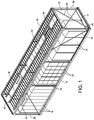
- FIG. 1 shows a platform 12 of a of a re-usable modular skid assembly, which is generally indicated at 10 in FIG. 4 , that has been installed on site, without power cables and other cables shown.
- the platform 12 includes a plate 14 with an upper surface that supports electrical components, such as several battery cabinets, each indicated at 16, several battery breaker control boxes, each indicated at 18, several uninterruptible power supply (UPS) cabinets, each indicated at 20, several input switchgear cabinets, each indicated at 22, and several output switchgear cabinets 24.
- UPS uninterruptible power supply
- Each post 26 extends vertically from the platform 12 to support a cable ladder support 28 positioned above the platform 12 and above the electrical components.
- Cable ladders each indicated at 30, are secured to the cable ladder support 28, and are useful to guide cables from an external power supply or other external electrical components to the electrical components that are supported on the platform.
- Shipping straps 32 are each secured at a first (lower) end to the platform 12 and at a second (upper) end to the cable ladder support 28. The shipping straps 32 improve stability of the platform 12 and cable ladder support 28 during hoisting, positioning, and transporting of the platform 12. Additional shipping straps can be provided to further stabilize the platform 12.
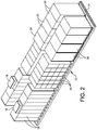
- FIG. 2 shows the platform 12 of the modular skid assembly 10 and the electrical components without the posts 26, cable ladder support 28, and cable ladders 30 secured to the platform 12.
- the electrical components are secured to the upper surface of the plate 14 of the platform 12.
- each electrical component is secured by fasteners to the plate 14 so the respective electrical components are secured to the platform 12 during hoisting, positioning, and transporting of the platform 12 and electrical components.
- FIGS. 3-7 show the embodiment of the modular skid assembly 10 of FIGS. 1 and 2 of the present disclosure in further detail.
- the modular skid assembly 10 is configured to transport and support at least one modular electrical component, and includes at least one stabilizing structure that is releasably securable to a platform 12.
- FIG. 3 shows the platform 12 of the modular skid assembly 10 before electrical components have been secured to the platform 12.
- the plate 14 of the platform 12 includes an upper surface configured to support the modular electrical components (e.g., components 16, 18, 20, 22 and 24).
- the plate 14 is supported on its sides by two side beams 40A, 40B and several joists 42 extending crosswise beneath the plate 14.
- a first side beam e.g., side beam 40A
- the first side beam 40A is secured to the plate 14 by a suitable method, which will be described below.
- a second side beam e.g., side beam 40B
- the second side beam 40B is secured to the plate 14.
- the joists 42 extend laterally beneath the plate 14, and extend between the first side beam 40A and the second side beam 40B.
- FIG. 4 shows the platform 12 with a first shipping beam 48A and a second shipping beam 48B secured to the platform 12.
- the first shipping beam 48A is releasably secured to the first side beam 40A of the platform 12.
- the second shipping beam 48B is releasably secured to the second side beam 40B of the platform 12.
- the first side beam 40A is a C-channel beam
- the second side beam 40B is a C-channel beam
- the first shipping beam 48A is a C-channel beam
- the second shipping beam 48B is a C-channel beam.
- a web of the first shipping beam 48A is positioned adjacent to a web of the first side beam 40A
- a web of the second shipping beam 48B is positioned adjacent to a web of the second side beam 40B.
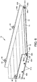
- FIGS. 5A and 5B show end views of FIG. 4 .
- FIGS. 5A and 5B show that when the first shipping beam 48A is secured to the first side beam 40A, a web 50A of the first side beam 40A is directly adjacent a web 52A of the first shipping beam 48A.
- a web 50B of the second side beam 40B is directly adjacent a web 52B of the second shipping beam 48B.
- the upper and lower flanges 53A, 53B of the first shipping beam 48A extend laterally in an opposite direction to the upper and lower flanges 55A, 55B of the first side beam 40A, and the upper and lower flanges 53C, 53D of the second shipping beam 48B extend laterally in an opposite direction to the upper and lower flanges 55C, 55D of the second side beam 40B.
- the first shipping beam 48A is releasably securable to the first side beam 40A by several first fasteners, each indicated at 54A, which are shown at spaced apart locations along the length of the first shipping beam 48A in FIG. 6 . Because the web 50A of the first side beam 40A is directly adjacent and fastened to the web 52A of the first shipping beam 48A, the first shipping beam 48A improves the stability of the first side beam 40A during hoisting, positioning, and transportation of the platform 12. A thickness 56A of the web 52A of the first shipping beam 48A and the flanges 53A of the first shipping beam 48A provide increased resistance to bending loads applied to the first side beam 40A due to the weight of electrical components on the upper surface of the plate 14.
- the thickness 56A of the web 52A of the first shipping beam 48A is greater than a thickness 58A of the web 50A of the first side beam 40A, and a height 60A of the first shipping beam 48A is greater than a height 62A of the first side beam 40A.
- the second shipping beam 48B is releasably securable to the second side beam 40B by several second fasteners, each indicated at 54B, at spaced apart locations along the length of the second shipping beam 48B. Because the web 50B of the second side beam 40B is directly adjacent and fastened to the web 52B of the second shipping beam 48B, the second shipping beam 48B improves the stability of the second side beam 40B during hoisting, positioning, and transportation of the platform 12. A thickness 56B of the web 52B of the second shipping beam 48B and the flanges 53B of the second shipping beam provide increased resistance to bending loads applied to the second side beam 40B due to the weight of electrical components on the upper surface of the plate 14.
- the thickness 56B of the web 52B of the second shipping beam 48B is greater than a thickness 58B of the web 50B of the second side beam 40B, and a height 60B of the second shipping beam 48B is greater than a height 62B of the second side beam 40B.
- the first side beam 40A is welded to one side, e.g., side 44, of the plate 14, and the second side beam 40B is welded to the opposite side, e.g., side 46, of the plate 14.
- Each of the joists 42 is welded to the first side beam 40A and to the second side beam 40B.
- Each of the joists 42 is also welded to the plate 14.
- a lower surface 70 of the plate 14 directly engages an upper surface 72A of the first side beam 40A, an upper surface 72B of the second side beam 40B, and an upper surface 74 of each joist 42.
- the weight of the platform 12 and the electrical components is supported on the support surface by a lower surface 76A of the first side beam 40A, a lower surface 76B of the second side beam 40B, and a lower surface 78 of each joist 42.
- a lower surface 80A of the first shipping beam 48A is flush with the lower surface 76A of the first side beam 40A and the respective lower surface 78 of each joist 42.
- a lower surface 80B of the second shipping beam 48B is flush with the lower surface 76B of the second side beam 40B and the respective lower surface 78 of each joist 42. Because of this geometry, when the modular skid assembly 10 is moved into position on site, the lower surface 80A of the first shipping beam 48A, the lower surface 80B of the second shipping beam 48B, the lower surface 76A of the first side beam 40A, the lower surface 76B of the second side beam 40B, and the respective lower surface 78 of each joist 42 each engages the support surface of the end-use site.
- the first shipping beam 48A can then be released from the first side beam 40A by removing the fasteners 54A
- the second shipping beam 48B can be released from the second side beam 40B by removing the fasteners 54B.
- each of the first fasteners 54A includes a bolt threadably secured to a nut
- each of the second fasteners 54B includes a bolt threadably secured to a nut.
- other types of fasteners can be used as the first fasteners 54A and the second fasteners 54B.
- the first shipping beam 48A and the second shipping beam 48B are each configured to be hoisted.
- the first shipping beam 48A further includes several lifting lugs, each indicated at 82, positioned along a length of the first shipping beam.
- the second shipping beam further includes several lifting lugs 82 positioned along a length of the second shipping beam.
- Each lifting lug 82 includes an aperture 83 configured to receive a hook to allow a user to hoist the modular skid by connecting the lifting lugs to a hoisting device, such as a crane.
- the first shipping beam 48A and the second shipping beam 48B are each configured to be secured to a vehicle during transportation of the modular skid assembly 10.
- the first shipping beam 48A includes several lashing members, each indicated at 84, and the second shipping beam 48B includes several lashing members that are similar to lashing members 84.
- Each lashing member 84 on the first shipping beam 48A is formed as an elongated member having a first end secured to the first shipping beam 48A and a second end secured to the first shipping beam 48A, so that a strap or hook can be secured to a middle portion of the elongated member 84.
- each lashing member which as mentioned above is similar or identical to lashing members 84, on the second shipping beam 48B is formed as an elongated member having a first end secured to the second shipping beam 48B and a second end secured to the second shipping beam 48B, so that a strap or hook can be secured to a middle portion of the lashing member.
- the lashing members 84 enable a user to tie down the modular skid assembly 10 to a flatbed surface on a truck to transport of the modular skid assembly.
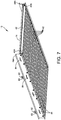
- FIG. 7 shows the plurality of joists 42 spaced apart longitudinally underneath the lower surface of the plate 14 of the platform.
- the plate 14 is 0.25 inch thick, and is made of steel.
- Each joist 42 is an I-beam that is 4 inches high and weighs 7.7 pounds per foot.
- the first side beam 40A is a C-channel beam that is 4 inches high and weighs 7.25 pounds per foot.
- the second side beam 40B is a C-channel beam that is 4 inches high and weighs 7.25 pounds per foot.
- the first shipping beam 48A is a Cchannel beam that is 10 inches high and weighs 25 pounds per foot.
- the second shipping beam 48B is a C-channel beam that is 10 inches high and weighs 25 pounds per foot. In other embodiments, other beams can be used in place of the shipping beams, depending on the weight of the electrical components.
- the platform of the modular skid assembly includes a plate having an upper surface configured to support the modular electrical component.
- the platform includes a first side beam, a second side beam, and several joists.
- the first side beam extends longitudinally along one side of the plate, and is secured to the plate.
- the second side beam extends longitudinally along an opposite side of the plate, and is secured to the plate.
- the joists extend laterally beneath the plate, and extend between the first side beam and the second side beam.
- a first stabilizing structure and a second stabilizing structure are each releasably securable to the platform.
- the first stabilizing structure is releasably secured to the first side beam
- the second stabilizing structure is releasably secured to the second side beam.
- the first stabilizing structure and the second stabilizing structure can be Cchannel beams, beams with square cross-sections, beams with L-shaped cross sections, beams with other cross-sections, or other stabilizing structure.
- each of the first stabilizing structure and the second stabilizing structure is a rail.
- the lower surface of the first stabilizing structure is flush with a lower surface of the first side beam
- a lower surface of the second stabilizing structure is flush with a lower surface of the second side beam
- first side beam and the second side beam are welded to the plate, and each of the joists is welded to the first side beam and the second side beam.
- first stabilizing structure is releasably securable to the first side beam by several fasteners
- second stabilizing structure is releasably securable to the second side beam via a second plurality of fasteners.
- first plurality of fasteners is a first plurality of bolts and the second plurality of fasteners is a second plurality of bolts.
- first stabilizing structure and the second stabilizing structure each further include at least one lifting lug. In some embodiments, the first stabilizing structure and the second stabilizing structure each further include one or more lashing members.
- At least one electrical component is bolted to the plate.
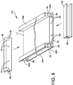
- FIG. 8 shows a partially exploded view of a skid assembly, generally indicated at 100, which includes all of the features of the modular skid assembly 10 of FIGS. 3-7 , and includes additional features.
- a gusset 86A is secured, for example by a weld, to a first end of the first shipping beam 48A, and a gusset 86A is secured, for example by a weld, to a second end of the first shipping beam 48A.
- Each gusset 86A is flush with the respective end of the first shipping beam 48A.
- a gusset 86B is secured, for example by a weld, to a first end of the second shipping beam 48B, and a gusset, similar to gusset 86B is secured, for example by a weld, to a second end of the second shipping beam 48B.
- Each gusset 86B is flush with the respective end of the second shipping beam 48B.
- a first end plate 88 is secured, for example by a weld, to a first end of the plate 14, and a second end plate, similar to end plate 88 is secured, for example by a weld, to a second end of the plate 14.
- a first end beam 90 is secured to the first end plate 88, and a second end beam 90 is secured to the second end plate.
- Each end beam 90 is secured to one of the gussets 86A on the first shipping beam 48A and is also secured to one of the gussets 86B on the second shipping beam 48B.
- a plurality of fasteners are provided, with each fastener extending through one of a plurality of apertures 92 on the respective end plate 88 and through one of a plurality of apertures 94 on the respective end beam 90.
- a plurality of fasteners is provided, with each fastener extending through one of a plurality of apertures extending through one of a plurality of apertures 96 on the respective gusset 86A, 86B and through one of a plurality of apertures 98 on the respective end beam 90.
- the end beams 90 improve the resistance of the skid assembly 100 to twisting.
- different beams or additional beams are used to tie the first side beam 40A and the second side beam 40B to prevent twisting.
- FIG. 9 shows a skid assembly 200, which includes all of the features of the modular skid assembly 10 of FIGS. 3-7 , and includes cleats formed on the shipping beams.
- FIG. 9 shows a portion of the first shipping beam 48A and a portion of the first side beam 40A.
- a cleat 102 is shown protruding from a longitudinal surface of the shipping beam 48A.
- the placement of the cleat 102 within the recess 104 is designed to reduce the shear stress on the first fasteners 54A that extend through apertures 106 on the first shipping beam 48A and through the apertures 108 on the first side beam 40A to connect the first shipping beam 48A to the first side beam 40A.
- a cleat can be formed on the second shipping beam 48B to engage a recess defined in the second side beam 40B when the second shipping beam is secured to the second side beam, wherein the engagement of the cleat with the recess is designed to reduce the shear stress on the set of second fasteners 54B that connect the second shipping beam 48B to the second side beam 40B.
- a plurality of cleats are formed on the first shipping beam 48A and a plurality of recesses are defined on the first side beam 40A. Each respective cleat of the plurality of cleats formed on the first shipping beam 48A is received in a respective recess of the plurality of recesses defined on the first side beam 40A.
- a plurality of cleats are formed on the second shipping beam 48B and a plurality of recesses are defined on the second side beam 40B. Each respective cleat of the plurality of cleats formed on the second shipping beam 48B is received in a respective recess of the plurality of recesses defined on the second side beam 40B.
- each cleat predominantly support the vertical load between the respective side beam and the respective shipping beam.
- each cleat is formed by a pin or plate that is welded to the respective shipping beam.
- At least some embodiments of the skid assembly of the present disclosure can be loaded on a truck and slid off of the truck onto an end-use site. Some embodiments include wheels to facilitate this.
- FIGS. 10A and 10B show a skid assembly 300, which includes all of the features of the modular skid assembly 10 of FIGS. 3-7 , and includes wheels.
- a partial view of the skid assembly 300 shows the first shipping beam 48A secured to the platform 12.
- the first side beam 40A and the plate 14 of the platform 12 are shown.
- a wheel support plate 110 is secured to the first shipping beam 48A, for example, by welding.
- a box 112 is secured to the wheel support plate 110.
- the box 112 includes an upper wall 114, a lower wall, 116, a first side wall 118 and a second side wall 120.
- a threaded shaft 122 extends through a threaded aperture in the upper wall 114 and an aperture in the lower wall.
- a caster 124 includes a wheel 126, which is pivotally secured to a lower end of the threaded shaft 122.
- the height of plate 14 with respect to a support surface on which the skid assembly 300 is positioned is adjustable by engaging a wrench with an upper end 128 of the threaded shaft 122 to rotate the threaded shaft with respect to the upper wall 114.
- an alternative wheel height adjustment mechanism is provided to allow a user to adjust the height of the platform with respect to a support surface on which the skid assembly is supported by the wheels.
- each wheel secured to a respective one of four corners of the assembly, and each wheel being vertically adjustable with respect to the plate 14.
- two wheels are supported at opposite ends of the first shipping beam 48A and two wheels are supported at opposite ends of the second shipping beam 48B.
- each respective threaded shaft 122 is rotated to an orientation such that there is a clearance 130 between the lower surface of the first shipping beam 48A and the lower edge of the wheels supported on the first shipping beam 48A, and such that there is a clearance between the lower surface of the second shipping beam 48B and the lower edge of the wheels supported on the second shipping beam, a user may roll the skid assembly 300 along the support surface.
- each threaded shaft 122 may be rotated to lower the platform 12 onto the support surface.
- the plurality of first fasteners 54A securing the first shipping beam 48A to the first side beam 40A may be removed and the plurality of second fasteners 54B securing the second shipping beam 48B to the second side beam 40B may be removed.
- a number of wheels other than four are provided.
- FIG. 11 shows a modular skid assembly 400 including the platform 12 of FIG. 3 with a first shipping plate 210A and a second shipping plate 210B secured to the platform 12.
- the first shipping plate 210A is releasably secured to the first side beam 40A of the platform 12.
- the second shipping plate 210B is releasably secured to the second side beam 40B of the platform 12.
- the first side beam 40A is a C-channel beam
- the second side beam 40B is a C-channel beam.
- the first shipping plate 210A is a heavy plate having a constant thickness (or at least a substantially constant thickness)
- the second shipping plate 210B is a heavy plate having a constant thickness (or at least a substantially constant thickness).
- FIG. 11 shows that when the first shipping plate 210A is secured to the first side beam 40A, a web 50A of the first side beam 40A is directly adjacent a longitudinal surface 212A of the first shipping plate 210A. Similarly, when the second shipping plate 210B is secured to the second side beam 40B, a web 50B of the second side beam 40B is directly adjacent a longitudinal surface 212B of the second shipping plate 210B.
- a plurality of fasteners each indicated at 214, secure the first shipping plate 210A to the first side beam 40A. Similarly, a plurality of fasteners secure the second shipping plate 210B to the second side beam 40B.
- the height of the shipping plate 210A provides improved bending strength to the skid assembly 400.
- the height of the second shipping plate 210B provides improved bending strength to the skid assembly 400.
- the first shipping plate 210A improves the stability of the first side beam 40A during hoisting, positioning, and transportation of the platform 12.
- a thickness 216A of the first shipping plate 210A and a height 218A of the first shipping plate provide increased resistance to bending loads applied to the first side beam 40A due to the weight of electrical components on the upper surface of the plate 14.
- the thickness 216A of the first shipping plate 210A is greater than a thickness 58A of the web 50A of the first side beam 40A, and a height 218A of the first shipping plate 210A is greater than a height 62A of the first side beam 40A.
- the second shipping plate 210B is releasably securable to the second side beam 40B by several second fasteners, not shown, which are at spaced apart locations along the length of the second shipping plate 210B. Because the web 50B of the second side beam 40B is directly adjacent and fastened to the longitudinal surface 212B of the second shipping plate 210B, the second shipping plate 210B improves the stability of the second side beam 40B during hoisting, positioning, and transportation of the platform 12. A thickness 216B of the second shipping plate 210B and a height 218B of the second shipping plate provide increased resistance to bending loads applied to the second side beam 40B due to the weight of electrical components on the upper surface of the plate 14.
- the thickness 216B of the second shipping plate 210B is greater than a thickness 58B of the web 50B of the second side beam 40B, and a height 218B of the second shipping plate 210B is greater than a height 62B of the second side beam 40B.
- a lower surface 220A of the first shipping plate 210A is flush with the lower surface 76A of the first side beam 40A and the respective lower surface 78 of each joist 42.
- a lower surface 220B of the second shipping plate 210B is flush with the lower surface 76B of the second side beam 40B and the respective lower surface 78 of each joist 42.
- the lower surface 220A of the first shipping plate 210A, the lower surface 220B of the second shipping plate 210B, the lower surface 76A of the first side beam 40A, the lower surface 76B of the second side beam 40B, and the respective lower surface 78 of each joist 42 each engages the support surface of the end-use site.
- the first shipping plate 210A then can be released from the first side beam 40A by removing the fasteners 214, and the second shipping plate 210B can be released from the second side beam 40B by removing the respective fasteners.
- each of the fasteners 214 includes a bolt threadably secured to a nut.
- other types of fasteners can be used as fasteners 214.
- the first shipping plate 210A and the second shipping plate 210B are configured for shipping and lifting heavy loads.
- Lift nodes 222 are provided along the length of the first shipping plate 210A, for example near upper ends of the second shipping plate and at the middle of the upper edge of the shipping plate 210A, as shown in FIG. 11 .
- Lift nodes 222 are provided along the length of the second shipping plate 210B, for example near ends of the second shipping plate and at the middle of the upper edge of the shipping plate 210B, as shown in FIG. 11 .
- FIG. 12 shows an exemplary embodiment of a method, generally indicated at 1000, according to the present disclosure.
- a modular skid assembly is provided.
- the modular skid assembly is configured to transport one or more modular electrical components, and, in one embodiment, embodies the modular skid assembly 10 or the modular skid assemblies 100, 200, 300, and 400 described herein.
- At least one modular electrical component is secured to the plate of the modular skid assembly.
- a first shipping beam is secured to the first side beam, and the second shipping beam is secured to the second side beam.
- another stabilizing means such as a first shipping plate is used in place of the first shipping beam.
- another stabilizing means such as a second shipping plate is used in place of the second shipping beam.
- a lifting device is secured to a first lifting lug associated with the first shipping beam and the lifting device is secured to a second lifting lug associated with the second shipping beam.
- the lifting device may be a crane, a hoist, or another lifting device.
- the modular skid assembly is positioned at a site where the electrical component or the electrical components will be used.
- the first shipping beam is removed from the first side beam, and the second shipping beam is removed from the second side beam.
- the first shipping beam and the second shipping beam can be reused.
- the first shipping beam and the second shipping beam can be secured to a second platform to hoist, position, and transport the second platform to a second site.
- the one or more modular electrical components are left secured to the platform.
- the modular electrical component is unsecured from the plate of the platform.
- the electrical component is unsecured from the platform, for example, when the electrical component is replaced.
- the present disclosure provides a modular skid assembly with a reduced cost, weight and height compared to previous pre-fabricated modules.
- the height H ( FIG. 3 ) of the platform 12 of modular skid assembly 10 is 4.25 inches above the support surface in the exemplary embodiment. This is favorable when the plate is used to mount switchgear, to prevent the operation handle of circuit breakers from exceeding the allowable height in some operational codes.
- the weight of a skid is an issue with shipping, availability of cranes, and foundation or floor loading.
- the reduced weight of the modular skid assembly 10 of the present disclosure improves the flexibility and speed at which platforms supporting electrical components can be installed.
- the modular skid assembly 10 allows increased flexibility in installation location options and allows the modular skid assembly 10 to be supported on an existing floor at a site or on a new floor at a site.
- the modular skid assembly 10 of the present disclosure can reduce the cost of electrical component installation projects by roughly 5%-7% by reusing structural elements of the module. Because the stabilizing structure provides increased strength to the platform for shipping, the platform includes less steel than previous skids. The present disclosure provides a modular skid assembly 10 with a reduced structural steel cost of approximately 50% compared to previous skids.
- the present disclosure provides a skid with a lower installed height, eliminating the need for extra platforms, railings and stairs. This also improves the safety of the installed equipment.
- the re-useable skid includes axles and wheels supported on the axles, so that the re-usable skid is formed as a trailer unit that is configured to be pulled by a truck.
- the wheels and axles may be removed first, then the modular unit is positioned on the site, and finally the shipping beams are removed.
- the entire modular skid is constructed on a trailer in a factory.
- the trailer is pulled by a truck to the installation site for the electrical components mounted on the modular skid.
- the modular skid is rolled off the tilting trailer into the final position at the installation site. This eliminates the need for cranes and other structures to support hoisting the modular skid.
- the modular skid assembly of the present disclosure can be provided to a user as a platform and at least one stabilizing structure (for example, at least one shipping beam).
- the modular skid assembly can be provided as a plurality of platforms and at least one stabilizing structure that is configured to be reused with multiple platforms.
- at least one platform configured to be secured to at least one stabilizing structure can be provided to a user independently of the stabilizing structure. This is beneficial where a user already has a stabilizing structure according to the present disclosure that can be releasably secured to the platform to hoist, position, and transport the at least one platform.
- a platform of the modular skid assembly of the present disclosure can be provided to a user with or without the electrical components secured to the platform.
- the shipping beams or shipping plates have respective lower surfaces that extend substantially below the lower surface of the platform (for example, 2 feet or 3 feet, or a distance between 2 feet and 3 feet) creating and elevated skid under which a user could run cables and bus way to interconnect the electrical equipment on the skid.
- the skid When the skid is placed on site, it could drop onto piers, columns or a structure that is part of the site development to maintain the elevated space after the shipping beams or shipping plates are removed. This would allow for under-the-platform interconnection and site wiring to and from the skid.
- Embodiments are not limited in their application to the details of construction and the arrangement of components set forth in the following description or illustrated in the drawings. Also, the phraseology and terminology used herein is for the purpose of description and should not be regarded as limiting. The use of "including,” “comprising,” or “having,” “containing,” “involving,” and variations thereof herein, is meant to encompass the items listed thereafter and equivalents thereof as well as additional items.
Landscapes
- Engineering & Computer Science (AREA)
- Mechanical Engineering (AREA)
- Microelectronics & Electronic Packaging (AREA)
- Power Engineering (AREA)
- Computer Hardware Design (AREA)
- General Engineering & Computer Science (AREA)
- Pallets (AREA)
- Handcart (AREA)
- Heat Treatments In General, Especially Conveying And Cooling (AREA)
- Bridges Or Land Bridges (AREA)
Abstract
Description
- The present disclosure is directed to a modular skid assembly for pre-fabricated (pre-fab) data center modules that include electrical components arranged on a platform and are shipped to an end-use site.
- Pre-fabricated data center modules typically require a platform or enclosure on which to mount electrical components. This platform should have sufficient strength and rigidity to withstand the loads and forces during hoisting, positioning, and transporting the module. Existing power module skid designs use a significant amount of welded structural steel to support the weight of electrical components supported by the power module skid. Much of the structure is needed only when hoisting and transporting the skid. Once the unit is placed into position on a floor or pad at the site, the heavy platform structure is typically no longer required as there is a foundation or pad to support the load. The platform is then used to anchor the electrical components.
- In prior skids, there are several thousand extra pounds of steel to purchase, fabricate, hoist, ship and install. In addition, the base of the prior skids has a height that provides the strength required for hoisting, positioning, and transporting, which makes access to the electrical components on the skid more difficult and sometimes requires extra platforms, railings or steps for accessibility or to meet code-mandated heights for actuator access.
- One aspect of the present disclosure is directed to a modular skid assembly that is configured to transport a modular electrical component. In some embodiments, the modular skid assembly comprises a plate including an upper surface configured to support the modular electrical component. A first side beam extends longitudinally along one side of the plate. The first side beam is secured to the plate. A second side beam extends longitudinally along an opposite side of the plate. The second side beam is secured to the plate. A plurality of joists extend laterally beneath the plate. The plurality of joists extend between the first side beam and the second side beam. A first shipping beam is configured to be releasably secured to the first side beam. A second shipping beam is configured to be releasably secured to the second side beam.
- In some embodiments, each of the first side beam and the second side beam includes a C-channel beam, and each of the first shipping beam and the second shipping beam includes a C-channel beam. The first shipping beam is positioned adjacent to the first side beam and the second shipping beam is positioned adjacent to the second side beam.
- In some embodiments, a lower flange of the first shipping beam extends laterally in an opposite direction to a lower flange of the first side beam, and a lower flange of the second shipping beam extends laterally in an opposite direction to a lower flange of the second side beam.
- In some embodiments, a lower surface of the lower flange of the first shipping beam is flush with the lower flange of the first side beam, and a lower surface of the lower flange of the second shipping beam is flush with the lower flange of the second side beam.
- In some embodiments, each of the first and second side beams is welded to the plate, and each of the plurality of joists is welded to the first side beam and the second side beam.
- In some embodiments, the first shipping beam is releasably securable to the first side beam via a first plurality of first fasteners, and the second shipping beam is releasably securable to the second side beam via a second plurality of second fasteners.
- In some embodiments, the at least one electrical component is bolted to the plate.
- In some embodiments, the first shipping beam and the second shipping beam each further include at least one lifting lug.
- In some embodiments, the first shipping beam and the second shipping beam each further include lashing members.
- In some embodiments, the modular skid assembly further comprises a first end beam and a second end beam. The first end beam is secured to a first gusset that is secured to a first end of the first shipping beam, and the first end beam is secured to a second gusset that is secured to a first end of the second shipping beam. The second end beam is secured to a third gusset that is secured to a second end of the first shipping beam. The second end beam is secured to a fourth gusset that is secured to a second end of the second shipping beam. Each end beam is secured to a respective end plate that is secured to a respective end of the plate.
- In some embodiments, a first cleat is formed on the first shipping beam and is configured to engage a first recess defined in the first side beam when the first shipping beam is secured to the first side beam, and a second cleat is formed on the second shipping beam and is configured to engage a second recess defined in the second side beam when the second shipping beam is secured to the second side beam.
- In some embodiments, the modular skid assembly further comprises four wheels, each wheel secured to a respective one of four corners of the assembly. Each wheel is vertically adjustable with respect to the plate.
- In some embodiments, a modular skid assembly is configured to transport a modular electrical component, and the modular skid assembly comprises a plate including an upper surface configured to support the modular electrical component; a first side beam extending longitudinally along one side of the plate, the first side beam being secured to the plate; a second side beam extending longitudinally along an opposite side of the plate, the second side beam being secured to the plate; a plurality of joists extending laterally beneath the plate, the plurality of joists extending between the first side beam and the second side beam; a first stabilizing means configured to be releasably secured to the first side beam; and a second stabilizing means configured to be releasably secured to the second side beam.
- In some embodiments, a lower surface of the first stabilizing means is flush with a lower surface of the first side beam, and a lower surface of the second stabilizing means is flush with a lower surface of the second side beam.
- In some embodiments, the first and second side beams are welded to the plate, and the plurality of joists are welded to the first side beam and the second side beam.
- In some embodiments, the first stabilizing means is releasably securable to the first side beam via a first plurality of fasteners, and the second stabilizing means is releasably securable to the second side beam via a second plurality of fasteners.
- In some embodiments, the at least one electrical component is bolted to the plate.
- In some embodiments, the first stabilizing means and the second stabilizing means each further include at least one lifting lug.
- In some embodiments, the first stabilizing means and the second stabilizing means each further include lashing members.
- In some embodiments, the first stabilizing means is a first shipping plate and the second stabilizing means is a second shipping plate.
- Another aspect of the present disclosure is directed to a method of transporting a modular component. In some embodiments, the method comprises providing a modular skid assembly configured to transport a modular electrical component, the modular skid assembly comprising a plate including an upper surface configured to support the modular electrical component, a first side beam extending longitudinally along one side of the plate, the first side beam being secured to the plate, a second side beam extending longitudinally along an opposite side of the plate, the second side beam being secured to the plate, a plurality of joists extending laterally beneath the plate, the plurality of joists extending between the first side beam and the second side beam, a first shipping beam configured to be releasably secured to the first side beam, and a second shipping beam configured to be releasably secured to the second side beam. In some embodiments, the method further includes securing a modular electrical component to the plate of the modular skid assembly, securing the first shipping beam to the first side beam, and securing the second shipping beam to the second side beam.
- In some embodiments, a lifting device is secured to a first lifting lug associated with the first shipping beam and to a second lifting lug associated with the second shipping beam.
- In some embodiments, the method includes removing the second shipping beam from the second side beam, removing the first shipping beam from the first side beam.
- In some embodiments, the method includes unsecuring the modular electrical component from the plate.
- The accompanying drawings are not intended to be drawn to scale. In the drawings, each identical or nearly identical component that is illustrated in various figures is represented by a like numeral. For purposes of clarity, not every component may be labeled in every drawing. In the drawings:
-
FIG. 1 is a perspective view of a platform that has been installed on site, without power cables and other cables shown; -
FIG. 2 is a perspective view thereof, without cable ladders and other components shown; -
FIG. 3 is a perspective view of a platform of an embodiment of a modular skid assembly; -
FIG. 4 is a perspective view of the embodiment of the platform shown inFIG. 3 , with shipping beams secured to the platform to form a first embodiment of a skid assembly; -
FIG. 5A is an end view of the platform ofFIG. 4 showing a first side; -
FIG. 5B is an end view of the platform ofFIG. 4 showing a second side; -
FIG. 6 is a perspective sectional view of the platform ofFIG. 4 ; -
FIG. 7 is a perspective sectional view of the platform ofFIG. 4 taken from a different perspective; -
FIG. 8 is a partially exploded view of another embodiment of a skid assembly; -
FIG. 9 is a partially exploded view of a portion of another embodiment of a skid assembly; -
FIG. 10A is a partial front view of another embodiment of a skid assembly; -
FIG. 10B is a partial side view of another embodiment of a skid assembly; -
FIG. 11 is a perspective view of another embodiment of a skid assembly; and -
FIG. 12 is a flowchart of a method of using an embodiment of the modular skid assembly. - The present disclosure relates generally to a skid for supporting electrical components both during shipping of the electrical components and during use of the electrical components at the site of the end user. Specifically, embodiments of the present disclosure are described below with reference to a modular skid assembly that has a platform to support electrical components during use by the end user and at least one stabilizing structure to support the platform during hoisting, positioning, and transporting of the platform.
- The modular skid assembly of the present disclosure can be partially disassembled after hoisting and transporting, and is more cost effective than previous skids.
- The present disclosure provides a modular skid assembly that is separated into multiple sections that are releasably fastened together during assembly and then disassembled after installation on site where the electrical components that are supported on a section of the skid are intended to be used. A first section of the modular skid assembly is the platform to which one or more pieces of pre-fabricated electrical components are mounted. This first section anchors the components and remains part of the product for the life of the installation of the platform and electrical components on site. A second section (or multiple second sections) of the modular skid assembly includes re-useable structural parts. The second section(s) attach to the platform and provide temporary strength and rigidity for hoisting, transporting and positioning of the platform. Once the assembly is positioned on site, the second section(s) are unfastened and disassembled from the platform and are returned for reuse on another project. Referring now to the drawings,
FIG. 1 shows aplatform 12 of a of a re-usable modular skid assembly, which is generally indicated at 10 inFIG. 4 , that has been installed on site, without power cables and other cables shown. In one exemplary configuration, theplatform 12 includes aplate 14 with an upper surface that supports electrical components, such as several battery cabinets, each indicated at 16, several battery breaker control boxes, each indicated at 18, several uninterruptible power supply (UPS) cabinets, each indicated at 20, several input switchgear cabinets, each indicated at 22, and severaloutput switchgear cabinets 24. Four posts, each indicated at 26, are included at corners of theplatform 12. Eachpost 26 extends vertically from theplatform 12 to support acable ladder support 28 positioned above theplatform 12 and above the electrical components. Cable ladders, each indicated at 30, are secured to thecable ladder support 28, and are useful to guide cables from an external power supply or other external electrical components to the electrical components that are supported on the platform. Shipping straps 32 are each secured at a first (lower) end to theplatform 12 and at a second (upper) end to thecable ladder support 28. The shipping straps 32 improve stability of theplatform 12 andcable ladder support 28 during hoisting, positioning, and transporting of theplatform 12. Additional shipping straps can be provided to further stabilize theplatform 12. -
FIG. 2 shows theplatform 12 of themodular skid assembly 10 and the electrical components without theposts 26,cable ladder support 28, andcable ladders 30 secured to theplatform 12. The electrical components are secured to the upper surface of theplate 14 of theplatform 12. For example, in some embodiments, each electrical component is secured by fasteners to theplate 14 so the respective electrical components are secured to theplatform 12 during hoisting, positioning, and transporting of theplatform 12 and electrical components. -
FIGS. 3-7 show the embodiment of themodular skid assembly 10 ofFIGS. 1 and2 of the present disclosure in further detail. Generally, themodular skid assembly 10 is configured to transport and support at least one modular electrical component, and includes at least one stabilizing structure that is releasably securable to aplatform 12.FIG. 3 shows theplatform 12 of themodular skid assembly 10 before electrical components have been secured to theplatform 12. Theplate 14 of theplatform 12 includes an upper surface configured to support the modular electrical components (e.g.,components platform 12 is installed on site, theplate 14 is supported on its sides by twoside beams several joists 42 extending crosswise beneath theplate 14. A first side beam, e.g.,side beam 40A, extends longitudinally along oneside 44 of theplate 14. Thefirst side beam 40A is secured to theplate 14 by a suitable method, which will be described below. A second side beam, e.g.,side beam 40B, extends longitudinally along anopposite side 46 of theplate 14. Thesecond side beam 40B is secured to theplate 14. Thejoists 42 extend laterally beneath theplate 14, and extend between thefirst side beam 40A and thesecond side beam 40B. -
FIG. 4 shows theplatform 12 with afirst shipping beam 48A and asecond shipping beam 48B secured to theplatform 12. Thefirst shipping beam 48A is releasably secured to thefirst side beam 40A of theplatform 12. Thesecond shipping beam 48B is releasably secured to thesecond side beam 40B of theplatform 12. In this embodiment of themodular skid assembly 10, thefirst side beam 40A is a C-channel beam, and thesecond side beam 40B is a C-channel beam. Thefirst shipping beam 48A is a C-channel beam, and thesecond shipping beam 48B is a C-channel beam. A web of thefirst shipping beam 48A is positioned adjacent to a web of thefirst side beam 40A, and a web of thesecond shipping beam 48B is positioned adjacent to a web of thesecond side beam 40B. -
FIGS. 5A and5B show end views ofFIG. 4 .FIGS. 5A and5B show that when thefirst shipping beam 48A is secured to thefirst side beam 40A, aweb 50A of thefirst side beam 40A is directly adjacent aweb 52A of thefirst shipping beam 48A. Similarly, when thesecond shipping beam 48B is secured to thesecond side beam 40B, aweb 50B of thesecond side beam 40B is directly adjacent aweb 52B of thesecond shipping beam 48B. - The upper and
lower flanges first shipping beam 48A extend laterally in an opposite direction to the upper andlower flanges first side beam 40A, and the upper andlower flanges second shipping beam 48B extend laterally in an opposite direction to the upper andlower flanges second side beam 40B. - The
first shipping beam 48A is releasably securable to thefirst side beam 40A by several first fasteners, each indicated at 54A, which are shown at spaced apart locations along the length of thefirst shipping beam 48A inFIG. 6 . Because theweb 50A of thefirst side beam 40A is directly adjacent and fastened to theweb 52A of thefirst shipping beam 48A, thefirst shipping beam 48A improves the stability of thefirst side beam 40A during hoisting, positioning, and transportation of theplatform 12. Athickness 56A of theweb 52A of thefirst shipping beam 48A and theflanges 53A of thefirst shipping beam 48A provide increased resistance to bending loads applied to thefirst side beam 40A due to the weight of electrical components on the upper surface of theplate 14. Thethickness 56A of theweb 52A of thefirst shipping beam 48A is greater than athickness 58A of theweb 50A of thefirst side beam 40A, and aheight 60A of thefirst shipping beam 48A is greater than aheight 62A of thefirst side beam 40A. - Similarly, the
second shipping beam 48B is releasably securable to thesecond side beam 40B by several second fasteners, each indicated at 54B, at spaced apart locations along the length of thesecond shipping beam 48B. Because theweb 50B of thesecond side beam 40B is directly adjacent and fastened to theweb 52B of thesecond shipping beam 48B, thesecond shipping beam 48B improves the stability of thesecond side beam 40B during hoisting, positioning, and transportation of theplatform 12. Athickness 56B of theweb 52B of thesecond shipping beam 48B and theflanges 53B of the second shipping beam provide increased resistance to bending loads applied to thesecond side beam 40B due to the weight of electrical components on the upper surface of theplate 14. Thethickness 56B of theweb 52B of thesecond shipping beam 48B is greater than athickness 58B of theweb 50B of thesecond side beam 40B, and aheight 60B of thesecond shipping beam 48B is greater than aheight 62B of thesecond side beam 40B. - In the embodiment of
FIGS. 3-7 , thefirst side beam 40A is welded to one side, e.g.,side 44, of theplate 14, and thesecond side beam 40B is welded to the opposite side, e.g.,side 46, of theplate 14. Each of thejoists 42 is welded to thefirst side beam 40A and to thesecond side beam 40B. Each of thejoists 42 is also welded to theplate 14. Alower surface 70 of theplate 14 directly engages anupper surface 72A of thefirst side beam 40A, anupper surface 72B of thesecond side beam 40B, and anupper surface 74 of eachjoist 42. The weight of theplatform 12 and the electrical components is supported on the support surface by alower surface 76A of thefirst side beam 40A, alower surface 76B of thesecond side beam 40B, and alower surface 78 of eachjoist 42. - A
lower surface 80A of thefirst shipping beam 48A is flush with thelower surface 76A of thefirst side beam 40A and the respectivelower surface 78 of eachjoist 42. Similarly, alower surface 80B of thesecond shipping beam 48B is flush with thelower surface 76B of thesecond side beam 40B and the respectivelower surface 78 of eachjoist 42. Because of this geometry, when themodular skid assembly 10 is moved into position on site, thelower surface 80A of thefirst shipping beam 48A, thelower surface 80B of thesecond shipping beam 48B, thelower surface 76A of thefirst side beam 40A, thelower surface 76B of thesecond side beam 40B, and the respectivelower surface 78 of eachjoist 42 each engages the support surface of the end-use site. Thefirst shipping beam 48A can then be released from thefirst side beam 40A by removing thefasteners 54A, and thesecond shipping beam 48B can be released from thesecond side beam 40B by removing thefasteners 54B. - In
FIG. 6 , each of thefirst fasteners 54A includes a bolt threadably secured to a nut, and each of thesecond fasteners 54B includes a bolt threadably secured to a nut. In other embodiments, other types of fasteners can be used as thefirst fasteners 54A and thesecond fasteners 54B. - The
first shipping beam 48A and thesecond shipping beam 48B are each configured to be hoisted. Thefirst shipping beam 48A further includes several lifting lugs, each indicated at 82, positioned along a length of the first shipping beam. The second shipping beam further includes several lifting lugs 82 positioned along a length of the second shipping beam. Each liftinglug 82 includes anaperture 83 configured to receive a hook to allow a user to hoist the modular skid by connecting the lifting lugs to a hoisting device, such as a crane. - The
first shipping beam 48A and thesecond shipping beam 48B are each configured to be secured to a vehicle during transportation of themodular skid assembly 10. Thefirst shipping beam 48A includes several lashing members, each indicated at 84, and thesecond shipping beam 48B includes several lashing members that are similar to lashingmembers 84. Each lashingmember 84 on thefirst shipping beam 48A is formed as an elongated member having a first end secured to thefirst shipping beam 48A and a second end secured to thefirst shipping beam 48A, so that a strap or hook can be secured to a middle portion of theelongated member 84. Similarly, each lashing member, which as mentioned above is similar or identical to lashingmembers 84, on thesecond shipping beam 48B is formed as an elongated member having a first end secured to thesecond shipping beam 48B and a second end secured to thesecond shipping beam 48B, so that a strap or hook can be secured to a middle portion of the lashing member. The lashingmembers 84 enable a user to tie down themodular skid assembly 10 to a flatbed surface on a truck to transport of the modular skid assembly. -
FIG. 7 shows the plurality ofjoists 42 spaced apart longitudinally underneath the lower surface of theplate 14 of the platform. - In the embodiment of
FIGS. 3-7 , theplate 14 is 0.25 inch thick, and is made of steel. Eachjoist 42 is an I-beam that is 4 inches high and weighs 7.7 pounds per foot. Thefirst side beam 40A is a C-channel beam that is 4 inches high and weighs 7.25 pounds per foot. Similarly, thesecond side beam 40B is a C-channel beam that is 4 inches high and weighs 7.25 pounds per foot. Thefirst shipping beam 48A is a Cchannel beam that is 10 inches high and weighs 25 pounds per foot. Thesecond shipping beam 48B is a C-channel beam that is 10 inches high and weighs 25 pounds per foot. In other embodiments, other beams can be used in place of the shipping beams, depending on the weight of the electrical components. - In another aspect of the present disclosure, a modular skid assembly configured to transport a modular electrical component includes a platform, a first stabilizing structure (a first stabilizing means), and a second stabilizing structure (a second stabilizing means). The platform of the modular skid assembly includes a plate having an upper surface configured to support the modular electrical component. The platform includes a first side beam, a second side beam, and several joists. The first side beam extends longitudinally along one side of the plate, and is secured to the plate. The second side beam extends longitudinally along an opposite side of the plate, and is secured to the plate. The joists extend laterally beneath the plate, and extend between the first side beam and the second side beam. A first stabilizing structure and a second stabilizing structure are each releasably securable to the platform. For example, in some embodiments, the first stabilizing structure is releasably secured to the first side beam, and the second stabilizing structure is releasably secured to the second side beam.
- The first stabilizing structure and the second stabilizing structure can be Cchannel beams, beams with square cross-sections, beams with L-shaped cross sections, beams with other cross-sections, or other stabilizing structure. In other embodiments, each of the first stabilizing structure and the second stabilizing structure is a rail.
- In some embodiments, the lower surface of the first stabilizing structure is flush with a lower surface of the first side beam, and a lower surface of the second stabilizing structure is flush with a lower surface of the second side beam.
- In some embodiments, the first side beam and the second side beam are welded to the plate, and each of the joists is welded to the first side beam and the second side beam. In some embodiments, the first stabilizing structure is releasably securable to the first side beam by several fasteners, and the second stabilizing structure is releasably securable to the second side beam via a second plurality of fasteners. In some embodiments, the first plurality of fasteners is a first plurality of bolts and the second plurality of fasteners is a second plurality of bolts.
- In some embodiments, the first stabilizing structure and the second stabilizing structure each further include at least one lifting lug. In some embodiments, the first stabilizing structure and the second stabilizing structure each further include one or more lashing members.
- In some embodiments, at least one electrical component is bolted to the plate.
-
FIG. 8 shows a partially exploded view of a skid assembly, generally indicated at 100, which includes all of the features of themodular skid assembly 10 ofFIGS. 3-7 , and includes additional features. Agusset 86A is secured, for example by a weld, to a first end of thefirst shipping beam 48A, and agusset 86A is secured, for example by a weld, to a second end of thefirst shipping beam 48A. Eachgusset 86A is flush with the respective end of thefirst shipping beam 48A. Similarly, a gusset 86B is secured, for example by a weld, to a first end of thesecond shipping beam 48B, and a gusset, similar to gusset 86B is secured, for example by a weld, to a second end of thesecond shipping beam 48B. Each gusset 86B is flush with the respective end of thesecond shipping beam 48B. Afirst end plate 88 is secured, for example by a weld, to a first end of theplate 14, and a second end plate, similar toend plate 88 is secured, for example by a weld, to a second end of theplate 14. Afirst end beam 90 is secured to thefirst end plate 88, and asecond end beam 90 is secured to the second end plate. Eachend beam 90 is secured to one of thegussets 86A on thefirst shipping beam 48A and is also secured to one of the gussets 86B on thesecond shipping beam 48B. To secure one of the end beams 90 to a respective one of theend plates 88, a plurality of fasteners are provided, with each fastener extending through one of a plurality ofapertures 92 on therespective end plate 88 and through one of a plurality ofapertures 94 on therespective end beam 90. To secure one of the end beams 90 to a respective one of thegussets 86A, 86B, a plurality of fasteners is provided, with each fastener extending through one of a plurality of apertures extending through one of a plurality ofapertures 96 on therespective gusset 86A, 86B and through one of a plurality ofapertures 98 on therespective end beam 90. - The end beams 90 improve the resistance of the
skid assembly 100 to twisting. In other embodiments, different beams or additional beams are used to tie thefirst side beam 40A and thesecond side beam 40B to prevent twisting. -
FIG. 9 shows askid assembly 200, which includes all of the features of themodular skid assembly 10 ofFIGS. 3-7 , and includes cleats formed on the shipping beams.FIG. 9 shows a portion of thefirst shipping beam 48A and a portion of thefirst side beam 40A. Acleat 102 is shown protruding from a longitudinal surface of theshipping beam 48A. When thefirst shipping beam 48A is secured to thefirst side beam 40A by thefirst fasteners 54A, thecleat 102 is received in arecess 104 defined on a longitudinal surface of thefirst side beam 40A. The placement of thecleat 102 within therecess 104 is designed to reduce the shear stress on thefirst fasteners 54A that extend throughapertures 106 on thefirst shipping beam 48A and through theapertures 108 on thefirst side beam 40A to connect thefirst shipping beam 48A to thefirst side beam 40A. Similarly, a cleat can be formed on thesecond shipping beam 48B to engage a recess defined in thesecond side beam 40B when the second shipping beam is secured to the second side beam, wherein the engagement of the cleat with the recess is designed to reduce the shear stress on the set ofsecond fasteners 54B that connect thesecond shipping beam 48B to thesecond side beam 40B. - In some embodiments, a plurality of cleats are formed on the
first shipping beam 48A and a plurality of recesses are defined on thefirst side beam 40A. Each respective cleat of the plurality of cleats formed on thefirst shipping beam 48A is received in a respective recess of the plurality of recesses defined on thefirst side beam 40A. Similarly, in some embodiments, a plurality of cleats are formed on thesecond shipping beam 48B and a plurality of recesses are defined on thesecond side beam 40B. Each respective cleat of the plurality of cleats formed on thesecond shipping beam 48B is received in a respective recess of the plurality of recesses defined on thesecond side beam 40B. - In some embodiments, the cleats predominantly support the vertical load between the respective side beam and the respective shipping beam. In some embodiments, each cleat is formed by a pin or plate that is welded to the respective shipping beam.
- At least some embodiments of the skid assembly of the present disclosure can be loaded on a truck and slid off of the truck onto an end-use site. Some embodiments include wheels to facilitate this.
-
FIGS. 10A and 10B show askid assembly 300, which includes all of the features of themodular skid assembly 10 ofFIGS. 3-7 , and includes wheels. - Referring to
FIG. 10A , a partial view of theskid assembly 300 shows thefirst shipping beam 48A secured to theplatform 12. Thefirst side beam 40A and theplate 14 of theplatform 12 are shown. Awheel support plate 110 is secured to thefirst shipping beam 48A, for example, by welding. - Referring to
FIG. 10B , abox 112 is secured to thewheel support plate 110. Thebox 112 includes anupper wall 114, a lower wall, 116, afirst side wall 118 and asecond side wall 120. A threadedshaft 122 extends through a threaded aperture in theupper wall 114 and an aperture in the lower wall. Acaster 124 includes awheel 126, which is pivotally secured to a lower end of the threadedshaft 122. The height ofplate 14 with respect to a support surface on which theskid assembly 300 is positioned is adjustable by engaging a wrench with anupper end 128 of the threadedshaft 122 to rotate the threaded shaft with respect to theupper wall 114. - In some embodiments, an alternative wheel height adjustment mechanism is provided to allow a user to adjust the height of the platform with respect to a support surface on which the skid assembly is supported by the wheels.
- In one embodiment, four wheels are provided, each wheel secured to a respective one of four corners of the assembly, and each wheel being vertically adjustable with respect to the
plate 14. For example, two wheels are supported at opposite ends of thefirst shipping beam 48A and two wheels are supported at opposite ends of thesecond shipping beam 48B. When each respective threadedshaft 122 is rotated to an orientation such that there is aclearance 130 between the lower surface of thefirst shipping beam 48A and the lower edge of the wheels supported on thefirst shipping beam 48A, and such that there is a clearance between the lower surface of thesecond shipping beam 48B and the lower edge of the wheels supported on the second shipping beam, a user may roll theskid assembly 300 along the support surface. After theplatform 12 has been moved to the desired position on the support surface, a user may rotate each threadedshaft 122 to lower theplatform 12 onto the support surface. Once theplatform 12 is directly resting on the support surface, the plurality offirst fasteners 54A securing thefirst shipping beam 48A to thefirst side beam 40A may be removed and the plurality ofsecond fasteners 54B securing thesecond shipping beam 48B to thesecond side beam 40B may be removed. - In some embodiments, a number of wheels other than four are provided.
-
FIG. 11 shows amodular skid assembly 400 including theplatform 12 ofFIG. 3 with afirst shipping plate 210A and asecond shipping plate 210B secured to theplatform 12. Thefirst shipping plate 210A is releasably secured to thefirst side beam 40A of theplatform 12. Thesecond shipping plate 210B is releasably secured to thesecond side beam 40B of theplatform 12. In this embodiment of themodular skid assembly 400, thefirst side beam 40A is a C-channel beam, and thesecond side beam 40B is a C-channel beam. Thefirst shipping plate 210A is a heavy plate having a constant thickness (or at least a substantially constant thickness), and thesecond shipping plate 210B is a heavy plate having a constant thickness (or at least a substantially constant thickness). -
FIG. 11 shows that when thefirst shipping plate 210A is secured to thefirst side beam 40A, aweb 50A of thefirst side beam 40A is directly adjacent alongitudinal surface 212A of thefirst shipping plate 210A. Similarly, when thesecond shipping plate 210B is secured to thesecond side beam 40B, aweb 50B of thesecond side beam 40B is directly adjacent alongitudinal surface 212B of thesecond shipping plate 210B. A plurality of fasteners, each indicated at 214, secure thefirst shipping plate 210A to thefirst side beam 40A. Similarly, a plurality of fasteners secure thesecond shipping plate 210B to thesecond side beam 40B. - The height of the
shipping plate 210A provides improved bending strength to theskid assembly 400. Similarly, the height of thesecond shipping plate 210B provides improved bending strength to theskid assembly 400. - Because the
web 50A of thefirst side beam 40A is directly adjacent and fastened to thelongitudinal surface 212A of thefirst shipping plate 210A, thefirst shipping plate 210A improves the stability of thefirst side beam 40A during hoisting, positioning, and transportation of theplatform 12. Athickness 216A of thefirst shipping plate 210A and aheight 218A of the first shipping plate provide increased resistance to bending loads applied to thefirst side beam 40A due to the weight of electrical components on the upper surface of theplate 14. Thethickness 216A of thefirst shipping plate 210A is greater than athickness 58A of theweb 50A of thefirst side beam 40A, and aheight 218A of thefirst shipping plate 210A is greater than aheight 62A of thefirst side beam 40A. - Similarly, the
second shipping plate 210B is releasably securable to thesecond side beam 40B by several second fasteners, not shown, which are at spaced apart locations along the length of thesecond shipping plate 210B. Because theweb 50B of thesecond side beam 40B is directly adjacent and fastened to thelongitudinal surface 212B of thesecond shipping plate 210B, thesecond shipping plate 210B improves the stability of thesecond side beam 40B during hoisting, positioning, and transportation of theplatform 12. Athickness 216B of thesecond shipping plate 210B and aheight 218B of the second shipping plate provide increased resistance to bending loads applied to thesecond side beam 40B due to the weight of electrical components on the upper surface of theplate 14. Thethickness 216B of thesecond shipping plate 210B is greater than athickness 58B of theweb 50B of thesecond side beam 40B, and aheight 218B of thesecond shipping plate 210B is greater than aheight 62B of thesecond side beam 40B. - A
lower surface 220A of thefirst shipping plate 210A is flush with thelower surface 76A of thefirst side beam 40A and the respectivelower surface 78 of eachjoist 42. Similarly, alower surface 220B of thesecond shipping plate 210B is flush with thelower surface 76B of thesecond side beam 40B and the respectivelower surface 78 of eachjoist 42. Because of this geometry, when themodular skid assembly 400 is moved into position on site, thelower surface 220A of thefirst shipping plate 210A, thelower surface 220B of thesecond shipping plate 210B, thelower surface 76A of thefirst side beam 40A, thelower surface 76B of thesecond side beam 40B, and the respectivelower surface 78 of eachjoist 42 each engages the support surface of the end-use site. Thefirst shipping plate 210A then can be released from thefirst side beam 40A by removing thefasteners 214, and thesecond shipping plate 210B can be released from thesecond side beam 40B by removing the respective fasteners. - In
FIG. 11 , each of thefasteners 214 includes a bolt threadably secured to a nut. In other embodiments, other types of fasteners can be used asfasteners 214. - The
first shipping plate 210A and thesecond shipping plate 210B are configured for shipping and lifting heavy loads. Liftnodes 222 are provided along the length of thefirst shipping plate 210A, for example near upper ends of the second shipping plate and at the middle of the upper edge of theshipping plate 210A, as shown inFIG. 11 . Liftnodes 222 are provided along the length of thesecond shipping plate 210B, for example near ends of the second shipping plate and at the middle of the upper edge of theshipping plate 210B, as shown inFIG. 11 . - Another aspect of the present disclosure provides a method of transporting a modular component or several modular components.
FIG. 12 shows an exemplary embodiment of a method, generally indicated at 1000, according to the present disclosure. Inblock 1110, a modular skid assembly is provided. The modular skid assembly is configured to transport one or more modular electrical components, and, in one embodiment, embodies themodular skid assembly 10 or themodular skid assemblies - In
block 1120, at least one modular electrical component is secured to the plate of the modular skid assembly. - In
block 1130, a first shipping beam is secured to the first side beam, and the second shipping beam is secured to the second side beam. In some embodiments, another stabilizing means, such as a first shipping plate is used in place of the first shipping beam. In some embodiments, another stabilizing means, such as a second shipping plate is used in place of the second shipping beam. - In
block 1140, a lifting device is secured to a first lifting lug associated with the first shipping beam and the lifting device is secured to a second lifting lug associated with the second shipping beam. The lifting device may be a crane, a hoist, or another lifting device. - In
block 1150, the modular skid assembly is positioned at a site where the electrical component or the electrical components will be used. - In
block 1160, the first shipping beam is removed from the first side beam, and the second shipping beam is removed from the second side beam. The first shipping beam and the second shipping beam can be reused. For example, the first shipping beam and the second shipping beam can be secured to a second platform to hoist, position, and transport the second platform to a second site. - Generally, the one or more modular electrical components are left secured to the platform. In
block 1170, the modular electrical component is unsecured from the plate of the platform. In some embodiments, the electrical component is unsecured from the platform, for example, when the electrical component is replaced. - The present disclosure provides a modular skid assembly with a reduced cost, weight and height compared to previous pre-fabricated modules. The height H (
FIG. 3 ) of theplatform 12 ofmodular skid assembly 10 is 4.25 inches above the support surface in the exemplary embodiment. This is favorable when the plate is used to mount switchgear, to prevent the operation handle of circuit breakers from exceeding the allowable height in some operational codes. - The weight of a skid is an issue with shipping, availability of cranes, and foundation or floor loading. The reduced weight of the
modular skid assembly 10 of the present disclosure improves the flexibility and speed at which platforms supporting electrical components can be installed. Themodular skid assembly 10 allows increased flexibility in installation location options and allows themodular skid assembly 10 to be supported on an existing floor at a site or on a new floor at a site. - The
modular skid assembly 10 of the present disclosure can reduce the cost of electrical component installation projects by roughly 5%-7% by reusing structural elements of the module. Because the stabilizing structure provides increased strength to the platform for shipping, the platform includes less steel than previous skids. The present disclosure provides amodular skid assembly 10 with a reduced structural steel cost of approximately 50% compared to previous skids. - The present disclosure provides a skid with a lower installed height, eliminating the need for extra platforms, railings and stairs. This also improves the safety of the installed equipment.
- In some embodiments, the re-useable skid includes axles and wheels supported on the axles, so that the re-usable skid is formed as a trailer unit that is configured to be pulled by a truck. Such embodiments reduce the weight of the modular unit when transported on the road. In such embodiments, the wheels and axles may be removed first, then the modular unit is positioned on the site, and finally the shipping beams are removed.
- In some embodiments, the entire modular skid is constructed on a trailer in a factory. The trailer is pulled by a truck to the installation site for the electrical components mounted on the modular skid. Then the modular skid is rolled off the tilting trailer into the final position at the installation site. This eliminates the need for cranes and other structures to support hoisting the modular skid.
- The modular skid assembly of the present disclosure can be provided to a user as a platform and at least one stabilizing structure (for example, at least one shipping beam). In other instances, the modular skid assembly can be provided as a plurality of platforms and at least one stabilizing structure that is configured to be reused with multiple platforms. In other instances, at least one platform configured to be secured to at least one stabilizing structure can be provided to a user independently of the stabilizing structure. This is beneficial where a user already has a stabilizing structure according to the present disclosure that can be releasably secured to the platform to hoist, position, and transport the at least one platform.
- A platform of the modular skid assembly of the present disclosure can be provided to a user with or without the electrical components secured to the platform.
- In some embodiments, the shipping beams or shipping plates have respective lower surfaces that extend substantially below the lower surface of the platform (for example, 2 feet or 3 feet, or a distance between 2 feet and 3 feet) creating and elevated skid under which a user could run cables and bus way to interconnect the electrical equipment on the skid. When the skid is placed on site, it could drop onto piers, columns or a structure that is part of the site development to maintain the elevated space after the shipping beams or shipping plates are removed. This would allow for under-the-platform interconnection and site wiring to and from the skid. This is an alternate approach to having a raised skid with underfloor cabling, whereby the raised platform is only temporary for manufacturing and shipping.
- Embodiments are not limited in their application to the details of construction and the arrangement of components set forth in the following description or illustrated in the drawings. Also, the phraseology and terminology used herein is for the purpose of description and should not be regarded as limiting. The use of "including," "comprising," or "having," "containing," "involving," and variations thereof herein, is meant to encompass the items listed thereafter and equivalents thereof as well as additional items.
- Having thus described several aspects of at least one embodiment, it is to be appreciated various alterations, modifications, and improvements will readily occur to those skilled in the art. Such alterations, modifications, and improvements are intended to be part of this disclosure, and are intended to be within the scope of the disclosure. Accordingly, the foregoing description and drawings are by way of example only.
Claims (15)
- A modular skid assembly configured to transport a modular electrical component, the modular skid assembly comprising:a plate including an upper surface configured to support the modular electrical component;a first side beam extending longitudinally along one side of the plate, the first side beam being secured to the plate;a second side beam extending longitudinally along an opposite side of the plate, the second side beam being secured to the plate; a plurality of joists extending laterally beneath the plate, the plurality of joists
extending between the first side beam and the second side beam;a first stabilizing means configured to be releasably secured to the first side beam; anda second stabilizing means configured to be releasably secured to the second side beam. - The modular skid assembly of claim 1 wherein the first stabilizing means include a first shipping beam and the second stabilizing means include a second shipping beam.
- The modular skid assembly of claim 2, wherein each of the first side beam and the second side beam includes a C-channel beam, and wherein each of the first shipping beam and the second shipping beam includes a C-channel beam, the first shipping beam being positioned adjacent to the first side beam and the second shipping beam being positioned adjacent to the second side beam.
- The modular skid assembly of claim 3, wherein a lower flange of the first shipping beam extends laterally in an opposite direction to a lower flange of the first side beam, and a lower flange of the second shipping beam extends laterally in an opposite direction to a lower flange of the second side beam.
- The modular skid assembly of claim 4, wherein a lower surface of the lower flange of the first shipping beam is flush with the lower flange of the first side beam, and a lower surface of the lower flange of the second shipping beam is flush with the lower flange of the second side beam.
- The modular skid assembly of any preceding claim, wherein each of the first and second side beams is welded to the plate, and each of the plurality of joists is welded to the first side beam and the second side beam.
- The modular skid assembly of any preceding claim, wherein the first stabilizing means includes a first shipping beam or a first shipping plate and is releasably securable to the first side beam via a first plurality of first fasteners, and the second stabilizing means includes a second shipping beam or a second shipping plate and is releasably securable to the second side beam via a second plurality of second fasteners.
- The modular skid assembly of any preceding claim, wherein the at least one electrical component is bolted to the plate.
- The modular skid assembly of any preceding claim, wherein the first stabilizing means and the second stabilizing means each further include at least one lifting lug or lashing members.
- The modular skid assembly of claim 2, further comprising a first end beam and a second end beam,
the first end beam being secured to a first gusset that is secured to a first end of the first shipping beam, and the first end beam secured to a second gusset that is secured to a first end of the second shipping beam, the second end beam secured to a third gusset that is secured to a second end of the first shipping beam, and the second end beam secured to a fourth gusset that is secured to a second end of the second shipping beam, and each end beam secured to a respective end plate that is secured to a respective end of the plate. - The modular skid assembly of claim 2, further comprising a first cleat formed on the first shipping beam and configured to engage a first recess defined in the first side beam when the first shipping beam is secured to the first side beam, and a second cleat formed on the second shipping beam and configured to engage a second recess defined in the second side beam when the second shipping beam is secured to the second side beam.
- The modular skid assembly of any preceding claim, further comprising four wheels, each wheel secured to a respective one of four corners of the assembly, each wheel being vertically adjustable with respect to the plate.
- A method of transporting a modular component, the method comprising:providing a modular skid assembly configured to transport a modular electrical component, the modular skid assembly comprising a plate including an upper surface configured to support the modular electrical component, a first side beam extending longitudinally along one side of the plate, the first side beam being secured to the plate, a second side beam extending longitudinally along an opposite side of the plate, the second side beam being secured to the plate, a plurality of joists extending laterally beneath the plate, the plurality of joists extending between the first side beam and the second side beam, a first shipping beam configured to be releasably secured to the first side beam, and a second shipping beam configured to be releasably secured to the second side beam;securing a modular electrical component to the plate of the modular skid assembly;securing the first shipping beam to the first side beam; andsecuring the second shipping beam to the second side beam.
- The method of claim 13, wherein a lifting device is secured to a first lifting lug associated with the first shipping beam and to a second lifting lug associated with the second shipping beam.
- The method of claim 13, further comprising removing the second shipping beam from the second side beam, removing the first shipping beam from the first side beam.
Priority Applications (1)
| Application Number | Priority Date | Filing Date | Title |
|---|---|---|---|
| EP22155134.4A EP4074624A3 (en) | 2017-09-07 | 2018-09-06 | Modular skid assemblies |
Applications Claiming Priority (1)
| Application Number | Priority Date | Filing Date | Title |
|---|---|---|---|
| US15/698,209 US10143105B1 (en) | 2017-09-07 | 2017-09-07 | Re-usable modular skid assembly for shipping electronic modules |
Related Child Applications (2)
| Application Number | Title | Priority Date | Filing Date |
|---|---|---|---|
| EP22155134.4A Division EP4074624A3 (en) | 2017-09-07 | 2018-09-06 | Modular skid assemblies |
| EP22155134.4A Previously-Filed-Application EP4074624A3 (en) | 2017-09-07 | 2018-09-06 | Modular skid assemblies |
Publications (2)
| Publication Number | Publication Date |
|---|---|
| EP3453643A1 true EP3453643A1 (en) | 2019-03-13 |
| EP3453643B1 EP3453643B1 (en) | 2022-03-09 |
Family
ID=63524130
Family Applications (2)
| Application Number | Title | Priority Date | Filing Date |
|---|---|---|---|
| EP18192914.2A Active EP3453643B1 (en) | 2017-09-07 | 2018-09-06 | Modular skid assembly and method of transporting an electrical module |
| EP22155134.4A Pending EP4074624A3 (en) | 2017-09-07 | 2018-09-06 | Modular skid assemblies |
Family Applications After (1)
| Application Number | Title | Priority Date | Filing Date |
|---|---|---|---|
| EP22155134.4A Pending EP4074624A3 (en) | 2017-09-07 | 2018-09-06 | Modular skid assemblies |
Country Status (3)
| Country | Link |
|---|---|
| US (1) | US10143105B1 (en) |
| EP (2) | EP3453643B1 (en) |
| CN (1) | CN109466901B (en) |
Cited By (1)
| Publication number | Priority date | Publication date | Assignee | Title |
|---|---|---|---|---|
| DE102022108702A1 (en) | 2022-04-11 | 2023-10-12 | Zeppelin Mobile Systeme Gmbh | Transport and operational framework |
Families Citing this family (3)
| Publication number | Priority date | Publication date | Assignee | Title |
|---|---|---|---|---|
| US11228166B1 (en) * | 2020-09-23 | 2022-01-18 | M.C. Dean Inc. | Free-standing cable tray support system and method of assembly |
| GB2618522B (en) * | 2022-04-25 | 2024-06-26 | Kes Group Inc Ltd | Portable data centre module |
| BR102022010903A2 (en) * | 2022-06-03 | 2023-12-19 | Scala Data Centers S.A. | DATA PROCESSING CENTER MODULE CONSISTING OF PREFABRICATED AND TRANSPORTABLE SEGMENTS, METHOD OF CONSTRUCTION OF DATA PROCESSING CENTER MODULE, DATA PROCESSING CENTER CONSTITUTED FROM SAID MODULE AND METHOD OF CONSTRUCTION OF SAID DATA PROCESSING CENTER |
Citations (4)
| Publication number | Priority date | Publication date | Assignee | Title |
|---|---|---|---|---|
| DE2822798A1 (en) * | 1978-05-24 | 1979-12-06 | B L Marine Consult Ab | Supporting component used between freight containers - has edge seals preventing liq. from flowing over |
| GB2369100A (en) * | 2000-11-17 | 2002-05-22 | Professional Handling Withcare | Transport skid |
| US20090146040A1 (en) * | 2007-12-07 | 2009-06-11 | Jeremy Small | Base/lifting structure |
| US20160105988A1 (en) * | 2009-05-29 | 2016-04-14 | Rosendin Electric, Inc. | Modular Power Skid Assembled with Different Electrical Cabinets and Components Mounted on the Skid |
Family Cites Families (15)
| Publication number | Priority date | Publication date | Assignee | Title |
|---|---|---|---|---|
| US2572348A (en) * | 1948-11-22 | 1951-10-23 | Lee D Johnson | Portable pallet mounting structure |
| US2933339A (en) * | 1953-06-30 | 1960-04-19 | Alvden Bror Robert Joh Hjalmar | Pallets and similar constructions for carrying heavy goods |
| WO2004013006A2 (en) * | 2002-08-06 | 2004-02-12 | Engineered Support Systems, Inc. | Aircraft and truck transportable pallet |
| DE102004057664B4 (en) * | 2004-11-29 | 2008-05-08 | Flexlift-Hubgeräte GmbH | Assembly platform for motor vehicles |
| CN101605437B (en) * | 2008-06-11 | 2012-03-07 | 深圳富泰宏精密工业有限公司 | Sliding cover structure |
| US9192069B2 (en) | 2013-08-05 | 2015-11-17 | Rosendin Electric, Inc. | Modular power skid assembled with different electrical cabinets and components mounted on the skid |
| US8681479B2 (en) | 2009-05-29 | 2014-03-25 | Rosendin Electric, Inc. | Various methods and apparatuses for an integrated power distribution platform |
| CN102616290B (en) * | 2011-01-27 | 2015-08-26 | 中集车辆(集团)有限公司 | Detachable skeleton car |
| US9337688B2 (en) | 2012-05-02 | 2016-05-10 | Modular Power Solutions, Inc. | Environmental system and modular power skid for a facility |
| US9219384B2 (en) | 2013-08-05 | 2015-12-22 | Rosendin Electric, Inc. | Modular power skid that can meet two or more different datacenter tier ratings |
| US9431798B2 (en) | 2014-09-17 | 2016-08-30 | Rosendin Electric, Inc. | Various methods and apparatuses for a low profile integrated power distribution platform |
| CN105730836A (en) * | 2014-12-10 | 2016-07-06 | 陕西子竹电子有限公司 | Frame of waste recycle case |
| US10093451B2 (en) * | 2015-09-03 | 2018-10-09 | R And D Enterprises Of Gulf Region Inc | Tank support base |
| US10499535B2 (en) | 2016-08-03 | 2019-12-03 | Schneider Electric It Corporation | Modular rack system |
| CN206318265U (en) * | 2016-12-29 | 2017-07-11 | 宁波旭力金属制品有限公司 | Cargo supports crossbeam fastens termination |
-
2017
- 2017-09-07 US US15/698,209 patent/US10143105B1/en active Active
-
2018
- 2018-09-06 EP EP18192914.2A patent/EP3453643B1/en active Active
- 2018-09-06 EP EP22155134.4A patent/EP4074624A3/en active Pending
- 2018-09-07 CN CN201811043999.2A patent/CN109466901B/en active Active
Patent Citations (4)
| Publication number | Priority date | Publication date | Assignee | Title |
|---|---|---|---|---|
| DE2822798A1 (en) * | 1978-05-24 | 1979-12-06 | B L Marine Consult Ab | Supporting component used between freight containers - has edge seals preventing liq. from flowing over |
| GB2369100A (en) * | 2000-11-17 | 2002-05-22 | Professional Handling Withcare | Transport skid |
| US20090146040A1 (en) * | 2007-12-07 | 2009-06-11 | Jeremy Small | Base/lifting structure |
| US20160105988A1 (en) * | 2009-05-29 | 2016-04-14 | Rosendin Electric, Inc. | Modular Power Skid Assembled with Different Electrical Cabinets and Components Mounted on the Skid |
Cited By (1)
| Publication number | Priority date | Publication date | Assignee | Title |
|---|---|---|---|---|
| DE102022108702A1 (en) | 2022-04-11 | 2023-10-12 | Zeppelin Mobile Systeme Gmbh | Transport and operational framework |
Also Published As
| Publication number | Publication date |
|---|---|
| EP4074624A2 (en) | 2022-10-19 |
| CN109466901B (en) | 2022-03-08 |
| CN109466901A (en) | 2019-03-15 |
| EP3453643B1 (en) | 2022-03-09 |
| EP4074624A3 (en) | 2022-12-28 |
| US10143105B1 (en) | 2018-11-27 |
Similar Documents
| Publication | Publication Date | Title |
|---|---|---|
| EP3453643B1 (en) | Modular skid assembly and method of transporting an electrical module | |
| US10863646B1 (en) | Modular data center support rack system and installation method | |
| US5575591A (en) | Apparatus and method for a modular support and lifting system | |
| US8167153B1 (en) | Hoist platform and scaffolding attachment means | |
| CN101479471A (en) | A handling system for a wind turbine nacelle, a method for vertical displacement of a wind turbine nacelle and a wind turbine nacelle | |
| CN110616891A (en) | Lift truck operated stacking template table system and method of operation thereof | |
| US10662658B2 (en) | Scaffold for supporting a working platform for bridges | |
| AU2021102347A4 (en) | Device for establishing a platform for landing goods | |
| CN1965136A (en) | Combined multi-layer channel platform and its construction method | |
| JPH08199580A (en) | Slope lifting device | |
| CA2920075C (en) | Scaffold | |
| EP4232393B1 (en) | Point-loaded lifting fork for lifting standing formwork | |
| CN115075210A (en) | Lifting beam structure of jacket | |
| CN211447765U (en) | Prefabricated superimposed sheet installation adjusting device | |
| KR101871834B1 (en) | Self-assembly foothold for construction | |
| JP6963995B2 (en) | Temporary passage and its construction method | |
| JP2011094456A (en) | Load bearing base, supporting material, and load bearing method | |
| CN111776957B (en) | Gantry crane with height-adjustable supporting legs and construction method thereof | |
| JP7645506B2 (en) | A sliding construction method for structures using a moving platform | |
| US3097713A (en) | Transportable scale with extensible deck | |
| WO2004097130A1 (en) | A transportable building and self-levelling chassis therefor | |
| JP3255772U (en) | Scaffolding base structure | |
| US20070264097A1 (en) | Systems and methods for loading and transporting freight and dunnage on railcars | |
| CN223645380U (en) | Walking board shipping protection tool for mining excavator | |
| US3489386A (en) | Reusable equipment emplacement rack assembly |
Legal Events
| Date | Code | Title | Description |
|---|---|---|---|
| PUAI | Public reference made under article 153(3) epc to a published international application that has entered the european phase |
Free format text: ORIGINAL CODE: 0009012 |
|
| STAA | Information on the status of an ep patent application or granted ep patent |
Free format text: STATUS: THE APPLICATION HAS BEEN PUBLISHED |
|
| AK | Designated contracting states |
Kind code of ref document: A1 Designated state(s): AL AT BE BG CH CY CZ DE DK EE ES FI FR GB GR HR HU IE IS IT LI LT LU LV MC MK MT NL NO PL PT RO RS SE SI SK SM TR |
|
| AX | Request for extension of the european patent |
Extension state: BA ME |
|
| STAA | Information on the status of an ep patent application or granted ep patent |
Free format text: STATUS: REQUEST FOR EXAMINATION WAS MADE |
|
| 17P | Request for examination filed |
Effective date: 20190913 |
|
| RBV | Designated contracting states (corrected) |
Designated state(s): AL AT BE BG CH CY CZ DE DK EE ES FI FR GB GR HR HU IE IS IT LI LT LU LV MC MK MT NL NO PL PT RO RS SE SI SK SM TR |
|
| STAA | Information on the status of an ep patent application or granted ep patent |
Free format text: STATUS: EXAMINATION IS IN PROGRESS |
|
| 17Q | First examination report despatched |
Effective date: 20200302 |
|
| GRAP | Despatch of communication of intention to grant a patent |
Free format text: ORIGINAL CODE: EPIDOSNIGR1 |
|
| STAA | Information on the status of an ep patent application or granted ep patent |
Free format text: STATUS: GRANT OF PATENT IS INTENDED |
|
| RIC1 | Information provided on ipc code assigned before grant |
Ipc: H05K 7/14 20060101ALI20210820BHEP Ipc: B65D 90/18 20060101ALI20210820BHEP Ipc: B65D 90/00 20060101ALI20210820BHEP Ipc: B65D 90/16 20060101AFI20210820BHEP |
|
| INTG | Intention to grant announced |
Effective date: 20210928 |
|
| GRAS | Grant fee paid |
Free format text: ORIGINAL CODE: EPIDOSNIGR3 |
|
| GRAA | (expected) grant |
Free format text: ORIGINAL CODE: 0009210 |
|
| STAA | Information on the status of an ep patent application or granted ep patent |
Free format text: STATUS: THE PATENT HAS BEEN GRANTED |
|
| AK | Designated contracting states |
Kind code of ref document: B1 Designated state(s): AL AT BE BG CH CY CZ DE DK EE ES FI FR GB GR HR HU IE IS IT LI LT LU LV MC MK MT NL NO PL PT RO RS SE SI SK SM TR |
|
| RAP3 | Party data changed (applicant data changed or rights of an application transferred) |
Owner name: SCHNEIDER ELECTRIC IT CORPORATION |
|
| REG | Reference to a national code |
Ref country code: CH Ref legal event code: EP Ref country code: AT Ref legal event code: REF Ref document number: 1473993 Country of ref document: AT Kind code of ref document: T Effective date: 20220315 |
|
| REG | Reference to a national code |
Ref country code: DE Ref legal event code: R096 Ref document number: 602018031877 Country of ref document: DE |
|
| REG | Reference to a national code |
Ref country code: IE Ref legal event code: FG4D |
|
| REG | Reference to a national code |
Ref country code: NL Ref legal event code: FP |
|
| REG | Reference to a national code |
Ref country code: LT Ref legal event code: MG9D |
|
| PG25 | Lapsed in a contracting state [announced via postgrant information from national office to epo] |
Ref country code: SE Free format text: LAPSE BECAUSE OF FAILURE TO SUBMIT A TRANSLATION OF THE DESCRIPTION OR TO PAY THE FEE WITHIN THE PRESCRIBED TIME-LIMIT Effective date: 20220309 Ref country code: RS Free format text: LAPSE BECAUSE OF FAILURE TO SUBMIT A TRANSLATION OF THE DESCRIPTION OR TO PAY THE FEE WITHIN THE PRESCRIBED TIME-LIMIT Effective date: 20220309 Ref country code: NO Free format text: LAPSE BECAUSE OF FAILURE TO SUBMIT A TRANSLATION OF THE DESCRIPTION OR TO PAY THE FEE WITHIN THE PRESCRIBED TIME-LIMIT Effective date: 20220609 Ref country code: LT Free format text: LAPSE BECAUSE OF FAILURE TO SUBMIT A TRANSLATION OF THE DESCRIPTION OR TO PAY THE FEE WITHIN THE PRESCRIBED TIME-LIMIT Effective date: 20220309 Ref country code: HR Free format text: LAPSE BECAUSE OF FAILURE TO SUBMIT A TRANSLATION OF THE DESCRIPTION OR TO PAY THE FEE WITHIN THE PRESCRIBED TIME-LIMIT Effective date: 20220309 Ref country code: BG Free format text: LAPSE BECAUSE OF FAILURE TO SUBMIT A TRANSLATION OF THE DESCRIPTION OR TO PAY THE FEE WITHIN THE PRESCRIBED TIME-LIMIT Effective date: 20220609 |
|
| REG | Reference to a national code |
Ref country code: AT Ref legal event code: MK05 Ref document number: 1473993 Country of ref document: AT Kind code of ref document: T Effective date: 20220309 |
|
| PG25 | Lapsed in a contracting state [announced via postgrant information from national office to epo] |
Ref country code: LV Free format text: LAPSE BECAUSE OF FAILURE TO SUBMIT A TRANSLATION OF THE DESCRIPTION OR TO PAY THE FEE WITHIN THE PRESCRIBED TIME-LIMIT Effective date: 20220309 Ref country code: GR Free format text: LAPSE BECAUSE OF FAILURE TO SUBMIT A TRANSLATION OF THE DESCRIPTION OR TO PAY THE FEE WITHIN THE PRESCRIBED TIME-LIMIT Effective date: 20220610 Ref country code: FI Free format text: LAPSE BECAUSE OF FAILURE TO SUBMIT A TRANSLATION OF THE DESCRIPTION OR TO PAY THE FEE WITHIN THE PRESCRIBED TIME-LIMIT Effective date: 20220309 |
|
| PG25 | Lapsed in a contracting state [announced via postgrant information from national office to epo] |
Ref country code: SM Free format text: LAPSE BECAUSE OF FAILURE TO SUBMIT A TRANSLATION OF THE DESCRIPTION OR TO PAY THE FEE WITHIN THE PRESCRIBED TIME-LIMIT Effective date: 20220309 Ref country code: SK Free format text: LAPSE BECAUSE OF FAILURE TO SUBMIT A TRANSLATION OF THE DESCRIPTION OR TO PAY THE FEE WITHIN THE PRESCRIBED TIME-LIMIT Effective date: 20220309 Ref country code: RO Free format text: LAPSE BECAUSE OF FAILURE TO SUBMIT A TRANSLATION OF THE DESCRIPTION OR TO PAY THE FEE WITHIN THE PRESCRIBED TIME-LIMIT Effective date: 20220309 Ref country code: PT Free format text: LAPSE BECAUSE OF FAILURE TO SUBMIT A TRANSLATION OF THE DESCRIPTION OR TO PAY THE FEE WITHIN THE PRESCRIBED TIME-LIMIT Effective date: 20220711 Ref country code: ES Free format text: LAPSE BECAUSE OF FAILURE TO SUBMIT A TRANSLATION OF THE DESCRIPTION OR TO PAY THE FEE WITHIN THE PRESCRIBED TIME-LIMIT Effective date: 20220309 Ref country code: EE Free format text: LAPSE BECAUSE OF FAILURE TO SUBMIT A TRANSLATION OF THE DESCRIPTION OR TO PAY THE FEE WITHIN THE PRESCRIBED TIME-LIMIT Effective date: 20220309 Ref country code: CZ Free format text: LAPSE BECAUSE OF FAILURE TO SUBMIT A TRANSLATION OF THE DESCRIPTION OR TO PAY THE FEE WITHIN THE PRESCRIBED TIME-LIMIT Effective date: 20220309 Ref country code: AT Free format text: LAPSE BECAUSE OF FAILURE TO SUBMIT A TRANSLATION OF THE DESCRIPTION OR TO PAY THE FEE WITHIN THE PRESCRIBED TIME-LIMIT Effective date: 20220309 |
|
| PG25 | Lapsed in a contracting state [announced via postgrant information from national office to epo] |
Ref country code: PL Free format text: LAPSE BECAUSE OF FAILURE TO SUBMIT A TRANSLATION OF THE DESCRIPTION OR TO PAY THE FEE WITHIN THE PRESCRIBED TIME-LIMIT Effective date: 20220309 Ref country code: IS Free format text: LAPSE BECAUSE OF FAILURE TO SUBMIT A TRANSLATION OF THE DESCRIPTION OR TO PAY THE FEE WITHIN THE PRESCRIBED TIME-LIMIT Effective date: 20220709 Ref country code: AL Free format text: LAPSE BECAUSE OF FAILURE TO SUBMIT A TRANSLATION OF THE DESCRIPTION OR TO PAY THE FEE WITHIN THE PRESCRIBED TIME-LIMIT Effective date: 20220309 |
|
| REG | Reference to a national code |
Ref country code: DE Ref legal event code: R097 Ref document number: 602018031877 Country of ref document: DE |
|
| PLBE | No opposition filed within time limit |
Free format text: ORIGINAL CODE: 0009261 |
|
| STAA | Information on the status of an ep patent application or granted ep patent |
Free format text: STATUS: NO OPPOSITION FILED WITHIN TIME LIMIT |
|
| PG25 | Lapsed in a contracting state [announced via postgrant information from national office to epo] |
Ref country code: DK Free format text: LAPSE BECAUSE OF FAILURE TO SUBMIT A TRANSLATION OF THE DESCRIPTION OR TO PAY THE FEE WITHIN THE PRESCRIBED TIME-LIMIT Effective date: 20220309 |
|
| 26N | No opposition filed |
Effective date: 20221212 |
|
| PG25 | Lapsed in a contracting state [announced via postgrant information from national office to epo] |
Ref country code: SI Free format text: LAPSE BECAUSE OF FAILURE TO SUBMIT A TRANSLATION OF THE DESCRIPTION OR TO PAY THE FEE WITHIN THE PRESCRIBED TIME-LIMIT Effective date: 20220309 |
|
| PG25 | Lapsed in a contracting state [announced via postgrant information from national office to epo] |
Ref country code: MC Free format text: LAPSE BECAUSE OF FAILURE TO SUBMIT A TRANSLATION OF THE DESCRIPTION OR TO PAY THE FEE WITHIN THE PRESCRIBED TIME-LIMIT Effective date: 20220309 |
|
| REG | Reference to a national code |
Ref country code: CH Ref legal event code: PL |
|
| REG | Reference to a national code |
Ref country code: BE Ref legal event code: MM Effective date: 20220930 |
|
| PG25 | Lapsed in a contracting state [announced via postgrant information from national office to epo] |
Ref country code: LU Free format text: LAPSE BECAUSE OF NON-PAYMENT OF DUE FEES Effective date: 20220906 |
|
| PG25 | Lapsed in a contracting state [announced via postgrant information from national office to epo] |
Ref country code: LI Free format text: LAPSE BECAUSE OF NON-PAYMENT OF DUE FEES Effective date: 20220930 Ref country code: IT Free format text: LAPSE BECAUSE OF FAILURE TO SUBMIT A TRANSLATION OF THE DESCRIPTION OR TO PAY THE FEE WITHIN THE PRESCRIBED TIME-LIMIT Effective date: 20220309 Ref country code: CH Free format text: LAPSE BECAUSE OF NON-PAYMENT OF DUE FEES Effective date: 20220930 |
|
| PG25 | Lapsed in a contracting state [announced via postgrant information from national office to epo] |
Ref country code: BE Free format text: LAPSE BECAUSE OF NON-PAYMENT OF DUE FEES Effective date: 20220930 |
|
| PG25 | Lapsed in a contracting state [announced via postgrant information from national office to epo] |
Ref country code: HU Free format text: LAPSE BECAUSE OF FAILURE TO SUBMIT A TRANSLATION OF THE DESCRIPTION OR TO PAY THE FEE WITHIN THE PRESCRIBED TIME-LIMIT; INVALID AB INITIO Effective date: 20180906 |
|
| PG25 | Lapsed in a contracting state [announced via postgrant information from national office to epo] |
Ref country code: CY Free format text: LAPSE BECAUSE OF FAILURE TO SUBMIT A TRANSLATION OF THE DESCRIPTION OR TO PAY THE FEE WITHIN THE PRESCRIBED TIME-LIMIT Effective date: 20220309 |
|
| PG25 | Lapsed in a contracting state [announced via postgrant information from national office to epo] |
Ref country code: MK Free format text: LAPSE BECAUSE OF FAILURE TO SUBMIT A TRANSLATION OF THE DESCRIPTION OR TO PAY THE FEE WITHIN THE PRESCRIBED TIME-LIMIT Effective date: 20220309 |
|
| PG25 | Lapsed in a contracting state [announced via postgrant information from national office to epo] |
Ref country code: TR Free format text: LAPSE BECAUSE OF FAILURE TO SUBMIT A TRANSLATION OF THE DESCRIPTION OR TO PAY THE FEE WITHIN THE PRESCRIBED TIME-LIMIT Effective date: 20220309 |
|
| PG25 | Lapsed in a contracting state [announced via postgrant information from national office to epo] |
Ref country code: MT Free format text: LAPSE BECAUSE OF FAILURE TO SUBMIT A TRANSLATION OF THE DESCRIPTION OR TO PAY THE FEE WITHIN THE PRESCRIBED TIME-LIMIT Effective date: 20220309 |
|
| PGFP | Annual fee paid to national office [announced via postgrant information from national office to epo] |
Ref country code: DE Payment date: 20250926 Year of fee payment: 8 |
|
| PGFP | Annual fee paid to national office [announced via postgrant information from national office to epo] |
Ref country code: NL Payment date: 20250925 Year of fee payment: 8 |
|
| PGFP | Annual fee paid to national office [announced via postgrant information from national office to epo] |
Ref country code: GB Payment date: 20250923 Year of fee payment: 8 |
|
| PGFP | Annual fee paid to national office [announced via postgrant information from national office to epo] |
Ref country code: FR Payment date: 20250925 Year of fee payment: 8 |
|
| PGFP | Annual fee paid to national office [announced via postgrant information from national office to epo] |
Ref country code: IE Payment date: 20250917 Year of fee payment: 8 |