EP3453609B1 - Active wing-twist mechanism and control system - Google Patents
Active wing-twist mechanism and control system Download PDFInfo
- Publication number
- EP3453609B1 EP3453609B1 EP18193804.4A EP18193804A EP3453609B1 EP 3453609 B1 EP3453609 B1 EP 3453609B1 EP 18193804 A EP18193804 A EP 18193804A EP 3453609 B1 EP3453609 B1 EP 3453609B1
- Authority
- EP
- European Patent Office
- Prior art keywords
- wing
- aircraft
- spar
- twist
- flexible wing
- Prior art date
- Legal status (The legal status is an assumption and is not a legal conclusion. Google has not performed a legal analysis and makes no representation as to the accuracy of the status listed.)
- Active
Links
Images



Classifications
-
- B—PERFORMING OPERATIONS; TRANSPORTING
- B64—AIRCRAFT; AVIATION; COSMONAUTICS
- B64C—AEROPLANES; HELICOPTERS
- B64C3/00—Wings
- B64C3/38—Adjustment of complete wings or parts thereof
- B64C3/52—Warping
-
- B—PERFORMING OPERATIONS; TRANSPORTING
- B64—AIRCRAFT; AVIATION; COSMONAUTICS
- B64C—AEROPLANES; HELICOPTERS
- B64C3/00—Wings
-
- B—PERFORMING OPERATIONS; TRANSPORTING
- B64—AIRCRAFT; AVIATION; COSMONAUTICS
- B64C—AEROPLANES; HELICOPTERS
- B64C3/00—Wings
- B64C3/38—Adjustment of complete wings or parts thereof
-
- B—PERFORMING OPERATIONS; TRANSPORTING
- B64—AIRCRAFT; AVIATION; COSMONAUTICS
- B64C—AEROPLANES; HELICOPTERS
- B64C39/00—Aircraft not otherwise provided for
- B64C39/10—All-wing aircraft
-
- B—PERFORMING OPERATIONS; TRANSPORTING
- B64—AIRCRAFT; AVIATION; COSMONAUTICS
- B64C—AEROPLANES; HELICOPTERS
- B64C9/00—Adjustable control surfaces or members, e.g. rudders
- B64C9/10—Adjustable control surfaces or members, e.g. rudders one surface adjusted by movement of another, e.g. servo tabs
-
- G—PHYSICS
- G05—CONTROLLING; REGULATING
- G05D—SYSTEMS FOR CONTROLLING OR REGULATING NON-ELECTRIC VARIABLES
- G05D1/00—Control of position, course, altitude or attitude of land, water, air or space vehicles, e.g. using automatic pilots
- G05D1/08—Control of attitude, i.e. control of roll, pitch, or yaw
- G05D1/0808—Control of attitude, i.e. control of roll, pitch, or yaw specially adapted for aircraft
- G05D1/0816—Control of attitude, i.e. control of roll, pitch, or yaw specially adapted for aircraft to ensure stability
-
- B—PERFORMING OPERATIONS; TRANSPORTING
- B64—AIRCRAFT; AVIATION; COSMONAUTICS
- B64C—AEROPLANES; HELICOPTERS
- B64C39/00—Aircraft not otherwise provided for
- B64C39/10—All-wing aircraft
- B64C2039/105—All-wing aircraft of blended wing body type
-
- Y—GENERAL TAGGING OF NEW TECHNOLOGICAL DEVELOPMENTS; GENERAL TAGGING OF CROSS-SECTIONAL TECHNOLOGIES SPANNING OVER SEVERAL SECTIONS OF THE IPC; TECHNICAL SUBJECTS COVERED BY FORMER USPC CROSS-REFERENCE ART COLLECTIONS [XRACs] AND DIGESTS
- Y02—TECHNOLOGIES OR APPLICATIONS FOR MITIGATION OR ADAPTATION AGAINST CLIMATE CHANGE
- Y02T—CLIMATE CHANGE MITIGATION TECHNOLOGIES RELATED TO TRANSPORTATION
- Y02T50/00—Aeronautics or air transport
- Y02T50/10—Drag reduction
Definitions
- the present disclosure relates to an aircraft having a flexible wing, an active wing-twist mechanism, and control system thereof.
- static wing tip twist is used to initiate stall at the wing root, leaving the control surfaces at the outer wing functional. This allows the pilot to recover using the outer wing control surfaces.
- a wing setup with static twist to mitigate stall can only be optimized for a narrow flight region.
- This situation is intensified with blended wing body (BWB) aircraft: to accommodate a payload the center-body airfoils may be thick. Thick airfoils stall at a higher angle of attack than thinner airfoils, assuming both are similar and well suited for the aircraft. This thickness discrepancy leads to the outer wings and the associated control surfaces stalling first. Stalled control surfaces are typically a non-recoverable event for a BWB.
- the twist amount is varied pursuant to the operating conditions, including those parameters used to determine the lift coefficient.
- the twist for reducing induced drag and/or improving lift may be employed by geometric or aerodynamic twist, including full span control surfaces used to provide roll control, high-lift and reduced induced drag.
- the twist may also be employed by twisting just a portion of the wing or the entire wing, either geometrically or aerodynamically.
- US2016/001874 describes active strut apparatus for use with aircraft and related methods.
- An example apparatus includes a first strut having a first end and a second end opposite the first end, the first end of the first strut is operatively coupled to a fuselage of an aircraft and the second end of the first strut is operatively coupled to a wing of the aircraft, and a first actuator is operatively coupled to the first strut to change an effective length of the first strut.
- the present disclosure relates to an active wing-twist mechanism and control system.
- One aspect of the disclosure involves an aircraft with an active wing-twist control system that includes a flexible wing defined by a wingspan, wherein the flexible wing comprises a first spar positioned in a fuselage of the aircraft and aligned in a span-wise direction, wherein a final wing tip rib is operatively coupled to the first spar; an actuation system to torsionally rotate the first spar about a twist axis, which, in turn, causes the final wing tip rib coupled to the first spar to rotate, thereby twisting at least a portion of the flexible wing; a sensor configured to measure a characteristic of the flexible wing; and a controller configured to command the actuation system to rotate the first spar based at least in part on input from the sensor.
- the flexible wing further comprises a second spar having a first end operatively coupled to the fuselage and a second end operatively coupled to the first spar, such that the second spar is configured to twist, rotate, revolve and/or pivot about the first spar.
- the second spar comprises an outer tube operatively coupled to a plurality of ribs, and the first spar is mounted concentrically within the second spar.
- Another aspect of the disclosure involves a method of controlling a wing-twist of an aircraft as described above, the method including the steps of: sensing a characteristic of the flexible wing; determining an appropriate wing-twist based at least in part on the sensed characteristic of the flexible wing; and rotating the first spar of the flexible wing based at least in part on the appropriate wing-twist determination, wherein the first spar and the final wing tip rib at least partly define a shape of the flexible wing, and wherein the shape of the flexible wing is altered by rotation of the first spar.
- "and/or” means any one or more of the items in the list joined by “and/or”.
- "x and/or y” means any element of the three-element set ⁇ (x), (y), (x, y) ⁇ . In other words, “x and/or y” means “one or both of x and y”.
- "x, y, and/or z” means any element of the seven-element set ⁇ (x), (y), (z), (x, y), (x, z), (y, z), (x, y, z) ⁇ . In other words, "x, y and/or z” means “one or more of x, y and z”.
- aircraft refers to a machine capable of flight, including, but not limited to, BWB aircraft, traditional aircraft, unmanned aerial vehicles (UAVs), drones, and vertical take-off and landing (VTOL) aircraft, such as rotorcraft (e.g ., helicopters) and/or tilt-rotor/tilt-wing aircraft.
- BWB aircraft traditional aircraft
- UAVs unmanned aerial vehicles
- VTOL vertical take-off and landing
- rotorcraft e.g ., helicopters
- tilt-rotor/tilt-wing aircraft tilt-rotor/tilt-wing aircraft.
- communicate and “communicating” refer to (1) transmitting, or otherwise conveying, data from a source to a destination, and/or (2) delivering data to a communications medium, system, channel, network, device, wire, cable, fiber, circuit, and/or link to be conveyed to a destination.
- composite material refers to a material comprising an additive material and a matrix material.
- a composite material may comprise a fibrous additive material (e.g ., fiberglass, glass fiber ("GF”), carbon fiber (“CF”), aramid/para aramid synthetic fibers, etc.) and a matrix material (e.g ., epoxies, polyimides, and alumina, including, without limitation, thermoplastic, polyester resin, polycarbonate thermoplastic, casting resin, polymer resin, acrylic, chemical resin).
- the composite material may employ a metal, such as aluminum and titanium, to produce fiber metal laminate (FML) and glass laminate aluminum reinforced epoxy (GLARE).
- composite materials may include hybrid composite materials, which are achieved via the addition of some complementary materials (e.g ., two or more fiber materials) to the basic fiber/epoxy matrix.
- Coupled means a relationship between or among two or more devices, apparatuses, files, circuits, elements, functions, operations, processes, programs, media, components, networks, systems, subsystems, and/or means, constituting any one or more of: (i) a connection, whether direct or through one or more other devices, apparatuses, files, circuits, elements, functions, operations, processes, programs, media, components, networks, systems, subsystems, or means; (ii) a communications relationship, whether direct or through one or more other devices, apparatuses, files, circuits, elements, functions, operations, processes, programs, media, components, networks, systems, subsystems, or means; (iii) a functional relationship in which the operation of any one or more devices, apparatuses, files, circuits, elements, functions, operations, processes, programs, media, components, networks, systems, subsystems, or means depends, in whole or in part, on the operation of any one or more others thereof;
- data means any indicia, signals, marks, symbols, domains, symbol sets, representations, and any other physical form or forms representing information, whether permanent or temporary, whether visible, audible, acoustic, electric, magnetic, electromagnetic, or otherwise manifested.
- data is used to represent predetermined information in one physical form, encompassing any and all representations of corresponding information in a different physical form or forms.
- database means an organized body of related data, regardless of the manner in which the data or the organized body thereof is represented.
- the organized body of related data may be in the form of one or more of a table, a map, a grid, a packet, a datagram, a frame, a file, an e-mail, a message, a document, a report, a list, or data presented in any other form.
- exemplary means serving as a non-limiting example, instance, or illustration.
- terms “e.g .,” and “for example” set off lists of one or more non-limiting examples, instances, or illustrations.
- the term "memory device” means computer hardware or circuitry to store information for use by a processor.
- the memory device can be any suitable type of computer memory or any other type of electronic storage medium, such as, for example, read-only memory (ROM), random access memory (RAM), cache memory, compact disc read-only memory (CDROM), electro-optical memory, magneto-optical memory, programmable read-only memory (PROM), erasable programmable read-only memory (EPROM), electrically-erasable programmable read-only memory (EEPROM), a computer-readable medium, or the like.
- ROM read-only memory
- RAM random access memory
- CDROM compact disc read-only memory
- EPROM erasable programmable read-only memory
- EEPROM electrically-erasable programmable read-only memory
- network includes both networks and inter-networks of all kinds, including the Internet, and is not limited to any particular network or inter-network.
- processor means processing devices, apparatuses, programs, circuits, components, systems, and subsystems, whether implemented in hardware, tangibly embodied software, or both, and whether or not it is programmable.
- processor includes, but is not limited to, one or more computing devices, hardwired circuits, signal-modifying devices and systems, devices and machines for controlling systems, central processing units, programmable devices and systems, field-programmable gate arrays, application-specific integrated circuits, systems on a chip, systems comprising discrete elements and/or circuits, state machines, virtual machines, data processors, processing facilities, and combinations of any of the foregoing.
- the processor may be, for example, any type of general purpose microprocessor or microcontroller, a digital signal processing (DSP) processor, an application-specific integrated circuit (ASIC).
- DSP digital signal processing
- ASIC application-specific integrated circuit
- the processor may be coupled to, or integrated with a memory device.
- a system for active wing-twist control With active wing-twist, the area critical to accelerated stall mitigation, and the area where the control surfaces reside, is actively twisted to increase downwash.
- an autonomous flight controller may mitigate an accelerated spin by twisting the wing (and/or wing tip) that has an excessive angle of attack. This may avoid the need to pitch the aircraft down. This may be especially relevant when the aircraft is close to the ground. Not only does this allow for active stall mitigation, but it allows autonomous systems to mitigate an accelerated stall without pitching the aircraft below zero alpha.
- Active wing-twist may eliminate adverse yaw produced by induced drag and create proverse yaw with induced thrust. If proverse yaw is used, then the rudder and its associated area may be able to be reduced or eliminated; reducing drag and increasing fuel efficiency. Typically a rudder is used to counter adverse yaw, but active wing-twist may produce yaw with lower drag than rudder-induced yaw. Further, it may be possible to use active proverse yaw for stability; reducing or eliminating the need for a vertical stabilizer. Active wing-twist may allow yaw maneuvering without roll, while also allowing turn coordination with lower drag than a rudder coordinated turn.
- Active wing-twist may be especially relevant to manned autonomous flight and fully autonomous flight systems.
- the system may also be ideal for blended wing body (BWB) aircraft, though those of ordinary skill in the art will recognize that the system may be applied to traditional aircraft and others type of aircraft as well.
- Active wing-twist may reduce the design compromise between cruise and climb, particularly when used with a BWB aircraft.
- the normal constraints of the BWB layout which may use a large centerbody/payload area of the aircraft as a lifting body, may be minimized with the twisted wing control strategy.
- the disclosed active wing-twist control system may use a torsionally compliant wing structure integrated with an active twist control architecture to actively control the twist along a wing as commanded during flight operations.
- the technology may allow for a mitigation of the stall characteristics typically exhibited by BWB aircraft without the need to washout the wingtips at cruise, thereby resulting in a significant increase in aerodynamic efficiency throughout the majority of the flight envelope.
- the ability to tailor the span-wise lift distribution across the wing throughout the flight envelope has the potential to greatly improve aerodynamic performance of aircraft - both conventional and BWB - that have to perform at vastly different points in their flight envelope over a single mission.
- differential twisting across the wing provides proverse yaw capabilities during a turn, thereby providing a means to perform coordinated turns with smaller or potentially no vertical tail augmentation, which reduces the wetted area (i.e ., parasitic drag) of the aircraft.
- a compliant wing architecture that provides active control of the twist along the span of the wing by sensing and appropriately responding to oncoming stall risks may eliminate the need for outer wing washout and drastically improving the aerodynamic performance of the wing during cruise.
- the system may further allow significant thickness differences across the wingspan (resulting in payload-carrying capabilities and profile drag reduction) without the risk (and/or with reduced risk) of stall during low-speed operations.
- a compliant internal wing structure can be coupled with an adaptive wing control systems to gain efficiencies in other ways, such as through local gust load alleviation.
- Figure 1a shows an embodiment of the present disclosure where active wing-twist is used with a BWB aircraft 100.
- the aircraft 100 may generally comprise a fuselage 102 operatively coupled to a pair of wings 104.
- the fuselage 102 includes a nose (or forward) portion 103 and a rear (or aft) portion 105.
- the aircraft may further include a tail (or empennage) 107 operatively coupled to the fuselage 102 at and/or near the aft 105 portion of the fuselage 102.
- the aircraft 100 may further comprise landing gear.
- a set of wheels and/or skids may be provided on the fuselage 102 and/or the wings 105.
- at least one wheel or skid is steerable.
- the tail 1 07 may include a horizontal stabilizer supported by a pair of parallel tail booms 111.
- the wings 104 may have a wingspan extending from a wing root 109 to a wing tip 114.
- the fuselage 102 and wings 104 may be blended together at and/or near the wing root 109 such that it is difficult to define a specific point at which the fuselage 102 ends and the wing root 109 begins.
- Each wing 104 may also include a leading edge 106 and a trailing edge 108.
- Each wing 104 may further include one or more leading edge devices and/or control surfaces 110, such as slats, and/or one or more trailing edge devices and/or control surfaces 112, such as ailerons, flaps, flaperons etc.
- the internal components of the aircraft 100 are generally covered (and/or concealed, shielded, etc.) by an external skin (and/or shell) 114, which may be fabricated from a substantially solid aerodynamic material.
- the various structural components of the aircraft 100 may be fabricated from metal, a composite material, or a combination thereof.
- the aircraft skin 114 may comprise a thermoplastic polystyrene material.
- the aircraft skin 114 may comprise a metal material, such as, but not limited to, aluminum, titanium, steel, or alloys thereof.
- the aircraft skin 114 may be constructed using composite material such as, but not limited to, fiberglass.
- the aircraft skin 114 may be a blend of multiple materials.
- the aircraft skin 114 may be composed of different material than other portions.
- the wing 104 and/or tail 107 skins 114 may be composed of more flexible material than other portions of the aircraft 100, so as to allow for wing-twisting (and/or morphing, reshaping, etc.).
- the wing skin e.g ., the upper and lower wing skins 114) is substantially flexible and/or compliant such that it does not buckle or tear as the wing twists across the span.
- the aircraft 100 may be fabricated using fused deposition modeling (FDM), stereolithography (SLA), selective laser sintering (SLS), and/or any other suitable type of additive manufacturing/3D printing.
- FDM fused deposition modeling
- SLA stereolithography
- SLS selective laser sintering
- a benefit of this fabrication method is that it produces a high-performing, more stable aircraft, using advanced sensing and 3D printing disciplines.
- FDM is a thermal polymer layer deposition process that produces parts one layer at a time, effectively printing aircraft components rapidly, in low-volume, and to exacting material specifications.
- numerous wing design iterations may be inexpensively manufactured to meet desired strength and stiffness requirements, control surface sizing, and other characteristics.
- additional wings may be fabricated to allow for tailored sensor integration, ease of generating additional actuation schemes or altering the control surface placement, ease of characterizing the strain on the wing, and an ability to easily alter the wing's stiffness to provide the best platform for proprioceptive sensing in a given application.
- This capability also offers robustness against wing damage, as replacement components are readily reproducible. Additionally, this capability may allow for 3D printing a wing section (e.g. the wingtip) and actively twist the section (possibly with a constant wing washout at the tip)
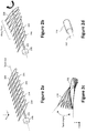
- each wing 104 may include an internal support structure comprising at least one spar 202 operatively coupled to a plurality of ribs 204. At least one of the ribs 204 may be substantially flexible. Alternatively, or additionally, all of the ribs 204 may be flexible. The ribs 204 may have different sizes (and/or shapes, profiles, etc.) depending on their position in the wing 104 and/or the desired size (and/or shape, profile, etc.) of the wing 104 at that position.
- the spar 202 may be configured to be twisted (and/or rotated, turned, etc.) at one or more points along its length by one or more actuators 206, such as a servo actuator.
- the actuator 206 may be positioned, for example, in the fuselage 102 of the aircraft 100. Alternatively, or additionally, the actuator 206 may be positioned, for example, in a wing tip 114 of the aircraft 100.
- the ribs 204 may be coupled to the spar 202 and configured to torsionally rotate (e.g., pivot/twist) about the twist axis with the spar 202 (or portion thereof); where the twist axis is generally defined by the length of the spar 202.
- the degree and location of the twist may be controlled to alter a lift distribution for a given lift coefficient of the wing 104, which could provide aerostructural benefits, such as reduced induced drag and/or tailored load alleviation.
- the ribs 204 may be independently controlled and/or configured with different twist angles to achieve a smooth twist distribution along the length of the wing 104.
- the twist angle generally refers to the angle between the chord at the wing root 109 and the chord of the given rib 204.
- the smooth twist distribution may also alleviate the need to integrate discrete joints and/or other compliant structural features for discontinuous wing twist, which might add weight/complexity to the structure and also increase interference drag due to gaps along the wing from discrete jumps in twist.
- smooth wing twist there are both manufacturing and aero performance related reasons to use smooth wing twist.
- a first spar 202 is positioned in the fuselage 102 and configured to be twisted by an actuator 206.
- the first spar 202 is operatively coupled to a final wing tip 114 rib 208.
- a second spar 210 has a first end operatively coupled to the fuselage, and a second end operatively coupled to the first spar 202.
- the second spar 210 is configured to twist (and/or rotate, revolve, and/or pivot) about the first spar 202.
- the second spar 210 is composed of an outer tube (e.g ., a composite tube) operatively coupled to a plurality (and/or array) of ribs 204.
- the ribs 204 may be designed with specific torsional stiffness characteristics to maintain the shape of the airfoil and to twist the upper and lower wing skins 114 when rotated.
- the second spar 210 may be a tube composite layup conditioned to provide high twist strain.
- the torsional stiffness may be varied along the length to satisfy the aero requirements ( e.g ., more twist at the wingtip).
- the first spar 202 is mounted concentrically within the second spar 210.
- the tensional stiffness of the aircraft's outer mold line (OML) - via the upper and lower wing skins 114 - may be designed to comply with the twist input of the system.
- the first spar 202 and the second spar 210 are substantially rigid, so as to provide the necessary bending stiffness to maintain the structural integrity of the wing (although there is torsional compliance between the spars and along the span of the twisting spar).
- the first spar 202 may be, for example, a torsion bar.
- the second spar 210 may be composed of, for example, polystyrene. Polystyrene may be used, for example, to achieve maximum stiffness along the wingspan (such as to limit out-of-plane bending, for example).
- the second spar may be a carbon fiber rod.
- the materials may be composite and/or homogeneous.
- a single spar 202 may be used where different portions of the spar 202 may be composed of different materials.
- the portion of the spar 202 nearest the fuselage 102 may be different than the portion of the spar 202 nearest the wing tip 114.
- the second spar 210 may be contained within a third spar.
- the actuator 206 may be positioned in and/or near the wing tip 114.
- the actuator 206 may be positioned in and/or near the wing tip 114, and/or be operatively coupled to the wing tip 114 final rib 208 ( e.g ., the rib at the wing tip).
- multiple actuators 206 may be used, with one or more actuators 206 positioned in the fuselage 102, while one or more other actuators 206 are positioned in and/or near the wing tip 114, and/or be operatively coupled to the wing tip 114 final rib 208.
- Twisting of the wing spars 202, 210 (and/or spar 202) and associated ribs 204, via actuator 206, may produce twisting (and/or reshaping, morphing, and/or other change in form) of the wing 104. This twisting may alter, change, and/or modify the shape and/or profile of the wing 104.
- the aircraft 100 may use a control architecture to determine if, when, and/or how to twist the wing 104.
- Figure 3 illustrates a wing-twist control and actuation architecture 300 according to an embodiment of the disclosure.
- the architecture 300 may include wing-twist sensors 302, a wing-twist controller 304, a memory device 305 ( e.g ., having a database 306 thereon), a wing-twist actuation system 308, other aircraft control systems 310, and an autopilot 312.
- the other aircraft control systems 310 may include, for example, a propulsion system 313, the tail 107 and control surfaces 314 associated with the tail 107 (e.g ., rudder(s) and/or elevator(s)), as well as control surfaces 316 associated with the wings 104, such as leading edge devices 110 and/or trailing edge devices and/or control surfaces 112.
- a propulsion system 313 the tail 107 and control surfaces 314 associated with the tail 107
- control surfaces 314 associated with the tail 107 e.g ., rudder(s) and/or elevator(s)
- control surfaces 316 associated with the wings 104, such as leading edge devices 110 and/or trailing edge devices and/or control surfaces 112.
- the aircraft control system may further include other desired services, such as a wireless transceiver coupled with an antenna to communicate data between the aircraft 100 and a remote device (e.g ., portable electronic devices, such as smartphones, tablets, and laptop computers) or other controller (e.g ., a base station).
- a remote device e.g ., portable electronic devices, such as smartphones, tablets, and laptop computers
- controller e.g ., a base station
- the aircraft 100 may communicate data (processed data, unprocessed data, etc.) with the remote device over a network.
- the wireless transceiver may be configured to communicate using one or more wireless standards such as Bluetooth (e.g ., short-wavelength, Ultra-High Frequency (UHF) radio waves in the Industrial, Scientific, and Medical (ISM) band from 2.4 to 2.485 GHz), near-field communication (NFC), Wi-Fi (e.g ., Institute of Electrical and Electronics Engineers' (IEEE) 802.11 standards), etc.
- the remote device may facilitate monitoring and/or control of the aircraft 100 and its payload(s), including an intelligence, surveillance, and reconnaissance (ISR) payload, which may include one or more sensors, communications packages, weapons systems, instruments, antennas, cameras, radars, or other cargo.
- the aircraft processor may be communicatively coupled with one or more feedback sensors, including, for example, strain gauges, differential pressure sensors, etc.
- Figure 1c illustrates the BWB aircraft 100 having a plurality of sensors 302 therein and/or thereon.
- the aircraft 100 may use a plurality (and/or series, array etc.) of sensors 302 to determine (and/or detect, sense, and/or otherwise measure) a characteristic of the wing 104, such as, for example, an angle of attack across the wingspan, an aerodynamic characteristic of the wing, a behavioral characteristic of the wing, an aeroelastic characteristic of the wing 104, and/or a structural characteristic of the wing.
- the sensors 302 may relay this information to an autopilot 312 and/or controller 304 to determine appropriate wing-twist, and direct twisting of the wing 104 accordingly.
- the sensors 302 may be positioned throughout the aircraft 100, both within the aircraft 100 and/or on the exterior skin 114 of the aircraft.
- the sensors 302 may be positioned on and/or within the fuselage 102, the wings 104, and/or the tail 107 of the aircraft 100.
- the sensors 302 may be positioned on and/or within the wing 104 leading edge devices 110 and/or trailing edge devices and control surfaces 112.
- the sensors 302 may be positioned on and/or within the wing tips 114.
- the sensors 302 may be operatively coupled to a power system of the aircraft 100, and/or powered by an alternative source.
- the sensors 302 may be connected to one another in distributed network. In some embodiments, some sensors 302 may be networked while other sensors 302 are isolated.
- the sensors 302 may include, for example, inertial measurement units (IMUs), Global Positioning System (GPS) sensors, accelerometers (e.g ., ADXL345 accelerometers), gyroscopes (e.g ., HMC5883L gyros), magnetometers (e.g ., ITG-3200 magnetometers), fluid sensors, strain gauges, differential pressure sensors, etc.
- IMUs inertial measurement units
- GPS Global Positioning System
- accelerometers e.g ., ADXL345 accelerometers
- gyroscopes e.g ., HMC5883L gyros
- magnetometers e.g ., ITG-3200 magnetometers
- fluid sensors e.g ., strain gauges, differential pressure sensors, etc.
- an array/system of strain gauges and/or pressure sensors may be provided to collect a plurality of strain and/or differential pressure measurements along the span of the wing 104.
- the wing 104 may utilize a continuous set of sensors (e.g., strain/torque measurement sensors) along the wing to provide feedback to the controller 304.
- the sensors e.g ., fiber optic strain gauges
- the sensors may be embedded within micro-grooves or notches ( e.g ., defined through a 3D printing process). Further, the sensors may be embedded in the top and/or bottom of the wing to obtain numerous torque measurements for use in stabilization.
- the placement of the grooves may be determined to ensure that the fiber optic sensor yields evenly distributed, span-wise measurements, in addition to measurements for precise locations.
- the placement of the grooves may be determined by so as to facilitate even distribution of sensor measurements.
- an example distributed pressure sensor system is described in greater detail by commonly owned U.S. Patent Application No. 62/454,188 to Riley Griffin et al., which was filed on February 3, 2017 and is titled "System and Method for Distributed Airflow Sensing.”
- the controller 304 may employ a processor or microcontroller unit (MCU) implemented using, for example, a BeagleBone or BeagleBoard.
- MCU microcontroller unit
- the controller 304 may further include one or more driver circuits to facilitate control of the various components thought, for example, a processor.
- the controller 304 may use information provided by the sensors 302 to recognize and/or determine oncoming stall risks, for example.
- the controller 304 may further command the actuation system 308 to actively twist the wing 104 in response to the input from the sensors 302 and/or determination of an oncoming stall risk, as well as in response to input from a pilot (and/or navigator) and/or autopilot 312.
- the controller 304 and the autopilot 312 may communicate via Micro Air Vehicle Links (MAVlink) protocol over a serial port.
- the controller 304 and autopilot 312 may additionally, or alternatively, communicate using a universal asynchronous receiver/transmitter (UART).
- UART universal asynchronous receiver/transmitter
- the autopilot 312 may be a Pixhawk, for example.
- the autopilot 312 may be configured to perform rigid body control and/or determine the necessary and/or desired yaw, pitch, and roll of the aircraft 100.
- the autopilot 312 may be configured to consider and/or respond to pilot 402 (and/or navigator, operator, etc.) input.
- the autopilot 312 may take into consideration the input of the pilot 402 when performing rigid body control and/or determining a necessary and/or desired yaw, pitch, and roll of the aircraft 100.
- the autopilot 312 may be additionally, or alternatively, configured to operate substantially autonomously.
- the autopilot 312 may also be configured to receive and/or operate on sensor 302 input.
- the autopilot 312 may use sensor 302 inputs in conjunction with pilot 402 input and/or autonomous processes to perform rigid body control and/or determine the necessary and/or desired yaw, pitch, and roll of the aircraft 100.
- the autopilot 312 may output a command signal to the other aircraft control systems 310 to maneuver the aircraft 100 accordingly.
- the autopilot 312 may be tuned using proportional-integral-derivative (PID) gain controllers for flight.
- PID controllers may be configured to output desired control surface positions, which may then passed from the autopilot 312 to the wing-twist controller 304 and/or the other aircraft control systems 310.
- the controller 304 may also communicate with a memory device 305 having software and/or a database 306 stored thereon.
- the database 306 may be a relational database, a non-relational database, or some other sort of database.
- the database 306 may be populated with information helpful to the controller 304, such as a collection of aerodynamic control derivatives related to the aircraft 100.
- the control derivatives may be generated through the use of simulations and/or tests.
- the aerodynamic derivatives may be estimated via a combination of wind tunnel and flight testing.
- the database 306 may be prepopulated with data and/or populated with data during flight.
- the database 306 may be used to estimate a partial derivative of a non-linear aeroelastic equation to assist the controller 304 in controlling wing-twist.
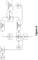
- Figure 4 illustrates the wing-twist control and actuation architecture 300 in more detail, according to an embodiment of the disclosure.
- the autopilot 312 may communicate with the other control systems of the aircraft 100 to maneuver the aircraft 100.
- the autopilot 312 may use one or more pulse width modulated (PWM) signals to communicate with the other control systems 310 of the aircraft.
- PWM pulse width modulated
- the autopilot 312 may also communicate with the controller 304. More particularly, the autopilot 312 may output a PWM command signal to a PWM command converter 404, which may convert the signal into a form readable by the controller 304.
- the controller 304 may use the autopilot 312 determined rigid body control and/or desired yaw, pitch, and roll of the aircraft 100 as input to its determination of appropriate wing-twist.
- the controller 304 may further perform analysis, comparisons, and/or interpretation of data in the database 306 in its determination of appropriate wing-twist.
- the controller 304 may use sensor 302 data in its determination. As shown in Figure 4 , the sensor 302 data may be operated on by a filter 406 before being used by the controller 304.
- the controller 304 may output one or more control signals to the twist actuation system 308 to affect appropriate wing-twist. This may be performed substantially concurrently with the autopilot 312 command signals to the other control systems 310, such that maneuvering of the aircraft 100 is performed in concert. Maneuvering of the aircraft 100 is performed at 408 in Figure 4 . Subsequent environmental changes in aircraft 100 rigid body dynamics, angle of attack, aerodynamic characteristics, behavioral characteristics, aeroelastic characteristics, structural characteristics, and/or aeroelastic dynamics take place at 410 in Figure 4 . These changes may be sensed by the sensors 302, and fed back in a feedback loop to the autopilot 312 and controller 304 to make further determinations, commands, and/or decisions.
- the twist controller 304 may use an aeroelastic model.
- LQ linear quadratic
- the autopilot 312 may output a PWM command signal to a PWM command converter 404, which may convert the signal into a form readable by the controller 304.
- the PWM signals may be transmitted using Micro Air Vehicle Link (MAVLink) protocols and/or packages.
- MAVLink Micro Air Vehicle Link
- a software architecture may be used to interpret and communicate the MAVLink transmissions.
- the controller 304 may use a hybrid Kalman filter 406 to assist in interpretation of sensor 302 information.
- the Kalman filter 406 may be compiled into a single class for modularity and re-usability of the code base.
- This Kalman gain may then be used to create an estimate of the state and covariance matrix.
- k X ⁇ k
- k I ⁇ K k C P k
- the sensors 302 may detect (and/or sense, measure, etc.) rigid body dynamics, angle of attack, aerodynamic characteristics, behavioral characteristics, aeroelastic characteristics, structural characteristics, and/or aeroelastic dynamics of the aircraft 100 (and/or the wings 104 of the aircraft).
- the sensors 302 may relay this information to the controller 304 and/or the autopilot 312.
- the autopilot 312 may use this information along with input from the pilot 402 and/or its own autonomous systems to determine the necessary and/or desired yaw, pitch, and roll of the aircraft 100.
- the autopilot 312 may output a command signal to the other aircraft control systems 310 to maneuver the aircraft 100 accordingly.
- the autopilot 312 may additionally output the signal, and/or some other signal to the controller 304.
- the controller 304 may receive the signal from the autopilot 312 as input (potentially after some conversion, modification, interpretation, and/or other processes) and use the information to determine appropriate wing-twist. The controller 304 may then output a control signal to the wing-twist actuation system 308, which may twist the wing 104 via the spar 202 (and/or spars 202, 210) and associated ribs 204. The twisting of the wing 104 in conjunction with the use of the other control systems 310 of the aircraft 100 may maneuver the aircraft 100 during flight.
- an autonomous flight controller can mitigate an accelerated spin by twisting a wing 104 and/or wing tip 114 that has an excessive angle of attack. This may avoid the need to pitch the aircraft down. This may be especially relevant when the aircraft is close to the ground.
- This control strategy may also reduce a design compromise between cruise and climb, particularly when used with a BWB aircraft. The normal constraints of the BWB layout, which use the large centerbody/payload area of the aircraft as a lifting body, are minimized with the twisted wing control strategy. Further, this control strategy may produce yaw with lower drag than rudder-induced yaw.
- proverse yaw may allow yaw maneuvering without roll, as well as coordinated turns with lower drag than a rudder coordinated turn. If proverse yaw is used then the rudder and its associated wetted area can be eliminated, reducing drag and increasing fuel efficiency. Further, it would be possible to use active proverse yaw for stability; eliminating and/or substantially reducing the need for a vertical stabilizer.
Landscapes
- Engineering & Computer Science (AREA)
- Aviation & Aerospace Engineering (AREA)
- Mechanical Engineering (AREA)
- Radar, Positioning & Navigation (AREA)
- Remote Sensing (AREA)
- Physics & Mathematics (AREA)
- General Physics & Mathematics (AREA)
- Automation & Control Theory (AREA)
- Toys (AREA)
- Aerodynamic Tests, Hydrodynamic Tests, Wind Tunnels, And Water Tanks (AREA)
- Structures Of Non-Positive Displacement Pumps (AREA)
Description
- The present disclosure relates to an aircraft having a flexible wing, an active wing-twist mechanism, and control system thereof.
- In general, static wing tip twist (washout) is used to initiate stall at the wing root, leaving the control surfaces at the outer wing functional. This allows the pilot to recover using the outer wing control surfaces. But a wing setup with static twist to mitigate stall can only be optimized for a narrow flight region. This situation is intensified with blended wing body (BWB) aircraft: to accommodate a payload the center-body airfoils may be thick. Thick airfoils stall at a higher angle of attack than thinner airfoils, assuming both are similar and well suited for the aircraft. This thickness discrepancy leads to the outer wings and the associated control surfaces stalling first. Stalled control surfaces are typically a non-recoverable event for a BWB.
- Fixed wing vehicles use coordinated turns to mitigate stall. A coordinated turn with conventional control surfaces will bank the vehicle with aileron input and, in order to mitigate the onset of an accelerated spin, the rudder is used to keep the inside wing from slipping down. However, the presence of a rudder creates constant additional drag area that decreases the aerodynamic efficiency for all operating points. Thus, a need exists for an aircraft, active wing-twist mechanism, and/or control system that can overcome the deficiencies of the prior art.
US2008/149779 describes a method and apparatus for varying the twist of a wing such that induced drag is minimized or reduced during cruise and lift is maximized or increased at least during takeoff and landings. In addition, variations in the twist may produce yawing and rolling moments. The twist amount is varied pursuant to the operating conditions, including those parameters used to determine the lift coefficient. The twist for reducing induced drag and/or improving lift may be employed by geometric or aerodynamic twist, including full span control surfaces used to provide roll control, high-lift and reduced induced drag. The twist may also be employed by twisting just a portion of the wing or the entire wing, either geometrically or aerodynamically.US2016/001874 describes active strut apparatus for use with aircraft and related methods. An example apparatus includes a first strut having a first end and a second end opposite the first end, the first end of the first strut is operatively coupled to a fuselage of an aircraft and the second end of the first strut is operatively coupled to a wing of the aircraft, and a first actuator is operatively coupled to the first strut to change an effective length of the first strut. - The present disclosure relates to an active wing-twist mechanism and control system.
- One aspect of the disclosure involves an aircraft with an active wing-twist control system that includes a flexible wing defined by a wingspan, wherein the flexible wing comprises a first spar positioned in a fuselage of the aircraft and aligned in a span-wise direction, wherein a final wing tip rib is operatively coupled to the first spar; an actuation system to torsionally rotate the first spar about a twist axis, which, in turn, causes the final wing tip rib coupled to the first spar to rotate, thereby twisting at least a portion of the flexible wing; a sensor configured to measure a characteristic of the flexible wing; and a controller configured to command the actuation system to rotate the first spar based at least in part on input from the sensor. The flexible wing further comprises a second spar having a first end operatively coupled to the fuselage and a second end operatively coupled to the first spar, such that the second spar is configured to twist, rotate, revolve and/or pivot about the first spar. The second spar comprises an outer tube operatively coupled to a plurality of ribs, and the first spar is mounted concentrically within the second spar.
- Another aspect of the disclosure involves a method of controlling a wing-twist of an aircraft as described above, the method including the steps of: sensing a characteristic of the flexible wing; determining an appropriate wing-twist based at least in part on the sensed characteristic of the flexible wing; and rotating the first spar of the flexible wing based at least in part on the appropriate wing-twist determination, wherein the first spar and the final wing tip rib at least partly define a shape of the flexible wing, and wherein the shape of the flexible wing is altered by rotation of the first spar.
- The foregoing and other objects, features, and advantages of the devices, systems, and methods described herein will be readily understood from the following description of particular embodiments thereof, as illustrated in the accompanying figures, where like reference numbers refer to like structures. The figures are not necessarily to scale, emphasis instead being placed upon illustrating the principles of the devices, systems, and methods described herein.
-
Figure 1a illustrates an isometric view of a BWB aircraft. -
Figure 1b illustrates a front view of a BWB aircraft -
Figure 1c illustrates an isometric view of a BWB aircraft according to an embodiment of the disclosure. -
Figure 2a illustrates an isometric view of internal wing components. -
Figures 2b and 2c illustrate, respectively, an isometric and a side view of internal wing components during a wing-twist. -
Figure 2d illustrates an enlarged view of a portion of the internal wing components. -
Figure 3 is a diagram illustrating an active wing-twist control system. -
Figure 4 is a more detailed diagram illustrating the active wing control system - Preferred embodiments of the present disclosure will be described herein below with reference to the accompanying drawings. The components in the drawings are not necessarily drawn to scale, the emphasis instead being placed upon clearly illustrating the principles of the present embodiments. For instance, the size of an element may be exaggerated for clarity and convenience of description. Moreover, wherever possible, the same reference numbers are used throughout the drawings to refer to the same or like elements of an embodiment. In the following description, well-known functions or constructions are not described in detail because they may obscure the disclosure in unnecessary detail. No language in the specification should be construed as indicating any unclaimed element as essential to the practice of the embodiments. In the following description, it is understood that terms such as "first," "second," "top," "bottom," "side," "front," "back," and the like, are words of convenience and are not to be construed as limiting terms. For this application, the following terms and definitions shall apply:
- As utilized herein, "and/or" means any one or more of the items in the list joined by "and/or". As an example, "x and/or y" means any element of the three-element set {(x), (y), (x, y)}. In other words, "x and/or y" means "one or both of x and y". As another example, "x, y, and/or z" means any element of the seven-element set {(x), (y), (z), (x, y), (x, z), (y, z), (x, y, z)}. In other words, "x, y and/or z" means "one or more of x, y and z".
- The terms "about" and "approximately," when used to modify or describe a value (or range of values), mean reasonably close to that value or range of values. Thus, the embodiments described herein are not limited to only the recited values and ranges of values, but rather should include reasonably workable deviations
- The term "aircraft" refers to a machine capable of flight, including, but not limited to, BWB aircraft, traditional aircraft, unmanned aerial vehicles (UAVs), drones, and vertical take-off and landing (VTOL) aircraft, such as rotorcraft (e.g., helicopters) and/or tilt-rotor/tilt-wing aircraft.
- The terms "communicate" and "communicating" refer to (1) transmitting, or otherwise conveying, data from a source to a destination, and/or (2) delivering data to a communications medium, system, channel, network, device, wire, cable, fiber, circuit, and/or link to be conveyed to a destination.
- The term "composite material" as used herein, refers to a material comprising an additive material and a matrix material. For example, a composite material may comprise a fibrous additive material (e.g., fiberglass, glass fiber ("GF"), carbon fiber ("CF"), aramid/para aramid synthetic fibers, etc.) and a matrix material (e.g., epoxies, polyimides, and alumina, including, without limitation, thermoplastic, polyester resin, polycarbonate thermoplastic, casting resin, polymer resin, acrylic, chemical resin). In certain aspects, the composite material may employ a metal, such as aluminum and titanium, to produce fiber metal laminate (FML) and glass laminate aluminum reinforced epoxy (GLARE). Further, composite materials may include hybrid composite materials, which are achieved via the addition of some complementary materials (e.g., two or more fiber materials) to the basic fiber/epoxy matrix.
- The terms "coupled," "coupled to," and "coupled with" as used herein, each mean a relationship between or among two or more devices, apparatuses, files, circuits, elements, functions, operations, processes, programs, media, components, networks, systems, subsystems, and/or means, constituting any one or more of: (i) a connection, whether direct or through one or more other devices, apparatuses, files, circuits, elements, functions, operations, processes, programs, media, components, networks, systems, subsystems, or means; (ii) a communications relationship, whether direct or through one or more other devices, apparatuses, files, circuits, elements, functions, operations, processes, programs, media, components, networks, systems, subsystems, or means; (iii) a functional relationship in which the operation of any one or more devices, apparatuses, files, circuits, elements, functions, operations, processes, programs, media, components, networks, systems, subsystems, or means depends, in whole or in part, on the operation of any one or more others thereof; and/or (iv) a structural connection, whether attached, affixed, connected, joined, fastened, linked, and/or otherwise secured.
- The term "data" as used herein means any indicia, signals, marks, symbols, domains, symbol sets, representations, and any other physical form or forms representing information, whether permanent or temporary, whether visible, audible, acoustic, electric, magnetic, electromagnetic, or otherwise manifested. The term "data" is used to represent predetermined information in one physical form, encompassing any and all representations of corresponding information in a different physical form or forms.
- The term "database" as used herein means an organized body of related data, regardless of the manner in which the data or the organized body thereof is represented. For example, the organized body of related data may be in the form of one or more of a table, a map, a grid, a packet, a datagram, a frame, a file, an e-mail, a message, a document, a report, a list, or data presented in any other form.
- The term "exemplary" means serving as a non-limiting example, instance, or illustration. As utilized herein, the terms "e.g.," and "for example" set off lists of one or more non-limiting examples, instances, or illustrations.
- The term "memory device" means computer hardware or circuitry to store information for use by a processor. The memory device can be any suitable type of computer memory or any other type of electronic storage medium, such as, for example, read-only memory (ROM), random access memory (RAM), cache memory, compact disc read-only memory (CDROM), electro-optical memory, magneto-optical memory, programmable read-only memory (PROM), erasable programmable read-only memory (EPROM), electrically-erasable programmable read-only memory (EEPROM), a computer-readable medium, or the like.
- The term "network" as used herein includes both networks and inter-networks of all kinds, including the Internet, and is not limited to any particular network or inter-network.
- The term "processor" means processing devices, apparatuses, programs, circuits, components, systems, and subsystems, whether implemented in hardware, tangibly embodied software, or both, and whether or not it is programmable. The term "processor" as used herein includes, but is not limited to, one or more computing devices, hardwired circuits, signal-modifying devices and systems, devices and machines for controlling systems, central processing units, programmable devices and systems, field-programmable gate arrays, application-specific integrated circuits, systems on a chip, systems comprising discrete elements and/or circuits, state machines, virtual machines, data processors, processing facilities, and combinations of any of the foregoing. The processor may be, for example, any type of general purpose microprocessor or microcontroller, a digital signal processing (DSP) processor, an application-specific integrated circuit (ASIC). The processor may be coupled to, or integrated with a memory device.
- Disclosed herein is a system for active wing-twist control. With active wing-twist, the area critical to accelerated stall mitigation, and the area where the control surfaces reside, is actively twisted to increase downwash. Using active wing-twist, an autonomous flight controller may mitigate an accelerated spin by twisting the wing (and/or wing tip) that has an excessive angle of attack. This may avoid the need to pitch the aircraft down. This may be especially relevant when the aircraft is close to the ground. Not only does this allow for active stall mitigation, but it allows autonomous systems to mitigate an accelerated stall without pitching the aircraft below zero alpha.
- Active wing-twist may eliminate adverse yaw produced by induced drag and create proverse yaw with induced thrust. If proverse yaw is used, then the rudder and its associated area may be able to be reduced or eliminated; reducing drag and increasing fuel efficiency. Typically a rudder is used to counter adverse yaw, but active wing-twist may produce yaw with lower drag than rudder-induced yaw. Further, it may be possible to use active proverse yaw for stability; reducing or eliminating the need for a vertical stabilizer. Active wing-twist may allow yaw maneuvering without roll, while also allowing turn coordination with lower drag than a rudder coordinated turn.
- Active wing-twist may be especially relevant to manned autonomous flight and fully autonomous flight systems. The system may also be ideal for blended wing body (BWB) aircraft, though those of ordinary skill in the art will recognize that the system may be applied to traditional aircraft and others type of aircraft as well. Active wing-twist may reduce the design compromise between cruise and climb, particularly when used with a BWB aircraft. The normal constraints of the BWB layout, which may use a large centerbody/payload area of the aircraft as a lifting body, may be minimized with the twisted wing control strategy.
- The disclosed active wing-twist control system may use a torsionally compliant wing structure integrated with an active twist control architecture to actively control the twist along a wing as commanded during flight operations. The technology may allow for a mitigation of the stall characteristics typically exhibited by BWB aircraft without the need to washout the wingtips at cruise, thereby resulting in a significant increase in aerodynamic efficiency throughout the majority of the flight envelope. Moreover, the ability to tailor the span-wise lift distribution across the wing throughout the flight envelope has the potential to greatly improve aerodynamic performance of aircraft - both conventional and BWB - that have to perform at vastly different points in their flight envelope over a single mission. Furthermore, differential twisting across the wing provides proverse yaw capabilities during a turn, thereby providing a means to perform coordinated turns with smaller or potentially no vertical tail augmentation, which reduces the wetted area (i.e., parasitic drag) of the aircraft. A compliant wing architecture that provides active control of the twist along the span of the wing by sensing and appropriately responding to oncoming stall risks may eliminate the need for outer wing washout and drastically improving the aerodynamic performance of the wing during cruise. The system may further allow significant thickness differences across the wingspan (resulting in payload-carrying capabilities and profile drag reduction) without the risk (and/or with reduced risk) of stall during low-speed operations. Additionally, a compliant internal wing structure can be coupled with an adaptive wing control systems to gain efficiencies in other ways, such as through local gust load alleviation.
-
Figure 1a shows an embodiment of the present disclosure where active wing-twist is used with aBWB aircraft 100. As illustrated, theaircraft 100 may generally comprise afuselage 102 operatively coupled to a pair ofwings 104. Thefuselage 102, as illustrated, includes a nose (or forward)portion 103 and a rear (or aft)portion 105. The aircraft may further include a tail (or empennage) 107 operatively coupled to thefuselage 102 at and/or near the aft 105 portion of thefuselage 102. Theaircraft 100, may further comprise landing gear. For example, a set of wheels and/or skids may be provided on thefuselage 102 and/or thewings 105. Preferably, at least one wheel or skid is steerable. As illustrated, for example, the tail 1 07 may include a horizontal stabilizer supported by a pair ofparallel tail booms 111. - The
wings 104 may have a wingspan extending from awing root 109 to awing tip 114. Thefuselage 102 andwings 104 may be blended together at and/or near thewing root 109 such that it is difficult to define a specific point at which thefuselage 102 ends and thewing root 109 begins. Eachwing 104 may also include aleading edge 106 and a trailingedge 108. Eachwing 104 may further include one or more leading edge devices and/orcontrol surfaces 110, such as slats, and/or one or more trailing edge devices and/orcontrol surfaces 112, such as ailerons, flaps, flaperons etc. - As illustrated in
Figure 1b , the internal components of theaircraft 100 are generally covered (and/or concealed, shielded, etc.) by an external skin (and/or shell) 114, which may be fabricated from a substantially solid aerodynamic material. The various structural components of theaircraft 100 may be fabricated from metal, a composite material, or a combination thereof. For example, theaircraft skin 114 may comprise a thermoplastic polystyrene material. Alternatively, or additionally, theaircraft skin 114 may comprise a metal material, such as, but not limited to, aluminum, titanium, steel, or alloys thereof. Alternatively, or additionally, theaircraft skin 114 may be constructed using composite material such as, but not limited to, fiberglass. As a further alternative, theaircraft skin 114 may be a blend of multiple materials. Some portions of theaircraft skin 114 may be composed of different material than other portions. For example, thewing 104 and/ortail 107skins 114 may be composed of more flexible material than other portions of theaircraft 100, so as to allow for wing-twisting (and/or morphing, reshaping, etc.). In an exemplary example, the wing skin (e.g., the upper and lower wing skins 114) is substantially flexible and/or compliant such that it does not buckle or tear as the wing twists across the span. - In another example, the
aircraft 100, or a component thereof, may be fabricated using fused deposition modeling (FDM), stereolithography (SLA), selective laser sintering (SLS), and/or any other suitable type of additive manufacturing/3D printing. A benefit of this fabrication method is that it produces a high-performing, more stable aircraft, using advanced sensing and 3D printing disciplines. FDM is a thermal polymer layer deposition process that produces parts one layer at a time, effectively printing aircraft components rapidly, in low-volume, and to exacting material specifications. Using FDM, numerous wing design iterations may be inexpensively manufactured to meet desired strength and stiffness requirements, control surface sizing, and other characteristics. Further, additional wings may be fabricated to allow for tailored sensor integration, ease of generating additional actuation schemes or altering the control surface placement, ease of characterizing the strain on the wing, and an ability to easily alter the wing's stiffness to provide the best platform for proprioceptive sensing in a given application. This capability also offers robustness against wing damage, as replacement components are readily reproducible. Additionally, this capability may allow for 3D printing a wing section (e.g. the wingtip) and actively twist the section (possibly with a constant wing washout at the tip) - As illustrated in
Figure 2a , eachwing 104 may include an internal support structure comprising at least onespar 202 operatively coupled to a plurality ofribs 204. At least one of theribs 204 may be substantially flexible. Alternatively, or additionally, all of theribs 204 may be flexible. Theribs 204 may have different sizes (and/or shapes, profiles, etc.) depending on their position in thewing 104 and/or the desired size (and/or shape, profile, etc.) of thewing 104 at that position. Thespar 202 may be configured to be twisted (and/or rotated, turned, etc.) at one or more points along its length by one ormore actuators 206, such as a servo actuator. Theactuator 206 may be positioned, for example, in thefuselage 102 of theaircraft 100. Alternatively, or additionally, theactuator 206 may be positioned, for example, in awing tip 114 of theaircraft 100. - As illustrated in
Figures 2b and 2c , theribs 204 may be coupled to thespar 202 and configured to torsionally rotate (e.g., pivot/twist) about the twist axis with the spar 202 (or portion thereof); where the twist axis is generally defined by the length of thespar 202. The degree and location of the twist may be controlled to alter a lift distribution for a given lift coefficient of thewing 104, which could provide aerostructural benefits, such as reduced induced drag and/or tailored load alleviation. In certain aspects, theribs 204 may be independently controlled and/or configured with different twist angles to achieve a smooth twist distribution along the length of thewing 104. For a givenrib 204, as best illustrated inFigure 2c , the twist angle generally refers to the angle between the chord at thewing root 109 and the chord of the givenrib 204. By controlling the twist of thewing 104 usingmultiple ribs 204 distributed (e.g., evenly distributed) at multiple locations along the length of the spar 202 (and the wing 104), a gradual smooth variation in twist results between thewing root 109 and thefinal wing tip 114. The smooth twist distribution may allow for easier manufacture because it allows a gradual change across the compliant structure (i.e., the compliant wing skin), which limits the potential for the wing skin to buckle (i.e., warp to produce drag increases). The smooth twist distribution may also alleviate the need to integrate discrete joints and/or other compliant structural features for discontinuous wing twist, which might add weight/complexity to the structure and also increase interference drag due to gaps along the wing from discrete jumps in twist. Thus, there are both manufacturing and aero performance related reasons to use smooth wing twist. - In one embodiment, as illustrated in
Figure 2d , multiple spars are used. For example, afirst spar 202 is positioned in thefuselage 102 and configured to be twisted by anactuator 206. Thefirst spar 202 is operatively coupled to afinal wing tip 114rib 208. Asecond spar 210 has a first end operatively coupled to the fuselage, and a second end operatively coupled to thefirst spar 202. Thesecond spar 210 is configured to twist (and/or rotate, revolve, and/or pivot) about thefirst spar 202. Thesecond spar 210 is composed of an outer tube (e.g., a composite tube) operatively coupled to a plurality (and/or array) ofribs 204. Theribs 204 may be designed with specific torsional stiffness characteristics to maintain the shape of the airfoil and to twist the upper andlower wing skins 114 when rotated. Thesecond spar 210 may be a tube composite layup conditioned to provide high twist strain. The torsional stiffness may be varied along the length to satisfy the aero requirements (e.g., more twist at the wingtip). Thefirst spar 202 is mounted concentrically within thesecond spar 210. The tensional stiffness of the aircraft's outer mold line (OML) - via the upper and lower wing skins 114 - may be designed to comply with the twist input of the system. - In an exemplary example, the
first spar 202 and thesecond spar 210 are substantially rigid, so as to provide the necessary bending stiffness to maintain the structural integrity of the wing (although there is torsional compliance between the spars and along the span of the twisting spar). Thefirst spar 202 may be, for example, a torsion bar. Thesecond spar 210 may be composed of, for example, polystyrene. Polystyrene may be used, for example, to achieve maximum stiffness along the wingspan (such as to limit out-of-plane bending, for example). Alternatively, or additionally, the second spar may be a carbon fiber rod. The materials may be composite and/or homogeneous. Alternatively, or additionally, asingle spar 202 may be used where different portions of thespar 202 may be composed of different materials. For example, the portion of thespar 202 nearest thefuselage 102 may be different than the portion of thespar 202 nearest thewing tip 114. In some embodiments, thesecond spar 210 may be contained within a third spar. In some embodiments, theactuator 206 may be positioned in and/or near thewing tip 114. In some embodiments, theactuator 206 may be positioned in and/or near thewing tip 114, and/or be operatively coupled to thewing tip 114 final rib 208 (e.g., the rib at the wing tip). In some embodiments,multiple actuators 206 may be used, with one ormore actuators 206 positioned in thefuselage 102, while one or moreother actuators 206 are positioned in and/or near thewing tip 114, and/or be operatively coupled to thewing tip 114final rib 208. - Twisting of the wing spars 202, 210 (and/or spar 202) and associated
ribs 204, viaactuator 206, may produce twisting (and/or reshaping, morphing, and/or other change in form) of thewing 104. This twisting may alter, change, and/or modify the shape and/or profile of thewing 104. Theaircraft 100 may use a control architecture to determine if, when, and/or how to twist thewing 104. -
Figure 3 illustrates a wing-twist control andactuation architecture 300 according to an embodiment of the disclosure. As illustrated, thearchitecture 300 may include wing-twist sensors 302, a wing-twist controller 304, a memory device 305 (e.g., having adatabase 306 thereon), a wing-twist actuation system 308, otheraircraft control systems 310, and anautopilot 312. The otheraircraft control systems 310 may include, for example, apropulsion system 313, thetail 107 andcontrol surfaces 314 associated with the tail 107 (e.g., rudder(s) and/or elevator(s)), as well ascontrol surfaces 316 associated with thewings 104, such asleading edge devices 110 and/or trailing edge devices and/or control surfaces 112. - The aircraft control system may further include other desired services, such as a wireless transceiver coupled with an antenna to communicate data between the
aircraft 100 and a remote device (e.g., portable electronic devices, such as smartphones, tablets, and laptop computers) or other controller (e.g., a base station). For example, theaircraft 100 may communicate data (processed data, unprocessed data, etc.) with the remote device over a network. In certain aspects, the wireless transceiver may be configured to communicate using one or more wireless standards such as Bluetooth (e.g., short-wavelength, Ultra-High Frequency (UHF) radio waves in the Industrial, Scientific, and Medical (ISM) band from 2.4 to 2.485 GHz), near-field communication (NFC), Wi-Fi (e.g., Institute of Electrical and Electronics Engineers' (IEEE) 802.11 standards), etc. The remote device may facilitate monitoring and/or control of theaircraft 100 and its payload(s), including an intelligence, surveillance, and reconnaissance (ISR) payload, which may include one or more sensors, communications packages, weapons systems, instruments, antennas, cameras, radars, or other cargo. The aircraft processor may be communicatively coupled with one or more feedback sensors, including, for example, strain gauges, differential pressure sensors, etc. -
Figure 1c illustrates theBWB aircraft 100 having a plurality ofsensors 302 therein and/or thereon. Theaircraft 100 may use a plurality (and/or series, array etc.) ofsensors 302 to determine (and/or detect, sense, and/or otherwise measure) a characteristic of thewing 104, such as, for example, an angle of attack across the wingspan, an aerodynamic characteristic of the wing, a behavioral characteristic of the wing, an aeroelastic characteristic of thewing 104, and/or a structural characteristic of the wing. Thesensors 302 may relay this information to anautopilot 312 and/orcontroller 304 to determine appropriate wing-twist, and direct twisting of thewing 104 accordingly. - The
sensors 302 may be positioned throughout theaircraft 100, both within theaircraft 100 and/or on theexterior skin 114 of the aircraft. Thesensors 302 may be positioned on and/or within thefuselage 102, thewings 104, and/or thetail 107 of theaircraft 100. Thesensors 302 may be positioned on and/or within thewing 104leading edge devices 110 and/or trailing edge devices and control surfaces 112. Thesensors 302 may be positioned on and/or within thewing tips 114. Thesensors 302 may be operatively coupled to a power system of theaircraft 100, and/or powered by an alternative source. Thesensors 302 may be connected to one another in distributed network. In some embodiments, somesensors 302 may be networked whileother sensors 302 are isolated. In some embodiments, somesensors 302 may be networked and those sensor networks may be isolated fromother sensor 302 networks and/or otherstandalone sensors 302. In some embodiments, all thesensors 302 may be networked together. Thesensors 302 may include, for example, inertial measurement units (IMUs), Global Positioning System (GPS) sensors, accelerometers (e.g., ADXL345 accelerometers), gyroscopes (e.g., HMC5883L gyros), magnetometers (e.g., ITG-3200 magnetometers), fluid sensors, strain gauges, differential pressure sensors, etc. - In certain aspects, an array/system of strain gauges and/or pressure sensors may be provided to collect a plurality of strain and/or differential pressure measurements along the span of the
wing 104. For example, thewing 104 may utilize a continuous set of sensors (e.g., strain/torque measurement sensors) along the wing to provide feedback to thecontroller 304. The sensors (e.g., fiber optic strain gauges) may be embedded within micro-grooves or notches (e.g., defined through a 3D printing process). Further, the sensors may be embedded in the top and/or bottom of the wing to obtain numerous torque measurements for use in stabilization. The placement of the grooves may be determined to ensure that the fiber optic sensor yields evenly distributed, span-wise measurements, in addition to measurements for precise locations. The placement of the grooves may be determined by so as to facilitate even distribution of sensor measurements. In addition, an example distributed pressure sensor system is described in greater detail by commonly ownedU.S. Patent Application No. 62/454,188 to Riley Griffin et al., which was filed on February 3, 2017 - Information outputted by the wing-
twist sensors 302 may be used as input to theautopilot 312 and/or thecontroller 304. Thecontroller 304 may employ a processor or microcontroller unit (MCU) implemented using, for example, a BeagleBone or BeagleBoard. Thecontroller 304 may further include one or more driver circuits to facilitate control of the various components thought, for example, a processor. Thecontroller 304 may use information provided by thesensors 302 to recognize and/or determine oncoming stall risks, for example. Thecontroller 304 may further command theactuation system 308 to actively twist thewing 104 in response to the input from thesensors 302 and/or determination of an oncoming stall risk, as well as in response to input from a pilot (and/or navigator) and/orautopilot 312. - The
controller 304 and theautopilot 312 may communicate via Micro Air Vehicle Links (MAVlink) protocol over a serial port. Thecontroller 304 andautopilot 312 may additionally, or alternatively, communicate using a universal asynchronous receiver/transmitter (UART). Theautopilot 312 may be a Pixhawk, for example. Theautopilot 312 may be configured to perform rigid body control and/or determine the necessary and/or desired yaw, pitch, and roll of theaircraft 100. Theautopilot 312 may be configured to consider and/or respond to pilot 402 (and/or navigator, operator, etc.) input. For example, theautopilot 312 may take into consideration the input of thepilot 402 when performing rigid body control and/or determining a necessary and/or desired yaw, pitch, and roll of theaircraft 100. Theautopilot 312 may be additionally, or alternatively, configured to operate substantially autonomously. Theautopilot 312 may also be configured to receive and/or operate onsensor 302 input. In particular, theautopilot 312 may usesensor 302 inputs in conjunction withpilot 402 input and/or autonomous processes to perform rigid body control and/or determine the necessary and/or desired yaw, pitch, and roll of theaircraft 100. Once the determination is made, theautopilot 312 may output a command signal to the otheraircraft control systems 310 to maneuver theaircraft 100 accordingly. Theautopilot 312 may be tuned using proportional-integral-derivative (PID) gain controllers for flight. The PID controllers may be configured to output desired control surface positions, which may then passed from theautopilot 312 to the wing-twist controller 304 and/or the otheraircraft control systems 310. - The
controller 304 may also communicate with amemory device 305 having software and/or adatabase 306 stored thereon. Thedatabase 306 may be a relational database, a non-relational database, or some other sort of database. Thedatabase 306 may be populated with information helpful to thecontroller 304, such as a collection of aerodynamic control derivatives related to theaircraft 100. The control derivatives may be generated through the use of simulations and/or tests. For example, the aerodynamic derivatives may be estimated via a combination of wind tunnel and flight testing. Thedatabase 306 may be prepopulated with data and/or populated with data during flight. Thedatabase 306 may be used to estimate a partial derivative of a non-linear aeroelastic equation to assist thecontroller 304 in controlling wing-twist. -
Figure 4 illustrates the wing-twist control andactuation architecture 300 in more detail, according to an embodiment of the disclosure. As shown in the figure, theautopilot 312 may communicate with the other control systems of theaircraft 100 to maneuver theaircraft 100. In particular, theautopilot 312 may use one or more pulse width modulated (PWM) signals to communicate with theother control systems 310 of the aircraft. Theautopilot 312 may also communicate with thecontroller 304. More particularly, theautopilot 312 may output a PWM command signal to aPWM command converter 404, which may convert the signal into a form readable by thecontroller 304. Thecontroller 304 may use theautopilot 312 determined rigid body control and/or desired yaw, pitch, and roll of theaircraft 100 as input to its determination of appropriate wing-twist. Thecontroller 304 may further perform analysis, comparisons, and/or interpretation of data in thedatabase 306 in its determination of appropriate wing-twist. Additionally, thecontroller 304 may usesensor 302 data in its determination. As shown inFigure 4 , thesensor 302 data may be operated on by afilter 406 before being used by thecontroller 304. - The
controller 304 may output one or more control signals to thetwist actuation system 308 to affect appropriate wing-twist. This may be performed substantially concurrently with theautopilot 312 command signals to theother control systems 310, such that maneuvering of theaircraft 100 is performed in concert. Maneuvering of theaircraft 100 is performed at 408 inFigure 4 . Subsequent environmental changes inaircraft 100 rigid body dynamics, angle of attack, aerodynamic characteristics, behavioral characteristics, aeroelastic characteristics, structural characteristics, and/or aeroelastic dynamics take place at 410 inFigure 4 . These changes may be sensed by thesensors 302, and fed back in a feedback loop to theautopilot 312 andcontroller 304 to make further determinations, commands, and/or decisions. - The
twist controller 304 may use an aeroelastic model. The model may be defined by the equation below, where M is the beam theory mass matrix for the twisting wing, C is the beam theory damping matrix, K is the beam theory elastic matrix, M(a, β, U∞, θ, δ) is the aerodynamic moment function that is dependent on, α - angle of attack, β - side slip, U∞ -airspeed, θ - tip twist, δ - control surface displacement, BTwist is the input matrix, and U is the torque input:
- The
controller 304 may linearize and combine the model with output and reference matrices to achieve the following system of equations:


where Cmα is the coefficient of pitch with respect to angle of attack, Cmβ is the coefficient of pitch with respect to sideslip, and MU∞ is the pitching moment with respect to airspeed. C is the linearized conversion from tip twist to acceleration and H is returning tip twist. The A and E matrices may be populated from theaerodynamic database 306. - The
controller 304 may use a linear quadratic (LQ) set-point tracking control, where the error between the set-point and the desired tip twists are minimized, the error equation is:


- The
controller 304 may then be developed to minimize the following cost function:


- As noted above, the
autopilot 312 may output a PWM command signal to aPWM command converter 404, which may convert the signal into a form readable by thecontroller 304. The PWM signals may be transmitted using Micro Air Vehicle Link (MAVLink) protocols and/or packages. A software architecture may be used to interpret and communicate the MAVLink transmissions. - As noted above, the
controller 304 may use a hybridKalman filter 406 to assist in interpretation ofsensor 302 information. TheKalman filter 406 may be compiled into a single class for modularity and re-usability of the code base. Thehybrid Kalman filter 406 may assume the system model


- The estimation of the state and covariance derivatives may be



- This Kalman gain may then be used to create an estimate of the state and covariance matrix.


- In operation, the
sensors 302 may detect (and/or sense, measure, etc.) rigid body dynamics, angle of attack, aerodynamic characteristics, behavioral characteristics, aeroelastic characteristics, structural characteristics, and/or aeroelastic dynamics of the aircraft 100 (and/or thewings 104 of the aircraft). Thesensors 302 may relay this information to thecontroller 304 and/or theautopilot 312. Theautopilot 312 may use this information along with input from thepilot 402 and/or its own autonomous systems to determine the necessary and/or desired yaw, pitch, and roll of theaircraft 100. Once the determination is made, theautopilot 312 may output a command signal to the otheraircraft control systems 310 to maneuver theaircraft 100 accordingly. Theautopilot 312 may additionally output the signal, and/or some other signal to thecontroller 304. Thecontroller 304 may receive the signal from theautopilot 312 as input (potentially after some conversion, modification, interpretation, and/or other processes) and use the information to determine appropriate wing-twist. Thecontroller 304 may then output a control signal to the wing-twist actuation system 308, which may twist thewing 104 via the spar 202 (and/or spars 202, 210) and associatedribs 204. The twisting of thewing 104 in conjunction with the use of theother control systems 310 of theaircraft 100 may maneuver theaircraft 100 during flight. - Using the active wing-twist strategy, an autonomous flight controller can mitigate an accelerated spin by twisting a
wing 104 and/orwing tip 114 that has an excessive angle of attack. This may avoid the need to pitch the aircraft down. This may be especially relevant when the aircraft is close to the ground. This control strategy may also reduce a design compromise between cruise and climb, particularly when used with a BWB aircraft. The normal constraints of the BWB layout, which use the large centerbody/payload area of the aircraft as a lifting body, are minimized with the twisted wing control strategy. Further, this control strategy may produce yaw with lower drag than rudder-induced yaw. This may allow yaw maneuvering without roll, as well as coordinated turns with lower drag than a rudder coordinated turn. If proverse yaw is used then the rudder and its associated wetted area can be eliminated, reducing drag and increasing fuel efficiency. Further, it would be possible to use active proverse yaw for stability; eliminating and/or substantially reducing the need for a vertical stabilizer. - While the disclosure above is described primarily with respect to BWB aircraft, persons of ordinary skill in the art will understand that it may be applied to other types of aircraft as well, including, but not limited to traditional aircraft, unmanned aerial vehicles (UAVs), drones, and vertical take-off and landing (VTOL) aircraft.
- The invention is limited by the scope of the appended claims.
Claims (15)
- An aircraft (100) with an active wing-twist control system, comprising:a flexible wing defined by a wingspan, wherein the flexible wing comprises a first spar (202) positioned in a fuselage (102) of the aircraft (100) and aligned in a span-wise direction, wherein a final wing tip (114) rib (208) is operatively coupled to the first spar (202);an actuation system (308) to torsionally rotate the first spar (202) about a twist axis, which, in turn, causes the final wing tip (114) rib (208) coupled to the first spar (202) to rotate, thereby twisting at least a portion of the flexible wing;a sensor (302) configured to measure a characteristic of the flexible wing; anda controller configured to command the actuation system (308) to rotate the first spar (202) based at least in part on input from the sensor (302);wherein the flexible wing further comprises a second spar (210) having a first end operatively coupled to the fuselage (102) and a second end operatively coupled to the first spar (202), such that the second spar (210) is configured to twist, rotate, revolve and/or pivot about the first spar (202); andwherein the second spar (210) comprises an outer tube operatively coupled to a plurality of ribs (204), and wherein the first spar (202) is mounted concentrically within the second spar (210).
- The aircraft (100) of claim 1, wherein the sensor (302) measures at least one of an aeroelastic characteristic of the flexible wing, a structural characteristic of the flexible wing, an aerodynamic characteristic of the flexible wing, a behavioral characteristic of the flexible wing, or an angle of attack of the flexible wing.
- The aircraft (100) of claim 1 or claim 2 wherein the controller is configured to command the actuation system (308) to rotate the first spar (202) when the controller identifies, based at least in part on input from the sensor (302), a risk of stalling.
- The aircraft (100) of claim 1, claim 2, or claim 3 wherein the aircraft (100) is an unmanned aircraft (100).
- The aircraft (100) of any preceding claim, wherein the aircraft (100) includes an autopilot configured to determine at least one of a desired yaw, pitch, or roll of the aircraft (100).
- The aircraft (100) of claim 5, wherein the controller is configured to command the actuation system (308) to rotate the first spar (202) when the controller determines, based at least in part on input from the autopilot, that twisting the flexible wing will assist in achieving at least one of the desired yaw, pitch, or roll.
- The aircraft (100) of any preceding claim wherein the flexible wing further comprises a thermoplastic polystyrene skin (114) covering that substantially surrounds the first spar (202) and at least one rib (204, 208).
- The aircraft (100) of any preceding claim wherein the controller communicates with an aerodynamic database containing a collection of control derivatives in order to determine appropriate wing-twist.
- A method of controlling a wing-twist of an aircraft (100) as claimed in any preceding claim, the method comprising the steps of:sensing a characteristic of the flexible wing;determining an appropriate wing-twist based at least in part on the sensed characteristic of the flexible wing; androtating the first spar (202) of the flexible wing based at least in part on the appropriate wing-twist determination,
wherein the first spar (202) and the final wing (114) tip rib (208) at least partly define a shape of the flexible wing, and wherein the shape of the flexible wing is altered by rotation of the first spar (202). - The method of claim 9, wherein the sensed characteristic of the flexible wing includes at least one of: an aerodynamic characteristic of the flexible wing, a behavioral characteristic of the flexible wing, an aeroelastic characteristic of the flexible wing, or an angle of attack of the flexible wing.
- The method of claim 9 or claim 10, wherein the determination of an appropriate wing-twist is based at least in part on a risk of stalling.
- The method of any of claims 9 to 11 wherein the determination of an appropriate wing-twist is based at least in part on a desired yaw, pitch, or roll of the aircraft (100).
- The method of any of claims 9 to 12 wherein the determination of an appropriate wing-twist is based at least in part on a comparison of the sensed wing characteristic with a collection of control derivatives.
- The method of claim 13, wherein the collection of control derivatives is maintained in a database.
- The method of claim 14, wherein the database is pre-populated by wing-twist simulations.
Applications Claiming Priority (1)
| Application Number | Priority Date | Filing Date | Title |
|---|---|---|---|
| US15/701,943 US11052989B2 (en) | 2017-09-12 | 2017-09-12 | Active wing-twist mechanism and control system |
Publications (2)
| Publication Number | Publication Date |
|---|---|
| EP3453609A1 EP3453609A1 (en) | 2019-03-13 |
| EP3453609B1 true EP3453609B1 (en) | 2020-12-09 |
Family
ID=63557348
Family Applications (1)
| Application Number | Title | Priority Date | Filing Date |
|---|---|---|---|
| EP18193804.4A Active EP3453609B1 (en) | 2017-09-12 | 2018-09-11 | Active wing-twist mechanism and control system |
Country Status (3)
| Country | Link |
|---|---|
| US (1) | US11052989B2 (en) |
| EP (1) | EP3453609B1 (en) |
| CN (1) | CN109484621B (en) |
Families Citing this family (21)
| Publication number | Priority date | Publication date | Assignee | Title |
|---|---|---|---|---|
| GB201615399D0 (en) * | 2016-09-09 | 2016-10-26 | Univ Brunel | Blade or wing |
| JP6731604B2 (en) * | 2018-03-31 | 2020-07-29 | 中松 義郎 | High-speed drones and other aircraft |
| US10577076B1 (en) * | 2019-04-19 | 2020-03-03 | Leo Edward Wylonis | Shape-shifting aircraft wing actuated via polymer artificial muscle driven twisting wing ribs |
| CN110186640B (en) * | 2019-06-21 | 2024-04-12 | 中国商用飞机有限责任公司北京民用飞机技术研究中心 | Wing wind tunnel model manufacturing method and wing wind tunnel model |
| CN110539880A (en) * | 2019-09-17 | 2019-12-06 | 成都飞机工业(集团)有限责任公司 | High-overload symmetric maneuvering control method for multi-control-surface flying-wing unmanned aerial vehicle |
| CN111152911B (en) * | 2020-01-09 | 2022-05-24 | 南京航空航天大学 | Torsional deformation control device and method for flexible wing |
| CN112389615B (en) * | 2020-11-20 | 2021-09-07 | 青岛海洋地质研究所 | Deep-sea tow body and deep-sea tow body attitude adjustment method |
| CN112378620B (en) * | 2020-12-09 | 2023-04-18 | 中国航天空气动力技术研究院 | Flexible aircraft wind tunnel static aeroelasticity test model and manufacturing method |
| EP4095033B1 (en) * | 2021-05-28 | 2024-10-09 | C.I.R.A. (Centro Italiano Ricerche Aerospaziali) - S.C.P.A. | Structural module for fixed or rotary wing |
| US11597490B1 (en) | 2021-12-22 | 2023-03-07 | Rapidflight Holdings, Llc | Additive manufactured airframe structure having a plurality of reinforcement elements |
| NL2030268B1 (en) * | 2021-12-23 | 2023-06-29 | Deltaquad B V | Fixed-wing aircraft |
| CN114180027B (en) * | 2021-12-24 | 2023-04-07 | 清华大学 | Control method and controller of morphing aircraft and application of controller |
| CN114185265B (en) * | 2022-02-15 | 2022-04-15 | 中国空气动力研究与发展中心高速空气动力研究所 | Large-scale opening jet flow wind tunnel ultrasonic speed constant total pressure continuous variable Mach number control method |
| GB2634659A (en) * | 2022-05-13 | 2025-04-16 | Firestorm Labs Inc | Mission-adaptable aerial vehicle and methods for in-field assembly and use |
| WO2023236963A1 (en) * | 2022-06-09 | 2023-12-14 | 影石创新科技股份有限公司 | Unmanned aerial vehicle |
| GB2621982A (en) * | 2022-08-24 | 2024-03-06 | Airbus Operations Ltd | Aircraft attitude controller and wing system |
| CN115489718A (en) * | 2022-09-16 | 2022-12-20 | 武汉高德红外股份有限公司 | A 3D printed wing with ailerons and aircraft |
| US12559230B2 (en) * | 2024-01-18 | 2026-02-24 | Jetzero, Inc. | Blended wing body aircraft with landing gear aft of a rear spar |
| WO2025193944A1 (en) | 2024-03-13 | 2025-09-18 | Firestorm Labs, Inc. | Additive manufactured integral fastening system for mission adaptable unmanned aerial vehicles |
| KR102723400B1 (en) * | 2024-05-21 | 2024-10-29 | 대영엠엔에스 주식회사 | Joined wing aircraft |
| CN119348807B (en) * | 2024-10-21 | 2025-12-02 | 南京航空航天大学 | A driving and control method for changing the twist shape of an airfoil |
Family Cites Families (22)
| Publication number | Priority date | Publication date | Assignee | Title |
|---|---|---|---|---|
| GB353908A (en) * | 1930-04-29 | 1931-07-29 | Cierva Juan De La | Improvements in aircraft having freely rotative wings |
| GB565634A (en) * | 1943-02-15 | 1944-11-20 | Phillips & Powis Aircraft Ltd | Improvements in aerofoil control surfaces |
| US4330100A (en) * | 1979-09-28 | 1982-05-18 | The United States Of America As Represented By The Administrator Of The National Aeronautics And Space Administration | Means for controlling aerodynamically induced twist |
| US5082207A (en) * | 1985-02-04 | 1992-01-21 | Rockwell International Corporation | Active flexible wing aircraft control system |
| US5681014A (en) * | 1992-05-15 | 1997-10-28 | Palmer; Harry W. | Torsional twist airfoil control means |
| US7131611B2 (en) * | 2004-07-30 | 2006-11-07 | Saint Louis University | Device and method of control of fixed and variable geometry rhomboid wings |
| DE102005061750A1 (en) * | 2005-12-21 | 2007-07-05 | Eads Deutschland Gmbh | Flexible control surface for an aircraft |
| US7883060B2 (en) | 2006-12-14 | 2011-02-08 | Utah State University | Apparatus and method for twisting a wing to increase lift on aircraft and other vehicles |
| US7789343B2 (en) | 2007-07-24 | 2010-09-07 | The Boeing Company | Morphing aircraft with telescopic lifting and control surfaces |
| US8418967B2 (en) * | 2008-02-21 | 2013-04-16 | Cornerstone Research Group, Inc. | Passive adaptive structures |
| CN101423115A (en) * | 2008-12-03 | 2009-05-06 | 北京航空航天大学 | Wing with pneumatic reverse effect |
| FR2956856A1 (en) * | 2010-02-26 | 2011-09-02 | Eurocopter France | ADAPTIVE WHEEL BLADE AND ROTOR WITH SUCH BLADE |
| DE102011013704A1 (en) * | 2011-03-11 | 2012-09-13 | Festo Ag & Co. Kg | Flapping device and method of operating a flapping device |
| ITTO20110981A1 (en) | 2011-10-28 | 2012-01-27 | Torino Politecnico | AERODYNAMIC PROFILE WITH VARIABLE SUSPENSION. |
| EP2644361A1 (en) | 2012-03-30 | 2013-10-02 | MBDA UK Limited | Composite material suitable for a morphing skin |
| CA2822665C (en) * | 2012-07-31 | 2018-07-17 | Gabor Devenyi | Aircraft wing having continuously rotating wing tips |
| US10017243B2 (en) * | 2013-09-24 | 2018-07-10 | The Boeing Company | Adaptive trailing edge actuator system and method |
| US9481450B2 (en) | 2014-07-01 | 2016-11-01 | The Boeing Company | Active strut apparatus for use with aircraft and related methods |
| US10000274B2 (en) * | 2015-08-20 | 2018-06-19 | The Boeing Company | Mitigation of surface discontinuities between flight control surfaces and an airframe of an aircraft |
| US10279891B2 (en) * | 2016-06-02 | 2019-05-07 | Google Llc | Software controlled stiffening of flexible aircraft |
| GB201615399D0 (en) * | 2016-09-09 | 2016-10-26 | Univ Brunel | Blade or wing |
| CN106741845B (en) * | 2017-02-10 | 2019-01-18 | 哈尔滨工业大学 | A kind of empty amphibious aircraft wing distressed structure of water |
-
2017
- 2017-09-12 US US15/701,943 patent/US11052989B2/en active Active
-
2018
- 2018-08-21 CN CN201810952115.9A patent/CN109484621B/en active Active
- 2018-09-11 EP EP18193804.4A patent/EP3453609B1/en active Active
Non-Patent Citations (1)
| Title |
|---|
| None * |
Also Published As
| Publication number | Publication date |
|---|---|
| CN109484621B (en) | 2023-09-29 |
| CN109484621A (en) | 2019-03-19 |
| US20190077496A1 (en) | 2019-03-14 |
| EP3453609A1 (en) | 2019-03-13 |
| US11052989B2 (en) | 2021-07-06 |
Similar Documents
| Publication | Publication Date | Title |
|---|---|---|
| US11052989B2 (en) | Active wing-twist mechanism and control system | |
| Oosedo et al. | Optimal transition from hovering to level-flight of a quadrotor tail-sitter UAV | |
| Barbarino et al. | A review of morphing aircraft | |
| Bilgen et al. | Morphing wing micro-air-vehicles via macro-fiber-composite actuators | |
| US8333348B1 (en) | Wing tip load alleviation device and method | |
| El Adawy et al. | Design and fabrication of a fixed-wing Unmanned Aerial Vehicle (UAV) | |
| Nguyen et al. | Aeroelastic modeling of elastically shaped aircraft concept via wing shaping control for drag reduction | |
| CN104460681B (en) | The flight control method of tilting rotor depopulated helicopter changeover portion | |
| US11008087B2 (en) | Wing-twist controlled aircraft | |
| US20160244159A1 (en) | Controlled Take-Off And Flight System Using Thrust Differentials | |
| US8752789B2 (en) | Horizontal tail load alleviation system | |
| US20080308683A1 (en) | Controllable winglets | |
| US8083185B2 (en) | Aircraft wing tip having a variable incidence angle | |
| EP3854686B1 (en) | Method for controlling an aircraft and aircraft (variants) | |
| CN105083536A (en) | System and method for optimizing horizontal tail loads | |
| CN105759613A (en) | Control method and device for tilt rotorcraft | |
| Abdulrahim et al. | Flight testing a micro air vehicle using morphing for aeroservoelastic control | |
| Ducard et al. | Modeling of an unmanned hybrid aerial vehicle | |
| US7770839B2 (en) | Flight machinery | |
| Holsten et al. | Design and wind tunnel tests of a tiltwing UAV | |
| Bilgen et al. | Morphing wing aerodynamic control via macro-fiber-composite actuators in an unmanned aircraft | |
| Lee et al. | Development and validation of a comprehensive helicopter flight dynamics code | |
| EP3590830B1 (en) | Method and apparatus for proximity control between rotating and non-rotating aircraft components | |
| Mieloszyk et al. | Designing aerodynamic devices for UAV–lessons learned | |
| Hong et al. | Longitudinal flight dynamics of a single tilt-wing unmanned aerial vehicle |
Legal Events
| Date | Code | Title | Description |
|---|---|---|---|
| PUAI | Public reference made under article 153(3) epc to a published international application that has entered the european phase |
Free format text: ORIGINAL CODE: 0009012 |
|
| STAA | Information on the status of an ep patent application or granted ep patent |
Free format text: STATUS: REQUEST FOR EXAMINATION WAS MADE |
|
| 17P | Request for examination filed |
Effective date: 20180911 |
|
| AK | Designated contracting states |
Kind code of ref document: A1 Designated state(s): AL AT BE BG CH CY CZ DE DK EE ES FI FR GB GR HR HU IE IS IT LI LT LU LV MC MK MT NL NO PL PT RO RS SE SI SK SM TR |
|
| AX | Request for extension of the european patent |
Extension state: BA ME |
|
| STAA | Information on the status of an ep patent application or granted ep patent |
Free format text: STATUS: EXAMINATION IS IN PROGRESS |
|
| 17Q | First examination report despatched |
Effective date: 20200103 |
|
| GRAP | Despatch of communication of intention to grant a patent |
Free format text: ORIGINAL CODE: EPIDOSNIGR1 |
|
| STAA | Information on the status of an ep patent application or granted ep patent |
Free format text: STATUS: GRANT OF PATENT IS INTENDED |
|
| INTG | Intention to grant announced |
Effective date: 20200629 |
|
| GRAS | Grant fee paid |
Free format text: ORIGINAL CODE: EPIDOSNIGR3 |
|
| GRAA | (expected) grant |
Free format text: ORIGINAL CODE: 0009210 |
|
| STAA | Information on the status of an ep patent application or granted ep patent |
Free format text: STATUS: THE PATENT HAS BEEN GRANTED |
|
| AK | Designated contracting states |
Kind code of ref document: B1 Designated state(s): AL AT BE BG CH CY CZ DE DK EE ES FI FR GB GR HR HU IE IS IT LI LT LU LV MC MK MT NL NO PL PT RO RS SE SI SK SM TR |
|
| REG | Reference to a national code |
Ref country code: GB Ref legal event code: FG4D |
|
| REG | Reference to a national code |
Ref country code: AT Ref legal event code: REF Ref document number: 1343176 Country of ref document: AT Kind code of ref document: T Effective date: 20201215 Ref country code: CH Ref legal event code: EP |
|
| REG | Reference to a national code |
Ref country code: DE Ref legal event code: R096 Ref document number: 602018010573 Country of ref document: DE |
|
| REG | Reference to a national code |
Ref country code: IE Ref legal event code: FG4D |
|
| PG25 | Lapsed in a contracting state [announced via postgrant information from national office to epo] |
Ref country code: RS Free format text: LAPSE BECAUSE OF FAILURE TO SUBMIT A TRANSLATION OF THE DESCRIPTION OR TO PAY THE FEE WITHIN THE PRESCRIBED TIME-LIMIT Effective date: 20201209 Ref country code: FI Free format text: LAPSE BECAUSE OF FAILURE TO SUBMIT A TRANSLATION OF THE DESCRIPTION OR TO PAY THE FEE WITHIN THE PRESCRIBED TIME-LIMIT Effective date: 20201209 Ref country code: GR Free format text: LAPSE BECAUSE OF FAILURE TO SUBMIT A TRANSLATION OF THE DESCRIPTION OR TO PAY THE FEE WITHIN THE PRESCRIBED TIME-LIMIT Effective date: 20210310 Ref country code: NO Free format text: LAPSE BECAUSE OF FAILURE TO SUBMIT A TRANSLATION OF THE DESCRIPTION OR TO PAY THE FEE WITHIN THE PRESCRIBED TIME-LIMIT Effective date: 20210309 |
|
| REG | Reference to a national code |
Ref country code: AT Ref legal event code: MK05 Ref document number: 1343176 Country of ref document: AT Kind code of ref document: T Effective date: 20201209 |
|
| PG25 | Lapsed in a contracting state [announced via postgrant information from national office to epo] |
Ref country code: LV Free format text: LAPSE BECAUSE OF FAILURE TO SUBMIT A TRANSLATION OF THE DESCRIPTION OR TO PAY THE FEE WITHIN THE PRESCRIBED TIME-LIMIT Effective date: 20201209 Ref country code: SE Free format text: LAPSE BECAUSE OF FAILURE TO SUBMIT A TRANSLATION OF THE DESCRIPTION OR TO PAY THE FEE WITHIN THE PRESCRIBED TIME-LIMIT Effective date: 20201209 Ref country code: BG Free format text: LAPSE BECAUSE OF FAILURE TO SUBMIT A TRANSLATION OF THE DESCRIPTION OR TO PAY THE FEE WITHIN THE PRESCRIBED TIME-LIMIT Effective date: 20210309 |
|
| REG | Reference to a national code |
Ref country code: NL Ref legal event code: MP Effective date: 20201209 |
|
| PG25 | Lapsed in a contracting state [announced via postgrant information from national office to epo] |
Ref country code: HR Free format text: LAPSE BECAUSE OF FAILURE TO SUBMIT A TRANSLATION OF THE DESCRIPTION OR TO PAY THE FEE WITHIN THE PRESCRIBED TIME-LIMIT Effective date: 20201209 Ref country code: NL Free format text: LAPSE BECAUSE OF FAILURE TO SUBMIT A TRANSLATION OF THE DESCRIPTION OR TO PAY THE FEE WITHIN THE PRESCRIBED TIME-LIMIT Effective date: 20201209 |
|
| REG | Reference to a national code |
Ref country code: LT Ref legal event code: MG9D |
|
| PG25 | Lapsed in a contracting state [announced via postgrant information from national office to epo] |
Ref country code: SK Free format text: LAPSE BECAUSE OF FAILURE TO SUBMIT A TRANSLATION OF THE DESCRIPTION OR TO PAY THE FEE WITHIN THE PRESCRIBED TIME-LIMIT Effective date: 20201209 Ref country code: PT Free format text: LAPSE BECAUSE OF FAILURE TO SUBMIT A TRANSLATION OF THE DESCRIPTION OR TO PAY THE FEE WITHIN THE PRESCRIBED TIME-LIMIT Effective date: 20210409 Ref country code: RO Free format text: LAPSE BECAUSE OF FAILURE TO SUBMIT A TRANSLATION OF THE DESCRIPTION OR TO PAY THE FEE WITHIN THE PRESCRIBED TIME-LIMIT Effective date: 20201209 Ref country code: LT Free format text: LAPSE BECAUSE OF FAILURE TO SUBMIT A TRANSLATION OF THE DESCRIPTION OR TO PAY THE FEE WITHIN THE PRESCRIBED TIME-LIMIT Effective date: 20201209 Ref country code: CZ Free format text: LAPSE BECAUSE OF FAILURE TO SUBMIT A TRANSLATION OF THE DESCRIPTION OR TO PAY THE FEE WITHIN THE PRESCRIBED TIME-LIMIT Effective date: 20201209 Ref country code: EE Free format text: LAPSE BECAUSE OF FAILURE TO SUBMIT A TRANSLATION OF THE DESCRIPTION OR TO PAY THE FEE WITHIN THE PRESCRIBED TIME-LIMIT Effective date: 20201209 Ref country code: SM Free format text: LAPSE BECAUSE OF FAILURE TO SUBMIT A TRANSLATION OF THE DESCRIPTION OR TO PAY THE FEE WITHIN THE PRESCRIBED TIME-LIMIT Effective date: 20201209 |
|
| PG25 | Lapsed in a contracting state [announced via postgrant information from national office to epo] |
Ref country code: AT Free format text: LAPSE BECAUSE OF FAILURE TO SUBMIT A TRANSLATION OF THE DESCRIPTION OR TO PAY THE FEE WITHIN THE PRESCRIBED TIME-LIMIT Effective date: 20201209 Ref country code: PL Free format text: LAPSE BECAUSE OF FAILURE TO SUBMIT A TRANSLATION OF THE DESCRIPTION OR TO PAY THE FEE WITHIN THE PRESCRIBED TIME-LIMIT Effective date: 20201209 |
|
| REG | Reference to a national code |
Ref country code: DE Ref legal event code: R097 Ref document number: 602018010573 Country of ref document: DE |
|
| PG25 | Lapsed in a contracting state [announced via postgrant information from national office to epo] |
Ref country code: IS Free format text: LAPSE BECAUSE OF FAILURE TO SUBMIT A TRANSLATION OF THE DESCRIPTION OR TO PAY THE FEE WITHIN THE PRESCRIBED TIME-LIMIT Effective date: 20210409 |
|
| PLBE | No opposition filed within time limit |
Free format text: ORIGINAL CODE: 0009261 |
|
| STAA | Information on the status of an ep patent application or granted ep patent |
Free format text: STATUS: NO OPPOSITION FILED WITHIN TIME LIMIT |
|
| PG25 | Lapsed in a contracting state [announced via postgrant information from national office to epo] |
Ref country code: IT Free format text: LAPSE BECAUSE OF FAILURE TO SUBMIT A TRANSLATION OF THE DESCRIPTION OR TO PAY THE FEE WITHIN THE PRESCRIBED TIME-LIMIT Effective date: 20201209 Ref country code: AL Free format text: LAPSE BECAUSE OF FAILURE TO SUBMIT A TRANSLATION OF THE DESCRIPTION OR TO PAY THE FEE WITHIN THE PRESCRIBED TIME-LIMIT Effective date: 20201209 |
|
| 26N | No opposition filed |
Effective date: 20210910 |
|
| PG25 | Lapsed in a contracting state [announced via postgrant information from national office to epo] |
Ref country code: DK Free format text: LAPSE BECAUSE OF FAILURE TO SUBMIT A TRANSLATION OF THE DESCRIPTION OR TO PAY THE FEE WITHIN THE PRESCRIBED TIME-LIMIT Effective date: 20201209 Ref country code: SI Free format text: LAPSE BECAUSE OF FAILURE TO SUBMIT A TRANSLATION OF THE DESCRIPTION OR TO PAY THE FEE WITHIN THE PRESCRIBED TIME-LIMIT Effective date: 20201209 |
|
| PG25 | Lapsed in a contracting state [announced via postgrant information from national office to epo] |
Ref country code: ES Free format text: LAPSE BECAUSE OF FAILURE TO SUBMIT A TRANSLATION OF THE DESCRIPTION OR TO PAY THE FEE WITHIN THE PRESCRIBED TIME-LIMIT Effective date: 20201209 |
|
| REG | Reference to a national code |
Ref country code: DE Ref legal event code: R119 Ref document number: 602018010573 Country of ref document: DE |
|
| REG | Reference to a national code |
Ref country code: CH Ref legal event code: PL |
|
| REG | Reference to a national code |
Ref country code: BE Ref legal event code: MM Effective date: 20210930 |
|
| PG25 | Lapsed in a contracting state [announced via postgrant information from national office to epo] |
Ref country code: IS Free format text: LAPSE BECAUSE OF FAILURE TO SUBMIT A TRANSLATION OF THE DESCRIPTION OR TO PAY THE FEE WITHIN THE PRESCRIBED TIME-LIMIT Effective date: 20210409 Ref country code: MC Free format text: LAPSE BECAUSE OF FAILURE TO SUBMIT A TRANSLATION OF THE DESCRIPTION OR TO PAY THE FEE WITHIN THE PRESCRIBED TIME-LIMIT Effective date: 20201209 |
|
| PG25 | Lapsed in a contracting state [announced via postgrant information from national office to epo] |
Ref country code: LU Free format text: LAPSE BECAUSE OF NON-PAYMENT OF DUE FEES Effective date: 20210911 Ref country code: IE Free format text: LAPSE BECAUSE OF NON-PAYMENT OF DUE FEES Effective date: 20210911 Ref country code: DE Free format text: LAPSE BECAUSE OF NON-PAYMENT OF DUE FEES Effective date: 20220401 Ref country code: BE Free format text: LAPSE BECAUSE OF NON-PAYMENT OF DUE FEES Effective date: 20210930 |
|
| PG25 | Lapsed in a contracting state [announced via postgrant information from national office to epo] |
Ref country code: LI Free format text: LAPSE BECAUSE OF NON-PAYMENT OF DUE FEES Effective date: 20210930 Ref country code: CH Free format text: LAPSE BECAUSE OF NON-PAYMENT OF DUE FEES Effective date: 20210930 |
|
| GBPC | Gb: european patent ceased through non-payment of renewal fee |
Effective date: 20220911 |
|
| P01 | Opt-out of the competence of the unified patent court (upc) registered |
Effective date: 20230516 |
|
| PG25 | Lapsed in a contracting state [announced via postgrant information from national office to epo] |
Ref country code: CY Free format text: LAPSE BECAUSE OF FAILURE TO SUBMIT A TRANSLATION OF THE DESCRIPTION OR TO PAY THE FEE WITHIN THE PRESCRIBED TIME-LIMIT Effective date: 20201209 |
|
| PG25 | Lapsed in a contracting state [announced via postgrant information from national office to epo] |
Ref country code: HU Free format text: LAPSE BECAUSE OF FAILURE TO SUBMIT A TRANSLATION OF THE DESCRIPTION OR TO PAY THE FEE WITHIN THE PRESCRIBED TIME-LIMIT; INVALID AB INITIO Effective date: 20180911 |
|
| PG25 | Lapsed in a contracting state [announced via postgrant information from national office to epo] |
Ref country code: GB Free format text: LAPSE BECAUSE OF NON-PAYMENT OF DUE FEES Effective date: 20220911 |
|
| PG25 | Lapsed in a contracting state [announced via postgrant information from national office to epo] |
Ref country code: MK Free format text: LAPSE BECAUSE OF FAILURE TO SUBMIT A TRANSLATION OF THE DESCRIPTION OR TO PAY THE FEE WITHIN THE PRESCRIBED TIME-LIMIT Effective date: 20201209 |
|
| PG25 | Lapsed in a contracting state [announced via postgrant information from national office to epo] |
Ref country code: MT Free format text: LAPSE BECAUSE OF FAILURE TO SUBMIT A TRANSLATION OF THE DESCRIPTION OR TO PAY THE FEE WITHIN THE PRESCRIBED TIME-LIMIT Effective date: 20201209 |
|
| PGFP | Annual fee paid to national office [announced via postgrant information from national office to epo] |
Ref country code: FR Payment date: 20250925 Year of fee payment: 8 |
|
| PG25 | Lapsed in a contracting state [announced via postgrant information from national office to epo] |
Ref country code: TR Free format text: LAPSE BECAUSE OF FAILURE TO SUBMIT A TRANSLATION OF THE DESCRIPTION OR TO PAY THE FEE WITHIN THE PRESCRIBED TIME-LIMIT Effective date: 20201209 |