EP3453513B1 - Production line for a drip irrigation tube - Google Patents
Production line for a drip irrigation tube Download PDFInfo
- Publication number
- EP3453513B1 EP3453513B1 EP17189573.3A EP17189573A EP3453513B1 EP 3453513 B1 EP3453513 B1 EP 3453513B1 EP 17189573 A EP17189573 A EP 17189573A EP 3453513 B1 EP3453513 B1 EP 3453513B1
- Authority
- EP
- European Patent Office
- Prior art keywords
- production line
- transport structure
- rotating body
- drippers
- helical
- Prior art date
- Legal status (The legal status is an assumption and is not a legal conclusion. Google has not performed a legal analysis and makes no representation as to the accuracy of the status listed.)
- Active
Links
Images

Classifications
-
- B—PERFORMING OPERATIONS; TRANSPORTING
- B65—CONVEYING; PACKING; STORING; HANDLING THIN OR FILAMENTARY MATERIAL
- B65G—TRANSPORT OR STORAGE DEVICES, e.g. CONVEYORS FOR LOADING OR TIPPING, SHOP CONVEYOR SYSTEMS OR PNEUMATIC TUBE CONVEYORS
- B65G47/00—Article or material-handling devices associated with conveyors; Methods employing such devices
- B65G47/22—Devices influencing the relative position or the attitude of articles during transit by conveyors
- B65G47/26—Devices influencing the relative position or the attitude of articles during transit by conveyors arranging the articles, e.g. varying spacing between individual articles
- B65G47/28—Devices influencing the relative position or the attitude of articles during transit by conveyors arranging the articles, e.g. varying spacing between individual articles during transit by a single conveyor
-
- A—HUMAN NECESSITIES
- A01—AGRICULTURE; FORESTRY; ANIMAL HUSBANDRY; HUNTING; TRAPPING; FISHING
- A01G—HORTICULTURE; CULTIVATION OF VEGETABLES, FLOWERS, RICE, FRUIT, VINES, HOPS OR SEAWEED; FORESTRY; WATERING
- A01G25/00—Watering gardens, fields, sports grounds or the like
- A01G25/02—Watering arrangements located above the soil which make use of perforated pipe-lines or pipe-lines with dispensing fittings, e.g. for drip irrigation
- A01G25/026—Apparatus or processes for fitting the drippers to the hoses or the pipes
-
- B—PERFORMING OPERATIONS; TRANSPORTING
- B29—WORKING OF PLASTICS; WORKING OF SUBSTANCES IN A PLASTIC STATE IN GENERAL
- B29C—SHAPING OR JOINING OF PLASTICS; SHAPING OF MATERIAL IN A PLASTIC STATE, NOT OTHERWISE PROVIDED FOR; AFTER-TREATMENT OF THE SHAPED PRODUCTS, e.g. REPAIRING
- B29C48/00—Extrusion moulding, i.e. expressing the moulding material through a die or nozzle which imparts the desired form; Apparatus therefor
- B29C48/03—Extrusion moulding, i.e. expressing the moulding material through a die or nozzle which imparts the desired form; Apparatus therefor characterised by the shape of the extruded material at extrusion
- B29C48/09—Articles with cross-sections having partially or fully enclosed cavities, e.g. pipes or channels
-
- B—PERFORMING OPERATIONS; TRANSPORTING
- B29—WORKING OF PLASTICS; WORKING OF SUBSTANCES IN A PLASTIC STATE IN GENERAL
- B29C—SHAPING OR JOINING OF PLASTICS; SHAPING OF MATERIAL IN A PLASTIC STATE, NOT OTHERWISE PROVIDED FOR; AFTER-TREATMENT OF THE SHAPED PRODUCTS, e.g. REPAIRING
- B29C48/00—Extrusion moulding, i.e. expressing the moulding material through a die or nozzle which imparts the desired form; Apparatus therefor
- B29C48/15—Extrusion moulding, i.e. expressing the moulding material through a die or nozzle which imparts the desired form; Apparatus therefor incorporating preformed parts or layers, e.g. extrusion moulding around inserts
- B29C48/154—Coating solid articles, i.e. non-hollow articles
- B29C48/155—Partial coating thereof
-
- B—PERFORMING OPERATIONS; TRANSPORTING
- B29—WORKING OF PLASTICS; WORKING OF SUBSTANCES IN A PLASTIC STATE IN GENERAL
- B29C—SHAPING OR JOINING OF PLASTICS; SHAPING OF MATERIAL IN A PLASTIC STATE, NOT OTHERWISE PROVIDED FOR; AFTER-TREATMENT OF THE SHAPED PRODUCTS, e.g. REPAIRING
- B29C48/00—Extrusion moulding, i.e. expressing the moulding material through a die or nozzle which imparts the desired form; Apparatus therefor
- B29C48/25—Component parts, details or accessories; Auxiliary operations
- B29C48/285—Feeding the extrusion material to the extruder
- B29C48/288—Feeding the extrusion material to the extruder in solid form, e.g. powder or granules
- B29C48/2883—Feeding the extrusion material to the extruder in solid form, e.g. powder or granules of preformed parts, e.g. inserts, retaining their shape during the extrusion process
-
- B—PERFORMING OPERATIONS; TRANSPORTING
- B29—WORKING OF PLASTICS; WORKING OF SUBSTANCES IN A PLASTIC STATE IN GENERAL
- B29C—SHAPING OR JOINING OF PLASTICS; SHAPING OF MATERIAL IN A PLASTIC STATE, NOT OTHERWISE PROVIDED FOR; AFTER-TREATMENT OF THE SHAPED PRODUCTS, e.g. REPAIRING
- B29C48/00—Extrusion moulding, i.e. expressing the moulding material through a die or nozzle which imparts the desired form; Apparatus therefor
- B29C48/25—Component parts, details or accessories; Auxiliary operations
- B29C48/30—Extrusion nozzles or dies
- B29C48/32—Extrusion nozzles or dies with annular openings, e.g. for forming tubular articles
- B29C48/34—Cross-head annular extrusion nozzles, i.e. for simultaneously receiving moulding material and the preform to be coated
-
- B—PERFORMING OPERATIONS; TRANSPORTING
- B65—CONVEYING; PACKING; STORING; HANDLING THIN OR FILAMENTARY MATERIAL
- B65G—TRANSPORT OR STORAGE DEVICES, e.g. CONVEYORS FOR LOADING OR TIPPING, SHOP CONVEYOR SYSTEMS OR PNEUMATIC TUBE CONVEYORS
- B65G33/00—Screw or rotary spiral conveyors
- B65G33/02—Screw or rotary spiral conveyors for articles
- B65G33/04—Screw or rotary spiral conveyors for articles conveyed between a single screw and guiding means
-
- B—PERFORMING OPERATIONS; TRANSPORTING
- B29—WORKING OF PLASTICS; WORKING OF SUBSTANCES IN A PLASTIC STATE IN GENERAL
- B29B—PREPARATION OR PRETREATMENT OF THE MATERIAL TO BE SHAPED; MAKING GRANULES OR PREFORMS; RECOVERY OF PLASTICS OR OTHER CONSTITUENTS OF WASTE MATERIAL CONTAINING PLASTICS
- B29B7/00—Mixing; Kneading
- B29B7/30—Mixing; Kneading continuous, with mechanical mixing or kneading devices
- B29B7/58—Component parts, details or accessories; Auxiliary operations
- B29B7/60—Component parts, details or accessories; Auxiliary operations for feeding, e.g. end guides for the incoming material
- B29B7/603—Component parts, details or accessories; Auxiliary operations for feeding, e.g. end guides for the incoming material in measured doses, e.g. proportioning of several materials
-
- B—PERFORMING OPERATIONS; TRANSPORTING
- B29—WORKING OF PLASTICS; WORKING OF SUBSTANCES IN A PLASTIC STATE IN GENERAL
- B29C—SHAPING OR JOINING OF PLASTICS; SHAPING OF MATERIAL IN A PLASTIC STATE, NOT OTHERWISE PROVIDED FOR; AFTER-TREATMENT OF THE SHAPED PRODUCTS, e.g. REPAIRING
- B29C48/00—Extrusion moulding, i.e. expressing the moulding material through a die or nozzle which imparts the desired form; Apparatus therefor
- B29C48/15—Extrusion moulding, i.e. expressing the moulding material through a die or nozzle which imparts the desired form; Apparatus therefor incorporating preformed parts or layers, e.g. extrusion moulding around inserts
- B29C48/157—Coating linked inserts, e.g. chains
-
- Y—GENERAL TAGGING OF NEW TECHNOLOGICAL DEVELOPMENTS; GENERAL TAGGING OF CROSS-SECTIONAL TECHNOLOGIES SPANNING OVER SEVERAL SECTIONS OF THE IPC; TECHNICAL SUBJECTS COVERED BY FORMER USPC CROSS-REFERENCE ART COLLECTIONS [XRACs] AND DIGESTS
- Y02—TECHNOLOGIES OR APPLICATIONS FOR MITIGATION OR ADAPTATION AGAINST CLIMATE CHANGE
- Y02A—TECHNOLOGIES FOR ADAPTATION TO CLIMATE CHANGE
- Y02A40/00—Adaptation technologies in agriculture, forestry, livestock or agroalimentary production
- Y02A40/10—Adaptation technologies in agriculture, forestry, livestock or agroalimentary production in agriculture
- Y02A40/22—Improving land use; Improving water use or availability; Controlling erosion
Definitions
- the present invention relates to a feeding device for use in a production line, in particular to a dripper feeding device for feeding drippers to a dripping pipe production line, in which the feeding device has a rotating body with a helical transport structure at its circumferential surface and wherein the helical transport structure is designed for feeding individual components in a transport direction to a subsequent processing machine.
- a dripper feeding device which feeds drippers to a dripping pipe production line is known from WO 2012/164564 A1 .
- the dripper feeding device rotates about a rotation axis and comprises a cylindrical feeder body and at least one helix made on the cylindrical face of the feeder body.
- the helix can be a protruding helix or a submerged helix.
- a rotation means rotates said dripper feeding device at a controlled speed.
- the described feeding device may become unstable and inaccurate at higher feeding speed.
- the leading tip of the helix of the cylindrical feeding device enters between two consecutive drippers, the leading tip of the helix pushes smoothly the first dripper towards the production direction but at the same time pushes the subsequent drippers that follow in a row on the corresponding conveying rail backwards, i.e. against to the pipe production direction. This causes feeding instability of the drippers.
- the production line for a drip irrigation tube comprises a feeding device arranged for feeding drippers at a controlled speed to an extruder die head arranged for extruding said tube from molten raw plastic material, the feeding device comprising a rotating body with a helical transport structure at its circumferential surface, an outer diameter of which defines a conical form of said rotating body having an aperture angle.
- the rotating body is arranged such that its rotational axis is inclined with respect to the transport direction by half its aperture angle.
- a particular advantage of this is that the conical form of the conveyor helix continuously increases the feeding speed of the dripper during rotation of the rotating body from when the dripper first contacts with the helix until the helix delivers the dripper to the subsequent processing stage due to the increasing diameter of the conical helix. Consequently, the helix, which acts as kind of a screw conveyor, receives and linearly moves the dripper forward towards the subsequent processing stage at a lower initial speed.
- the rotating body of the feeding device comprises at its circumferential surface a protrusion located ahead of a leading end of the helical transport structure.
- the protrusion is arranged to temporarily engage by the rotation of the rotating body with a recess in a surface of said drippers to be transported and to retard while being engaged said dripper from being received by said helical transport structure.
- the purpose of the protrusion is to instantly hold the drippers, which are conveyed for instance by a conveyor belt to the feeding device.
- the protrusion thus creates a large enough gap between two consecutive drippers that the leading tip of the helix can catch between the two consecutive drippers.
- the helix forwards the received dripper in linear direction without making contact with the subsequent dripper. This leads to a smooth, accurate, stable and non-vibrating operation of feeding of drippers.
- the distance in transport direction between the protrusion and the leading end of the helical transport structure can be chosen in dependence of the location of the recess of said drippers.
- the rotating body is thus perfectly matched to the design of the drippers it is designed to operate with, which leads to a perfectly smooth and accurate feeding of such drippers.
- the protrusion may have a circumferential length with no pitch or at least a smaller pitch than the helical transport structure, so that a dripper while being engaged with said protrusion, as the rotating body rotates, experiences a lower feed speed in transport direction than a dripper received by the helical transport structure.
- the helical transport structure can be chosen from is either a protruding ridge or a recessed notch, i.e. can be either protruded or submerged with respect to the circumferential surface of the rotating body.
- the helical transport structure can have only a single helical loop.
- the helical transport structure may thus deliver with high precision one component per rotation to the subsequent processing stage.
- the helical transport structure has a pitch which corresponds to a lateral dimension of the dripper, i.e. its length, being oriented in the transport direction.
- the helix will thus forward the dripper in transport direction by one dripper length per rotation. Moreover, the dripper will be safely and accurately received between the leading and the trailing edge of the helix.
- the feeding device in the preferred embodiment is arranged for feeding the drippers to an inside of the pipe as it is extruded by said extruder, so that the drippers will make contact with the still soft and sticky material of the tube and will easily stick to the inside wall of the tube as it makes contact there.
- the feeding device within the production line according to the present invention may contain a drive unit which rotates the rotating body during operation at a speed of up to 2000 RPM or even higher.
- the actual rotational speed depends on the desired distance of the drippers inside the pipe - the higher the rotational speed of the feeding device, the shorter the distance between drippers inside the pipe.
- a typical minimum spacing required today by farmers is in the range of 10 cm.
- the feeding device within the production line according to the invention may further have a compressed air supply coupled with the rotating body to support feeding by pulses of compressed air in synchronism with the angular position of said rotating body.
- the compressed air supply can be located, aligned, and controlled in such a way as to facilitate feeding. Control of the compressed air supply can be achieved by mechanical means which synchronize with the functions of other parts of the feeding system to ensure smooth dripper feeding.
- the feeding device within the production line according to the invention may further comprising a support rail and/or a conveyor belt oriented in the transport direction along which the components are moved by the helical transport structure in operation of said rotating body.
- Drip irrigation is an irrigation method that delivers water in small doses directly to the roots of plants, either onto the soil surface or directly onto the root zone of crop plants. Thus, wasted water due to run-off, evaporation, or the like is substantially reduced.
- An emitter which is also termed a “dripper" is used to transfer water from a pipe or hose to the area that is to be irrigated.
- An emitting pipe or hose is a type of drip irrigation tubing with emitters pre-installed at the factory with specific distance and flow per hour as per crop distance.
- An irrigation hose of the type described below has emitters attached to the inside wall with a defined spacing between the individual emitters. Perforations are drilled into the hose wall close to a water basin of the emitters, respectively, so that water can be delivered in small doses, depending on the design of the emitter. Typical emitter flow rates are from 0.6 to 16 liters per hour.
- Figure 1 shows a feeding device for the emitters.
- the device contains a conical body 1, which has the form of a truncated cone.
- the conical body 1 has a shaft 2, which is driven by a drive means 2a such as a motor so that in operation, the body 1 rotates about its longitudinal axis 3 at a controlled speed.
- a drive means 2a such as a motor
- the body 1 At its circumferential surface, the body 1 has a helical transport structure 4, such as a protruding helix.
- the conical body 1 is installed above a guide rail 8 such that the rotational axis 3 of the conical body 1 is inclined by half its aperture angle, i.e. such that its lateral surface where it faces guide rail 8 is substantially parallel to the latter.
- the transport structure 4 operates similar to a conveyor screw. Emitters are moved along the guide rail by the rotation of the body 1 through the forward thrust of the helix 4.
- the pitch of the helix 4 corresponds substantially to the length of an emitter so that the emitter, as it is received by the helix is moved forward by one emitter length per full 360° rotation of the body 1.
- the body 1 has the form of a truncated cone as shown in the embodiment and that the invention is not limited to the specific form shown. Instead, it would equally be possible that the inside body 1 has a straight non-conical form for instance and that the height of the helical ridge extending in radial direction from the surface of the rotating body 1 and forming the helix 4 increases in the transport direction. In other words, the outer diameter of said helical transport structure 4 follows a conical form - either through the conical form of the rotating body itself or by an increasing ridge height of the helix 4 extending from the rotating body 1.
- each of the emitter E1-E4 has in about the middle of its upper surface side a small recess 9, which serves as a water basin.
- the conical body 1 has at its circumferential surface a protrusion 5 located ahead of a leading tip 6 of the helix 4.
- the distance d1 between protrusion 5 and the tip end 6 of the helix 4 corresponds to the distance between the leading edge of an emitter E1-E4 and its basin 9, more particularly to the trailing edge of the basin 9.
- the protrusion 5 is therefore located such that by the rotation of the conical body 1 the protrusion 5 engages with the water basin 9 of an emitter - such as emitter E3 shown in figure 1 .
- the protrusion has no pitch (or an at least much lower pitch).
- emitter E3 will enter the helix 4 and will then be linearly forwarded by helix 4. This forward movement is supported by a pulse of compressed air, which is blown through channel 7 from a nozzle arranged below guide rail 8.
- the compressed air is provided by pulses and is sprayed within a mechanically adjustable time period in order to push forward the dripper E2 ensuring that it is constantly touching the rotating helix 4.
- the purpose of the compressed air is to create the gap d2 between two consecutive drippers E2, E3.
- the truncated cone shape of the rotating body facilitates smooth engagement or "grabbing" of the drippers and a linear movement thereof towards the subsequent processing stage in the direction of transport.
- the helix 4 When the truncated cone body 1 rotates about its longitudinal axis 3, the helix 4 receives and moves a dripper E3 from the side with the small base of the truncated cone body 1 towards the side with the large base.
- the speed of the grabbed dripper increases continuously during rotation of the truncated cone 1 due to the diameter of the truncated cone 1 increasing in transport direction. Consequently, the helix 4, which acts as a feeding helical thread, receives and linearly moves forward the dripper towards the pipe production direction at an initial lower speed, which contributes to a smoother and more stable transport of the drippers E.
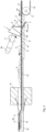
- the production line for the irrigation hose with the subsequent processing stage is shown in figure 3 .
- the direction of transport is from right to left.
- Emitters E are delivered from a conveyor belt 10 to the feeding device and its rotating conveyor screw 1.
- the drippers conveyor belt 10 does not pass under the rotating screw conveyor 1 but extends to the edge of the drippers guide rail 8 which is below the rotating screw conveyor 1.
- the emitters E leave the conveyor belt 10 at the idler pulley 11 and are from there pushed onto the guide rail 8, which abuts to idler pulley 11 and aligns with the conveyor belt 10 in transport direction.
- An emitter E arriving at the guide rail 8 is then briefly stopped and retarded by the protrusion 5 engaging with its water basin recess 9 so that gap d2 is created between it and its immediately preceding emitter.
- the leading tip 6 of the helix enters into the gap d2 and forwards and accelerates the emitter.
- the main purpose of the rotating screw conveyor 1 is to exactly position and singularize the drippers E on their way to the subsequent processing stage and also to push the drippers forward with controlled and steady speed.
- the protrusion 5 instantly holds the drippers, which are conveyed by the dripper's conveyor belt towards the rotating conical screw conveyor 1.
- additional forward thrust of the dripper E2 by means of compressed air and in conjunction with the position of the protrusion 5 and the leading tip 6 of the helix 4, a large enough gap between two consecutive drippers is created where the leading tip 6 of the helix 4 can enter.
- the helix 4 linearly forwards the dripper E2 without touching the dripper E3 (see figure 1 ) ensuring smooth, accurate, stable and non-vibrating feeding of the drippers.
- the emitters E move forward on guide rail 8, designed to transport a specific product of a specific shape, i.e. the drippers E, pushed by the helix 4 of the rotating screw conveyor 1. Every complete turn of the rotating screw conveyor 1 corresponds to a forward movement equal to the length of one dripper E.
- stinger 12 In transport direction behind the guide rail 8 follows a further guide rail 12 termed the "stinger". Towards its far end 13, the stinger 12 is slightly offset and bent up. The stinger 12 passes through an extruder die head 14, from which a pipe 15 is extruded, and ends just after the point where the inner surfaces of the extruded pipe 15 become parallel to each other.
- the extrusion of plastics is a manufacturing process in which raw plastic material is molten and formed into a continuous profile such as a pipe, hose, tube or the like.
- An extruder has the function of heating the raw plastic material to molten state and then force it through a die, which shapes the material into a product of the desired shape.
- the extruder has a rotating extruder screw, which forces the plastic beads forward into a heated barrel. The plastic beads gradually melt as they are pushed through the barrel. Extra heat is contributed by the intense pressure and friction taking place inside the barrel.
- the molten plastic leaves the screw and travels through a screen pack breaker plate which removes any contaminants in the melt and also converts a rotational movement of the molten plastic into axial movement.
- molten plastic enters the extrusion die head 14.
- the purpose of the extrusion die head 14 is to form the molten resin into its final or near-final shape prior to quenching.
- the die is what gives the final product its profile and is designed so that the molten plastic evenly flows from a cylindrical profile, to the product's profile shape.
- the melt flow channel is usually in the form of circular supply orifice.
- the extrusion die converts this rod of resin into an annular (tubular) shape to form a pipe.
- the size of the pipe - diameter and thickness - are formed by different size tooling types - mandrel and die - of the cross head.
- a crosshead extrusion die 14 shown as a simple schematic by longitudinal sectional view the in the embodiment of figure 3 , has an operational centerline that is perpendicular to the extruder screw axis. This is used in the embodiment to feed the drippers E by the stinger 12 from behind the crosshead 14 through an opening along its centerline directly into the tube 15 as it is extruded from the crosshead die. The stinger bending up at its end 13 directs the emitters towards the inner wall of the pipe 15.
- the emitter sticks there and the offset end 13 of the stinger 12, which guides and holds the emitter against the inside wall of the tube 15 as it is tensioned away from the crosshead die while the material begins to solidify, makes sure the emitter is firmly attached to where it first contacts and sticks to the inside wall of the tube 15.
- drip line tube 15 One of the basic requirements for the production of drip line tube 15 is the controlled placement and adhesion of the drippers E on the inner wall of the tube 15, to the desired distance between them, i.e. the drippers spacing d3.
- the creation of the desired dripper spacing d3 results from the properly controlled steady feeding speed of the emitter E as they are delivered by the conveyor screw 1 of the drippers feeder and the extrusion speed of the tube 15.
Landscapes
- Engineering & Computer Science (AREA)
- Mechanical Engineering (AREA)
- Life Sciences & Earth Sciences (AREA)
- Manufacturing & Machinery (AREA)
- Soil Sciences (AREA)
- Water Supply & Treatment (AREA)
- Environmental Sciences (AREA)
- Extrusion Moulding Of Plastics Or The Like (AREA)
Description
- The present invention relates to a feeding device for use in a production line, in particular to a dripper feeding device for feeding drippers to a dripping pipe production line, in which the feeding device has a rotating body with a helical transport structure at its circumferential surface and wherein the helical transport structure is designed for feeding individual components in a transport direction to a subsequent processing machine.
- A dripper feeding device, which feeds drippers to a dripping pipe production line is known from
WO 2012/164564 A1 . The dripper feeding device rotates about a rotation axis and comprises a cylindrical feeder body and at least one helix made on the cylindrical face of the feeder body. The helix can be a protruding helix or a submerged helix. A rotation means rotates said dripper feeding device at a controlled speed. - The described feeding device may become unstable and inaccurate at higher feeding speed. In particular, when the leading tip of the helix of the cylindrical feeding device enters between two consecutive drippers, the leading tip of the helix pushes smoothly the first dripper towards the production direction but at the same time pushes the subsequent drippers that follow in a row on the corresponding conveying rail backwards, i.e. against to the pipe production direction. This causes feeding instability of the drippers.
- It is therefore an object of the present invention to provide a production line for a drip irrigation tube with a feeding device for feeding drippers to a dripping pipe production line, which allows more stable feeding of the drippers to a subsequent processing stage and thus enables higher production speed and/or feeding accuracy and which is less prone to malfunction.
- These and other objects that appear below are achieved by a production line for a drip irrigation tube with a feeding device in accordance with
claim 1. Advantageous embodiments are described in the dependent claims. - In particular, and in accordance with the present invention, the production line for a drip irrigation tube comprises a feeding device arranged for feeding drippers at a controlled speed to an extruder die head arranged for extruding said tube from molten raw plastic material, the feeding device comprising a rotating body with a helical transport structure at its circumferential surface, an outer diameter of which defines a conical form of said rotating body having an aperture angle. The rotating body is arranged such that its rotational axis is inclined with respect to the transport direction by half its aperture angle.
- A particular advantage of this is that the conical form of the conveyor helix continuously increases the feeding speed of the dripper during rotation of the rotating body from when the dripper first contacts with the helix until the helix delivers the dripper to the subsequent processing stage due to the increasing diameter of the conical helix. Consequently, the helix, which acts as kind of a screw conveyor, receives and linearly moves the dripper forward towards the subsequent processing stage at a lower initial speed.
- According to one aspect of the invention, the rotating body of the feeding device comprises at its circumferential surface a protrusion located ahead of a leading end of the helical transport structure. The protrusion is arranged to temporarily engage by the rotation of the rotating body with a recess in a surface of said drippers to be transported and to retard while being engaged said dripper from being received by said helical transport structure.
- The purpose of the protrusion is to instantly hold the drippers, which are conveyed for instance by a conveyor belt to the feeding device. The protrusion thus creates a large enough gap between two consecutive drippers that the leading tip of the helix can catch between the two consecutive drippers. The helix forwards the received dripper in linear direction without making contact with the subsequent dripper. This leads to a smooth, accurate, stable and non-vibrating operation of feeding of drippers.
- In contrast, system described in the aforementioned
application WO 2012/164564 A1 becomes unstable and inaccurate. When the leading tip of the helix of the cylindrical feeding device enters between two consecutive components, it slightly pushes the first component in production direction and at the same time pushes the subsequent and all following components backwards in counter direction, thus causing feeding instability of the components. In contrast to the current invention, the cylindrical feeding device in the prior art does not create a gap between consecutive components for a smooth engagement of the components with the transport helix. - In an embodiment, the distance in transport direction between the protrusion and the leading end of the helical transport structure can be chosen in dependence of the location of the recess of said drippers. The rotating body is thus perfectly matched to the design of the drippers it is designed to operate with, which leads to a perfectly smooth and accurate feeding of such drippers.
- The protrusion may have a circumferential length with no pitch or at least a smaller pitch than the helical transport structure, so that a dripper while being engaged with said protrusion, as the rotating body rotates, experiences a lower feed speed in transport direction than a dripper received by the helical transport structure.
- The helical transport structure can be chosen from is either a protruding ridge or a recessed notch, i.e. can be either protruded or submerged with respect to the circumferential surface of the rotating body.
- In a particular embodiment, the helical transport structure can have only a single helical loop. The helical transport structure may thus deliver with high precision one component per rotation to the subsequent processing stage.
- Preferably, the helical transport structure has a pitch which corresponds to a lateral dimension of the dripper, i.e. its length, being oriented in the transport direction. The helix will thus forward the dripper in transport direction by one dripper length per rotation. Moreover, the dripper will be safely and accurately received between the leading and the trailing edge of the helix.
- The feeding device in the preferred embodiment is arranged for feeding the drippers to an inside of the pipe as it is extruded by said extruder, so that the drippers will make contact with the still soft and sticky material of the tube and will easily stick to the inside wall of the tube as it makes contact there.
- The feeding device within the production line according to the present invention may contain a drive unit which rotates the rotating body during operation at a speed of up to 2000 RPM or even higher. The actual rotational speed depends on the desired distance of the drippers inside the pipe - the higher the rotational speed of the feeding device, the shorter the distance between drippers inside the pipe. A typical minimum spacing required today by farmers is in the range of 10 cm.
- The feeding device within the production line according to the invention may further have a compressed air supply coupled with the rotating body to support feeding by pulses of compressed air in synchronism with the angular position of said rotating body. The compressed air supply can be located, aligned, and controlled in such a way as to facilitate feeding. Control of the compressed air supply can be achieved by mechanical means which synchronize with the functions of other parts of the feeding system to ensure smooth dripper feeding.
- The feeding device within the production line according to the invention may further comprising a support rail and/or a conveyor belt oriented in the transport direction along which the components are moved by the helical transport structure in operation of said rotating body.
- Other aspects, features, and advantages will be disclosed in the following description of embodiments.
- Embodiments of the present invention will be described below with reference to the accompanying drawings, in which
- fig. 1
- shows side view of a feeding device in accordance with the present invention;
- fig. 2
- shows a front view of the feeding device of
fig. 1 looking into transport direction; and - fig. 3
- the feeding device of
figure 1 and a subsequent processing stage including an extruder die head. - The embodiment described below relates to a production line for a drip irrigation pipe or hose. Drip irrigation is an irrigation method that delivers water in small doses directly to the roots of plants, either onto the soil surface or directly onto the root zone of crop plants. Thus, wasted water due to run-off, evaporation, or the like is substantially reduced. An emitter, which is also termed a "dripper", is used to transfer water from a pipe or hose to the area that is to be irrigated. An emitting pipe or hose is a type of drip irrigation tubing with emitters pre-installed at the factory with specific distance and flow per hour as per crop distance.
- An irrigation hose of the type described below has emitters attached to the inside wall with a defined spacing between the individual emitters. Perforations are drilled into the hose wall close to a water basin of the emitters, respectively, so that water can be delivered in small doses, depending on the design of the emitter. Typical emitter flow rates are from 0.6 to 16 liters per hour.
-
Figure 1 shows a feeding device for the emitters. The device contains aconical body 1, which has the form of a truncated cone. Theconical body 1 has ashaft 2, which is driven by a drive means 2a such as a motor so that in operation, thebody 1 rotates about itslongitudinal axis 3 at a controlled speed. At its circumferential surface, thebody 1 has ahelical transport structure 4, such as a protruding helix. - The
conical body 1 is installed above aguide rail 8 such that therotational axis 3 of theconical body 1 is inclined by half its aperture angle, i.e. such that its lateral surface where it facesguide rail 8 is substantially parallel to the latter. Thetransport structure 4 operates similar to a conveyor screw. Emitters are moved along the guide rail by the rotation of thebody 1 through the forward thrust of thehelix 4. The pitch of thehelix 4 corresponds substantially to the length of an emitter so that the emitter, as it is received by the helix is moved forward by one emitter length per full 360° rotation of thebody 1. - It has to be noted in this regard that it is not essential that the
body 1 has the form of a truncated cone as shown in the embodiment and that the invention is not limited to the specific form shown. Instead, it would equally be possible that theinside body 1 has a straight non-conical form for instance and that the height of the helical ridge extending in radial direction from the surface of therotating body 1 and forming thehelix 4 increases in the transport direction. In other words, the outer diameter of saidhelical transport structure 4 follows a conical form - either through the conical form of the rotating body itself or by an increasing ridge height of thehelix 4 extending from therotating body 1. - Coming back to
figure 1 , four emitters E1-E4 are shown in the figure on theguide rail 8. The direction of transport is from right to left as indicated by an arrow. Each of the emitter E1-E4 has in about the middle of its upper surface side asmall recess 9, which serves as a water basin. - As can be seen in
figure 2 , theconical body 1 has at its circumferential surface aprotrusion 5 located ahead of aleading tip 6 of thehelix 4. The distance d1 betweenprotrusion 5 and thetip end 6 of thehelix 4 corresponds to the distance between the leading edge of an emitter E1-E4 and itsbasin 9, more particularly to the trailing edge of thebasin 9. Theprotrusion 5 is therefore located such that by the rotation of theconical body 1 theprotrusion 5 engages with thewater basin 9 of an emitter - such as emitter E3 shown infigure 1 . Contrary to thehelix 4, the protrusion has no pitch (or an at least much lower pitch). Therefore, as long as the protrusion is engaged with thewater basin 9 of an emitter E3, this emitter does not experience a forward thrust but is temporarily retarded. This small retardation creates a gap between the preceding emitter E2 and the emitter theprotrusion 5 currently engages with. The gap is large enough that the leadingtip 6 of thehelix 4 can enter between the two emitters E3, E2 without even contacting them. - Once the
protrusion 5 disengages with thewater basin 9 of emitter E3, emitter E3 will enter thehelix 4 and will then be linearly forwarded byhelix 4. This forward movement is supported by a pulse of compressed air, which is blown throughchannel 7 from a nozzle arranged belowguide rail 8. - The compressed air is provided by pulses and is sprayed within a mechanically adjustable time period in order to push forward the dripper E2 ensuring that it is constantly touching the
rotating helix 4. The purpose of the compressed air is to create the gap d2 between two consecutive drippers E2, E3. - The truncated cone shape of the rotating body facilitates smooth engagement or "grabbing" of the drippers and a linear movement thereof towards the subsequent processing stage in the direction of transport.
- When the
truncated cone body 1 rotates about itslongitudinal axis 3, thehelix 4 receives and moves a dripper E3 from the side with the small base of thetruncated cone body 1 towards the side with the large base. The speed of the grabbed dripper increases continuously during rotation of thetruncated cone 1 due to the diameter of thetruncated cone 1 increasing in transport direction. Consequently, thehelix 4, which acts as a feeding helical thread, receives and linearly moves forward the dripper towards the pipe production direction at an initial lower speed, which contributes to a smoother and more stable transport of the drippers E. - The production line for the irrigation hose with the subsequent processing stage is shown in
figure 3 . The direction of transport is from right to left. Emitters E are delivered from aconveyor belt 10 to the feeding device and itsrotating conveyor screw 1. Thedrippers conveyor belt 10 does not pass under therotating screw conveyor 1 but extends to the edge of thedrippers guide rail 8 which is below therotating screw conveyor 1. The emitters E leave theconveyor belt 10 at theidler pulley 11 and are from there pushed onto theguide rail 8, which abuts toidler pulley 11 and aligns with theconveyor belt 10 in transport direction. - An emitter E arriving at the
guide rail 8 is then briefly stopped and retarded by theprotrusion 5 engaging with itswater basin recess 9 so that gap d2 is created between it and its immediately preceding emitter. By the rotation of theconveyor screw 1, the leadingtip 6 of the helix enters into the gap d2 and forwards and accelerates the emitter. - The main purpose of the
rotating screw conveyor 1 is to exactly position and singularize the drippers E on their way to the subsequent processing stage and also to push the drippers forward with controlled and steady speed. Theprotrusion 5 instantly holds the drippers, which are conveyed by the dripper's conveyor belt towards the rotatingconical screw conveyor 1. With additional forward thrust of the dripper E2, by means of compressed air and in conjunction with the position of theprotrusion 5 and the leadingtip 6 of thehelix 4, a large enough gap between two consecutive drippers is created where the leadingtip 6 of thehelix 4 can enter. Thus, thehelix 4 linearly forwards the dripper E2 without touching the dripper E3 (seefigure 1 ) ensuring smooth, accurate, stable and non-vibrating feeding of the drippers. - Behind the
rotating screw conveyor 1 the emitters E move forward onguide rail 8, designed to transport a specific product of a specific shape, i.e. the drippers E, pushed by thehelix 4 of therotating screw conveyor 1. Every complete turn of therotating screw conveyor 1 corresponds to a forward movement equal to the length of one dripper E. - In transport direction behind the
guide rail 8 follows afurther guide rail 12 termed the "stinger". Towards itsfar end 13, thestinger 12 is slightly offset and bent up. Thestinger 12 passes through anextruder die head 14, from which apipe 15 is extruded, and ends just after the point where the inner surfaces of the extrudedpipe 15 become parallel to each other. - The extrusion of plastics is a manufacturing process in which raw plastic material is molten and formed into a continuous profile such as a pipe, hose, tube or the like. An extruder has the function of heating the raw plastic material to molten state and then force it through a die, which shapes the material into a product of the desired shape. The extruder has a rotating extruder screw, which forces the plastic beads forward into a heated barrel. The plastic beads gradually melt as they are pushed through the barrel. Extra heat is contributed by the intense pressure and friction taking place inside the barrel.
- At the front of the barrel, the molten plastic leaves the screw and travels through a screen pack breaker plate which removes any contaminants in the melt and also converts a rotational movement of the molten plastic into axial movement. After passing through the breaker plate, molten plastic enters the extrusion die
head 14. The purpose of the extrusion diehead 14 is to form the molten resin into its final or near-final shape prior to quenching. The die is what gives the final product its profile and is designed so that the molten plastic evenly flows from a cylindrical profile, to the product's profile shape. When resin enters the extrusion die from the extruder and screen changer, the melt flow channel is usually in the form of circular supply orifice. The extrusion die converts this rod of resin into an annular (tubular) shape to form a pipe. The size of the pipe - diameter and thickness - are formed by different size tooling types - mandrel and die - of the cross head. - A crosshead extrusion die 14, shown as a simple schematic by longitudinal sectional view the in the embodiment of
figure 3 , has an operational centerline that is perpendicular to the extruder screw axis. This is used in the embodiment to feed the drippers E by thestinger 12 from behind thecrosshead 14 through an opening along its centerline directly into thetube 15 as it is extruded from the crosshead die. The stinger bending up at itsend 13 directs the emitters towards the inner wall of thepipe 15. Since the material of thetube 15 as it leaves the crosshead die 14 is still viscid and sticky, the emitter sticks there and the offsetend 13 of thestinger 12, which guides and holds the emitter against the inside wall of thetube 15 as it is tensioned away from the crosshead die while the material begins to solidify, makes sure the emitter is firmly attached to where it first contacts and sticks to the inside wall of thetube 15. - One of the basic requirements for the production of
drip line tube 15 is the controlled placement and adhesion of the drippers E on the inner wall of thetube 15, to the desired distance between them, i.e. the drippers spacing d3. The creation of the desired dripper spacing d3 results from the properly controlled steady feeding speed of the emitter E as they are delivered by theconveyor screw 1 of the drippers feeder and the extrusion speed of thetube 15.
Claims (10)
- A production line for a drip irrigation tube comprising a feeding device arranged for feeding drippers (E, E1-E4) at a controlled speed to an extruder die head (14) arranged for extruding said tube (15) from molten raw plastic material, the feeding device comprising a rotating body (1) with a helical transport structure (4) at its circumferential surface, the helical transport structure (4) being designed for feeding individual drippers (E, E1-E4) in a transport direction to an inside of said tube (15) as it is extruded by said extruder die head (14),
characterized in that
an outer diameter of said helical transport structure (4) defines a conical form of said rotating body (1) having an aperture angle and that a rotational axis (3) of said rotating body (1) is inclined with respect to the transport direction by half the aperture angle. - A production line according to claim 1, wherein the rotating body (1) of the feeding device comprises at its circumferential surface a protrusion (5) located ahead of a leading end (6) of the helical transport structure (4), which protrusion (5) is arranged to temporarily engage by the rotation of the rotating body (1) with a recess (9) in a surface of said drippers (E, E1-E4) to be transported and to retard while being engaged said dripper (E, E1-E4) from being received by said helical transport structure (4).
- A production line according to claim 2, wherein said protrusion (5) is located such that the distance (d1) in transport direction between the protrusion (5) and the leading end (6) of the helical transport structure (4) is chosen in dependence of the location of the recess (9) of said drippers (E, E1-E4).
- A production line according to claim 2 or 3, wherein said protrusion (5) has a circumferential length with no pitch or at least a smaller pitch than the helical transport structure (4), so that a dripper (E, E1-E4) while being engaged with said protrusion (5), as the rotating body (1) rotates, experiences a lower forward thrust in transport direction than a dripper (E, E1-E4) received by the helical transport structure (4).
- A production line according to any of the preceding claims, wherein said helical transport structure (4) is either a protruding ridge or a recessed notch.
- A production line according to any of the preceding claims, wherein said helical transport structure (4) comprises only a single helical loop.
- A production line according to any of the preceding claims, wherein said helical transport structure (4) has a pitch which corresponds to a lateral dimension of said dripper (E, E1-E4) being oriented in the transport direction
- A production line according to any of the preceding claims, wherein the feeding device further comprises a compressed air supply (7) controlled to support feeding by pulses of compressed air in synchronism with the angular position of said rotating body (1).
- A production line according to any of the preceding claims, wherein the feeding device further comprises a support rail (8) oriented in the transport direction along which the drippers (E, E1-E4) are moved by the helical transport structure (4) at operation of said rotating body (1).
- A production line according to any of the preceding claims, wherein said extruder die head (14) is of a crosshead type and wherein the production line comprises a guide rail (12) extending through the extruder die head (14) and into the extruded tube as it is tensioned away from the extruder die head (14).
Priority Applications (2)
| Application Number | Priority Date | Filing Date | Title |
|---|---|---|---|
| ES17189573T ES2957884T3 (en) | 2017-09-06 | 2017-09-06 | Production line for a drip irrigation tube |
| EP17189573.3A EP3453513B1 (en) | 2017-09-06 | 2017-09-06 | Production line for a drip irrigation tube |
Applications Claiming Priority (1)
| Application Number | Priority Date | Filing Date | Title |
|---|---|---|---|
| EP17189573.3A EP3453513B1 (en) | 2017-09-06 | 2017-09-06 | Production line for a drip irrigation tube |
Publications (3)
| Publication Number | Publication Date |
|---|---|
| EP3453513A1 EP3453513A1 (en) | 2019-03-13 |
| EP3453513C0 EP3453513C0 (en) | 2023-08-30 |
| EP3453513B1 true EP3453513B1 (en) | 2023-08-30 |
Family
ID=59846380
Family Applications (1)
| Application Number | Title | Priority Date | Filing Date |
|---|---|---|---|
| EP17189573.3A Active EP3453513B1 (en) | 2017-09-06 | 2017-09-06 | Production line for a drip irrigation tube |
Country Status (2)
| Country | Link |
|---|---|
| EP (1) | EP3453513B1 (en) |
| ES (1) | ES2957884T3 (en) |
Families Citing this family (2)
| Publication number | Priority date | Publication date | Assignee | Title |
|---|---|---|---|---|
| CN111657102A (en) * | 2020-05-21 | 2020-09-15 | 胡伟峰 | Anti-blocking water-saving drip irrigation system and irrigation method thereof |
| CN119841020B (en) * | 2025-03-24 | 2025-07-18 | 山西恒荣药业有限公司 | Conveying device with dustproof and anti-blocking functions for processing traditional Chinese medicine decoction pieces |
Family Cites Families (8)
| Publication number | Priority date | Publication date | Assignee | Title |
|---|---|---|---|---|
| GB108382A (en) * | 1916-09-11 | 1917-08-09 | Norman Mckenzie | Improved Apparatus for Elevating, Sacking and Weighing Grain and other materials. |
| NL37895C (en) * | 1933-11-17 | 1936-04-15 | ||
| US2375965A (en) * | 1943-11-25 | 1945-05-15 | Alfred C Turtle | Portable power-driven conveyer |
| US2792098A (en) * | 1953-01-05 | 1957-05-14 | Fritz W Teske | Device for picking up and conveying material |
| GB1320958A (en) * | 1970-11-09 | 1973-06-20 | Johnson Stephens Ltd Gordon | Poultry processing machine and method |
| US4036411A (en) * | 1975-09-26 | 1977-07-19 | Sos Consolidated, Inc. | Low profile auger and hopper assembly |
| DE19805618A1 (en) * | 1998-02-12 | 1999-08-26 | Meinfelder | Helical feed assembly produces a steady feed of single components |
| US20140090229A1 (en) | 2011-06-02 | 2014-04-03 | Shlomo Bloom | System and method for high speed feeding of dripper to irrigation pipe in production |
-
2017
- 2017-09-06 ES ES17189573T patent/ES2957884T3/en active Active
- 2017-09-06 EP EP17189573.3A patent/EP3453513B1/en active Active
Also Published As
| Publication number | Publication date |
|---|---|
| EP3453513A1 (en) | 2019-03-13 |
| ES2957884T3 (en) | 2024-01-29 |
| EP3453513C0 (en) | 2023-08-30 |
Similar Documents
| Publication | Publication Date | Title |
|---|---|---|
| US4826423A (en) | Construction of thermoplastic tubes with tubular ribs by helical winding upon a mandrel | |
| EP3453513A1 (en) | Feeding device for use in a production line | |
| RU2415565C2 (en) | Device to feed and install droppers in watering pipeline of trickle irrigation | |
| US20060162867A1 (en) | Device for continuously producing drip irrigation tubes | |
| JPS6052924B2 (en) | Extrusion method and two-stage single screw extrusion device | |
| US3090992A (en) | Apparatus for the manufacture of filaments or other shaped structures from thermoplasts | |
| US20260077559A1 (en) | Filament feeding devices and methods for fused deposition modeling (fdm) numerically controlled 3d printers | |
| JP2010105296A (en) | Device and method of adjusting degree of kneading | |
| US12257776B2 (en) | Pellet extruder for 3D printing | |
| US7014447B2 (en) | Extruder for welding plastic components | |
| CN107263839A (en) | Apparatus and method for continuously extruding the tubing with different materials | |
| KR20020008081A (en) | Unitary spray nozzle | |
| CN113927829A (en) | Plasticizing injection molding mechanism of injection molding machine and using method thereof | |
| EP3826826B1 (en) | Method and apparatus for managing ooze from a print nozzle | |
| CN205395090U (en) | Plastic extruder | |
| CN104608362B (en) | plastic extruder | |
| JP5941727B2 (en) | Screw, plasticizing device, injection device, injection molding device, extruder, and method for producing molded product | |
| CN111113848A (en) | Rotary die device for metal-coated garden tube | |
| KR101170605B1 (en) | Apparatus and method for preparing raindrop hose | |
| US5255434A (en) | Process and apparatus for the continuous production of an irrigating tube | |
| EP3453508A1 (en) | Extruder feeding assembly and extruder apparatus incorporating it | |
| KR101153429B1 (en) | Apparatus and method for preparing raindrop hose | |
| EP3674070B1 (en) | Rubber extrusion device and method for manufacturing rubber extruded object | |
| KR20180094719A (en) | Apparatus | |
| JP2927745B2 (en) | Plasticizing and kneading equipment |
Legal Events
| Date | Code | Title | Description |
|---|---|---|---|
| PUAI | Public reference made under article 153(3) epc to a published international application that has entered the european phase |
Free format text: ORIGINAL CODE: 0009012 |
|
| STAA | Information on the status of an ep patent application or granted ep patent |
Free format text: STATUS: THE APPLICATION HAS BEEN PUBLISHED |
|
| AK | Designated contracting states |
Kind code of ref document: A1 Designated state(s): AL AT BE BG CH CY CZ DE DK EE ES FI FR GB GR HR HU IE IS IT LI LT LU LV MC MK MT NL NO PL PT RO RS SE SI SK SM TR |
|
| AX | Request for extension of the european patent |
Extension state: BA ME |
|
| STAA | Information on the status of an ep patent application or granted ep patent |
Free format text: STATUS: REQUEST FOR EXAMINATION WAS MADE |
|
| 17P | Request for examination filed |
Effective date: 20190909 |
|
| RBV | Designated contracting states (corrected) |
Designated state(s): AL AT BE BG CH CY CZ DE DK EE ES FI FR GB GR HR HU IE IS IT LI LT LU LV MC MK MT NL NO PL PT RO RS SE SI SK SM TR |
|
| STAA | Information on the status of an ep patent application or granted ep patent |
Free format text: STATUS: EXAMINATION IS IN PROGRESS |
|
| 17Q | First examination report despatched |
Effective date: 20210601 |
|
| RIN1 | Information on inventor provided before grant (corrected) |
Inventor name: BOLINIS, CHRISTOS |
|
| REG | Reference to a national code |
Ref country code: DE Ref legal event code: R079 Free format text: PREVIOUS MAIN CLASS: B29C0047100000 Ipc: B29C0048285000 Ref country code: DE Ref legal event code: R079 Ref document number: 602017073323 Country of ref document: DE Free format text: PREVIOUS MAIN CLASS: B29C0047100000 Ipc: B29C0048285000 |
|
| GRAP | Despatch of communication of intention to grant a patent |
Free format text: ORIGINAL CODE: EPIDOSNIGR1 |
|
| STAA | Information on the status of an ep patent application or granted ep patent |
Free format text: STATUS: GRANT OF PATENT IS INTENDED |
|
| RIC1 | Information provided on ipc code assigned before grant |
Ipc: B29C 48/34 20190101ALN20230421BHEP Ipc: A01G 25/02 20060101ALI20230421BHEP Ipc: B65G 47/28 20060101ALI20230421BHEP Ipc: B29C 48/155 20190101ALI20230421BHEP Ipc: B29C 48/09 20190101ALI20230421BHEP Ipc: B29C 48/285 20190101AFI20230421BHEP |
|
| INTG | Intention to grant announced |
Effective date: 20230512 |
|
| GRAS | Grant fee paid |
Free format text: ORIGINAL CODE: EPIDOSNIGR3 |
|
| GRAA | (expected) grant |
Free format text: ORIGINAL CODE: 0009210 |
|
| STAA | Information on the status of an ep patent application or granted ep patent |
Free format text: STATUS: THE PATENT HAS BEEN GRANTED |
|
| AK | Designated contracting states |
Kind code of ref document: B1 Designated state(s): AL AT BE BG CH CY CZ DE DK EE ES FI FR GB GR HR HU IE IS IT LI LT LU LV MC MK MT NL NO PL PT RO RS SE SI SK SM TR |
|
| REG | Reference to a national code |
Ref country code: GB Ref legal event code: FG4D |
|
| REG | Reference to a national code |
Ref country code: CH Ref legal event code: EP |
|
| REG | Reference to a national code |
Ref country code: DE Ref legal event code: R096 Ref document number: 602017073323 Country of ref document: DE |
|
| REG | Reference to a national code |
Ref country code: IE Ref legal event code: FG4D |
|
| U01 | Request for unitary effect filed |
Effective date: 20230905 |
|
| U07 | Unitary effect registered |
Designated state(s): AT BE BG DE DK EE FI FR IT LT LU LV MT NL PT SE SI Effective date: 20230912 |
|
| U20 | Renewal fee for the european patent with unitary effect paid |
Year of fee payment: 7 Effective date: 20230922 |
|
| PG25 | Lapsed in a contracting state [announced via postgrant information from national office to epo] |
Ref country code: GR Free format text: LAPSE BECAUSE OF FAILURE TO SUBMIT A TRANSLATION OF THE DESCRIPTION OR TO PAY THE FEE WITHIN THE PRESCRIBED TIME-LIMIT Effective date: 20231201 |
|
| PG25 | Lapsed in a contracting state [announced via postgrant information from national office to epo] |
Ref country code: IS Free format text: LAPSE BECAUSE OF FAILURE TO SUBMIT A TRANSLATION OF THE DESCRIPTION OR TO PAY THE FEE WITHIN THE PRESCRIBED TIME-LIMIT Effective date: 20231230 |
|
| REG | Reference to a national code |
Ref country code: ES Ref legal event code: FG2A Ref document number: 2957884 Country of ref document: ES Kind code of ref document: T3 Effective date: 20240129 |
|
| PG25 | Lapsed in a contracting state [announced via postgrant information from national office to epo] |
Ref country code: RS Free format text: LAPSE BECAUSE OF FAILURE TO SUBMIT A TRANSLATION OF THE DESCRIPTION OR TO PAY THE FEE WITHIN THE PRESCRIBED TIME-LIMIT Effective date: 20230830 Ref country code: NO Free format text: LAPSE BECAUSE OF FAILURE TO SUBMIT A TRANSLATION OF THE DESCRIPTION OR TO PAY THE FEE WITHIN THE PRESCRIBED TIME-LIMIT Effective date: 20231130 Ref country code: IS Free format text: LAPSE BECAUSE OF FAILURE TO SUBMIT A TRANSLATION OF THE DESCRIPTION OR TO PAY THE FEE WITHIN THE PRESCRIBED TIME-LIMIT Effective date: 20231230 Ref country code: HR Free format text: LAPSE BECAUSE OF FAILURE TO SUBMIT A TRANSLATION OF THE DESCRIPTION OR TO PAY THE FEE WITHIN THE PRESCRIBED TIME-LIMIT Effective date: 20230830 Ref country code: GR Free format text: LAPSE BECAUSE OF FAILURE TO SUBMIT A TRANSLATION OF THE DESCRIPTION OR TO PAY THE FEE WITHIN THE PRESCRIBED TIME-LIMIT Effective date: 20231201 |
|
| PG25 | Lapsed in a contracting state [announced via postgrant information from national office to epo] |
Ref country code: PL Free format text: LAPSE BECAUSE OF FAILURE TO SUBMIT A TRANSLATION OF THE DESCRIPTION OR TO PAY THE FEE WITHIN THE PRESCRIBED TIME-LIMIT Effective date: 20230830 |
|
| PG25 | Lapsed in a contracting state [announced via postgrant information from national office to epo] |
Ref country code: SM Free format text: LAPSE BECAUSE OF FAILURE TO SUBMIT A TRANSLATION OF THE DESCRIPTION OR TO PAY THE FEE WITHIN THE PRESCRIBED TIME-LIMIT Effective date: 20230830 Ref country code: RO Free format text: LAPSE BECAUSE OF FAILURE TO SUBMIT A TRANSLATION OF THE DESCRIPTION OR TO PAY THE FEE WITHIN THE PRESCRIBED TIME-LIMIT Effective date: 20230830 Ref country code: CZ Free format text: LAPSE BECAUSE OF FAILURE TO SUBMIT A TRANSLATION OF THE DESCRIPTION OR TO PAY THE FEE WITHIN THE PRESCRIBED TIME-LIMIT Effective date: 20230830 Ref country code: SK Free format text: LAPSE BECAUSE OF FAILURE TO SUBMIT A TRANSLATION OF THE DESCRIPTION OR TO PAY THE FEE WITHIN THE PRESCRIBED TIME-LIMIT Effective date: 20230830 |
|
| PG25 | Lapsed in a contracting state [announced via postgrant information from national office to epo] |
Ref country code: MC Free format text: LAPSE BECAUSE OF FAILURE TO SUBMIT A TRANSLATION OF THE DESCRIPTION OR TO PAY THE FEE WITHIN THE PRESCRIBED TIME-LIMIT Effective date: 20230830 |
|
| REG | Reference to a national code |
Ref country code: DE Ref legal event code: R097 Ref document number: 602017073323 Country of ref document: DE |
|
| REG | Reference to a national code |
Ref country code: IE Ref legal event code: MM4A |
|
| PG25 | Lapsed in a contracting state [announced via postgrant information from national office to epo] |
Ref country code: IE Free format text: LAPSE BECAUSE OF NON-PAYMENT OF DUE FEES Effective date: 20230906 |
|
| PLBE | No opposition filed within time limit |
Free format text: ORIGINAL CODE: 0009261 |
|
| STAA | Information on the status of an ep patent application or granted ep patent |
Free format text: STATUS: NO OPPOSITION FILED WITHIN TIME LIMIT |
|
| GBPC | Gb: european patent ceased through non-payment of renewal fee |
Effective date: 20231130 |
|
| PG25 | Lapsed in a contracting state [announced via postgrant information from national office to epo] |
Ref country code: IE Free format text: LAPSE BECAUSE OF NON-PAYMENT OF DUE FEES Effective date: 20230906 |
|
| 26N | No opposition filed |
Effective date: 20240603 |
|
| U20 | Renewal fee for the european patent with unitary effect paid |
Year of fee payment: 8 Effective date: 20240712 |
|
| PG25 | Lapsed in a contracting state [announced via postgrant information from national office to epo] |
Ref country code: GB Free format text: LAPSE BECAUSE OF NON-PAYMENT OF DUE FEES Effective date: 20231130 |
|
| PG25 | Lapsed in a contracting state [announced via postgrant information from national office to epo] |
Ref country code: GB Free format text: LAPSE BECAUSE OF NON-PAYMENT OF DUE FEES Effective date: 20231130 |
|
| PG25 | Lapsed in a contracting state [announced via postgrant information from national office to epo] |
Ref country code: CY Free format text: LAPSE BECAUSE OF FAILURE TO SUBMIT A TRANSLATION OF THE DESCRIPTION OR TO PAY THE FEE WITHIN THE PRESCRIBED TIME-LIMIT; INVALID AB INITIO Effective date: 20170906 |
|
| PG25 | Lapsed in a contracting state [announced via postgrant information from national office to epo] |
Ref country code: HU Free format text: LAPSE BECAUSE OF FAILURE TO SUBMIT A TRANSLATION OF THE DESCRIPTION OR TO PAY THE FEE WITHIN THE PRESCRIBED TIME-LIMIT; INVALID AB INITIO Effective date: 20170906 |
|
| U20 | Renewal fee for the european patent with unitary effect paid |
Year of fee payment: 9 Effective date: 20250715 |
|
| REG | Reference to a national code |
Ref country code: CH Ref legal event code: U11 Free format text: ST27 STATUS EVENT CODE: U-0-0-U10-U11 (AS PROVIDED BY THE NATIONAL OFFICE) Effective date: 20251001 |
|
| PGFP | Annual fee paid to national office [announced via postgrant information from national office to epo] |
Ref country code: TR Payment date: 20250902 Year of fee payment: 9 |
|
| PGFP | Annual fee paid to national office [announced via postgrant information from national office to epo] |
Ref country code: CH Payment date: 20251001 Year of fee payment: 9 |
|
| PGFP | Annual fee paid to national office [announced via postgrant information from national office to epo] |
Ref country code: ES Payment date: 20251020 Year of fee payment: 9 |