EP3453482A1 - Laser welding jig assembly - Google Patents
Laser welding jig assembly Download PDFInfo
- Publication number
- EP3453482A1 EP3453482A1 EP18739079.4A EP18739079A EP3453482A1 EP 3453482 A1 EP3453482 A1 EP 3453482A1 EP 18739079 A EP18739079 A EP 18739079A EP 3453482 A1 EP3453482 A1 EP 3453482A1
- Authority
- EP
- European Patent Office
- Prior art keywords
- laser
- contact member
- jig
- jig body
- welding
- Prior art date
- Legal status (The legal status is an assumption and is not a legal conclusion. Google has not performed a legal analysis and makes no representation as to the accuracy of the status listed.)
- Granted
Links
Images




Classifications
-
- B—PERFORMING OPERATIONS; TRANSPORTING
- B25—HAND TOOLS; PORTABLE POWER-DRIVEN TOOLS; MANIPULATORS
- B25B—TOOLS OR BENCH DEVICES NOT OTHERWISE PROVIDED FOR, FOR FASTENING, CONNECTING, DISENGAGING, OR HOLDING
- B25B11/00—Work holders not covered by any preceding group in the subclass, e.g. magnetic work holders, vacuum work holders
-
- B—PERFORMING OPERATIONS; TRANSPORTING
- B23—MACHINE TOOLS; METAL-WORKING NOT OTHERWISE PROVIDED FOR
- B23K—SOLDERING OR UNSOLDERING; WELDING; CLADDING OR PLATING BY SOLDERING OR WELDING; CUTTING BY APPLYING HEAT LOCALLY, e.g. FLAME CUTTING; WORKING BY LASER BEAM
- B23K26/00—Working by laser beam, e.g. welding, cutting or boring
- B23K26/20—Bonding
- B23K26/21—Bonding by welding
-
- B—PERFORMING OPERATIONS; TRANSPORTING
- B23—MACHINE TOOLS; METAL-WORKING NOT OTHERWISE PROVIDED FOR
- B23K—SOLDERING OR UNSOLDERING; WELDING; CLADDING OR PLATING BY SOLDERING OR WELDING; CUTTING BY APPLYING HEAT LOCALLY, e.g. FLAME CUTTING; WORKING BY LASER BEAM
- B23K26/00—Working by laser beam, e.g. welding, cutting or boring
- B23K26/20—Bonding
- B23K26/21—Bonding by welding
- B23K26/24—Seam welding
- B23K26/26—Seam welding of rectilinear seams
-
- B—PERFORMING OPERATIONS; TRANSPORTING
- B23—MACHINE TOOLS; METAL-WORKING NOT OTHERWISE PROVIDED FOR
- B23K—SOLDERING OR UNSOLDERING; WELDING; CLADDING OR PLATING BY SOLDERING OR WELDING; CUTTING BY APPLYING HEAT LOCALLY, e.g. FLAME CUTTING; WORKING BY LASER BEAM
- B23K26/00—Working by laser beam, e.g. welding, cutting or boring
- B23K26/70—Auxiliary operations or equipment
- B23K26/702—Auxiliary equipment
-
- B—PERFORMING OPERATIONS; TRANSPORTING
- B23—MACHINE TOOLS; METAL-WORKING NOT OTHERWISE PROVIDED FOR
- B23K—SOLDERING OR UNSOLDERING; WELDING; CLADDING OR PLATING BY SOLDERING OR WELDING; CUTTING BY APPLYING HEAT LOCALLY, e.g. FLAME CUTTING; WORKING BY LASER BEAM
- B23K37/00—Auxiliary devices or processes, not specially adapted for a procedure covered by only one of the other main groups of this subclass
- B23K37/04—Auxiliary devices or processes, not specially adapted for a procedure covered by only one of the other main groups of this subclass for holding or positioning work
- B23K37/0426—Fixtures for other work
- B23K37/0435—Clamps
- B23K37/0443—Jigs
-
- B—PERFORMING OPERATIONS; TRANSPORTING
- B25—HAND TOOLS; PORTABLE POWER-DRIVEN TOOLS; MANIPULATORS
- B25B—TOOLS OR BENCH DEVICES NOT OTHERWISE PROVIDED FOR, FOR FASTENING, CONNECTING, DISENGAGING, OR HOLDING
- B25B11/00—Work holders not covered by any preceding group in the subclass, e.g. magnetic work holders, vacuum work holders
- B25B11/02—Assembly jigs
-
- H—ELECTRICITY
- H01—ELECTRIC ELEMENTS
- H01M—PROCESSES OR MEANS, e.g. BATTERIES, FOR THE DIRECT CONVERSION OF CHEMICAL ENERGY INTO ELECTRICAL ENERGY
- H01M50/00—Constructional details or processes of manufacture of the non-active parts of electrochemical cells other than fuel cells, e.g. hybrid cells
- H01M50/50—Current conducting connections for cells or batteries
-
- H—ELECTRICITY
- H01—ELECTRIC ELEMENTS
- H01M—PROCESSES OR MEANS, e.g. BATTERIES, FOR THE DIRECT CONVERSION OF CHEMICAL ENERGY INTO ELECTRICAL ENERGY
- H01M50/00—Constructional details or processes of manufacture of the non-active parts of electrochemical cells other than fuel cells, e.g. hybrid cells
- H01M50/50—Current conducting connections for cells or batteries
- H01M50/502—Interconnectors for connecting terminals of adjacent batteries; Interconnectors for connecting cells outside a battery casing
- H01M50/514—Methods for interconnecting adjacent batteries or cells
- H01M50/516—Methods for interconnecting adjacent batteries or cells by welding, soldering or brazing
-
- B—PERFORMING OPERATIONS; TRANSPORTING
- B23—MACHINE TOOLS; METAL-WORKING NOT OTHERWISE PROVIDED FOR
- B23K—SOLDERING OR UNSOLDERING; WELDING; CLADDING OR PLATING BY SOLDERING OR WELDING; CUTTING BY APPLYING HEAT LOCALLY, e.g. FLAME CUTTING; WORKING BY LASER BEAM
- B23K2101/00—Articles made by soldering, welding or cutting
- B23K2101/36—Electric or electronic devices
- B23K2101/38—Conductors
-
- H—ELECTRICITY
- H01—ELECTRIC ELEMENTS
- H01M—PROCESSES OR MEANS, e.g. BATTERIES, FOR THE DIRECT CONVERSION OF CHEMICAL ENERGY INTO ELECTRICAL ENERGY
- H01M2220/00—Batteries for particular applications
- H01M2220/20—Batteries in motive systems, e.g. vehicle, ship, plane
-
- H—ELECTRICITY
- H01—ELECTRIC ELEMENTS
- H01M—PROCESSES OR MEANS, e.g. BATTERIES, FOR THE DIRECT CONVERSION OF CHEMICAL ENERGY INTO ELECTRICAL ENERGY
- H01M50/00—Constructional details or processes of manufacture of the non-active parts of electrochemical cells other than fuel cells, e.g. hybrid cells
- H01M50/20—Mountings; Secondary casings or frames; Racks, modules or packs; Suspension devices; Shock absorbers; Transport or carrying devices; Holders
- H01M50/204—Racks, modules or packs for multiple batteries or multiple cells
- H01M50/207—Racks, modules or packs for multiple batteries or multiple cells characterised by their shape
- H01M50/211—Racks, modules or packs for multiple batteries or multiple cells characterised by their shape adapted for pouch cells
-
- Y—GENERAL TAGGING OF NEW TECHNOLOGICAL DEVELOPMENTS; GENERAL TAGGING OF CROSS-SECTIONAL TECHNOLOGIES SPANNING OVER SEVERAL SECTIONS OF THE IPC; TECHNICAL SUBJECTS COVERED BY FORMER USPC CROSS-REFERENCE ART COLLECTIONS [XRACs] AND DIGESTS
- Y02—TECHNOLOGIES OR APPLICATIONS FOR MITIGATION OR ADAPTATION AGAINST CLIMATE CHANGE
- Y02E—REDUCTION OF GREENHOUSE GAS [GHG] EMISSIONS, RELATED TO ENERGY GENERATION, TRANSMISSION OR DISTRIBUTION
- Y02E60/00—Enabling technologies; Technologies with a potential or indirect contribution to GHG emissions mitigation
- Y02E60/10—Energy storage using batteries
Definitions
- the present disclosure relates to a jig assembly for laser welding, and more particularly, to a jig assembly for laser welding, which may perform high-quality laser welding with respect to a welding target such as a plate-shaped cell lead of a secondary battery.
- the electric vehicle includes a hybrid electric vehicle, a plug-in hybrid electric vehicle, and a pure electric vehicle that is powered by an electric motor and a battery only without an internal combustion engine.
- a battery module When the secondary battery is used in an electric vehicle, a battery module is configured by connecting a large number of secondary batteries in series and/or in parallel in order to increase capacity and power. At this time, pouch-type secondary batteries are frequently used in medium-sized and large-sized devices since they are easily stacked.
- the battery module adopts laser welding to electrically connect secondary batteries.
- the stacked secondary batteries 10 are stacked so that cell leads 20 of positive electrodes and negative electrodes are protruded at both ends thereof and the cell leads 20 have opposite polarities alternately.
- the cell leads 20 located at the inner side except for the cell leads 20 located at the outermost sides are bent and overlapped with each other, and then the bent portions of the cell leads 20 are fused by a laser L outputted from a laser generator S.
- all the cell leads 20 are bent and then the cell leads 20 bent to overlap with each other are fused by the laser L outputted from the laser generator S, thereby completing the electrical connection.
- a laser L of a small spot size is irradiated to one cell lead connection portion P to weld along a longitudinal direction of the cell lead 20, and then the stack of secondary batteries 10 or the laser generator S is moved laterally (along an arrow A) and then the cell lead connection portion is welded. That is, one laser L is irradiated to one cell lead connection portion P for welding.
- the laser welding jig includes a jig body 1, a welding surface 2 located at an end of the jig body 1 to contact a surface of the cell lead, and a laser penetration hole 3 formed through the jig body 1 to penetrate the welding surface 2.
- the laser welding jig has a limitation in correcting the height or flatness of the welding target that is changed due to a cell size variation of the batteries, a module assembly deviation or the like, and thus a gap is generated between the welding surface of the jig and the welding target to cause the welding targets lifted. If lifting occurs between the welding targets, the adhesion between the welding targets is lowered to generate a hole in the welding pattern. Thus, its countermeasures are demanded.
- the present disclosure is designed to solve the problems of the related art, and therefore the present disclosure is directed to providing a jig assembly for laser welding, which has a structure capable of improving the welding quality by maintaining the adhesion between a cell lead and a welding surface even though the height or flatness of cell leads is changed.
- the present disclosure is also directed to providing a jig assembly for laser welding, which may compensate for a focal length of the laser corresponding to the height deviation of the cell leads.
- a jig assembly for laser welding comprising: a jig body having a first penetration portion through which a laser for welding is capable of passing; a contact member connected to the jig body to contact a welding target, the contact member having a second penetration portion through which the laser passing through the first penetration portion is capable of passing toward the welding target; a tilting unit having a hinge structure to connect the jig body and the contact member to each other; and an elastic member interposed between the jig body and the contact member to give an elastic force for closely adhering the contact member to the welding target.
- the elastic member may be a coil spring whose both ends are respectively coupled to the jig body and the contact member, and the elastic member may be disposed symmetrically based on the tilting unit.
- the jig assembly for laser welding may further comprise spring guides configured to protrude from a lower surface of the jig body and an upper surface of the contact member, respectively, and inserted into both sides of the coil spring to support the coil spring.
- the welding target may be a cell lead, and the first penetration portion formed at the jig body may have an elongated hole structure corresponding to the cell lead.
- the tilting unit may be composed of hinge pieces disposed in parallel to each other with a gap formed therebetween through which a laser is capable of passing, and the gap of the tilting unit may communicate with the first penetration portion so that a laser is capable of passing therethrough.
- the contact member may be composed of a pair of plates disposed in parallel to each other with a gap formed therebetween, the second penetration portion may be provided by the gap of the contact member, and the gap of the tilting unit may communicate with the second penetration portion so that a laser is capable of passing therethrough.
- the jig assembly for laser welding may further comprise a displacement sensor disposed to contact an upper surface of the jig body to detect a height deviation of the welding target.
- the pair of plates may be provided to be independently tilted.
- the pair of plates may have a relatively thin lower portion and a relatively thick upper portion to have a stepped form.
- the contact member connected to the jig body may be tilted and elastically adhered to the cell leads.
- the adhesion to the cell leads serving as a welding target may be maintained, thereby preventing a welding defect such as a hole in the welding pattern.
- FIG. 3 is a perspective view showing a jig assembly for laser welding according to an embodiment of the present disclosure
- FIG. 4 is a front view of FIG. 3
- FIG. 5 is a side view of FIG. 3
- FIG. 6 is a bottom view of FIG. 3
- FIG. 7 is a plane view of FIG. 3 .
- a jig assembly for laser welding includes a jig body 100, a tilting unit 120 located below the jig body 100 and having a hinge structure, a contact member 110 connected to the jig body 100 by means of the tilting unit 120, and an elastic member 130 interposed between the jig body 100 and the contact member 110.
- the jig body 100 is composed of a rectangular metal block with a predetermined thickness.
- the jig body 100 has a first penetration portion 101 formed in a thickness direction thereof, and support rods 150 capable of being coupled to laser welding equipment are assembled at upper surfaces of both ends thereof in a longitudinal direction.
- the support rod 150 is preferably screwed and fixed to the jig body 100 in a state of being inserted into a buffering member 151 having a coil spring structure.
- the first penetration portion 101 is a portion through which a welding laser for welding the cell leads 20 bent to overlap each other passes, and the first penetration portion 101 is formed by an elongated hole structure elongated in the longitudinal direction of the lead to correspond to the lead of the cell.
- the tilting unit 120 has a hinge structure which may connect the jig body 100 and the contact member 110 to each other and tilt the contact member 110 with respect to the jig body 100.
- the tilting unit 120 performs a tilting function for correcting the height or flatness of a welding target that is changed due to a cell size variation of the battery, a module assembly deviation or the like.
- the cell leads 20 may be welded in a state where the ends thereof are bent and overlapped on a metal plate-shaped bus bar (not shown). In this case, if the bus bar is not assembled flatly to the battery module, even though the cell leads 20 are pressed, the cell leads 20 may be lifted from the surface of the bus bar.
- the contact member 110 is configured to press the cell leads 20 while being tilted by the tilting unit 120 as much as a slope of the bus bar. Thus, even though the height or flatness of the cell leads 20 with respect to the bus bar is not constant, the cell leads 20 may be more closely adhered to the bus bar.
- the tilting unit 120 is configured to allow a laser to pass therethrough so that the laser passing through the first penetration portion 101 may move to a second penetration portion 112.
- the tilting unit 120 is composed of hinge pieces that are disposed to face each other in parallel with a predetermined gap therebetween. The gap of the tilting unit 120 communicates with the first penetration portion 101 and the second penetration portion 112.
- the tilting unit 120 is composed of a combination of a first hinge piece 121 extending downward from a lower surface of the jig body 100, a second hinge piece 122 extending upward from an upper surface of the contact member 110, and a shaft 123 serving as a tilting center by connecting the first hinge piece 121 and the second hinge piece 122.
- the first hinge piece 121 of the tilting unit 120 is provided in a pair so that the pair of first hinge pieces 121 are disposed in parallel with each other with a predetermined gap therebetween.
- the second hinge piece 122 is also provided in a pair so that the pair of the second hinge pieces 122 are disposed in parallel with a predetermined gap therebetween.
- the shaft 123 serving as a tilting center is also preferably provided in a pair with a gap therebetween.
- One of the first hinge piece 121 and the second hinge piece 122 may be located at an inner side of the other.
- the second hinge piece 122 may be disposed at the inner side of the first hinge piece 121.
- the tilting unit 120 may allow the laser incident through the first penetration portion 101 to pass toward the second penetration portion 112 while providing a tilting function.
- the laser passing through the second penetration portion 112 may be irradiated onto the upper surface of the cell leads 20 closely adhered to the bus bar.
- the cell leads 20 may be kept in close contact with the bus bar by the contact member 110.
- the welding position and pattern may be uniform and thus the welding quality may be improved.
- the contact member 110 is a member whose front surface is in direct contact with the welding target and is connected to the lower portion of the jig body 100 by the tilting unit 120.
- the contact member 110 has a second penetration portion 112 having a slit form, which is formed to communicate with the first penetration portion 101 and the gap between of the tilting unit 120 so that the laser passing through the first penetration portion 101 of the jig body 100 may move toward the welding target.
- the contact member 110 is composed of a pair of plates 111 that are disposed in parallel with the slit, namely the second penetration portion 112, being interposed therebetween.
- the pair of plates 111 may be tilted independently. That is, referring to FIGS. 3 to 5 , the plate 111 and the tilting unit 120 are spaced apart from each other by a predetermined gap that forms the second penetration portion 120, and are disposed in a pair in parallel.
- each plate 111 may be tilted in association with each tilting unit 120.
- the rotation direction and slope of one plate 111 and the other plate 111 may be changed according to the rotation direction and angle of one tilting unit 120 and the other tilting unit 120.
- the pair of pair of plates 111 may be tilted independently relative to each other, the cell leads 20 may be closely adhered, especially even though the bus bar (not shown) is twisted.
- Each plate 111 of the contact member 110 is preferably configured to have a stepped form such that its lower portion is relatively thin and its upper portion 113 (see FIG. 5 ) is relatively thick.
- the end portion of the contact member 110 where the welding surface is located may be designed to have a slim width suitable for the width of the cell lead 20, and also the upper surface of the contact member 110 may have an area enough to support the elastic member 130, explained later.
- the elastic member 130 is interposed between the jig body 100 and the contact member 110 to give an elastic force for close adhesion between the contact member 110 and the cell leads 20 serving as a welding target. If the height or flatness of the welding target is changed, the contact member 110 is tilted to be closely adhered to the surface of the welding target by means of the elastic force applied from the elastic member 130, thereby compensating the deviation from the welding target.
- the elastic member 130 is formed of a coil spring, and both ends of the coil spring are coupled and mounted to the jig body 100 and the contact member 110, respectively.
- the elastic member 130 is disposed symmetrically based the tilting unit 120.
- the elastic member 130 is supported by spring guides 131 disposed vertically at a lower portion of the jig body 100 and an upper portion of the contact member 110, respectively.
- the spring guides 131 protrude from the lower surface of the jig body 100 and the upper surface of the contact member 110, respectively, to face each other and are inserted into both sides of the corresponding elastic member 130 to support the elastic member 130. According to the arrangement of the elastic member 130 and the spring guides 131, even though a slight height deviation occurs at the cell leads 20, an elastic force is applied sensitively to closely adhere the contact member 110 and the cell leads 20 to each other.
- a displacement sensor 140 is installed at the upper portion of the jig body 100 to compensate a focal length of the welding laser.
- a tip of the displacement sensor 140 is disposed vertically to be able to contact the upper surface of the jig body 100, thereby detecting a height deviation of the cell leads 20.
- the displacement sensor 140 may be implemented using a conventional contact-type linear displacement sensor. If the height or flatness of the cell leads 20 is changed due to a cell size deviation of the battery, a module assembly deviation or the like, the height of the jig body 100 is changed, and the resultant height deviation is detected by the displacement sensor 140 and reflected to a correction process for increasing (or, decreasing) the focal length of the laser.
- FIGS. 8 and 9 are perspective views showing examples where the jig assembly for laser welding according to an embodiment of the present disclosure is used. As shown in the figures, the jig assembly for laser welding according to an embodiment of the present disclosure may be applied to a laser welding process in which cell leads 20 bent to overlap each other are fused to be electrically connected.
- the displacement sensor 140 is brought into contact with the upper surface of the jig body 100 to measure the height. If a deviation occurs as a result of the height measurement by the displacement sensor 140, the laser welding equipment corrects the focal length of the laser as much as the changed height by reflecting the deviation value.
- a laser L is irradiated to weld the cell leads 20.
- the laser L passes through the first penetration portion 101 of the jig body 100, the gap of the tilting unit 120 and the second penetration portion 112 of the contact member 110 in order, and is irradiated to the cell leads 20 to fuse the cell leads 20.
- the contact member 110 is capable of being tilted and elastically adhered to the cell leads 20 by the tilting unit 120 and the elastic member 130, the contact member 110 is able to be kept in close contact with the cell leads 20 even though the flatness (angle) of the cell leads 20 is changed, thereby preventing a problem that a hole is generated in the welding pattern.
Landscapes
- Engineering & Computer Science (AREA)
- Mechanical Engineering (AREA)
- Physics & Mathematics (AREA)
- Optics & Photonics (AREA)
- Plasma & Fusion (AREA)
- Chemical & Material Sciences (AREA)
- Chemical Kinetics & Catalysis (AREA)
- Electrochemistry (AREA)
- General Chemical & Material Sciences (AREA)
- Connection Of Batteries Or Terminals (AREA)
- Laser Beam Processing (AREA)
Abstract
Description
- The present disclosure relates to a jig assembly for laser welding, and more particularly, to a jig assembly for laser welding, which may perform high-quality laser welding with respect to a welding target such as a plate-shaped cell lead of a secondary battery.
- The present application claims priority to Korean Patent Application No.
10-2017-0004403 filed on January 11, 2017 - Recently, secondary batteries have been widely used not only in small-sized devices such as portable electronic devices but also in electric vehicles that require a driving power by using an internal combustion engine and/or an electric motor. The electric vehicle includes a hybrid electric vehicle, a plug-in hybrid electric vehicle, and a pure electric vehicle that is powered by an electric motor and a battery only without an internal combustion engine.
- When the secondary battery is used in an electric vehicle, a battery module is configured by connecting a large number of secondary batteries in series and/or in parallel in order to increase capacity and power. At this time, pouch-type secondary batteries are frequently used in medium-sized and large-sized devices since they are easily stacked.
- In general, the battery module adopts laser welding to electrically connect secondary batteries. For example, as shown in
FIG. 1 , the stackedsecondary batteries 10 are stacked so that cell leads 20 of positive electrodes and negative electrodes are protruded at both ends thereof and the cell leads 20 have opposite polarities alternately. At one side of the stackedsecondary batteries 10, the cell leads 20 located at the inner side except for the cell leads 20 located at the outermost sides are bent and overlapped with each other, and then the bent portions of the cell leads 20 are fused by a laser L outputted from a laser generator S. At the other side of the stackedsecondary batteries 10, all the cell leads 20 are bent and then the cell leads 20 bent to overlap with each other are fused by the laser L outputted from the laser generator S, thereby completing the electrical connection. - In the conventional battery module, when the
cell lead 20 is welded, a laser L of a small spot size is irradiated to one cell lead connection portion P to weld along a longitudinal direction of thecell lead 20, and then the stack ofsecondary batteries 10 or the laser generator S is moved laterally (along an arrow A) and then the cell lead connection portion is welded. That is, one laser L is irradiated to one cell lead connection portion P for welding. - When laser welding is performed to the
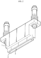
cell lead 20, in order to increase the adhesion between welding targets by pressing the welding targets, a laser welding jig as shown inFIG. 2 is used. The laser welding jig includes a jig body 1, awelding surface 2 located at an end of the jig body 1 to contact a surface of the cell lead, and a laser penetration hole 3 formed through the jig body 1 to penetrate thewelding surface 2. - However, the laser welding jig has a limitation in correcting the height or flatness of the welding target that is changed due to a cell size variation of the batteries, a module assembly deviation or the like, and thus a gap is generated between the welding surface of the jig and the welding target to cause the welding targets lifted. If lifting occurs between the welding targets, the adhesion between the welding targets is lowered to generate a hole in the welding pattern. Thus, its countermeasures are demanded.
- The present disclosure is designed to solve the problems of the related art, and therefore the present disclosure is directed to providing a jig assembly for laser welding, which has a structure capable of improving the welding quality by maintaining the adhesion between a cell lead and a welding surface even though the height or flatness of cell leads is changed.
- The present disclosure is also directed to providing a jig assembly for laser welding, which may compensate for a focal length of the laser corresponding to the height deviation of the cell leads.
- In one aspect of the present disclosure, there is provided a jig assembly for laser welding, comprising: a jig body having a first penetration portion through which a laser for welding is capable of passing; a contact member connected to the jig body to contact a welding target, the contact member having a second penetration portion through which the laser passing through the first penetration portion is capable of passing toward the welding target; a tilting unit having a hinge structure to connect the jig body and the contact member to each other; and an elastic member interposed between the jig body and the contact member to give an elastic force for closely adhering the contact member to the welding target.
- The elastic member may be a coil spring whose both ends are respectively coupled to the jig body and the contact member, and the elastic member may be disposed symmetrically based on the tilting unit.
- The jig assembly for laser welding according to the present disclosure may further comprise spring guides configured to protrude from a lower surface of the jig body and an upper surface of the contact member, respectively, and inserted into both sides of the coil spring to support the coil spring.
- The welding target may be a cell lead, and the first penetration portion formed at the jig body may have an elongated hole structure corresponding to the cell lead.
- The tilting unit may be composed of hinge pieces disposed in parallel to each other with a gap formed therebetween through which a laser is capable of passing, and the gap of the tilting unit may communicate with the first penetration portion so that a laser is capable of passing therethrough.
- The contact member may be composed of a pair of plates disposed in parallel to each other with a gap formed therebetween, the second penetration portion may be provided by the gap of the contact member, and the gap of the tilting unit may communicate with the second penetration portion so that a laser is capable of passing therethrough.
- The jig assembly for laser welding according to the present disclosure may further comprise a displacement sensor disposed to contact an upper surface of the jig body to detect a height deviation of the welding target.
- The pair of plates may be provided to be independently tilted.
- The pair of plates may have a relatively thin lower portion and a relatively thick upper portion to have a stepped form.
- According to the present disclosure, the contact member connected to the jig body may be tilted and elastically adhered to the cell leads. Thus, even though the flatness of the cell leads is changed, the adhesion to the cell leads serving as a welding target may be maintained, thereby preventing a welding defect such as a hole in the welding pattern.
- The accompanying drawings illustrate a preferred embodiment of the present disclosure and together with the foregoing disclosure, serve to provide further understanding of the technical features of the present disclosure, and thus, the present disclosure is not construed as being limited to the drawing.
-
FIG. 1 is a perspective view schematically showing a laser welding process of a general cell lead. -
FIG. 2 is a perspective view showing a conventional jig for laser welding. -
FIG. 3 is a perspective view showing a jig assembly for laser welding according to an embodiment of the present disclosure. -
FIG. 4 is a front view ofFIG. 3 . -
FIG. 5 is a side view ofFIG. 3 . -
FIG. 6 is a bottom view ofFIG. 3 . -
FIG. 7 is a plane view ofFIG. 3 . -
FIGS. 8 and9 are perspective views showing examples where the jig assembly for laser welding according to an embodiment of the present disclosure is used. - Hereinafter, preferred embodiments of the present disclosure will be described in detail with reference to the accompanying drawings. Prior to the description, it should be understood that the terms used in the specification and the appended claims should not be construed as limited to general and dictionary meanings, but interpreted based on the meanings and concepts corresponding to technical aspects of the present disclosure on the basis of the principle that the inventor is allowed to define terms appropriately for the best explanation. Therefore, the description proposed herein is just a preferable example for the purpose of illustrations only, not intended to limit the scope of the disclosure, so it should be understood that other equivalents and modifications could be made thereto without departing from the scope of the disclosure.
-
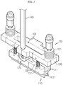
FIG. 3 is a perspective view showing a jig assembly for laser welding according to an embodiment of the present disclosure,FIG. 4 is a front view ofFIG. 3 ,FIG. 5 is a side view ofFIG. 3 ,FIG. 6 is a bottom view ofFIG. 3 , andFIG. 7 is a plane view ofFIG. 3 . - Referring to
FIGS. 3 to 7 , a jig assembly for laser welding according to an embodiment of the present disclosure includes ajig body 100, atilting unit 120 located below thejig body 100 and having a hinge structure, acontact member 110 connected to thejig body 100 by means of thetilting unit 120, and anelastic member 130 interposed between thejig body 100 and thecontact member 110. - The
jig body 100 is composed of a rectangular metal block with a predetermined thickness. Thejig body 100 has afirst penetration portion 101 formed in a thickness direction thereof, and supportrods 150 capable of being coupled to laser welding equipment are assembled at upper surfaces of both ends thereof in a longitudinal direction. Thesupport rod 150 is preferably screwed and fixed to thejig body 100 in a state of being inserted into a bufferingmember 151 having a coil spring structure. - The
first penetration portion 101 is a portion through which a welding laser for welding the cell leads 20 bent to overlap each other passes, and thefirst penetration portion 101 is formed by an elongated hole structure elongated in the longitudinal direction of the lead to correspond to the lead of the cell. - The
tilting unit 120 has a hinge structure which may connect thejig body 100 and thecontact member 110 to each other and tilt thecontact member 110 with respect to thejig body 100. Thetilting unit 120 performs a tilting function for correcting the height or flatness of a welding target that is changed due to a cell size variation of the battery, a module assembly deviation or the like. - For example, the cell leads 20 may be welded in a state where the ends thereof are bent and overlapped on a metal plate-shaped bus bar (not shown). In this case, if the bus bar is not assembled flatly to the battery module, even though the cell leads 20 are pressed, the cell leads 20 may be lifted from the surface of the bus bar. However, in the present disclosure, the
contact member 110 is configured to press the cell leads 20 while being tilted by the tiltingunit 120 as much as a slope of the bus bar. Thus, even though the height or flatness of the cell leads 20 with respect to the bus bar is not constant, the cell leads 20 may be more closely adhered to the bus bar. - The
tilting unit 120 is configured to allow a laser to pass therethrough so that the laser passing through thefirst penetration portion 101 may move to asecond penetration portion 112. In this consideration, thetilting unit 120 is composed of hinge pieces that are disposed to face each other in parallel with a predetermined gap therebetween. The gap of thetilting unit 120 communicates with thefirst penetration portion 101 and thesecond penetration portion 112. - As shown in
FIG. 4 , thetilting unit 120 is composed of a combination of afirst hinge piece 121 extending downward from a lower surface of thejig body 100, asecond hinge piece 122 extending upward from an upper surface of thecontact member 110, and ashaft 123 serving as a tilting center by connecting thefirst hinge piece 121 and thesecond hinge piece 122. - As shown in
FIG. 6 , thefirst hinge piece 121 of thetilting unit 120 is provided in a pair so that the pair offirst hinge pieces 121 are disposed in parallel with each other with a predetermined gap therebetween. Likewise, thesecond hinge piece 122 is also provided in a pair so that the pair of thesecond hinge pieces 122 are disposed in parallel with a predetermined gap therebetween. In addition, theshaft 123 serving as a tilting center is also preferably provided in a pair with a gap therebetween. One of thefirst hinge piece 121 and thesecond hinge piece 122 may be located at an inner side of the other. For example, thesecond hinge piece 122 may be disposed at the inner side of thefirst hinge piece 121. In this structure, thetilting unit 120 may allow the laser incident through thefirst penetration portion 101 to pass toward thesecond penetration portion 112 while providing a tilting function. - In addition, the laser passing through the
second penetration portion 112 may be irradiated onto the upper surface of the cell leads 20 closely adhered to the bus bar. During the laser welding, the cell leads 20 may be kept in close contact with the bus bar by thecontact member 110. - In the present disclosure, since the laser welding range is guided by the
first penetration portion 101 and thesecond penetration portion 112, the welding position and pattern may be uniform and thus the welding quality may be improved. - The
contact member 110 is a member whose front surface is in direct contact with the welding target and is connected to the lower portion of thejig body 100 by thetilting unit 120. Thecontact member 110 has asecond penetration portion 112 having a slit form, which is formed to communicate with thefirst penetration portion 101 and the gap between of thetilting unit 120 so that the laser passing through thefirst penetration portion 101 of thejig body 100 may move toward the welding target. Thecontact member 110 is composed of a pair ofplates 111 that are disposed in parallel with the slit, namely thesecond penetration portion 112, being interposed therebetween. - The pair of
plates 111 may be tilted independently. That is, referring toFIGS. 3 to 5 , theplate 111 and thetilting unit 120 are spaced apart from each other by a predetermined gap that forms thesecond penetration portion 120, and are disposed in a pair in parallel. - Thus, each
plate 111 may be tilted in association with each tiltingunit 120. For example, the rotation direction and slope of oneplate 111 and theother plate 111 may be changed according to the rotation direction and angle of onetilting unit 120 and theother tilting unit 120. In the present disclosure, since the pair of pair ofplates 111 may be tilted independently relative to each other, the cell leads 20 may be closely adhered, especially even though the bus bar (not shown) is twisted. - Each
plate 111 of thecontact member 110 is preferably configured to have a stepped form such that its lower portion is relatively thin and its upper portion 113 (seeFIG. 5 ) is relatively thick. According to this structure, the end portion of thecontact member 110 where the welding surface is located may be designed to have a slim width suitable for the width of thecell lead 20, and also the upper surface of thecontact member 110 may have an area enough to support theelastic member 130, explained later. - The
elastic member 130 is interposed between thejig body 100 and thecontact member 110 to give an elastic force for close adhesion between thecontact member 110 and the cell leads 20 serving as a welding target. If the height or flatness of the welding target is changed, thecontact member 110 is tilted to be closely adhered to the surface of the welding target by means of the elastic force applied from theelastic member 130, thereby compensating the deviation from the welding target. - The
elastic member 130 is formed of a coil spring, and both ends of the coil spring are coupled and mounted to thejig body 100 and thecontact member 110, respectively. Theelastic member 130 is disposed symmetrically based thetilting unit 120. - The
elastic member 130 is supported by spring guides 131 disposed vertically at a lower portion of thejig body 100 and an upper portion of thecontact member 110, respectively. The spring guides 131 protrude from the lower surface of thejig body 100 and the upper surface of thecontact member 110, respectively, to face each other and are inserted into both sides of the correspondingelastic member 130 to support theelastic member 130. According to the arrangement of theelastic member 130 and the spring guides 131, even though a slight height deviation occurs at the cell leads 20, an elastic force is applied sensitively to closely adhere thecontact member 110 and the cell leads 20 to each other. - A
displacement sensor 140 is installed at the upper portion of thejig body 100 to compensate a focal length of the welding laser. A tip of thedisplacement sensor 140 is disposed vertically to be able to contact the upper surface of thejig body 100, thereby detecting a height deviation of the cell leads 20. Thedisplacement sensor 140 may be implemented using a conventional contact-type linear displacement sensor. If the height or flatness of the cell leads 20 is changed due to a cell size deviation of the battery, a module assembly deviation or the like, the height of thejig body 100 is changed, and the resultant height deviation is detected by thedisplacement sensor 140 and reflected to a correction process for increasing (or, decreasing) the focal length of the laser. -
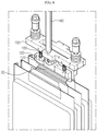
FIGS. 8 and9 are perspective views showing examples where the jig assembly for laser welding according to an embodiment of the present disclosure is used. As shown in the figures, the jig assembly for laser welding according to an embodiment of the present disclosure may be applied to a laser welding process in which cell leads 20 bent to overlap each other are fused to be electrically connected. - As shown in
FIG. 8 , in a state where the welding surface of thecontact member 110 is closely adhered to the cell leads 20, thedisplacement sensor 140 is brought into contact with the upper surface of thejig body 100 to measure the height. If a deviation occurs as a result of the height measurement by thedisplacement sensor 140, the laser welding equipment corrects the focal length of the laser as much as the changed height by reflecting the deviation value. - After that, as shown in
FIG. 9 , in a state where the cell leads 20 are pressed with thecontact member 110, a laser L is irradiated to weld the cell leads 20. At this time, the laser L passes through thefirst penetration portion 101 of thejig body 100, the gap of thetilting unit 120 and thesecond penetration portion 112 of thecontact member 110 in order, and is irradiated to the cell leads 20 to fuse the cell leads 20. - Since the
contact member 110 is capable of being tilted and elastically adhered to the cell leads 20 by thetilting unit 120 and theelastic member 130, thecontact member 110 is able to be kept in close contact with the cell leads 20 even though the flatness (angle) of the cell leads 20 is changed, thereby preventing a problem that a hole is generated in the welding pattern. - The present disclosure has been described in detail. However, it should be understood that the detailed description and specific examples, while indicating preferred embodiments of the disclosure, are given by way of illustration only, since various changes and modifications within the scope of the disclosure will become apparent to those skilled in the art from this detailed description.
Claims (9)
- A jig assembly for laser welding, comprising:a jig body having a first penetration portion through which a laser for welding is capable of passing;a contact member connected to the jig body to contact a welding target, the contact member having a second penetration portion through which the laser passing through the first penetration portion is capable of passing toward the welding target;a tilting unit having a hinge structure to connect the jig body and the contact member to each other; andan elastic member interposed between the jig body and the contact member to give an elastic force for closely adhering the contact member to the welding target.
- The jig assembly for laser welding according to claim 1,
wherein the elastic member is a coil spring whose both ends are respectively coupled to the jig body and the contact member, and
wherein the elastic member is disposed symmetrically based on the tilting unit. - The jig assembly for laser welding according to claim 2, further comprising:
spring guides configured to protrude from a lower surface of the jig body and an upper surface of the contact member, respectively, and inserted into both sides of the coil spring to support the coil spring. - The jig assembly for laser welding according to claim 1,
wherein the welding target is a cell lead, and
wherein the first penetration portion formed at the jig body has an elongated hole structure corresponding to the cell lead. - The jig assembly for laser welding according to claim 4,
wherein the tilting unit is composed of hinge pieces disposed in parallel to each other with a gap formed therebetween through which a laser is capable of passing, and
wherein the gap of the tilting unit communicates with the first penetration portion so that a laser is capable of passing therethrough. - The jig assembly for laser welding according to claim 5,
wherein the contact member is composed of a pair of plates disposed in parallel to each other with a gap formed therebetween,
wherein the second penetration portion is provided by the gap of the contact member, and
wherein the gap of the tilting unit communicates with the second penetration portion so that a laser is capable of passing therethrough. - The jig assembly for laser welding according to claim 1, further comprising:
a displacement sensor disposed to contact an upper surface of the jig body to detect a height deviation of the welding target. - The jig assembly for laser welding according to claim 6,
wherein the pair of plates are provided to be independently tilted. - The jig assembly for laser welding according to claim 6,
wherein the pair of plates has a relatively thin lower portion and a relatively thick upper portion to have a stepped form.
Priority Applications (1)
| Application Number | Priority Date | Filing Date | Title |
|---|---|---|---|
| PL18739079T PL3453482T3 (en) | 2017-01-11 | 2018-01-05 | Jig assembly for laser welding |
Applications Claiming Priority (2)
| Application Number | Priority Date | Filing Date | Title |
|---|---|---|---|
| KR1020170004403A KR102090787B1 (en) | 2017-01-11 | 2017-01-11 | Jig assembly for laser welding |
| PCT/KR2018/000291 WO2018131843A1 (en) | 2017-01-11 | 2018-01-05 | Laser welding jig assembly |
Publications (3)
| Publication Number | Publication Date |
|---|---|
| EP3453482A1 true EP3453482A1 (en) | 2019-03-13 |
| EP3453482A4 EP3453482A4 (en) | 2019-09-18 |
| EP3453482B1 EP3453482B1 (en) | 2020-09-09 |
Family
ID=62840508
Family Applications (1)
| Application Number | Title | Priority Date | Filing Date |
|---|---|---|---|
| EP18739079.4A Active EP3453482B1 (en) | 2017-01-11 | 2018-01-05 | Jig assembly for laser welding |
Country Status (7)
| Country | Link |
|---|---|
| US (1) | US11020842B2 (en) |
| EP (1) | EP3453482B1 (en) |
| JP (1) | JP6651654B2 (en) |
| KR (1) | KR102090787B1 (en) |
| CN (1) | CN109311130B (en) |
| PL (1) | PL3453482T3 (en) |
| WO (1) | WO2018131843A1 (en) |
Cited By (1)
| Publication number | Priority date | Publication date | Assignee | Title |
|---|---|---|---|---|
| WO2022207867A1 (en) * | 2021-03-31 | 2022-10-06 | Jaguar Land Rover Limited | Laser welding position determination |
Families Citing this family (31)
| Publication number | Priority date | Publication date | Assignee | Title |
|---|---|---|---|---|
| KR102101429B1 (en) * | 2016-05-18 | 2020-04-16 | 주식회사 엘지화학 | Lead welding apparatus, battery module manufactured by the lead welding apparatus and battery pack comprising the battery module |
| KR102155888B1 (en) * | 2017-09-11 | 2020-09-14 | 주식회사 엘지화학 | Laser welding jig and laser welding apparatus comprising the same |
| KR102324264B1 (en) | 2018-12-21 | 2021-11-08 | 주식회사 엘지에너지솔루션 | A pressing jig apparatus that closely contacts electrode lead with bus bar and a battery module manufacturing system comprising the same |
| KR102412403B1 (en) | 2018-12-26 | 2022-06-22 | 주식회사 엘지에너지솔루션 | Battery module, battery pack comprising the battery module and vehicle comprising the battery pack |
| CN109822239A (en) * | 2019-03-14 | 2019-05-31 | 广东顺德华焯机械科技有限公司 | A kind of new energy battery case synchronous welding component |
| KR102043114B1 (en) * | 2019-04-25 | 2019-11-27 | 백영진 | Welding guide device for electrode lead of secondary battery cell and welding guide system using the same |
| JP6704081B1 (en) * | 2019-07-05 | 2020-06-03 | 住友化学株式会社 | Method for processing end surface of laminated body, method for manufacturing end surface processed film, and end surface processing apparatus |
| KR102846625B1 (en) * | 2019-08-22 | 2025-08-19 | (주)제이앤디테크 | Secondary battery manufacturing apparatus and pressing module for the same |
| KR102233222B1 (en) * | 2019-10-14 | 2021-03-29 | 한국기계연구원 | Apparatus for underwater laser cutting and method of underwater laser cutting |
| KR102836078B1 (en) * | 2019-10-18 | 2025-07-17 | 주식회사 엘지에너지솔루션 | Welding jig |
| JP7562965B2 (en) * | 2020-03-10 | 2024-10-08 | 富士電機株式会社 | Manufacturing method, manufacturing apparatus, jig assembly, semiconductor module and vehicle |
| US11450877B2 (en) * | 2020-03-16 | 2022-09-20 | GM Global Technology Operations LLC | Tooling and method for alignment and assembly of battery module |
| IT202000006016A1 (en) * | 2020-03-20 | 2021-09-20 | Comau Spa | "Equipment for assembling battery cells or battery modules" |
| KR102820205B1 (en) | 2020-04-17 | 2025-06-12 | 주식회사 엘지에너지솔루션 | Jig for laser welding |
| KR102777991B1 (en) | 2020-04-28 | 2025-03-06 | 주식회사 엘지에너지솔루션 | Jig for laser welding |
| KR102862105B1 (en) | 2020-05-14 | 2025-09-18 | 주식회사 엘지에너지솔루션 | Jig for laser welding |
| KR102851616B1 (en) | 2020-07-15 | 2025-08-28 | 주식회사 엘지에너지솔루션 | Electrode Lead Bending and Welding Device and Welding Method Using the Same |
| KR102716986B1 (en) | 2020-07-20 | 2024-10-15 | 주식회사 엘지에너지솔루션 | Ultrasonic welding device and method for secondary battery |
| KR102923760B1 (en) * | 2020-11-04 | 2026-02-05 | 주식회사 엘지에너지솔루션 | Welding Stick Jig For Welding Electrode Lead And Electrode Tab |
| KR102825913B1 (en) * | 2020-11-10 | 2025-06-27 | 주식회사 엘지에너지솔루션 | Welding apparatus for button-type secondary battery |
| KR102948498B1 (en) * | 2021-03-16 | 2026-04-03 | 현대자동차 주식회사 | Assembling apparatus of battery module and assembling method using the same |
| CN113708020B (en) * | 2021-08-24 | 2023-05-05 | 湖北亿纬动力有限公司 | Vibration reduction method for tab welding and clamping tool |
| JP7711555B2 (en) * | 2021-10-27 | 2025-07-23 | トヨタ自動車株式会社 | Manufacturing method of energy storage module |
| CN114085034A (en) * | 2021-11-10 | 2022-02-25 | 华为技术有限公司 | Welding apparatus and welding method |
| KR102581274B1 (en) * | 2022-01-07 | 2023-09-21 | 주식회사 성우하이텍 | Core for assembling cross member of battery case and mounting jig |
| KR102581275B1 (en) * | 2022-01-07 | 2023-09-21 | 주식회사 성우하이텍 | Cross member assemby system |
| WO2023163469A1 (en) * | 2022-02-22 | 2023-08-31 | 주식회사 엘지에너지솔루션 | Electrode lead alignment masking device |
| CN115194685B (en) * | 2022-07-21 | 2024-11-22 | 敦南科技(无锡)有限公司 | An assembly tooling structure and method for fixing the internal lens of an industrial detection sensor |
| EP4371693A1 (en) * | 2022-11-18 | 2024-05-22 | Bergmann & Steffen GmbH | Method for laser welding a plurality of assemblies |
| KR102874324B1 (en) * | 2023-12-15 | 2025-10-28 | 주식회사 액스비스 | Cap Assembly Welding Jig System |
| KR20250109493A (en) | 2024-01-10 | 2025-07-17 | 주식회사 엘지에너지솔루션 | Folding apparatus |
Family Cites Families (25)
| Publication number | Priority date | Publication date | Assignee | Title |
|---|---|---|---|---|
| US4678289A (en) * | 1984-09-25 | 1987-07-07 | Siemens Aktiengesellschaft | Apparatus for the deflection of a light beam |
| EP0412584B1 (en) * | 1987-04-30 | 1993-09-22 | Amada Company Limited | Laser-punch composite processing machine |
| IT1211558B (en) * | 1987-11-26 | 1989-11-03 | Bruno Bisiach | LASER BEAM ROBOT FOR CUTTING AND WELDING |
| JP3087373B2 (en) * | 1991-09-18 | 2000-09-11 | 株式会社デンソー | Metal foil joining method and joining device |
| JP3126789B2 (en) * | 1992-01-31 | 2001-01-22 | 株式会社アマダ | Laser welding equipment |
| JP2575398Y2 (en) * | 1993-02-16 | 1998-06-25 | いすゞ自動車株式会社 | Laser welding jig |
| JP4184663B2 (en) * | 1999-10-28 | 2008-11-19 | 古河電池株式会社 | Manufacturing method of lead-acid battery and jig for manufacturing the same |
| JP3929664B2 (en) * | 1999-12-08 | 2007-06-13 | 株式会社リコー | Multi-beam light source unit and adjustment method thereof, positioning jig, and image forming apparatus |
| JP2001347384A (en) * | 2000-06-06 | 2001-12-18 | Fuji Xerox Co Ltd | Thin film welding apparatus, thin film welding method, welding thin film belt, image forming apparatus using welding thin film belt |
| KR100846658B1 (en) * | 2007-05-09 | 2008-07-16 | 한국기계연구원 | Welding method using laser jig and laser jig for joining thin plates |
| TW200937062A (en) * | 2008-02-19 | 2009-09-01 | Young Optics Inc | Position adjustment mechanism for laser optics and laser assembly having the same |
| JP5248344B2 (en) | 2009-01-20 | 2013-07-31 | 本田技研工業株式会社 | Laser welding method |
| KR101105227B1 (en) | 2009-04-13 | 2012-01-13 | 에스티엑스조선해양 주식회사 | Cylindrical grinding device |
| CN201900387U (en) * | 2010-12-20 | 2011-07-20 | 天津力神电池股份有限公司 | Laser welding fixture for power battery |
| DE102011103246A1 (en) * | 2011-06-03 | 2012-12-06 | Volkswagen Aktiengesellschaft | Method and device for joining components by means of energy-beam welding |
| KR20130070392A (en) * | 2011-12-19 | 2013-06-27 | 주식회사 성우하이텍 | A jig drive of laser welding |
| KR101571210B1 (en) | 2013-09-04 | 2015-11-23 | 주식회사 엘지화학 | Jig apparatus for secondary battery |
| JP2015119072A (en) * | 2013-12-19 | 2015-06-25 | 富士電機株式会社 | Laser welding method, laser welding jig, semiconductor device |
| JP6315672B2 (en) * | 2014-03-10 | 2018-04-25 | 川崎重工業株式会社 | Overlay welding system |
| KR101750597B1 (en) * | 2014-04-30 | 2017-06-23 | 주식회사 엘지화학 | Laser welding apparatus |
| KR101799563B1 (en) * | 2015-02-27 | 2017-11-20 | 주식회사 엘지화학 | Jig for Laser Welding for Battery Pack |
| JP6619300B2 (en) * | 2016-07-27 | 2019-12-11 | 株式会社神戸製鋼所 | Welding equipment |
| CN107868958B (en) * | 2017-12-01 | 2023-12-05 | 浙江工业大学 | A flexible adaptive composite carbon brush type electromagnetic composite field synchronized laser cladding device |
| CN107824969A (en) * | 2017-12-15 | 2018-03-23 | 江苏镭腾能源科技有限公司 | A kind of welding position Drift adjusting mechanism for flexible of lithium battery cap |
| KR102206212B1 (en) * | 2018-12-10 | 2021-01-22 | 에스 알 씨 주식회사 | Geared product with reinforced deposition surfaces and deposition system used for manufacturing the same |
-
2017
- 2017-01-11 KR KR1020170004403A patent/KR102090787B1/en active Active
-
2018
- 2018-01-05 PL PL18739079T patent/PL3453482T3/en unknown
- 2018-01-05 WO PCT/KR2018/000291 patent/WO2018131843A1/en not_active Ceased
- 2018-01-05 US US16/302,845 patent/US11020842B2/en active Active
- 2018-01-05 EP EP18739079.4A patent/EP3453482B1/en active Active
- 2018-01-05 JP JP2018559798A patent/JP6651654B2/en active Active
- 2018-01-05 CN CN201880002382.8A patent/CN109311130B/en active Active
Cited By (1)
| Publication number | Priority date | Publication date | Assignee | Title |
|---|---|---|---|---|
| WO2022207867A1 (en) * | 2021-03-31 | 2022-10-06 | Jaguar Land Rover Limited | Laser welding position determination |
Also Published As
| Publication number | Publication date |
|---|---|
| KR102090787B1 (en) | 2020-03-18 |
| PL3453482T3 (en) | 2021-02-08 |
| KR20180082914A (en) | 2018-07-19 |
| EP3453482A4 (en) | 2019-09-18 |
| EP3453482B1 (en) | 2020-09-09 |
| CN109311130A (en) | 2019-02-05 |
| JP6651654B2 (en) | 2020-02-19 |
| US20190321945A1 (en) | 2019-10-24 |
| JP2019520986A (en) | 2019-07-25 |
| US11020842B2 (en) | 2021-06-01 |
| WO2018131843A1 (en) | 2018-07-19 |
| CN109311130B (en) | 2020-12-08 |
Similar Documents
| Publication | Publication Date | Title |
|---|---|---|
| US11020842B2 (en) | Jig assembly for laser welding | |
| CN111279513B (en) | Battery pack including battery pack frame capable of preventing welding defect and pressing jig for preparing the same | |
| US11011804B2 (en) | Battery module | |
| EP2330661B1 (en) | Rechargeable battery | |
| US20210098766A1 (en) | Ultrasonic welding system of rechargeable battery and manufacturing method of rechargeable battery using the same | |
| EP3670066A1 (en) | Jig for spot welding | |
| CN108370017B (en) | Bus bar and electricity storage module | |
| EP2819210B1 (en) | Battery module | |
| CN108352489B (en) | Battery pack and method for manufacturing the same | |
| US20070141458A1 (en) | Battery pack | |
| US20180287111A1 (en) | Method for assembling battery pack, and battery pack | |
| KR102165327B1 (en) | Jig for contact between two electrode leads and welding method of electrode leads | |
| US10418602B2 (en) | Battery pack | |
| KR102758792B1 (en) | Method for Optimizing Ultrasonic Welding Process of Lithium Secondary Battery and Apparatus Thereof | |
| US11912214B2 (en) | Wiring module and power storage module | |
| CN108695457A (en) | Battery pack | |
| US20230344090A1 (en) | Battery module and method for manufacturing same | |
| KR20170095067A (en) | Battery Cell Having Electrode Tabs and Electrode Lead Laser-welded to Each Other | |
| US20230207856A1 (en) | Pouch-Shaped Battery Sealing Apparatus Including Stopper and Pouch-Shaped Battery Sealing Method Using the Same | |
| KR102363196B1 (en) | Gripper for charging and discharging of pouch type battery, and charging and discharging device of pouch type battery having same | |
| JP2020177851A (en) | Rechargeable battery module | |
| CN220574982U (en) | Ultrasonic welding equipment | |
| KR102596162B1 (en) | Ultrasonic welding machine with horn level adjustment function | |
| JP2024138573A (en) | Battery module and manufacturing method thereof | |
| US12290877B2 (en) | Method for producing a traction battery of a motor vehicle and corresponding production device |
Legal Events
| Date | Code | Title | Description |
|---|---|---|---|
| STAA | Information on the status of an ep patent application or granted ep patent |
Free format text: STATUS: THE INTERNATIONAL PUBLICATION HAS BEEN MADE |
|
| PUAI | Public reference made under article 153(3) epc to a published international application that has entered the european phase |
Free format text: ORIGINAL CODE: 0009012 |
|
| STAA | Information on the status of an ep patent application or granted ep patent |
Free format text: STATUS: REQUEST FOR EXAMINATION WAS MADE |
|
| 17P | Request for examination filed |
Effective date: 20181204 |
|
| AK | Designated contracting states |
Kind code of ref document: A1 Designated state(s): AL AT BE BG CH CY CZ DE DK EE ES FI FR GB GR HR HU IE IS IT LI LT LU LV MC MK MT NL NO PL PT RO RS SE SI SK SM TR |
|
| AX | Request for extension of the european patent |
Extension state: BA ME |
|
| A4 | Supplementary search report drawn up and despatched |
Effective date: 20190819 |
|
| RIC1 | Information provided on ipc code assigned before grant |
Ipc: H01M 2/20 20060101ALI20190812BHEP Ipc: B25B 11/00 20060101ALI20190812BHEP Ipc: B23K 101/36 20060101ALI20190812BHEP Ipc: B23K 37/04 20060101AFI20190812BHEP Ipc: H01M 2/10 20060101ALI20190812BHEP Ipc: B23K 26/70 20140101ALI20190812BHEP Ipc: B23K 26/21 20140101ALI20190812BHEP |
|
| DAV | Request for validation of the european patent (deleted) | ||
| DAX | Request for extension of the european patent (deleted) | ||
| GRAP | Despatch of communication of intention to grant a patent |
Free format text: ORIGINAL CODE: EPIDOSNIGR1 |
|
| STAA | Information on the status of an ep patent application or granted ep patent |
Free format text: STATUS: GRANT OF PATENT IS INTENDED |
|
| INTG | Intention to grant announced |
Effective date: 20200617 |
|
| GRAS | Grant fee paid |
Free format text: ORIGINAL CODE: EPIDOSNIGR3 |
|
| GRAA | (expected) grant |
Free format text: ORIGINAL CODE: 0009210 |
|
| STAA | Information on the status of an ep patent application or granted ep patent |
Free format text: STATUS: THE PATENT HAS BEEN GRANTED |
|
| AK | Designated contracting states |
Kind code of ref document: B1 Designated state(s): AL AT BE BG CH CY CZ DE DK EE ES FI FR GB GR HR HU IE IS IT LI LT LU LV MC MK MT NL NO PL PT RO RS SE SI SK SM TR |
|
| REG | Reference to a national code |
Ref country code: GB Ref legal event code: FG4D |
|
| REG | Reference to a national code |
Ref country code: AT Ref legal event code: REF Ref document number: 1310976 Country of ref document: AT Kind code of ref document: T Effective date: 20200915 Ref country code: CH Ref legal event code: EP |
|
| REG | Reference to a national code |
Ref country code: IE Ref legal event code: FG4D |
|
| REG | Reference to a national code |
Ref country code: DE Ref legal event code: R096 Ref document number: 602018007721 Country of ref document: DE |
|
| REG | Reference to a national code |
Ref country code: SE Ref legal event code: TRGR |
|
| REG | Reference to a national code |
Ref country code: LT Ref legal event code: MG4D |
|
| PG25 | Lapsed in a contracting state [announced via postgrant information from national office to epo] |
Ref country code: HR Free format text: LAPSE BECAUSE OF FAILURE TO SUBMIT A TRANSLATION OF THE DESCRIPTION OR TO PAY THE FEE WITHIN THE PRESCRIBED TIME-LIMIT Effective date: 20200909 Ref country code: NO Free format text: LAPSE BECAUSE OF FAILURE TO SUBMIT A TRANSLATION OF THE DESCRIPTION OR TO PAY THE FEE WITHIN THE PRESCRIBED TIME-LIMIT Effective date: 20201209 Ref country code: BG Free format text: LAPSE BECAUSE OF FAILURE TO SUBMIT A TRANSLATION OF THE DESCRIPTION OR TO PAY THE FEE WITHIN THE PRESCRIBED TIME-LIMIT Effective date: 20201209 Ref country code: GR Free format text: LAPSE BECAUSE OF FAILURE TO SUBMIT A TRANSLATION OF THE DESCRIPTION OR TO PAY THE FEE WITHIN THE PRESCRIBED TIME-LIMIT Effective date: 20201210 Ref country code: LT Free format text: LAPSE BECAUSE OF FAILURE TO SUBMIT A TRANSLATION OF THE DESCRIPTION OR TO PAY THE FEE WITHIN THE PRESCRIBED TIME-LIMIT Effective date: 20200909 Ref country code: FI Free format text: LAPSE BECAUSE OF FAILURE TO SUBMIT A TRANSLATION OF THE DESCRIPTION OR TO PAY THE FEE WITHIN THE PRESCRIBED TIME-LIMIT Effective date: 20200909 |
|
| REG | Reference to a national code |
Ref country code: AT Ref legal event code: MK05 Ref document number: 1310976 Country of ref document: AT Kind code of ref document: T Effective date: 20200909 |
|
| REG | Reference to a national code |
Ref country code: NL Ref legal event code: MP Effective date: 20200909 |
|
| PG25 | Lapsed in a contracting state [announced via postgrant information from national office to epo] |
Ref country code: LV Free format text: LAPSE BECAUSE OF FAILURE TO SUBMIT A TRANSLATION OF THE DESCRIPTION OR TO PAY THE FEE WITHIN THE PRESCRIBED TIME-LIMIT Effective date: 20200909 Ref country code: RS Free format text: LAPSE BECAUSE OF FAILURE TO SUBMIT A TRANSLATION OF THE DESCRIPTION OR TO PAY THE FEE WITHIN THE PRESCRIBED TIME-LIMIT Effective date: 20200909 |
|
| PG25 | Lapsed in a contracting state [announced via postgrant information from national office to epo] |
Ref country code: EE Free format text: LAPSE BECAUSE OF FAILURE TO SUBMIT A TRANSLATION OF THE DESCRIPTION OR TO PAY THE FEE WITHIN THE PRESCRIBED TIME-LIMIT Effective date: 20200909 Ref country code: CZ Free format text: LAPSE BECAUSE OF FAILURE TO SUBMIT A TRANSLATION OF THE DESCRIPTION OR TO PAY THE FEE WITHIN THE PRESCRIBED TIME-LIMIT Effective date: 20200909 Ref country code: RO Free format text: LAPSE BECAUSE OF FAILURE TO SUBMIT A TRANSLATION OF THE DESCRIPTION OR TO PAY THE FEE WITHIN THE PRESCRIBED TIME-LIMIT Effective date: 20200909 Ref country code: PT Free format text: LAPSE BECAUSE OF FAILURE TO SUBMIT A TRANSLATION OF THE DESCRIPTION OR TO PAY THE FEE WITHIN THE PRESCRIBED TIME-LIMIT Effective date: 20210111 Ref country code: SM Free format text: LAPSE BECAUSE OF FAILURE TO SUBMIT A TRANSLATION OF THE DESCRIPTION OR TO PAY THE FEE WITHIN THE PRESCRIBED TIME-LIMIT Effective date: 20200909 |
|
| PG25 | Lapsed in a contracting state [announced via postgrant information from national office to epo] |
Ref country code: AT Free format text: LAPSE BECAUSE OF FAILURE TO SUBMIT A TRANSLATION OF THE DESCRIPTION OR TO PAY THE FEE WITHIN THE PRESCRIBED TIME-LIMIT Effective date: 20200909 Ref country code: AL Free format text: LAPSE BECAUSE OF FAILURE TO SUBMIT A TRANSLATION OF THE DESCRIPTION OR TO PAY THE FEE WITHIN THE PRESCRIBED TIME-LIMIT Effective date: 20200909 Ref country code: ES Free format text: LAPSE BECAUSE OF FAILURE TO SUBMIT A TRANSLATION OF THE DESCRIPTION OR TO PAY THE FEE WITHIN THE PRESCRIBED TIME-LIMIT Effective date: 20200909 Ref country code: IS Free format text: LAPSE BECAUSE OF FAILURE TO SUBMIT A TRANSLATION OF THE DESCRIPTION OR TO PAY THE FEE WITHIN THE PRESCRIBED TIME-LIMIT Effective date: 20210109 |
|
| REG | Reference to a national code |
Ref country code: DE Ref legal event code: R097 Ref document number: 602018007721 Country of ref document: DE |
|
| PG25 | Lapsed in a contracting state [announced via postgrant information from national office to epo] |
Ref country code: SK Free format text: LAPSE BECAUSE OF FAILURE TO SUBMIT A TRANSLATION OF THE DESCRIPTION OR TO PAY THE FEE WITHIN THE PRESCRIBED TIME-LIMIT Effective date: 20200909 |
|
| PLBE | No opposition filed within time limit |
Free format text: ORIGINAL CODE: 0009261 |
|
| STAA | Information on the status of an ep patent application or granted ep patent |
Free format text: STATUS: NO OPPOSITION FILED WITHIN TIME LIMIT |
|
| 26N | No opposition filed |
Effective date: 20210610 |
|
| PG25 | Lapsed in a contracting state [announced via postgrant information from national office to epo] |
Ref country code: MC Free format text: LAPSE BECAUSE OF FAILURE TO SUBMIT A TRANSLATION OF THE DESCRIPTION OR TO PAY THE FEE WITHIN THE PRESCRIBED TIME-LIMIT Effective date: 20200909 Ref country code: DK Free format text: LAPSE BECAUSE OF FAILURE TO SUBMIT A TRANSLATION OF THE DESCRIPTION OR TO PAY THE FEE WITHIN THE PRESCRIBED TIME-LIMIT Effective date: 20200909 Ref country code: SI Free format text: LAPSE BECAUSE OF FAILURE TO SUBMIT A TRANSLATION OF THE DESCRIPTION OR TO PAY THE FEE WITHIN THE PRESCRIBED TIME-LIMIT Effective date: 20200909 |
|
| REG | Reference to a national code |
Ref country code: CH Ref legal event code: PL |
|
| PG25 | Lapsed in a contracting state [announced via postgrant information from national office to epo] |
Ref country code: LU Free format text: LAPSE BECAUSE OF NON-PAYMENT OF DUE FEES Effective date: 20210105 |
|
| REG | Reference to a national code |
Ref country code: BE Ref legal event code: MM Effective date: 20210131 |
|
| PG25 | Lapsed in a contracting state [announced via postgrant information from national office to epo] |
Ref country code: IT Free format text: LAPSE BECAUSE OF FAILURE TO SUBMIT A TRANSLATION OF THE DESCRIPTION OR TO PAY THE FEE WITHIN THE PRESCRIBED TIME-LIMIT Effective date: 20200909 |
|
| PG25 | Lapsed in a contracting state [announced via postgrant information from national office to epo] |
Ref country code: LI Free format text: LAPSE BECAUSE OF NON-PAYMENT OF DUE FEES Effective date: 20210131 Ref country code: CH Free format text: LAPSE BECAUSE OF NON-PAYMENT OF DUE FEES Effective date: 20210131 |
|
| PG25 | Lapsed in a contracting state [announced via postgrant information from national office to epo] |
Ref country code: IE Free format text: LAPSE BECAUSE OF NON-PAYMENT OF DUE FEES Effective date: 20210105 |
|
| PG25 | Lapsed in a contracting state [announced via postgrant information from national office to epo] |
Ref country code: BE Free format text: LAPSE BECAUSE OF NON-PAYMENT OF DUE FEES Effective date: 20210131 |
|
| P01 | Opt-out of the competence of the unified patent court (upc) registered |
Effective date: 20230512 |
|
| PG25 | Lapsed in a contracting state [announced via postgrant information from national office to epo] |
Ref country code: NL Free format text: LAPSE BECAUSE OF NON-PAYMENT OF DUE FEES Effective date: 20200923 Ref country code: CY Free format text: LAPSE BECAUSE OF FAILURE TO SUBMIT A TRANSLATION OF THE DESCRIPTION OR TO PAY THE FEE WITHIN THE PRESCRIBED TIME-LIMIT Effective date: 20200909 |
|
| PG25 | Lapsed in a contracting state [announced via postgrant information from national office to epo] |
Ref country code: HU Free format text: LAPSE BECAUSE OF FAILURE TO SUBMIT A TRANSLATION OF THE DESCRIPTION OR TO PAY THE FEE WITHIN THE PRESCRIBED TIME-LIMIT; INVALID AB INITIO Effective date: 20180105 |
|
| REG | Reference to a national code |
Ref country code: GB Ref legal event code: 732E Free format text: REGISTERED BETWEEN 20230824 AND 20230831 |
|
| REG | Reference to a national code |
Ref country code: DE Ref legal event code: R081 Ref document number: 602018007721 Country of ref document: DE Owner name: LG ENERGY SOLUTION, LTD., KR Free format text: FORMER OWNER: LG CHEM, LTD., SEOUL, KR |
|
| PG25 | Lapsed in a contracting state [announced via postgrant information from national office to epo] |
Ref country code: MK Free format text: LAPSE BECAUSE OF FAILURE TO SUBMIT A TRANSLATION OF THE DESCRIPTION OR TO PAY THE FEE WITHIN THE PRESCRIBED TIME-LIMIT Effective date: 20200909 |
|
| PG25 | Lapsed in a contracting state [announced via postgrant information from national office to epo] |
Ref country code: MT Free format text: LAPSE BECAUSE OF FAILURE TO SUBMIT A TRANSLATION OF THE DESCRIPTION OR TO PAY THE FEE WITHIN THE PRESCRIBED TIME-LIMIT Effective date: 20200909 |
|
| PG25 | Lapsed in a contracting state [announced via postgrant information from national office to epo] |
Ref country code: TR Free format text: LAPSE BECAUSE OF FAILURE TO SUBMIT A TRANSLATION OF THE DESCRIPTION OR TO PAY THE FEE WITHIN THE PRESCRIBED TIME-LIMIT Effective date: 20200909 |
|
| PGFP | Annual fee paid to national office [announced via postgrant information from national office to epo] |
Ref country code: GB Payment date: 20251222 Year of fee payment: 9 |
|
| PGFP | Annual fee paid to national office [announced via postgrant information from national office to epo] |
Ref country code: FR Payment date: 20251223 Year of fee payment: 9 |
|
| PGFP | Annual fee paid to national office [announced via postgrant information from national office to epo] |
Ref country code: SE Payment date: 20251223 Year of fee payment: 9 |
|
| PGFP | Annual fee paid to national office [announced via postgrant information from national office to epo] |
Ref country code: PL Payment date: 20251223 Year of fee payment: 9 |
|
| PGFP | Annual fee paid to national office [announced via postgrant information from national office to epo] |
Ref country code: DE Payment date: 20251222 Year of fee payment: 9 |