EP3453417A1 - Syringe barrel and pre-filled syringe - Google Patents
Syringe barrel and pre-filled syringe Download PDFInfo
- Publication number
- EP3453417A1 EP3453417A1 EP17789538.0A EP17789538A EP3453417A1 EP 3453417 A1 EP3453417 A1 EP 3453417A1 EP 17789538 A EP17789538 A EP 17789538A EP 3453417 A1 EP3453417 A1 EP 3453417A1
- Authority
- EP
- European Patent Office
- Prior art keywords
- barrel
- circumferential surface
- scale
- syringe barrel
- stepped structure
- Prior art date
- Legal status (The legal status is an assumption and is not a legal conclusion. Google has not performed a legal analysis and makes no representation as to the accuracy of the status listed.)
- Granted
Links
Images




Classifications
-
- A—HUMAN NECESSITIES
- A61—MEDICAL OR VETERINARY SCIENCE; HYGIENE
- A61M—DEVICES FOR INTRODUCING MEDIA INTO, OR ONTO, THE BODY; DEVICES FOR TRANSDUCING BODY MEDIA OR FOR TAKING MEDIA FROM THE BODY; DEVICES FOR PRODUCING OR ENDING SLEEP OR STUPOR
- A61M5/00—Devices for bringing media into the body in a subcutaneous, intra-vascular or intramuscular way; Accessories therefor, e.g. filling or cleaning devices, arm rests
- A61M5/178—Syringes
- A61M5/31—Details
- A61M5/3129—Syringe barrels
-
- A—HUMAN NECESSITIES
- A61—MEDICAL OR VETERINARY SCIENCE; HYGIENE
- A61M—DEVICES FOR INTRODUCING MEDIA INTO, OR ONTO, THE BODY; DEVICES FOR TRANSDUCING BODY MEDIA OR FOR TAKING MEDIA FROM THE BODY; DEVICES FOR PRODUCING OR ENDING SLEEP OR STUPOR
- A61M5/00—Devices for bringing media into the body in a subcutaneous, intra-vascular or intramuscular way; Accessories therefor, e.g. filling or cleaning devices, arm rests
- A61M5/178—Syringes
-
- A—HUMAN NECESSITIES
- A61—MEDICAL OR VETERINARY SCIENCE; HYGIENE
- A61M—DEVICES FOR INTRODUCING MEDIA INTO, OR ONTO, THE BODY; DEVICES FOR TRANSDUCING BODY MEDIA OR FOR TAKING MEDIA FROM THE BODY; DEVICES FOR PRODUCING OR ENDING SLEEP OR STUPOR
- A61M5/00—Devices for bringing media into the body in a subcutaneous, intra-vascular or intramuscular way; Accessories therefor, e.g. filling or cleaning devices, arm rests
- A61M5/178—Syringes
- A61M5/31—Details
- A61M2005/3125—Display means, e.g. to indicate dose setting
- A61M2005/3126—Display means, e.g. to indicate dose setting related to dosing
-
- A—HUMAN NECESSITIES
- A61—MEDICAL OR VETERINARY SCIENCE; HYGIENE
- A61M—DEVICES FOR INTRODUCING MEDIA INTO, OR ONTO, THE BODY; DEVICES FOR TRANSDUCING BODY MEDIA OR FOR TAKING MEDIA FROM THE BODY; DEVICES FOR PRODUCING OR ENDING SLEEP OR STUPOR
- A61M5/00—Devices for bringing media into the body in a subcutaneous, intra-vascular or intramuscular way; Accessories therefor, e.g. filling or cleaning devices, arm rests
- A61M5/178—Syringes
- A61M5/31—Details
- A61M5/3129—Syringe barrels
- A61M2005/3131—Syringe barrels specially adapted for improving sealing or sliding
-
- A—HUMAN NECESSITIES
- A61—MEDICAL OR VETERINARY SCIENCE; HYGIENE
- A61M—DEVICES FOR INTRODUCING MEDIA INTO, OR ONTO, THE BODY; DEVICES FOR TRANSDUCING BODY MEDIA OR FOR TAKING MEDIA FROM THE BODY; DEVICES FOR PRODUCING OR ENDING SLEEP OR STUPOR
- A61M2205/00—General characteristics of the apparatus
- A61M2205/02—General characteristics of the apparatus characterised by a particular materials
- A61M2205/0238—General characteristics of the apparatus characterised by a particular materials the material being a coating or protective layer
-
- A—HUMAN NECESSITIES
- A61—MEDICAL OR VETERINARY SCIENCE; HYGIENE
- A61M—DEVICES FOR INTRODUCING MEDIA INTO, OR ONTO, THE BODY; DEVICES FOR TRANSDUCING BODY MEDIA OR FOR TAKING MEDIA FROM THE BODY; DEVICES FOR PRODUCING OR ENDING SLEEP OR STUPOR
- A61M5/00—Devices for bringing media into the body in a subcutaneous, intra-vascular or intramuscular way; Accessories therefor, e.g. filling or cleaning devices, arm rests
- A61M5/001—Apparatus specially adapted for cleaning or sterilising syringes or needles
-
- A—HUMAN NECESSITIES
- A61—MEDICAL OR VETERINARY SCIENCE; HYGIENE
- A61M—DEVICES FOR INTRODUCING MEDIA INTO, OR ONTO, THE BODY; DEVICES FOR TRANSDUCING BODY MEDIA OR FOR TAKING MEDIA FROM THE BODY; DEVICES FOR PRODUCING OR ENDING SLEEP OR STUPOR
- A61M5/00—Devices for bringing media into the body in a subcutaneous, intra-vascular or intramuscular way; Accessories therefor, e.g. filling or cleaning devices, arm rests
- A61M5/002—Packages specially adapted therefor, e.g. packages for syringes or needles or kits for diabetics
-
- A—HUMAN NECESSITIES
- A61—MEDICAL OR VETERINARY SCIENCE; HYGIENE
- A61M—DEVICES FOR INTRODUCING MEDIA INTO, OR ONTO, THE BODY; DEVICES FOR TRANSDUCING BODY MEDIA OR FOR TAKING MEDIA FROM THE BODY; DEVICES FOR PRODUCING OR ENDING SLEEP OR STUPOR
- A61M5/00—Devices for bringing media into the body in a subcutaneous, intra-vascular or intramuscular way; Accessories therefor, e.g. filling or cleaning devices, arm rests
- A61M5/178—Syringes
- A61M5/31—Details
- A61M5/32—Needles; Details of needles pertaining to their connection with syringe or hub; Accessories for bringing the needle into, or holding the needle on, the body; Devices for protection of needles
- A61M5/3202—Devices for protection of the needle before use, e.g. caps
-
- A—HUMAN NECESSITIES
- A61—MEDICAL OR VETERINARY SCIENCE; HYGIENE
- A61M—DEVICES FOR INTRODUCING MEDIA INTO, OR ONTO, THE BODY; DEVICES FOR TRANSDUCING BODY MEDIA OR FOR TAKING MEDIA FROM THE BODY; DEVICES FOR PRODUCING OR ENDING SLEEP OR STUPOR
- A61M5/00—Devices for bringing media into the body in a subcutaneous, intra-vascular or intramuscular way; Accessories therefor, e.g. filling or cleaning devices, arm rests
- A61M5/178—Syringes
- A61M5/31—Details
- A61M5/32—Needles; Details of needles pertaining to their connection with syringe or hub; Accessories for bringing the needle into, or holding the needle on, the body; Devices for protection of needles
- A61M5/34—Constructions for connecting the needle, e.g. to syringe nozzle or needle hub
- A61M5/344—Constructions for connecting the needle, e.g. to syringe nozzle or needle hub using additional parts, e.g. clamping rings or collets
- A61M5/345—Adaptors positioned between needle hub and syringe nozzle
-
- B—PERFORMING OPERATIONS; TRANSPORTING
- B32—LAYERED PRODUCTS
- B32B—LAYERED PRODUCTS, i.e. PRODUCTS BUILT-UP OF STRATA OF FLAT OR NON-FLAT, e.g. CELLULAR OR HONEYCOMB, FORM
- B32B25/00—Layered products comprising a layer of natural or synthetic rubber
- B32B25/04—Layered products comprising a layer of natural or synthetic rubber comprising rubber as the main or only constituent of a layer, which is next to another layer of the same or of a different material
- B32B25/08—Layered products comprising a layer of natural or synthetic rubber comprising rubber as the main or only constituent of a layer, which is next to another layer of the same or of a different material of synthetic resin
Definitions
- the present invention relates to a syringe barrel and a prefilled syringe.
- a prefilled syringe which is one aspect of an injector includes a barrel that enables a needle unit to be connected to a distal end portion thereof, a gasket slidably inserted into the barrel, and a drug solution filling a liquid chamber formed between the barrel and the gasket.
- the barrel is filled with a drug solution in an amount larger than a dose to a patient.
- a user advances the gasket to a position of a scale disposed at an outer surface of the barrel in order to adjust the amount of the drug solution in the barrel to a predetermined dose while removing air inside the barrel.
- the present invention has been made in view of such problems, and an object thereof is to provide a syringe barrel and a prefilled syringe in which a barrel made of a resin having high transparency is provided with a scale with high visibility using a concavo-convex shape formed on a barrel surface.
- the present invention provides a syringe barrel comprising a hollow body portion that is configured such that a gasket is slidably insertable therein.
- the syringe barrel is made of a resin that has a total light transmittance of 80% or more in a measurement method according to ASTM-D1003, a scale, which is visible from an outside of the syringe barrel and is configured to indicate a liquid amount, is disposed at an inner circumferential surface or an outer circumferential surface of the body portion.
- the scale is formed by a stepped structure having a step height of in a range of 0.001 to 0.15 mm in a radial direction, or by an embossment.
- the scale disposed at the inner circumferential surface or the outer circumferential surface of the body portion is configured using the stepped structure having a height in a predetermined range or the embossment.
- Such a stepped structure or embossment is conspicuous as the scale even when being disposed at the syringe barrel with high transparency. Therefore, the syringe barrel including the scale with high visibility is provided according to the present invention.
- the stepped structure may be disposed at the inner circumferential surface.
- the scale may be formed in an annular shape that extends in a circumferential direction of the body portion.
- the stepped structure continues circumferentially one round, and thus, it is possible to improve the visibility as the scale.
- a plurality of the scales may be disposed at intervals in the circumferential direction of the body portion.
- the stepped structure may comprise a protrusion that protrudes radially from the inner circumferential surface or the outer circumferential surface.
- the stepped structure functioning as the scale can be provided with a simple structure.
- the stepped structure may comprise a groove that is recessed radially with respect to the inner circumferential surface or the outer circumferential surface.
- the stepped structure functioning as the scale can be provided with a simple structure.
- the inner circumferential surface or the outer circumferential surface may comprise: a large-diameter portion extending in an axial direction and a small-diameter portion extending in the axial direction and having a smaller diameter than that of the large-diameter portion, and the stepped structure may be formed by a change in diameter between the large-diameter portion and the small-diameter portion.
- an axial width of the scale may be set to be 0.1 to 0.5 mm.
- the stepped structure may comprise a protrusion that protrudes radially from the inner circumferential surface of the body portion, and the embossment may be formed on an inner circumferential surface of the protrusion.
- the scale may be formed on the inner circumferential surface of the body portion and is formed using the embossment, the inner circumferential surface of the body portion may comprise a substantially constant inner diameter in an axial range in which the gasket slides in the body portion when using a prefilled syringe including a drug solution that is filled in a liquid chamber formed by the syringe barrel and the gasket.
- a prefilled syringe of the present invention includes: the syringe barrel according to any one of the above description; a gasket slidably inserted inside the syringe barrel; a plunger that is configured to press the gasket in a distal end direction; and a drug solution that is filled in a liquid chamber formed by the syringe barrel and the gasket.
- a high-visibility scale can be disposed at the barrel surface in the barrel made of resin with high transparency.
- a prefilled syringe 10 includes, as main components, a syringe barrel 12 made of a hollow body provided with a tubular distal portion 20; a cap 14 sealing the tubular distal portion 20 of the barrel 12, a gasket 16 slidably inserted inside the barrel 12, and a drug solution M filling a liquid chamber 17 formed by the barrel 12 and the gasket 16.
- the syringe barrel 12 will be simply referred to as the "barrel 12".
- the barrel 12 includes: a body portion 18 having a substantially cylindrical shape and having a proximal-end opening portion 19 formed at a proximal end thereof, the tubular distal portion 20 disposed at a distal end of the body portion 18, a lock adapter 22 provided outside the tubular distal portion 20, and a flange 24 formed to protrude radially outward from the proximal end of the body portion 18.
- the body portion 18, the tubular distal portion 20, the lock adapter 22, and the flange 24 are integrally molded.
- the barrel 12 can be manufactured, for example, by injection-molding.
- the gasket 16 is inserted into the barrel 12 through a proximal end opening portion 19.
- the proximal end side of the barrel 12 is sealed by the gasket 16 in a liquid-tight manner, and the drug solution M is sealed in the barrel 12.
- the gasket 16 is made of an elastic material such as a rubber material.
- An outer circumferential portion of the gasket 16 is in liquid-tight contact with an inner circumferential surface 12a of the barrel 12 and is arranged to be slidable inside the barrel 12.
- a distal end portion of the plunger 26 is connected to the gasket 16.
- the plunger 26 may be connected to the gasket 16 at the time of administering the drug solution M to a patient.
- the plunger 26 is preferably capable of pressing the gasket 16 in the distal end direction, and may be configured to simply abut on the gasket 16 without being connected to the gasket 16.
- the tubular distal portion 20 is reduced in diameter from the center of the distal end of the body portion 18 with respect to the barrel 12 and extends in the distal end direction.
- the tubular distal portion 20 has a liquid passage 27 communicating with the liquid chamber 17 in the barrel 12 and passing through the tubular distal portion 20 in the axial direction.
- a needle unit (not illustrated) can be attached to and detached from the tubular distal portion 20 in a state where the cap 14 is detached from the tubular distal portion 20.
- the needle unit includes a needle body having a needle tip and a needle hub having a protrusion fixed to a proximal end portion of the needle body and protruding outward.
- the tubular distal portion 20 can be tapered to be fit to an inner circumferential portion of the needle hub.
- the cap 14 is unplugged (removed from the tubular distal portion 20 and the lock adapter 22), and the needle hub of the needle unit is connected to the tubular distal portion 20 and the lock adapter 22 instead.
- the lock adapter 22 illustrated in this example is configured in a substantially hollow cylindrical shape that extends in the distal end direction from the distal end of the body portion 18 and surrounds the tubular distal portion 20.
- a female screw portion 28 is formed on an inner circumferential surface of the lock adapter 22.
- the female screw portion 28 is detachably screwed with a male screw portion 30 disposed at the cap 14 in a mounted state of the cap 14.
- the female screw portion 28 can be engaged with the protrusion disposed at the needle hub of the needle unit described above in a state where the cap 14 is detached from the barrel 12.
- the lock adapter 22 illustrated in this example may be integrally formed at a proximal end portion of the tubular distal portion 20.
- the lock adapter 22 may be a member that is configured as a separate part from the body portion 18 and the tubular distal portion 20 and fixed to the barrel 12 or the tubular distal portion 20.
- the barrel 12 is made of a resin having a total light transmittance of 80% or more in the measurement method according to ASTM-D 1003. As a result, the barrel 12 has high transparency, and the visibility of the drug solution M filling the liquid chamber 17 can be sufficiently secured.
- a resin include a cyclic olefin polymer, a cyclic olefin copolymer, polycarbonate, and the like.
- the barrel 12 is preferably made of a resin having a total light transmittance of 90% or more in the measurement method according to ASTM-D 1003 in order to make the drug solution M filling the liquid chamber 17 easily visible.
- a thickness of a side wall of the body portion 18 of the barrel 12 is preferably in a range of 1.5 to 2.5 mm. As a result, it is possible to suppress the sink mark at the time of injection-molding of the barrel 12 and to suppress the gas permeability at the side wall of the body portion 18 to be low.
- the gas permeability at the side wall of the body portion 18 is suppressed to be low, moisture evaporation from the drug solution M filling the liquid chamber 17 is suppressed, and it is possible to prevent the sterilizing gas from passing through the side wall of the body portion 18 and affecting the drug solution M when sterilizing the outer surface of the prefilled syringe 10 filled with the drug solution M with the sterilizing gas such as a hydrogen peroxide or ethylene oxide gas.
- the cap 14 is detachably attached to the tubular distal portion 20, and seals a distal end opening portion of the tubular distal portion 20.
- the cap 14 in this illustrated example is configured to be attachable to and detachable from the tubular distal portion 20.
- the cap 14 is in liquid-tight contact with a distal end surface of the tubular distal portion 20 in a state where the cap 14 is mounted to the tubular distal portion 20. As a result, the drug solution M does not leak out of the cap 14.
- a scale 38 which is visible from the outside of the barrel 12 is disposed at the inner circumferential surface 12a of the barrel 12 (the body portion 18).
- the scale 38 is used as a mark at the time of aligning the gasket 16 so as to adjust the amount of the drug solution M in the barrel 12 to a desired dose for a patient by advancing the gasket 16.
- the scale 38 is formed using a stepped structure 40A disposed at the inner circumferential surface 12a of the barrel 12 (the body portion 18) in the present embodiment.
- the stepped structure 40A has an annular protrusion 42 that protrudes radially inward from the inner circumferential surface 12a of the barrel 12. Since the way of refraction of light in an edge portion of the protrusion 42 forming the stepped structure 40A differs from the other parts, the portion of the protrusion 42 appears as a line along the circumferential direction of the barrel 12 when the barrel 12 having transparency is viewed from the outside. Therefore, the protrusion 42 functions as the scale.
- the barrel 12 is filled with the drug solution M in an amount larger than a dose to the patient. Therefore, the distal end portion of the gasket 16 is positioned closer to the proximal end side than the protrusion 42 forming the stepped structure 40A in the prefilled syringe 10 in the initial state.
- an inner circumferential surface 43 of the protrusion 42 is parallel to the axial direction of the barrel 12. The inner circumferential surface 43 of the protrusion 42 may be inclined with respect to the axial direction of the barrel 12.
- An inner diameter D2 of the protrusion 42 is smaller than an inner diameter D1 of the inner circumferential surface 12a of the portion where the protrusion 42 is not provided (the inner circumferential surface 12a axially adjacent to the protrusion 42). Therefore, a step height d1 (protrusion height of the protrusion 42) of the stepped structure 40A is (D1 - D2)/2.
- the step height d1 is set to be 0.001 to 0.15 mm. When the step height d1 is 0.001 mm or more, good visibility as the scale 38 can be obtained.
- the step height d1 is 0.15 mm or less, it is possible to suppress a sliding resistance of the gasket 16 from increasing in the process of advancing the gasket 16 inside the barrel 12, and further, it is possible to sufficiently secure liquid tightness when the gasket 16 gets over the protrusion 42.
- the step height d1 is preferably set to be 0.01 to 0.1 mm, and more preferably set to be 0.01 to 0.03 mm.
- an axial width W1 of the protrusion 42 that is, an axial width of the scale 38 is set to be 0.1 to 0.5 mm.
- the axial width of the scale 38 is preferably set to be 0.2 to 0.4 mm.
- a user such as a doctor and a nurse first removes the cap 14 from the barrel 12 to expose the tubular distal portion 20, and mounts the above-described needle unit to the tubular distal portion 20.
- the user advances the gasket 16 so as to adjust the amount of the drug solution M in the barrel 12 to the desired dose to the patient while removing air inside the barrel 12.
- the user presses the plunger 26 in the distal end direction to advance the gasket 16 connected to the distal end of the plunger 26.
- the drug solution M is discharged from the distal end opening portion of the tubular distal portion 20.
- the scale 38 formed using the stepped structure 40A having the protrusion 42, is disposed at the inner circumferential surface 12a of the barrel 12. Therefore, it is possible to adjust the amount of the drug solution M in the barrel 12 to a desired dose by advancing the gasket 16 such that the position of the distal end portion of the gasket 16 is aligned to the position of the scale 38 (the protrusion 42).
- the user punctures the patient with the needle body of the needle unit connected to the barrel 12, and moves the plunger 26 in the distal end direction to administer the drug solution M into a body of the patient.
- the scale 38 disposed at the inner circumferential surface 12a of the barrel 12 is formed using the stepped structure 40A having a height in a predetermined range in the barrel 12 of the prefilled syringe 10 according to the present embodiment.
- the above stepped structure 40A is conspicuous as the scale 38 even when being provided in the barrel 12 made of highly transparent resin. Therefore, the barrel 12 including the high-visibility scale 38 is provided.
- the scale 38 is more likely to be conspicuous.
- the stepped structure 40A is disposed at the inner circumferential surface 12a of the barrel 12, it is difficult for the gasket 16 and the position of the scale 38 to visually deviate from each other when viewed from the outside of the barrel 12, and it is possible to easily align the gasket 16 to the position of the scale 38.
- the stepped structure 40A has the protrusion 42 that protrudes radially inward from the inner circumferential surface 12a of the barrel 12. With this configuration, the stepped structure 40A functioning as the scale can be provided with a simple structure.
- the protrusion 42 forming the stepped structure 40A is formed in an annular shape extending in the circumferential direction of the barrel 12. With this configuration, the stepped structure 40A continues circumferentially one round, and thus, it is possible to improve the visibility as the scale.
- the concavo-convex shape to provide the scale 38 visible from the outside of the barrel 12 is not limited to the stepped structure 40A having the protrusion 42 protruding from the inner circumferential surface 12a of the body portion 18. Therefore, configurations illustrated in Fig. 4 to Fig. 11 may be adopted in the barrel 12 instead of the stepped structure 40A described above.
- a stepped structure 40B illustrated in Fig. 4 has an annular groove 46 recessed radially outward with respect to the inner circumferential surface 12a of the barrel 12. Therefore, an inner diameter D3 of the groove 46 is larger than the inner diameter D1 of the inner circumferential surface 12a of the portion where the groove 46 is not provided.
- An inner circumferential surface 47 (a surface forming a bottom of the groove 46) of the groove 46 in the illustrated example is parallel to the axial direction of the barrel 12.
- An inner circumferential surface 47 of the groove 46 may be inclined with respect to the axial direction of the barrel 12.
- a setting range of a step height d2 (a depth of the groove 46) of the stepped structure 40B is the same as a setting range of the step height d1 of the stepped structure 40A described above.
- a setting range of an axial width W2 of the groove 46 may be the same as a setting range of the axial width W1 (see Fig. 3 ) of the protrusion 42 described above.
- the scale 38 with high visibility can be provided with a simple configuration.
- the stepped structure 40B can also provide the same operations and effects as those of the stepped structure 40A described above.
- the scale 38 illustrated in Figs. 5A and 5B is formed by a stepped structure 40C having embossment 48.
- the embossment 48 (a rough surface due to fine irregularities) is formed on the inner circumferential surface 43 of the protrusion 42 in the stepped structure 40A described above.
- a setting range of a step height d3 of the stepped structure 40C (a height of the protrusion 42 on which the embossment 48 is formed) is the same as the setting range of the step height d1 (see Fig. 3 ) of the stepped structure 40A described above.
- the embossment 48 is formed in an annular shape extending around the entire circumference of the inner circumferential surface 43 of the protrusion 42.
- the embossment 48 may be formed at a plurality of locations at intervals in the circumferential direction on the inner circumferential surface 43 of the protrusion 42.
- fine irregularities corresponding to the embossment 48 are formed on a surface of a core pin forming an inner mold of an injection-molding die, and such a core pin is used to perform the injection-molding of the barrel 12 so that it is possible to mold the barrel 12 with the embossment 48 on the inner circumferential surface.
- Examples of a method of providing the fine irregularities on the surface of the core pin may include chemical treatment by etching, sand blasting, polishing treatment, and the like. Incidentally, the core pin surface is exposed at the time of processing, the fine irregularities are easily formed thereon.
- the fine irregularities on the surface of the core pin do not interfere with an outer circumferential surface of the barrel 12 during the injection-molding of the barrel 12, and thus, the barrel 12 does not remain in an outer mold for injection-molding, that is, does not cause so-called cavity remnants.
- stepped structure 40C According to the above stepped structure 40C, a difference in light transmittance between the body portion 18 of a part where the embossment 48 is provided and the body portion 18 of a part where the embossment 48 is not provided becomes large, and thus, it is possible to improve the visibility as the scale 38.
- the stepped structure 40C can also provide the same operations and effects as those of the stepped structure 40A described above.
- the protrusion 42 may be eliminated and the embossment 48 may be formed substantially without a step on the inner circumferential surface 12a of the barrel 12. That is, the scale 38 may be formed only by the embossment 48 as illustrated in Fig. 6 .
- the inner circumferential surface 12a of the barrel 12 has substantially the same inner diameter in an axial range in which the gasket 16 slides inside the body portion 18 when using the prefilled syringe 10 in which the liquid chamber 17 formed by the barrel 12 and the gasket 16 is filled with the drug solution M.
- a setting range of an axial width W3 of the embossment 48 may be the same as the setting range (see Fig. 3 ) of the axial width W1 of the protrusion 42 described above.
- the stepped structure 40D forming the scale 38 illustrated in Fig. 7A has a plurality of protrusions 50 provided in the inner circumferential surface 12a of the barrel 12 at intervals in the circumferential direction.
- a setting range of the step height d4 (a height of the protrusion 50) of the stepped structure 40D is the same as the setting range of the step height d1 (see Fig. 3 ) of the stepped structure 40A described above.
- a setting range of the axial width W4 of the protrusion 50 may be the same as the setting range of the axial width W1 (see Fig. 3 ) of the protrusion 42 described above.
- a plurality of grooves may be disposed at intervals in the circumferential direction on the inner circumferential surface 12a of the barrel 12 instead of the plurality of protrusions 50.
- a stepped structure 40E forming the scale 38 illustrated in Fig. 7B is obtained by adding embossment 48 to each of inner surfaces of the plurality of protrusions 50 in the stepped structure 40D illustrated in Fig. 7A .
- embossment 48 As described above, it is possible to improve the visibility as a scale.
- a stepped structure 40F forming the scale 38 illustrated in Fig. 8 is formed using an inner diameter difference of the barrel 12.
- the inner circumferential surface 12a of the barrel 12 has a large-diameter portion 54 extending in the axial direction and a small-diameter portion 56 extending in the axial direction and having a smaller inner diameter than the large-diameter portion 54.
- the small-diameter portion 56 is formed to be closer to the distal end side than the large-diameter portion 54.
- a stepped structure 40F is configured using a difference in inner diameter between the large-diameter portion 54 and the small-diameter portion 56.
- a step height d5 of the stepped structure 40F is a half of a difference between an inner diameter D4 of the large diameter portion 54 and an inner diameter D5 of the small diameter portion 56.
- a setting range of the step height d5 of the stepped structure 40F is the same as the setting range of the step height d1 (see Fig. 3 ) of the stepped structure 40A described above.
- the embossment 48 is formed on an inner circumferential surface of a proximal end portion of the small-diameter portion 56.
- the embossment 48 is formed in an annular shape extending around the entire circumference in the circumferential direction.
- a setting range of an axial width W5 of the embossment 48 may be the same as the setting range of the axial width W1 (see Fig. 3 ) of the protrusion 42 described above.
- the stepped structure 40F functioning as the scale 38 can be easily constructed by providing the inner diameter difference on the inner circumferential surface 12a of the barrel 12 and adding the embossment 48.
- the inner circumferential surface of the proximal end portion of the small-diameter portion 56 is formed in a tapered shape increasing in diameter toward the proximal end direction, and the embossment 48 is formed on such a tapered inner circumferential surface.
- the embossment 48 may be formed at a plurality of locations at intervals in the circumferential direction.
- the small-diameter portion 56 may be formed on the proximal end side of the large-diameter portion 54.
- the inner circumferential surface of the proximal end portion of the small-diameter portion 56 may be formed in a straight shape having an approximately constant inner diameter in the axial direction.
- a stepped structure 40H forming the scale 38 illustrated in Fig. 10A is disposed at an outer circumferential surface 12b of the barrel 12 (the body portion 18).
- the stepped structure 40H has a protrusion 60 protruding radially outward from the outer circumferential surface 12b of the barrel 12.
- the protrusion 60 is formed in an annular shape extending in the entire circumference in the circumferential direction.
- a plurality of the protrusions 60 may be formed at intervals in the circumferential direction.
- a setting range of a step height d6 (a protruding height of the protrusion 60) of the stepped structure 40H is the same as the setting range of the step height d1 (see Fig. 3 ) of the stepped structure 40A.
- a setting range of an axial width W6 of the protrusion 60 may be the same as the setting range of the axial width W1 (see Fig. 3 ) of the protrusion 42 described above. Embossment may be formed on an outer surface 61 of the protrusion 60 in order to make the scale 38 easily visible.
- a stepped structure 401 forming the scale 38 illustrated in Fig. 10B has a groove 62 recessed radially inward from the outer circumferential surface 12b of the barrel 12.
- the groove 62 is formed in an annular shape extending in the entire circumference in the circumferential direction.
- a plurality of the grooves 62 may be formed at intervals in the circumferential direction.
- a setting range of a step height d7 (a depth of the groove 62) of the stepped structure 401 is the same as the setting range of the step height d2 (see Fig. 4 ) of the stepped structure 40B.
- a setting range of an axial width W7 of the groove 62 may be the same as the setting range of the axial width W1 (see Fig. 3 ) of the protrusion 42 described above.
- Embossment may be formed on an inner surface 63 of the groove 62 (a surface forming the bottom portion of the groove 62) in order to make the scale 38 easily visible.
- a stepped structure 40J forming the scale 38 illustrated in Fig. 11 is formed using an outer diameter difference of the outer circumferential surface 12b of the barrel 12 (the body portion 18).
- the outer circumferential surface 12b of the barrel 12 has a large-diameter portion 64 extending in the axial direction and a small-diameter portion 66 extending in the axial direction and having a smaller inner diameter than the large-diameter portion 64
- the stepped structure 40J is formed using an outer diameter difference between the large-diameter portion 64 and the small-diameter portion 66.
- the small-diameter portion 66 is formed to be closer to the distal end side than the large-diameter portion 64.
- a step height d8 of the stepped structure 40J is a half of a difference between an outer diameter D6 of the large-diameter portion 64 and an outer diameter D7 of the small-diameter portion 66.
- a setting range of the step height d8 of the stepped structure 40J is the same as the setting range of the step height d1 (see Fig. 3 ) of the stepped structure 40A described above.
- the embossment 48 is formed on an outer circumferential surface of a distal end portion of the large-diameter portion 64.
- the embossment 48 is formed in an annular shape extending around the entire circumference in the circumferential direction.
- a setting range of an axial width W8 of the embossment 48 may be the same as the setting range of the axial width W1 (see Fig. 3 ) of the protrusion 42 described above.
- the stepped structure 40J functioning as the scale 38 can be easily constructed by providing the outer diameter difference on the outer circumferential surface 12b of the barrel 12 and adding the embossment 48.
- the outer circumferential surface of the distal end portion of the large-diameter portion 64 is formed in a tapered shape decreasing in diameter in the distal end direction, and the embossment 48 is formed on such a tapered outer circumferential surface.
- the outer circumferential surface of the distal end portion of the large-diameter portion 64 may be formed in a straight shape having an outer diameter substantially constant in the axial direction in the barrel 12 illustrated in Fig. 11 .
- the embossment 48 be formed on the outer circumferential surface of the distal end portion of the large-diameter portion 64 or an outer circumferential surface of a proximal end portion of the small-diameter portion 66.
- the application of the barrel 12 provided with the scale 38 is not limited to the prefilled syringe 10, but may be applied to an injector in a mode of being filled with the drug solution M after provision of a product.
Landscapes
- Health & Medical Sciences (AREA)
- Vascular Medicine (AREA)
- Engineering & Computer Science (AREA)
- Anesthesiology (AREA)
- Biomedical Technology (AREA)
- Heart & Thoracic Surgery (AREA)
- Hematology (AREA)
- Life Sciences & Earth Sciences (AREA)
- Animal Behavior & Ethology (AREA)
- General Health & Medical Sciences (AREA)
- Public Health (AREA)
- Veterinary Medicine (AREA)
- Infusion, Injection, And Reservoir Apparatuses (AREA)
- Diabetes (AREA)
Abstract
Description
- The present invention relates to a syringe barrel and a prefilled syringe.
- Conventionally, for example, a prefilled syringe which is one aspect of an injector includes a barrel that enables a needle unit to be connected to a distal end portion thereof, a gasket slidably inserted into the barrel, and a drug solution filling a liquid chamber formed between the barrel and the gasket. In an initial state before use, the barrel is filled with a drug solution in an amount larger than a dose to a patient. Prior to administration to the patient, a user advances the gasket to a position of a scale disposed at an outer surface of the barrel in order to adjust the amount of the drug solution in the barrel to a predetermined dose while removing air inside the barrel.
- As a method of attaching the scale to the barrel, there is a method of wrapping a label on a barrel as disclosed in
JP 2008-272162 A JP 2014-195516 A - In the method of wrapping the label on the barrel as disclosed in
JP 2008-272162 A JP 2014-195516 A - The present invention has been made in view of such problems, and an object thereof is to provide a syringe barrel and a prefilled syringe in which a barrel made of a resin having high transparency is provided with a scale with high visibility using a concavo-convex shape formed on a barrel surface.
- In order to achieve the above object, the present invention provides a syringe barrel comprising a hollow body portion that is configured such that a gasket is slidably insertable therein. The syringe barrel is made of a resin that has a total light transmittance of 80% or more in a measurement method according to ASTM-D1003, a scale, which is visible from an outside of the syringe barrel and is configured to indicate a liquid amount, is disposed at an inner circumferential surface or an outer circumferential surface of the body portion. The scale is formed by a stepped structure having a step height of in a range of 0.001 to 0.15 mm in a radial direction, or by an embossment.
- According to the syringe barrel of the present invention employing the above configuration, the scale disposed at the inner circumferential surface or the outer circumferential surface of the body portion is configured using the stepped structure having a height in a predetermined range or the embossment. Such a stepped structure or embossment is conspicuous as the scale even when being disposed at the syringe barrel with high transparency. Therefore, the syringe barrel including the scale with high visibility is provided according to the present invention.
- In the above syringe barrel, the stepped structure may be disposed at the inner circumferential surface.
- With this configuration, it is difficult for the gasket and a position of the scale when viewed from the outside of the syringe barrel to visually deviate from each other, and it is possible to easily align the gasket to the position of the scale.
- In the syringe barrel, the scale may be formed in an annular shape that extends in a circumferential direction of the body portion.
- With this configuration, the stepped structure continues circumferentially one round, and thus, it is possible to improve the visibility as the scale.
- In the above syringe barrel, a plurality of the scales may be disposed at intervals in the circumferential direction of the body portion.
- Even if the scale has a circumferentially discontinuous configuration in this manner, the function as the scale can be sufficiently exhibited.
- In the above syringe barrel, the stepped structure may comprise a protrusion that protrudes radially from the inner circumferential surface or the outer circumferential surface.
- With this configuration, the stepped structure functioning as the scale can be provided with a simple structure.
- In the above syringe barrel, the stepped structure may comprise a groove that is recessed radially with respect to the inner circumferential surface or the outer circumferential surface.
- With this configuration, the stepped structure functioning as the scale can be provided with a simple structure.
- In the above syringe barrel, the inner circumferential surface or the outer circumferential surface may comprise: a large-diameter portion extending in an axial direction and a small-diameter portion extending in the axial direction and having a smaller diameter than that of the large-diameter portion, and the stepped structure may be formed by a change in diameter between the large-diameter portion and the small-diameter portion.
- In this manner, it is possible to easily construct the stepped structure by providing a difference in diameter on the circumferential surface.
- In the above syringe barrel, an axial width of the scale may be set to be 0.1 to 0.5 mm.
- With this configuration, it is possible to obtain good visibility as the scale and to suppress a variation in a liquid amount of the drug solution when the gasket is aligned to the scale.
- In the above syringe barrel, the stepped structure may comprise a protrusion that protrudes radially from the inner circumferential surface of the body portion, and the embossment may be formed on an inner circumferential surface of the protrusion.
- With this configuration, it is possible to improve visibility as the scale.
- In the above syringe barrel, the scale may be formed on the inner circumferential surface of the body portion and is formed using the embossment, the inner circumferential surface of the body portion may comprise a substantially constant inner diameter in an axial range in which the gasket slides in the body portion when using a prefilled syringe including a drug solution that is filled in a liquid chamber formed by the syringe barrel and the gasket.
- With this configuration, there is substantially no step in a sliding range of the gasket at the time of use, and thus, it is possible to suppress an increase in a sliding resistance of the gasket and to suppress a decrease in liquid tightness when the gasket passes through the scale.
- In addition, a prefilled syringe of the present invention includes: the syringe barrel according to any one of the above description; a gasket slidably inserted inside the syringe barrel; a plunger that is configured to press the gasket in a distal end direction; and a drug solution that is filled in a liquid chamber formed by the syringe barrel and the gasket.
- According to the syringe barrel and prefilled syringe of the present invention, a high-visibility scale can be disposed at the barrel surface in the barrel made of resin with high transparency.
-
-
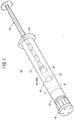
Fig. 1 is a perspective view of a prefilled syringe according to an embodiment of the present invention. -
Fig. 2 is a cross-sectional view of the prefilled syringe according to the embodiment of the present invention. -
Fig. 3 is an enlarged view of a section A inFig. 2 . -
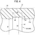
Fig. 4 is an enlarged cross-sectional view of a main part of a syringe barrel having a stepped structure according to a second configuration example. -
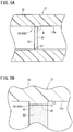
Fig. 5A is a partially omitted cross-sectional view of a syringe barrel having a stepped structure according to a third configuration example, andFig. 5B is an enlarged view of a portion B inFig. 5A . -
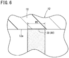
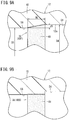
Fig. 6 is a partially omitted cross-sectional view of a syringe barrel having a scale formed using embossment. -
Fig. 7A is a partially omitted cross-sectional view of a syringe barrel having a stepped structure according to a fourth configuration example, andFig. 7B is a partially omitted cross-sectional view of a syringe barrel having a stepped structure according to a fifth configuration example. -
Fig. 8 is a cross-sectional view of a syringe barrel having a stepped structure according to a sixth configuration example. -
Fig. 9A is an enlarged cross-sectional view of a section C inFig. 8 , andFig. 9B is an enlarged cross-sectional view of a main part of a syringe barrel having a stepped structure according to a seventh configuration example. -
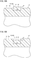
Fig. 10A is an enlarged cross-sectional view of a main part of a syringe barrel having a stepped structure according to an eighth configuration example, andFig. 10B is an enlarged cross-sectional view of a main part of a syringe barrel having a stepped structure according to a ninth configuration example. -
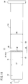
Fig. 11 is an external view of a syringe barrel having a stepped structure according to a tenth configuration example. - Hereinafter, preferred embodiments of a syringe barrel and a prefilled syringe according to the present invention will be described with reference to the accompanying drawings.
- A prefilled
syringe 10 according to the present embodiment illustrated inFigs. 1 and2 includes, as main components, asyringe barrel 12 made of a hollow body provided with a tubulardistal portion 20; acap 14 sealing the tubulardistal portion 20 of thebarrel 12, agasket 16 slidably inserted inside thebarrel 12, and a drug solution M filling aliquid chamber 17 formed by thebarrel 12 and thegasket 16. Hereinafter, thesyringe barrel 12 will be simply referred to as the "barrel 12". - In
Fig. 2 , thebarrel 12 includes: abody portion 18 having a substantially cylindrical shape and having a proximal-end opening portion 19 formed at a proximal end thereof, the tubulardistal portion 20 disposed at a distal end of thebody portion 18, alock adapter 22 provided outside the tubulardistal portion 20, and aflange 24 formed to protrude radially outward from the proximal end of thebody portion 18. - In the illustrated
barrel 12, thebody portion 18, the tubulardistal portion 20, thelock adapter 22, and theflange 24 are integrally molded. Thebarrel 12 can be manufactured, for example, by injection-molding. - The
gasket 16 is inserted into thebarrel 12 through a proximalend opening portion 19. The proximal end side of thebarrel 12 is sealed by thegasket 16 in a liquid-tight manner, and the drug solution M is sealed in thebarrel 12. - The
gasket 16 is made of an elastic material such as a rubber material. An outer circumferential portion of thegasket 16 is in liquid-tight contact with an innercircumferential surface 12a of thebarrel 12 and is arranged to be slidable inside thebarrel 12. A distal end portion of theplunger 26 is connected to thegasket 16. As the user presses theplunger 26 in a distal end direction, thegasket 16 slides in the distal end direction inside thebarrel 12. Incidentally, theplunger 26 may be connected to thegasket 16 at the time of administering the drug solution M to a patient. In addition, theplunger 26 is preferably capable of pressing thegasket 16 in the distal end direction, and may be configured to simply abut on thegasket 16 without being connected to thegasket 16. - As illustrated in
Fig. 2 , the tubulardistal portion 20 is reduced in diameter from the center of the distal end of thebody portion 18 with respect to thebarrel 12 and extends in the distal end direction. As illustrated inFig. 2 , the tubulardistal portion 20 has aliquid passage 27 communicating with theliquid chamber 17 in thebarrel 12 and passing through the tubulardistal portion 20 in the axial direction. - A needle unit (not illustrated) can be attached to and detached from the tubular
distal portion 20 in a state where thecap 14 is detached from the tubulardistal portion 20. The needle unit includes a needle body having a needle tip and a needle hub having a protrusion fixed to a proximal end portion of the needle body and protruding outward. The tubulardistal portion 20 can be tapered to be fit to an inner circumferential portion of the needle hub. At the time of use of theprefilled syringe 10, thecap 14 is unplugged (removed from the tubulardistal portion 20 and the lock adapter 22), and the needle hub of the needle unit is connected to the tubulardistal portion 20 and thelock adapter 22 instead. - The
lock adapter 22 illustrated in this example is configured in a substantially hollow cylindrical shape that extends in the distal end direction from the distal end of thebody portion 18 and surrounds the tubulardistal portion 20. Afemale screw portion 28 is formed on an inner circumferential surface of thelock adapter 22. Thefemale screw portion 28 is detachably screwed with amale screw portion 30 disposed at thecap 14 in a mounted state of thecap 14. Thefemale screw portion 28 can be engaged with the protrusion disposed at the needle hub of the needle unit described above in a state where thecap 14 is detached from thebarrel 12. - Incidentally, the
lock adapter 22 illustrated in this example may be integrally formed at a proximal end portion of the tubulardistal portion 20. Thelock adapter 22 may be a member that is configured as a separate part from thebody portion 18 and the tubulardistal portion 20 and fixed to thebarrel 12 or the tubulardistal portion 20. - The
barrel 12 is made of a resin having a total light transmittance of 80% or more in the measurement method according to ASTM-D 1003. As a result, thebarrel 12 has high transparency, and the visibility of the drug solution M filling theliquid chamber 17 can be sufficiently secured. Examples of such a resin include a cyclic olefin polymer, a cyclic olefin copolymer, polycarbonate, and the like. Incidentally, thebarrel 12 is preferably made of a resin having a total light transmittance of 90% or more in the measurement method according to ASTM-D 1003 in order to make the drug solution M filling theliquid chamber 17 easily visible. - In addition, a thickness of a side wall of the
body portion 18 of thebarrel 12 is preferably in a range of 1.5 to 2.5 mm. As a result, it is possible to suppress the sink mark at the time of injection-molding of thebarrel 12 and to suppress the gas permeability at the side wall of thebody portion 18 to be low. Since the gas permeability at the side wall of thebody portion 18 is suppressed to be low, moisture evaporation from the drug solution M filling theliquid chamber 17 is suppressed, and it is possible to prevent the sterilizing gas from passing through the side wall of thebody portion 18 and affecting the drug solution M when sterilizing the outer surface of theprefilled syringe 10 filled with the drug solution M with the sterilizing gas such as a hydrogen peroxide or ethylene oxide gas. - The
cap 14 is detachably attached to the tubulardistal portion 20, and seals a distal end opening portion of the tubulardistal portion 20. Thecap 14 in this illustrated example is configured to be attachable to and detachable from the tubulardistal portion 20. Thecap 14 is in liquid-tight contact with a distal end surface of the tubulardistal portion 20 in a state where thecap 14 is mounted to the tubulardistal portion 20. As a result, the drug solution M does not leak out of thecap 14. - As illustrated in
Fig. 2 , ascale 38 which is visible from the outside of thebarrel 12 is disposed at the innercircumferential surface 12a of the barrel 12 (the body portion 18). Thescale 38 is used as a mark at the time of aligning thegasket 16 so as to adjust the amount of the drug solution M in thebarrel 12 to a desired dose for a patient by advancing thegasket 16. - Specifically, the
scale 38 is formed using a steppedstructure 40A disposed at the innercircumferential surface 12a of the barrel 12 (the body portion 18) in the present embodiment. As illustrated inFig. 3 , the steppedstructure 40A has anannular protrusion 42 that protrudes radially inward from the innercircumferential surface 12a of thebarrel 12. Since the way of refraction of light in an edge portion of theprotrusion 42 forming the steppedstructure 40A differs from the other parts, the portion of theprotrusion 42 appears as a line along the circumferential direction of thebarrel 12 when thebarrel 12 having transparency is viewed from the outside. Therefore, theprotrusion 42 functions as the scale. - In the
prefilled syringe 10 in the initial state illustrated inFig. 2 , thebarrel 12 is filled with the drug solution M in an amount larger than a dose to the patient. Therefore, the distal end portion of thegasket 16 is positioned closer to the proximal end side than theprotrusion 42 forming the steppedstructure 40A in theprefilled syringe 10 in the initial state. As illustrated inFig. 3 , an innercircumferential surface 43 of theprotrusion 42 is parallel to the axial direction of thebarrel 12. The innercircumferential surface 43 of theprotrusion 42 may be inclined with respect to the axial direction of thebarrel 12. - An inner diameter D2 of the
protrusion 42 is smaller than an inner diameter D1 of the innercircumferential surface 12a of the portion where theprotrusion 42 is not provided (the innercircumferential surface 12a axially adjacent to the protrusion 42). Therefore, a step height d1 (protrusion height of the protrusion 42) of the steppedstructure 40A is (D1 - D2)/2. In thebarrel 12, the step height d1 is set to be 0.001 to 0.15 mm. When the step height d1 is 0.001 mm or more, good visibility as thescale 38 can be obtained. In addition, as the step height d1 is 0.15 mm or less, it is possible to suppress a sliding resistance of thegasket 16 from increasing in the process of advancing thegasket 16 inside thebarrel 12, and further, it is possible to sufficiently secure liquid tightness when thegasket 16 gets over theprotrusion 42. The step height d1 is preferably set to be 0.01 to 0.1 mm, and more preferably set to be 0.01 to 0.03 mm. - In addition, an axial width W1 of the
protrusion 42, that is, an axial width of thescale 38 is set to be 0.1 to 0.5 mm. As the axial width of thescale 38 is 0.1 mm or more, good visibility as thescale 38 can be obtained. In addition, since the axial width of thescale 38 is 0.5 mm or less, it is possible to suppress a variation in the liquid amount of the drug solution M when the gasket is aligned with thescale 38. The axial width of thescale 38 is preferably set to be 0.2 to 0.4 mm. - Next, operations and effects of the
syringe barrel 12 and theprefilled syringe 10 configured as described above will be described. - At the time of use of the
prefilled syringe 10, a user such as a doctor and a nurse first removes thecap 14 from thebarrel 12 to expose the tubulardistal portion 20, and mounts the above-described needle unit to the tubulardistal portion 20. - Next, the user advances the
gasket 16 so as to adjust the amount of the drug solution M in thebarrel 12 to the desired dose to the patient while removing air inside thebarrel 12. Specifically, the user presses theplunger 26 in the distal end direction to advance thegasket 16 connected to the distal end of theplunger 26. As thegasket 16 advances, the drug solution M is discharged from the distal end opening portion of the tubulardistal portion 20. - In this case, the
scale 38, formed using the steppedstructure 40A having theprotrusion 42, is disposed at the innercircumferential surface 12a of thebarrel 12. Therefore, it is possible to adjust the amount of the drug solution M in thebarrel 12 to a desired dose by advancing thegasket 16 such that the position of the distal end portion of thegasket 16 is aligned to the position of the scale 38 (the protrusion 42). - Next, the user punctures the patient with the needle body of the needle unit connected to the
barrel 12, and moves theplunger 26 in the distal end direction to administer the drug solution M into a body of the patient. - As described above, the
scale 38 disposed at the innercircumferential surface 12a of thebarrel 12 is formed using the steppedstructure 40A having a height in a predetermined range in thebarrel 12 of theprefilled syringe 10 according to the present embodiment. The above steppedstructure 40A is conspicuous as thescale 38 even when being provided in thebarrel 12 made of highly transparent resin. Therefore, thebarrel 12 including the high-visibility scale 38 is provided. In addition, since only thesingle scale 38 is provided in the axial direction of thebarrel 12, thescale 38 is more likely to be conspicuous. - In the present embodiment, since the stepped
structure 40A is disposed at the innercircumferential surface 12a of thebarrel 12, it is difficult for thegasket 16 and the position of thescale 38 to visually deviate from each other when viewed from the outside of thebarrel 12, and it is possible to easily align thegasket 16 to the position of thescale 38. - In the present embodiment, the stepped
structure 40A has theprotrusion 42 that protrudes radially inward from the innercircumferential surface 12a of thebarrel 12. With this configuration, the steppedstructure 40A functioning as the scale can be provided with a simple structure. - In the present embodiment, the
protrusion 42 forming the steppedstructure 40A is formed in an annular shape extending in the circumferential direction of thebarrel 12. With this configuration, the steppedstructure 40A continues circumferentially one round, and thus, it is possible to improve the visibility as the scale. - The concavo-convex shape to provide the
scale 38 visible from the outside of thebarrel 12 is not limited to the steppedstructure 40A having theprotrusion 42 protruding from the innercircumferential surface 12a of thebody portion 18. Therefore, configurations illustrated inFig. 4 to Fig. 11 may be adopted in thebarrel 12 instead of the steppedstructure 40A described above. - A stepped
structure 40B illustrated inFig. 4 has anannular groove 46 recessed radially outward with respect to the innercircumferential surface 12a of thebarrel 12. Therefore, an inner diameter D3 of thegroove 46 is larger than the inner diameter D1 of the innercircumferential surface 12a of the portion where thegroove 46 is not provided. An inner circumferential surface 47 (a surface forming a bottom of the groove 46) of thegroove 46 in the illustrated example is parallel to the axial direction of thebarrel 12. An innercircumferential surface 47 of thegroove 46 may be inclined with respect to the axial direction of thebarrel 12. A setting range of a step height d2 (a depth of the groove 46) of the steppedstructure 40B is the same as a setting range of the step height d1 of the steppedstructure 40A described above. A setting range of an axial width W2 of thegroove 46 may be the same as a setting range of the axial width W1 (seeFig. 3 ) of theprotrusion 42 described above. - Even with the above stepped
structure 40B, thescale 38 with high visibility can be provided with a simple configuration. In addition, the steppedstructure 40B can also provide the same operations and effects as those of the steppedstructure 40A described above. - The
scale 38 illustrated inFigs. 5A and 5B is formed by a steppedstructure 40C having embossment 48. In this steppedstructure 40C, the embossment 48 (a rough surface due to fine irregularities) is formed on the innercircumferential surface 43 of theprotrusion 42 in the steppedstructure 40A described above. A setting range of a step height d3 of the steppedstructure 40C (a height of theprotrusion 42 on which theembossment 48 is formed) is the same as the setting range of the step height d1 (seeFig. 3 ) of the steppedstructure 40A described above. Theembossment 48 is formed in an annular shape extending around the entire circumference of the innercircumferential surface 43 of theprotrusion 42. In addition, theembossment 48 may be formed at a plurality of locations at intervals in the circumferential direction on the innercircumferential surface 43 of theprotrusion 42. - When the
barrel 12 is formed by injection-molding, fine irregularities corresponding to theembossment 48 are formed on a surface of a core pin forming an inner mold of an injection-molding die, and such a core pin is used to perform the injection-molding of thebarrel 12 so that it is possible to mold thebarrel 12 with theembossment 48 on the inner circumferential surface. Examples of a method of providing the fine irregularities on the surface of the core pin may include chemical treatment by etching, sand blasting, polishing treatment, and the like. Incidentally, the core pin surface is exposed at the time of processing, the fine irregularities are easily formed thereon. In addition, the fine irregularities on the surface of the core pin do not interfere with an outer circumferential surface of thebarrel 12 during the injection-molding of thebarrel 12, and thus, thebarrel 12 does not remain in an outer mold for injection-molding, that is, does not cause so-called cavity remnants. - According to the above stepped
structure 40C, a difference in light transmittance between thebody portion 18 of a part where theembossment 48 is provided and thebody portion 18 of a part where theembossment 48 is not provided becomes large, and thus, it is possible to improve the visibility as thescale 38. In addition, the steppedstructure 40C can also provide the same operations and effects as those of the steppedstructure 40A described above. - In
Fig. 5B , theprotrusion 42 may be eliminated and theembossment 48 may be formed substantially without a step on the innercircumferential surface 12a of thebarrel 12. That is, thescale 38 may be formed only by theembossment 48 as illustrated inFig. 6 . The innercircumferential surface 12a of thebarrel 12 has substantially the same inner diameter in an axial range in which thegasket 16 slides inside thebody portion 18 when using theprefilled syringe 10 in which theliquid chamber 17 formed by thebarrel 12 and thegasket 16 is filled with the drug solution M. A setting range of an axial width W3 of theembossment 48 may be the same as the setting range (seeFig. 3 ) of the axial width W1 of theprotrusion 42 described above. - Even with the configuration of
Fig. 6 , thescale 38 with high visibility is obtained. In addition, there is substantially no step in a sliding range of thegasket 16 at the time of use, and thus, it is possible to suppress an increase in a sliding resistance of thegasket 16 and to suppress a decrease in liquid tightness when thegasket 16 passes through thescale 38. - The stepped
structure 40D forming thescale 38 illustrated inFig. 7A has a plurality ofprotrusions 50 provided in the innercircumferential surface 12a of thebarrel 12 at intervals in the circumferential direction. A setting range of the step height d4 (a height of the protrusion 50) of the steppedstructure 40D is the same as the setting range of the step height d1 (seeFig. 3 ) of the steppedstructure 40A described above. A setting range of the axial width W4 of theprotrusion 50 may be the same as the setting range of the axial width W1 (seeFig. 3 ) of theprotrusion 42 described above. Even if the steppedstructure 40D has a circumferentially discontinuous configuration in this manner, the function as thescale 38 can be sufficiently exhibited. Incidentally, a plurality of grooves may be disposed at intervals in the circumferential direction on the innercircumferential surface 12a of thebarrel 12 instead of the plurality ofprotrusions 50. - A stepped
structure 40E forming thescale 38 illustrated inFig. 7B is obtained by addingembossment 48 to each of inner surfaces of the plurality ofprotrusions 50 in the steppedstructure 40D illustrated inFig. 7A . By adding theembossment 48 as described above, it is possible to improve the visibility as a scale. - A stepped
structure 40F forming thescale 38 illustrated inFig. 8 is formed using an inner diameter difference of thebarrel 12. Specifically, the innercircumferential surface 12a of thebarrel 12 has a large-diameter portion 54 extending in the axial direction and a small-diameter portion 56 extending in the axial direction and having a smaller inner diameter than the large-diameter portion 54. InFig. 7 , the small-diameter portion 56 is formed to be closer to the distal end side than the large-diameter portion 54. - As illustrated in
Fig. 9A , a steppedstructure 40F is configured using a difference in inner diameter between the large-diameter portion 54 and the small-diameter portion 56. A step height d5 of the steppedstructure 40F is a half of a difference between an inner diameter D4 of thelarge diameter portion 54 and an inner diameter D5 of thesmall diameter portion 56. A setting range of the step height d5 of the steppedstructure 40F is the same as the setting range of the step height d1 (seeFig. 3 ) of the steppedstructure 40A described above. - In
Fig. 9A , theembossment 48 is formed on an inner circumferential surface of a proximal end portion of the small-diameter portion 56. Theembossment 48 is formed in an annular shape extending around the entire circumference in the circumferential direction. A setting range of an axial width W5 of theembossment 48 may be the same as the setting range of the axial width W1 (seeFig. 3 ) of theprotrusion 42 described above. In this manner, the steppedstructure 40F functioning as thescale 38 can be easily constructed by providing the inner diameter difference on the innercircumferential surface 12a of thebarrel 12 and adding theembossment 48. - In addition, the inner circumferential surface of the proximal end portion of the small-
diameter portion 56 is formed in a tapered shape increasing in diameter toward the proximal end direction, and theembossment 48 is formed on such a tapered inner circumferential surface. With this configuration, it is possible to suitably maintain the liquid tightness and the slidability of thegasket 16 when thegasket 16 moves from the large-diameter portion 54 to the small-diameter portion 56 in the process of advancing the gasket 16 (seeFig. 2 ) while improving the visibility as thescale 38. - The
embossment 48 may be formed at a plurality of locations at intervals in the circumferential direction. The small-diameter portion 56 may be formed on the proximal end side of the large-diameter portion 54. Similarly to a steppedstructure 40G forming thescale 38 illustrated inFig. 9B , the inner circumferential surface of the proximal end portion of the small-diameter portion 56 may be formed in a straight shape having an approximately constant inner diameter in the axial direction. - A stepped
structure 40H forming thescale 38 illustrated inFig. 10A is disposed at an outercircumferential surface 12b of the barrel 12 (the body portion 18). Specifically, the steppedstructure 40H has aprotrusion 60 protruding radially outward from the outercircumferential surface 12b of thebarrel 12. Theprotrusion 60 is formed in an annular shape extending in the entire circumference in the circumferential direction. A plurality of theprotrusions 60 may be formed at intervals in the circumferential direction. - A setting range of a step height d6 (a protruding height of the protrusion 60) of the stepped
structure 40H is the same as the setting range of the step height d1 (seeFig. 3 ) of the steppedstructure 40A. As a result, good visibility as thescale 38 can be obtained, and the steppedstructure 40H is prevented from being an obstacle in a manufacturing process (for example, interfering conveyance of thebarrel 12 by a feeder or the like). A setting range of an axial width W6 of theprotrusion 60 may be the same as the setting range of the axial width W1 (seeFig. 3 ) of theprotrusion 42 described above. Embossment may be formed on anouter surface 61 of theprotrusion 60 in order to make thescale 38 easily visible. - A stepped
structure 401 forming thescale 38 illustrated inFig. 10B has agroove 62 recessed radially inward from the outercircumferential surface 12b of thebarrel 12. Thegroove 62 is formed in an annular shape extending in the entire circumference in the circumferential direction. A plurality of thegrooves 62 may be formed at intervals in the circumferential direction. A setting range of a step height d7 (a depth of the groove 62) of the steppedstructure 401 is the same as the setting range of the step height d2 (seeFig. 4 ) of the steppedstructure 40B. As a result, good visibility as thescale 38 can be obtained, and the steppedstructure 401 is prevented from being an obstacle in the manufacturing process. A setting range of an axial width W7 of thegroove 62 may be the same as the setting range of the axial width W1 (seeFig. 3 ) of theprotrusion 42 described above. Embossment may be formed on aninner surface 63 of the groove 62 (a surface forming the bottom portion of the groove 62) in order to make thescale 38 easily visible. - A stepped
structure 40J forming thescale 38 illustrated inFig. 11 is formed using an outer diameter difference of the outercircumferential surface 12b of the barrel 12 (the body portion 18). Specifically, the outercircumferential surface 12b of thebarrel 12 has a large-diameter portion 64 extending in the axial direction and a small-diameter portion 66 extending in the axial direction and having a smaller inner diameter than the large-diameter portion 64, and the steppedstructure 40J is formed using an outer diameter difference between the large-diameter portion 64 and the small-diameter portion 66. The small-diameter portion 66 is formed to be closer to the distal end side than the large-diameter portion 64. - A step height d8 of the stepped
structure 40J is a half of a difference between an outer diameter D6 of the large-diameter portion 64 and an outer diameter D7 of the small-diameter portion 66. A setting range of the step height d8 of the steppedstructure 40J is the same as the setting range of the step height d1 (seeFig. 3 ) of the steppedstructure 40A described above. - In
Fig. 11 , theembossment 48 is formed on an outer circumferential surface of a distal end portion of the large-diameter portion 64. Theembossment 48 is formed in an annular shape extending around the entire circumference in the circumferential direction. A setting range of an axial width W8 of theembossment 48 may be the same as the setting range of the axial width W1 (seeFig. 3 ) of theprotrusion 42 described above. In this manner, the steppedstructure 40J functioning as thescale 38 can be easily constructed by providing the outer diameter difference on the outercircumferential surface 12b of thebarrel 12 and adding theembossment 48. - In addition, the outer circumferential surface of the distal end portion of the large-
diameter portion 64 is formed in a tapered shape decreasing in diameter in the distal end direction, and theembossment 48 is formed on such a tapered outer circumferential surface. With this configuration, when thebarrel 12 is formed by injection-molding, it is unnecessary to split an outer mold for injection-molding into split molds in order to provide the steppedstructure 40J. Thus, it is possible to suppress complication of a metal mold structure accompanying provision of the steppedstructure 40J. - Incidentally, the outer circumferential surface of the distal end portion of the large-
diameter portion 64 may be formed in a straight shape having an outer diameter substantially constant in the axial direction in thebarrel 12 illustrated inFig. 11 . In this case, it is preferable that theembossment 48 be formed on the outer circumferential surface of the distal end portion of the large-diameter portion 64 or an outer circumferential surface of a proximal end portion of the small-diameter portion 66. - The application of the
barrel 12 provided with thescale 38 is not limited to theprefilled syringe 10, but may be applied to an injector in a mode of being filled with the drug solution M after provision of a product. - The present invention is not limited to the above-described embodiments, and various modifications can be made within a scope not departing from a gist of the present invention.
Claims (11)
- A syringe barrel (12) comprising a hollow body portion (18) that is configured such that a gasket (16) is slidably insertable therein,
wherein the syringe barrel (12) is made of a resin that has a total light transmittance of 80% or more in a measurement method according to ASTM-D1003,
wherein a scale (38) is disposed at an inner circumferential surface (12a) or an outer circumferential surface (12b) of the body portion (18), the scale being visible from an outside of the syringe barrel (12) and being configured to indicate a liquid amount, and
wherein the scale (38) is formed by a stepped structure (40A to 40J) having a step height in a range of 0.001 to 0.15 mm in a radial direction, or by an embossment (48). - The syringe barrel (12) according to claim 1, wherein
the stepped structure (40A to 40G) is disposed at the inner circumferential surface (12a). - The syringe barrel (12) according to claim 1 or 2, wherein,
the scale (38) is formed in an annular shape that extends in a circumferential direction of the body portion (18) . - The syringe barrel (12) according to claim 1 or 2, wherein
a plurality of the scales (38) is disposed at intervals in a circumferential direction of the body portion (18). - The syringe barrel (12) according to any one of claims 1 to 4, wherein
the stepped structure (40A, 40C, 40D, 40H) comprises a protrusion (42, 50, 60) that protrudes radially from the inner circumferential surface (12a) or the outer circumferential surface (12b). - The syringe barrel (12) according to any one of claims 1 to 4, wherein
the stepped structure (40B, 401) comprises a groove (46, 62) that is recessed radially with respect to the inner circumferential surface (12a) or the outer circumferential surface (12b). - The syringe barrel (12) according to claim 1, wherein
the inner circumferential surface (12a) or the outer circumferential surface (12b) comprises: a large-diameter portion (54, 64) extending in an axial direction; and a small-diameter portion (56, 66) extending in the axial direction and having a smaller diameter than that of the large-diameter portion (54, 64), and
wherein the stepped structure (40F, 40J) is formed by a change in diameter between the large-diameter portion (54, 64) and the small-diameter portion (56, 66). - The syringe barrel (12) according to any one of claims 1 to 7, wherein
an axial width of the scale (38) is set to be 0.1 to 0.5 mm. - The syringe barrel (12) according to claim 1, wherein
the stepped structure (40C, 40E) comprises a protrusion (42, 50) that protrudes radially from the inner circumferential surface (12a) of the body portion (18), and
wherein the embossment (48) is formed on the inner circumferential surface (12a) of the protrusions (42, 50). - The syringe barrel (12) according to claim 1, wherein
the scale (38) is formed on the inner circumferential surface (12a) of the body portion (18) and is formed by the embossment (48), and
wherein the inner circumferential surface (12a) of the body portion (18) comprises a substantially constant inner diameter in an axial range in which the gasket (16) slides in the body portion (18) when using a prefilled syringe (10) including a drug solution (M) that is filled in a liquid chamber (17) formed by the syringe barrel (12) and the gasket (16). - A prefilled syringe (10) comprising:the syringe barrel (12) according to any one of claims 1 to 10;a gasket (16) that is slidably inserted inside the syringe barrel (12);a plunger (26) that is configured to press the gasket (16) in a distal end direction; anda drug solution (M) that is filled in a liquid chamber (17) formed by the syringe barrel (12) and the gasket (16).
Applications Claiming Priority (2)
| Application Number | Priority Date | Filing Date | Title |
|---|---|---|---|
| JP2016086947 | 2016-04-25 | ||
| PCT/JP2017/016389 WO2017188256A1 (en) | 2016-04-25 | 2017-04-25 | Syringe barrel and pre-filled syringe |
Publications (4)
| Publication Number | Publication Date |
|---|---|
| EP3453417A1 true EP3453417A1 (en) | 2019-03-13 |
| EP3453417A4 EP3453417A4 (en) | 2020-03-04 |
| EP3453417B1 EP3453417B1 (en) | 2026-02-18 |
| EP3453417C0 EP3453417C0 (en) | 2026-02-18 |
Family
ID=60159702
Family Applications (2)
| Application Number | Title | Priority Date | Filing Date |
|---|---|---|---|
| EP17789549.7A Active EP3449963B1 (en) | 2016-04-25 | 2017-04-25 | Syringe barrel for pre-filled syringe, syringe system, and pre-filled syringe |
| EP17789538.0A Active EP3453417B1 (en) | 2016-04-25 | 2017-04-25 | Syringe barrel and pre-filled syringe |
Family Applications Before (1)
| Application Number | Title | Priority Date | Filing Date |
|---|---|---|---|
| EP17789549.7A Active EP3449963B1 (en) | 2016-04-25 | 2017-04-25 | Syringe barrel for pre-filled syringe, syringe system, and pre-filled syringe |
Country Status (6)
| Country | Link |
|---|---|
| US (2) | US11020530B2 (en) |
| EP (2) | EP3449963B1 (en) |
| JP (4) | JPWO2017188267A1 (en) |
| CN (2) | CN108883232A (en) |
| AU (2) | AU2017256308A1 (en) |
| WO (2) | WO2017188256A1 (en) |
Families Citing this family (12)
| Publication number | Priority date | Publication date | Assignee | Title |
|---|---|---|---|---|
| US11654240B2 (en) * | 2018-06-01 | 2023-05-23 | Becton, Dickinson And Company | Low dose syringe including an air venting system |
| JP7217003B2 (en) * | 2019-02-08 | 2023-02-02 | ナミックス株式会社 | SYRINGE FILLED WITH RESIN COMPOSITION AND METHOD FOR STORING THE SAME |
| WO2020194397A1 (en) * | 2019-03-22 | 2020-10-01 | テルモ株式会社 | Syringe cap, syringe assembly, and prefilled syringe |
| PE20240329A1 (en) | 2019-06-05 | 2024-02-27 | Regeneron Pharma | DEVICES AND METHODS FOR PRECISION DOSE ADMINISTRATION |
| EP4129360A4 (en) | 2020-03-31 | 2023-09-06 | Daikyo Seiko, LTD. | MEDICAL SYRINGE BODY AND ITS PACKAGING |
| CN112549420B (en) * | 2020-11-05 | 2022-10-25 | 山东永聚医药科技有限公司 | Preparation process of polymer prefilled syringe |
| US12649031B2 (en) | 2021-09-08 | 2026-06-09 | Regeneron Pharmaceuticals, Inc. | Methods for delivering agents with pre-filled syringes to minimize intraocular inflammation |
| AU2023225399A1 (en) * | 2022-02-25 | 2024-07-11 | Otsuka Pharmaceutical Factory, Inc. | Syringe for cryopreservation |
| WO2023176276A1 (en) * | 2022-03-14 | 2023-09-21 | テルモ株式会社 | Liquid medicine administration system |
| USD1120314S1 (en) | 2022-11-30 | 2026-03-24 | Regeneron Pharmaceuticals, Inc. | Dose delivery device |
| WO2025191949A1 (en) * | 2024-03-15 | 2025-09-18 | テルモ株式会社 | Syringe barrel and method for manufacturing syringe barrel |
| CN117942456B (en) * | 2024-03-27 | 2024-07-12 | 山东永聚医药科技股份有限公司 | Pre-filled and sealed syringe for slow-release non-Newtonian fluid preparation and preparation process thereof |
Family Cites Families (35)
| Publication number | Priority date | Publication date | Assignee | Title |
|---|---|---|---|---|
| DE2012150C3 (en) | 1970-03-14 | 1978-11-23 | Rollei-Werke Franke & Heidecke, 3300 Braunschweig | Electronic flash unit with automatic light metering for photographic purposes |
| JP3448401B2 (en) * | 1995-07-27 | 2003-09-22 | アピックヤマダ株式会社 | Molding device with mark mechanism |
| TWI245645B (en) * | 1999-09-08 | 2005-12-21 | Chugai Pharmaceutical Co Ltd | Protein solution formulations and stabilization methods thereof |
| US20020088131A1 (en) * | 1999-10-08 | 2002-07-11 | Baxa Ronald Dale | Syringe dose identification system |
| US6972006B2 (en) * | 2002-09-18 | 2005-12-06 | G6 Science Corp. | Syringe device with resistive ridges and methods of use |
| JP2004229750A (en) * | 2003-01-28 | 2004-08-19 | Nipro Corp | Method for manufacturing prefilled syringe and barrel thereof |
| US7569026B2 (en) * | 2003-10-02 | 2009-08-04 | Terumo Kabushiki Kaisha | Method of producing blood processing circuits and filter unit |
| US7677419B2 (en) * | 2004-04-21 | 2010-03-16 | Nordson Corporation | Syringes and methods of syringe manufacturing |
| JP4759232B2 (en) * | 2004-07-02 | 2011-08-31 | テルモ株式会社 | Method for manufacturing packaged prefilled syringe |
| JPWO2006059628A1 (en) | 2004-12-01 | 2008-06-05 | 中山工業株式会社 | Viscous fluid cartridge |
| US7740792B2 (en) | 2006-08-03 | 2010-06-22 | Medrad, Inc. | Methods of molding a syringe |
| DE102006047670A1 (en) * | 2006-10-09 | 2008-04-10 | Firma G.B. Boucherie N.V. | syringe body |
| DE102007014281A1 (en) | 2007-03-19 | 2008-09-25 | Schott Ag | Method for producing a multi-chamber syringe with bypass channel |
| US8529521B2 (en) * | 2007-04-23 | 2013-09-10 | Ultimed Inc. | Low-dosage syringe |
| JP2008272162A (en) | 2007-04-27 | 2008-11-13 | Ajinomoto Co Inc | Syringe label and syringe |
| JP5344252B2 (en) * | 2007-10-31 | 2013-11-20 | 株式会社大協精工 | Syringe |
| EP2249801A2 (en) * | 2008-02-07 | 2010-11-17 | Amgen Inc. | Stabilized protein compositions |
| WO2010064667A1 (en) * | 2008-12-03 | 2010-06-10 | 電気化学工業株式会社 | Syringe |
| DE102009034897A1 (en) * | 2009-07-27 | 2011-02-03 | Eppendorf Ag | Syringe for use with dosing device that is utilized for e.g. receiving liquid, has cylindrical piston running portion connected with outlet, and coupling piece arranged at upper end of syringe piston for insertion into piston receiver |
| EP2493534B1 (en) * | 2009-10-29 | 2017-04-05 | W.L. Gore & Associates, Inc. | Syringe stopper coated with expanded ptfe |
| US9878101B2 (en) * | 2010-11-12 | 2018-01-30 | Sio2 Medical Products, Inc. | Cyclic olefin polymer vessels and vessel coating methods |
| JP5325247B2 (en) | 2011-03-14 | 2013-10-23 | テルモ株式会社 | Method for manufacturing packaged prefilled syringe |
| US9155839B1 (en) * | 2011-04-13 | 2015-10-13 | Perrigo Diabetes Care, Llc | Syringe assembly including volume indicating indicia |
| KR20140075700A (en) * | 2011-10-07 | 2014-06-19 | 미츠비시 가스 가가쿠 가부시키가이샤 | Packaging container for medical use |
| JP2013132394A (en) | 2011-12-26 | 2013-07-08 | Polyplastics Co | Method for manufacturing outer cylinder for prefilled syringe, and method for manufacturing injection molding die |
| JP5658135B2 (en) | 2011-12-28 | 2015-01-21 | 住友ゴム工業株式会社 | Method for producing composite of surface-modified fluororesin film and thermoplastic resin |
| EP3653243A1 (en) | 2012-01-27 | 2020-05-20 | Michael A. Creaturo | Safety syringe and safety dose combination kit |
| US11452817B2 (en) | 2012-02-01 | 2022-09-27 | Cd Acquisitions, Llc | System for delivering medication |
| DE202012104055U1 (en) * | 2012-10-22 | 2012-11-13 | Fluoron Gmbh | Syringe for injection of a surgical gas |
| JP2014162532A (en) * | 2013-02-27 | 2014-09-08 | Menicon Co Ltd | Blister package of prefilled syringe |
| JP2014195516A (en) * | 2013-03-29 | 2014-10-16 | 株式会社ジェイ・エム・エス | Syringe |
| JP2014223149A (en) * | 2013-05-15 | 2014-12-04 | 住友ゴム工業株式会社 | Gasket for syringe |
| JP2015073635A (en) * | 2013-10-07 | 2015-04-20 | 三菱瓦斯化学株式会社 | Multilayer syringe barrel and prefilled syringe |
| US20170135900A1 (en) * | 2014-06-30 | 2017-05-18 | Taisei Kako Co., Ltd. | Pharmaceutical container and pharmaceutical formulation |
| WO2016051962A1 (en) * | 2014-10-02 | 2016-04-07 | テルモ株式会社 | Medical container for accommodating protein solution preparation therein |
-
2017
- 2017-04-25 CN CN201780022140.0A patent/CN108883232A/en active Pending
- 2017-04-25 WO PCT/JP2017/016389 patent/WO2017188256A1/en not_active Ceased
- 2017-04-25 JP JP2018514632A patent/JPWO2017188267A1/en active Pending
- 2017-04-25 EP EP17789549.7A patent/EP3449963B1/en active Active
- 2017-04-25 AU AU2017256308A patent/AU2017256308A1/en not_active Abandoned
- 2017-04-25 CN CN201780021837.6A patent/CN109069751B/en active Active
- 2017-04-25 WO PCT/JP2017/016416 patent/WO2017188267A1/en not_active Ceased
- 2017-04-25 EP EP17789538.0A patent/EP3453417B1/en active Active
- 2017-04-25 JP JP2018514625A patent/JP7155003B2/en active Active
-
2018
- 2018-10-24 US US16/169,392 patent/US11020530B2/en active Active
- 2018-10-24 US US16/169,283 patent/US11666706B2/en active Active
-
2020
- 2020-02-13 AU AU2020201033A patent/AU2020201033B2/en active Active
-
2022
- 2022-09-07 JP JP2022142040A patent/JP2022174188A/en active Pending
-
2024
- 2024-04-22 JP JP2024068930A patent/JP2024097010A/en active Pending
Also Published As
| Publication number | Publication date |
|---|---|
| WO2017188256A1 (en) | 2017-11-02 |
| CN108883232A (en) | 2018-11-23 |
| US11020530B2 (en) | 2021-06-01 |
| EP3449963A4 (en) | 2019-12-04 |
| US20190054241A1 (en) | 2019-02-21 |
| EP3453417B1 (en) | 2026-02-18 |
| US20190054240A1 (en) | 2019-02-21 |
| EP3453417A4 (en) | 2020-03-04 |
| JPWO2017188256A1 (en) | 2019-02-28 |
| EP3453417C0 (en) | 2026-02-18 |
| JP7155003B2 (en) | 2022-10-18 |
| EP3449963B1 (en) | 2023-09-27 |
| JPWO2017188267A1 (en) | 2019-02-28 |
| AU2020201033A1 (en) | 2020-03-05 |
| WO2017188267A1 (en) | 2017-11-02 |
| CN109069751B (en) | 2022-10-25 |
| EP3449963A1 (en) | 2019-03-06 |
| US11666706B2 (en) | 2023-06-06 |
| JP2022174188A (en) | 2022-11-22 |
| JP2024097010A (en) | 2024-07-17 |
| AU2020201033B2 (en) | 2022-02-17 |
| CN109069751A (en) | 2018-12-21 |
| EP3449963C0 (en) | 2023-09-27 |
| AU2017256308A1 (en) | 2018-12-06 |
Similar Documents
| Publication | Publication Date | Title |
|---|---|---|
| EP3453417B1 (en) | Syringe barrel and pre-filled syringe | |
| KR102299431B1 (en) | Syringe and syringe set | |
| CA2457186C (en) | Prefilled syringe or carpule for medicinal purposes | |
| JP5492185B2 (en) | Gasket and syringe | |
| CA2813060C (en) | Finger-grip device for medical syringe or cartridge | |
| US11638791B2 (en) | Syringe type ejection device | |
| CN101085383A (en) | Syringe with recessed nose for use with frontal attachments | |
| JPH10113394A (en) | Method of fixing catheter insertion device between cannula and chamber and device for fixing the same | |
| CN103596611A (en) | Quantitative discharge container | |
| DK162480B (en) | hypodermic syringe | |
| ITTO20130467A1 (en) | TANK FOR MEDICINE INFUSER DEVICE. | |
| CN105517604B (en) | Syringe outer cylinder, prefilled syringe and die injection moulding | |
| EP3030293A1 (en) | Luer connection adapters for syringes | |
| EP2898912B1 (en) | Drug administration instrument | |
| EP4115928A1 (en) | Syringe set, syringe, and set | |
| JP2014200504A (en) | Medicine preparation device | |
| JP3824433B2 (en) | Drug injector | |
| JP4381614B2 (en) | Manufacturing method of prefilled syringe | |
| WO2011040222A1 (en) | Hypodermic needle assembly and medicine injection device | |
| US3870044A (en) | Hypodermic syringe body structure | |
| JP6282441B2 (en) | Nozzle replaceable drug injector | |
| JP4098593B2 (en) | Container / Syringe | |
| JP2007136996A (en) | Injection mold for outer cylinder for syringe, method for manufacturing outer cylinder for syringe, outer cylinder for syringe and syringe | |
| JP7745823B2 (en) | Syringes and syringe barrels | |
| WO2017170500A1 (en) | Grip and syringe assembly |
Legal Events
| Date | Code | Title | Description |
|---|---|---|---|
| STAA | Information on the status of an ep patent application or granted ep patent |
Free format text: STATUS: THE INTERNATIONAL PUBLICATION HAS BEEN MADE |
|
| PUAI | Public reference made under article 153(3) epc to a published international application that has entered the european phase |
Free format text: ORIGINAL CODE: 0009012 |
|
| STAA | Information on the status of an ep patent application or granted ep patent |
Free format text: STATUS: REQUEST FOR EXAMINATION WAS MADE |
|
| 17P | Request for examination filed |
Effective date: 20181123 |
|
| AK | Designated contracting states |
Kind code of ref document: A1 Designated state(s): AL AT BE BG CH CY CZ DE DK EE ES FI FR GB GR HR HU IE IS IT LI LT LU LV MC MK MT NL NO PL PT RO RS SE SI SK SM TR |
|
| AX | Request for extension of the european patent |
Extension state: BA ME |
|
| DAV | Request for validation of the european patent (deleted) | ||
| DAX | Request for extension of the european patent (deleted) | ||
| A4 | Supplementary search report drawn up and despatched |
Effective date: 20200130 |
|
| RIC1 | Information provided on ipc code assigned before grant |
Ipc: A61M 5/31 20060101AFI20200124BHEP Ipc: A61M 5/28 20060101ALI20200124BHEP Ipc: A61M 5/178 20060101ALI20200124BHEP Ipc: A61M 5/00 20060101ALI20200124BHEP |
|
| STAA | Information on the status of an ep patent application or granted ep patent |
Free format text: STATUS: EXAMINATION IS IN PROGRESS |
|
| 17Q | First examination report despatched |
Effective date: 20210204 |
|
| GRAP | Despatch of communication of intention to grant a patent |
Free format text: ORIGINAL CODE: EPIDOSNIGR1 |
|
| STAA | Information on the status of an ep patent application or granted ep patent |
Free format text: STATUS: GRANT OF PATENT IS INTENDED |
|
| INTG | Intention to grant announced |
Effective date: 20250911 |
|
| GRAS | Grant fee paid |
Free format text: ORIGINAL CODE: EPIDOSNIGR3 |
|
| GRAA | (expected) grant |
Free format text: ORIGINAL CODE: 0009210 |
|
| STAA | Information on the status of an ep patent application or granted ep patent |
Free format text: STATUS: THE PATENT HAS BEEN GRANTED |
|
| AK | Designated contracting states |
Kind code of ref document: B1 Designated state(s): AL AT BE BG CH CY CZ DE DK EE ES FI FR GB GR HR HU IE IS IT LI LT LU LV MC MK MT NL NO PL PT RO RS SE SI SK SM TR |
|
| REG | Reference to a national code |
Ref country code: CH Ref legal event code: F10 Free format text: ST27 STATUS EVENT CODE: U-0-0-F10-F00 (AS PROVIDED BY THE NATIONAL OFFICE) Effective date: 20260218 Ref country code: GB Ref legal event code: FG4D |
|
| REG | Reference to a national code |
Ref country code: CH Ref legal event code: R17 Free format text: ST27 STATUS EVENT CODE: U-0-0-R10-R17 (AS PROVIDED BY THE NATIONAL OFFICE) Effective date: 20260220 |
|
| REG | Reference to a national code |
Ref country code: DE Ref legal event code: R096 Ref document number: 602017093916 Country of ref document: DE |
|
| REG | Reference to a national code |
Ref country code: IE Ref legal event code: FG4D |
|
| PGFP | Annual fee paid to national office [announced via postgrant information from national office to epo] |
Ref country code: GB Payment date: 20260325 Year of fee payment: 10 |
|
| U01 | Request for unitary effect filed |
Effective date: 20260306 |
|
| U07 | Unitary effect registered |
Designated state(s): AT BE BG DE DK EE FI FR IT LT LU LV MT NL PT RO SE SI Effective date: 20260311 |
|
| U20 | Renewal fee for the european patent with unitary effect paid |
Year of fee payment: 10 Effective date: 20260319 |
|
| REG | Reference to a national code |
Ref country code: CH Ref legal event code: U11 Free format text: ST27 STATUS EVENT CODE: U-0-0-U10-U11 (AS PROVIDED BY THE NATIONAL OFFICE) Effective date: 20260501 |
|
| PG25 | Lapsed in a contracting state [announced via postgrant information from national office to epo] |
Ref country code: RS Free format text: LAPSE BECAUSE OF FAILURE TO SUBMIT A TRANSLATION OF THE DESCRIPTION OR TO PAY THE FEE WITHIN THE PRESCRIBED TIME-LIMIT Effective date: 20260518 |
|
| PG25 | Lapsed in a contracting state [announced via postgrant information from national office to epo] |
Ref country code: ES Free format text: LAPSE BECAUSE OF FAILURE TO SUBMIT A TRANSLATION OF THE DESCRIPTION OR TO PAY THE FEE WITHIN THE PRESCRIBED TIME-LIMIT Effective date: 20260218 |
|
| PG25 | Lapsed in a contracting state [announced via postgrant information from national office to epo] |
Ref country code: PL Free format text: LAPSE BECAUSE OF FAILURE TO SUBMIT A TRANSLATION OF THE DESCRIPTION OR TO PAY THE FEE WITHIN THE PRESCRIBED TIME-LIMIT Effective date: 20260218 |
|
| PG25 | Lapsed in a contracting state [announced via postgrant information from national office to epo] |
Ref country code: GR Free format text: LAPSE BECAUSE OF FAILURE TO SUBMIT A TRANSLATION OF THE DESCRIPTION OR TO PAY THE FEE WITHIN THE PRESCRIBED TIME-LIMIT Effective date: 20260519 |
|
| PG25 | Lapsed in a contracting state [announced via postgrant information from national office to epo] |
Ref country code: NO Free format text: LAPSE BECAUSE OF FAILURE TO SUBMIT A TRANSLATION OF THE DESCRIPTION OR TO PAY THE FEE WITHIN THE PRESCRIBED TIME-LIMIT Effective date: 20260518 |
|
| PGFP | Annual fee paid to national office [announced via postgrant information from national office to epo] |
Ref country code: CH Payment date: 20260501 Year of fee payment: 10 |
|
| PG25 | Lapsed in a contracting state [announced via postgrant information from national office to epo] |
Ref country code: HR Free format text: LAPSE BECAUSE OF FAILURE TO SUBMIT A TRANSLATION OF THE DESCRIPTION OR TO PAY THE FEE WITHIN THE PRESCRIBED TIME-LIMIT Effective date: 20260218 |
|
| PG25 | Lapsed in a contracting state [announced via postgrant information from national office to epo] |
Ref country code: IS Free format text: LAPSE BECAUSE OF FAILURE TO SUBMIT A TRANSLATION OF THE DESCRIPTION OR TO PAY THE FEE WITHIN THE PRESCRIBED TIME-LIMIT Effective date: 20260618 |