WO2010064667A1 - Syringe - Google Patents
Syringe Download PDFInfo
- Publication number
- WO2010064667A1 WO2010064667A1 PCT/JP2009/070285 JP2009070285W WO2010064667A1 WO 2010064667 A1 WO2010064667 A1 WO 2010064667A1 JP 2009070285 W JP2009070285 W JP 2009070285W WO 2010064667 A1 WO2010064667 A1 WO 2010064667A1
- Authority
- WO
- WIPO (PCT)
- Prior art keywords
- barrel
- gasket
- silicone oil
- syringe
- syringe according
- Prior art date
Links
Images


Classifications
-
- A—HUMAN NECESSITIES
- A61—MEDICAL OR VETERINARY SCIENCE; HYGIENE
- A61M—DEVICES FOR INTRODUCING MEDIA INTO, OR ONTO, THE BODY; DEVICES FOR TRANSDUCING BODY MEDIA OR FOR TAKING MEDIA FROM THE BODY; DEVICES FOR PRODUCING OR ENDING SLEEP OR STUPOR
- A61M5/00—Devices for bringing media into the body in a subcutaneous, intra-vascular or intramuscular way; Accessories therefor, e.g. filling or cleaning devices, arm-rests
- A61M5/178—Syringes
- A61M5/28—Syringe ampoules or carpules, i.e. ampoules or carpules provided with a needle
-
- B—PERFORMING OPERATIONS; TRANSPORTING
- B05—SPRAYING OR ATOMISING IN GENERAL; APPLYING FLUENT MATERIALS TO SURFACES, IN GENERAL
- B05D—PROCESSES FOR APPLYING FLUENT MATERIALS TO SURFACES, IN GENERAL
- B05D7/00—Processes, other than flocking, specially adapted for applying liquids or other fluent materials to particular surfaces or for applying particular liquids or other fluent materials
- B05D7/22—Processes, other than flocking, specially adapted for applying liquids or other fluent materials to particular surfaces or for applying particular liquids or other fluent materials to internal surfaces, e.g. of tubes
-
- A—HUMAN NECESSITIES
- A61—MEDICAL OR VETERINARY SCIENCE; HYGIENE
- A61M—DEVICES FOR INTRODUCING MEDIA INTO, OR ONTO, THE BODY; DEVICES FOR TRANSDUCING BODY MEDIA OR FOR TAKING MEDIA FROM THE BODY; DEVICES FOR PRODUCING OR ENDING SLEEP OR STUPOR
- A61M5/00—Devices for bringing media into the body in a subcutaneous, intra-vascular or intramuscular way; Accessories therefor, e.g. filling or cleaning devices, arm-rests
- A61M5/178—Syringes
- A61M5/31—Details
- A61M5/3129—Syringe barrels
-
- A—HUMAN NECESSITIES
- A61—MEDICAL OR VETERINARY SCIENCE; HYGIENE
- A61M—DEVICES FOR INTRODUCING MEDIA INTO, OR ONTO, THE BODY; DEVICES FOR TRANSDUCING BODY MEDIA OR FOR TAKING MEDIA FROM THE BODY; DEVICES FOR PRODUCING OR ENDING SLEEP OR STUPOR
- A61M5/00—Devices for bringing media into the body in a subcutaneous, intra-vascular or intramuscular way; Accessories therefor, e.g. filling or cleaning devices, arm-rests
- A61M5/178—Syringes
- A61M5/31—Details
- A61M5/315—Pistons; Piston-rods; Guiding, blocking or restricting the movement of the rod or piston; Appliances on the rod for facilitating dosing ; Dosing mechanisms
- A61M5/31511—Piston or piston-rod constructions, e.g. connection of piston with piston-rod
- A61M5/31513—Piston constructions to improve sealing or sliding
-
- B—PERFORMING OPERATIONS; TRANSPORTING
- B05—SPRAYING OR ATOMISING IN GENERAL; APPLYING FLUENT MATERIALS TO SURFACES, IN GENERAL
- B05D—PROCESSES FOR APPLYING FLUENT MATERIALS TO SURFACES, IN GENERAL
- B05D1/00—Processes for applying liquids or other fluent materials
- B05D1/02—Processes for applying liquids or other fluent materials performed by spraying
-
- B—PERFORMING OPERATIONS; TRANSPORTING
- B65—CONVEYING; PACKING; STORING; HANDLING THIN OR FILAMENTARY MATERIAL
- B65B—MACHINES, APPARATUS OR DEVICES FOR, OR METHODS OF, PACKAGING ARTICLES OR MATERIALS; UNPACKING
- B65B3/00—Packaging plastic material, semiliquids, liquids or mixed solids and liquids, in individual containers or receptacles, e.g. bags, sacks, boxes, cartons, cans, or jars
- B65B3/003—Filling medical containers such as ampoules, vials, syringes or the like
- B65B3/006—Related operations, e.g. scoring ampoules
-
- B—PERFORMING OPERATIONS; TRANSPORTING
- B65—CONVEYING; PACKING; STORING; HANDLING THIN OR FILAMENTARY MATERIAL
- B65B—MACHINES, APPARATUS OR DEVICES FOR, OR METHODS OF, PACKAGING ARTICLES OR MATERIALS; UNPACKING
- B65B7/00—Closing containers or receptacles after filling
- B65B7/16—Closing semi-rigid or rigid containers or receptacles not deformed by, or not taking-up shape of, contents, e.g. boxes or cartons
- B65B7/28—Closing semi-rigid or rigid containers or receptacles not deformed by, or not taking-up shape of, contents, e.g. boxes or cartons by applying separate preformed closures, e.g. lids, covers
-
- A—HUMAN NECESSITIES
- A61—MEDICAL OR VETERINARY SCIENCE; HYGIENE
- A61M—DEVICES FOR INTRODUCING MEDIA INTO, OR ONTO, THE BODY; DEVICES FOR TRANSDUCING BODY MEDIA OR FOR TAKING MEDIA FROM THE BODY; DEVICES FOR PRODUCING OR ENDING SLEEP OR STUPOR
- A61M5/00—Devices for bringing media into the body in a subcutaneous, intra-vascular or intramuscular way; Accessories therefor, e.g. filling or cleaning devices, arm-rests
- A61M5/178—Syringes
- A61M5/31—Details
- A61M2005/3103—Leak prevention means for distal end of syringes, i.e. syringe end for mounting a needle
- A61M2005/3104—Caps for syringes without needle
-
- A—HUMAN NECESSITIES
- A61—MEDICAL OR VETERINARY SCIENCE; HYGIENE
- A61M—DEVICES FOR INTRODUCING MEDIA INTO, OR ONTO, THE BODY; DEVICES FOR TRANSDUCING BODY MEDIA OR FOR TAKING MEDIA FROM THE BODY; DEVICES FOR PRODUCING OR ENDING SLEEP OR STUPOR
- A61M5/00—Devices for bringing media into the body in a subcutaneous, intra-vascular or intramuscular way; Accessories therefor, e.g. filling or cleaning devices, arm-rests
- A61M5/178—Syringes
- A61M5/31—Details
- A61M2005/3114—Filling or refilling
-
- A—HUMAN NECESSITIES
- A61—MEDICAL OR VETERINARY SCIENCE; HYGIENE
- A61M—DEVICES FOR INTRODUCING MEDIA INTO, OR ONTO, THE BODY; DEVICES FOR TRANSDUCING BODY MEDIA OR FOR TAKING MEDIA FROM THE BODY; DEVICES FOR PRODUCING OR ENDING SLEEP OR STUPOR
- A61M5/00—Devices for bringing media into the body in a subcutaneous, intra-vascular or intramuscular way; Accessories therefor, e.g. filling or cleaning devices, arm-rests
- A61M5/178—Syringes
- A61M5/31—Details
- A61M5/3129—Syringe barrels
- A61M2005/3131—Syringe barrels specially adapted for improving sealing or sliding
-
- A—HUMAN NECESSITIES
- A61—MEDICAL OR VETERINARY SCIENCE; HYGIENE
- A61M—DEVICES FOR INTRODUCING MEDIA INTO, OR ONTO, THE BODY; DEVICES FOR TRANSDUCING BODY MEDIA OR FOR TAKING MEDIA FROM THE BODY; DEVICES FOR PRODUCING OR ENDING SLEEP OR STUPOR
- A61M2205/00—General characteristics of the apparatus
- A61M2205/33—Controlling, regulating or measuring
- A61M2205/3306—Optical measuring means
Definitions
- the present invention relates to a syringe, and more particularly to a syringe that is suitable for injection of a high-viscosity drug and excellent in visual inspection of contents, or a prefilled syringe filled with a high-viscosity drug.
- prefilled syringes pre-filled with drugs have been used for reasons such as prevention of medical errors and bacterial contamination.
- the prefilled syringe is sealed with a cap member at the front end of the barrel, filled with a drug in the barrel, sealed with a gasket at the rear end of the barrel, transported and stored in that state, and at the end of the barrel for administration
- the injection needle or administration device is attached to the side, the plunger attached to the gasket is pushed toward the tip side, and the gasket is slid within the barrel, whereby the drug is discharged from the injection needle and administered.
- prefilled syringes do not require preparation of drugs at the medical site, so that they can be administered at an accurate dose without misuse of drugs, there is no operation to transfer drugs, and hygiene is high. It has various advantages such as simplicity.
- prefilled syringes are stored and distributed in a state of being filled with a drug, it may take several years from the time the drug is filled in a production factory until the administration. For this reason, it is needless to say that long-term stability is required, but it is required to be able to visually determine the contamination of impurities during administration and to confirm the safety of the drug. Therefore, the material constituting the barrel is required to be highly transparent, and in the conventional prefilled syringe, a glass barrel that can ensure transparency is frequently used.
- silicone in the form of emulsion is applied to the inner peripheral surface of the barrel, and this is baked at a high temperature (200 to 300 ° C.) to fix the silicone.
- a high temperature 200 to 300 ° C.
- silicone oil contain fine powder silica in order to prevent the silicone oil from forming into oil droplets on the inner peripheral surface of the barrel and mixing it into the drug, and to suppress an increase in the sliding resistance of the gasket. (Patent Document 2).
- the resin barrel lubrication method including fixation requires a curing process step such as radiation irradiation as described in Patent Document 1 above, so that the production efficiency is inevitably inferior.
- Some hardeners and the like to be added may affect the human body when mixed in the medicine.
- the applied silicone oil may be dissociated from the inner peripheral surface of the barrel during filling or storage / transportation and mixed into the drug, causing turbidity. .
- the refractive index of the applied silicone oil is different from the refractive index of the drug or the synthetic resin constituting the syringe.
- the sealing plug (gasket) for a syringe described in Patent Document 3 since the surface of the rubber plug body is laminated with a resin film, the actual size of the sealing plug (gasket) for the syringe or the initial design dimension of the inner diameter of the barrel In some cases, the tolerance, which is a variation in the dimensions, increases, and there is a tendency for problems to occur in the slidability or sealing performance of the sealing plug (gasket) for the syringe with respect to the inner surface of the barrel.
- the present invention has been made in view of the above-described circumstances, and is a syringe excellent in inspection accuracy while ensuring slidability and sealing performance between a barrel and a gasket, particularly for filling a high-viscosity drug. Another object is to provide a suitable syringe.
- the present inventors sprayed silicone oil having a predetermined kinematic viscosity on the inner peripheral surface of a resin barrel so that a predetermined application amount per unit area is obtained.
- the present inventors have found that it is possible to impart properties, and to suppress dissociation / mixing of silicone oil and glare on the inner peripheral surface of the barrel.
- the syringe of the present invention has a resin barrel, a gasket slidably inserted into the barrel, a plunger attached to the gasket, and a kinematic viscosity of 500 to 100 on the inner peripheral surface of the barrel. And a silicone film formed by applying a silicone oil of 1,000 cSt at a coating amount of 5 to 50 ⁇ g per 1 cm 2 area.
- a silicone oil having a kinematic viscosity of 500 cSt or more is used as the silicone constituting the silicone film. Therefore, when the silicone oil is sprayed, the silicone oil is appropriately held without flowing on the inner peripheral surface of the barrel. The Therefore, even when silicone oil is applied in a small amount, sufficient slidability with the gasket can be ensured. Further, since the silicone oil having a kinematic viscosity of 100,000 cSt or less is used, it can be spray-coated on the inner peripheral surface of the barrel, and the silicone oil is uniformly applied so that the predetermined coating amount per unit area is obtained. It is possible.
- silicone oil having a kinematic viscosity in this range sufficient slidability is ensured between the barrel and gasket even when the amount of silicone oil applied to the inner peripheral surface of the barrel is 50 ⁇ g or less per 1 cm 2 area.
- the amount of silicone oil applied can be reduced to a small amount.
- the amount of entrainment can be kept to a very small amount. Therefore, the occurrence of turbidity due to the mixing of silicone oil is suppressed, and the cause of the turbidity of the drug in the prefilled syringe can be limited when foreign substances other than silicone oil are mixed, and visual inspection to ensure safety is possible.
- the accuracy can be substantially improved.
- silicone oil having a kinematic viscosity in the above range has a high viscosity, it is generally not easy to spray uniformly.
- uniform spraying is possible by appropriately adjusting the liquid temperature, air pressure, nozzle diameter, coating time, and the like.
- heating is performed to such an extent that silicone oil is not denatured, so that a fine mist spray can be achieved, and an extremely thin film as in the above range can be realized.
- the gasket so that the maximum outer diameter is larger than the inner diameter of the barrel and the difference between the maximum outer diameter of the gasket and the inner diameter of the barrel is 0.02 mm to 0.50 mm, the gap between the gasket and the barrel It is possible to sufficiently secure the slidability between the barrel and the gasket while suppressing the leakage of the medicine from the container and maintaining the sealing performance of the gasket.
- the “refraction angle” in the present invention means that when a prefilled syringe filled with a drug is irradiated with incident light having an optical axis perpendicular to the central axis of the barrel, the optical axis of transmitted light diffused in the same direction as the central axis is used. Represents the opening angle of.
- the transmitted light is largely refracted with the central axis as the center of curvature in the direction perpendicular to the central axis. Therefore, the refraction generated in the direction perpendicular to the central axis is largely influenced by the shape of the barrel, and cannot reflect a slight difference in the application state of the silicone oil on the inner peripheral surface of the barrel.
- the barrel is not substantially bent with respect to the central axis direction, the branch from the optical axis that occurs in the same direction as the central axis, that is, the “refraction angle” in the present invention is not easily affected by the shape of the barrel.
- the application state of silicone oil can be directly reflected.
- the refraction angle of the prefilled syringe filled with the drug is in the range of 0.1 to 0.5 °, it has been found that the risk of glare on the inner peripheral surface of the barrel is extremely low as long as a human observes it with the naked eye. .
- the prefilled syringe having the refraction angle can remarkably improve the inspection accuracy of the medicine visually.
- the medicine can be more stably accommodated in the barrel while ensuring the slidability and sealing performance between the barrel and the gasket, and the accuracy of substantial inspection of the contents is improved. Can be made. Thereby, safe and accurate operation is possible.
- the syringe according to the present invention has high utility as a medical instrument or a beauty instrument.
- FIG. 1 is a schematic view of a prefilled syringe which is a preferred embodiment of the present invention.
- the prefilled syringe 1 can basically adopt the configuration of a conventional prefilled syringe as it is, and as shown in FIG. 1, a barrel 20 having a tip opening 21 provided at the tip, and a barrel A syringe 10 having a gasket 24 slidable in a liquid-tight and air-tight manner within the inside 20 and a plunger 25 attached to the rear end of the gasket 24, and a cap member 26 that seals the tip opening 21 of the barrel 20. And a medicine 27 housed inside the syringe 10.
- a silicone film 28 formed by spraying silicone oil is provided on the inner peripheral surface of the barrel 20.
- the silicone film 28 is shown as if it had been applied with a constant thickness, but the amount of silicone oil applied to the inner peripheral surface of the barrel 20 is 5 per 1 cm 2 of area. If it is in the range of ⁇ 50 ⁇ g, the desired effect can be obtained sufficiently, and it is not necessarily uniform.
- the barrel 20 is a cylindrical body, and a distal end opening 21 for attaching an injection needle is provided at the distal end, and a finger is placed at the rear end during a drug injection operation.
- a pair of flanges 22 are provided to face each other.
- a cap member 26 which is a sealing member to be described later is attached to the distal end opening 21 of the barrel 20.
- an injection needle (not shown) may be directly attached.
- a screwing portion 23 for attaching the cap member 26 or the injection needle is provided on the outer peripheral surface of the tip opening 21.
- the barrel 20 is formed of a transparent resin material in order to allow visual inspection of the filled medicine 27.
- the material for forming the barrel 20 is not particularly limited, but for example, polystyrene, polyamide, polycarbonate, polyvinyl chloride, polyvinylidene chloride, poly- (4-methylpentene-1) in terms of light transmittance, strength, or dimensional accuracy. ), Various resins such as polyvinyl alcohol, acrylic resin, acrylonitrile-butadiene-styrene copolymer, polyester such as polyethylene terephthalate, cyclic polyolefin, and cyclic olefin copolymer.
- a cyclic olefin polymer (COP) or a cyclic olefin copolymer (COC) having particularly excellent permeability is preferable from the viewpoint of improving the efficiency and accuracy of visual inspection of contents.
- a resin is a thermoplastic saturated norbornene-based resin composition marketed under the Zeonex (registered trademark) by Nippon Zeon Co., Ltd., and is incompatible with the thermoplastic saturated norbornene-based resin. What disperse
- the gasket 24 is not particularly limited in material, but is preferably formed of an elastic body such as rubber or a thermoplastic elastomer in order to maintain airtightness. Among these, it is particularly preferable to use butyl rubber having a small dimensional change in autoclave sterilization as a main raw material. As the butyl rubber, halogenated butyl rubber that has been chlorinated or brominated to improve crosslinkability, adhesion, and the like can also be used. However, it is not particularly limited as long as it can be used as a medical instrument and has been conventionally used as a material for forming a syringe gasket. Further, the surface material of the gasket is not particularly limited.
- a material that has not been surface-treated with a tetrafluoroethylene resin film or an ultrahigh molecular weight polyethylene film is preferable.
- silicone oil can be applied to the gasket surface.
- the gasket 24 has a plurality of peak portions (ring-shaped convex portions) as shown in FIG. Since the sliding area between the gasket 24 and the barrel 20 can be reduced by having a plurality of peaks and valleys (ring-shaped recesses) provided therebetween, the gasket 24 and the barrel 20 can be reduced. The sliding resistance between them can be reduced. In addition, by having a plurality of peak portions and valley portions provided therebetween, the drug 27 can be dammed in a plurality of stages, and the drug 27 leaks from the gap between the gasket 24 and the barrel 20. This can be suppressed.
- peak portions ring-shaped convex portions
- the maximum outer diameter of the gasket 24 corresponds to the outer diameter of the first peak portion closest to the tip portion among the plurality of peak portions. This is because the first peak closest to the tip of the plurality of peaks of the gasket 24 is actually in direct contact with the drug 27, so that the outer diameter of the peak is maximized. This is because the medicine 27 can be effectively prevented from leaking from the gaps between the two.
- the maximum outer diameter of the gasket 24 needs to be larger than the inner diameter of the barrel 20. As described above, since the maximum outer diameter of the gasket 24 is larger than the inner diameter of the barrel 20, the medicine 27 can be prevented from leaking from the gap between the gasket 24 and the barrel 20, and the sealing performance of the gasket 24 is maintained. be able to.
- the difference between the maximum outer diameter of the gasket 24 and the inner diameter of the barrel 20 needs to be 0.02 mm or more and 0.50 mm or less.
- the difference between the maximum outer diameter of the gasket 24 and the inner diameter of the barrel 20 is 0.02 mm or more and 0.50 mm or less, so that the leakage of the drug 27 from the gap between the gasket 24 and the barrel 20 is suppressed. This is because the slidability between the barrel 20 and the gasket 24 can be sufficiently ensured while maintaining the hermetic sealability.
- the difference between the maximum outer diameter of the gasket 24 and the inner diameter of the barrel 20 is preferably 0.10 mm or more, and more preferably 0.15 mm or more. This is because the larger this difference is, the easier it is to prevent the medicine 27 from leaking from the gap between the gasket 24 and the barrel 20.
- the difference between the maximum outer diameter of the gasket 24 and the inner diameter of the barrel 20 is preferably 0.40 mm or less, and more preferably 0.35 mm or less. This is because the smaller the difference, the better the slidability between the barrel and the gasket.
- the tolerance after autoclave sterilization of the maximum outer diameter of the gasket 24 (variation in the dimensional accuracy of the actual product with respect to the design dimension) is preferably controlled to be ⁇ 0.10 mm or less, and ⁇ 0.05 mm. It is more preferable if it is managed so as to be as follows. This is because, if the variation in the dimensional accuracy of the gasket 24 is within this range, all the syringes 10 can stably ensure sufficient slidability and sealing performance of the gasket.
- the tolerance of the inner diameter of the barrel 20 (variation in the dimensional accuracy of the actual product with respect to the design dimension) is preferably controlled to be ⁇ 0.10 mm or less, and is managed to be ⁇ 0.05 mm or less. It is more preferable. This is because, if the variation in the dimensional accuracy of the barrel 20 is within this range, sufficient syringe slidability and sealing performance can be secured with most syringes 10.
- the gasket 24 has a structure in which a tetrafluoroethylene resin film or an ultrahigh molecular weight polyethylene film is laminated on the surface of the rubber plug main body, the difference between the maximum outer diameter of the gasket 24 and the inner diameter of the barrel 20 is determined. It may be difficult to fit within the range. This is because when manufacturing the gasket 24 having such a complicated laminated structure, the manufacturing process is complicated, and as a result, the variation in the actual dimension of the gasket 24 with respect to the original design dimension tends to increase. is there.
- the dimensional accuracy of the manufacturing process of both the gasket 24 and the barrel 20 is improved, or the inspection process of dimensional accuracy is strictly operated.
- the gasket structure itself can be designed in a simple shape, and the gasket manufacturing process itself can be simplified. That is, in the syringe 10 of the present embodiment, the gasket 24 that is not surface-treated with a resin film is used, and the dimensional accuracy in the manufacturing process of both the gasket 24 and the barrel 20 is further improved, or the dimensional accuracy is increased. It is preferable to manage the maximum outer diameter of the gasket 24 with high accuracy by strictly operating the inspection process.
- the plunger 25 is sufficient if it has a strength sufficient to withstand the pushing force and bending required for sliding the gasket 24 within the barrel 20, and is made of a hard plastic material such as polyethylene or polypropylene. Although it is mentioned, it is not particularly limited as long as it can be used as a medical instrument and has been conventionally used as a material for forming a plunger.
- the cap member 26 is in close contact with the tip opening 21 of the barrel 20 and hermetically seals the tip opening 21 and is made of an elastic body or hard resin such as butyl rubber, high-density polyethylene, polypropylene, polystyrene, or polyethylene terephthalate.
- an elastic body or hard resin such as butyl rubber, high-density polyethylene, polypropylene, polystyrene, or polyethylene terephthalate.
- a thing can be used, if it can be used as a medical instrument and has been conventionally used as a material for forming a cap member, it is not particularly limited.
- a female thread portion that is threadedly engaged with the threaded portion 23 formed on the outer peripheral surface of the tip opening 21 of the barrel 20 is formed on the inner peripheral surface of the cap member 26.
- the silicone oil applied to the inner peripheral surface of the barrel to form the silicone film 28 is basically polydimethylsiloxane, but polydimethylsiloxane having substituted side chains and terminals may be used as long as the lubricity is not impaired. it can. Specific examples include polymethylphenylsiloxane and polymethylhydrogensiloxane. You may mix
- the silicone oil preferably has a kinematic viscosity at 25 ° C. of 500 to 100,000 cSt, and more preferably 1,000 to 30,000 cSt. If the kinematic viscosity is 500 cSt or more, the silicone oil does not flow on the inner peripheral surface of the barrel 20 and the silicone oil is appropriately held at the spray position on the inner peripheral surface of the barrel 20, so Sufficient slidability with the gasket 24 can be ensured. Further, if the kinematic viscosity is 100,000 cSt or less, the inner peripheral surface of the barrel 20 can be applied by spraying.
- the application amount of the silicone oil constituting the silicone film 28 is preferably 5 to 50 ⁇ g, particularly 10 to 30 ⁇ g, per 1 cm 2 of the inner peripheral surface of the barrel 20. If the amount of silicone oil applied is 5 ⁇ g or more per 1 cm 2 of the inner peripheral surface of the barrel, sufficient slidability can be ensured between the barrel 20 and the gasket 24. Further, if the coating amount is 50 ⁇ g or less per 1 cm 2 of the inner peripheral surface of the barrel, the amount of entrainment can be suppressed to a very small amount even when silicone oil is entrained in the agent when the agent 27 is filled. it can. Furthermore, as long as it is observed with the naked eye, no glare is felt on the inner peripheral surface of the barrel 20.
- the silicone film 28 is formed by uniformly spraying the silicone oil having the kinematic viscosity on the inner peripheral surface of the barrel 20 using a spray system corresponding to the high viscosity liquid agent.
- the silicone oil to be applied has a high kinematic viscosity, it is necessary to appropriately adjust the liquid temperature, air pressure, nozzle diameter, application time, etc. so that the silicone oil can be uniformly applied to the inner peripheral surface of the barrel 20. is there.
- the silicone oil can be easily sprayed by heating the silicone oil especially during spraying.
- the kinematic viscosity at 25 ° C. is 500 to 100,000 cSt, particularly 1,000 to 50,000 cSt, similar to the silicone oil applied to the inner peripheral surface of the barrel.
- the kinematic viscosity is 500 cSt or more, the applied silicone oil does not flow, and the lubricating action lasts for a long time.
- kinematic viscosity is 100,000 cSt or less, it can apply
- a coating method a conventionally used method can be used. For example, a method in which silicone oil is directly put into a tank in which a gasket is placed and stirred, and a gasket is placed in water in which silicone oil is suspended. A method of stirring can be used.
- the amount of silicone oil applied to the gasket surface per unit area Even when applying silicone oil to the gasket, the coating amount in order to suppress entrainment of the silicone oil to the drug because it should be the minimum necessary, the area 1 cm 2 per 0 coating amount of the silicone oil gasket surface.
- the amount is preferably 3 mg or less, and more preferably 0.15 mg or less.
- the medicine 27 is not particularly limited as long as it can be filled in a prefilled type syringe, but the syringe 10 having the above-described configuration is particularly suitable for filling a high-viscosity medicine.
- a high-viscosity drug is filled, a high shear stress is applied to the inner peripheral surface of the barrel, so that the silicone oil applied to the inner peripheral surface of the barrel is easily caught in the drug, and as a result, turbidity is likely to occur.
- the silicone oil having the predetermined viscosity is applied to the inner peripheral surface of the barrel at the predetermined application amount per unit area, the amount of the silicone oil involved can be kept small. Therefore, it can be said that the syringe 10 having the above configuration is particularly suitable for a high-viscosity drug that is likely to become turbid at the time of filling.
- the maximum value of the extrusion pressure during sliding is higher than when the low-viscosity drug 27 is used.
- the syringe 10 having the above-described configuration is particularly suitable for a high-viscosity drug in which the maximum value of the extrusion pressure during sliding tends to be high.
- the syringe 10 having the above-described configuration can stably accommodate even a high-viscosity drug having a viscosity of about 60,000 mPa ⁇ s.
- the weight average molecular weight is 60 to Mention may be made of a 3.7% 1% aqueous solution of high molecular weight sodium hyaluronate.
- FIG. 2 is a conceptual diagram showing an aspect of an apparatus for measuring a refraction angle.
- This refraction angle measuring device uses a laser oscillation device 31 that irradiates the prefilled syringe 1 with a light beam (incident light 33) and a projection plate 32 that projects the light beam that has exited the prefilled syringe 1 (transmitted light 34).
- the laser oscillation device 31 is a device for irradiating the prefilled syringe 1 filled with a medicine with incident light 33 having an optical axis 41 perpendicular to the central axis 40 of the barrel 20.
- the wavelength of the oscillating laser is not particularly limited, and any visible light laser such as red, green, blue, and purple can be used. However, since the value of the refraction angle changes depending on the wavelength, it is necessary to measure at a constant wavelength. Therefore, it is preferable to use a general red laser having a wavelength in the range of 635 nm to 690 nm.
- the projection plate 32 is not particularly limited as long as the projection plate 32 is a flat plate having no distortion on the surface. The projection plate 32 is disposed so as to be perpendicular to the optical axis 41 of the light beam emitted from the laser oscillation device 31.
- the position of the laser oscillation device 31 is first fixed, and then the projection plate 32 is fixed so as to be perpendicular to the optical axis 41 of the light beam emitted from the laser oscillation device 31. To do. In this state, that is, in a state where the prefilled syringe 1 to be measured is not arranged, the light beam irradiated from the laser oscillation device 31 is projected onto the projection plate 32. In the case of using a laser oscillation device in which the shape of the projected image 42 is substantially circular, the diameter of the projected image 42 is the light width “A” of the incident light 33.
- the direction of the laser oscillation device is adjusted so that the minor axis direction of the ellipse matches the central axis direction of the barrel.
- the length of the minor axis of the ellipse is the light width “A” of the incident light 33.
- a laser oscillation device in which the projected image 42 has a shape other than a circle or an ellipse is not suitable for the refraction angle measurement in the present invention.
- the light width “A” of the incident light 33 is preferably 3.0 mm or less, and more preferably 2.0 mm or less, because a difference in refraction angle becomes difficult to see when the light width is increased.
- the prefilled syringe 1 that is a measurement target is disposed at a predetermined position on the optical axis 41.
- the posture of the prefilled syringe 1 is adjusted so that the central axis 40 of the prefilled syringe 1 is orthogonal to the optical axis 41.
- the prefilled syringe 1 is irradiated with light rays (incident light 33) from the laser oscillation device 31, and the transmitted light 34 emitted from the prefilled syringe 1 is projected onto the projection plate 32.
- the width “D” in the same direction as the central axis 40 of the projection image 42 projected onto the projection plate 32 and the distance “L” from the central axis 40 of the prefilled syringe 1 to the projection plate 32 are measured.
- the refraction angle is the optical axis of the transmitted light 34 diffused in the same direction as the central axis 40 when the prefilled syringe 1 filled with the medicine is irradiated with the incident light 33 of the optical axis 41 orthogonal to the central axis 40 of the barrel 20.
- the refraction angle is the light width “A” of the incident light 33 irradiated from the laser oscillation device 31, the distance “L” from the central axis 40 of the prefilled syringe 1 to the projection plate 32, and the transmission projected on the projection plate 32.
- the whole barrel 20 is formed as a single compartment and filled with a medicine.
- the barrel 20 is divided into a plurality of compartments by partitioning the inside of the barrel 20 with one or more sealing plugs. Also good. In this case, it is possible to prevent contamination and leakage of the drug more reliably, or to fill a single syringe with a plurality of drugs.
- Example 1 Silicone oil (Shin-Etsu Chemical Co., Ltd.) with a kinematic viscosity of 5,000 cSt on the inner peripheral surface of a barrel with a capacity of 5 ml, a cylinder outer diameter of 15.05 mm, a cylinder inner diameter of 12.45 mm, and a total length of 79.0 mm, which is formed mainly of COP resin.
- “KF-96-5000cs” manufactured by the company was sprayed under the following conditions so that the average coating amount was 18 ⁇ g in the range of 12 to 25 ⁇ g per cm 2 .
- thermoplastic saturated norbornene resin composition commercially available as Zeonex (registered trademark) from Nippon Zeon Co., Ltd. was used. (Silicone oil spraying conditions) Spraying time: 0.05 seconds Air pressure: 0.5 MPa Silicone oil heating temperature: 180 ° C Nozzle diameter: 1.0mm
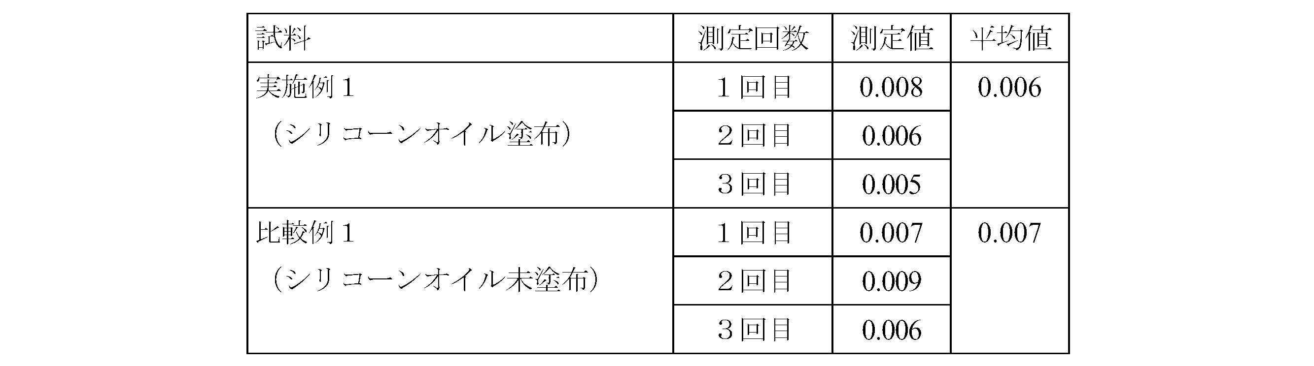
- Example 1 A barrel similar to Example 1 (Comparative Example 1) was prepared except that the silicone oil was not sprayed, and the light transmittance was compared with the barrel of Example 1 above.
- the following apparatus and method were used for the measurement of light transmittance.
- Appatus ⁇ Spectrophotometer (manufactured by Hitachi High-Technologies Corporation, model number: U-3310) ⁇ Wavelength: 660nm (Method) ⁇ Set the spectrophotometer to zero with nothing in the spectrophotometer sample chamber. • Secure the barrel in the spectrophotometer sample chamber.
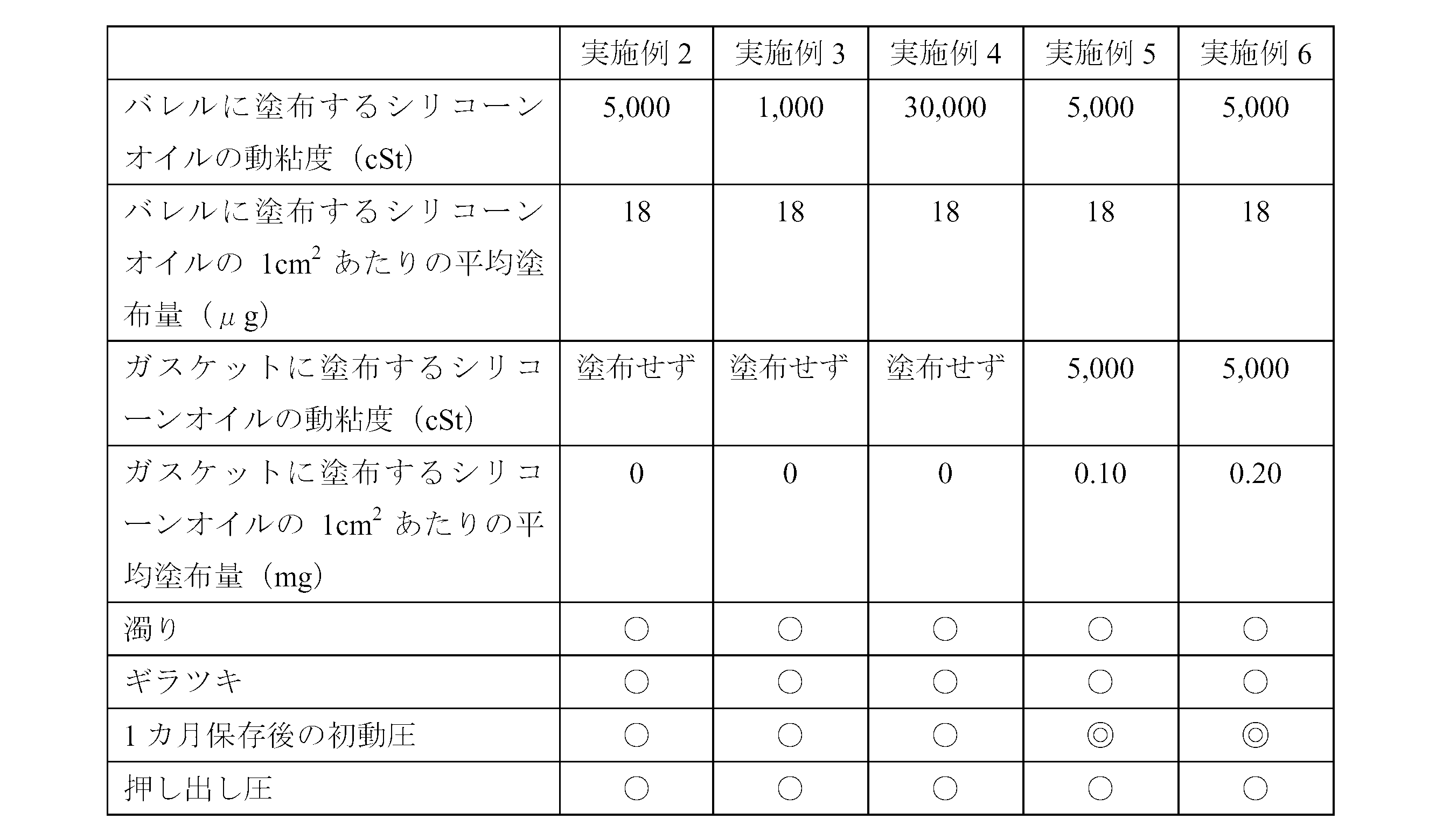
- Example 3 A barrel having a silicone film formed in the same manner as in Example 1 except that a silicone oil having a kinematic viscosity of 1,000 cSt (“KF-96-1000cs” manufactured by Shin-Etsu Chemical Co., Ltd.) was used as the silicone oil. Using this barrel, a prefilled syringe was assembled in the same manner as in Example 2.
- Example 4 A barrel formed with a silicone film was prepared in the same manner as in Example 1 except that a silicone oil having a kinematic viscosity of 30,000 cSt (“KF-96H-30,000 cs” manufactured by Shin-Etsu Chemical Co., Ltd.) was used as the silicone oil. Then, using this barrel, a prefilled syringe was assembled in the same manner as in Example 2.
- a silicone oil having a kinematic viscosity of 30,000 cSt (“KF-96H-30,000 cs” manufactured by Shin-Etsu Chemical Co., Ltd.) was used as the silicone oil.
- Example 5 Furthermore, it was decided to apply 0.1 mg of silicone oil to 1 cm 2 of the surface of the gasket. That is, a silicone oil having a kinematic viscosity of 5,000 cSt was dropped into a tank containing water in an amount of 0.13 mg per 1 cm 2 with respect to the total surface area of all gaskets, and stirred for 10 minutes to disperse. . The gasket was put into this, and it stirred for 10 minutes at 100 degreeC, blowing steam from the bottom, drained and rinsed, and sterilized by the autoclave. When the amount of silicone oil applied was confirmed by weight measurement, it was confirmed that the amount was 0.10 mg per 1 cm 2 of the gasket surface. A prefilled syringe was assembled in the same manner as in Example 2 except that this gasket was used.
- Example 6 Furthermore, it was decided to apply 0.2 mg of silicone oil to 1 cm 2 of the surface of the gasket.
- the application method was the same as in Example 5, but an amount of silicone oil of 0.26 mg per cm 2 was dropped with respect to the total surface area of all gaskets.
- the amount of silicone oil applied was confirmed in the same manner as in Example 5, it was 0.20 mg per 1 cm 2 of the gasket surface.
- a prefilled syringe was assembled in the same manner as in Example 2 except that this gasket was used.
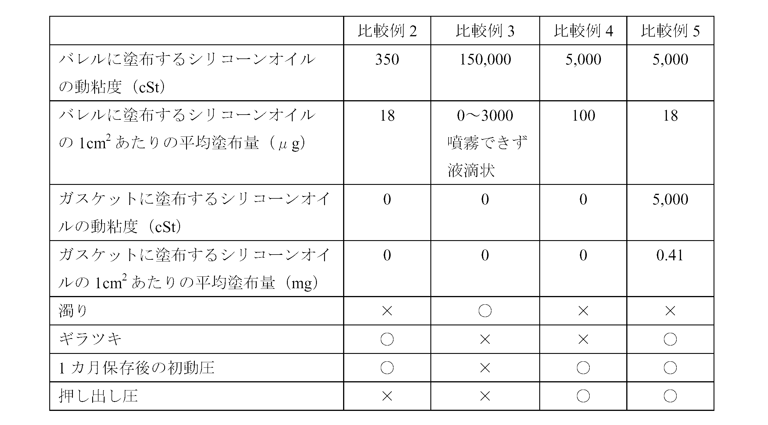
- ⁇ Comparative example 2> A barrel formed with a silicone film was prepared in the same manner as in Example 1 except that a silicone oil having a kinematic viscosity of 350 cSt (“KF-96-350cs” manufactured by Shin-Etsu Chemical Co., Ltd.) was used as the silicone oil. A prefilled syringe was assembled in the same manner as in Example 2.
- Example 3 As the silicone oil, 370 g of silicone oil having a kinematic viscosity of 300,000 cSt (“KF-96-300,000 cs” manufactured by Shin-Etsu Chemical Co., Ltd.) and silicone oil having a kinematic viscosity of 100,000 cSt (“KF- manufactured by Shin-Etsu Chemical Co., Ltd.) A barrel formed with a silicone film was prepared in the same manner as in Example 1 except that a mixed silicone oil having a kinematic viscosity of 150,000 cSt prepared by mixing 630 g with 960 g was used. A prefilled syringe was assembled in the same manner as in Example 2.
- Example 4 A barrel formed with a silicone film was prepared in the same manner as in Example 1 except that the silicone oil was sprayed so that the average coating amount per cm 2 of the silicone film was 100 ⁇ g. Using this barrel, Example 2 and Similarly, a prefilled syringe was assembled.
- ⁇ Visual evaluation> The presence or absence of turbidity in the drug and the presence or absence of glare on the inner peripheral surface of the barrel were evaluated visually by collecting five panelists composed of skilled quality inspection personnel. The results are shown in Table 2. Turbidity evaluation criteria: ⁇ (Good): No turbidity is confirmed. X (defect): Turbidity is confirmed. Glare evaluation criteria: ⁇ (Good): No glare is observed. X (defect): Glare is observed.
- ⁇ Sliding resistance evaluation> Attach an injection needle (23G ⁇ 1 1/4 Terumo) to the tip of the prefilled syringe, and use a tester (“EZ-TEST” manufactured by Shimadzu Corporation) to discharge the drug at an extrusion speed of 100 mm / min. The initial dynamic pressure and the extrusion pressure were measured. In addition, the initial dynamic pressure measurement used the sample preserve
- COP resin a thermoplastic saturated norbornene resin composition commercially available as Zeonex (registered trademark) from Nippon Zeon Co., Ltd. was used.
- tolerance control ⁇ 0.05 mm
- Air pressure 0.5 MPa
- Silicone oil heating temperature 180 ° C
- Nozzle diameter 1.0mm
- a butyl rubber gasket which is a kind of rubber material whose surface is not resin-processed, has an outer diameter of ⁇ 12.70 ⁇ 0.10 mm (first peak), ⁇ 12.0 ⁇ 0.10 mm (valley), and a total length of 10. Manufactured and inspected with tolerance control of 0 ⁇ 0.30 mm. Since this gasket uses butyl rubber, the dimensional change in autoclave sterilization is small compared to general gaskets, and it can be kept within a tolerance range of ⁇ 0.10 mm even after sterilization. is there.
- the gasket was coated with 0.1 mg of silicone oil (KF-96-5000cs manufactured by Shin-Etsu Chemical Co., Ltd.) per 1 cm 2 area.
- the syringe is basically the same as Example 7, but as a gasket, a tetrafluoroethylene resin film is laminated on the surface of butyl rubber, and the tolerance is outer diameter ⁇ 12.70 ⁇ 0.10 mm (first peak), ⁇ 12 0.0 ⁇ 0.10 mm (valley) and a total length of 10.0 ⁇ 0.30 mm were used, and syringes different in that silicone oil was not applied were prepared.
- Example 7 Comparative Example 6 how the dimension of the gasket changed before and after the autoclave.
- the gasket made of butyl rubber whose surface was not resin-processed in Example 7 hardly changed in size before and after the autoclave, and the dimensional accuracy remained within the tolerance range (data not shown).
- the gasket obtained by laminating a tetrafluoroethylene resin film on the surface of the butyl rubber of Comparative Example 6 has a large dimensional change before and after the autoclave, and the dimensional accuracy after the autoclave has an outer diameter of ⁇ 12.70 ⁇ 0.20 mm (first It was found that the peak portion was ⁇ 12.0 ⁇ 0.20 mm (valley portion) and the total length was 10.0 ⁇ 0.40 mm.
- ⁇ Comparative Example 7> Basically the same syringe as in Example 7, but with a volume of 5 ml formed with COP resin as the main component, outer diameter 15.05 ⁇ 0.1 mm, inner diameter 12.45 ⁇ 0.20 mm, total length 79.0 ⁇ Different syringes were prepared using barrels manufactured and inspected with tolerance management of 0.2 mm and flange diameter ⁇ 22.0 ⁇ 0.2 mm.
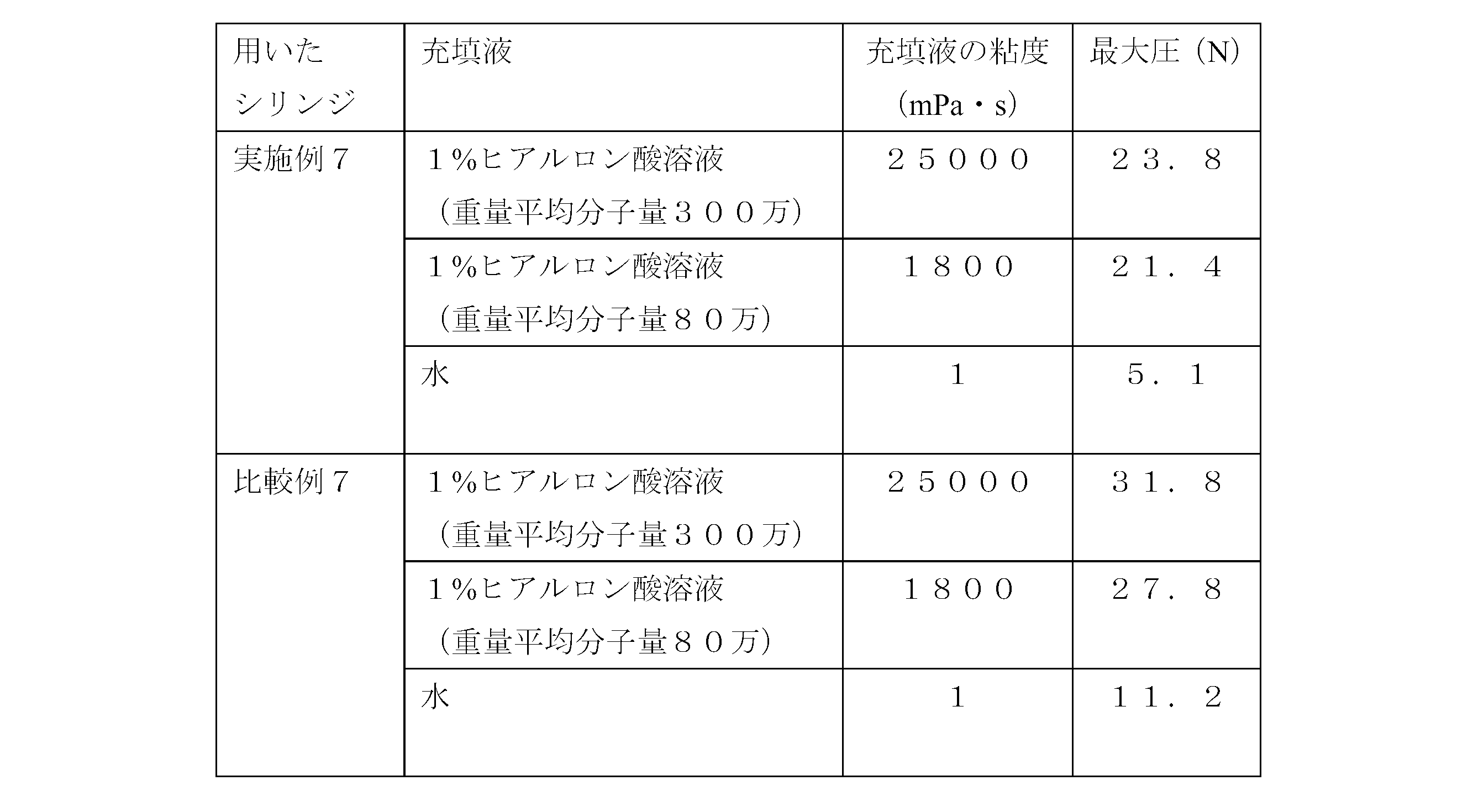
- Example 7 Comparative Example 7 in Table 3, it can be seen that the initial dynamic pressure (adhesion) was greatly improved by managing the gasket tolerance.
- Table 4 also shows that the maximum pressure was improved by managing the gasket tolerances.
- Examples 8 to 13 and Comparative Examples 8 to 12 Silicone oil (Shin-Etsu Chemical Co., Ltd.) having a kinematic viscosity of 5,000 cSt on the inner peripheral surface of a barrel having a capacity of 5 ml, a cylinder outer diameter of 15.05 mm, a cylinder inner diameter of 12.45 mm, and a total length of 79.0 mm, which is mainly composed of COP resin.
- “KF-96-5000cs” manufactured by the company was sprayed under the following conditions so as to be in the range of 0 to 150 ⁇ g per cm 2 .
- ⁇ Sliding resistance evaluation> For each prefilled syringe, the sliding resistance between the barrel and the gasket was evaluated according to the following criteria. ⁇ (Best): The maximum value of the pressure applied when the gasket starts to move is not recognized, and the extrusion pressure after the gasket starts moving does not vary. ⁇ (Good): The pressure applied when the gasket starts to move is within the allowable range, and there is no variation in the extrusion pressure after the gasket starts moving. X (defect): The pressure applied when the gasket starts to move is within an allowable range, but the extrusion pressure after the gasket starts moving varies.
Abstract
Description
プレフィルドシリンジのバレルは、中心軸に垂直な方向に対しては、中心軸を曲率中心として透過光が大きく屈折してしまう。従って、中心軸と垂直な方向に生じる屈折は、専らバレルの形状による影響が大きく、バレルの内周面におけるシリコーンオイルの僅かな塗布状態の差異を反映することはできない。一方、バレルは中心軸方向に対しては実質的に屈曲していないため、中心軸と同一方向に生じる光軸からの分岐、すなわち本発明における「屈折角」はバレルの形状による影響を受けにくく、シリコーンオイルの塗布状態を直接的に反映することができる。 The “refraction angle” in the present invention means that when a prefilled syringe filled with a drug is irradiated with incident light having an optical axis perpendicular to the central axis of the barrel, the optical axis of transmitted light diffused in the same direction as the central axis is used. Represents the opening angle of.
In the barrel of the prefilled syringe, the transmitted light is largely refracted with the central axis as the center of curvature in the direction perpendicular to the central axis. Therefore, the refraction generated in the direction perpendicular to the central axis is largely influenced by the shape of the barrel, and cannot reflect a slight difference in the application state of the silicone oil on the inner peripheral surface of the barrel. On the other hand, since the barrel is not substantially bent with respect to the central axis direction, the branch from the optical axis that occurs in the same direction as the central axis, that is, the “refraction angle” in the present invention is not easily affected by the shape of the barrel. The application state of silicone oil can be directly reflected.
10 シリンジ
20 バレル
21 先端開口部
22 フランジ
23 螺合部
24 ガスケット
25 プランジャー
26 キャップ部材
27 薬剤
28 シリコーン膜
31 レーザー発振装置
32 投影板
33 入射光
34 透過光
40 中心軸
41 光軸
42 投影像 DESCRIPTION OF SYMBOLS 1
バレル20は、図1に示すように、筒状体であり、先端には、注射針を取付けるための先端開口部21が設けられており、後端には、薬剤注入操作時に指をかけるための一対のフランジ22が対向して設けられている。 <Barrel>
As shown in FIG. 1, the
光線透過率:92%
屈折率:1.53 Among them, a cyclic olefin polymer (COP) or a cyclic olefin copolymer (COC) having particularly excellent permeability is preferable from the viewpoint of improving the efficiency and accuracy of visual inspection of contents. Such a resin is a thermoplastic saturated norbornene-based resin composition marketed under the Zeonex (registered trademark) by Nippon Zeon Co., Ltd., and is incompatible with the thermoplastic saturated norbornene-based resin. What disperse | distributed compounding agents, such as a certain rubbery polymer, is preferable. In particular, those having the following characteristics are most preferable.
Light transmittance: 92%
Refractive index: 1.53
ガスケット24は、特に材料を限定しないが、気密性を維持するために、ゴム、熱可塑性エラストマー等の弾性体により形成されることが好ましい。なかでも、オートクレーブ滅菌における寸法変化の少ないブチルゴムを主原料とすることが特に好ましい。ブチルゴムとしては、架橋性、接着性などを改善するために塩素化や臭素化を施した、ハロゲン化ブチルゴムを使用することもできる。もっとも、医療用器具として使用が許容され、従来からシリンジのガスケットの形成材料として使用されているものであれば、特に限定されない。また、ガスケットの表面材料としては、特に限定するものではないが、例えばコスト低減の観点からはテトラフルオロエチレン樹脂フィルムや超高分子量ポリエチレンフィルムによる表面加工をしていないものが好ましい。なお、ガスケットが固着する可能性をより低減するため、ガスケット表面にシリコーンオイルを塗布することもできる。 <Gasket>
The
本実施形態のシリンジ10では、ガスケット24の最大外径が、バレル20の内径よりも大きいことが必要である。このようにガスケット24の最大外径が、バレル20の内径よりも大きいことによって、ガスケット24およびバレル20の隙間から薬剤27が漏れ出ることを抑制することができ、ガスケット24の密封性を維持することができる。 <Dimensional difference between barrel and gasket>
In the
また、プランジャー25は、ガスケット24をバレル20内で摺動させるに必要な押し込み力および曲げに耐え得る強度を備えていれば十分であり、例えばポリエチレンやポリプロピレン等の硬質プラスチック材料からなるものが挙げられるが、医療用器具として使用が許容され、従来からプランジャーの形成材料として使用されているものであれば、特に限定されない。 <Plunger>
Further, the
キャップ部材26は、バレル20の先端開口部21に密着し、先端開口部21を気密にシールするものであり、ブチルゴム、高密度ポリエチレン、ポリプロピレン、ポリスチレン、ポリエチレンテレフタレート等の弾性体または硬質樹脂からなるものを使用できるが、医療用器具として使用が許容され、従来からキャップ部材の形成材料として使用されているものであれば、特に限定されない。本実施形態では、キャップ部材26の内周面に、バレル20の先端開口部21の外周面に形成された螺合部23と螺合する雌ねじ部が形成されている。 <Cap member>
The
バレル20の内周面には、後述する所定の動粘度のシリコーンオイルを噴霧することによって形成されたシリコーン膜28が設けられている。バレル20に塗布されるシリコーンオイルは単位面積あたり所定の塗布量を満たしていれば足りるため、シリコーン膜28の厚みはバレル20の全域において必ずしも均一である必要はない。 <Silicone membrane>
A
バレル内周面に塗布されシリコーン膜28を形成するシリコーンオイルは、基本的にはポリジメチルシロキサンであるが、潤滑性を損なわない範囲で側鎖や末端が置換されたポリジメチルシロキサンを用いることができる。具体的には、ポリメチルフェニルシロキサンやポリメチルハイドロジェンシロキサンなどがあげられる。シリコーンオイルには、必要に応じて各種添加剤を配合してもよい。 (Silicone oil)
The silicone oil applied to the inner peripheral surface of the barrel to form the
シリコーン膜28を構成するシリコーンオイルの塗布量は、バレル20の内周面1cm2あたり5~50μg、特に10~30μgであることが好ましい。
シリコーンオイルの塗布量がバレル内周面1cm2あたり5μg以上であれば、バレル20とガスケット24との間に十分な摺動性を確保することができる。また、この塗布量がバレル内周面1cm2あたり50μg以下であれば、薬剤27を充填する場合に、仮に薬剤へのシリコーンオイルの巻き込みが生じたとしても、巻き込み量を極めて微量に抑えることができる。さらに、肉眼で観察する限りバレル20の内周面にギラツキを感じることもない。 (Thickness of silicone film)
The application amount of the silicone oil constituting the
If the amount of silicone oil applied is 5 μg or more per 1 cm 2 of the inner peripheral surface of the barrel, sufficient slidability can be ensured between the
シリコーン膜28は、前記動粘度を有するシリコーンオイルを、高粘度液剤に対応したスプレーシステムを用いて、バレル20の内周面に均一に噴霧することにより形成される。本発明では、塗布するシリコーンオイルが高動粘度であるため、シリコーンオイルをバレル20内周面に均一に塗布できるよう、適宜、液温度、エア圧力、ノズル径、塗布時間等を調節する必要がある。
特に、上記高動粘度のシリコーンオイルの場合、噴霧の際に、特にシリコーンオイルを加熱することにより、シリコーンオイルの噴霧が容易となる。 (Method of forming silicone film)
The
In particular, in the case of the above-mentioned high kinematic viscosity silicone oil, the silicone oil can be easily sprayed by heating the silicone oil especially during spraying.
ガスケットにシリコーンオイルを塗布する場合、バレル内周面に塗布するシリコーンオイルと同様、25℃における動粘度が500~100,000cStであるものが好ましく、特に1,000~50,000cStのものがより好ましく用いられる。動粘度が500cSt以上であれば、塗布したシリコーンオイルが流れることがなく、潤滑作用が長期間持続する。また、動粘度が100,000cSt以下であれば、ガスケット表面全体に均一に塗布することができる。塗布方法としては、従来から使用されている方法を用いることができるが、例えば、ガスケットを入れた槽内に直接シリコーンオイルを投入して撹拌する方法、シリコーンオイルを懸濁させた水中でガスケットを撹拌する方法などを用いることができる。 (Silicone oil applied to the gasket surface)
When silicone oil is applied to the gasket, it is preferable that the kinematic viscosity at 25 ° C. is 500 to 100,000 cSt, particularly 1,000 to 50,000 cSt, similar to the silicone oil applied to the inner peripheral surface of the barrel. Preferably used. When the kinematic viscosity is 500 cSt or more, the applied silicone oil does not flow, and the lubricating action lasts for a long time. Moreover, if kinematic viscosity is 100,000 cSt or less, it can apply | coat uniformly on the whole gasket surface. As a coating method, a conventionally used method can be used. For example, a method in which silicone oil is directly put into a tank in which a gasket is placed and stirred, and a gasket is placed in water in which silicone oil is suspended. A method of stirring can be used.
ガスケットにシリコーンオイルを塗布する場合でも、薬剤へのシリコーンオイルの巻き込みを抑えるために塗布量は必要最小限とすべきであることから、シリコーンオイルの塗布量はガスケット表面の面積1cm2あたり0.3mg以下とするのが好ましく、0.15mg以下とするのがより好ましい。 (The amount of silicone oil applied to the gasket surface per unit area)
Even when applying silicone oil to the gasket, the coating amount in order to suppress entrainment of the silicone oil to the drug because it should be the minimum necessary, the area 1 cm 2 per 0 coating amount of the silicone oil gasket surface. The amount is preferably 3 mg or less, and more preferably 0.15 mg or less.
薬剤27は、プレフィルドタイプのシリンジに充填できるものであれば特に限定されないが、上記構成のシリンジ10は、高粘度の薬剤を充填するのに特に適している。通常、高粘度の薬剤を充填すると、バレル内周面に高いズリ応力がかかるため、バレル内周面に塗布されたシリコーンオイルを薬剤中に巻き込みやすく、その結果、濁りを生じやすい。しかし、上記所定の粘度のシリコーンオイルをバレルの内周面に単位面積当たり上記所定の塗布量で塗布すると、シリコーンオイルの巻き込み量を微量にとどめることができる。そのため、上記構成のシリンジ10は、充填時に濁りを生じやすい高粘度の薬剤に特に適していると言える。 <Drug>
The
従って、例えば、上記構成のシリンジ10は、粘度が60,000mPa・s程度の高粘度薬剤であっても安定に収容することができ、このような薬剤としては、特に、重量平均分子量が60~370万の高分子量ヒアルロン酸ナトリウムの1%水溶液を挙げることができる。 In addition, when the high-
Therefore, for example, the
図2は、屈折角を測定するための装置の一態様を示す概念図である。
この屈折角測定装置は、プレフィルドシリンジ1に光線(入射光33)を照射するレーザー発振装置31およびプレフィルドシリンジ1を出た光線(透過光34)を投影する投影板32とを用いる。 <Refraction angle measuring device>
FIG. 2 is a conceptual diagram showing an aspect of an apparatus for measuring a refraction angle.
This refraction angle measuring device uses a laser oscillation device 31 that irradiates the prefilled syringe 1 with a light beam (incident light 33) and a
投影板32は、表面に歪みがなく不透明な平板であれば特に制限されない。投影板32は、レーザー発振装置31から照射される光線の光軸41に対して垂直となるように配置される。 The laser oscillation device 31 is a device for irradiating the prefilled syringe 1 filled with a medicine with incident light 33 having an
The
上記装置を用いて屈折角を測定するには、まずレーザー発振装置31の位置を固定し、次いで、レーザー発振装置31から照射される光線の光軸41と垂直になるように投影板32を固定する。この状態、すなわち測定対象であるプレフィルドシリンジ1を配置していない状態で、レーザー発振装置31から照射される光線を投影板32に投影する。投影像42の形状が、略円形となるレーザー発振装置を使用する場合、投影像42の直径を入射光33の光幅「A」とする。投影像42の形状が略楕円形となるものを使用する場合は、楕円の短軸方向がバレルの中心軸方向と一致するようレーザー発振装置の向きを調整する。この場合、楕円の短軸の長さを入射光33の光幅「A」とする。なお、投影像42が円、楕円以外の形状となるレーザー発振装置は本発明における屈折角測定には適しない。入射光33の光幅「A」は、太くなると屈折角の差が見えにくくなることから、3.0mm以下であることが好ましく、2.0mm以下であることがより好ましい。 <Measurement method of refraction angle>
In order to measure the refraction angle using the above apparatus, the position of the laser oscillation device 31 is first fixed, and then the
プレフィルドシリンジ1を上記の通り配置した状態で、レーザー発振装置31から光線(入射光33)をプレフィルドシリンジ1に照射し、プレフィルドシリンジ1から出る透過光34を投影板32に投影する。投影板32に投影された投影像42の中心軸40と同一方向の幅「D」、並びに、プレフィルドシリンジ1の中心軸40から投影板32までの距離「L」を測定する。 Next, the prefilled syringe 1 that is a measurement target is disposed at a predetermined position on the
With the prefilled syringe 1 disposed as described above, the prefilled syringe 1 is irradiated with light rays (incident light 33) from the laser oscillation device 31, and the transmitted light 34 emitted from the prefilled syringe 1 is projected onto the
屈折角θ=tan-1((D-A)/2L) The refraction angle is the optical axis of the transmitted light 34 diffused in the same direction as the
Refraction angle θ = tan-1 ((DA) / 2L)
例えば、上記実施の形態では、バレル20全体を単一の区画として薬剤を充填する形態としたが、バレル20内を一以上の密封栓で仕切って複数の区画に分割した多区画のシリンジ形態としてもよい。この場合には、薬剤の汚染や漏れをより確実に防止したり、一本のシリンジに複数の薬剤を充填したりすることが可能である。 As mentioned above, although embodiment of this invention was described with reference to drawings, these are the illustrations of this invention, Various structures other than the above are also employable.
For example, in the above-described embodiment, the
COP樹脂を主成分として形成された容量5ml、筒外径15.05mm、筒内径12.45mm、全長79.0mmのバレルの内周面に、動粘度が5,000cStのシリコーンオイル(信越化学工業社製「KF-96-5000cs」)を、1cm2あたり12~25μgの範囲で平均塗布量が18μgとなるように以下の条件で噴霧した。COP樹脂は、日本ゼオン株式会社からZeonex(登録商標)として市販されている熱可塑性飽和ノルボルネン系樹脂組成物を用いた。
(シリコーンオイル噴霧条件)
噴霧時間:0.05秒
エア圧力:0.5MPa
シリコーンオイル加熱温度:180℃
ノズル径:1.0mm <Example 1>
Silicone oil (Shin-Etsu Chemical Co., Ltd.) with a kinematic viscosity of 5,000 cSt on the inner peripheral surface of a barrel with a capacity of 5 ml, a cylinder outer diameter of 15.05 mm, a cylinder inner diameter of 12.45 mm, and a total length of 79.0 mm, which is formed mainly of COP resin. “KF-96-5000cs” manufactured by the company was sprayed under the following conditions so that the average coating amount was 18 μg in the range of 12 to 25 μg per cm 2 . As the COP resin, a thermoplastic saturated norbornene resin composition commercially available as Zeonex (registered trademark) from Nippon Zeon Co., Ltd. was used.
(Silicone oil spraying conditions)
Spraying time: 0.05 seconds Air pressure: 0.5 MPa
Silicone oil heating temperature: 180 ° C
Nozzle diameter: 1.0mm
シリコーンオイルを噴霧しないこと以外は実施例1と同様のバレル(比較例1)を準備し、上記実施例1のバレルと光線透過率を比較した。光線透過率の測定には、以下の装置および方法を用いた。
(装置)
・分光光度計(株式会社日立ハイテクノロジーズ社製、型番:U-3310)
・波長:660nm
(方法)
・分光光度計の試料室に何も入れない状態で分光光度計の0点合わせをする。
・分光光度計の試料室にバレルを固定する。このとき、光源からバレルまでの距離は常に一定とし、光線がバレルの中心軸上であってバレル先端から20mmの位置に当たるよう調整する。
・対照のセルホルダには何も入れない状態で、吸光度の値を読みとる。
測定結果を以下の表1に示す。 <Change in light transmittance due to formation of silicone film>
A barrel similar to Example 1 (Comparative Example 1) was prepared except that the silicone oil was not sprayed, and the light transmittance was compared with the barrel of Example 1 above. The following apparatus and method were used for the measurement of light transmittance.
(apparatus)
・ Spectrophotometer (manufactured by Hitachi High-Technologies Corporation, model number: U-3310)
・ Wavelength: 660nm
(Method)
・ Set the spectrophotometer to zero with nothing in the spectrophotometer sample chamber.
• Secure the barrel in the spectrophotometer sample chamber. At this time, the distance from the light source to the barrel is always constant, and the light beam is adjusted so as to be on the central axis of the barrel and 20 mm from the barrel tip.
• Read the absorbance value with nothing in the control cell holder.
The measurement results are shown in Table 1 below.
実施例1と同様の方法でシリコーン膜を形成したバレルを作製し、このバレルにキャップ部材を取り付けた上で、重量平均分子量が300万の高分子量ヒアルロン酸ナトリウムの1%水溶液(粘度=25,000mPa・s)を2.9ml充填し、ガスケットを打栓してプレフィルドシリンジを組み上げた。 <Example 2>
A barrel in which a silicone film was formed by the same method as in Example 1 was prepared, and a cap member was attached to the barrel. Then, a 1% aqueous solution of high molecular weight sodium hyaluronate having a weight average molecular weight of 3 million (viscosity = 25, 000 mPa · s) was filled, and the gasket was plugged to assemble a prefilled syringe.
シリコーンオイルとして、動粘度が1,000cStのシリコーンオイル(信越化学工業社製「KF-96-1000cs」)を用いたこと以外は、実施例1と同様にシリコーン膜を形成したバレルを作製し、このバレルを用いて実施例2と同様にプレフィルドシリンジを組み上げた。 <Example 3>
A barrel having a silicone film formed in the same manner as in Example 1 except that a silicone oil having a kinematic viscosity of 1,000 cSt (“KF-96-1000cs” manufactured by Shin-Etsu Chemical Co., Ltd.) was used as the silicone oil. Using this barrel, a prefilled syringe was assembled in the same manner as in Example 2.
シリコーンオイルとして、動粘度が30,000cStのシリコーンオイル(信越化学工業社製「KF-96H-3万cs」)を用いたこと以外は、実施例1と同様にシリコーン膜を形成したバレルを作製し、このバレルを用いて実施例2と同様にプレフィルドシリンジを組み上げた。 <Example 4>
A barrel formed with a silicone film was prepared in the same manner as in Example 1 except that a silicone oil having a kinematic viscosity of 30,000 cSt (“KF-96H-30,000 cs” manufactured by Shin-Etsu Chemical Co., Ltd.) was used as the silicone oil. Then, using this barrel, a prefilled syringe was assembled in the same manner as in Example 2.
さらにガスケットの表面にシリコーンオイルを表面1cm2あたり0.1mg塗布することにした。すなわち、水の入ったタンクに、動粘度が5,000cStのシリコーンオイルを、全ガスケットの表面積の合計に対して1cm2あたり0.13mgとなる量を投下し、10分間撹拌して分散させた。この中にガスケットを投入し、下から蒸気を吹き込みながら100℃で10分間撹拌後、排水、すすぎを行い、オートクレーブにて滅菌を行った。シリコーンオイル塗布量を重量測定により確認すると、ガスケット表面1cm2あたり0.10mgとなっていることが確認された。このガスケットを用いたこと以外は実施例2と同様にプレフィルドシリンジを組み上げた。 <Example 5>
Furthermore, it was decided to apply 0.1 mg of silicone oil to 1 cm 2 of the surface of the gasket. That is, a silicone oil having a kinematic viscosity of 5,000 cSt was dropped into a tank containing water in an amount of 0.13 mg per 1 cm 2 with respect to the total surface area of all gaskets, and stirred for 10 minutes to disperse. . The gasket was put into this, and it stirred for 10 minutes at 100 degreeC, blowing steam from the bottom, drained and rinsed, and sterilized by the autoclave. When the amount of silicone oil applied was confirmed by weight measurement, it was confirmed that the amount was 0.10 mg per 1 cm 2 of the gasket surface. A prefilled syringe was assembled in the same manner as in Example 2 except that this gasket was used.
さらにガスケットの表面にシリコーンオイルを表面1cm2あたり0.2mg塗布することにした。塗布方法は実施例5と同様だが、全ガスケットの表面積の合計に対して1cm2あたり0.26mgとなる量のシリコーンオイルを投下した。シリコーンオイル塗布量を実施例5と同様に確認したところ、ガスケット表面1cm2あたり0.20mgであった。このガスケットを用いたこと以外は実施例2と同様にプレフィルドシリンジを組み上げた。 <Example 6>
Furthermore, it was decided to apply 0.2 mg of silicone oil to 1 cm 2 of the surface of the gasket. The application method was the same as in Example 5, but an amount of silicone oil of 0.26 mg per cm 2 was dropped with respect to the total surface area of all gaskets. When the amount of silicone oil applied was confirmed in the same manner as in Example 5, it was 0.20 mg per 1 cm 2 of the gasket surface. A prefilled syringe was assembled in the same manner as in Example 2 except that this gasket was used.
シリコーンオイルとして、動粘度が350cStのシリコーンオイル(信越化学工業社製「KF-96-350cs」)を用いたこと以外は、実施例1と同様にシリコーン膜を形成したバレルを作製し、このバレルを用いて実施例2と同様にプレフィルドシリンジを組み上げた。 <Comparative example 2>
A barrel formed with a silicone film was prepared in the same manner as in Example 1 except that a silicone oil having a kinematic viscosity of 350 cSt (“KF-96-350cs” manufactured by Shin-Etsu Chemical Co., Ltd.) was used as the silicone oil. A prefilled syringe was assembled in the same manner as in Example 2.
シリコーンオイルとして、動粘度が300,000cStのシリコーンオイル(信越化学工業社製「KF-96-30万cs」)370gと、動粘度が100,000cStのシリコーンオイル(信越化学工業社製「KF-96-10万cs」)630gとを混合して調製した動粘度が150,000cStの混合シリコーンオイルを用いたこと以外は、実施例1と同様にシリコーン膜を形成したバレルを作製し、このバレルを用いて実施例2と同様にプレフィルドシリンジを組み上げた。 <Comparative Example 3>
As the silicone oil, 370 g of silicone oil having a kinematic viscosity of 300,000 cSt (“KF-96-300,000 cs” manufactured by Shin-Etsu Chemical Co., Ltd.) and silicone oil having a kinematic viscosity of 100,000 cSt (“KF- manufactured by Shin-Etsu Chemical Co., Ltd.) A barrel formed with a silicone film was prepared in the same manner as in Example 1 except that a mixed silicone oil having a kinematic viscosity of 150,000 cSt prepared by mixing 630 g with 960 g was used. A prefilled syringe was assembled in the same manner as in Example 2.
シリコーン膜の1cm2あたりの平均塗布量が100μgとなるようにシリコーンオイルを噴霧したこと以外は、実施例1と同様にシリコーン膜を形成したバレルを作製し、このバレルを用いて実施例2と同様にプレフィルドシリンジを組み上げた。 <Comparative example 4>
A barrel formed with a silicone film was prepared in the same manner as in Example 1 except that the silicone oil was sprayed so that the average coating amount per cm 2 of the silicone film was 100 μg. Using this barrel, Example 2 and Similarly, a prefilled syringe was assembled.
さらにガスケットの表面にシリコーンオイルを表面1cm2あたり0.4mg塗布することにした。塗布方法は実施例5と同様だが、全ガスケットの表面積の合計に対して1cm2あたり0.52mgとなる量のシリコーンオイルを投下した。シリコーンオイル塗布量を実施例5と同様に確認したところ、ガスケット表面1cm2あたり0.41mgであった。このガスケットを用いたこと以外は実施例2と同様にプレフィルドシリンジを組み上げた。 <Comparative Example 5>
Furthermore, it was decided to apply 0.4 mg of silicone oil to 1 cm 2 of the surface of the gasket. The application method was the same as in Example 5, but an amount of silicone oil of 0.52 mg per cm 2 was dropped with respect to the total surface area of all gaskets. When the amount of silicone oil applied was confirmed in the same manner as in Example 5, it was 0.41 mg per 1 cm 2 of the gasket surface. A prefilled syringe was assembled in the same manner as in Example 2 except that this gasket was used.
薬剤中における濁りの有無およびバレル内周面のギラツキの有無を、熟練した品質検査担当者からなるパネリスト5名を集めて目視により評価した。その結果を表2に示す。
濁り評価基準:
○(良) : 濁りは全く確認されない。
×(不良): 濁りが確認される。
ギラツキ評価基準:
○(良) : ギラツキは全く観察されない。
×(不良): ギラツキが観察される。 <Visual evaluation>
The presence or absence of turbidity in the drug and the presence or absence of glare on the inner peripheral surface of the barrel were evaluated visually by collecting five panelists composed of skilled quality inspection personnel. The results are shown in Table 2.
Turbidity evaluation criteria:
○ (Good): No turbidity is confirmed.
X (defect): Turbidity is confirmed.
Glare evaluation criteria:
○ (Good): No glare is observed.
X (defect): Glare is observed.
プレフィルドシリンジの先端に注射針(23G×1 1/4 テルモ社製)を装着し、試験機(島津製作所社製「EZ-TEST」)を用いて、100mm/minの押し出し速度で薬剤を吐出させたときの初動圧と押し出し圧を測定した。なお、初動圧測定は、作製より1カ月間、40℃で保存した試料を使用した。その結果を表2に示す。
初動圧評価基準:
◎(最良): 押し始めから5mm未満のデータについて、ガスケットが動き始める時にかかる圧の極大値が認められない。
○(良): 押し始めから5mm未満のデータについて、ガスケットが動き始める時にかかる圧の極大値が30N以下。
×(不良): 押し始めから5mm未満のデータについて、ガスケットが動き始める時にかかる圧の極大値が30N超。
押し出し圧評価基準:
○(良): 押し始めから5mm以降のデータについて、押し出し圧のバラツキが5N以内で、かつ押し出し圧の最大値が30N以下。
×(不良): 押し始めから5mm以降のデータについて、押し出し圧のバラツキが5N超または、押し出し圧の最大値が30N超。 <Sliding resistance evaluation>
Attach an injection needle (23G × 1 1/4 Terumo) to the tip of the prefilled syringe, and use a tester (“EZ-TEST” manufactured by Shimadzu Corporation) to discharge the drug at an extrusion speed of 100 mm / min. The initial dynamic pressure and the extrusion pressure were measured. In addition, the initial dynamic pressure measurement used the sample preserve | saved at 40 degreeC for one month from preparation. The results are shown in Table 2.
Initial dynamic pressure evaluation criteria:
A (best): For data less than 5 mm from the beginning of pushing, the maximum value of the pressure applied when the gasket starts to move is not recognized.
○ (Good): For data less than 5 mm from the start of pushing, the maximum value of the pressure applied when the gasket starts to move is 30 N or less.
X (Bad): For data less than 5 mm from the start of pushing, the maximum value of the pressure applied when the gasket starts to move is over 30N.
Extrusion pressure evaluation criteria:
○ (Good): For data after 5 mm from the start of pushing, the variation in the extrusion pressure is within 5N, and the maximum value of the extrusion pressure is 30N or less.
X (defect): For data after 5 mm from the beginning of pushing, the variation in the extrusion pressure is more than 5N or the maximum value of the extrusion pressure is more than 30N.
COP樹脂を主成分として形成された容量5ml、外径15.05±0.1mm、内径12.45±0.05mm、全長79.0±0.2mm、フランジ径φ22.0±0.2mmの公差管理を行って製造・検査されたバレルの内周面に、動粘度が5,000cStのシリコーンオイル(信越化学工業社製「KF-96」)を以下の条件で噴霧し、1cm2あたりの平均塗布量が18μgであるシリコーン膜を形成した。COP樹脂は、日本ゼオン株式会社からZeonex(登録商標)として市販されている熱可塑性飽和ノルボルネン系樹脂組成物を用いた。なお、このバレルの製造・検査の際には、特に内径の公差管理(±0.05mm)を厳密に行った。
(シリコーンオイル噴霧条件)
噴霧時間:0.05秒
エア圧力:0.5MPa
シリコーンオイル加熱温度:180℃
ノズル径:1.0mm <Example 7>
COP resin as a main component with a capacity of 5 ml, outer diameter 15.05 ± 0.1 mm, inner diameter 12.45 ± 0.05 mm, overall length 79.0 ± 0.2 mm, flange diameter φ22.0 ± 0.2 mm the inner circumferential surface of the tolerance was controlled manufacturing and inspection performed barrel, kinematic viscosity was sprayed under the following conditions 5,000cSt silicone oil (Shin-Etsu Chemical Co., Ltd. "KF-96"), per 1 cm 2 A silicone film having an average coating amount of 18 μg was formed. As the COP resin, a thermoplastic saturated norbornene resin composition commercially available as Zeonex (registered trademark) from Nippon Zeon Co., Ltd. was used. When manufacturing and inspecting the barrel, tolerance control (± 0.05 mm) of the inner diameter was performed strictly.
(Silicone oil spraying conditions)
Spraying time: 0.05 seconds Air pressure: 0.5 MPa
Silicone oil heating temperature: 180 ° C
Nozzle diameter: 1.0mm
実施例7と基本的には同じシリンジであるが、ガスケットとして、ブチルゴムの表面にテトラフルオロエチレン樹脂フィルムを積層させ、公差が外径φ12.70±0.10mm(第一の山部)、φ12.0±0.10mm(谷部)、全長10.0±0.30mmのものを用い、シリコーンオイルを塗布していない点が異なるシリンジを用意した。 <Comparative Example 6>
The syringe is basically the same as Example 7, but as a gasket, a tetrafluoroethylene resin film is laminated on the surface of butyl rubber, and the tolerance is outer diameter φ12.70 ± 0.10 mm (first peak), φ12 0.0 ± 0.10 mm (valley) and a total length of 10.0 ± 0.30 mm were used, and syringes different in that silicone oil was not applied were prepared.
実施例7と基本的には同じシリンジであるが、COP樹脂を主成分として形成された容量5ml、外径15.05±0.1mm、内径12.45±0.20mm、全長79.0±0.2mm、フランジ径φ22.0±0.2mmの公差管理を行って製造・検査されたバレルを用いた点が異なるシリンジを用意した。 <Comparative Example 7>
Basically the same syringe as in Example 7, but with a volume of 5 ml formed with COP resin as the main component, outer diameter 15.05 ± 0.1 mm, inner diameter 12.45 ± 0.20 mm, total length 79.0 ± Different syringes were prepared using barrels manufactured and inspected with tolerance management of 0.2 mm and flange diameter φ22.0 ± 0.2 mm.
ここで、この実施例7では、組み合わせ公差としては、最も緩い場合で、バレル内径φ12.50mm、ガスケットの第一の山部φ12.60mmであるため、その差は0.10mmとなる。この場合にも、下記のとおり実液漏れ試験を行い、気密性が確保できることを確認した。一方、この実施例7では、組み合わせ公差としては、最もきつい場合で、バレル内径φ12.40mm、ガスケットの第一の山部φ12.80mmであるため、その差は0.40mmとなる。この場合にも、摺動性が良好であることを確認した(データ不図示)。 <Slidability and airtightness test>
Here, in this Example 7, as the combination tolerance, in the loosest case, the inner diameter of the barrel is 12.50 mm and the first peak portion of the gasket is 12.60 mm, so the difference is 0.10 mm. Also in this case, the actual liquid leakage test was performed as follows, and it was confirmed that airtightness could be secured. On the other hand, in the seventh embodiment, the combination tolerance is the tightest case, the barrel inner diameter φ12.40 mm and the first peak portion φ12.80 mm of the gasket, so the difference is 0.40 mm. Also in this case, it was confirmed that the slidability was good (data not shown).
一定の圧力がかかった場合でも、薬液がガスケットの隙間から漏れないことを確認するために、以下の手順で実液漏れ試験を行った。
1)先端を熔封した注射針をシリンジに装着する。
2)押し出し試験機(島津製作所社製EZ-TEST)でプランジャーロッドを押し、押し出し圧が19~24Nの範囲内となるよう押し子の位置を調整し、30秒間保持する。
3)シリンジを取り出し、ガスケットの隙間から薬液が漏れていないかを目視で確認する。
その結果、実施例7の場合には、n数=50として実液漏れ試験を行ったが、薬液漏れが起こったサンプルは存在せず、気密性が確保できることを確認した。 <Real liquid leak test>
In order to confirm that the chemical liquid does not leak from the gap between the gaskets even when a certain pressure is applied, an actual liquid leakage test was performed according to the following procedure.
1) A syringe needle with a sealed tip is attached to the syringe.
2) Press the plunger rod with an extrusion tester (EZ-TEST, manufactured by Shimadzu Corporation), adjust the position of the pusher so that the extrusion pressure is within the range of 19 to 24N, and hold it for 30 seconds.
3) Take out the syringe and visually check for chemical leakage from the gasket gap.
As a result, in the case of Example 7, the actual liquid leakage test was performed with n number = 50, but it was confirmed that there was no sample in which the chemical liquid leakage occurred and the airtightness could be secured.
以下の摺動抵抗測定では、シリンジ先端に注射針(23G×1 1/4 テルモ社製)とプランジャーを装着し、プランジャーを100mm/minの速度で押し出した時の押し出し圧を、押し出し試験機(島津製作所社製EZ-TEST)を用いて測定した。表3には、各10本のシリンジについて、薬液を充填しない状態で、初動圧(押し始めから5mm以内に現れるピークにおける押し出し圧)を測定した結果を示す。表4には、各10本のシリンジについて、薬液を充填して、最大圧(押し出し圧の最大値)を測定した結果を示す。 <Test of initial dynamic pressure and maximum pressure>
In the following sliding resistance measurement, an injection needle (23G × 1 1/4 Terumo) and a plunger are attached to the tip of the syringe, and the extrusion pressure when the plunger is extruded at a speed of 100 mm / min is used as an extrusion test. This was measured using a machine (EZ-TEST manufactured by Shimadzu Corporation). Table 3 shows the results of measuring the initial dynamic pressure (extrusion pressure at a peak appearing within 5 mm from the start of pressing) for each of the ten syringes without filling the chemical solution. Table 4 shows the results of measuring the maximum pressure (maximum value of the extrusion pressure) for each of the ten syringes filled with a chemical solution.


実施例7および比較例7のシリンジに異なる粘度の液を充填して40℃1ヶ月保管後、摺動性を測定、比較した(ガスケットは同じ)。試験結果を表5に示す。 <Slidability comparison test of samples with different viscosities>
The syringes of Example 7 and Comparative Example 7 were filled with liquids having different viscosities and stored at 40 ° C. for 1 month, and the slidability was measured and compared (the same gasket). The test results are shown in Table 5.
COP樹脂を主成分として形成された容量5ml、筒外径15.05mm、筒内径12.45mm、全長79.0mmのバレルの内周面に、動粘度が5,000cStのシリコーンオイル(信越化学工業社製「KF-96-5000cs」)を、1cm2あたり0~150μgの範囲となるように以下の条件で噴霧した。COP樹脂は、日本ゼオン株式会社からZeonex(登録商標)として市販されている熱可塑性飽和ノルボルネン系樹脂組成物を用いた。
(シリコーンオイル噴霧条件)
噴霧時間:0.05秒
エア圧力:0.5MPa
シリコーンオイル加熱温度:180℃
ノズル径:1.0mm
このバレルにキャップ部材を取り付けた上で、重量平均分子量が300万の高分子量ヒアルロン酸ナトリウムの1%水溶液(粘度=25,000mPa・s)を2.9ml充填し、上記と同一のシリコーンオイルを1cm2あたり0.10mg塗布したガスケットを打栓してプレフィルドシリンジを組み上げた。 <Examples 8 to 13 and Comparative Examples 8 to 12>
Silicone oil (Shin-Etsu Chemical Co., Ltd.) having a kinematic viscosity of 5,000 cSt on the inner peripheral surface of a barrel having a capacity of 5 ml, a cylinder outer diameter of 15.05 mm, a cylinder inner diameter of 12.45 mm, and a total length of 79.0 mm, which is mainly composed of COP resin. “KF-96-5000cs” manufactured by the company was sprayed under the following conditions so as to be in the range of 0 to 150 μg per cm 2 . As the COP resin, a thermoplastic saturated norbornene resin composition commercially available as Zeonex (registered trademark) from Nippon Zeon Co., Ltd. was used.
(Silicone oil spraying conditions)
Spraying time: 0.05 seconds Air pressure: 0.5 MPa
Silicone oil heating temperature: 180 ° C
Nozzle diameter: 1.0mm
After attaching a cap member to this barrel, 2.9 ml of a 1% aqueous solution of high molecular weight sodium hyaluronate having a weight average molecular weight of 3 million (viscosity = 25,000 mPa · s) was filled, and the same silicone oil as above was used. A gasket filled with 0.10 mg / cm 2 was stoppered to assemble a prefilled syringe.
上記のプレフィルドシリンジの屈折角の測定には、図2に示すように、以下の装置、条件および方法を用いた。
(装置)
・レーザー発振装置:RX-4N(サクラクレパス社製)
・レーザー発振装置から照射される光線の光幅(「A」):2mm
・波長:650nm
・出力:1mW未満
(条件)
・レーザー発振装置からプレフィルドシリンジの中心軸までの距離:50mm
・プレフィルドシリンジの中心軸から投影板までの距離(「L」):200mm
・照射部位:バレルの中心軸上であってバレルにおける薬剤充填領域の中央
(方法)
・一本のプレフィルドシリンジの、薬液が充填されている部分につき、中心軸を回転軸として120°ずつ回転させて3回に分けて投影板に投影された像の中心軸方向の幅(「D」)を測定し、その平均値を算出。
・得られた投影幅(「D」)、照射した光線の光幅(「A」)、およびプレフィルドシリンジの中心軸から投影板までの距離(「L」)をもとに、屈折角θを算出。 <Measurement of refraction angle>
For the measurement of the refraction angle of the prefilled syringe, the following apparatus, conditions and method were used as shown in FIG.
(apparatus)
・ Laser oscillator: RX-4N (manufactured by Sakura Crepas)
-Light width ("A") of light emitted from the laser oscillation device: 2 mm
・ Wavelength: 650 nm
・ Output: Less than 1mW (conditions)
・ Distance from laser oscillator to central axis of prefilled syringe: 50mm
・ Distance from the central axis of the prefilled syringe to the projection plate (“L”): 200 mm
・ Irradiation site: on the central axis of the barrel and the center of the drug filling area in the barrel (method)
The width of the pre-filled syringe in the direction of the central axis (“D )) And the average value is calculated.
Based on the obtained projection width (“D”), the light width of the irradiated light (“A”), and the distance from the central axis of the prefilled syringe to the projection plate (“L”), the refraction angle θ is Calculation.
各プレフィルドシリンジについて、バレル内周面のギラツキの有無を、熟練した品質検査担当者からなるパネリスト5名を集めて目視により評価した。
ギラツキ評価基準:
○(良) : ギラツキは全く観察されない。
×(不良): ギラツキが観察される。 <Evaluation of glare>
For each prefilled syringe, the presence or absence of glare on the inner peripheral surface of the barrel was evaluated visually by collecting five panelists composed of skilled quality inspection personnel.
Glare evaluation criteria:
○ (Good): No glare is observed.
X (defect): Glare is observed.
各プレフィルドシリンジについて、バレルとガスケットとの摺動抵抗を以下の基準により評価した。
◎(最良): ガスケットが動き始める時にかかる圧の極大値が認められず、ガスケットが動き出した後の押し出し圧にバラツキがない。
○(良): ガスケットが動き始める時にかかる圧が許容範囲であり、ガスケットが動き出した後の押し出し圧にバラツキがない。
×(不良): ガスケットが動き始める時にかかる圧が許容範囲であるが、ガスケットが動き出した後の押し出し圧にバラツキがある。 <Sliding resistance evaluation>
For each prefilled syringe, the sliding resistance between the barrel and the gasket was evaluated according to the following criteria.
◎ (Best): The maximum value of the pressure applied when the gasket starts to move is not recognized, and the extrusion pressure after the gasket starts moving does not vary.
○ (Good): The pressure applied when the gasket starts to move is within the allowable range, and there is no variation in the extrusion pressure after the gasket starts moving.
X (defect): The pressure applied when the gasket starts to move is within an allowable range, but the extrusion pressure after the gasket starts moving varies.
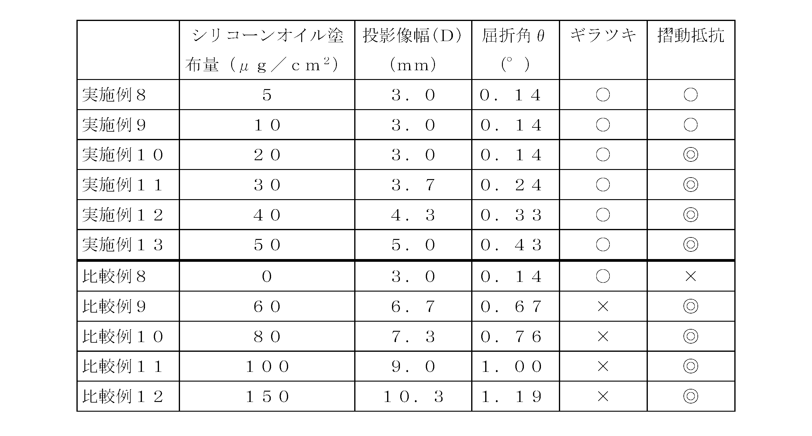
一方、屈折角が0.1~0.5°の範囲を超えると(比較例9~12)、バレルの内周面にギラツキが認められた。また、バレルの内周面にシリコーンオイルを塗布しない場合は(比較例8)、ギラツキは認められなかったものの、摺動抵抗が安定しないことが確認された。 As shown in Table 6 above, in the prefilled syringes (Examples 8 to 13) having a refraction angle in the range of 0.1 to 0.5 °, no glare is observed on the inner peripheral surface of the barrel, and the slidability It showed excellent characteristics.
On the other hand, when the refraction angle exceeded the range of 0.1 to 0.5 ° (Comparative Examples 9 to 12), glare was recognized on the inner peripheral surface of the barrel. Further, when silicone oil was not applied to the inner peripheral surface of the barrel (Comparative Example 8), although no glare was observed, it was confirmed that the sliding resistance was not stable.
Claims (13)
- 樹脂製バレルと、このバレル内に摺動自在に挿入されたガスケットと、このガスケットに取り付けられたプランジャーと、前記バレルの内周面に動粘度が500~100,000cStであるシリコーンオイルが面積1cm2あたりの塗布量が5~50μgで塗布されてなるシリコーン膜と、を有するシリンジ。 A resin barrel, a gasket slidably inserted into the barrel, a plunger attached to the gasket, and a silicone oil having a kinematic viscosity of 500 to 100,000 cSt on the inner peripheral surface of the barrel And a silicone film applied at a coating amount of 5 to 50 μg per cm 2 .
- 前記ガスケットの表面に、動粘度が500~100,000cStであるシリコーンオイルが面積1cm2あたり0~0.3mg塗布されることを特徴とする請求項1に記載のシリンジ。 2. The syringe according to claim 1, wherein a silicone oil having a kinematic viscosity of 500 to 100,000 cSt is applied to the surface of the gasket in an amount of 0 to 0.3 mg per cm 2 area.
- 前記バレルの内径の公差が±0.10mm以下になるように管理されている請求項1または2記載のシリンジ。 3. The syringe according to claim 1 or 2, wherein the syringe is managed so that a tolerance of an inner diameter of the barrel is ± 0.10 mm or less.
- 前記バレルが熱可塑性飽和ノルボルネン系樹脂組成物からなることを特徴とする請求項1ないし3のいずれか一項に記載のシリンジ。 The syringe according to any one of claims 1 to 3, wherein the barrel is made of a thermoplastic saturated norbornene resin composition.
- 前記ガスケットの最大外径が前記バレルの内径よりも大きく、
前記ガスケットの最大外径および前記バレルの内径の差が0.02mm以上0.50mm以下である請求項1ないし4のいずれか一項に記載のシリンジ。 A maximum outer diameter of the gasket is larger than an inner diameter of the barrel;
The syringe according to any one of claims 1 to 4, wherein a difference between a maximum outer diameter of the gasket and an inner diameter of the barrel is 0.02 mm or more and 0.50 mm or less. - 前記ガスケットが複数の山部を有し、
前記複数の山部のうち最も先端部に近い第一の山部の外径が、前記最大外径に相当する請求項5記載のシリンジ。 The gasket has a plurality of peaks,
The syringe according to claim 5, wherein an outer diameter of a first peak portion closest to a distal end portion among the plurality of peak portions corresponds to the maximum outer diameter. - 前記ガスケットの最大外径のオートクレーブ滅菌後の公差が±0.10mmになるように管理されている請求項1ないし6のいずれか一項に記載のシリンジ。 The syringe according to any one of claims 1 to 6, wherein the syringe is managed so that a tolerance after autoclaving of the maximum outer diameter of the gasket is ± 0.10 mm.
- 前記ガスケットがゴムまたは熱可塑性エラストマーからなる請求項1ないし7のいずれか一項に記載のシリンジ。 The syringe according to any one of claims 1 to 7, wherein the gasket is made of rubber or a thermoplastic elastomer.
- 前記ゴムがブチルゴムである請求項8に記載のシリンジ。 The syringe according to claim 8, wherein the rubber is butyl rubber.
- 薬剤を充填したバレルに波長635nm~690nm、光幅3.0mm以下の入射光をバレルの中心軸と直交する光軸で照射した際に前記中心軸と同一方向に拡散された透過光の光軸からの屈折角が0.1~0.5°の範囲である請求項1ないし9のいずれか一項に記載のシリンジ。 Optical axis of transmitted light diffused in the same direction as the central axis when incident light having a wavelength of 635 nm to 690 nm and a light width of 3.0 mm or less is irradiated to the barrel filled with the medicine with an optical axis orthogonal to the central axis of the barrel The syringe according to any one of claims 1 to 9, wherein the angle of refraction from is in the range of 0.1 to 0.5 °.
- 前記バレルの先端開口部を封止するキャップ部材と、前記バレル内に充填された薬剤とを有するプレフィルドシリンジである請求項1ないし10のいずれか一項に記載のシリンジ。 The syringe according to any one of claims 1 to 10, which is a prefilled syringe having a cap member that seals the tip opening of the barrel and a medicine filled in the barrel.
- 前記薬剤が1,000~60,000mPa・sの粘度を有することを特徴とする請求項11に記載のシリンジ。 The syringe according to claim 11, wherein the drug has a viscosity of 1,000 to 60,000 mPa · s.
- 前記薬剤がヒアルロン酸ナトリウム水溶液である、請求項11または12に記載のシリンジ。 The syringe according to claim 11 or 12, wherein the drug is a sodium hyaluronate aqueous solution.
Priority Applications (8)
| Application Number | Priority Date | Filing Date | Title |
|---|---|---|---|
| KR1020117015244A KR101704833B1 (en) | 2008-12-03 | 2009-12-03 | Syringe |
| CN200980148334.0A CN102231994B (en) | 2008-12-03 | 2009-12-03 | Syringe |
| JP2010541340A JP5517950B2 (en) | 2008-12-03 | 2009-12-03 | Syringe |
| CA2745621A CA2745621A1 (en) | 2008-12-03 | 2009-12-03 | Syringe |
| US13/132,720 US20110276005A1 (en) | 2008-12-03 | 2009-12-03 | Syringe |
| AU2009323307A AU2009323307B2 (en) | 2008-12-03 | 2009-12-03 | Syringe |
| EP09830433.0A EP2371406A4 (en) | 2008-12-03 | 2009-12-03 | Syringe |
| US15/351,686 US20170056923A1 (en) | 2008-12-03 | 2016-11-15 | Syringe |
Applications Claiming Priority (6)
| Application Number | Priority Date | Filing Date | Title |
|---|---|---|---|
| JP2008308978 | 2008-12-03 | ||
| JP2008-308978 | 2008-12-03 | ||
| JP2008-323575 | 2008-12-19 | ||
| JP2008323575 | 2008-12-19 | ||
| JP2009003518 | 2009-01-09 | ||
| JP2009-003518 | 2009-01-09 |
Related Child Applications (2)
| Application Number | Title | Priority Date | Filing Date |
|---|---|---|---|
| US13/132,720 A-371-Of-International US20110276005A1 (en) | 2008-12-03 | 2009-12-03 | Syringe |
| US15/351,686 Continuation US20170056923A1 (en) | 2008-12-03 | 2016-11-15 | Syringe |
Publications (1)
| Publication Number | Publication Date |
|---|---|
| WO2010064667A1 true WO2010064667A1 (en) | 2010-06-10 |
Family
ID=42233314
Family Applications (1)
| Application Number | Title | Priority Date | Filing Date |
|---|---|---|---|
| PCT/JP2009/070285 WO2010064667A1 (en) | 2008-12-03 | 2009-12-03 | Syringe |
Country Status (9)
| Country | Link |
|---|---|
| US (2) | US20110276005A1 (en) |
| EP (1) | EP2371406A4 (en) |
| JP (1) | JP5517950B2 (en) |
| KR (1) | KR101704833B1 (en) |
| CN (1) | CN102231994B (en) |
| AU (1) | AU2009323307B2 (en) |
| CA (1) | CA2745621A1 (en) |
| TW (1) | TWI543790B (en) |
| WO (1) | WO2010064667A1 (en) |
Cited By (10)
| Publication number | Priority date | Publication date | Assignee | Title |
|---|---|---|---|---|
| WO2012118194A1 (en) * | 2011-03-02 | 2012-09-07 | 電気化学工業株式会社 | Pre-filled syringe filling syringe having resin barrel with aqueous solution containing hyaluronic acid or salt thereof |
| JP2013034567A (en) * | 2011-08-05 | 2013-02-21 | Daikyo Seiko Ltd | Plastic-made nozzle cap |
| JP2013541380A (en) * | 2010-10-18 | 2013-11-14 | サノフィ・パスツール | Method for preserving vaccine containing aluminum adjuvant |
| JP2014028114A (en) * | 2012-07-03 | 2014-02-13 | Novartis Ag | Syringe |
| WO2015016170A1 (en) * | 2013-07-29 | 2015-02-05 | テルモ株式会社 | Gasket insertion method in which gasket is fitted in outer cylinder of syringe, and fitted gasket |
| WO2016043074A1 (en) * | 2014-09-19 | 2016-03-24 | テルモ株式会社 | Inspection system, inspection method, and medical instrument |
| JP2016209081A (en) * | 2015-04-30 | 2016-12-15 | 富士フイルム株式会社 | Gasket, production method of gasket, and syringe |
| WO2017086366A1 (en) * | 2015-11-19 | 2017-05-26 | テルモ株式会社 | Syringe barrel, prefilled syringe, and manufacturing methods for same |
| WO2021065737A1 (en) | 2019-09-30 | 2021-04-08 | 株式会社朝日Fr研究所 | Sliding member and method for manufacturing same |
| WO2021065739A1 (en) | 2019-09-30 | 2021-04-08 | 株式会社朝日ラバー | Slidable rubber material having amino-modified interfacial modification layer, and method for producing said slidable rubber material |
Families Citing this family (29)
| Publication number | Priority date | Publication date | Assignee | Title |
|---|---|---|---|---|
| US10780228B2 (en) * | 2012-05-07 | 2020-09-22 | Medline Industries, Inc. | Prefilled container systems |
| RU2590154C2 (en) | 2012-05-07 | 2016-07-10 | Бектон Дикинсон Франс | Lubricating coating for medical container |
| MY165727A (en) | 2012-06-01 | 2018-04-20 | Novartis Ag | Syringe |
| JP6108270B2 (en) * | 2012-06-26 | 2017-04-05 | パナソニックIpマネジメント株式会社 | Chemical inspection device |
| EP2866864B1 (en) * | 2012-06-27 | 2019-10-09 | Becton Dickinson France | Medical injection device |
| AU2013100070B4 (en) * | 2012-07-03 | 2013-04-04 | Novartis Ag | Use of device |
| AU2012101678B4 (en) * | 2012-07-03 | 2013-01-24 | Novartis Ag | Use of device |
| AU2013100360B4 (en) * | 2012-07-03 | 2013-05-16 | Novartis Ag | Device |
| AU2013326538B2 (en) | 2012-10-04 | 2017-09-14 | Fresenius Kabi Austria Gmbh | Application arrangement with a medicinal substance fluid |
| SE537614C2 (en) | 2013-03-15 | 2015-08-04 | Observe Medical Aps | Improved urine measuring device and procedure |
| WO2014181474A1 (en) * | 2013-05-10 | 2014-11-13 | テルモ株式会社 | Production method for pre-filled syringe, and pre-filled syringe production device |
| BE1021222B1 (en) * | 2014-01-13 | 2015-08-18 | Hubert De Backer Nv | INJECTION SYRINGE WITH CHILD SAFE CAP |
| AU2016364817B2 (en) | 2015-12-03 | 2020-05-07 | Regeneron Pharmaceuticals, Inc. | Methods of associating genetic variants with a clinical outcome in patients suffering from age-related macular degeneration treated with anti-VEGF |
| US10242437B2 (en) | 2016-01-15 | 2019-03-26 | W. L. Gore & Associates, Inc. | Systems and methods for detecting syringe seal defects |
| CN108472453A (en) * | 2016-01-20 | 2018-08-31 | 泰尔茂株式会社 | Syringe synthetic resin outer barrel, syringe, pre-encapsulated injector and have been filled with liquid and sterilized synthetic resin container |
| KR101707475B1 (en) | 2016-03-11 | 2017-02-17 | 주식회사 디더블유메디팜 | Metering injection device of syringe |
| JP6006905B1 (en) * | 2016-03-29 | 2016-10-12 | 有限会社コーキ・エンジニアリング | High sliding syringe |
| US10269117B1 (en) * | 2016-04-04 | 2019-04-23 | Abbvie Inc. | Systems and methods for morphology analysis |
| JPWO2017188267A1 (en) | 2016-04-25 | 2019-02-28 | テルモ株式会社 | Syringe body, syringe system and prefilled syringe for prefilled syringe |
| CN107596503A (en) * | 2016-07-11 | 2018-01-19 | 贝克顿迪金森法国公司 | The method for reducing the amount of pharmaceutical composition Central Asia visible particle |
| EP3600456B1 (en) | 2017-03-27 | 2023-08-30 | Regeneron Pharmaceuticals, Inc. | Sterilisation method |
| JP2018201841A (en) * | 2017-06-02 | 2018-12-27 | 住友ゴム工業株式会社 | Method of manufacturing syringe gasket and syringe using the gasket |
| CN111246903B (en) * | 2017-10-18 | 2022-08-16 | 伊莱利利公司 | Accelerated test method for silicone discharge in syringe |
| US20190282760A1 (en) * | 2018-03-13 | 2019-09-19 | Cresilon, Inc. | Delivery device for hemostatic compositions |
| US11519020B2 (en) | 2018-05-25 | 2022-12-06 | Regeneron Pharmaceuticals, Inc. | Methods of associating genetic variants with a clinical outcome in patients suffering from age-related macular degeneration treated with anti-VEGF |
| FR3093004B1 (en) * | 2019-02-21 | 2023-04-07 | Dev Techniques Plastiques | METHOD FOR PREPARING A SYRINGE |
| KR102419910B1 (en) * | 2021-04-15 | 2022-07-14 | 주식회사 알테오젠 | Pre-filled syringe filled with low-volume liquid pharmaceuticals and Manufacturing method thereof |
| KR102404235B1 (en) | 2021-09-09 | 2022-06-02 | (주)디엑스엠 | Syringe capable of removing residual pressure |
| IT202100024574A1 (en) | 2021-09-24 | 2023-03-24 | Stevanato Group Spa | Method for manufacturing a medical device by injection and the resulting medical device |
Citations (7)
| Publication number | Priority date | Publication date | Assignee | Title |
|---|---|---|---|---|
| JPH06197965A (en) * | 1992-12-28 | 1994-07-19 | Nippon Zeon Co Ltd | Medical apparatus material |
| JPH10201844A (en) * | 1997-01-22 | 1998-08-04 | Koki Eng:Kk | Cylinder for syringe, production thereof and production of lubricant thin layer based on silicone oil |
| JPH10314305A (en) | 1997-05-22 | 1998-12-02 | Daikyo Seiko:Kk | Sealing plug for injector and prefilled injector |
| JP2003180832A (en) * | 2001-12-20 | 2003-07-02 | Hori Glass Kk | Syringe |
| JP2004321614A (en) * | 2003-04-25 | 2004-11-18 | Terumo Corp | Medical instrument |
| JP2006094895A (en) | 2004-09-28 | 2006-04-13 | Nipro Corp | Syringe |
| JP2007244606A (en) | 2006-03-15 | 2007-09-27 | Hisamitsu Pharmaceut Co Inc | Syringe, and method for manufacturing the same |
Family Cites Families (16)
| Publication number | Priority date | Publication date | Assignee | Title |
|---|---|---|---|---|
| US4767414A (en) * | 1985-05-16 | 1988-08-30 | Becton, Dickinson And Company | Ionizing plasma lubricant method |
| US4718463A (en) * | 1985-12-20 | 1988-01-12 | Mallinckrodt, Inc. | Method of producing prefilled sterile plastic syringes |
| US5252557A (en) * | 1988-07-25 | 1993-10-12 | Kiyoshi Kita | Administration method of antithrombin |
| JPH0557018A (en) * | 1991-09-03 | 1993-03-09 | Terumo Corp | Medical instrument |
| JPH07509A (en) * | 1992-07-31 | 1995-01-06 | Nissho Corp | Medicinal liquid injecting device |
| JPH1057485A (en) * | 1996-08-16 | 1998-03-03 | Material Eng Tech Lab Inc | Syringe made of resin |
| JPH1094602A (en) * | 1996-09-25 | 1998-04-14 | Material Eng Tech Lab Inc | Syringe |
| DE69826495T2 (en) * | 1997-08-01 | 2005-09-22 | Terumo K.K. | MEDICAL CONTAINER |
| DE19753766A1 (en) * | 1997-12-04 | 1999-06-17 | Schott Glas | Elongated hollow plastic body and process for its production |
| AU3248099A (en) * | 1998-03-06 | 1999-09-20 | Novo Nordisk A/S | Medical article with coated surfaces exhibiting low friction and low protein adsorption |
| ATE552873T1 (en) * | 2002-07-02 | 2012-04-15 | Terumo Corp | SYRINGE AND PREFILLED SYRINGE |
| US20050075611A1 (en) * | 2003-10-01 | 2005-04-07 | Hetzler Kevin G. | Low extractable, thermoplastic syringe and tip cap |
| WO2005048937A2 (en) * | 2003-11-14 | 2005-06-02 | Alza Corporation | Package for pharmaceutical formulation |
| JP4563021B2 (en) * | 2003-11-25 | 2010-10-13 | テルモ株式会社 | Syringe |
| JP2006343138A (en) * | 2005-06-07 | 2006-12-21 | Keizo Taishaku | Inspection device |
| US7943242B2 (en) * | 2006-03-30 | 2011-05-17 | Becton, Dickinson And Company | Sealing members, articles using the same and methods of reducing sticktion |
-
2009
- 2009-12-03 TW TW098141392A patent/TWI543790B/en not_active IP Right Cessation
- 2009-12-03 CN CN200980148334.0A patent/CN102231994B/en active Active
- 2009-12-03 AU AU2009323307A patent/AU2009323307B2/en not_active Ceased
- 2009-12-03 US US13/132,720 patent/US20110276005A1/en not_active Abandoned
- 2009-12-03 EP EP09830433.0A patent/EP2371406A4/en not_active Withdrawn
- 2009-12-03 CA CA2745621A patent/CA2745621A1/en not_active Abandoned
- 2009-12-03 KR KR1020117015244A patent/KR101704833B1/en active IP Right Grant
- 2009-12-03 WO PCT/JP2009/070285 patent/WO2010064667A1/en active Application Filing
- 2009-12-03 JP JP2010541340A patent/JP5517950B2/en active Active
-
2016
- 2016-11-15 US US15/351,686 patent/US20170056923A1/en not_active Abandoned
Patent Citations (7)
| Publication number | Priority date | Publication date | Assignee | Title |
|---|---|---|---|---|
| JPH06197965A (en) * | 1992-12-28 | 1994-07-19 | Nippon Zeon Co Ltd | Medical apparatus material |
| JPH10201844A (en) * | 1997-01-22 | 1998-08-04 | Koki Eng:Kk | Cylinder for syringe, production thereof and production of lubricant thin layer based on silicone oil |
| JPH10314305A (en) | 1997-05-22 | 1998-12-02 | Daikyo Seiko:Kk | Sealing plug for injector and prefilled injector |
| JP2003180832A (en) * | 2001-12-20 | 2003-07-02 | Hori Glass Kk | Syringe |
| JP2004321614A (en) * | 2003-04-25 | 2004-11-18 | Terumo Corp | Medical instrument |
| JP2006094895A (en) | 2004-09-28 | 2006-04-13 | Nipro Corp | Syringe |
| JP2007244606A (en) | 2006-03-15 | 2007-09-27 | Hisamitsu Pharmaceut Co Inc | Syringe, and method for manufacturing the same |
Non-Patent Citations (1)
| Title |
|---|
| See also references of EP2371406A4 |
Cited By (20)
| Publication number | Priority date | Publication date | Assignee | Title |
|---|---|---|---|---|
| JP2016093534A (en) * | 2010-10-18 | 2016-05-26 | サノフィ・パスツールSanofi Pasteur | Method of storing a vaccine containing an aluminum adjuvant |
| KR101875828B1 (en) * | 2010-10-18 | 2018-07-06 | 사노피 파스퇴르 에스에이 | Method of storing a vaccine containing an aluminum adjuvant |
| JP2013541380A (en) * | 2010-10-18 | 2013-11-14 | サノフィ・パスツール | Method for preserving vaccine containing aluminum adjuvant |
| JP5957442B2 (en) * | 2011-03-02 | 2016-07-27 | デンカ株式会社 | A prefilled syringe obtained by filling a syringe having a resin barrel with an aqueous solution containing hyaluronic acid or a salt thereof. |
| WO2012118194A1 (en) * | 2011-03-02 | 2012-09-07 | 電気化学工業株式会社 | Pre-filled syringe filling syringe having resin barrel with aqueous solution containing hyaluronic acid or salt thereof |
| JPWO2012118194A1 (en) * | 2011-03-02 | 2014-07-07 | 電気化学工業株式会社 | A prefilled syringe obtained by filling a syringe having a resin barrel with an aqueous solution containing hyaluronic acid or a salt thereof. |
| CN103547273A (en) * | 2011-03-02 | 2014-01-29 | 电气化学工业株式会社 | Pre-filled syringe filling syringe having resin barrel with aqueous solution containing hyaluronic acid or salt thereof |
| JP2013034567A (en) * | 2011-08-05 | 2013-02-21 | Daikyo Seiko Ltd | Plastic-made nozzle cap |
| JP2014087678A (en) * | 2012-07-03 | 2014-05-15 | Novartis Ag | Syringe |
| JP2014028114A (en) * | 2012-07-03 | 2014-02-13 | Novartis Ag | Syringe |
| US10030771B2 (en) | 2013-07-29 | 2018-07-24 | Terumo Kabushiki Kaisha | Gasket insertion method for mounting gasket inside outer cylinder of syringe, and gasket for mounting |
| JPWO2015016170A1 (en) * | 2013-07-29 | 2017-03-02 | テルモ株式会社 | Gasket insertion method for mounting a gasket in the outer cylinder of a syringe and the gasket to be mounted |
| WO2015016170A1 (en) * | 2013-07-29 | 2015-02-05 | テルモ株式会社 | Gasket insertion method in which gasket is fitted in outer cylinder of syringe, and fitted gasket |
| JPWO2016043074A1 (en) * | 2014-09-19 | 2017-07-06 | テルモ株式会社 | Inspection system, inspection method and medical instrument |
| WO2016043074A1 (en) * | 2014-09-19 | 2016-03-24 | テルモ株式会社 | Inspection system, inspection method, and medical instrument |
| JP2016209081A (en) * | 2015-04-30 | 2016-12-15 | 富士フイルム株式会社 | Gasket, production method of gasket, and syringe |
| WO2017086366A1 (en) * | 2015-11-19 | 2017-05-26 | テルモ株式会社 | Syringe barrel, prefilled syringe, and manufacturing methods for same |
| WO2021065737A1 (en) | 2019-09-30 | 2021-04-08 | 株式会社朝日Fr研究所 | Sliding member and method for manufacturing same |
| WO2021065739A1 (en) | 2019-09-30 | 2021-04-08 | 株式会社朝日ラバー | Slidable rubber material having amino-modified interfacial modification layer, and method for producing said slidable rubber material |
| US11787973B2 (en) | 2019-09-30 | 2023-10-17 | Asahi Fr R&D Co., Ltd. | Sliding member and method for manufacturing same |
Also Published As
| Publication number | Publication date |
|---|---|
| JP5517950B2 (en) | 2014-06-11 |
| KR20110095399A (en) | 2011-08-24 |
| EP2371406A1 (en) | 2011-10-05 |
| AU2009323307B2 (en) | 2015-02-19 |
| TWI543790B (en) | 2016-08-01 |
| CA2745621A1 (en) | 2011-06-02 |
| AU2009323307A1 (en) | 2011-07-21 |
| EP2371406A4 (en) | 2017-08-16 |
| TW201034713A (en) | 2010-10-01 |
| KR101704833B1 (en) | 2017-02-08 |
| US20170056923A1 (en) | 2017-03-02 |
| US20110276005A1 (en) | 2011-11-10 |
| CN102231994B (en) | 2014-04-23 |
| JPWO2010064667A1 (en) | 2012-05-10 |
| CN102231994A (en) | 2011-11-02 |
Similar Documents
| Publication | Publication Date | Title |
|---|---|---|
| JP5517950B2 (en) | Syringe | |
| ES2431669T3 (en) | Medical components that have coated surfaces that have low friction and methods to reduce adhesion | |
| ES2365638T3 (en) | MEDICAL COMPONENTS THAT HAVE COVERED SURFACES THAT DISPLAY LOW FRICTION AND METHODS TO REDUCE ADHERENCE. | |
| ES2669447T3 (en) | Coating system, articles and assembly using them and procedures to reduce adhesion | |
| ES2944088T3 (en) | Use of plasma-treated silicone oil as a coating on an injection medical device | |
| ES2373585T3 (en) | SEALING MEMBERS, ITEMS USING THE SAME AND PROCEDURES TO REDUCE STATIC FRICTION. | |
| US20060069356A1 (en) | Plunger for a syringe and syringe | |
| JP2014530059A5 (en) | ||
| JP5945071B2 (en) | Lubricating coating for medical containers | |
| JP2022514473A (en) | Improved syringe and gasket system | |
| JPH0725953Y2 (en) | Syringe stopper | |
| WO1998017338A1 (en) | Prefilled sterile syringes with polyethylene stoppers | |
| CA3162207A1 (en) | Surface modifying coating for medical devices | |
| JP2006094895A (en) | Syringe |
Legal Events
| Date | Code | Title | Description |
|---|---|---|---|
| WWE | Wipo information: entry into national phase |
Ref document number: 200980148334.0 Country of ref document: CN |
|
| 121 | Ep: the epo has been informed by wipo that ep was designated in this application |
Ref document number: 09830433 Country of ref document: EP Kind code of ref document: A1 |
|
| ENP | Entry into the national phase |
Ref document number: 2010541340 Country of ref document: JP Kind code of ref document: A |
|
| WWE | Wipo information: entry into national phase |
Ref document number: 2745621 Country of ref document: CA |
|
| NENP | Non-entry into the national phase |
Ref country code: DE |
|
| WWE | Wipo information: entry into national phase |
Ref document number: 2009323307 Country of ref document: AU Ref document number: 2712/KOLNP/2011 Country of ref document: IN |
|
| ENP | Entry into the national phase |
Ref document number: 20117015244 Country of ref document: KR Kind code of ref document: A |
|
| WWE | Wipo information: entry into national phase |
Ref document number: 2009830433 Country of ref document: EP |
|
| ENP | Entry into the national phase |
Ref document number: 2009323307 Country of ref document: AU Date of ref document: 20091203 Kind code of ref document: A |