EP3453340A2 - A saw, a saw blade and a connection mechanism - Google Patents
A saw, a saw blade and a connection mechanism Download PDFInfo
- Publication number
- EP3453340A2 EP3453340A2 EP18191649.5A EP18191649A EP3453340A2 EP 3453340 A2 EP3453340 A2 EP 3453340A2 EP 18191649 A EP18191649 A EP 18191649A EP 3453340 A2 EP3453340 A2 EP 3453340A2
- Authority
- EP
- European Patent Office
- Prior art keywords
- blade
- blades
- saw
- drive
- gear
- Prior art date
- Legal status (The legal status is an assumption and is not a legal conclusion. Google has not performed a legal analysis and makes no representation as to the accuracy of the status listed.)
- Withdrawn
Links
- 238000000034 method Methods 0.000 claims abstract description 32
- 230000010355 oscillation Effects 0.000 claims abstract description 14
- 230000005540 biological transmission Effects 0.000 claims description 22
- 230000033001 locomotion Effects 0.000 claims description 9
- 210000000988 bone and bone Anatomy 0.000 description 9
- 238000012986 modification Methods 0.000 description 1
- 230000004048 modification Effects 0.000 description 1
- 230000001954 sterilising effect Effects 0.000 description 1
- 238000001356 surgical procedure Methods 0.000 description 1
Images
Classifications
-
- A—HUMAN NECESSITIES
- A61—MEDICAL OR VETERINARY SCIENCE; HYGIENE
- A61B—DIAGNOSIS; SURGERY; IDENTIFICATION
- A61B17/00—Surgical instruments, devices or methods
- A61B17/14—Surgical saws
- A61B17/142—Surgical saws with reciprocating saw blades, e.g. with cutting edges at the distal end of the saw blades
-
- A—HUMAN NECESSITIES
- A61—MEDICAL OR VETERINARY SCIENCE; HYGIENE
- A61B—DIAGNOSIS; SURGERY; IDENTIFICATION
- A61B17/00—Surgical instruments, devices or methods
- A61B17/14—Surgical saws
-
- B—PERFORMING OPERATIONS; TRANSPORTING
- B23—MACHINE TOOLS; METAL-WORKING NOT OTHERWISE PROVIDED FOR
- B23D—PLANING; SLOTTING; SHEARING; BROACHING; SAWING; FILING; SCRAPING; LIKE OPERATIONS FOR WORKING METAL BY REMOVING MATERIAL, NOT OTHERWISE PROVIDED FOR
- B23D61/00—Tools for sawing machines or sawing devices; Clamping devices for these tools
- B23D61/006—Oscillating saw blades
-
- B—PERFORMING OPERATIONS; TRANSPORTING
- B27—WORKING OR PRESERVING WOOD OR SIMILAR MATERIAL; NAILING OR STAPLING MACHINES IN GENERAL
- B27B—SAWS FOR WOOD OR SIMILAR MATERIAL; COMPONENTS OR ACCESSORIES THEREFOR
- B27B19/00—Other reciprocating saws with power drive; Fret-saws
- B27B19/006—Other reciprocating saws with power drive; Fret-saws with oscillating saw blades; Hand saws with oscillating saw blades
- B27B19/008—Other reciprocating saws with power drive; Fret-saws with oscillating saw blades; Hand saws with oscillating saw blades having a plurality of saw blades or saw blades having plural cutting zones
-
- B—PERFORMING OPERATIONS; TRANSPORTING
- B27—WORKING OR PRESERVING WOOD OR SIMILAR MATERIAL; NAILING OR STAPLING MACHINES IN GENERAL
- B27B—SAWS FOR WOOD OR SIMILAR MATERIAL; COMPONENTS OR ACCESSORIES THEREFOR
- B27B5/00—Sawing machines working with circular or cylindrical saw blades; Components or equipment therefor
- B27B5/29—Details; Component parts; Accessories
- B27B5/30—Details; Component parts; Accessories for mounting or securing saw blades or saw spindles
-
- Y—GENERAL TAGGING OF NEW TECHNOLOGICAL DEVELOPMENTS; GENERAL TAGGING OF CROSS-SECTIONAL TECHNOLOGIES SPANNING OVER SEVERAL SECTIONS OF THE IPC; TECHNICAL SUBJECTS COVERED BY FORMER USPC CROSS-REFERENCE ART COLLECTIONS [XRACs] AND DIGESTS
- Y10—TECHNICAL SUBJECTS COVERED BY FORMER USPC
- Y10T—TECHNICAL SUBJECTS COVERED BY FORMER US CLASSIFICATION
- Y10T29/00—Metal working
- Y10T29/49—Method of mechanical manufacture
- Y10T29/49815—Disassembling
-
- Y—GENERAL TAGGING OF NEW TECHNOLOGICAL DEVELOPMENTS; GENERAL TAGGING OF CROSS-SECTIONAL TECHNOLOGIES SPANNING OVER SEVERAL SECTIONS OF THE IPC; TECHNICAL SUBJECTS COVERED BY FORMER USPC CROSS-REFERENCE ART COLLECTIONS [XRACs] AND DIGESTS
- Y10—TECHNICAL SUBJECTS COVERED BY FORMER USPC
- Y10T—TECHNICAL SUBJECTS COVERED BY FORMER US CLASSIFICATION
- Y10T83/00—Cutting
- Y10T83/04—Processes
Definitions
- the present disclosure relates to saw blades, a connection mechanism for connecting a saw blade to a saw, a saw, a method of cutting and a method of removing saw blades from a saw.
- Powered saws are often used in surgical procedures, particularly osteotomies. It is desirable to apply a high torque to the bone by the blades of a saw during the cutting procedure to improve the precision of the cutting and reduce the time it takes to perform the procedure. In addition, cutting efficiency can be affected by the frequency of oscillation of the saw blades, if the frequency of the saw is similar to that of the bone, cutting performance would be zero.
- U.S. Patent No. 5,846,244 discloses a counter-balanced oscillating saw in which the momentum produced by one blade is offset by momentum produced by its counterpart cutting blade to reduce mechanical vibration, rotational and linear movement of the saw.
- the blades of surgical saws are often used in sterile environments. It is useful to be able to provide disposable blades or blades that can be processed for reuse independently of the saw so that a saw can be reused while avoiding the expense or time of sterilizing the whole saw. However, it is important that any blade is securely connected to the handpiece during use to avoid the highly unsatisfactory consequences of the blades becoming loose during a cutting procedure. Therefore, it is desirable to provide an independent blade which is easily removable from the saw for processing but which can be securely connected to the saw during use.
- a saw blade that includes a cutting edge at a distal end thereof.
- the saw blade can have an attachment portion at a proximal end of the blade that is configured to connect the blade to a saw, and a projection that extends from the blade and is resiliently biased into a position in which it extends away from a surface of the blade.
- the saw blade can be configured to cut bone.
- the attachment portion and the projection act can act in tandem to allow the blade to be removably connected to the saw.
- the projection may be positioned towards the proximal end of the blade.
- the projection may be integral to the blade. Alternatively, the projection may be a separate component fixed to the blade.
- the attachment portion comprises a spanner shaped head.
- the attachment portion can also comprise a pair of arms that are substantially parallel with respect to each other.
- the spanner shape head and the pair of arms can define an inner surface that extends along an angle of between about 45° and about 75° relative to a plane of the blade. In the exemplary embodiment, the angle can be about 60°.
- connection mechanism for connecting a saw blade to a saw.
- the connection mechanism can include a mounting member, for instance a mounting portion, that defines a receiving surface and a raised portion.
- the blade can define an opening that extends through the blade.
- the blade can define a surface that can be slid into engagement with the receiving surface.
- the raised portion is can be received by the opening of the blade. Engagement between the opening and the raised portion can prevent undesirable relative axial, i.e., longitudinal movement of the blade with respect to the saw.
- the blade is configured to securely connect to the raised portion of the mounting portion without the need for additional components.
- the blade can define an inner surface that defines the opening.
- the raised portion can define an outer surface.
- the opening inner surface and the outer surface of the raised portion can be complementarily angled so as to provide an interlock between the blade and the raised portion of the mounting portion.
- the interlock can prevent relative axial or longitudinal movement of the blade, which, although it may cause vibrations between the surfaces of the blades (for instance when two blades are used) allows the blade to be slid into connection with the saw.
- the opening inner surface may extend at an angle of between 45° and 75° relative to the plane of the blade. The angle of the opening inner surface relative the plane of the blade is about 60°.
- the blade may comprise two substantially parallel arms that at least partially define the opening. The configuration of the arms can permit the blade to be slid easily into connection with the saw.
- the blade may also comprise a latching projection that extends into a latching surface in the mounting portion to prevent removal of the blade from the mounting portion or saw.
- the latching projection can be resiliently biased into a position extending away from the plane of the blade. As a result, the latching projection can be biased into the position in which it extends into the latching surface.
- the blade according the second aspect of the present disclosure may be the saw blade according to the first aspect of the present disclosure.
- the saw may be a motor driven saw, a pneumatically driven saw or a manually driven saw.
- a saw that includes a drive, a first blade configured to oscillate about an axis that is perpendicular to the plane defined by a surface of the blade.
- the saw can include a second blade configured to oscillate about an axis that is perpendicular to the plane in a direction opposite to that of the first blade.
- the axes can be the same or each axis can be different.
- the gearing is disposed between the drive and the first and second blades and is configured to reduce the speed of oscillation of the blades about the respective axes.
- the axes can be similar.
- the saw is thus configured to gear up the torque transferred to the blade from the drive.
- the increased torque output at the blades acts to perform the cut, while the blades oscillating in opposite direction reduces countertorque, which can prevent the object to be cut oscillating in harmony with the saw.
- the saw may further comprise an eccentric drive shaft rotatably connected to the drive, wherein the eccentric drive shaft acts to cause the first and second blades to oscillate.
- the eccentric drive shaft may be disposed perpendicular to the plane of each blade.
- the configuration of the eccentric drive shaft allows symmetrical design of the saw.
- the gearing may comprise at least one gear, for instance a 90° gear transmission or a planetary gear.
- the 90° gear allows the drive to be disposed parallel with the plane of the blade.
- the 90° gear transmission can provide a gear ratio of 1:1.5.
- the speed of oscillation of the blades may be between 7000 to 10000 rpm, or 8000 to 10000 rpm. In an exemplary embodiment, the speed of oscillation of the blades is about 7000 rpm.
- the saw may function at lower speeds, for example 2000 to 3000 rpms, there is a tendency among surgeons to apply considerable pressure to the bone using the saw. At lower saw speeds, this tendency limits the ability of the saw. Operating the saw at oscillation speeds of 7000 rpm compensates for this tendency.
- the gearing may comprise a planetary or a bevel gear. A planetary or bevel gear acts effectively to provide high torque at low speeds to the blades from the drive.
- the 90° gear transmission may provide a gear ratio of 1:1.3846.
- the gearing can provide a gear ratio of 1:3.9474 and the speed of oscillation of the blades may be between 2000 to 3000 rpm.
- the gearing allows the blades to operate at lower speeds, thereby generating less heat.
- the drive can be a motor drive.
- the saw can includes drive location configured to support, for instance, at least partially support the drive.
- the blades oscillate about the same axis.
- the blades can be removably attached to the saw.
- the saw is designed to cut bone.
- the blades can include first and second blades that comprise the blades of the first aspect of the present disclosure.
- the saw may further comprise a connection mechanism according to a second aspect of the present disclosure.
- a method of cutting comprising the step of transferring torque from a drive to first and second blades to oscillate the first and second blades in opposite directions relative to one another.
- the method includes the step of transferring the motion of the drive, via a gearing, so as reduce the speed of oscillation of the first and second blades.
- the gearing increases the torque output to the blades from the drive, improving the blades cutting ability. Oscillating the first and second blades in opposite directions can prevent the object to be cut oscillating in harmony with the blades.
- the method may comprise the step of transferring torque from a drive to an eccentric drive shaft which causes the first and second blades to oscillate.
- the method may further comprise the step of transferring motion through a 90° gear transmission between the drive and the first and second blades.
- the method may also comprise the step of transferring motion via a planetary gear that is disposed between the drive and the blades.
- the drive may be a motor drive, a pneumatic drive or a manual drive.
- the method can include cutting bone.
- the method according the fourth aspect of the disclosure can include the blade according to the first aspect of the disclosure, the connection mechanism according to the third aspect of the disclosure, and the saw according the third aspect of the disclosure.
- a method of removing saw blades from a saw comprises the step of moving a resiliently biased latch member of a blade from a first position in which it engages a mounting member of the saw to a second position in which it no longer engages the mounting member and removing the blade axially from the mounting member.
- the blade can be easily removed from the saw by sliding it out of engagement with a mounting member once a latch member has been moved from a latching position.
- the method according the fifth aspect of the disclosure can include the blade according to the first aspect of the disclosure, the connection mechanism according to the third aspect of the disclosure, and/or the saw according the third aspect of the disclosure.
- a sixth aspect of the present disclosure provides for use of a saw as described above in a procedure for cutting bone.
- a powered saw 100 having a drive location that is configured to support a motor drive 110 that is operably connected to eccentric shaft 140 via gearing.
- the powered saw 100 can include the motor drive 110, for instance at the drive location as illustrated in Fig. 1A , or the drive location can define a receptacle 111 (see Fig. 1B ) that is configured to receive, for instance removably receive, a drive, such as a motor drive.
- the saw 100 can include a handle portion or handpiece 102 and a cutting portion 104 spaced from the handle portion 102 along the longitudinal direction L.
- the saw 100 can include a housing 107 for carrying at least a portion of the drive 110 and gearing. The housing 107 can at least partially define the receptacle 111.
- the saw 100 can include a first blade 220 and a second blade 240.
- the first and second blade 220 and 240 includes a proximal end 252 and 352, respectively, each of which is configured to attach to the saw (detailed below), and a distal end 254 and 354, respectively, spaced from the proximal end 252 and 352 along the longitudinal direction L when the blades are attached to the saw 100.
- the proximal ends of the blades can define respective blade attachment portions.
- the first blade 220 includes a first or upper surface 256 and a second or lower surface 258 spaced from the first surface 256 along the transverse direction T.
- the transverse direction T can be substantially perpendicular to the longtidunal direction L of the saw 100.
- the blades 220,240 can extend along the longtidunal direction L and have a transverse directional component. Further, the second blade 240 includes a first or upper surface 356 and a second or lower surface 358 spaced from the first surface 356 along the transverse direction T. Each respective blade surfaces extend between the proximal end 252,352 and the distal end 254,354 of the blades 220, 240, and can define the respective planes that extend along the longitudinal direction L.
- the blades 220, 240 each comprise a cutting portion 221, 241 disposed at the distal end 254, 354 thereof, which is positioned distal to the blade attachments 320, 340 along the longitudinal direction L when the blade is connected to the saw 100.
- the first and second blades 220, 240 are configured attach to the saw 100 so as to oscillate about a similar axis, or alternatively, about a different axes.
- the first and second blades 220 and 240 can oscillate about an axis that is perpendicular to a plane defined by any of the respective surfaces of each respective blade, such that the blades oscillate in an oscillation direction O.
- the first and second blades 220,240 oscillate in opposite directions.
- Blades 220, 240 can be removably connected to the saw 100 by blade attachments 320, 340 which are configured to hold the blades 220, 240 in parallel planes that extend along the longitudinal direction L.
- the blade attachments 320, 340 each have a first pair of arms 320a and 320b and a second pair of arms 340b, 340b ( Figs. 1C and 4B ) which surround the eccentric shaft 140 (see also Figure 1C ).
- the eccentric shaft 140 is disposed along a transverse direction T, which is perpendicular to the blades 220, 240 and the blade attachments 320, 340.
- the gearing is provided between the drive location and the first and second blades 220,240 to reduce the speed of oscillation of the blades 220,240.
- the gearing can include one or both of a planetary gear 120 and a 90° gear transmission 130.
- torque is transferred from the drive 110 via the planetary gear 120 and the 90° gear transmission 130 to rotate the eccentric shaft 140 about a central shaft axis 140a.
- the shaft 140 rotates it converts rotational movement from the drive 110 to oscillation of the blades 220, 240 via the blade attachments 320 and 340.
- the blade attachments 320 and 340 define respective central axes 329 and 339 that are spaced from the central shaft axis 140a, and can be disposed opposite each other such that the central shaft axis 140a is disposed between the central axes 329 and 339.
- the eccentric shaft 140 is configured such that, as it rotates, it moves the first pairs of arms 320a and 320b, and a second pair of arms 340a and 340b of the attachment mechanism in opposite directions, thus oscillating the blades in opposite directions O relative to one another.
- the eccentric shaft 140 has a central portion 150, a first offset portion 152, and a second offset portion 154.
- the central portion 150 extends along the central shaft axis 140a.
- the first offset portion 152 second offset portions 154 extend along respective central offset axes (not shown) that lie in a similar plane with respective the central axes 339 and 329.
- the first pairs of arms 320a and 320b attach to the offset portion 154 and the second pair of arms 340a and 340b attach to offset portion 152.
- the blades 220, 240 are attached to the saw such that blades oscillate about the same axis, for instance the central shaft axis 140a, that extends along the transverse direction T.
- the central shaft axis 140a can extend along the transverse direction T and is substantially perpendicular to the first blade surfaces 256 and 258, and/or the second blade surfaces 356 and 358.
- the blades 220, 240 are securely connected to the blade attachments 320, 340, as described below, such that torque is transferred from the drive to the blades 220 and 240.
- the planetary gear 120 achieves a reduction of the speed of the drive transmitted to the blades, and conversely an increase in torque.
- the ratio of reduction of speed along a direction from the drive 110 to the blades 220, 240 caused by the planetary gear is 1:3.9474, though it should be appreciated that the reduction of speed caused by the planetary gear can be configured as desired, for example between 1:1.1 and 1:10.
- the 90° gear transmission 130 can include a first or input gear 131, which can be a bevel gear, and a second or output gear 133, which can be a bevel gear, that is intermeshed with the first gear 131.
- the planetary gear 120 can be disposed between the drive location (and thus the motor drive 110) and the 90° gear transmission 130.
- the 90° gear transmission can be disposed between the planetary gear 120 and the eccentric shaft 140.
- the first gear 131 rotates about a first axis of rotation 331 ( Fig. 1A ), and the second gear 133 rotates about a second axis of rotation 333 that is angularly offset, for instance oriented substantially 90°, with respect to the first axis of rotation 331.
- the first gear 131 is coupled to the drive 110.
- the first gear 131 is configured to be driven to rotate by the drive 110 along the first axis of rotation
- the second gear 133 is coupled to the shaft 140, so as to drive the shaft to rotate about a corresponding axis of rotation that can be parallel or coincident with the second axis of rotation.
- the first gear 131 is disposed between the second gear 133 and the drive 110, and the second gear 133 is disposed between the shaft 140 and the first gear 131.
- the second gear 133 is configured to drive the eccentric shaft 140 to rotate, thereby causing the blades 220, 240 to reciprocally oscillate.
- the first gear 131 can be sized smaller than the second gear 133, and thus can have fewer teeth than the second gear 133. Accordingly, the second gear 133 rotates at a speed that is less than that of the first gear 131, and at a torque that is proportionally greater than that of the first gear 131.
- the gear ratio can be as desired, for instance between 1:1.1 and 1:2.
- the gear ratio can be 1:1.3846.
- the gear reduction of the 90° gear transmission produces a corresponding reduction of speed that is equal to the gear ratio, and a corresponding increase in torque output that is equal to the gear ratio.
- the ratio of reduction of speed of the planetary gear is 1:3.9474 and the ratio of reduction of speed of the 90° gear transmission is 1:1.3846
- the powered saw 100 produces a ratio of reduction in speed from the drive 110 to the eccentric shaft 140 of approximately ratio 1:5.4656.
- a planetary gear is illustrated, it would also be possible to use a bevel gear in its place.
- the planetary gear 120 acts to provide high torque to the blades 220, 240 at low speed. In this way, the blades can be operated at low speed but with high torque. The blades cut with torque, not speed, and less heat is transmitted to bone. In addition, because cutting is performed by two blades that are oscillating in opposite directions about the same axis, for instance the central shaft axis 140a, there is limited, if any, resulting vibration of the bone or countertorque transmitted to the handpiece 102. Since limited, if any, counter-torque is transmitted to the handpiece, handling of the tool is made easier, resulting in a more precise cut. The entry speed of the saw blades is between 2000 to 3000 rpm.
- the planetary or bevel gear may be omitted so that there is a direct drive between the 90° gear transmission 130 and the blades 220, 240.
- the powered saw 100 defines a receptacle 111 that can provide the drive location.
- the receptacle 111 is configured to receive a drive, such as a motor drive, at the drive location, the drive operable to rotate at a desired speed and produce a corresponding torque output.
- the powered saw 100 can be devoid of the planetary gear illustrated in Fig. 1A , such that the speed and torque output from the motor drive is communicated to the first gear 131 of the 90° gear transmission 130.
- the first gear 131 can be driven to rotate at substantially the same speed as the motor drive at substantially the same torque as is output from the motor drive.
- the first gear 131 can be sized smaller than the second gear 133, and thus can have fewer teeth than the second gear 133.
- the second gear 133 rotates at a speed that is less than that of the first gear 131, and at a torque that is proportionally greater than that of the first gear 131.
- the gear ratio can be as desired, for instance between and including approximately 1:1.1 and approximately 1:5, including approximately 1:1.3846, approximately 1:1.5, or any suitable alternative gear ratio as desired.
- the gear reduction of the 90° gear transmission 130 produces a corresponding reduction of speed that is equal to the gear ratio, and a corresponding increase in torque output that is equal to the gear ratio.
- the gear ratio of the 90° gear transmission 130 can define the gear ratio, and thus the speed reduction and torque increase, between the motor drive and the blades.
- the output speed of the oscillation of the blades 220, 240 can be between 7000 to 10000 rpm, including 8000 rpm to 10000 rpm. In accordance with one embodiment of the powered saw 100, the speed of oscillation of the blades can be 7000 rpm.
- the blades 220, 240 and the corresponding blade attachments 320, 340 may be symmetrical. Therefore, a saw 100 is provided that can have two identically configured blades. It should be appreciated that the blades can have different configurations as needed. For purpose of illustrating the configuration of first and second blades 220 and 240, only blade 220 will be further detailed below. It should be appreciated that the features described herein with respect to the first blade 220 are applicable to the second blade 240. Further, the features described herein regarding the blade attachment 320 are applicable to the blade attachment 340.
- the proximal end 252 of the blade 220 a spanner shaped head 222.
- the spanner shaped head 222 defines an opening 223 that extends along a longitudinal direction L.
- the head 222 has two arms 223a and 223b that are spaced apart and extend substantially parallel with respect one another.
- the arms 223a and 223b at least partially define and surround the opening 223.
- the proximal end 252 of the blade 220 also comprises a projection 227 that extends from the surface 258 (or 256) of blade 220 along a transverse direction T.
- the projection 227 can be a latch which is milled out from the blade 220 and is bent downwards along the transverse direction T so that it is resiliently biased into a position in which it extends from the surface 258 of the blade 220.
- the blade attachment 320 includes a mounting member 321, for instance a mounting portion 321.
- the mounting portion 321 has a receiving surface 322, and a raised portion 323, for instance a portion that raised relative to the receiving surface 322 along the transverse direction T.
- the raised portion 323 is configured to correspond to the shape of the opening 223 of blade 220 shown in Fig. 2 .
- the blade 220 can thus be slid into engagement with the receiving surface 322 such that the arms 223a and 223b surround the raised portion 323 of the mounting portion 321 ( Fig. 4A ) as shown in figure 4 .
- the blade 240 can define an inner surface 225, the at least partially defines the opening 223.
- the inner surface 225 can extend from the upper blade surface 256 to the lower blade surface 258, and along the spaced apart arms 223a and 223b to define a U-shape.
- the inner surface 225 of arms 223a, 223b of the blade 220 are angled relative to the lower surface 258, or plane of the blade 220. In an embodiment, the angle of the inner surface 225 relative to the plane of the blade is about 60°.
- the mounting portion 321 can also define an outer surface 325 that extends from the raised portion 323 to the receiving surface 322.
- the outer surface 325 of the raised portion 323 is angled relative the raised portion 323 to define a complementarily angle with respect to the inner surface 225 of blade 220.
- the outer surface 325 of the raised portion 323 and the inner surface 225 of the arms 223a and 223b interlock when the blade opening 223 is slid into close engagement with the raised portion 323 as shown in figures 4A-B .
- movement relative to the surface of the blade is effectively prevented so that vibration between the two blade surfaces is minimized.
- the receiving surface 322 has an aperture 327 that is positioned distal to the raised portion 323 along the longitudinal direction L.
- the aperture 327 is configured to receive at least a portion of the projection 227.
- the aperture 327 can act as a latching surface, against which the projection 227 of the blade 220 latches once the blade 220 has been slid into the position shown in figures 4A-B . From this position, the blade 220 cannot be moved axially, for instance, along the longitudinal direction L out of engagement with the mounting portion 321.
- the latching projection 227 is resiliently biased towards the latching surface.
- the latching projection 227 is accessible through the aperture 327 by means of an opening in the opposing side of the mounting portion 321 to the receiving surface 322 (see for example opening 349 in Fig. 5 ).
- the blade 220 is no longer prevented from moving axially relative to the mounting portion 321 and can be moved out of engagement therewith.
- the blade 220 is readily removable from engagement with the mounting member 321, and thus, the powered saw 100.
- the second blade 240 can have a latching projection 247 which can engage the aperture 347 of the blade attachment 340.
Landscapes
- Life Sciences & Earth Sciences (AREA)
- Health & Medical Sciences (AREA)
- Engineering & Computer Science (AREA)
- Mechanical Engineering (AREA)
- Surgery (AREA)
- Wood Science & Technology (AREA)
- Forests & Forestry (AREA)
- Biomedical Technology (AREA)
- Nuclear Medicine, Radiotherapy & Molecular Imaging (AREA)
- Oral & Maxillofacial Surgery (AREA)
- Dentistry (AREA)
- Heart & Thoracic Surgery (AREA)
- Medical Informatics (AREA)
- Molecular Biology (AREA)
- Animal Behavior & Ethology (AREA)
- General Health & Medical Sciences (AREA)
- Public Health (AREA)
- Veterinary Medicine (AREA)
- Surgical Instruments (AREA)
- Sawing (AREA)
Abstract
Description
- This application claims benefit to
U.S. Provisional Patent Application Serial Number 61/670,914 filed on July 12, 2012 U.S. Provisional Patent Application Serial Number 61/692,869 filed on August 24, 2012 - The present disclosure relates to saw blades, a connection mechanism for connecting a saw blade to a saw, a saw, a method of cutting and a method of removing saw blades from a saw.
- Powered saws are often used in surgical procedures, particularly osteotomies. It is desirable to apply a high torque to the bone by the blades of a saw during the cutting procedure to improve the precision of the cutting and reduce the time it takes to perform the procedure. In addition, cutting efficiency can be affected by the frequency of oscillation of the saw blades, if the frequency of the saw is similar to that of the bone, cutting performance would be zero.
U.S. Patent No. 5,846,244 discloses a counter-balanced oscillating saw in which the momentum produced by one blade is offset by momentum produced by its counterpart cutting blade to reduce mechanical vibration, rotational and linear movement of the saw. - The blades of surgical saws are often used in sterile environments. It is useful to be able to provide disposable blades or blades that can be processed for reuse independently of the saw so that a saw can be reused while avoiding the expense or time of sterilizing the whole saw. However, it is important that any blade is securely connected to the handpiece during use to avoid the highly unsatisfactory consequences of the blades becoming loose during a cutting procedure. Therefore, it is desirable to provide an independent blade which is easily removable from the saw for processing but which can be securely connected to the saw during use.
- There is thus a need to provide an improved saw which can cut using high torque and prevents the object to be cut oscillating in harmony with the saw, and blades which are independent of the saw but can be securely connected to the saw.
- In a first aspect of the present disclosure there is provided a saw blade that includes a cutting edge at a distal end thereof. The saw blade can have an attachment portion at a proximal end of the blade that is configured to connect the blade to a saw, and a projection that extends from the blade and is resiliently biased into a position in which it extends away from a surface of the blade. The saw blade can be configured to cut bone. The attachment portion and the projection act can act in tandem to allow the blade to be removably connected to the saw. The projection may be positioned towards the proximal end of the blade. The projection may be integral to the blade. Alternatively, the projection may be a separate component fixed to the blade. In an embodiment, the attachment portion comprises a spanner shaped head. The attachment portion can also comprise a pair of arms that are substantially parallel with respect to each other. The spanner shape head and the pair of arms can define an inner surface that extends along an angle of between about 45° and about 75° relative to a plane of the blade. In the exemplary embodiment, the angle can be about 60°. When the attachment portion is configured in this way, the attachment portion of the blade can be connected to a complementarily angled surface to provide an interlock thereto.
- In a second aspect of the present disclosure there is provided a connection mechanism for connecting a saw blade to a saw. The connection mechanism can include a mounting member, for instance a mounting portion, that defines a receiving surface and a raised portion. The blade can define an opening that extends through the blade. The blade can define a surface that can be slid into engagement with the receiving surface. The raised portion is can be received by the opening of the blade. Engagement between the opening and the raised portion can prevent undesirable relative axial, i.e., longitudinal movement of the blade with respect to the saw. Thus, the blade is configured to securely connect to the raised portion of the mounting portion without the need for additional components. In an embodiment, the blade can define an inner surface that defines the opening. Further, the raised portion can define an outer surface. The opening inner surface and the outer surface of the raised portion can be complementarily angled so as to provide an interlock between the blade and the raised portion of the mounting portion. The interlock can prevent relative axial or longitudinal movement of the blade, which, although it may cause vibrations between the surfaces of the blades (for instance when two blades are used) allows the blade to be slid into connection with the saw. In an embodiment, the opening inner surface may extend at an angle of between 45° and 75° relative to the plane of the blade. The angle of the opening inner surface relative the plane of the blade is about 60°. As noted above, the blade may comprise two substantially parallel arms that at least partially define the opening. The configuration of the arms can permit the blade to be slid easily into connection with the saw. The blade may also comprise a latching projection that extends into a latching surface in the mounting portion to prevent removal of the blade from the mounting portion or saw. The latching projection can be resiliently biased into a position extending away from the plane of the blade. As a result, the latching projection can be biased into the position in which it extends into the latching surface. Thus, the blade can be securely connected to the mounting portion once it has been slid into engagement with the receiving surface thereof. The blade according the second aspect of the present disclosure may be the saw blade according to the first aspect of the present disclosure. The saw may be a motor driven saw, a pneumatically driven saw or a manually driven saw.
- In a third aspect of the present disclosure, there is provided a saw that includes a drive, a first blade configured to oscillate about an axis that is perpendicular to the plane defined by a surface of the blade. The saw can include a second blade configured to oscillate about an axis that is perpendicular to the plane in a direction opposite to that of the first blade. The axes can be the same or each axis can be different. The gearing is disposed between the drive and the first and second blades and is configured to reduce the speed of oscillation of the blades about the respective axes. The axes can be similar. The saw is thus configured to gear up the torque transferred to the blade from the drive. The increased torque output at the blades acts to perform the cut, while the blades oscillating in opposite direction reduces countertorque, which can prevent the object to be cut oscillating in harmony with the saw. The saw may further comprise an eccentric drive shaft rotatably connected to the drive, wherein the eccentric drive shaft acts to cause the first and second blades to oscillate. The eccentric drive shaft may be disposed perpendicular to the plane of each blade. The configuration of the eccentric drive shaft allows symmetrical design of the saw. The gearing may comprise at least one gear, for instance a 90° gear transmission or a planetary gear. The 90° gear allows the drive to be disposed parallel with the plane of the blade. The 90° gear transmission can provide a gear ratio of 1:1.5. Regardless of the specific type of gear or number thereof, the speed of oscillation of the blades may be between 7000 to 10000 rpm, or 8000 to 10000 rpm. In an exemplary embodiment, the speed of oscillation of the blades is about 7000 rpm. Although the saw may function at lower speeds, for example 2000 to 3000 rpms, there is a tendency among surgeons to apply considerable pressure to the bone using the saw. At lower saw speeds, this tendency limits the ability of the saw. Operating the saw at oscillation speeds of 7000 rpm compensates for this tendency. In an alternative embodiment, the gearing may comprise a planetary or a bevel gear. A planetary or bevel gear acts effectively to provide high torque at low speeds to the blades from the drive. In this embodiment, the 90° gear transmission may provide a gear ratio of 1:1.3846. The gearing can provide a gear ratio of 1:3.9474 and the speed of oscillation of the blades may be between 2000 to 3000 rpm. The gearing allows the blades to operate at lower speeds, thereby generating less heat. The drive can be a motor drive. Further, the saw can includes drive location configured to support, for instance, at least partially support the drive.
- As noted above, according to the third aspect of the disclosure, the blades oscillate about the same axis. Further, the blades can be removably attached to the saw. The saw is designed to cut bone. In addition, the blades can include first and second blades that comprise the blades of the first aspect of the present disclosure. The saw may further comprise a connection mechanism according to a second aspect of the present disclosure.
- In a fourth aspect of the present disclosure there is provided a method of cutting comprising the step of transferring torque from a drive to first and second blades to oscillate the first and second blades in opposite directions relative to one another. The method includes the step of transferring the motion of the drive, via a gearing, so as reduce the speed of oscillation of the first and second blades. The gearing increases the torque output to the blades from the drive, improving the blades cutting ability. Oscillating the first and second blades in opposite directions can prevent the object to be cut oscillating in harmony with the blades. The method may comprise the step of transferring torque from a drive to an eccentric drive shaft which causes the first and second blades to oscillate. The method may further comprise the step of transferring motion through a 90° gear transmission between the drive and the first and second blades. The method may also comprise the step of transferring motion via a planetary gear that is disposed between the drive and the blades. The drive may be a motor drive, a pneumatic drive or a manual drive. The method can include cutting bone. The method according the fourth aspect of the disclosure can include the blade according to the first aspect of the disclosure, the connection mechanism according to the third aspect of the disclosure, and the saw according the third aspect of the disclosure.
- In a fifth aspect of the present disclosure a method of removing saw blades from a saw is provided. The method comprises the step of moving a resiliently biased latch member of a blade from a first position in which it engages a mounting member of the saw to a second position in which it no longer engages the mounting member and removing the blade axially from the mounting member. The blade can be easily removed from the saw by sliding it out of engagement with a mounting member once a latch member has been moved from a latching position. The method according the fifth aspect of the disclosure can include the blade according to the first aspect of the disclosure, the connection mechanism according to the third aspect of the disclosure, and/or the saw according the third aspect of the disclosure.
- A sixth aspect of the present disclosure provides for use of a saw as described above in a procedure for cutting bone.
- The foregoing summary, as well as the following detailed description of illustrative embodiments of the devices and methods of the present application, will be better understood when read in conjunction with the appended drawings. For the purposes of illustrating the device and methods of the present application, there is shown in the drawings illustrative embodiments. It should be understood, however, that the application is not limited to the precise arrangements and instrumentalities shown. In the drawings:
-
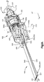
Figure 1A is a cut-away perspective view of a powered saw according to an embodiment of the present disclosure; -
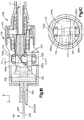
Figure 1B is a sectional side elevation view of a powered saw similar to the powered saw illustrated inFigure 1A , but constructed in accordance with an alternative embodiment; -
Figure 1C is a side elevation view of an eccentric shaft of the powered saw illustrated inFigures 1A-B ; -
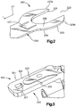
Figure 2 is a perspective view of a proximal end of a saw blade according to an embodiment of the present disclosure; -
Figure 3 is a perspective view of a mounting member according to an embodiment of the present disclosure; -
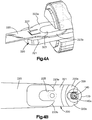
Figure 4A is a cut away perspective view of the connection mechanism according to an embodiment of the present disclosure, illustrating the blade shown infigure 2 engaged with connection mechanism shown infigure 3 ; -
Figure 4B is a bottom plan view of the connection mechanism illustrated inFigure 4A ; -
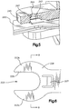
Figure 5 is a sectional perspective view of a portion of connection mechanism according to an embodiment of the present disclosure; -
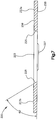
Figure 6 is a bottom plan view of the proximal end of a saw blade shown inFig. 2 ; and -
Figure 7 is a cross-section of the proximal end of the saw blade along the line B-B inFig. 6 . - Referring to
Fig. 1A , apowered saw 100 having a drive location that is configured to support amotor drive 110 that is operably connected toeccentric shaft 140 via gearing. The powered saw 100 can include themotor drive 110, for instance at the drive location as illustrated inFig. 1A , or the drive location can define a receptacle 111 (seeFig. 1B ) that is configured to receive, for instance removably receive, a drive, such as a motor drive. Thesaw 100 can include a handle portion orhandpiece 102 and a cuttingportion 104 spaced from thehandle portion 102 along the longitudinal direction L. The saw 100 can include ahousing 107 for carrying at least a portion of thedrive 110 and gearing. Thehousing 107 can at least partially define thereceptacle 111. - The
saw 100, or cuttingportion 104, can include afirst blade 220 and asecond blade 240. The first andsecond blade proximal end 252 and 352, respectively, each of which is configured to attach to the saw (detailed below), and a distal end 254 and 354, respectively, spaced from theproximal end 252 and 352 along the longitudinal direction L when the blades are attached to thesaw 100. The proximal ends of the blades can define respective blade attachment portions. Thefirst blade 220 includes a first orupper surface 256 and a second orlower surface 258 spaced from thefirst surface 256 along the transverse direction T. The transverse direction T can be substantially perpendicular to the longtidunal direction L of thesaw 100. The blades 220,240 can extend along the longtidunal direction L and have a transverse directional component. Further, thesecond blade 240 includes a first or upper surface 356 and a second or lower surface 358 spaced from the first surface 356 along the transverse direction T. Each respective blade surfaces extend between the proximal end 252,352 and the distal end 254,354 of theblades blades portion blade attachments saw 100. In order the cut an object, the first andsecond blades saw 100 so as to oscillate about a similar axis, or alternatively, about a different axes. For instance, the first andsecond blades -
Blades saw 100 byblade attachments blades blade attachments arms arms Figs. 1C and4B ) which surround the eccentric shaft 140 (see alsoFigure 1C ). Theeccentric shaft 140 is disposed along a transverse direction T, which is perpendicular to theblades blade attachments planetary gear 120 and a 90°gear transmission 130. - In use, torque is transferred from the
drive 110 via theplanetary gear 120 and the 90°gear transmission 130 to rotate theeccentric shaft 140 about acentral shaft axis 140a. As theshaft 140 rotates it converts rotational movement from thedrive 110 to oscillation of theblades blade attachments blade attachments central axes central shaft axis 140a, and can be disposed opposite each other such that thecentral shaft axis 140a is disposed between thecentral axes eccentric shaft 140 is configured such that, as it rotates, it moves the first pairs ofarms arms eccentric shaft 140 has acentral portion 150, a first offsetportion 152, and a second offsetportion 154. Thecentral portion 150 extends along thecentral shaft axis 140a. The first offsetportion 152 second offsetportions 154 extend along respective central offset axes (not shown) that lie in a similar plane with respective thecentral axes arms portion 154 and the second pair ofarms portion 152. Theblades central shaft axis 140a, that extends along the transverse direction T. For instance, thecentral shaft axis 140a can extend along the transverse direction T and is substantially perpendicular to the first blade surfaces 256 and 258, and/or the second blade surfaces 356 and 358. Theblades blade attachments blades - The
planetary gear 120 achieves a reduction of the speed of the drive transmitted to the blades, and conversely an increase in torque. The ratio of reduction of speed along a direction from thedrive 110 to theblades gear transmission 130 can include a first orinput gear 131, which can be a bevel gear, and a second oroutput gear 133, which can be a bevel gear, that is intermeshed with thefirst gear 131. Theplanetary gear 120 can be disposed between the drive location (and thus the motor drive 110) and the 90°gear transmission 130. The 90° gear transmission can be disposed between theplanetary gear 120 and theeccentric shaft 140. - During operation, the
first gear 131 rotates about a first axis of rotation 331 (Fig. 1A ), and thesecond gear 133 rotates about a second axis ofrotation 333 that is angularly offset, for instance oriented substantially 90°, with respect to the first axis ofrotation 331. Thefirst gear 131 is coupled to thedrive 110. Thefirst gear 131 is configured to be driven to rotate by thedrive 110 along the first axis of rotation, and thesecond gear 133 is coupled to theshaft 140, so as to drive the shaft to rotate about a corresponding axis of rotation that can be parallel or coincident with the second axis of rotation. Thus, thefirst gear 131 is disposed between thesecond gear 133 and thedrive 110, and thesecond gear 133 is disposed between theshaft 140 and thefirst gear 131. Thesecond gear 133 is configured to drive theeccentric shaft 140 to rotate, thereby causing theblades first gear 131 can be sized smaller than thesecond gear 133, and thus can have fewer teeth than thesecond gear 133. Accordingly, thesecond gear 133 rotates at a speed that is less than that of thefirst gear 131, and at a torque that is proportionally greater than that of thefirst gear 131. In accordance with one embodiment, the gear ratio can be as desired, for instance between 1:1.1 and 1:2. In accordance with the illustrated embodiment, the gear ratio can be 1:1.3846. The gear reduction of the 90° gear transmission produces a corresponding reduction of speed that is equal to the gear ratio, and a corresponding increase in torque output that is equal to the gear ratio. When the ratio of reduction of speed of the planetary gear is 1:3.9474 and the ratio of reduction of speed of the 90° gear transmission is 1:1.3846, the powered saw 100 produces a ratio of reduction in speed from thedrive 110 to theeccentric shaft 140 of approximately ratio 1:5.4656. Although a planetary gear is illustrated, it would also be possible to use a bevel gear in its place. - The
planetary gear 120 acts to provide high torque to theblades central shaft axis 140a, there is limited, if any, resulting vibration of the bone or countertorque transmitted to thehandpiece 102. Since limited, if any, counter-torque is transmitted to the handpiece, handling of the tool is made easier, resulting in a more precise cut. The entry speed of the saw blades is between 2000 to 3000 rpm. - In an alternative embodiment of the saw, the planetary or bevel gear may be omitted so that there is a direct drive between the 90°
gear transmission 130 and theblades Figure 1B , the powered saw 100 defines areceptacle 111 that can provide the drive location. Thereceptacle 111 is configured to receive a drive, such as a motor drive, at the drive location, the drive operable to rotate at a desired speed and produce a corresponding torque output. The powered saw 100 can be devoid of the planetary gear illustrated inFig. 1A , such that the speed and torque output from the motor drive is communicated to thefirst gear 131 of the 90°gear transmission 130. Thus, thefirst gear 131 can be driven to rotate at substantially the same speed as the motor drive at substantially the same torque as is output from the motor drive. As described above, thefirst gear 131 can be sized smaller than thesecond gear 133, and thus can have fewer teeth than thesecond gear 133. Accordingly, thesecond gear 133 rotates at a speed that is less than that of thefirst gear 131, and at a torque that is proportionally greater than that of thefirst gear 131. In accordance with one embodiment, the gear ratio can be as desired, for instance between and including approximately 1:1.1 and approximately 1:5, including approximately 1:1.3846, approximately 1:1.5, or any suitable alternative gear ratio as desired. The gear reduction of the 90°gear transmission 130 produces a corresponding reduction of speed that is equal to the gear ratio, and a corresponding increase in torque output that is equal to the gear ratio. Furthermore, in accordance with the embodiment illustrated inFigure 1B , the gear ratio of the 90°gear transmission 130 can define the gear ratio, and thus the speed reduction and torque increase, between the motor drive and the blades. - The output speed of the oscillation of the
blades - The
blades corresponding blade attachments saw 100 is provided that can have two identically configured blades. It should be appreciated that the blades can have different configurations as needed. For purpose of illustrating the configuration of first andsecond blades blade 220 will be further detailed below. It should be appreciated that the features described herein with respect to thefirst blade 220 are applicable to thesecond blade 240. Further, the features described herein regarding theblade attachment 320 are applicable to theblade attachment 340. - Referring to
Figs. 2, 3 and6 , theproximal end 252 of the blade 220 a spanner shapedhead 222. The spanner shapedhead 222 defines anopening 223 that extends along a longitudinal direction L. For instance, thehead 222 has twoarms arms opening 223. Theproximal end 252 of theblade 220 also comprises aprojection 227 that extends from the surface 258 (or 256) ofblade 220 along a transverse direction T. Theprojection 227 can be a latch which is milled out from theblade 220 and is bent downwards along the transverse direction T so that it is resiliently biased into a position in which it extends from thesurface 258 of theblade 220. - Referring to
Fig. 3 , theblade attachment 320 includes a mountingmember 321, for instance a mountingportion 321. The mountingportion 321 has a receivingsurface 322, and a raisedportion 323, for instance a portion that raised relative to the receivingsurface 322 along the transverse direction T. The raisedportion 323 is configured to correspond to the shape of theopening 223 ofblade 220 shown inFig. 2 . Theblade 220 can thus be slid into engagement with the receivingsurface 322 such that thearms portion 323 of the mounting portion 321 (Fig. 4A ) as shown infigure 4 . - Referring to
Figs. 2 ,6 and7 , theblade 240 can define aninner surface 225, the at least partially defines theopening 223. Theinner surface 225 can extend from theupper blade surface 256 to thelower blade surface 258, and along the spaced apartarms inner surface 225 ofarms blade 220 are angled relative to thelower surface 258, or plane of theblade 220. In an embodiment, the angle of theinner surface 225 relative to the plane of the blade is about 60°. As can be seen inFig. 3 , the mountingportion 321 can also define anouter surface 325 that extends from the raisedportion 323 to the receivingsurface 322. Theouter surface 325 of the raisedportion 323 is angled relative the raisedportion 323 to define a complementarily angle with respect to theinner surface 225 ofblade 220. Thus, theouter surface 325 of the raisedportion 323 and theinner surface 225 of thearms blade opening 223 is slid into close engagement with the raisedportion 323 as shown infigures 4A-B . As a result, movement relative to the surface of the blade is effectively prevented so that vibration between the two blade surfaces is minimized. - Referring to
Figs. 2 and 3 , the receivingsurface 322 has anaperture 327 that is positioned distal to the raisedportion 323 along the longitudinal direction L. Theaperture 327 is configured to receive at least a portion of theprojection 227. Theaperture 327 can act as a latching surface, against which theprojection 227 of theblade 220 latches once theblade 220 has been slid into the position shown infigures 4A-B . From this position, theblade 220 cannot be moved axially, for instance, along the longitudinal direction L out of engagement with the mountingportion 321. The latchingprojection 227 is resiliently biased towards the latching surface. However, the latchingprojection 227 is accessible through theaperture 327 by means of an opening in the opposing side of the mountingportion 321 to the receiving surface 322 (see forexample opening 349 inFig. 5 ). As a result, it is possible to release the latchingprojection 227 from its first position in theaperture 327 into which it is resiliently biased as shown infigure 4A and 4B , into a second position in which theprojection 227 no longer latches against the latching surface. When projection is in the second position, theblade 220 is no longer prevented from moving axially relative to the mountingportion 321 and can be moved out of engagement therewith. Thus, theblade 220 is readily removable from engagement with the mountingmember 321, and thus, the powered saw 100. As shown inFig. 5 , thesecond blade 240 can have a latchingprojection 247 which can engage theaperture 347 of theblade attachment 340. - It will of course be understood that the present disclosure has been described above purely by way of example, and that modifications of detail can be made within the scope of the present disclosure.
- Preferred embodiments of the invention are specified in the following paragraphs:
- 1. A saw, comprising:
- a drive;
- a first blade configured to oscillate about an axis perpendicular to a plane defined by a surface of the blade;
- a second blade configured to oscillate about an axis perpendicular to the plane in a direction opposite to that of the first blade, and
- a gearing disposed between the drive and the first and second blades, the gearing configured to reduce the speed transmitted from the drive to the blades.
- 2. A saw according to para 1, further comprising an eccentric drive shaft rotatably connected to the drive, wherein the eccentric drive shaft acts to cause the first and second blades to oscillate.
- 3. A saw according to para 2, wherein the eccentric drive shaft is perpendicular to the plane of each blade.
- 4. A saw according to any one of the preceding paras, wherein the gearing comprises a planetary or a 90° gear transmission.
- 5. A saw according to para 4, wherein the gearing comprises a 90° gear transmission such that the drive is substantially parallel with the plane.
- 6. A saw according to para 4 to 5, wherein the gearing provides a gear ratio of approximately 1:1.5.
- 7. A saw according to para 5, wherein the gearing comprises the 90° gear transmission that includes a first bevel gear configured to be coupled to a drive, a second bevel gear that is coupled to the eccentric drive shaft, the first gear having fewer teeth than the second gear.
- 8. A saw according to para 6, wherein the 90° gear transmission provides a gear ratio of 1:1.3846.
- 9. A saw according to any one of paras 5 to 8, wherein the gearing further comprises the planetary gear transmission disposed between the drive and the 90° gear transmission.
- 10. A saw according to para 9, wherein the planetary gear defines a gear ratio of 1:3.9474 that defines a reduction of speed along a direction from the drive to the first and second blades.
- 11. A saw according to any one of the preceding paras, wherein the blades oscillate about the same axis.
- 12. A saw according to any one of the preceding, wherein the blades are removably attached to the saw.
- 13. A saw blade comprising:
- a cutting edge at a distal end;
- an attachment portion at a proximal end of the blade, the attachment portion configured to connect the blade to a saw; and
- a projection extending from the blade and resiliently biased into a position in which it extends away from a surface of the blade.
- 14. A connection mechanism for connecting a saw blade to a saw comprising:
- a mounting portion defining a receiving surface and a raised portion;
- a blade defining an opening;
- wherein a surface of the blade can be slid into engagement with the receiving surface and the raised portion is received in the opening of the blade in the plane of the blade.
- 15. A saw according to any of paras 1 to 12, wherein the first and second blades comprise a blade according to para 13.
- 16. A saw according to any of paras 1 to 12, further comprising a connection mechanism according to para 14.
Claims (13)
- A method of cutting, comprising steps of:transferring torque from a drive (110) to first and second parallel blades (220, 240) to oscillate the first and second blades (220, 240) in opposite directions relative to one another; andreducing a speed of oscillation of the first and second blades (220, 240) via a gearing (120, 130) that is connected between the drive (110) and the first and second blades (220, 240).
- The method of claim 1, wherein the step of transferring torque comprises transferring torque from the drive (110) to an eccentric drive shaft (140) which causes the first and second cutting blades (220, 240) to oscillate.
- The method of any one of claims 1 and 2, further comprising a step of transmitting rotation, via a 90° gear transmission (130) of the gearing (120, 130), between the drive (110) and the blades (220, 240).
- The method of any one of claims 1 to 3, further comprising a step of transmitting motion, via a planetary gear (120) or bevel gear of the gearing (120, 130), between the drive (110) and the blades (220, 240).
- The method of any one of claims 1 to 4, wherein the drive (110) is a motor drive.
- The method of any one of claims 1 to 5, wherein the transferring step comprises causing the first blade (220) to oscillate about an axis that is perpendicular to a plane defined by a surface of the first blade (220) and causing the second blade (240) to oscillate about an axis that is perpendicular to a plane defined by a surface of the second blade (240), in a direction opposite to that of the first blade (220).
- The method of claim 1, wherein the step of transmitting rotation comprises:causing the drive (110) to rotate a first gear (131) of a 90° gearing (130) about a first axis; andcausing the first gear (131) to rotate a second gear (133) of the 90° gearing (130) about a second axis, perpendicular to the first axis, so as to drive an eccentric shaft (140) to rotate, thereby causing the first and second blades (220, 240) to reciprocally oscillate.
- The method of claim 7, wherein the first gear (131) has fewer teeth than the second gear (133).
- The method of claim 7, wherein the 90° gearing (130) provides a gear ratio between and including approximately 1:1.1 and approximately 1:5.
- The method of claim 7, wherein the 90° gearing (130) provides a gear ratio of approximately 1:1.3846 or approximately 1:1.5.
- The method of claim 4, wherein the planetary gear (120) defines a gear ratio of approximately 1:3.9474 that defines a reduction of speed along a direction from the drive (110) to the first and second blades (220, 240).
- The method of any one of claims 1 to 11, wherein the step of transferring torque comprises causing the first and second blades (220, 240) to oscillate at a speed between approximately 7000 and 10000 rpm.
- The method of any one of claims 1 to 11, wherein the step of transferring torque comprises causing the first and second blades (220, 240) to oscillate at a speed between approximately 8000 and 10000 rpm.
Applications Claiming Priority (4)
| Application Number | Priority Date | Filing Date | Title |
|---|---|---|---|
| US201261670914P | 2012-07-12 | 2012-07-12 | |
| US201261692869P | 2012-08-24 | 2012-08-24 | |
| EP13737781.8A EP2872052B1 (en) | 2012-07-12 | 2013-07-09 | A saw, a saw blade and a connection mechanism |
| PCT/US2013/049632 WO2014011577A1 (en) | 2012-07-12 | 2013-07-09 | A saw, a saw blade and a connection mechanism |
Related Parent Applications (2)
| Application Number | Title | Priority Date | Filing Date |
|---|---|---|---|
| EP13737781.8A Division EP2872052B1 (en) | 2012-07-12 | 2013-07-09 | A saw, a saw blade and a connection mechanism |
| EP13737781.8A Division-Into EP2872052B1 (en) | 2012-07-12 | 2013-07-09 | A saw, a saw blade and a connection mechanism |
Publications (2)
| Publication Number | Publication Date |
|---|---|
| EP3453340A2 true EP3453340A2 (en) | 2019-03-13 |
| EP3453340A3 EP3453340A3 (en) | 2019-05-22 |
Family
ID=48794244
Family Applications (2)
| Application Number | Title | Priority Date | Filing Date |
|---|---|---|---|
| EP13737781.8A Active EP2872052B1 (en) | 2012-07-12 | 2013-07-09 | A saw, a saw blade and a connection mechanism |
| EP18191649.5A Withdrawn EP3453340A3 (en) | 2012-07-12 | 2013-07-09 | A saw, a saw blade and a connection mechanism |
Family Applications Before (1)
| Application Number | Title | Priority Date | Filing Date |
|---|---|---|---|
| EP13737781.8A Active EP2872052B1 (en) | 2012-07-12 | 2013-07-09 | A saw, a saw blade and a connection mechanism |
Country Status (9)
| Country | Link |
|---|---|
| US (4) | US9629638B2 (en) |
| EP (2) | EP2872052B1 (en) |
| JP (1) | JP2015527911A (en) |
| KR (1) | KR102160396B1 (en) |
| CN (1) | CN104470447B (en) |
| BR (1) | BR112015000632B1 (en) |
| CA (1) | CA2878822C (en) |
| IN (1) | IN2014DN10608A (en) |
| WO (1) | WO2014011577A1 (en) |
Families Citing this family (23)
| Publication number | Priority date | Publication date | Assignee | Title |
|---|---|---|---|---|
| US20120198709A1 (en) * | 2009-10-12 | 2012-08-09 | Arbortech Industries Ltd | Oscillating blade improvement |
| US9027452B2 (en) * | 2011-12-27 | 2015-05-12 | Robert Bosch Gmbh | Jab saw accessory tool for an oscillating tool |
| US12324590B2 (en) * | 2019-07-01 | 2025-06-10 | Fusion Orthopedics, Llc | Surgical instruments including a set of cutting burrs for performing an osteotomy |
| CA2925926C (en) | 2013-10-10 | 2021-11-16 | Arbortech Industries Limited | Tool mechanism and tools using same |
| EP3083172A1 (en) * | 2013-12-20 | 2016-10-26 | Robert Bosch GmbH | Oscillating mechanism for a power tool |
| KR101568836B1 (en) | 2014-08-18 | 2015-11-12 | 주식회사 아임삭 | Oscillating saw device |
| CN104398288B (en) * | 2014-10-31 | 2017-02-15 | 舒捷医疗科技(苏州)有限公司 | Medical saw and clamping head thereof |
| US10342553B2 (en) | 2015-01-21 | 2019-07-09 | Stryker European Holdings I, Llc | Surgical sagittal saw and complementary blade with features that fixedly hold the blade static to the saw |
| EP3572013B1 (en) | 2015-02-19 | 2025-03-19 | Stryker Corporation | Surgical saw and complementary saw blade, the blade including lock teeth formed out of material that deforms when the blade is secured to the saw |
| CN105078539B (en) * | 2015-07-22 | 2019-01-11 | 苏州益诺斯医疗科技有限公司 | Medical reciprocating saw |
| GB201618450D0 (en) * | 2016-11-01 | 2016-12-14 | Genius Ip Ltd | Apparatus for causing oscillating motion of a saw blade, a saw bland, and a method of attaching the saw blade |
| JP6852152B2 (en) | 2016-06-13 | 2021-03-31 | シンセス・ゲーエムベーハーSynthes GmbH | Saw gear set |
| CN107693087B (en) * | 2017-11-07 | 2023-11-03 | 北京蒙太因医疗器械有限公司 | Pendulum saw for osteotomy |
| CN108969052A (en) * | 2018-06-29 | 2018-12-11 | 杭州光启医疗科技发展有限公司 | A kind of dedicated orthopaedics saw of bone surgery |
| CN110801261B (en) * | 2019-11-22 | 2021-06-18 | 上海龙慧医疗科技有限公司 | Double-moving-piece fine cutting swing saw blade for orthopedic surgery |
| CN116018108A (en) * | 2020-09-04 | 2023-04-25 | 比恩-空气控股有限公司 | Balance system for micro saws |
| CN112315538A (en) * | 2020-10-05 | 2021-02-05 | 德清创赢机械科技有限公司 | Small medical bone saw |
| CN112690866A (en) * | 2020-12-23 | 2021-04-23 | 刘慧珊 | Full-automatic orthopedics saw |
| US12508034B2 (en) * | 2022-10-14 | 2025-12-30 | Smith & Nephew, Inc. | Dual-blade tipped oscillating saw |
| KR102742204B1 (en) | 2022-10-26 | 2024-12-12 | 임예찬 | Square hole punching cutter for vibrating cutter |
| CN117582263B (en) * | 2024-01-15 | 2024-04-19 | 诺美伊创医疗科技(成都)有限公司 | Medical plane blade |
| US20260102829A1 (en) * | 2024-10-15 | 2026-04-16 | Henry Morris | Dual-Bladed Multi-Tool Device |
| US12446894B1 (en) * | 2025-04-22 | 2025-10-21 | Stryker European Operations Limited | Saw blade for use in performing a medical procedure |
Citations (1)
| Publication number | Priority date | Publication date | Assignee | Title |
|---|---|---|---|---|
| US5846244A (en) | 1995-09-18 | 1998-12-08 | Exactech, Inc. | Counter-balanced oscillating surgical saw |
Family Cites Families (41)
| Publication number | Priority date | Publication date | Assignee | Title |
|---|---|---|---|---|
| US1940855A (en) * | 1931-06-25 | 1933-12-26 | Friedman Hugo | Knife |
| US2520145A (en) * | 1946-07-22 | 1950-08-29 | Kenneth W Horton | Broken blade hack saw attachment |
| US2676630A (en) * | 1950-02-23 | 1954-04-27 | Parker Mfg Company | Blade retaining construction for hacksaws |
| US2931674A (en) * | 1958-04-23 | 1960-04-05 | Clarence J Davies | Separable splice for endless flexible bands |
| GB1455566A (en) * | 1973-01-08 | 1976-11-17 | Nat Res Dev | Saws and blades therefor |
| US4106181A (en) * | 1976-08-09 | 1978-08-15 | American Safety Equipment Corporation | Quick release mechanism for oscillating saw blade |
| US4386609A (en) * | 1979-12-17 | 1983-06-07 | Minnesota Mining And Manufacturing Company | Attaching assembly for an osteotomy saw blade |
| US4872452A (en) * | 1989-01-09 | 1989-10-10 | Minnesota Mining And Manufacturing Company | Bone rasp |
| US5272812A (en) * | 1990-11-13 | 1993-12-28 | Becton, Dickinson And Company | Surgical blade holder and blade combination |
| US5392910A (en) * | 1994-07-21 | 1995-02-28 | Transidyne General Corporation | Package for a device having a sharp cutting edge |
| US5697158A (en) * | 1995-12-21 | 1997-12-16 | Minnesota Mining And Manufacturing Company | Orthopedic surgical device having a rotatable portion and lock |
| DE19614832C1 (en) | 1996-04-15 | 1997-04-17 | Aesculap Ag | Saw for surgical purposes |
| US5722168A (en) * | 1996-07-29 | 1998-03-03 | Huang; Jung Hua | Saw blade securing mechanism |
| US6007541A (en) * | 1998-01-09 | 1999-12-28 | Midas Rex, L.P. | Dual-bladed reciprocating bone saw |
| US6113618A (en) * | 1999-01-13 | 2000-09-05 | Stryker Corporation | Surgical saw with spring-loaded, low-noise cutting blade |
| JP4938979B2 (en) | 2002-05-31 | 2012-05-23 | ヴァイダケア、コーパレイシャン | Apparatus and method for accessing bone marrow |
| USD492412S1 (en) * | 2003-03-07 | 2004-06-29 | De Soutter Medical Ltd. | Surgical saw blade |
| AU2003207922A1 (en) * | 2003-03-13 | 2004-09-30 | Warsaw Orthopedic, Inc. | Vertebral endplate preparation tool kit |
| US7497860B2 (en) | 2004-07-09 | 2009-03-03 | Stryker Corporation | Surgical sagittal saw including a handpiece and a removable blade assembly, the blade assembly including a guide bar, a blade head capable of oscillatory movement and a drive rod for actuating the blade head |
| US7691106B2 (en) * | 2005-09-23 | 2010-04-06 | Synvasive Technology, Inc. | Transverse acting surgical saw blade |
| US20080027449A1 (en) | 2006-07-28 | 2008-01-31 | Depuy Products, Inc. | Adapters to convert output motion of orthopaedic bone saws and bone drills |
| CA2704695A1 (en) * | 2006-11-15 | 2008-05-22 | Mark Goldin | Tissue cavitation device and method |
| US20110026434A1 (en) | 2008-02-18 | 2011-02-03 | Koninklijke Philips Electronics N.V. | Localization of luminaires |
| US8685028B2 (en) * | 2009-08-21 | 2014-04-01 | Infinesse Corporation | Reciprocating surgical saws with blade assemblies |
| US20110046627A1 (en) * | 2009-08-21 | 2011-02-24 | Chong Chol Kim | Reciprocating Surgical Saws With Blade Assemblies |
| RU2013151797A (en) * | 2011-04-21 | 2015-05-27 | Инфьюжн Брэндс, Инк. | MULTI-FUNCTIONAL SAW OF BIDIRECTIONAL VIBRATION ACTION |
| USD716944S1 (en) * | 2011-08-03 | 2014-11-04 | Synvasive Technology, Inc. | Surgical saw blade hub |
| WO2013020115A2 (en) * | 2011-08-04 | 2013-02-07 | Milwaukee Electric Tool Corporation | Reciprocating saw blade |
| US9302405B2 (en) * | 2011-10-28 | 2016-04-05 | Robert Bosch Gmbh | Planer accessory tool for an oscillating power tool |
| US8936597B2 (en) * | 2012-02-06 | 2015-01-20 | Medtronic Ps Medical, Inc. | Deflectable finger connection feature on surgical saw blade |
| US8888784B1 (en) * | 2012-08-29 | 2014-11-18 | Christopher B. Murphy | Dual bladed surgical saw and method of use |
| US9561569B2 (en) * | 2012-12-31 | 2017-02-07 | Robert Bosch Tool Corporation | Wobble drive for an oscillating tool |
| US9629641B2 (en) * | 2013-06-26 | 2017-04-25 | AOD Holdings, LLC | Rasp |
| CA158744S (en) * | 2014-04-18 | 2015-04-28 | Nanjing Jinmeida Tools Co Ltd | Oscillating saw blade |
| US10456848B1 (en) * | 2014-10-01 | 2019-10-29 | Lee Bornschlegel | Reciprocating saw blade assembly |
| EP3572013B1 (en) * | 2015-02-19 | 2025-03-19 | Stryker Corporation | Surgical saw and complementary saw blade, the blade including lock teeth formed out of material that deforms when the blade is secured to the saw |
| US10456142B2 (en) * | 2016-06-03 | 2019-10-29 | Mako Surgical Corp. | Surgical saw and saw blade for use therewith |
| US10265778B2 (en) * | 2017-01-16 | 2019-04-23 | Black & Decker Inc. | Accessories for oscillating power tools |
| USD853816S1 (en) * | 2017-03-30 | 2019-07-16 | Aesculap Ag | Combination receptacle and saw blade |
| DE102017112872B4 (en) * | 2017-06-12 | 2019-03-28 | Aesculap Ag | sawblade |
| CN110087841B (en) * | 2017-07-18 | 2021-07-13 | Um工业株式会社 | folding saw |
-
2013
- 2013-07-09 CN CN201380037084.XA patent/CN104470447B/en active Active
- 2013-07-09 WO PCT/US2013/049632 patent/WO2014011577A1/en not_active Ceased
- 2013-07-09 KR KR1020157002989A patent/KR102160396B1/en active Active
- 2013-07-09 CA CA2878822A patent/CA2878822C/en active Active
- 2013-07-09 EP EP13737781.8A patent/EP2872052B1/en active Active
- 2013-07-09 JP JP2015521706A patent/JP2015527911A/en active Pending
- 2013-07-09 US US13/937,267 patent/US9629638B2/en active Active
- 2013-07-09 IN IN10608DEN2014 patent/IN2014DN10608A/en unknown
- 2013-07-09 BR BR112015000632-9A patent/BR112015000632B1/en active IP Right Grant
- 2013-07-09 EP EP18191649.5A patent/EP3453340A3/en not_active Withdrawn
-
2017
- 2017-03-24 US US15/468,745 patent/US10052109B2/en active Active
-
2018
- 2018-07-17 US US16/037,294 patent/US11109871B2/en active Active
-
2021
- 2021-08-04 US US17/393,443 patent/US12042155B2/en active Active
Patent Citations (1)
| Publication number | Priority date | Publication date | Assignee | Title |
|---|---|---|---|---|
| US5846244A (en) | 1995-09-18 | 1998-12-08 | Exactech, Inc. | Counter-balanced oscillating surgical saw |
Also Published As
| Publication number | Publication date |
|---|---|
| BR112015000632B1 (en) | 2021-06-08 |
| BR112015000632A2 (en) | 2017-06-27 |
| US10052109B2 (en) | 2018-08-21 |
| US9629638B2 (en) | 2017-04-25 |
| CN104470447A (en) | 2015-03-25 |
| US20140018811A1 (en) | 2014-01-16 |
| KR102160396B1 (en) | 2020-10-05 |
| WO2014011577A1 (en) | 2014-01-16 |
| US11109871B2 (en) | 2021-09-07 |
| US20180317936A1 (en) | 2018-11-08 |
| JP2015527911A (en) | 2015-09-24 |
| CA2878822A1 (en) | 2014-01-16 |
| KR20150036379A (en) | 2015-04-07 |
| US20210369286A1 (en) | 2021-12-02 |
| US20170196570A1 (en) | 2017-07-13 |
| EP2872052B1 (en) | 2018-10-10 |
| CA2878822C (en) | 2021-07-13 |
| EP3453340A3 (en) | 2019-05-22 |
| IN2014DN10608A (en) | 2015-09-11 |
| EP2872052A1 (en) | 2015-05-20 |
| US12042155B2 (en) | 2024-07-23 |
| CN104470447B (en) | 2018-04-27 |
Similar Documents
| Publication | Publication Date | Title |
|---|---|---|
| US12042155B2 (en) | Saw, a saw blade, a connection mechanism and associated methods | |
| EP2964109B3 (en) | Surgical saw mount and blade | |
| CN111836589A (en) | Rotary oscillating and linear reciprocating surgical tool | |
| JP6852152B2 (en) | Saw gear set | |
| US9579105B2 (en) | Sagittal saw | |
| KR101730566B1 (en) | Electric Driving Tool with Vibration Reduction Function | |
| GB2457249A (en) | A rotationally reciprocating cutting tool | |
| CN110801261B (en) | Double-moving-piece fine cutting swing saw blade for orthopedic surgery | |
| CN115956977A (en) | A grinding device for the distal end of the femoral condyle | |
| CN102950332A (en) | Portable cutting machine | |
| CN223958852U (en) | Bone cutting pendulum saw | |
| US11844531B2 (en) | Balancing system for a micro-saw | |
| CN121512619A (en) | Surgical components for attachment to surgical accessory tools |
Legal Events
| Date | Code | Title | Description |
|---|---|---|---|
| PUAI | Public reference made under article 153(3) epc to a published international application that has entered the european phase |
Free format text: ORIGINAL CODE: 0009012 |
|
| STAA | Information on the status of an ep patent application or granted ep patent |
Free format text: STATUS: THE APPLICATION HAS BEEN PUBLISHED |
|
| AC | Divisional application: reference to earlier application |
Ref document number: 2872052 Country of ref document: EP Kind code of ref document: P |
|
| AK | Designated contracting states |
Kind code of ref document: A2 Designated state(s): AL AT BE BG CH CY CZ DE DK EE ES FI FR GB GR HR HU IE IS IT LI LT LU LV MC MK MT NL NO PL PT RO RS SE SI SK SM TR |
|
| PUAL | Search report despatched |
Free format text: ORIGINAL CODE: 0009013 |
|
| AK | Designated contracting states |
Kind code of ref document: A3 Designated state(s): AL AT BE BG CH CY CZ DE DK EE ES FI FR GB GR HR HU IE IS IT LI LT LU LV MC MK MT NL NO PL PT RO RS SE SI SK SM TR |
|
| RIC1 | Information provided on ipc code assigned before grant |
Ipc: B27B 19/00 20060101ALI20190417BHEP Ipc: B23D 61/00 20060101ALI20190417BHEP Ipc: A61B 17/14 20060101AFI20190417BHEP Ipc: B27B 5/30 20060101ALI20190417BHEP |
|
| STAA | Information on the status of an ep patent application or granted ep patent |
Free format text: STATUS: REQUEST FOR EXAMINATION WAS MADE |
|
| 17P | Request for examination filed |
Effective date: 20191113 |
|
| RBV | Designated contracting states (corrected) |
Designated state(s): AL AT BE BG CH CY CZ DE DK EE ES FI FR GB GR HR HU IE IS IT LI LT LU LV MC MK MT NL NO PL PT RO RS SE SI SK SM TR |
|
| STAA | Information on the status of an ep patent application or granted ep patent |
Free format text: STATUS: EXAMINATION IS IN PROGRESS |
|
| 17Q | First examination report despatched |
Effective date: 20230822 |
|
| STAA | Information on the status of an ep patent application or granted ep patent |
Free format text: STATUS: THE APPLICATION IS DEEMED TO BE WITHDRAWN |
|
| 18D | Application deemed to be withdrawn |
Effective date: 20240103 |