EP3453193B1 - Gruppenanrufeinrichtung in einem gruppenkommunikationssystem - Google Patents
Gruppenanrufeinrichtung in einem gruppenkommunikationssystem Download PDFInfo
- Publication number
- EP3453193B1 EP3453193B1 EP16722112.6A EP16722112A EP3453193B1 EP 3453193 B1 EP3453193 B1 EP 3453193B1 EP 16722112 A EP16722112 A EP 16722112A EP 3453193 B1 EP3453193 B1 EP 3453193B1
- Authority
- EP
- European Patent Office
- Prior art keywords
- mbms bearer
- control node
- node
- group
- call setup
- Prior art date
- Legal status (The legal status is an assumption and is not a legal conclusion. Google has not performed a legal analysis and makes no representation as to the accuracy of the status listed.)
- Active
Links
Images


Classifications
-
- H—ELECTRICITY
- H04—ELECTRIC COMMUNICATION TECHNIQUE
- H04W—WIRELESS COMMUNICATION NETWORKS
- H04W76/00—Connection management
- H04W76/40—Connection management for selective distribution or broadcast
- H04W76/45—Connection management for selective distribution or broadcast for Push-to-Talk [PTT] or Push-to-Talk over cellular [PoC] services
-
- H—ELECTRICITY
- H04—ELECTRIC COMMUNICATION TECHNIQUE
- H04W—WIRELESS COMMUNICATION NETWORKS
- H04W4/00—Services specially adapted for wireless communication networks; Facilities therefor
- H04W4/06—Selective distribution of broadcast services, e.g. multimedia broadcast multicast service [MBMS]; Services to user groups; One-way selective calling services
- H04W4/10—Push-to-Talk [PTT] or Push-On-Call services
Definitions
- Embodiments presented herein relate to methods, a control node, a client node, computer programs, and a computer program product for group call setup in a group communications system.
- communications networks there may be a challenge to obtain good performance and capacity for a given communications protocol, its parameters and the physical environment in which the communications network is deployed.
- group communication means that the same information or media is delivered to multiple client nodes.
- group communication systems e.g., Push-To-Talk (PTT) systems
- PTT Push-To-Talk
- client nodes receiving the same media constitute a group of client nodes.
- These client nodes may be located at different locations. If many client nodes are located within the same area, multicast or broadcast based transmission using e.g., Multicast-Broadcast Multimedia Services (MBMS) is efficient for communications to the group of client nodes, because communications resources such as time and frequency resources are shared among client nodes. If client nodes are spread out over a large geographical area it can be more efficient to use unicast transmission for communications to the group of client nodes.
- MBMS Multicast-Broadcast Multimedia Services
- Fig. 1 is a schematic diagram illustrating a communications system 100 where embodiments presented herein can be applied.
- the communications system 100 is assumed to provide services for group communication and may hence be regarded as a group communications system.
- the group communications system 100 is, according to some aspects, a push to talk (PTT) system.
- PTT push to talk
- the communications system 100 comprises a radio access network 120, a core network 130, and a service network 140.
- the communications system 100 further comprises at least one control node 200 and at least one client node 300a, 300b, 300c.
- the at least one control node 200 may be provided in, or installed on, a radio access network node 110 or in another entity or device in the radio access network 120, in an entity or device of the core network 130, or in an entity or device of the service network 140.
- the at least one control node 200 could implement the functionality of a group communication application server (GCS AS).
- GCS AS group communication application server
- Each client node 300a, 300b, 300c may be provided in, or installed on, a respective wireless device 150a, 150b, 150c.
- Each client node 300a, 300b, 300c can be part of a group 160a, 160b of client nodes node 300a, 300b, 300c.
- client nodes 300a, 300b are part of one group 160a
- client nodes 300b, 300c are part of another group 160b.
- the radio access network 120 is operatively connected to the core network 130 which in turn is operatively connected to the service network 140.
- the radio access network node 110 thereby enables the wireless devices 150a, 150b, 150C, and hence the client nodes 300a, 300b, 300c, to access services and exchange data as provided by the service network 140.
- wireless devices 150a, 150b, 150c include, but are not limited to, mobile stations, mobile phones, handsets, wireless local loop phones, user equipment (UE), smartphones, laptop computers, and tablet computers.
- radio access network nodes 110 include, but are not limited to, radio base stations, base transceiver stations, node Bs, evolved node Bs, and access points.
- the communications system 100 may comprise a plurality of radio access network nodes 110, each providing network access to a plurality of wireless devices 150a, 150b, 150c.
- the herein disclosed embodiments are not limited to any particular number of radio access network nodes 110, client nodes 300a, 300b, 300c, groups 160a, 160b, or wireless devices 150a, 150b, 150c.
- a first transmission mode is known as Multicast-Broadcast Single Frequency Network (MBSFN).
- MBSFN Multicast-Broadcast Single Frequency Network
- a group of adjacent radio access network nodes 110 transmits the same signal simultaneously on the same frequency.
- SIR Signal-to-Interference Ratio
- SC-PTM Single Cell Point to Multipoint
- SC-PTM was introduced in 3GPP E-UTRAN in Rel-13. In this transmission mode only one radio access network node 110 transmit the data. This transmission mode does not provide the benefit of improved SIR due to contributions from neighboring radio access network nodes as in MBSFN.
- SC-PTM can be used with finer geographically granularity since SC-PTM will be used only in cells where the wireless devices 150a, 150b, 150c are located.
- MBSFN MBMS Control Channel
- SC-MCCH SC-MCCH
- the performance requirements for a call setup is typically shorter than 300 ms.
- MBSFN this implies that the MBSFN transmission must be pre-activated in the network and announced to the wireless device 150a, 150b, 150c prior the call setup.
- the wireless device 150a, 150b, 150c needs to constantly monitor the MBMS bearer on the MBSFN transmission to listen for any call setup message.
- SC-PTM the transmission can be started by the call setup requests, and it is still possible to reach the call setup performance requirements.
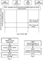
- Fig. 2 illustrating a signalling diagram according to prior art.
- S301 When using MBMS (with MBSFN transmission) two preparation activities are performed. First, an MBMS bearer is activated. This will enable media to be sent over the network and broadcasted over the radio access network to the client node 300a, 300b in the wireless device 150a, 150b. In a 3GPP LTE network this is initiated in a Broadcast Multicast Service Center (BMSC) as defined in 3GPP TS 23.246 v13.3.0 . Second, the client node 300a, 300b is informed of the service being broadcasted over the MBMS bearer. This is required so that the client node 300a, 300b knows how to receive the media over the MBMS bearer. This procedure is commonly known as a service announcement procedure and is defined in 3GPP TS 26.346 v13.3.0.
- BMSC Broadcast Multicast Service Center
- the client node 300a, 300b then monitors the MBMS bearer and waits for group call setup messages.
- Group Communication and specifically PTT calls are typically short with long periods of silence between the calls.
- S302 A new group call setup message initiated for client node 300b, it is first sent to the control node 200, and the control node 200 forwards the setup message of the MBMS bearer to receiving client nodes, as represented by client node 300a.
- S303 Group call media is sent from client node 300b to the control node 200, and the control node 200 broadcasts the media on the MBMS bearer so that the media can be received by client node 300a.
- a group communication system that uses MBMS to transmit group calls over an MBSFN must pre-activate the MBMS bearer, and the wireless device must constantly be monitoring the radio frames that are allocated for the MBMS bearer.
- the group call setup messages as well as the group call media will be transmitted on the pre-activated bearer.
- the constant monitoring of the MBMS bearer is power consuming.
- the patent application relates to a 3GPP compliant system includes a radio access network (RAN) partitioned into a plurality MBMS services areas, wherein each MBMS service area has a plurality of MBMS bearers established a priori for transporting media streams.
- RAN radio access network
- An infrastructure device receives a request to transmit a media stream to a communication group, wherein the request to transmit is received after the MBMS bearers were established: determines a MBMS bearer in a MBMS service area to assign to transport the media stream: generates a MBMS connect message that binds the communication group to the assigned MBMS bearer, wherein the MBMS connect message includes an identifier for the communication group and an identifier for the assigned MBMS bearer: and sends the MBMS connect message to members of the communication group.
- An object of embodiments herein is to provide efficient group call setup in a group communications system.
- the invention is defined by the subject matter of the independent claims which define a method performed by a client node and the client node apparatus.
- Advantageous enhancements are subject to the dependent claims.
- the method and the client node provide efficient group call setup in a group communications system.
- the method and the client node combine the benefits of using MBSFN transmission, which gives improved SIR, and SC-PTM, which provides a quicker setup time for a MBMS bearer.
- the wireless device hosting the client node does not constantly need to monitor an active MBSFN. This reduces power consumption i.e. save battery, and still provides the possibility to fast call setup in a group call transmitted on a MBSFN.
- the MBMS bearer on the SC-PTM will only be activated in the cells where wireless devices interested in the call are located.
- An MBSFN can be pre-activated and notified to the client nodes.
- the MBSFN transmission is known to the client nodes 300a, 300b, 300c, however the client nodes 300a, 300b, 300c do not need to constantly listen for call setup messages on the MBMS bearer with MBSFN transmission and furthermore the client nodes 300a, 300b, 300c can stay in idle mode and still reach target performance requirements.
- the group call setup message can be initiated on another MBMS bearer that utilizes an SC-PTM transmission to notify the client nodes 300a, 300b, 300c about the call.
- the group call setup message can include an MBMS bearer identity of the bearer that will be used to transfer the group call media.
- the identified MBMS bearer can use MBSFN transmission.
- the embodiments disclosed herein thus relate to mechanisms for group call setup in a group communications system 100.
- a control node 200 a method performed by the control node 200, a computer program product comprising code, for example in the form of a computer program, that when run on processing circuitry of the control node 200, causes the control node 200 to perform the method.
- a client node 300a a method performed by the client node 300a, and a computer program product comprising code, for example in the form of a computer program, that when run on processing circuitry of the client node 300a, causes the client node 300a to perform the method.
- Figs. 3 and 4 are flow charts illustrating embodiments of methods for group call setup in a group communications system 100 as performed by the control node 200.
- Figs. 5 and 6 are flow charts illustrating embodiments of methods for group call setup in a group communications system 100 as performed by the client node 300a.
- the methods are advantageously provided as computer programs 420a, 420b.
- Fig. 3 illustrating a method for group call setup in a group communications system 100 as performed by the control node 200 according to an embodiment.
- control node 200 is therefore configured to perform step S106: S106: The control node 200 obtains a need for transmission of group call media to a group 160a, 160b of client nodes 300a, 300b, 300c in the group communications system 100.
- the control node 200 then activates a previously announced MBMS bearer.
- the control node 200 is thus configured to perform step S108: S108: The control node 200 activates a previously announced second MBMS bearer in response to having obtained the need.
- control node 200 can transmit group call setup message for future transmission of the group call media.
- the control node 200 is thus configured to perform step S110: S110: The control node 200 transmits a group call setup message on the second MBMS bearer.
- the group call setup message comprises at least an identity of a previously announced and activated first MBMS bearer.
- the control node 200 to quickly activate an MBMS bearer used for call setup messages.
- the setup time of this MBMS bearer will meet the performance requirements of group call setup procedures.
- the group call setup message comprises an identifier of a previously activated and announced MBMS bearer, which the client node 300a, 300b, 300c starts to monitor when the call setup message is received. This means that the client node 300a, 300b, 300c does not need to constantly monitor the MBMS bearer used for group communication when there are no active calls. This reduces power consumption in the wireless device 150a, 150b, 150c hosting the client node 300a, 300b, 300c.
- Fig. 4 illustrating methods for group call setup in a group communications system 100 as performed by the control node 200 according to further embodiments. It is assumed that steps S106, S108, S110 are performed as disclosed above and a thus repeated description thereof is therefore omitted.
- control node 200 may act before obtaining the need for transmission of group call media in step S106.
- the control node 200 is configured to announce and activate the first MBMS bearer as in step S102: S102: The control node 200 announces and activates the first MBMS bearer before obtaining the need (in step S106).
- control node 200 is configured to announce the second MBMS bearer as in step S104: S104: The control node 200 announces the second MBMS bearer before obtaining the need (in step S106).
- steps S102 and S104 are performed does not matter as long as both steps are performed before step S106.
- the need can be defined by a received group call setup message from one of the client nodes 300a, 300b, 300c.
- the need for transmission is obtained by receiving the group call setup message from one of the client nodes (300a, 300b, 300c.
- control node 200 may handle the transmission of the group call media.
- control node 200 is configured to handle the transmission of the group call media as in steps S112 and S114:
- At least step S114 is performed after the group call setup message in step S110 has been transmitted.
- Fig. 5 illustrating a method for group call setup in a group communications system 100 as performed by the client node 300a according to an embodiment.
- the control node 200 in step S108 activates a previously announced second MBMS bearer. It is here assumed that the client node 300a receives an indication of this activation. Hence, the client node 300a is configured to perform step S208: S208: The client node 300a receives system information indicating activation of a previously announced second MBMS bearer from the control node 200.
- the control node in step S110 transmits a group call setup message on the second MBMS bearer. It is here assumed that the client node 300a receives this group call setup message. Hence, the client node 300a is configured to perform step S212: S212: The client node 300a receives a group call setup message on the second MBMS bearer from the control node 200. As disclosed above the group call setup message comprises at least an identity of a previously announced and activated first MBMS bearer.
- Fig. 6 illustrating methods for group call setup in a group communications system 100 as performed by the client node 300a according to further embodiments. It is assumed that steps S208, S212 are performed as disclosed above and a thus repeated description thereof is therefore omitted.
- the control node 200 in step S102 announces and activates the first MBMS bearer. It can be assumed that the client node 300a receives an indication of this announcement and activation.
- the client node 300a is configured to perform step S202: S202: The client node 300a receives announcement and system information indicating activation of the first MBMS bearer from the control node 200 before receiving the activation of the second MBMS bearer (in step S208).
- the client node 300a determines not to monitor this first bearer.
- the client node 300a is configured to perform step S204: S204: The client node 300a determines not to monitor the first MBMS bearer upon receiving the system information indicating the activation of the first MBMS bearer (in step S202).
- the control node 200 in step S104 announces the second MBMS bearer. It can be assumed that the client node 300a receives an indication of this announcement.
- the client node 300a is configured to perform step S206: S206: The client node 300a receives announcement of the second MBMS bearer from the control node 200 before receiving the activation of the second MBMS bearer (in step S208).
- the client node 300a determines to monitor this second bearer.
- the client node 300a is configured to perform step S210: S210: The client node 300a determines to monitor the second MBMS bearer upon receiving the activation indication of the second MBMS bearer (in step S208).
- the client node 300a determines to monitor this first bearer.
- the client node 300a is configured to perform step S214: S214: The client node 300a determines to monitor the first MBMS bearer upon receiving the group call setup message (in step S212).
- control node 200 in step S114 broadcasts the group call media. It can be assumed that the client node 300a receives the group call media. Hence, according to an embodiment the client node 300a is configured to perform step S216: S216: The client node 300a receives group call media on the first MBMS bearer from the control node 200.
- the first MBMS bearer and the second MBMS bearer uses mutually different transmission modes.
- a first transmission mode can be used for the first MBMS bearer
- a second transmission mode can be used for the second MBMS bearer, where the second transmission mode is different from the first transmission mode.
- the second transmission mode can have shorter start-up time than the first transmission mode.
- the first MBMS bearer uses MBSFN transmission.
- the second MBMS bearer uses SC-PTM transmission.
- S401 When using MBMS (with MBSFN transmission) two preparation activities are performed. First, an MBMS bearer is activated. This will enable media to be sent over the network and broadcasted over the radio access network to the client node 300a, 300b in the wireless device 150a, 150b. In a 3GPP LTE network this is initiated in a Broadcast Multicast Service Center (BMSC) as defined in 3GPP TS 23.246 v13.3.0. Second, the client node 300a, 300b is informed of the service being broadcasted over the MBMS bearer.
- BMSC Broadcast Multicast Service Center
- the client node 300a, 300b does not need to immediately start monitoring the first MBMS bearer.
- the client node 300a, 300b could start to monitor the first MBMS bearer for a short period of time and acknowledge to the control node 200 that the client node 300a, 300b is able to monitor the first MBMS bearer.
- step S401 is to perform any of step S102, step S202, and S204.
- step S402 The control node 200 announces a second MBMS bearer (using SC-PTM transmission) is to the client node 300a, 300b. Note that the second MBMS bearer is not activated. It is only announced to the client node 300a, 300b that there could be a MBMS bearer started at any time with the purpose to send group call setup messages.
- One way to implement step S402 is to perform any of step S104 and step S206.
- step S403 The control node 200 obtains a need for transmission of group call media by receiving a group call setup message from client node 300b.
- One way to implement step S403 is to perform step S106.
- step S404 The control node 200 activates the previously announced second MBMS bearer using SC-PTM transmission.
- the activation request can be sent from the control node 200 to a broadcast multicast service centre (BM-SC) which sets up the MBMS bearer.
- BM-SC broadcast multicast service centre
- One way to implement step S404 is to perform any of step S108, step S208, step S210.
- step S405 The control node 200 transmits a group call setup message on the second MBMS bearer to the client node 300a. This message includes an identifier of the first MBMS bearer.
- One way to implement step S405 is to perform any of step S110 and step S212.
- step S406 The client node 300a (immediately) starts to monitor the first MBMS bearer.
- One way to implement step S406 is to perform step S214.
- step S407 Group call media is sent from client node 300b to the control node 200, and the control node 200 broadcasts the media on the first MBMS bearer so that the media can be received by client node 300a.
- One way to implement step S407 is to perform any of step S114 and step S216.
- Fig. 8 schematically illustrates, in terms of a number of functional units, the components of a control node 200 according to an embodiment.
- Processing circuitry 210 is provided using any combination of one or more of a suitable central processing unit (CPU), multiprocessor, microcontroller, digital signal processor (DSP), etc., capable of executing software instructions stored in a computer program product 410a (as in Fig. 12 ), e.g. in the form of a storage medium 230.
- the processing circuitry 210 may further be provided as at least one application specific integrated circuit (ASIC), or field programmable gate array (FPGA).
- ASIC application specific integrated circuit
- FPGA field programmable gate array
- the processing circuitry 210 is configured to cause the control node 200 to perform a set of operations, or steps, S102-S114, as disclosed above.
- the storage medium 230 may store the set of operations
- the processing circuitry 210 may be configured to retrieve the set of operations from the storage medium 230 to cause the control node 200 to perform the set of operations.
- the set of operations may be provided as a set of executable instructions.
- the processing circuitry 210 is thereby arranged to execute methods as herein disclosed.
- the storage medium 230 may also comprise persistent storage, which, for example, can be any single one or combination of magnetic memory, optical memory, solid state memory or even remotely mounted memory.
- the control node 200 may further comprise a communications interface 220 for communications at least with a client node 300a, 300b, 300c and preferably with entities and devices of the radio access network 120, the core network 130 and the service network 140.
- the communications interface 220 may comprise one or more transmitters and receivers, comprising analogue and digital components and a suitable number of antennas for wireless communications and ports for wireline communications.
- the processing circuitry 210 controls the general operation of the control node 200 e.g. by sending data and control signals to the communications interface 220 and the storage medium 230, by receiving data and reports from the communications interface 220, and by retrieving data and instructions from the storage medium 230.
- Other components, as well as the related functionality, of the control node 200 are omitted in order not to obscure the concepts presented herein.
- Fig. 9 schematically illustrates, in terms of a number of functional modules, the components of a control node 200 according to an embodiment.
- the control node 200 of Fig. 9 comprises a number of functional modules; an obtain module 210c configured to perform step S106, an activate module 210d configured to perform step S108, and a transmit module 210e configured to perform step S110.
- the control node 200 of Fig. 9 may further comprise a number of optional functional modules, such as any of an announce and activate module 210a configured to perform step S102, an announce module 210b configured to perform step S104, an obtain module 210f configured to perform step S112, and a broadcast module 210g configured to perform step S114.
- each functional module 210a-210g may be implemented in hardware or in software.
- one or more or all functional modules 210a-210g may be implemented by the processing circuitry 210, possibly in cooperation with functional units 220 and/or 230.
- the processing circuitry 210 may thus be arranged to from the storage medium 230 fetch instructions as provided by a functional module 210a-210g and to execute these instructions, thereby performing any steps of the control node 200 as disclosed herein.
- the control node 200 may be provided as a standalone device or as a part of at least one further device.
- the control node 200 may be provided in a node of the radio access network 120 or in a node of the core network 130 or in a node of the service network 140.
- functionality of the control node 200 may be distributed between at least two devices, or nodes. These at least two nodes, or devices, may either be part of the same network part (such as the radio access network or the core network or the service network) or may be spread between at least two such network parts.
- control node 200 may be implemented at the service layer of the protocol stack.
- instructions that are required to be performed in real time may be performed in a device, or node, operatively closer to the radio access network 120 than instructions that are not required to be performed in real time.
- at least part of the control node 200 may reside in the radio access network 120, such as in the radio access network node 110, for cases when embodiments as disclosed herein are performed in real time.
- a first portion of the instructions performed by the control node 200 may be executed in a first device, and a second portion of the of the instructions performed by the control node 200 may be executed in a second device; the herein disclosed embodiments are not limited to any particular number of devices on which the instructions performed by the control node 200 may be executed.
- the methods according to the herein disclosed embodiments are suitable to be performed by a control node 200 residing in a cloud computational environment. Therefore, although a single processing circuitry 210 is illustrated in Fig. 8 the processing circuitry 210 may be distributed among a plurality of devices, or nodes. The same applies to the functional modules 210a-210g of Fig. 9 and the computer program 420a of Fig. 12 (see below).
- Fig. 10 schematically illustrates, in terms of a number of functional units, the components of a client node 300a according to an embodiment.
- Processing circuitry 310 is provided using any combination of one or more of a suitable central processing unit (CPU), multiprocessor, microcontroller, digital signal processor (DSP), etc., capable of executing software instructions stored in a computer program product 410b (as in Fig. 12 ), e.g. in the form of a storage medium 330.
- the processing circuitry 310 may further be provided as at least one application specific integrated circuit (ASIC), or field programmable gate array (FPGA).
- ASIC application specific integrated circuit
- FPGA field programmable gate array
- the processing circuitry 310 is configured to cause the client node 300a to perform a set of operations, or steps, S202-S216, as disclosed above.
- the storage medium 330 may store the set of operations
- the processing circuitry 310 may be configured to retrieve the set of operations from the storage medium 330 to cause the client node 300a to perform the set of operations.
- the set of operations may be provided as a set of executable instructions.
- the processing circuitry 310 is thereby arranged to execute methods as herein disclosed.
- the storage medium 330 may also comprise persistent storage, which, for example, can be any single one or combination of magnetic memory, optical memory, solid state memory or even remotely mounted memory.
- the client node 300a may further comprise a communications interface 320 for communications at least with the control node 200 and preferably with entities and devices of the radio access network 120, the core network 130 and the service network 140.
- the communications interface 320 may comprise one or more transmitters and receivers, comprising analogue and digital components and a suitable number of antennas for wireless communications and ports for wireline communications.
- the processing circuitry 310 controls the general operation of the client node 300a e.g. by sending data and control signals to the communications interface 320 and the storage medium 330, by receiving data and reports from the communications interface 320, and by retrieving data and instructions from the storage medium 330.
- Other components, as well as the related functionality, of the client node 300a are omitted in order not to obscure the concepts presented herein.
- Fig. 11 schematically illustrates, in terms of a number of functional modules, the components of a client node 300a according to an embodiment.
- the client node 300a of Fig. 11 comprises a number of functional modules; a receive module 310d configured to perform step S208, and a receive module 310f configured to perform step S212.
- the client node 300a of Fig. 11 schematically illustrates, in terms of a number of functional modules, the components of a client node 300a according to an embodiment.
- the client node 300a of Fig. 11 comprises a number of functional modules; a receive module 310d configured to perform step S208, and a receive module 310f configured to perform step S212.
- 11 may further comprises a number of optional functional modules, such as any of a receive module 310a configured to perform step S202, a determine module 310b configured to perform step S204, a receive module 310c configured to perform step S206, a monitor module 310e configured to perform step S210, a monitor module 310g configured to perform step S214, and a receive module 310h configured to perform step S216.
- a receive module 310a configured to perform step S202
- a determine module 310b configured to perform step S204
- a receive module 310c configured to perform step S206
- a monitor module 310e configured to perform step S210
- a monitor module 310g configured to perform step S214
- a receive module 310h configured to perform step S216.
- each functional module 310a-310h may be implemented in hardware or in software.
- one or more or all functional modules 310a-310h may be implemented by the processing circuitry 310, possibly in cooperation with functional units 320 and/or 330.
- the processing circuitry 310 may thus be arranged to from the storage medium 330 fetch instructions as provided by a functional module 310a-310h and to execute these instructions, thereby performing any steps of the client node 300a as disclosed herein.
- the client node 300a may be provided as a standalone device or as a part of at least one further device.
- the client node 300a may be provided in a wireless device 150a.
- any processing circuitry, communications interface and storage medium of the wireless device 150a may be shared with the processing circuitry 310, communications interface 320 and storage medium 330 of the client node 300a. It is thus not necessary for the client node 300a to have its own processing circuitry 310, communications interface 320 and storage medium 330 as long as the processing circuitry, communications interface and storage medium of the wireless device 150a is configured to implement the functionality of the herein disclosed client node 300a.
- Fig. 12 shows one example of a computer program product 410a, 410b comprising computer readable means 430.
- a computer program 420a can be stored, which computer program 420a can cause the processing circuitry 210 and thereto operatively coupled entities and devices, such as the communications interface 220 and the storage medium 230, to execute methods according to embodiments described herein.
- the computer program 420a and/or computer program product 410a may thus provide means for performing any steps of the control node 200 as herein disclosed.
- a computer program 420b can be stored, which computer program 420b can cause the processing circuitry 310 and thereto operatively coupled entities and devices, such as the communications interface 320 and the storage medium 330, to execute methods according to embodiments described herein.
- the computer program 420b and/or computer program product 410b may thus provide means for performing any steps of the client node 300a as herein disclosed.
- the computer program product 410a, 410b is illustrated as an optical disc, such as a CD (compact disc) or a DVD (digital versatile disc) or a Blu-Ray disc.
- the computer program product 410a, 410b could also be embodied as a memory, such as a random access memory (RAM), a read-only memory (ROM), an erasable programmable read-only memory (EPROM), or an electrically erasable programmable read-only memory (EEPROM) and more particularly as a non-volatile storage medium of a device in an external memory such as a USB (Universal Serial Bus) memory or a Flash memory, such as a compact Flash memory.
- RAM random access memory
- ROM read-only memory
- EPROM erasable programmable read-only memory
- EEPROM electrically erasable programmable read-only memory
- EEPROM electrically erasable programmable read-only memory
- the computer program 420a, 420b is here schematically shown as
Landscapes
- Engineering & Computer Science (AREA)
- Computer Networks & Wireless Communication (AREA)
- Signal Processing (AREA)
- Multimedia (AREA)
- Mobile Radio Communication Systems (AREA)
Claims (9)
- Verfahren für Gruppenanrufaufbau in einem Gruppenkommunikationssystem (100), wobei das Verfahren durch einen Client-Knoten (300a) durchgeführt wird, wobei das Verfahren umfasst:Empfangen (S208) von Systeminformationen, die Aktivierung eines vorab bekanntgegebenen zweiten MBMS-Trägers angeben, von einem Steuerknoten (200);Empfangen (S212) einer Gruppenanrufaufbaunachricht auf dem zweiten MBMS-Träger vom Steuerknoten (200), wobei die Gruppenanrufaufbaunachricht mindestens eine Identität eines vorab bekanntgegebenen und aktivierten ersten MBMS-Trägers umfasstBestimmen (S210), den zweiten MBMS-Träger zu überwachen, nach Empfangen der Aktivierungsangabe des zweiten MBMS-Trägers.
- Verfahren nach Anspruch 1, weiter umfassend:
Empfangen (S202) von einer Bekanntgabe und Systeminformationen, die Aktivierung des ersten MBMS-Trägers angeben, vom Steuerknoten (200) vor Empfangen der Aktivierung des zweiten MBMS-Trägers. - Verfahren nach Anspruch 2, weiter umfassend:
Bestimmen (S204), den ersten MBMS-Träger nach Empfangen der Systeminformationen, welche die Aktivierung des ersten MBMS-Trägers angeben, nicht zu überwachen. - Verfahren nach Anspruch 2 oder 3, weiter umfassend:
Empfangen (S206) einer Bekanntgabe des zweiten MBMS-Trägers vom Steuerknoten (200) vor Empfangen der Aktivierung des zweiten MBMS-Trägers. - Verfahren nach einem der Ansprüche 1 bis 4, weiter umfassend:
Empfangen (S216) von Gruppenanrufmedien auf dem ersten MBMS-Träger vom Steuerknoten (200). - Verfahren nach einem der vorstehenden Ansprüche, wobei der erste MBMS-Träger und der zweite MBMS-Träger voneinander verschiedene Übertragungsmodi verwendet.
- Verfahren nach einem der vorstehenden Ansprüche, wobei der erste MBMS-Träger Multicast-Broadcast-Einzelfrequenznetzwerk ("Multicast-Broadcast Single-Frequency Network")-, MBSFN-, Übertragung verwendet.
- Verfahren nach einem der vorstehenden Ansprüche, wobei der zweite MBMS-Träger Einzelzellen-Point-to-Multipoint ("Single-Cell Point-to-Multipoint")-, SC-PTM-, Übertragung verwendet.
- Client-Knoten (300a) für Gruppenanrufaufbau in einem Gruppenkommunikationssystem (100), wobei der Client-Knoten (300a) Verarbeitungsschaltkreise (310) umfasst, wobei die Verarbeitungsschaltkreise konfiguriert sind, um den Client-Knoten (300a) dazu zu veranlassen:Systeminformationen, die Aktivierung eines vorab bekanntgegebenen zweiten MBMS-Trägers angeben, von einem Steuerknoten (200) zu empfangen;eine Gruppenanrufaufbaunachricht auf dem zweiten MBMS-Träger vom Steuerknoten (200) zu empfangen, wobei die Gruppenanrufaufbaunachricht mindestens eine Identität eines vorab bekanntgegebenen und aktivierten ersten MBMS-Trägers umfasst; undzu bestimmen, den zweiten MBMS-Träger zu überwachen, nach Empfangen der Aktivierungsangabe des zweiten MBMS-Trägers.
Applications Claiming Priority (1)
| Application Number | Priority Date | Filing Date | Title |
|---|---|---|---|
| PCT/EP2016/059792 WO2017190765A1 (en) | 2016-05-02 | 2016-05-02 | Group call setup in a group communications system |
Publications (2)
| Publication Number | Publication Date |
|---|---|
| EP3453193A1 EP3453193A1 (de) | 2019-03-13 |
| EP3453193B1 true EP3453193B1 (de) | 2019-11-27 |
Family
ID=55967232
Family Applications (1)
| Application Number | Title | Priority Date | Filing Date |
|---|---|---|---|
| EP16722112.6A Active EP3453193B1 (de) | 2016-05-02 | 2016-05-02 | Gruppenanrufeinrichtung in einem gruppenkommunikationssystem |
Country Status (3)
| Country | Link |
|---|---|
| US (1) | US20180124838A1 (de) |
| EP (1) | EP3453193B1 (de) |
| WO (1) | WO2017190765A1 (de) |
Families Citing this family (3)
| Publication number | Priority date | Publication date | Assignee | Title |
|---|---|---|---|---|
| CN110460603B (zh) * | 2019-08-15 | 2021-12-07 | 咪咕文化科技有限公司 | 多媒体文件的传输方法、终端、服务器、系统及存储介质 |
| CN111901764A (zh) * | 2020-04-24 | 2020-11-06 | 中兴通讯股份有限公司 | 广播/组播业务的管理方法、装置、电子设备和存储介质 |
| CN117896423B (zh) * | 2024-03-15 | 2024-05-14 | 四川博世科技信息产业有限公司 | 分布式智能呼叫管理系统及其控制方法 |
Family Cites Families (2)
| Publication number | Priority date | Publication date | Assignee | Title |
|---|---|---|---|---|
| US20120003969A1 (en) * | 2010-06-30 | 2012-01-05 | Motorola, Inc. | Method and apparatus for establishing a group call |
| US8861419B2 (en) * | 2010-12-29 | 2014-10-14 | Motorola Solutions, Inc. | Methods for binding and unbinding a MBMS bearer to a communication group in a 3GPP compliant system |
-
2016
- 2016-05-02 WO PCT/EP2016/059792 patent/WO2017190765A1/en not_active Ceased
- 2016-05-02 US US15/035,451 patent/US20180124838A1/en not_active Abandoned
- 2016-05-02 EP EP16722112.6A patent/EP3453193B1/de active Active
Non-Patent Citations (1)
| Title |
|---|
| None * |
Also Published As
| Publication number | Publication date |
|---|---|
| EP3453193A1 (de) | 2019-03-13 |
| US20180124838A1 (en) | 2018-05-03 |
| WO2017190765A1 (en) | 2017-11-09 |
Similar Documents
| Publication | Publication Date | Title |
|---|---|---|
| US12082078B2 (en) | MBMS bearer handling in a group communications system | |
| US12177745B2 (en) | MBMS bearer setup in a group communications system | |
| US20220295236A1 (en) | Method and apparatus for transmitting and receiving data in wireless communication system | |
| EP3453193B1 (de) | Gruppenanrufeinrichtung in einem gruppenkommunikationssystem | |
| EP3434032B1 (de) | Funkruf eines client-knotens in einem gruppenkommunikationssystem | |
| US11140656B2 (en) | Paging in a group communications system | |
| EP3403373A1 (de) | Handhabung eines mbms-trägers | |
| US20180302756A1 (en) | Group Metadata In A Group Communications System | |
| WO2018171892A1 (en) | Mbms bearer handling in a group communications system |
Legal Events
| Date | Code | Title | Description |
|---|---|---|---|
| STAA | Information on the status of an ep patent application or granted ep patent |
Free format text: STATUS: THE INTERNATIONAL PUBLICATION HAS BEEN MADE |
|
| PUAI | Public reference made under article 153(3) epc to a published international application that has entered the european phase |
Free format text: ORIGINAL CODE: 0009012 |
|
| STAA | Information on the status of an ep patent application or granted ep patent |
Free format text: STATUS: REQUEST FOR EXAMINATION WAS MADE |
|
| 17P | Request for examination filed |
Effective date: 20181017 |
|
| AK | Designated contracting states |
Kind code of ref document: A1 Designated state(s): AL AT BE BG CH CY CZ DE DK EE ES FI FR GB GR HR HU IE IS IT LI LT LU LV MC MK MT NL NO PL PT RO RS SE SI SK SM TR |
|
| AX | Request for extension of the european patent |
Extension state: BA ME |
|
| DAV | Request for validation of the european patent (deleted) | ||
| DAX | Request for extension of the european patent (deleted) | ||
| GRAP | Despatch of communication of intention to grant a patent |
Free format text: ORIGINAL CODE: EPIDOSNIGR1 |
|
| STAA | Information on the status of an ep patent application or granted ep patent |
Free format text: STATUS: GRANT OF PATENT IS INTENDED |
|
| INTG | Intention to grant announced |
Effective date: 20190828 |
|
| GRAS | Grant fee paid |
Free format text: ORIGINAL CODE: EPIDOSNIGR3 |
|
| GRAA | (expected) grant |
Free format text: ORIGINAL CODE: 0009210 |
|
| STAA | Information on the status of an ep patent application or granted ep patent |
Free format text: STATUS: THE PATENT HAS BEEN GRANTED |
|
| AK | Designated contracting states |
Kind code of ref document: B1 Designated state(s): AL AT BE BG CH CY CZ DE DK EE ES FI FR GB GR HR HU IE IS IT LI LT LU LV MC MK MT NL NO PL PT RO RS SE SI SK SM TR |
|
| REG | Reference to a national code |
Ref country code: GB Ref legal event code: FG4D |
|
| REG | Reference to a national code |
Ref country code: CH Ref legal event code: EP |
|
| REG | Reference to a national code |
Ref country code: AT Ref legal event code: REF Ref document number: 1208091 Country of ref document: AT Kind code of ref document: T Effective date: 20191215 |
|
| REG | Reference to a national code |
Ref country code: DE Ref legal event code: R096 Ref document number: 602016025062 Country of ref document: DE |
|
| REG | Reference to a national code |
Ref country code: IE Ref legal event code: FG4D |
|
| REG | Reference to a national code |
Ref country code: NL Ref legal event code: MP Effective date: 20191127 |
|
| REG | Reference to a national code |
Ref country code: LT Ref legal event code: MG4D |
|
| PG25 | Lapsed in a contracting state [announced via postgrant information from national office to epo] |
Ref country code: GR Free format text: LAPSE BECAUSE OF FAILURE TO SUBMIT A TRANSLATION OF THE DESCRIPTION OR TO PAY THE FEE WITHIN THE PRESCRIBED TIME-LIMIT Effective date: 20200228 Ref country code: LT Free format text: LAPSE BECAUSE OF FAILURE TO SUBMIT A TRANSLATION OF THE DESCRIPTION OR TO PAY THE FEE WITHIN THE PRESCRIBED TIME-LIMIT Effective date: 20191127 Ref country code: NO Free format text: LAPSE BECAUSE OF FAILURE TO SUBMIT A TRANSLATION OF THE DESCRIPTION OR TO PAY THE FEE WITHIN THE PRESCRIBED TIME-LIMIT Effective date: 20200227 Ref country code: NL Free format text: LAPSE BECAUSE OF FAILURE TO SUBMIT A TRANSLATION OF THE DESCRIPTION OR TO PAY THE FEE WITHIN THE PRESCRIBED TIME-LIMIT Effective date: 20191127 Ref country code: SE Free format text: LAPSE BECAUSE OF FAILURE TO SUBMIT A TRANSLATION OF THE DESCRIPTION OR TO PAY THE FEE WITHIN THE PRESCRIBED TIME-LIMIT Effective date: 20191127 Ref country code: LV Free format text: LAPSE BECAUSE OF FAILURE TO SUBMIT A TRANSLATION OF THE DESCRIPTION OR TO PAY THE FEE WITHIN THE PRESCRIBED TIME-LIMIT Effective date: 20191127 Ref country code: FI Free format text: LAPSE BECAUSE OF FAILURE TO SUBMIT A TRANSLATION OF THE DESCRIPTION OR TO PAY THE FEE WITHIN THE PRESCRIBED TIME-LIMIT Effective date: 20191127 Ref country code: BG Free format text: LAPSE BECAUSE OF FAILURE TO SUBMIT A TRANSLATION OF THE DESCRIPTION OR TO PAY THE FEE WITHIN THE PRESCRIBED TIME-LIMIT Effective date: 20200227 |
|
| PG25 | Lapsed in a contracting state [announced via postgrant information from national office to epo] |
Ref country code: RS Free format text: LAPSE BECAUSE OF FAILURE TO SUBMIT A TRANSLATION OF THE DESCRIPTION OR TO PAY THE FEE WITHIN THE PRESCRIBED TIME-LIMIT Effective date: 20191127 Ref country code: IS Free format text: LAPSE BECAUSE OF FAILURE TO SUBMIT A TRANSLATION OF THE DESCRIPTION OR TO PAY THE FEE WITHIN THE PRESCRIBED TIME-LIMIT Effective date: 20200327 Ref country code: HR Free format text: LAPSE BECAUSE OF FAILURE TO SUBMIT A TRANSLATION OF THE DESCRIPTION OR TO PAY THE FEE WITHIN THE PRESCRIBED TIME-LIMIT Effective date: 20191127 |
|
| PG25 | Lapsed in a contracting state [announced via postgrant information from national office to epo] |
Ref country code: AL Free format text: LAPSE BECAUSE OF FAILURE TO SUBMIT A TRANSLATION OF THE DESCRIPTION OR TO PAY THE FEE WITHIN THE PRESCRIBED TIME-LIMIT Effective date: 20191127 |
|
| PG25 | Lapsed in a contracting state [announced via postgrant information from national office to epo] |
Ref country code: EE Free format text: LAPSE BECAUSE OF FAILURE TO SUBMIT A TRANSLATION OF THE DESCRIPTION OR TO PAY THE FEE WITHIN THE PRESCRIBED TIME-LIMIT Effective date: 20191127 Ref country code: PT Free format text: LAPSE BECAUSE OF FAILURE TO SUBMIT A TRANSLATION OF THE DESCRIPTION OR TO PAY THE FEE WITHIN THE PRESCRIBED TIME-LIMIT Effective date: 20200419 Ref country code: DK Free format text: LAPSE BECAUSE OF FAILURE TO SUBMIT A TRANSLATION OF THE DESCRIPTION OR TO PAY THE FEE WITHIN THE PRESCRIBED TIME-LIMIT Effective date: 20191127 Ref country code: RO Free format text: LAPSE BECAUSE OF FAILURE TO SUBMIT A TRANSLATION OF THE DESCRIPTION OR TO PAY THE FEE WITHIN THE PRESCRIBED TIME-LIMIT Effective date: 20191127 Ref country code: ES Free format text: LAPSE BECAUSE OF FAILURE TO SUBMIT A TRANSLATION OF THE DESCRIPTION OR TO PAY THE FEE WITHIN THE PRESCRIBED TIME-LIMIT Effective date: 20191127 Ref country code: CZ Free format text: LAPSE BECAUSE OF FAILURE TO SUBMIT A TRANSLATION OF THE DESCRIPTION OR TO PAY THE FEE WITHIN THE PRESCRIBED TIME-LIMIT Effective date: 20191127 |
|
| REG | Reference to a national code |
Ref country code: DE Ref legal event code: R097 Ref document number: 602016025062 Country of ref document: DE |
|
| PG25 | Lapsed in a contracting state [announced via postgrant information from national office to epo] |
Ref country code: SM Free format text: LAPSE BECAUSE OF FAILURE TO SUBMIT A TRANSLATION OF THE DESCRIPTION OR TO PAY THE FEE WITHIN THE PRESCRIBED TIME-LIMIT Effective date: 20191127 Ref country code: SK Free format text: LAPSE BECAUSE OF FAILURE TO SUBMIT A TRANSLATION OF THE DESCRIPTION OR TO PAY THE FEE WITHIN THE PRESCRIBED TIME-LIMIT Effective date: 20191127 |
|
| REG | Reference to a national code |
Ref country code: AT Ref legal event code: MK05 Ref document number: 1208091 Country of ref document: AT Kind code of ref document: T Effective date: 20191127 |
|
| PLBE | No opposition filed within time limit |
Free format text: ORIGINAL CODE: 0009261 |
|
| STAA | Information on the status of an ep patent application or granted ep patent |
Free format text: STATUS: NO OPPOSITION FILED WITHIN TIME LIMIT |
|
| 26N | No opposition filed |
Effective date: 20200828 |
|
| PG25 | Lapsed in a contracting state [announced via postgrant information from national office to epo] |
Ref country code: SI Free format text: LAPSE BECAUSE OF FAILURE TO SUBMIT A TRANSLATION OF THE DESCRIPTION OR TO PAY THE FEE WITHIN THE PRESCRIBED TIME-LIMIT Effective date: 20191127 Ref country code: PL Free format text: LAPSE BECAUSE OF FAILURE TO SUBMIT A TRANSLATION OF THE DESCRIPTION OR TO PAY THE FEE WITHIN THE PRESCRIBED TIME-LIMIT Effective date: 20191127 Ref country code: AT Free format text: LAPSE BECAUSE OF FAILURE TO SUBMIT A TRANSLATION OF THE DESCRIPTION OR TO PAY THE FEE WITHIN THE PRESCRIBED TIME-LIMIT Effective date: 20191127 |
|
| PG25 | Lapsed in a contracting state [announced via postgrant information from national office to epo] |
Ref country code: MC Free format text: LAPSE BECAUSE OF FAILURE TO SUBMIT A TRANSLATION OF THE DESCRIPTION OR TO PAY THE FEE WITHIN THE PRESCRIBED TIME-LIMIT Effective date: 20191127 Ref country code: IT Free format text: LAPSE BECAUSE OF FAILURE TO SUBMIT A TRANSLATION OF THE DESCRIPTION OR TO PAY THE FEE WITHIN THE PRESCRIBED TIME-LIMIT Effective date: 20191127 Ref country code: CH Free format text: LAPSE BECAUSE OF NON-PAYMENT OF DUE FEES Effective date: 20200531 Ref country code: LI Free format text: LAPSE BECAUSE OF NON-PAYMENT OF DUE FEES Effective date: 20200531 |
|
| REG | Reference to a national code |
Ref country code: BE Ref legal event code: MM Effective date: 20200531 |
|
| PG25 | Lapsed in a contracting state [announced via postgrant information from national office to epo] |
Ref country code: LU Free format text: LAPSE BECAUSE OF NON-PAYMENT OF DUE FEES Effective date: 20200502 |
|
| PG25 | Lapsed in a contracting state [announced via postgrant information from national office to epo] |
Ref country code: IE Free format text: LAPSE BECAUSE OF NON-PAYMENT OF DUE FEES Effective date: 20200502 Ref country code: FR Free format text: LAPSE BECAUSE OF NON-PAYMENT OF DUE FEES Effective date: 20200531 |
|
| PG25 | Lapsed in a contracting state [announced via postgrant information from national office to epo] |
Ref country code: BE Free format text: LAPSE BECAUSE OF NON-PAYMENT OF DUE FEES Effective date: 20200531 |
|
| PG25 | Lapsed in a contracting state [announced via postgrant information from national office to epo] |
Ref country code: TR Free format text: LAPSE BECAUSE OF FAILURE TO SUBMIT A TRANSLATION OF THE DESCRIPTION OR TO PAY THE FEE WITHIN THE PRESCRIBED TIME-LIMIT Effective date: 20191127 Ref country code: MT Free format text: LAPSE BECAUSE OF FAILURE TO SUBMIT A TRANSLATION OF THE DESCRIPTION OR TO PAY THE FEE WITHIN THE PRESCRIBED TIME-LIMIT Effective date: 20191127 Ref country code: CY Free format text: LAPSE BECAUSE OF FAILURE TO SUBMIT A TRANSLATION OF THE DESCRIPTION OR TO PAY THE FEE WITHIN THE PRESCRIBED TIME-LIMIT Effective date: 20191127 |
|
| PG25 | Lapsed in a contracting state [announced via postgrant information from national office to epo] |
Ref country code: MK Free format text: LAPSE BECAUSE OF FAILURE TO SUBMIT A TRANSLATION OF THE DESCRIPTION OR TO PAY THE FEE WITHIN THE PRESCRIBED TIME-LIMIT Effective date: 20191127 |
|
| PGFP | Annual fee paid to national office [announced via postgrant information from national office to epo] |
Ref country code: DE Payment date: 20250529 Year of fee payment: 10 |
|
| PGFP | Annual fee paid to national office [announced via postgrant information from national office to epo] |
Ref country code: GB Payment date: 20250527 Year of fee payment: 10 |