EP3452982B1 - Feature suppression in dark field or phase contrast x-ray imaging - Google Patents
Feature suppression in dark field or phase contrast x-ray imaging Download PDFInfo
- Publication number
- EP3452982B1 EP3452982B1 EP17725187.3A EP17725187A EP3452982B1 EP 3452982 B1 EP3452982 B1 EP 3452982B1 EP 17725187 A EP17725187 A EP 17725187A EP 3452982 B1 EP3452982 B1 EP 3452982B1
- Authority
- EP
- European Patent Office
- Prior art keywords
- feature
- image
- ray
- dark field
- phase contrast
- Prior art date
- Legal status (The legal status is an assumption and is not a legal conclusion. Google has not performed a legal analysis and makes no representation as to the accuracy of the status listed.)
- Active
Links
- 238000003384 imaging method Methods 0.000 title claims description 44
- 230000001629 suppression Effects 0.000 title claims description 32
- 210000000988 bone and bone Anatomy 0.000 claims description 67
- 238000012545 processing Methods 0.000 claims description 57
- 238000000034 method Methods 0.000 claims description 30
- 238000009792 diffusion process Methods 0.000 claims description 24
- 238000004590 computer program Methods 0.000 claims description 17
- 210000004072 lung Anatomy 0.000 claims description 15
- 230000033001 locomotion Effects 0.000 description 17
- 230000005855 radiation Effects 0.000 description 13
- 238000010521 absorption reaction Methods 0.000 description 10
- 230000011218 segmentation Effects 0.000 description 10
- 230000000694 effects Effects 0.000 description 8
- 210000000038 chest Anatomy 0.000 description 6
- 230000001427 coherent effect Effects 0.000 description 6
- 238000002601 radiography Methods 0.000 description 5
- 230000003287 optical effect Effects 0.000 description 4
- GNFTZDOKVXKIBK-UHFFFAOYSA-N 3-(2-methoxyethoxy)benzohydrazide Chemical compound COCCOC1=CC=CC(C(=O)NN)=C1 GNFTZDOKVXKIBK-UHFFFAOYSA-N 0.000 description 3
- 238000001514 detection method Methods 0.000 description 3
- 238000005516 engineering process Methods 0.000 description 3
- 241001465754 Metazoa Species 0.000 description 2
- 241000699666 Mus <mouse, genus> Species 0.000 description 2
- 241000699670 Mus sp. Species 0.000 description 2
- XUIMIQQOPSSXEZ-UHFFFAOYSA-N Silicon Chemical compound [Si] XUIMIQQOPSSXEZ-UHFFFAOYSA-N 0.000 description 2
- 230000001419 dependent effect Effects 0.000 description 2
- 238000010586 diagram Methods 0.000 description 2
- 230000006870 function Effects 0.000 description 2
- LFEUVBZXUFMACD-UHFFFAOYSA-H lead(2+);trioxido(oxo)-$l^{5}-arsane Chemical compound [Pb+2].[Pb+2].[Pb+2].[O-][As]([O-])([O-])=O.[O-][As]([O-])([O-])=O LFEUVBZXUFMACD-UHFFFAOYSA-H 0.000 description 2
- 239000000463 material Substances 0.000 description 2
- 238000005259 measurement Methods 0.000 description 2
- 230000029058 respiratory gaseous exchange Effects 0.000 description 2
- 239000000523 sample Substances 0.000 description 2
- 229910052710 silicon Inorganic materials 0.000 description 2
- 239000010703 silicon Substances 0.000 description 2
- 239000007779 soft material Substances 0.000 description 2
- 210000004872 soft tissue Anatomy 0.000 description 2
- 239000000758 substrate Substances 0.000 description 2
- 230000003936 working memory Effects 0.000 description 2
- FGUUSXIOTUKUDN-IBGZPJMESA-N C1(=CC=CC=C1)N1C2=C(NC([C@H](C1)NC=1OC(=NN=1)C1=CC=CC=C1)=O)C=CC=C2 Chemical compound C1(=CC=CC=C1)N1C2=C(NC([C@H](C1)NC=1OC(=NN=1)C1=CC=CC=C1)=O)C=CC=C2 FGUUSXIOTUKUDN-IBGZPJMESA-N 0.000 description 1
- 208000006545 Chronic Obstructive Pulmonary Disease Diseases 0.000 description 1
- 206010016654 Fibrosis Diseases 0.000 description 1
- 241000282412 Homo Species 0.000 description 1
- 208000019693 Lung disease Diseases 0.000 description 1
- 239000011358 absorbing material Substances 0.000 description 1
- 238000010420 art technique Methods 0.000 description 1
- 230000009286 beneficial effect Effects 0.000 description 1
- 239000012472 biological sample Substances 0.000 description 1
- 230000005540 biological transmission Effects 0.000 description 1
- 230000000747 cardiac effect Effects 0.000 description 1
- 238000011976 chest X-ray Methods 0.000 description 1
- 238000010276 construction Methods 0.000 description 1
- 230000004761 fibrosis Effects 0.000 description 1
- 230000004907 flux Effects 0.000 description 1
- 210000004907 gland Anatomy 0.000 description 1
- 230000001939 inductive effect Effects 0.000 description 1
- 238000009434 installation Methods 0.000 description 1
- 238000002697 interventional radiology Methods 0.000 description 1
- 238000009607 mammography Methods 0.000 description 1
- 238000009659 non-destructive testing Methods 0.000 description 1
- 230000000737 periodic effect Effects 0.000 description 1
- 230000010363 phase shift Effects 0.000 description 1
- 230000001902 propagating effect Effects 0.000 description 1
- 239000007787 solid Substances 0.000 description 1
- 210000001519 tissue Anatomy 0.000 description 1
- 238000003325 tomography Methods 0.000 description 1
- 238000012546 transfer Methods 0.000 description 1
- 230000000007 visual effect Effects 0.000 description 1
Images


Classifications
-
- G—PHYSICS
- G06—COMPUTING; CALCULATING OR COUNTING
- G06T—IMAGE DATA PROCESSING OR GENERATION, IN GENERAL
- G06T5/00—Image enhancement or restoration
-
- A—HUMAN NECESSITIES
- A61—MEDICAL OR VETERINARY SCIENCE; HYGIENE
- A61B—DIAGNOSIS; SURGERY; IDENTIFICATION
- A61B6/00—Apparatus for radiation diagnosis, e.g. combined with radiation therapy equipment
- A61B6/46—Apparatus for radiation diagnosis, e.g. combined with radiation therapy equipment with special arrangements for interfacing with the operator or the patient
- A61B6/461—Displaying means of special interest
- A61B6/463—Displaying means of special interest characterised by displaying multiple images or images and diagnostic data on one display
-
- A—HUMAN NECESSITIES
- A61—MEDICAL OR VETERINARY SCIENCE; HYGIENE
- A61B—DIAGNOSIS; SURGERY; IDENTIFICATION
- A61B6/00—Apparatus for radiation diagnosis, e.g. combined with radiation therapy equipment
- A61B6/48—Diagnostic techniques
- A61B6/484—Diagnostic techniques involving phase contrast X-ray imaging
-
- A—HUMAN NECESSITIES
- A61—MEDICAL OR VETERINARY SCIENCE; HYGIENE
- A61B—DIAGNOSIS; SURGERY; IDENTIFICATION
- A61B6/00—Apparatus for radiation diagnosis, e.g. combined with radiation therapy equipment
- A61B6/50—Clinical applications
-
- A—HUMAN NECESSITIES
- A61—MEDICAL OR VETERINARY SCIENCE; HYGIENE
- A61B—DIAGNOSIS; SURGERY; IDENTIFICATION
- A61B6/00—Apparatus for radiation diagnosis, e.g. combined with radiation therapy equipment
- A61B6/52—Devices using data or image processing specially adapted for radiation diagnosis
- A61B6/5211—Devices using data or image processing specially adapted for radiation diagnosis involving processing of medical diagnostic data
- A61B6/5229—Devices using data or image processing specially adapted for radiation diagnosis involving processing of medical diagnostic data combining image data of a patient, e.g. combining a functional image with an anatomical image
- A61B6/5235—Devices using data or image processing specially adapted for radiation diagnosis involving processing of medical diagnostic data combining image data of a patient, e.g. combining a functional image with an anatomical image combining images from the same or different ionising radiation imaging techniques, e.g. PET and CT
-
- G06T3/14—
-
- G—PHYSICS
- G06—COMPUTING; CALCULATING OR COUNTING
- G06T—IMAGE DATA PROCESSING OR GENERATION, IN GENERAL
- G06T5/00—Image enhancement or restoration
- G06T5/50—Image enhancement or restoration by the use of more than one image, e.g. averaging, subtraction
-
- G—PHYSICS
- G06—COMPUTING; CALCULATING OR COUNTING
- G06T—IMAGE DATA PROCESSING OR GENERATION, IN GENERAL
- G06T7/00—Image analysis
- G06T7/30—Determination of transform parameters for the alignment of images, i.e. image registration
- G06T7/33—Determination of transform parameters for the alignment of images, i.e. image registration using feature-based methods
-
- G—PHYSICS
- G06—COMPUTING; CALCULATING OR COUNTING
- G06T—IMAGE DATA PROCESSING OR GENERATION, IN GENERAL
- G06T7/00—Image analysis
- G06T7/70—Determining position or orientation of objects or cameras
- G06T7/73—Determining position or orientation of objects or cameras using feature-based methods
- G06T7/74—Determining position or orientation of objects or cameras using feature-based methods involving reference images or patches
-
- G—PHYSICS
- G06—COMPUTING; CALCULATING OR COUNTING
- G06T—IMAGE DATA PROCESSING OR GENERATION, IN GENERAL
- G06T2207/00—Indexing scheme for image analysis or image enhancement
- G06T2207/10—Image acquisition modality
- G06T2207/10116—X-ray image
-
- G—PHYSICS
- G06—COMPUTING; CALCULATING OR COUNTING
- G06T—IMAGE DATA PROCESSING OR GENERATION, IN GENERAL
- G06T2207/00—Indexing scheme for image analysis or image enhancement
- G06T2207/20—Special algorithmic details
- G06T2207/20048—Transform domain processing
- G06T2207/20056—Discrete and fast Fourier transform, [DFT, FFT]
-
- G—PHYSICS
- G06—COMPUTING; CALCULATING OR COUNTING
- G06T—IMAGE DATA PROCESSING OR GENERATION, IN GENERAL
- G06T2207/00—Indexing scheme for image analysis or image enhancement
- G06T2207/30—Subject of image; Context of image processing
- G06T2207/30004—Biomedical image processing
-
- G—PHYSICS
- G06—COMPUTING; CALCULATING OR COUNTING
- G06T—IMAGE DATA PROCESSING OR GENERATION, IN GENERAL
- G06T2207/00—Indexing scheme for image analysis or image enhancement
- G06T2207/30—Subject of image; Context of image processing
- G06T2207/30004—Biomedical image processing
- G06T2207/30008—Bone
- G06T2207/30012—Spine; Backbone
-
- G—PHYSICS
- G06—COMPUTING; CALCULATING OR COUNTING
- G06T—IMAGE DATA PROCESSING OR GENERATION, IN GENERAL
- G06T2207/00—Indexing scheme for image analysis or image enhancement
- G06T2207/30—Subject of image; Context of image processing
- G06T2207/30004—Biomedical image processing
- G06T2207/30061—Lung
Definitions
- the present invention relates to an apparatus for feature suppression in dark field or phase contrast X-ray imaging, to a system for feature suppression in dark field or phase contrast X-ray imaging, and to a method for feature suppression in dark field or phase contrast X-ray imaging, as well as to a computer program element and a computer readable medium.
- WO2011/077334A1 and US 2014/140603 relate to bone suppression in X-ray radiograms.
- US 2015/150529 teaches transferring bone locations from standard X-ray to a phase contrast image for bone-related measurements.
- an apparatus for feature suppression in dark field or phase contrast X-ray imaging comprising:
- the input unit is configured to provide the processing unit with an X-ray attenuation image of a region of interest of an object.
- the input unit is also configured to provide the processing unit with a dark field or phase contrast X-ray image of the region of interest of the object.
- the processing unit is configured to identify a first feature in the X-ray attenuation image.
- the first feature is an obscuring anatomical feature depicted in the X-ray attenuation image with higher contrast than in the dark field or phase contrast X-ray image.
- the processing unit is configured to identify a second anatomical feature in the X-ray attenuation image and to identify the second anatomical feature in the dark field or phase contrast X-ray image.
- the processing unit is further configured to register the dark field or phase contrast X-ray image to the X-ray attenuation image based on the identified second anatomical feature.
- the processing unit is also configured to determine a location of the first feature in the X-ray attenuation image.
- the processing unit is also configured to locate the first feature in the dark field or phase contrast X-ray image comprising utilization of information relating to the first feature identified in the X-ray attenuation image by transferring the determined location to the dark field or phase contrast X-ray image.
- the processing unit is also configured to suppress the first feature in the dark field or phase contrast X-ray image to generate a feature suppressed dark field or phase contrast X-ray image.
- the output unit is configured to output data representative of the feature suppressed dark field or phase contrast X-ray image.
- obscuring features can be removed from dark field or phase contrast images, which could not be removed from those images on the basis of those images alone.
- obscuring features such as bone
- the obscuring feature is identified in a regular attenuation X-ray image and this information is used to locate the obscuring feature (e.g., bone or bones such as one or more ribs) in the phase contrast or dark field image.
- the ribs can be removed from the image to result in an image the diffusion (or attenuation) coefficients of which only depend on the lung.
- dark field and/or phase contrast imaging can be used to view structures that have similar absorption cross-sections, that would not be discernible using conventional absorption X-ray imaging, but in such dark field and/or phase contrast imaging the obscuring effects of features such as (for example) rib cage bones can be difficult to overcome. Therefore, the dark field and/or phase contrast image is associated with a conventional absorption X-ray of the same object, and in the absorption image the contrast between highly absorbing features such as bone and the adjacent relatively weakly absorbing material is greater than that for the dark field and/or phase contrast image. Therefore, the obscuring feature is identified in the attenuation "conventional" image, and this enables the same feature to be identified and located in the dark field and/or phase contrast image.
- the obscuring effect of the feature can be mitigated using state of the art techniques, for example in effect changing the properties of the bone to that of the surrounding body material.
- bone suppression algorithms can be applied to an attenuation image, and the resulting bone map (for the example of a body) that would be used for bone removal (or suppression) in the attenuation image is used for bone removal (suppression) in the dark field or phase contrast image.
- the processing unit registers the dark field or phase contrast X-ray image to the X-ray attenuation image, and having registered the images and having identified the obscuring feature in the attenuation image, this information can be used to locate the first feature in the dark field or phase contrast X-ray image.
- the obscuring feature identified in the attenuation image can be more easily located in the phase contrast or dark field image.
- the first feature is located in the attenuation image and that location is transferred to the dark field or phase contrast X-ray image, thereby locating the obscuring feature in the dark field or phase contrast X-ray image.
- the processing unit is configured to locate the first feature in the dark field or phase contrast X-ray image comprising utilization of information relating to the second feature identified in the attenuation image and identified in the dark field or phase contrast image.
- a feature that is discernible in both the attenuation image and in the dark field or phase contrast image can be identified in both images, and because the obscuring feature has been identified in the attenuation image, information regarding the identified feature in both the attenuation and phase contrast/dark field image can be used to locate the obscuring feature in the dark field/phase contrast image.
- the obscuring feature can be more easily located in the phase contrast or dark field image.
- a feature such as a lung is identified in the X-ray attenuation image, and the lung in also shown in a visible and distinct manner in the Dark Field or Phase Contrast image.
- a correlation between the visible lungs in both images can be made to locate the bones in the DF or PC image, that are not particularly visible, from the positions of the bones that are visible in the X-ray attenuation image.
- the processing unit is configured to determine information relating to a relative position of the first feature to the second feature in the X-ray attenuation image, and the processing unit is configured to determine a relative position of the first feature to the second feature in the dark field or phase contrast X-ray image on the basis of the information relating to the relative position of the first feature to the second feature in the X-ray attenuation image.
- the relative position of for example a bone with respect to the lung in the attenuation image can be used such that the location of the bone in the dark field or phase contrast image is that where the bone has the same relative position with respect to the lung in the dark field or phase contrast image as it has in the attenuation image.
- the object is a body part and the second feature comprises one or more of, at least a part of a lung, at least a part of a diaphragm, and at least a part of a spine.
- the first feature comprises at least a part of a bone structure.
- the processing unit is configured to determine a product of a diffusion coefficient (or attenuation coefficient) and a distance for the first feature in the dark field or phase contrast X-ray image to suppress the first feature in the dark field or phase contrast X-ray image.
- the X-ray attenuation is the product of an attenuation per unit length multiplied by a length.
- the attenuation provided by a feature such as a bone is the attenuation per unit length for a bone multiplied by the length the X-ray passes through the bone.
- the first feature such as a bone
- the thickness of the bone through which an X-ray passes can be estimated.
- the diffusion (or attenuation) coefficient for soft material surrounding the bone can be multiplied with the length through the bone to provide an effective attenuation for the bone, had it actually been comprised of such soft material. This information can be used to suppress the bone (first feature) in the dark field or phase contrast image.
- the obscuring feature can be made to appear like the material surrounding it.
- the product of diffusion coefficient and length at the position of the rib bone can be replaced by that for the diffusion coefficient and length for the surrounding flesh.
- the rib bone will then appear to be the made from "flesh” rather than bone, and its obscuring effect will be mitigated.
- the processing unit is configured to determine a diffusion coefficient for the first feature and determine a distance comprising a length through the first feature in the dark field or phase contrast X-ray image.
- the processing unit is also configured to determine a diffusion coefficient for a feature other than the first feature in the dark field or phase contrast X-ray image.
- the processing unit is configured to replace the product of the diffusion coefficient for the first feature and the distance for the first feature with the product of the diffusion coefficient for the second feature and the distance for the first feature to suppress the first feature in the dark field or phase contrast X-ray image.
- the suppression of the first feature can be considered as a virtual replacement of the bones in the body by soft tissue.
- the bones will be made to disappear.
- the X-ray attenuation image and dark field or phase contrast X-ray image were acquired at substantially the same time.
- the transmitted beam that passes through an object that is interrogated to produce a phase contrast or dark field image can at the same time be used to produce an attenuation image.
- a system for feature suppression in dark field or phase contrast X-ray imaging comprising:
- a method for feature suppression in dark field or phase contrast X-ray imaging comprising:
- the first feature is a highly absorbing anatomical feature, for example bones.
- the first feature is an anatomical feature, for example an obscuring feature, such as bones.
- the first feature is depicted with higher contrast in the X-ray attenuation image than in the dark field or phase contrast X-ray image.
- a computer program element controlling apparatus as previously described which, in the computer program element is executed by processing unit, is adapted to perform the method steps as previously described.
- Fig. 1 shows an apparatus 10 for feature suppression in dark field or phase contrast X-ray imaging.
- the apparatus 10 comprises an input unit 20, a processing unit 30, and an output unit 40.
- the input unit 20 is configured to provide the processing unit 30 with an X-ray attenuation image of a region of interest of an object.
- the input unit 20 is also configured to provide the processing unit 30 with a dark field or phase contrast X-ray image of the region of interest of the object.
- the processing unit 30 is configured to identify a first feature in the X-ray attenuation image.
- the first feature is an obscuring anatomical feature depicted in the X-ray attenuation image with higher contrast than in the dark field or phase contrast X-ray image.
- the processing unit 30 is also configured to identify a second anatomical feature in the X-ray attenuation image; and to identify the second anatomical feature in the dark field or phase contrast X-ray image.
- the processing unit is further configured to register the dark field or phase contrast X-ray image to the X-ray attenuation image based on the identified second anatomical feature.
- the processing unit 30 is also configured to determine a location of the first feature in the X-ray attenuation image; and to locate the first feature in the dark field or phase contrast X-ray image comprising utilization of information relating to the first feature identified in the X-ray attenuation image by transferring the determined location to the dark field or phase contrast X-ray image.
- the processing unit 30 is also configured to suppress the first feature in the dark field or phase contrast X-ray image to generate a feature suppressed dark field or phase contrast X-ray image.
- the output unit 40 is configured to output data representative of the feature suppressed dark field or phase contrast X-ray image.
- the X-ray attenuation image is a radiography image.
- the X-ray attenuation image is an angiographic image.
- identifying the first feature in the attenuation X-ray image means to identify the location of the first feature. In other words, a location of the first feature in the attenuation X-ray image is identified.
- identifying the first feature in the attenuation X-ray image comprises application of a segmentation procedure.
- locating the first feature in the dark field or phase contrast image comprises application of a segmentation procedure.
- the first feature in the attenuation X-ray image is presented in a visible and distinct manner.
- the term "visible and distinct” relates to the first feature being presented such that at least a part of that first feature can be located and/or identified and/or delineated, either manually or automatically.
- the processing unit 30 is configured to register the dark field or phase contrast X-ray image to the X-ray attenuation image.
- registering accounts for the patient's cardiac cycle and/or breathing cycle.
- registering may comprise the step of warping the region of interest of the attenuation image and/or the region of interest of the dark filed or phase contrast image.
- acquisition of the attenuation image is performed at the same angulation as that used for acquisition of the dark image or phase contrast image.
- both acquisitions are performed with the same C-arm angulation. This provides for ease of aligning the images.
- the aligning leads to a spatial matching of the region of interest of the attenuation image with the region of interest of the dark field or phase contrast image.
- registering the dark field or phase contrast image to the attenuation X-ray image comprises application of a segmentation procedure.
- the processing unit 30 is configured to determine a location of the first feature in the X-ray attenuation image and transfer that location to the dark field or phase contrast X-ray image.
- locating the first feature in the attenuation X-ray image comprises application of a segmentation procedure.
- the processing unit 30 is configured to identify a second feature in the X-ray attenuation image.
- the processing unit is also configured to identify the second feature in the dark field or phase contrast X-ray image, and the processing unit is configured to locate the first feature in the dark field or phase contrast X-ray image comprising utilization of information relating to the second feature identified in the attenuation image and identified in the dark field or phase contrast image.
- identifying the second feature in the attenuation X-ray image means to identify the location of the second feature. In other words, a location of the second feature in the attenuation X-ray image is identified.
- identifying the second feature in the dark field or phase contrast image means to identify the location of the second feature. In other words, a location of the second feature in the dark field or phase contrast image is identified.
- the processing unit is configured to locate the second feature in the X-ray attenuation image; and the processing unit is configured to locate the second feature in the dark field or phase contrast X-ray image.
- the identified second feature in both the attenuation and phase contrast or dark field image is made use of in registering the phase contrast or dark field image to the attenuation image.
- identifying the second feature in the attenuation X-ray image comprises application of a segmentation procedure. In an example, identifying the second feature in the dark field or phase contrast image comprises application of a segmentation procedure.
- the second feature in the attenuation X-ray image is presented in a visible and distinct manner and the second feature in the Dark field or Phase Contrast image is presented in a visible and distinct manner.
- the term "visible and distinct” relates to the second feature being presented such that at least a part of that second feature can be located and/or identified and/or delineated, either manually or automatically.
- the processing unit 30 is configured to determine information relating to a relative position of the first feature to the second feature in the X-ray attenuation image.
- the processing unit is also configured to determine a relative position of the first feature to the second feature in the dark field or phase contrast X-ray image on the basis of the information relating to the relative position of the first feature to the second feature in the X-ray attenuation image.
- the object is a body part and the second feature comprises one or more of, at least a part of a lung, at least a part of a diaphragm, and at least a part of a spine.
- the first feature comprises at least a part of a bone structure.
- the processing unit 30 is configured to determine a product of a diffusion coefficient and a distance for the first feature in the dark field or phase contrast X-ray image to suppress the first feature in the dark field or phase contrast X-ray image.
- the processing unit 30 is configured to determine a diffusion coefficient for the first feature and determine a distance comprising a length through the first feature in the dark field or phase contrast X-ray image.
- the processing unit is also configured to determine a diffusion coefficient for a feature other than the first feature in the dark field or phase contrast X-ray image.
- the processing unit is further configured to replace the product of the diffusion coefficient for the first feature and the distance for the first feature with the product of the diffusion coefficient for the second feature and the distance for the first feature to suppress the first feature in the dark field or phase contrast X-ray image.
- the X-ray attenuation image and dark field or phase contrast X-ray image were acquired at substantially the same time.
- Fig. 2 shows a system 100 for feature suppression in dark field or phase contrast X-ray imaging.
- the system 100 comprises at least one image acquisition unit 110, and an apparatus 10 for feature suppression in dark field or phase contrast X-ray imaging as described with respect to Fig. 1 .
- the at least one image acquisition unit 110 is configured to provide the X-ray attenuation image, and to provide the dark field or phase contrast X-ray image.
- the output unit 40 is configured to output the feature suppressed dark field or phase contrast X-ray image.
- the at least one image acquisition unit comprises a grating based differential phase contrast and dark field X-ray imaging device.
- the at least one image acquisition unit comprises an interferometer arrangement.
- the at least one image acquisition unit comprises an X-ray imaging device.
- the device can be a tomography arrangement, or a CT arrangement.
- the at least one image acquisition unit can operate in a standard radiography mode, with transmitted intensities of radiation providing information on attenuation through the object.
- the at least one image acquisition unit can operate in a Differential phase contrast imaging (DPCI) mode.
- DPCI Differential phase contrast imaging
- the same image acquisition unit can be used to acquire the attenuation and dark field or phase contrast images.
- an interferometer arrangement of a DPCI apparatus can be swung out of the X-ray beam and a normal radiography, attenuation, image acquired. Then, the interferometer arrangement can be swung back into the X-ray beam and the dark field X-ray or phase contrast image acquired.
- the at least one image acquisition unit comprises is a differential phase contrast imaging (DPCI) apparatus.
- the at least one image acquisition unit generates an attenuation image, relating to the detection of intensity (intensity) values of X-rays with and without the object in the examination region.
- the at least one image acquisition unit generates a phase contrast (or differential phase) image, relating to the detection of the phases of the X-rays with and without the object in the examination region.
- the at least one image acquisition unit generates a dark field (or de-coherence) image, relating to the detection of fringe visibilities of the X-rays with and without the object in the examination region.
- the at least one image acquisition unit generates any combination of these images.
- the at least one image acquisition unit can generate an attenuation image, and generate a phase contrast image, and generate a dark field image.
- an attenuation image, a phase contrast image, and a dark field image can be generated at the same time.
- the interferometer arrangement comprises a Talbot interferometer.
- the interferometer arrangement comprises a diffraction grating configured to modulate onto the X-rays emitted by the source an interference pattern detectable by the X-ray detector as X-ray fringes.
- the interferometer arrangement comprises a second diffraction grating configured to analyze the interference pattern.
- the second diffraction grating is an absorption grating.
- the two gratings are arranged on mutually opposite sides of an examination region. In an example, the two gratings are arranged on the same side of an examination region.
- the interferometer comprises a source grating in addition to the one or two gratings already discussed.
- the source grating is located relatively close to the X-ray source and serves to make the X-rays propagating after the source grating partly coherent.
- an X-ray source can be adapted so as to emit radiation that is more coherent than if the source grating was not present. Therefore, in some examples a source grating is not required, for example when the X-ray source already produces suitably coherent X-rays.
- the interferometer arrangement is configured to produce Moiré fringes.
- the interferometer arrangement is purposely detuned such that some fringes are present in a detector area.
- the interferometer arrangement is purposely detuned by having a first grating inclined at a small angle to a second grating. In an example, detuning leads to the generation of Moiré fringes on the detector.
- the interferometer arrangement comprises two gratings which are fixedly mounted with respect to each other in a suitable frame or cage and this frame is fixedly arranged in a scan arm or other moveable gantry structure.
- the interferometer arrangement can be swung in and out of the X-ray beam such that the apparatus can be operated in both a DPCI mode and in a conventional radiography mode.
- the arm In the DPCI mode, the arm can be translated or rotated, such that at least part of the object is scanned.
- the output unit outputs an absorption (or attenuation) image.
- the output unit outputs a phase contrast (or differential phase) image.
- the output unit outputs a dark field image.
- the output unit outputs any combination of attenuation, phase contrast and dark field images.
- the output unit can simultaneously output all three types of image.
- the output unit outputs data representative of the object on a monitor such as a visual display unit or on a number of separate monitors. For example, attenuation, phase contrast and dark field images can be presented on a single monitor or presented on separate monitors.
- the system has useful application in a clinical environment such as a hospital.
- the system can be used for mammography, diagnostic radiology and interventional radiology for the medical examination of patients.
- the system has useful application in an industrial environment, for example in nondestructive testing (e.g. analysis as to composition, structure and/or qualities of biological as well non-biological samples) as well as security scanning (e.g. scanning of luggage in airports).
- nondestructive testing e.g. analysis as to composition, structure and/or qualities of biological as well non-biological samples
- security scanning e.g. scanning of luggage in airports.
- the apparatus has this application applicability too, as well as the method discussed below.
- the fringe pattern generated at a current scan arm position is used to determine a visibility or mean visibility and at the same time is used to determine a transmission intensity of X-ray radiation at that arm position.
- an attenuation image can be acquired at the same time as a phase contrast and/or dark field image.
- an image acquisition unit such as a C-arm system
- a different image acquisition unit such as a DPCI system
- a dark field and/or phase contrast image is used to acquire the dark field and/or phase contrast image.
- the object is a body or body part.
- the object is a piece of luggage or a part of a piece of luggage or a piece of luggage and its contents.
- the object is a part of an industrial device or machine part.
- the first feature is a bone.
- the first feature is a part of a piece of luggage such as a frame of a suitcase.
- the first feature is an item of apparel within a suitcase such as a sock or other item that is obscuring the contents of the suitcase.
- the second feature is a lung, a diaphragm or a part of the spine.
- the second feature is a part of the suitcase frame or other part of the luggage that is clearly discernible in both an attenuation image and dark field or phase contrast image (such as for example a shoe or shoes inside a suitcase).
- Fig. 3 shows a method 200 for feature suppression in dark field or phase contrast X-ray imaging in its basic steps.
- the method 200 comprises:
- step g) comprises utilizing 244 information relating to the second feature identified in the attenuation image and identified in the dark field or phase contrast image.
- step g) comprises determining 246 information relating to a relative position of the first feature to the second feature in the X-ray attenuation image, and determining a relative position of the first feature to the second feature in the dark field or phase contrast X-ray image on the basis of the information relating to the relative position of the first feature to the second feature in the X-ray attenuation image.
- step h) comprises determining 252 a product of a diffusion coefficient and a distance for the first feature in the dark field or phase contrast X-ray image to suppress the first feature in the dark field or phase contrast X-ray image.
- step h) comprises determining 254 a diffusion coefficient for the first feature and determining a distance comprising a length through the first feature in the dark field or phase contrast X-ray image; and determining 256 a diffusion coefficient for a feature other than the first feature in the dark field or phase contrast X-ray image; and replacing 258 the product of the diffusion coefficient for the first feature and the distance for the first feature with the product of the diffusion coefficient for the second feature and the distance for the first feature to suppress the first feature in the dark field or phase contrast X-ray image.
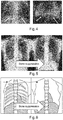
- Fig. 4 shows an X-ray attenuation image on the left hand side and an associated dark field X-ray image on the right hand side for a mouse.
- the impact of the bones (ribs) in the dark-field image from mice is not great, because the bones are small, with the ribs only being visible below the diaphragm. However, for larger patients such as for humans the impact of the bones cannot be ignored.
- an X-ray energy of about 125KV is used as the ribs have less contrast for high KV.
- dark-field imaging is more sensitive at lower x-ray energies, with X-ray energies of about 75 KV being used.
- the ribs become visible at these lower X-ray energies, to the extent that the bones interfere with the ability to analyze and interpret the dark-field image at these energies.
- the ribs also become more visible at these energies in the regular attenuation X-ray image.
- Fig. 5 Shows a regular X-ray attenuation image on the left-hand side, and on the right-hand side shows the X-ray attenuation image with bone suppression having been applied, for example through a technique as described in WO2011/077334A1 .
- Fig. 6 shows in schematic form the imagery shown in Fig. 6 .
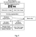
- Fig. 7 shows a workflow for feature suppression in dark field or phase contrast X-ray imaging.
- An attenuation X-ray image of the chest is acquired, and an associated X-ray dark field (and/or phase contrast) image is acquired.
- the attenuation image and the dark-field image acquisition is described in more detail with respect to Figs. 14 and 15 , where it is to be noted and the attenuation image can be acquired at the same time or at different times to the dark field and/or phase contrast image.
- Lung segmentation is carried out for both the attenuation image and the dark-field image, using segmentation techniques as known in the art.
- This segmentation delineates the lungs in both images, and can also be used to register the attenuation image to the dark-field image, such that a region in the attenuation image can be mapped to the same region in the dark-field image.
- the bones in the x-ray attenuation image are clearly visible, as seen in the left hand image of Fig. 8 and its associated schematic representation in the left-hand diagram of Fig. 9 .
- Segmentation of the bones in the X-ray attenuation image is then carried out.
- a bone map is then created, which is in effect that shown in the right image of Fig. 8 and its associated schematic representation in the right-hand diagram of Fig. 9 .
- Bone suppression can then be carried out for the X-ray attenuation image as described for example in WO2011/077334A1 .
- the bones are removed in the image through a virtual replacement of the bones in the body by soft tissue, or by ⁇ Bones > ⁇ S ⁇ ft, where ⁇ relates to X-ray attenuation.
- the locations of the bones in the dark-field image can be determined on the basis of the bone map determined from the attenuation image, and this can be done even though the bones in the dark-field image of themselves not represented in that image with enough contrast of signal-to-noise to be delineated on the basis of just the dark-field image.
- Fig. 10 shows on the left hand side an X-ray attenuation image showing bones, and on the right hand side the X-ray attenuation image having had bones suppressed as described above, with Fig. 11 showing a schematic representation of the images of Fig. 10 .
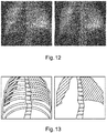
- Fig. 12 shows on the left hand side an original dark field X-ray image showing bones, and on the right hand side the dark field X-ray image with bones having been suppressed as described above, with Fig. 13 showing a schematic representation of the images of Fig. 12 .
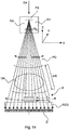
- Fig. 14 shows an apparatus for acquiring the X-ray dark field and/or phase contrast images and that can also acquire X-ray attenuation images.
- the apparatus is capable of imaging for the spatial distribution of absorption of, or in, an object OB and also capable of imaging for the spatial distribution of refraction (phase contrast imaging) and also capable of imaging for the spatial distribution of small angle scattering (dark field imaging).
- the apparatus has a grating based interferometer IF that can be scanned across a stationary X-ray detector D.
- the interferometer IF comprises two grating structures G1 and G2 although, although in other examples a single grating interferometer (having only a single grating G1) is used.
- the X-ray detector D has a pitch sufficiently small, hence a spatial resolution sufficiently large, for detecting i.e. adequately resolving the interference pattern generated by the grating G1 for the purpose of differential phase contrast imaging and/or dark field imaging.
- the X-ray detector may be a high resolution X-ray detector, having for example a spatial resolution of 50 micrometers or more.
- the grating G1 is either an absorption grating or phase shift grating whereas G2 is an absorption gating.
- the gratings are manufactured by photo lithographically processing suitable substrates such as a silicon wafer.
- a pattern of periodic rulings is formed in those silicon "cards" formed by trenches of different aspect ratio.
- the ruling patterns may be one dimensional but may also be two dimensional such as to confer a checker board pattern.
- the X-ray imaging apparatus further comprises an X-ray source XR and the X-ray detector D.
- the X-ray detector D can be a 2D full view X-ray detector, which is either planar or curved.
- a plurality of detector pixels are arranged in rows and columns as an array to form a 2D X-ray radiation sensitive surface capable of registering X-ray radiation emitted by the X-ray source.
- the X-ray detector D and the X-ray source are spaced apart to form an examination region ER.
- the examination region is suitably spaced to receive the object OB to be imaged.
- the object may be inanimate or animate.
- the object may be a piece of luggage or other sample to be imaged, or in a medical context the object may be a human or animal patient or at least an anatomic part of a human or animal.
- the interferometric grating structures G1 and G2 are arranged in the examination region ER between the X-ray source XR and X-ray detector D.
- the X-ray source XR has a focal spot FS from which the X-ray radiation beam emerges. It is the space between the focal spot FS and the X-ray detector's radiation sensitive surface where the two or three grating structures are arranged.
- the grating G1 is a phase grating and the grating G2 is an analyzer grating.
- a further grating G0 which is the source grating.
- the source grating G0 is arranged in proximity of the X-ray source, for example at the exit window of a housing of the X-ray tube.
- the function of the source grating G0 is to make the emitted radiation at least partly coherent.
- the source grating G0 can be dispensed with if an X-ray source is used which is capable of producing coherent radiation.
- the at least partly coherent radiation passes through the examination region ER and interacts with the object OB.
- the object then modulates the attenuation, refraction, and small angle scattering information onto the radiation which can then be extracted by operation of the grating tandem Gland G2.
- the gratings G1, G2 induce an interference pattern which can be detected at the X-ray detector D as fringes of a Moiré pattern. If there was no object in the examination region, there would still be an interference patter observable at the X-ray detector D, called the reference pattern which is normally captured during a calibration procedure.
- the Moiré pattern which is now more appropriately called the object pattern, can be understood as a disturbed version of the reference pattern.
- This difference from the reference pattern can then be used to compute one or all of the three images (attenuation, phase contrast, dark field). This means that the attenuation image is acquired at the same time as the dark field and/or phase contrast image and as such the patient will be in the same state (e.g.
- a scanning motion is performed by the grating tandem G1-G2.
- a series of intensity values are detected at each pixel of the X-ray detector D .
- the detuning of the gratings G1, G2 is such that a period of the Moiré pattern should extend for a few of its cycles (two or three) in the direction of the scan motion.
- the series of intensity values can then be fitted to a (sinusoidal) signal forward model, for example, in order to derive the respective contributions of refraction, absorption, and small angle scatter.
- This type of signal processing is done in a signal processing unit not shown in Figure 14 , but which is known to the skilled person.
- the X-ray detector D remains stationary for any given orientation of the optical axis OX which is shown in Figure 3 to extend along the Z axis. In other words, the X-ray detector D is kept stationary (at least during an image acquisition operation) with respect to an arbitrary reference point in the examination region.
- the interferometric setup as described above is what is commonly referred to as a Talbot-Lau interferometer.
- the distances between G0 and G1 and between G1 and G2 must be finely tuned to fit the requirements of Talbot distance which in turn is a function of the "pitch" (that is, the spatial period of the grating rulings) of the respective grating.
- the "pitch" that is, the spatial period of the grating rulings
- Moving the interferometer IF relative to the X-ray detector D may cause a slight change in fringe distribution due to fringe drift.
- the fringe drift can be compensated by relating such drift to the fringe drift as obtained with a reference scan.
- Such reference scan may be a blank scan performed at the installation of the X-ray imaging apparatus.
- the interferometer IF can be essentially a "grating pack" with the two gratings G1 and G2 fixedly mounted with respect to each other in a suitable frame or cage and this frame is fixedly arranged in a scan arm GT or other moveable gantry structure (not shown in Figure 14 ).
- the arm, and with it the interferometer IF performs a pendulum like motion across the X-ray detector surface.
- the pivot point for the scan arm motion runs through the focal spot FS of the X-ray source but does not need to.
- the gratings G1 and G2 of the interferometer IF are held in fixed spatial relationship with respect to each other at all times during the scan motion and remain essentially parallel, or at least in a fixed spatial relationship, to G0.
- Suitable tracking circuitry (not shown) correlates interferometer position with X-ray detector pixel position to timely trigger a sequence of read-out burst to make sure each pixel is supplied with the above mentioned series of measurements to correctly sample the interference pattern.
- the X-Y plane is the X-ray detector plane with X,Y designating the direction of pixelation in the X-ray detector D.
- the X-ray source rotates around the focal point that passes through the focal spot FS.
- the rotation axis RA for the scan arm GT and X-ray source XR extends into the paper plane of Fig. 14 (along the Y direction). Having the X-ray source rotate in concert with the pendulum motion of the grating tandem G1, G2 allows increasing flux.
- a pre-collimator is arranged between the X-ray source and the object OB so as to conform the radiation beam to the dimensions or footprint of the gratings G1 and/or G2.
- the collimator PC moves in concert with the pendulum motion of the interferometer IF during the image acquisition.
- One way to achieve this is to mount the collimator to the scan arm GT proximate to the source grating G0 at an appropriate distance.
- the source grating G0 also moves in concert with the swinging scanning motion of the grating pack G1, G2.
- An anti-scatter grid ASG may be arranged between the interferometer and the X-ray detector surface.
- the object e.g. a patient
- OB lies on an examination table or couch (not shown in Fig. 14 ) during the image acquisition.
- the patient's longitudinal axis extends into the drawing plane as per Fig. 14 whilst the pendulum motion of the gratings G1, G2 (and that of G0) swings in a vertical plane with the patient's longitudinal axis (in Fig. 14 extending into the Y direction) extending into the paper plane of Fig. 14 .
- the mutually rigidly mounted gratings G1, G2 move the full length from one X-ray detector edge to the opposing X-ray detector edge if a full field image is desired, i.e. an image that is as wide in scan direction as the X-ray detector itself. If the user requests a smaller FOV (field of view), however, a reduced scan range can be used to minimize the acquisition time.
- FOV field of view
- Fig. 15 shows a different example configured to allow the patient to stand (upright) during the X-ray imaging acquisition. This construction may be beneficial for chest imaging. Views A, B represent side elevations of the arrangement whilst view C is a frontal view through the X-ray detector D towards the X-ray source XR, that is, along the optical axis OX. Compared to Fig. 14 the optical axis in the Fig. 15 example is effectively rotated by 90 degrees. In other words the interferometer IF now performs a curved scan motion in a vertical direction (relative to the ground of the examination room) from top to bottom or from bottom to top.
- the gratings G1, G2 of the interferometer IF are now essentially arranged as strip gratings that are co-extensive of the width of the X-ray detector perpendicular to the scanning motion.
- gratings G1, G2 may be formed monolithically from single long wafer or substrate.
- the strip arrangement can be achieved by tiling, that is joining together a plurality of smaller individual monolithic grating modules.
- the X-ray detector may be suspended in a fixture from the ceiling of the examination room or may be mounted on a floor mounted stand.
- the gratings G1 and G2 are rigidly mounted to a scan arm GT.
- the scan arm GT may be floor or ceiling mounted.
- the side views A) and B) show different instances during the scanning motion of the scan arm GT as it is moving along the vertical scan path in a circular or at least arcuate motion.
- the source grating G1 is arranged to rotate in concert about the focal spot FS.
- One way to do this is to have all three gratings arranged in the scan arm to maintain a fixed and parallel relationship during the vertical up or down motion.
- Fig. 15 parts that move simultaneously or in concert are shown in the dashed box representing the scan arm GT.
- the system can easily be operated in the conventional radiography mode, by simply moving the scan arm with the gratings out of the beam. If necessary, a standard chest X-ray image can be acquired immediately before the scan can be exploited by simply swinging the scan arm out of position.
- a computer program or computer program element is provided that is characterized by being configured to execute the method steps of the method according to one of the preceding embodiments, on an appropriate system.
- the computer program element might therefore be stored on a computer unit, which might also be part of an embodiment.
- This computing unit may be configured to perform or induce performing of the steps of the method described above. Moreover, it may be configured to operate the components of the above described apparatus.
- the computing unit can be configured to operate automatically and/or to execute the orders of a user.
- a computer program may be loaded into a working memory of a data processor.
- the data processor may thus be equipped to carry out the method according to one of the preceding embodiments.
- This exemplary embodiment of the invention covers both, a computer program that right from the beginning uses the invention and computer program that by means of an update turns an existing program into a program that uses the invention.
- the computer program element might be able to provide all necessary steps to fulfill the procedure of an exemplary embodiment of the method as described above.
- a computer readable medium such as a CD-ROM
- the computer readable medium has a computer program element stored on it which computer program element is described by the preceding section.
- a computer program may be stored and/or distributed on a suitable medium, such as an optical storage medium or a solid state medium supplied together with or as part of other hardware, but may also be distributed in other forms, such as via the internet or other wired or wireless telecommunication systems.
- a suitable medium such as an optical storage medium or a solid state medium supplied together with or as part of other hardware, but may also be distributed in other forms, such as via the internet or other wired or wireless telecommunication systems.
- the computer program may also be presented over a network like the World Wide Web and can be downloaded into the working memory of a data processor from such a network.
- a medium for making a computer program element available for downloading is provided, which computer program element is arranged to perform a method according to one of the previously described embodiments of the invention.
Landscapes
- Engineering & Computer Science (AREA)
- Health & Medical Sciences (AREA)
- Life Sciences & Earth Sciences (AREA)
- Medical Informatics (AREA)
- Physics & Mathematics (AREA)
- Biomedical Technology (AREA)
- Animal Behavior & Ethology (AREA)
- Biophysics (AREA)
- Nuclear Medicine, Radiotherapy & Molecular Imaging (AREA)
- Optics & Photonics (AREA)
- Pathology (AREA)
- Radiology & Medical Imaging (AREA)
- Veterinary Medicine (AREA)
- Heart & Thoracic Surgery (AREA)
- Molecular Biology (AREA)
- Surgery (AREA)
- High Energy & Nuclear Physics (AREA)
- General Health & Medical Sciences (AREA)
- Public Health (AREA)
- General Physics & Mathematics (AREA)
- Theoretical Computer Science (AREA)
- Computer Vision & Pattern Recognition (AREA)
- Dentistry (AREA)
- Oral & Maxillofacial Surgery (AREA)
- Human Computer Interaction (AREA)
- Apparatus For Radiation Diagnosis (AREA)
- Measurement Of Radiation (AREA)
Description
- The present invention relates to an apparatus for feature suppression in dark field or phase contrast X-ray imaging, to a system for feature suppression in dark field or phase contrast X-ray imaging, and to a method for feature suppression in dark field or phase contrast X-ray imaging, as well as to a computer program element and a computer readable medium.
- Differential phase contrast and dark-field imaging are promising technologies that will likely add additional diagnostic value in particular in the area of chest imaging since these techniques are highly sensitive to changes of the micro-structure of lung tissue. In pre-clinical studies, it has been demonstrated that wide-spread lung diseases like chronic obstructive pulmonary disease (COPD) and fibrosis can be accurately identified and even quantified by this technology in mice. Still it remains open, how to build an operational system, such as a clinical system. However, features such as bones interfere with the imagery, which is exacerbated for larger subjects. Although features such as bones interfere with imagery, they are not depicted with sufficient contrast and signal to noise to enable their removal through image processing techniques.
-
WO2011/077334A1 andUS 2014/140603 relate to bone suppression in X-ray radiograms.US 2015/150529 teaches transferring bone locations from standard X-ray to a phase contrast image for bone-related measurements. - Therefore, it would be advantageous to have an improved technology for providing dark field or phase contrast images.
- The object of the present invention is solved with the subject matter of the independent claims, wherein further embodiments are incorporated in the dependent claims.
- Roughly speaking, according to a first aspect, there is provided an apparatus for feature suppression in dark field or phase contrast X-ray imaging, comprising:
- an input unit;
- a processing unit; and
- an output unit.
- The input unit is configured to provide the processing unit with an X-ray attenuation image of a region of interest of an object. The input unit is also configured to provide the processing unit with a dark field or phase contrast X-ray image of the region of interest of the object. The processing unit is configured to identify a first feature in the X-ray attenuation image. The first feature is an obscuring anatomical feature depicted in the X-ray attenuation image with higher contrast than in the dark field or phase contrast X-ray image. The processing unit is configured to identify a second anatomical feature in the X-ray attenuation image and to identify the second anatomical feature in the dark field or phase contrast X-ray image. The processing unit is further configured to register the dark field or phase contrast X-ray image to the X-ray attenuation image based on the identified second anatomical feature. The processing unit is also configured to determine a location of the first feature in the X-ray attenuation image. The processing unit is also configured to locate the first feature in the dark field or phase contrast X-ray image comprising utilization of information relating to the first feature identified in the X-ray attenuation image by transferring the determined location to the dark field or phase contrast X-ray image. The processing unit is also configured to suppress the first feature in the dark field or phase contrast X-ray image to generate a feature suppressed dark field or phase contrast X-ray image. The output unit is configured to output data representative of the feature suppressed dark field or phase contrast X-ray image.
- In this manner, obscuring features can be removed from dark field or phase contrast images, which could not be removed from those images on the basis of those images alone. This is because in dark field or phase contrast images, obscuring features (such as bone) typically have less contrast and less signal to noise than in regular attenuation images, and cannot be suppressed directly to the required levels of fidelity. Therefore, the obscuring feature is identified in a regular attenuation X-ray image and this information is used to locate the obscuring feature (e.g., bone or bones such as one or more ribs) in the phase contrast or dark field image. Once the location of the obscuring features is known, standard algorithms, in a similar manner as carried out for attenuation images, can be applied to suppress the obscuring features in the dark field or phase contrast image.
- In other words, for the example of a dark field or phase contrast image of a chest, the ribs can be removed from the image to result in an image the diffusion (or attenuation) coefficients of which only depend on the lung.
- In other words, dark field and/or phase contrast imaging can be used to view structures that have similar absorption cross-sections, that would not be discernible using conventional absorption X-ray imaging, but in such dark field and/or phase contrast imaging the obscuring effects of features such as (for example) rib cage bones can be difficult to overcome. Therefore, the dark field and/or phase contrast image is associated with a conventional absorption X-ray of the same object, and in the absorption image the contrast between highly absorbing features such as bone and the adjacent relatively weakly absorbing material is greater than that for the dark field and/or phase contrast image. Therefore, the obscuring feature is identified in the attenuation "conventional" image, and this enables the same feature to be identified and located in the dark field and/or phase contrast image. Having identified the location of the obscuring feature in the dark field and/or phase contrast image, using information from the attenuation image, the obscuring effect of the feature (e.g. rib cage bones) can be mitigated using state of the art techniques, for example in effect changing the properties of the bone to that of the surrounding body material.
- In this way, bone suppression algorithms can be applied to an attenuation image, and the resulting bone map (for the example of a body) that would be used for bone removal (or suppression) in the attenuation image is used for bone removal (suppression) in the dark field or phase contrast image.
- In other words, the processing unit registers the dark field or phase contrast X-ray image to the X-ray attenuation image, and having registered the images and having identified the obscuring feature in the attenuation image, this information can be used to locate the first feature in the dark field or phase contrast X-ray image.
- By registering the phase contrast or dark field image with the attenuation image, the obscuring feature identified in the attenuation image can be more easily located in the phase contrast or dark field image.
- In other words, the first feature is located in the attenuation image and that location is transferred to the dark field or phase contrast X-ray image, thereby locating the obscuring feature in the dark field or phase contrast X-ray image.
- In an example, the processing unit is configured to locate the first feature in the dark field or phase contrast X-ray image comprising utilization of information relating to the second feature identified in the attenuation image and identified in the dark field or phase contrast image.
- In other words, a feature that is discernible in both the attenuation image and in the dark field or phase contrast image can be identified in both images, and because the obscuring feature has been identified in the attenuation image, information regarding the identified feature in both the attenuation and phase contrast/dark field image can be used to locate the obscuring feature in the dark field/phase contrast image.
- In this manner, the obscuring feature can be more easily located in the phase contrast or dark field image.
- In other words, a feature such as a lung is identified in the X-ray attenuation image, and the lung in also shown in a visible and distinct manner in the Dark Field or Phase Contrast image. A correlation between the visible lungs in both images can be made to locate the bones in the DF or PC image, that are not particularly visible, from the positions of the bones that are visible in the X-ray attenuation image.
- According to an example, the processing unit is configured to determine information relating to a relative position of the first feature to the second feature in the X-ray attenuation image, and the processing unit is configured to determine a relative position of the first feature to the second feature in the dark field or phase contrast X-ray image on the basis of the information relating to the relative position of the first feature to the second feature in the X-ray attenuation image.
- In other words, having identified for example a lung in both an attenuation image and a dark field or phase contrast image, then the relative position of for example a bone with respect to the lung in the attenuation image can be used such that the location of the bone in the dark field or phase contrast image is that where the bone has the same relative position with respect to the lung in the dark field or phase contrast image as it has in the attenuation image.
- According to an example, the object is a body part and the second feature comprises one or more of, at least a part of a lung, at least a part of a diaphragm, and at least a part of a spine.
- According to an example, the first feature comprises at least a part of a bone structure.
- In this manner, the obscuring effects of bone in a dark field or phase contrast image of a body can be mitigated.
- According to an example, the processing unit is configured to determine a product of a diffusion coefficient (or attenuation coefficient) and a distance for the first feature in the dark field or phase contrast X-ray image to suppress the first feature in the dark field or phase contrast X-ray image.
- In other words, the X-ray attenuation is the product of an attenuation per unit length multiplied by a length. Thus, the attenuation provided by a feature such as a bone is the attenuation per unit length for a bone multiplied by the length the X-ray passes through the bone. Thus, having identified the first feature (such as a bone) the thickness of the bone through which an X-ray passes can be estimated. Then, the diffusion (or attenuation) coefficient for soft material surrounding the bone can be multiplied with the length through the bone to provide an effective attenuation for the bone, had it actually been comprised of such soft material. This information can be used to suppress the bone (first feature) in the dark field or phase contrast image.
- In this manner, the obscuring feature can be made to appear like the material surrounding it. For example, for a rib bone surrounded by body flesh, the product of diffusion coefficient and length at the position of the rib bone can be replaced by that for the diffusion coefficient and length for the surrounding flesh. The rib bone will then appear to be the made from "flesh" rather than bone, and its obscuring effect will be mitigated.
- According to an example, the processing unit is configured to determine a diffusion coefficient for the first feature and determine a distance comprising a length through the first feature in the dark field or phase contrast X-ray image. The processing unit is also configured to determine a diffusion coefficient for a feature other than the first feature in the dark field or phase contrast X-ray image. The processing unit is configured to replace the product of the diffusion coefficient for the first feature and the distance for the first feature with the product of the diffusion coefficient for the second feature and the distance for the first feature to suppress the first feature in the dark field or phase contrast X-ray image.
- In this manner, for the example of a body, the suppression of the first feature can be considered as a virtual replacement of the bones in the body by soft tissue. In the dark field or phase contrast image, the bones will be made to disappear.
- According to an example, the X-ray attenuation image and dark field or phase contrast X-ray image were acquired at substantially the same time.
- In other words, the transmitted beam that passes through an object that is interrogated to produce a phase contrast or dark field image, can at the same time be used to produce an attenuation image.
- In this manner, there is a direct correspondence between the attenuation image and dark field or phase contrast image, and having identified the obscuring feature in the attenuation image it can be easily located in the dark field or phase contrast image.
- In a second aspect, there is provided a system for feature suppression in dark field or phase contrast X-ray imaging, the system comprising:
- at least one image acquisition unit; and
- an apparatus for feature suppression in dark field or phase contrast X-ray imaging according to one of the above examples of an apparatus according to the first aspect. The at least one image acquisition unit is configured to provide the X-ray attenuation image, and to provide the dark field or phase contrast X-ray image. The output unit is configured to output the feature suppressed dark field or phase contrast X-ray image.
- In a third aspect, there is provided a method for feature suppression in dark field or phase contrast X-ray imaging, comprising:
- a) providing an X-ray attenuation image of a region of interest of an object;
- b) providing a dark field or phase contrast X-ray image of the region of interest of the object;
- c) identifying a first feature in the X-ray attenuation image;
- d1) identifying a second anatomical feature in the X-ray attenuation image;
- d2) identifying the second anatomical feature in the dark field or phase contrast X-ray image;
- e) registering the dark field or phase contrast X-ray image to the X-ray attenuation image based on the identified second anatomical feature;
- f) determining a location of the first feature in the X-ray attenuation image
- g) locating the first feature in the dark field or phase contrast X-ray image comprising utilizing information relating to the first feature identified in the X-ray attenuation image by transferring the determined location to the dark field or phase contrast X-ray image;
- h) suppressing the first feature in the dark field or phase contrast X-ray image to generate a feature suppressed dark field or phase contrast X-ray image; and
- i) outputting data representative of the feature suppressed dark field or phase contrast X-ray image.
- In an example, the first feature is a highly absorbing anatomical feature, for example bones.
- In an example, the first feature is an anatomical feature, for example an obscuring feature, such as bones.
- In an example, the first feature is depicted with higher contrast in the X-ray attenuation image than in the dark field or phase contrast X-ray image.
- According to another aspect, there is provided a computer program element controlling apparatus as previously described which, in the computer program element is executed by processing unit, is adapted to perform the method steps as previously described.
- According to another aspect, there is provided a computer readable medium having stored computer element as previously described.
- Advantageously, the benefits provided by any of the above aspects and examples equally apply to all of the other aspects and examples and vice versa.
- The above aspects and examples will become apparent from and be elucidated with reference to the embodiments described hereinafter.
- Exemplary embodiments will be described in the following with reference to the following drawings:
-
Fig. 1 shows an example of an apparatus for feature suppression in dark field or phase contrast X-ray imaging; -
Fig. 2 shows an example of a system for feature suppression in dark field or phase contrast X-ray imaging; -
Fig. 3 shows an example of a method for feature suppression in dark field or phase contrast X-ray imaging; -
Fig. 4 shows on the left hand side an attenuation X-ray image and on the right hand side a dark field X-ray image for a mouse; -
Fig. 5 shows an example of bone suppression in an X-ray image for a human, withFig. 6 showing a schematic representation ofFig. 5 ; -
Fig. 7 shows a schematic representation of workflow for feature suppression in dark field or phase contrast X-ray imaging; -
Fig. 8 shows on the left hand side an unprocessed attenuation X-ray image for a human, and on the right hand side the bones from this image, withFig. 9 showing a schematic representation ofFig. 8 ; -
Fig. 10 shows on the left hand side an attenuation X-ray image for a human, and on the right hand side the attenuation image without bones, withFig. 11 showing a schematic representation ofFig. 10 ; -
Fig. 12 shows on the left hand side an original dark field X-ray image for a human, and on the right hand side the dark field image with bones suppressed, withFig. 13 showing a schematic representation ofFig. 12 ; -
Figs. 14-15 show schematic set ups of examples of a system for feature suppression in dark field or phase contrast X-ray imaging. -
Fig. 1 shows anapparatus 10 for feature suppression in dark field or phase contrast X-ray imaging. Theapparatus 10 comprises aninput unit 20, aprocessing unit 30, and anoutput unit 40. Theinput unit 20 is configured to provide theprocessing unit 30 with an X-ray attenuation image of a region of interest of an object. Theinput unit 20 is also configured to provide theprocessing unit 30 with a dark field or phase contrast X-ray image of the region of interest of the object. Theprocessing unit 30 is configured to identify a first feature in the X-ray attenuation image. The first feature is an obscuring anatomical feature depicted in the X-ray attenuation image with higher contrast than in the dark field or phase contrast X-ray image. Theprocessing unit 30 is also configured to identify a second anatomical feature in the X-ray attenuation image; and to identify the second anatomical feature in the dark field or phase contrast X-ray image. The processing unit is further configured to register the dark field or phase contrast X-ray image to the X-ray attenuation image based on the identified second anatomical feature. Theprocessing unit 30 is also configured to determine a location of the first feature in the X-ray attenuation image; and to locate the first feature in the dark field or phase contrast X-ray image comprising utilization of information relating to the first feature identified in the X-ray attenuation image by transferring the determined location to the dark field or phase contrast X-ray image. Theprocessing unit 30 is also configured to suppress the first feature in the dark field or phase contrast X-ray image to generate a feature suppressed dark field or phase contrast X-ray image. Theoutput unit 40 is configured to output data representative of the feature suppressed dark field or phase contrast X-ray image. - In an example, the X-ray attenuation image is a radiography image.
- In an example, the X-ray attenuation image is an angiographic image.
- In an example, identifying the first feature in the attenuation X-ray image means to identify the location of the first feature. In other words, a location of the first feature in the attenuation X-ray image is identified.
- In an example, identifying the first feature in the attenuation X-ray image comprises application of a segmentation procedure.
- In an example, locating the first feature in the dark field or phase contrast image comprises application of a segmentation procedure.
- In an example, the first feature in the attenuation X-ray image is presented in a visible and distinct manner. The term "visible and distinct" relates to the first feature being presented such that at least a part of that first feature can be located and/or identified and/or delineated, either manually or automatically.
- The
processing unit 30 is configured to register the dark field or phase contrast X-ray image to the X-ray attenuation image. - In an example, registering accounts for the patient's cardiac cycle and/or breathing cycle.
- In an example, registering may comprise the step of warping the region of interest of the attenuation image and/or the region of interest of the dark filed or phase contrast image.
- In an example, acquisition of the attenuation image is performed at the same angulation as that used for acquisition of the dark image or phase contrast image. For example, both acquisitions are performed with the same C-arm angulation. This provides for ease of aligning the images.
- In an example, the aligning leads to a spatial matching of the region of interest of the attenuation image with the region of interest of the dark field or phase contrast image.
- In an example, registering the dark field or phase contrast image to the attenuation X-ray image comprises application of a segmentation procedure.
- According to an example, the
processing unit 30 is configured to determine a location of the first feature in the X-ray attenuation image and transfer that location to the dark field or phase contrast X-ray image. - In an example, locating the first feature in the attenuation X-ray image comprises application of a segmentation procedure.
- According to an example, the
processing unit 30 is configured to identify a second feature in the X-ray attenuation image. The processing unit is also configured to identify the second feature in the dark field or phase contrast X-ray image, and the processing unit is configured to locate the first feature in the dark field or phase contrast X-ray image comprising utilization of information relating to the second feature identified in the attenuation image and identified in the dark field or phase contrast image. - In an example, identifying the second feature in the attenuation X-ray image means to identify the location of the second feature. In other words, a location of the second feature in the attenuation X-ray image is identified. In an example, identifying the second feature in the dark field or phase contrast image means to identify the location of the second feature. In other words, a location of the second feature in the dark field or phase contrast image is identified. To put this another way, in an example, the processing unit is configured to locate the second feature in the X-ray attenuation image; and the processing unit is configured to locate the second feature in the dark field or phase contrast X-ray image.
- In an example, the identified second feature in both the attenuation and phase contrast or dark field image is made use of in registering the phase contrast or dark field image to the attenuation image.
- In an example, identifying the second feature in the attenuation X-ray image comprises application of a segmentation procedure. In an example, identifying the second feature in the dark field or phase contrast image comprises application of a segmentation procedure.
- In an example, the second feature in the attenuation X-ray image is presented in a visible and distinct manner and the second feature in the Dark field or Phase Contrast image is presented in a visible and distinct manner. The term "visible and distinct" relates to the second feature being presented such that at least a part of that second feature can be located and/or identified and/or delineated, either manually or automatically.
- According to an example, the
processing unit 30 is configured to determine information relating to a relative position of the first feature to the second feature in the X-ray attenuation image. The processing unit is also configured to determine a relative position of the first feature to the second feature in the dark field or phase contrast X-ray image on the basis of the information relating to the relative position of the first feature to the second feature in the X-ray attenuation image. - According to an example, the object is a body part and the second feature comprises one or more of, at least a part of a lung, at least a part of a diaphragm, and at least a part of a spine.
- According to an example, the first feature comprises at least a part of a bone structure.
- According to an example, the
processing unit 30 is configured to determine a product of a diffusion coefficient and a distance for the first feature in the dark field or phase contrast X-ray image to suppress the first feature in the dark field or phase contrast X-ray image. - According to an example, the
processing unit 30 is configured to determine a diffusion coefficient for the first feature and determine a distance comprising a length through the first feature in the dark field or phase contrast X-ray image. The processing unit is also configured to determine a diffusion coefficient for a feature other than the first feature in the dark field or phase contrast X-ray image. The processing unit is further configured to replace the product of the diffusion coefficient for the first feature and the distance for the first feature with the product of the diffusion coefficient for the second feature and the distance for the first feature to suppress the first feature in the dark field or phase contrast X-ray image. - According to an example, the X-ray attenuation image and dark field or phase contrast X-ray image were acquired at substantially the same time.
-
Fig. 2 shows asystem 100 for feature suppression in dark field or phase contrast X-ray imaging. Thesystem 100 comprises at least oneimage acquisition unit 110, and anapparatus 10 for feature suppression in dark field or phase contrast X-ray imaging as described with respect toFig. 1 . The at least oneimage acquisition unit 110 is configured to provide the X-ray attenuation image, and to provide the dark field or phase contrast X-ray image. Theoutput unit 40 is configured to output the feature suppressed dark field or phase contrast X-ray image. - In an example, the at least one image acquisition unit comprises a grating based differential phase contrast and dark field X-ray imaging device. In an example, the at least one image acquisition unit comprises an interferometer arrangement.
- In an example, the at least one image acquisition unit comprises an X-ray imaging device. For example, the device can be a tomography arrangement, or a CT arrangement.
- In an example, the at least one image acquisition unit can operate in a standard radiography mode, with transmitted intensities of radiation providing information on attenuation through the object. In an example, the at least one image acquisition unit can operate in a Differential phase contrast imaging (DPCI) mode. In an example, the same image acquisition unit can be used to acquire the attenuation and dark field or phase contrast images. For example, an interferometer arrangement of a DPCI apparatus can be swung out of the X-ray beam and a normal radiography, attenuation, image acquired. Then, the interferometer arrangement can be swung back into the X-ray beam and the dark field X-ray or phase contrast image acquired.
- In an example, the at least one image acquisition unit comprises is a differential phase contrast imaging (DPCI) apparatus. In an example, the at least one image acquisition unit generates an attenuation image, relating to the detection of intensity (intensity) values of X-rays with and without the object in the examination region. In an example, the at least one image acquisition unit generates a phase contrast (or differential phase) image, relating to the detection of the phases of the X-rays with and without the object in the examination region. In an example, the at least one image acquisition unit generates a dark field (or de-coherence) image, relating to the detection of fringe visibilities of the X-rays with and without the object in the examination region. In an example, the at least one image acquisition unit generates any combination of these images. For example, the at least one image acquisition unit can generate an attenuation image, and generate a phase contrast image, and generate a dark field image. In an example, an attenuation image, a phase contrast image, and a dark field image can be generated at the same time.
- In an example, the interferometer arrangement comprises a Talbot interferometer. In an example, the interferometer arrangement comprises a diffraction grating configured to modulate onto the X-rays emitted by the source an interference pattern detectable by the X-ray detector as X-ray fringes. In an example, the interferometer arrangement comprises a second diffraction grating configured to analyze the interference pattern. In an example, the second diffraction grating is an absorption grating. In an example, the two gratings are arranged on mutually opposite sides of an examination region. In an example, the two gratings are arranged on the same side of an examination region. In an example, the interferometer comprises a source grating in addition to the one or two gratings already discussed. In this example, the source grating is located relatively close to the X-ray source and serves to make the X-rays propagating after the source grating partly coherent. In other words, an X-ray source can be adapted so as to emit radiation that is more coherent than if the source grating was not present. Therefore, in some examples a source grating is not required, for example when the X-ray source already produces suitably coherent X-rays. In an example, the interferometer arrangement is configured to produce Moiré fringes. In an example, the interferometer arrangement is purposely detuned such that some fringes are present in a detector area. In an example, the interferometer arrangement is purposely detuned by having a first grating inclined at a small angle to a second grating. In an example, detuning leads to the generation of Moiré fringes on the detector.
- In one example, the interferometer arrangement comprises two gratings which are fixedly mounted with respect to each other in a suitable frame or cage and this frame is fixedly arranged in a scan arm or other moveable gantry structure. In other words, the interferometer arrangement can be swung in and out of the X-ray beam such that the apparatus can be operated in both a DPCI mode and in a conventional radiography mode. In the DPCI mode, the arm can be translated or rotated, such that at least part of the object is scanned.
- In an example, the output unit outputs an absorption (or attenuation) image. In an example, the output unit outputs a phase contrast (or differential phase) image. In an example, the output unit outputs a dark field image. In an example, the output unit outputs any combination of attenuation, phase contrast and dark field images. In other words, the output unit can simultaneously output all three types of image. In an example, the output unit outputs data representative of the object on a monitor such as a visual display unit or on a number of separate monitors. For example, attenuation, phase contrast and dark field images can be presented on a single monitor or presented on separate monitors.
- In an example, the system has useful application in a clinical environment such as a hospital. In an example, the system can be used for mammography, diagnostic radiology and interventional radiology for the medical examination of patients. In an example, the system has useful application in an industrial environment, for example in nondestructive testing (e.g. analysis as to composition, structure and/or qualities of biological as well non-biological samples) as well as security scanning (e.g. scanning of luggage in airports). The apparatus has this application applicability too, as well as the method discussed below.
- In an example, the fringe pattern generated at a current scan arm position is used to determine a visibility or mean visibility and at the same time is used to determine a transmission intensity of X-ray radiation at that arm position. In other words, an attenuation image can be acquired at the same time as a phase contrast and/or dark field image.
- In an example, an image acquisition unit, such as a C-arm system, is used to acquire the attenuation image, and a different image acquisition unit, such as a DPCI system, is used to acquire the dark field and/or phase contrast image.
- In an example, the object is a body or body part. In an example, the object is a piece of luggage or a part of a piece of luggage or a piece of luggage and its contents. In an example, the object is a part of an industrial device or machine part. In an example, the first feature is a bone. In an example, the first feature is a part of a piece of luggage such as a frame of a suitcase. In an example, the first feature is an item of apparel within a suitcase such as a sock or other item that is obscuring the contents of the suitcase. In an example, the second feature is a lung, a diaphragm or a part of the spine. In an example, the second feature is a part of the suitcase frame or other part of the luggage that is clearly discernible in both an attenuation image and dark field or phase contrast image (such as for example a shoe or shoes inside a suitcase).
-
Fig. 3 shows a method 200 for feature suppression in dark field or phase contrast X-ray imaging in its basic steps. The method 200 comprises: - in a providing
step 210, also referred to as step a), an X-ray attenuation image of a region of interest of an object is provided; - in a providing
step 220, also referred to as step b), a dark field or phase contrast X-ray image of the region of interest of the object is provided; - in an identifying
step 230, also referred to as step c), a first feature in the X-ray attenuation image is identified; - in another identifying
step 280, also referred to as step d1), a second anatomical feature is identified in the X-ray attenuation image; - in a further identifying
step 290, also referred to as step d2), the second anatomical feature is identified in the dark field or phase contrast X-ray image; - in a registering
step 270, also referred to as step e), the dark field or phase contrast X-ray image is registered to the X-ray attenuation image based on the identified second anatomical feature; - in a determining
step 242, also referred to as step f), a location of the first feature in the X-ray attenuation image is determined; - in a locating
step 240, also referred to as step g), the first feature in the dark field or phase contrast X-ray image is located comprising utilizing information relating to the first feature identified in the X-ray attenuation image by transferring the determined location to the dark field or phase contrast X-ray image; - in a suppressing
step 250, also referred to as step h), the first feature in the dark field or phase contrast X-ray image is suppressed to generate a feature suppressed dark field or phase contrast X-ray image; and - in an outputting
step 260, also referred to as step i), data representative of the feature suppressed dark field or phase contrast X-ray image is output. - In an example, step g) comprises utilizing 244 information relating to the second feature identified in the attenuation image and identified in the dark field or phase contrast image.
- In an example, step g) comprises determining 246 information relating to a relative position of the first feature to the second feature in the X-ray attenuation image, and determining a relative position of the first feature to the second feature in the dark field or phase contrast X-ray image on the basis of the information relating to the relative position of the first feature to the second feature in the X-ray attenuation image.
- In an example, step h) comprises determining 252 a product of a diffusion coefficient and a distance for the first feature in the dark field or phase contrast X-ray image to suppress the first feature in the dark field or phase contrast X-ray image.
- In an example, step h) comprises determining 254 a diffusion coefficient for the first feature and determining a distance comprising a length through the first feature in the dark field or phase contrast X-ray image; and determining 256 a diffusion coefficient for a feature other than the first feature in the dark field or phase contrast X-ray image; and replacing 258 the product of the diffusion coefficient for the first feature and the distance for the first feature with the product of the diffusion coefficient for the second feature and the distance for the first feature to suppress the first feature in the dark field or phase contrast X-ray image.
- The apparatus, system and method for feature suppression in dark field or phase contrast X-ray imaging is now described in further detail with reference to
Figs. 4-15 . -
Fig. 4 shows an X-ray attenuation image on the left hand side and an associated dark field X-ray image on the right hand side for a mouse. The impact of the bones (ribs) in the dark-field image from mice is not great, because the bones are small, with the ribs only being visible below the diaphragm. However, for larger patients such as for humans the impact of the bones cannot be ignored. In regular attenuation images of human patients an X-ray energy of about 125KV is used as the ribs have less contrast for high KV. However, dark-field imaging is more sensitive at lower x-ray energies, with X-ray energies of about 75 KV being used. The ribs become visible at these lower X-ray energies, to the extent that the bones interfere with the ability to analyze and interpret the dark-field image at these energies. The ribs also become more visible at these energies in the regular attenuation X-ray image. -
Fig. 5 Shows a regular X-ray attenuation image on the left-hand side, and on the right-hand side shows the X-ray attenuation image with bone suppression having been applied, for example through a technique as described inWO2011/077334A1 .Fig. 6 shows in schematic form the imagery shown inFig. 6 . -
Fig. 7 shows a workflow for feature suppression in dark field or phase contrast X-ray imaging. An attenuation X-ray image of the chest is acquired, and an associated X-ray dark field (and/or phase contrast) image is acquired. The attenuation image and the dark-field image acquisition is described in more detail with respect toFigs. 14 and15 , where it is to be noted and the attenuation image can be acquired at the same time or at different times to the dark field and/or phase contrast image. Lung segmentation is carried out for both the attenuation image and the dark-field image, using segmentation techniques as known in the art. This segmentation delineates the lungs in both images, and can also be used to register the attenuation image to the dark-field image, such that a region in the attenuation image can be mapped to the same region in the dark-field image. The bones in the x-ray attenuation image are clearly visible, as seen in the left hand image ofFig. 8 and its associated schematic representation in the left-hand diagram ofFig. 9 . Segmentation of the bones in the X-ray attenuation image is then carried out. A bone map is then created, which is in effect that shown in the right image ofFig. 8 and its associated schematic representation in the right-hand diagram ofFig. 9 . Bone suppression can then be carried out for the X-ray attenuation image as described for example inWO2011/077334A1 . In effect the bones are removed in the image through a virtual replacement of the bones in the body by soft tissue, or by µBones > µSοft, where µ relates to X-ray attenuation. Having registered the attenuation image to the dark field image, the locations of the bones in the dark-field image can be determined on the basis of the bone map determined from the attenuation image, and this can be done even though the bones in the dark-field image of themselves not represented in that image with enough contrast of signal-to-noise to be delineated on the basis of just the dark-field image. Having identified the location of the bones in the dark-field image, a similar technique of bone suppression as applied to the X-ray attenuation image is now be applied to the dark-field image. The technique applied to the dark field image then suppresses the bones in the dark field image. In effect:
[-εLungs∗1Lungs -εSoft∗1soft] -
Fig. 10 shows on the left hand side an X-ray attenuation image showing bones, and on the right hand side the X-ray attenuation image having had bones suppressed as described above, withFig. 11 showing a schematic representation of the images ofFig. 10 . -
Fig. 12 shows on the left hand side an original dark field X-ray image showing bones, and on the right hand side the dark field X-ray image with bones having been suppressed as described above, withFig. 13 showing a schematic representation of the images ofFig. 12 . -
Fig. 14 shows an apparatus for acquiring the X-ray dark field and/or phase contrast images and that can also acquire X-ray attenuation images. The apparatus is capable of imaging for the spatial distribution of absorption of, or in, an object OB and also capable of imaging for the spatial distribution of refraction (phase contrast imaging) and also capable of imaging for the spatial distribution of small angle scattering (dark field imaging). The apparatus has a grating based interferometer IF that can be scanned across a stationary X-ray detector D. In this example, the interferometer IF comprises two grating structures G1 and G2 although, although in other examples a single grating interferometer (having only a single grating G1) is used. In the specific case of a single grating interferometer IF, the X-ray detector D has a pitch sufficiently small, hence a spatial resolution sufficiently large, for detecting i.e. adequately resolving the interference pattern generated by the grating G1 for the purpose of differential phase contrast imaging and/or dark field imaging. For that purpose the X-ray detector may be a high resolution X-ray detector, having for example a spatial resolution of 50 micrometers or more. - In
Fig. 14 , the grating G1 is either an absorption grating or phase shift grating whereas G2 is an absorption gating. The gratings are manufactured by photo lithographically processing suitable substrates such as a silicon wafer. A pattern of periodic rulings is formed in those silicon "cards" formed by trenches of different aspect ratio. The ruling patterns may be one dimensional but may also be two dimensional such as to confer a checker board pattern. - The X-ray imaging apparatus further comprises an X-ray source XR and the X-ray detector D. The X-ray detector D can be a 2D full view X-ray detector, which is either planar or curved. A plurality of detector pixels are arranged in rows and columns as an array to form a 2D X-ray radiation sensitive surface capable of registering X-ray radiation emitted by the X-ray source.
- The X-ray detector D and the X-ray source are spaced apart to form an examination region ER. The examination region is suitably spaced to receive the object OB to be imaged. The object may be inanimate or animate. For instance the object may be a piece of luggage or other sample to be imaged, or in a medical context the object may be a human or animal patient or at least an anatomic part of a human or animal.
- The interferometric grating structures G1 and G2 are arranged in the examination region ER between the X-ray source XR and X-ray detector D. The X-ray source XR has a focal spot FS from which the X-ray radiation beam emerges. It is the space between the focal spot FS and the X-ray detector's radiation sensitive surface where the two or three grating structures are arranged. The grating G1 is a phase grating and the grating G2 is an analyzer grating. In some embodiments, there is in addition to the interferometric gratings G1, G2 of the interferometer IF, a further grating G0 which is the source grating.
- The source grating G0 is arranged in proximity of the X-ray source, for example at the exit window of a housing of the X-ray tube. The function of the source grating G0 is to make the emitted radiation at least partly coherent. In other words, the source grating G0 can be dispensed with if an X-ray source is used which is capable of producing coherent radiation.
- In operation the at least partly coherent radiation passes through the examination region ER and interacts with the object OB. The object then modulates the attenuation, refraction, and small angle scattering information onto the radiation which can then be extracted by operation of the grating tandem Gland G2. The gratings G1, G2 induce an interference pattern which can be detected at the X-ray detector D as fringes of a Moiré pattern. If there was no object in the examination region, there would still be an interference patter observable at the X-ray detector D, called the reference pattern which is normally captured during a calibration procedure. This comes about by especially adjusting or "detuning" the mutual spatial relationship between the two gratings G1 and G2 by inducing a slight flexure for instance so that the two gratings are not perfectly parallel. Now, if the object is positioned in the examination region and interacts with the radiation as mentioned, the Moiré pattern, which is now more appropriately called the object pattern, can be understood as a disturbed version of the reference pattern. This difference from the reference pattern can then be used to compute one or all of the three images (attenuation, phase contrast, dark field). This means that the attenuation image is acquired at the same time as the dark field and/or phase contrast image and as such the patient will be in the same state (e.g. breathing or other movement) and image registration is made more simple, enabling the location of the bones in the attenuation image to be transferred to locations in the dark field and/or phase contrast image. To be able to acquire suitable signals from which the images can be computed, a scanning motion is performed by the grating tandem G1-G2. As a result of this motion, at each pixel of the X-ray detector D a series of intensity values are detected. For good results, the detuning of the gratings G1, G2 is such that a period of the Moiré pattern should extend for a few of its cycles (two or three) in the direction of the scan motion. For each X-ray detector pixel, the series of intensity values can then be fitted to a (sinusoidal) signal forward model, for example, in order to derive the respective contributions of refraction, absorption, and small angle scatter. This type of signal processing is done in a signal processing unit not shown in
Figure 14 , but which is known to the skilled person. The X-ray detector D remains stationary for any given orientation of the optical axis OX which is shown inFigure 3 to extend along the Z axis. In other words, the X-ray detector D is kept stationary (at least during an image acquisition operation) with respect to an arbitrary reference point in the examination region. The interferometric setup as described above is what is commonly referred to as a Talbot-Lau interferometer. The distances between G0 and G1 and between G1 and G2 must be finely tuned to fit the requirements of Talbot distance which in turn is a function of the "pitch" (that is, the spatial period of the grating rulings) of the respective grating. Moving the interferometer IF relative to the X-ray detector D may cause a slight change in fringe distribution due to fringe drift. However, the fringe drift can be compensated by relating such drift to the fringe drift as obtained with a reference scan. Such reference scan may be a blank scan performed at the installation of the X-ray imaging apparatus. - The interferometer IF can be essentially a "grating pack" with the two gratings G1 and G2 fixedly mounted with respect to each other in a suitable frame or cage and this frame is fixedly arranged in a scan arm GT or other moveable gantry structure (not shown in
Figure 14 ). The arm, and with it the interferometer IF performs a pendulum like motion across the X-ray detector surface. The pivot point for the scan arm motion runs through the focal spot FS of the X-ray source but does not need to. The gratings G1 and G2 of the interferometer IF are held in fixed spatial relationship with respect to each other at all times during the scan motion and remain essentially parallel, or at least in a fixed spatial relationship, to G0. Suitable tracking circuitry (not shown) correlates interferometer position with X-ray detector pixel position to timely trigger a sequence of read-out burst to make sure each pixel is supplied with the above mentioned series of measurements to correctly sample the interference pattern. - In
Fig. 14 , the X-Y plane is the X-ray detector plane with X,Y designating the direction of pixelation in the X-ray detector D. The X-ray source rotates around the focal point that passes through the focal spot FS. The rotation axis RA for the scan arm GT and X-ray source XR extends into the paper plane ofFig. 14 (along the Y direction). Having the X-ray source rotate in concert with the pendulum motion of the grating tandem G1, G2 allows increasing flux. - In the example of
Fig. 14 , a pre-collimator is arranged between the X-ray source and the object OB so as to conform the radiation beam to the dimensions or footprint of the gratings G1 and/or G2. The collimator PC moves in concert with the pendulum motion of the interferometer IF during the image acquisition. One way to achieve this is to mount the collimator to the scan arm GT proximate to the source grating G0 at an appropriate distance. The source grating G0 also moves in concert with the swinging scanning motion of the grating pack G1, G2. One way to do this is to mount the grating in the scan arm. An anti-scatter grid ASG may be arranged between the interferometer and the X-ray detector surface. - In the example of
Fig. 14 it is envisaged that the object, e.g. a patient, OB lies on an examination table or couch (not shown inFig. 14 ) during the image acquisition. In other words the patient's longitudinal axis extends into the drawing plane as perFig. 14 whilst the pendulum motion of the gratings G1, G2 (and that of G0) swings in a vertical plane with the patient's longitudinal axis (inFig. 14 extending into the Y direction) extending into the paper plane ofFig. 14 . - The mutually rigidly mounted gratings G1, G2 move the full length from one X-ray detector edge to the opposing X-ray detector edge if a full field image is desired, i.e. an image that is as wide in scan direction as the X-ray detector itself. If the user requests a smaller FOV (field of view), however, a reduced scan range can be used to minimize the acquisition time.
-
Fig. 15 shows a different example configured to allow the patient to stand (upright) during the X-ray imaging acquisition. This construction may be beneficial for chest imaging. Views A, B represent side elevations of the arrangement whilst view C is a frontal view through the X-ray detector D towards the X-ray source XR, that is, along the optical axis OX. Compared toFig. 14 the optical axis in theFig. 15 example is effectively rotated by 90 degrees. In other words the interferometer IF now performs a curved scan motion in a vertical direction (relative to the ground of the examination room) from top to bottom or from bottom to top. This is indicated in frontal view C by the arrows showing a (downward) movement of the interferometer IF during operation. Although not necessarily so in all examples, inFig. 15 the gratings G1, G2 of the interferometer IF are now essentially arranged as strip gratings that are co-extensive of the width of the X-ray detector perpendicular to the scanning motion. Again, gratings G1, G2 may be formed monolithically from single long wafer or substrate. However, in other embodiments, the strip arrangement can be achieved by tiling, that is joining together a plurality of smaller individual monolithic grating modules. The X-ray detector may be suspended in a fixture from the ceiling of the examination room or may be mounted on a floor mounted stand. The gratings G1 and G2 are rigidly mounted to a scan arm GT. Equally, the scan arm GT may be floor or ceiling mounted. The side views A) and B) show different instances during the scanning motion of the scan arm GT as it is moving along the vertical scan path in a circular or at least arcuate motion. Again, although not necessarily in all embodiments, the source grating G1 is arranged to rotate in concert about the focal spot FS. One way to do this is to have all three gratings arranged in the scan arm to maintain a fixed and parallel relationship during the vertical up or down motion. InFig. 15 parts that move simultaneously or in concert are shown in the dashed box representing the scan arm GT. The system can easily be operated in the conventional radiography mode, by simply moving the scan arm with the gratings out of the beam. If necessary, a standard chest X-ray image can be acquired immediately before the scan can be exploited by simply swinging the scan arm out of position. - In another exemplary embodiment, a computer program or computer program element is provided that is characterized by being configured to execute the method steps of the method according to one of the preceding embodiments, on an appropriate system.
- The computer program element might therefore be stored on a computer unit, which might also be part of an embodiment. This computing unit may be configured to perform or induce performing of the steps of the method described above. Moreover, it may be configured to operate the components of the above described apparatus. The computing unit can be configured to operate automatically and/or to execute the orders of a user. A computer program may be loaded into a working memory of a data processor. The data processor may thus be equipped to carry out the method according to one of the preceding embodiments.
- This exemplary embodiment of the invention covers both, a computer program that right from the beginning uses the invention and computer program that by means of an update turns an existing program into a program that uses the invention.
- Further on, the computer program element might be able to provide all necessary steps to fulfill the procedure of an exemplary embodiment of the method as described above.
- According to a further exemplary embodiment of the present invention, a computer readable medium, such as a CD-ROM, is presented wherein the computer readable medium has a computer program element stored on it which computer program element is described by the preceding section.
- A computer program may be stored and/or distributed on a suitable medium, such as an optical storage medium or a solid state medium supplied together with or as part of other hardware, but may also be distributed in other forms, such as via the internet or other wired or wireless telecommunication systems.
- However, the computer program may also be presented over a network like the World Wide Web and can be downloaded into the working memory of a data processor from such a network. According to a further exemplary embodiment of the present invention, a medium for making a computer program element available for downloading is provided, which computer program element is arranged to perform a method according to one of the previously described embodiments of the invention.
- While the invention has been illustrated and described in detail in the drawings and foregoing description, such illustration and description are to be considered illustrative or exemplary and not restrictive. The invention is not limited to the disclosed embodiments. Other variations to the disclosed embodiments can be understood and effected by those skilled in the art in practicing a claimed invention, from a study of the drawings, the disclosure, and the dependent claims.
- In the claims, the word "comprising" does not exclude other elements or steps, and the indefinite article "a" or "an" does not exclude a plurality. Any reference signs in the claims should not be construed as limiting the scope.
Claims (12)
- An apparatus (10) adapted to feature suppression in dark field or phase contrast X-ray imaging, comprising:- an input unit (20);- a processing unit (30); and- an output unit (40);wherein the input unit is configured to provide the processing unit with an X-ray attenuation image of a region of interest of an object;
wherein the input unit is configured to provide the processing unit with a dark field or phase contrast X-ray image of the region of interest of the object;
wherein the processing unit is configured to identify a first feature in the X-ray attenuation image; and to identify a second anatomical feature in the X-ray attenuation image; and to identify the second anatomical feature in the dark field or phase contrast X-ray image; wherein the first feature is an obscuring anatomical feature depicted in the X-ray attenuation image with higher contrast than in the dark field or phase contrast X-ray image.;
wherein the processing unit is further configured to register the dark field or phase contrast X-ray image to the X-ray attenuation image based on the identified second anatomical feature;
wherein the processing unit is configured to determine a location of the first feature in the X-ray attenuation image; and to locate the first feature in the dark field or phase contrast X-ray image comprising utilization of information relating to the first feature identified in the X-ray attenuation image by transferring the determined location to the dark field or phase contrast X-ray image;
wherein the processing unit is configured to suppress the first feature in the dark field or phase contrast X-ray image to generate a feature suppressed dark field or phase contrast X-ray image; and
wherein the output unit is configured to output data representative of the feature suppressed dark field or phase contrast X-ray image. - Apparatus according to claim 1, wherein the processing unit (30) is configured to locate the first feature in the dark field or phase contrast X-ray image comprising utilization of information relating to the second feature identified in the attenuation image and identified in the dark field or phase contrast image.
- Apparatus according to claim 2, wherein the processing unit (30) is configured to determine information relating to a relative position of the first feature to the second feature in the X-ray attenuation image, and the processing unit is configured to determine a relative position of the first feature to the second feature in the dark field or phase contrast X-ray image on the basis of the information relating to the relative position of the first feature to the second feature in the X-ray attenuation image.
- Apparatus according to any of claims 2-3, wherein the object is a body part and the second feature comprises one or more of, at least a part of a lung, at least a part of a diaphragm, and at least a part of a spine.
- Apparatus according to any of claims 1-4, wherein the first feature comprises at least a part of a bone structure.
- Apparatus according to any of claims 1-5, wherein the processing unit (30) is configured to determine a product of a diffusion coefficient and a distance for the first feature in the dark field or phase contrast X-ray image to suppress the first feature in the dark field or phase contrast X-ray image.
- Apparatus according to claim 6, wherein the processing unit (30) is configured to determine a diffusion coefficient for the first feature and determine a distance comprising a length through the first feature in the dark field or phase contrast X-ray image; and wherein the processing unit is configured to determine a diffusion coefficient for a feature other than the first feature in the dark field or phase contrast X-ray image; and wherein the processing unit is configured to replace the product of the diffusion coefficient for the first feature and the distance for the first feature with the product of the diffusion coefficient for the second feature and the distance for the first feature to suppress the first feature in the dark field or phase contrast X-ray image.
- Apparatus according to any of claims 1-7, wherein the X-ray attenuation image and dark field or phase contrast X-ray image were acquired at substantially the same time.
- A system (100) for feature suppression in dark field or phase contrast X-ray imaging, the system comprising:- at least one image acquisition unit (110); and- an apparatus (10) for feature suppression in dark field or phase contrast X-ray imaging according to any of the preceding claims;wherein the at least one image acquisition unit is configured to provide the X-ray attenuation image, and to provide the dark field or phase contrast X-ray image; and
wherein the output unit (40) is configured to output the feature suppressed dark field or phase contrast X-ray image. - A computer-implemented method (200) for feature suppression in dark field or phase contrast X-ray imaging, comprising:a) providing (210) an X-ray attenuation image of a region of interest of an object;b) providing (220) a dark field or phase contrast X-ray image of the region of interest of the object;c) identifying (230) a first feature in the X-ray attenuation image;d1) identifying (280) a second anatomical feature in the X-ray attenuation image;d2) identifying (290) the second anatomical feature in the dark field or phase contrast X-ray image;e) registering (270) the dark field or phase contrast X-ray image to the X-ray attenuation image based on the identified second anatomical feature;f) determining (242) a location of the first feature in the X-ray attenuation image;g) locating (240) the first feature in the dark field or phase contrast X-ray image comprising utilizing information relating to the first feature identified in the X-ray attenuation image by transferring the determined location to the dark field or phase contrast X-ray image;h) suppressing (250) the first feature in the dark field or phase contrast X-ray image to generate a feature suppressed dark field or phase contrast X-ray image; andi) outputting (260) data representative of the feature suppressed dark field or phase contrast X-ray image.
- A computer program adapted to control an apparatus according to one of claims 1 to 9, which when executed by a processor is configured to carry out the method of claim 10.
- A computer readable medium having stored the program of claim 11.
Applications Claiming Priority (2)
| Application Number | Priority Date | Filing Date | Title |
|---|---|---|---|
| EP16168300 | 2016-05-04 | ||
| PCT/EP2017/060633 WO2017191247A1 (en) | 2016-05-04 | 2017-05-04 | Feature suppression in dark field or phase contrast x-ray imaging |
Publications (2)
| Publication Number | Publication Date |
|---|---|
| EP3452982A1 EP3452982A1 (en) | 2019-03-13 |
| EP3452982B1 true EP3452982B1 (en) | 2019-10-02 |
Family
ID=56008481
Family Applications (1)
| Application Number | Title | Priority Date | Filing Date |
|---|---|---|---|
| EP17725187.3A Active EP3452982B1 (en) | 2016-05-04 | 2017-05-04 | Feature suppression in dark field or phase contrast x-ray imaging |
Country Status (5)
| Country | Link |
|---|---|
| US (1) | US10896485B2 (en) |
| EP (1) | EP3452982B1 (en) |
| JP (1) | JP6670398B2 (en) |
| CN (1) | CN109074636A (en) |
| WO (1) | WO2017191247A1 (en) |
Families Citing this family (7)
| Publication number | Priority date | Publication date | Assignee | Title |
|---|---|---|---|---|
| US10893911B2 (en) * | 2017-11-26 | 2021-01-19 | Canon U.S.A., Inc. | Automated image cropping for enhanced automatic device-to-image registration |
| EP3494885A1 (en) * | 2017-12-07 | 2019-06-12 | Koninklijke Philips N.V. | Apparatus for presentation of dark field x-ray image information |
| EP3705044A1 (en) * | 2019-03-08 | 2020-09-09 | Koninklijke Philips N.V. | System for x-ray dark field; phase contrast and attenuation tomosynthesis image acquisition |
| EP3782552A1 (en) * | 2019-08-23 | 2021-02-24 | Koninklijke Philips N.V. | System and method for x-ray dark-field, phase contrast and attenuation image acquisition |
| CN111643100B (en) * | 2019-11-21 | 2021-10-15 | 清华大学 | Phase contrast imaging system information characterization method and system |
| EP3922180A1 (en) * | 2020-06-09 | 2021-12-15 | Koninklijke Philips N.V. | Apparatus for processing data acquired by a dark-field and/or phase contrast x-ray imaging system |
| EP4029451A1 (en) * | 2021-01-19 | 2022-07-20 | Koninklijke Philips N.V. | An x-ray imaging system and method |
Family Cites Families (17)
| Publication number | Priority date | Publication date | Assignee | Title |
|---|---|---|---|---|
| DE102006063048B3 (en) * | 2006-02-01 | 2018-03-29 | Siemens Healthcare Gmbh | Focus / detector system of an X-ray apparatus for producing phase-contrast images |
| US8094904B2 (en) * | 2007-09-26 | 2012-01-10 | Siemens Aktiengesellschaft | Method and system for bone suppression based on a single x-ray image |
| US8233692B2 (en) | 2008-02-27 | 2012-07-31 | Siemens Computer Aided Diagnosis Ltd. | Method of suppressing obscuring features in an image |
| JP2010187827A (en) * | 2009-02-17 | 2010-09-02 | Fujifilm Corp | X-ray image processing method, x-ray image processor, program, and x-ray image capturing apparatus |
| US20100266188A1 (en) | 2009-04-17 | 2010-10-21 | Riverain Medical Group, Llc | Chest x-ray registration, subtraction and display |
| WO2011077334A1 (en) | 2009-12-22 | 2011-06-30 | Koninklijke Philips Electronics N.V. | Bone suppression in x-ray radiograms |
| JP2013223620A (en) * | 2012-04-23 | 2013-10-31 | Aze Ltd | Apparatus, method, and program for registration processing of medical image |
| DE102012217569A1 (en) * | 2012-09-27 | 2014-03-27 | Siemens Aktiengesellschaft | Automatic determination of a spectral distribution of X-rays of a number of X-ray sources |
| RU2662871C2 (en) * | 2012-10-05 | 2018-07-31 | Конинклейке Филипс Н.В. | Bone suppression in x-ray imaging |
| US9672600B2 (en) * | 2012-11-19 | 2017-06-06 | Carestream Health, Inc. | Clavicle suppression in radiographic images |
| US10096098B2 (en) | 2013-12-30 | 2018-10-09 | Carestream Health, Inc. | Phase retrieval from differential phase contrast imaging |
| JP2014140632A (en) * | 2012-12-27 | 2014-08-07 | Canon Inc | Computation apparatus, image acquisition method, program, and x-ray imaging system |
| JP2015024068A (en) * | 2013-07-29 | 2015-02-05 | コニカミノルタ株式会社 | Medical image processor |
| JPWO2015015851A1 (en) * | 2013-07-30 | 2017-03-02 | コニカミノルタ株式会社 | Medical image system and articular cartilage state score determination method |
| JP6291812B2 (en) * | 2013-11-29 | 2018-03-14 | コニカミノルタ株式会社 | Medical imaging system |
| CN105142524A (en) * | 2014-02-10 | 2015-12-09 | 约翰斯·霍普金斯大学 | Large field of view grating interferometers for x-ray phase contrast imaging and ct at high energy |
| CN205019076U (en) * | 2015-10-10 | 2016-02-10 | 解泽欣琪 | Phase contrast is like medical clinical application apparatus who reaches dark field image |
-
2017
- 2017-05-04 US US16/098,248 patent/US10896485B2/en active Active
- 2017-05-04 WO PCT/EP2017/060633 patent/WO2017191247A1/en unknown
- 2017-05-04 EP EP17725187.3A patent/EP3452982B1/en active Active
- 2017-05-04 CN CN201780027541.5A patent/CN109074636A/en active Pending
- 2017-05-04 JP JP2018557910A patent/JP6670398B2/en active Active
Non-Patent Citations (1)
| Title |
|---|
| None * |
Also Published As
| Publication number | Publication date |
|---|---|
| EP3452982A1 (en) | 2019-03-13 |
| US20190180416A1 (en) | 2019-06-13 |
| CN109074636A (en) | 2018-12-21 |
| JP2019519273A (en) | 2019-07-11 |
| JP6670398B2 (en) | 2020-03-18 |
| WO2017191247A1 (en) | 2017-11-09 |
| US10896485B2 (en) | 2021-01-19 |
Similar Documents
| Publication | Publication Date | Title |
|---|---|---|
| EP3452982B1 (en) | Feature suppression in dark field or phase contrast x-ray imaging | |
| EP3383273B1 (en) | Apparatus for x-ray imaging an object | |
| JP6198989B2 (en) | Grating device for phase contrast and / or dark field imaging of movable objects | |
| US20150313566A1 (en) | Determining the Spatial Position and Orientation of the Vertebrae in the Spinal Column | |
| CN107847199B (en) | Scanning X-ray device with full field-of-view detector | |
| US10660595B2 (en) | Apparatus for x-ray imaging an object | |
| EP2509487A1 (en) | Calibration of differential phase-contrast imaging systems | |
| US20140169522A1 (en) | Medical imaging system | |
| EP3541285B1 (en) | Apparatus for generating multi energy data from phase contrast imaging data | |
| Seifert et al. | Optimisation of image reconstruction for phase-contrast x-ray Talbot–Lau imaging with regard to mechanical robustness | |
| EP3934537B1 (en) | System for x-ray dark field; phase contrast and attenuation tomosynthesis image acquisition | |
| CN114650774B (en) | Device for processing data acquired by a dark field and/or phase contrast X-ray imaging system | |
| EP3703569A1 (en) | Apparatus for presentation of dark field x-ray image information | |
| Zhang et al. | Multi-slot extended view imaging on the O-Arm: image quality and application to intraoperative assessment of spinal morphology | |
| US20220296192A1 (en) | Bone trabeculae index for x-ray dark-field radiography | |
| Zhao et al. | Mobile x-ray tomography system with intelligent sensing for 3D chest imaging | |
| Nita et al. | PRELIMINARY TESTS FOR SPECKLE-BASED X-RAY PHASE-CONTRAST IMAGING: OPTIMIZATION |
Legal Events
| Date | Code | Title | Description |
|---|---|---|---|
| STAA | Information on the status of an ep patent application or granted ep patent |
Free format text: STATUS: UNKNOWN |
|
| STAA | Information on the status of an ep patent application or granted ep patent |
Free format text: STATUS: THE INTERNATIONAL PUBLICATION HAS BEEN MADE |
|
| PUAI | Public reference made under article 153(3) epc to a published international application that has entered the european phase |
Free format text: ORIGINAL CODE: 0009012 |
|
| STAA | Information on the status of an ep patent application or granted ep patent |
Free format text: STATUS: REQUEST FOR EXAMINATION WAS MADE |
|
| 17P | Request for examination filed |
Effective date: 20181204 |
|
| AK | Designated contracting states |
Kind code of ref document: A1 Designated state(s): AL AT BE BG CH CY CZ DE DK EE ES FI FR GB GR HR HU IE IS IT LI LT LU LV MC MK MT NL NO PL PT RO RS SE SI SK SM TR |
|
| AX | Request for extension of the european patent |
Extension state: BA ME |
|
| GRAP | Despatch of communication of intention to grant a patent |
Free format text: ORIGINAL CODE: EPIDOSNIGR1 |
|
| STAA | Information on the status of an ep patent application or granted ep patent |
Free format text: STATUS: GRANT OF PATENT IS INTENDED |
|
| DAV | Request for validation of the european patent (deleted) | ||
| DAX | Request for extension of the european patent (deleted) | ||
| INTG | Intention to grant announced |
Effective date: 20190426 |
|
| GRAS | Grant fee paid |
Free format text: ORIGINAL CODE: EPIDOSNIGR3 |
|
| GRAA | (expected) grant |
Free format text: ORIGINAL CODE: 0009210 |
|
| STAA | Information on the status of an ep patent application or granted ep patent |
Free format text: STATUS: THE PATENT HAS BEEN GRANTED |
|
| AK | Designated contracting states |
Kind code of ref document: B1 Designated state(s): AL AT BE BG CH CY CZ DE DK EE ES FI FR GB GR HR HU IE IS IT LI LT LU LV MC MK MT NL NO PL PT RO RS SE SI SK SM TR |
|
| REG | Reference to a national code |
Ref country code: GB Ref legal event code: FG4D |
|
| REG | Reference to a national code |
Ref country code: CH Ref legal event code: EP Ref country code: AT Ref legal event code: REF Ref document number: 1187014 Country of ref document: AT Kind code of ref document: T Effective date: 20191015 |
|
| REG | Reference to a national code |
Ref country code: DE Ref legal event code: R096 Ref document number: 602017007494 Country of ref document: DE |
|
| REG | Reference to a national code |
Ref country code: IE Ref legal event code: FG4D |
|
| REG | Reference to a national code |
Ref country code: DE Ref legal event code: R084 Ref document number: 602017007494 Country of ref document: DE |
|
| REG | Reference to a national code |
Ref country code: GB Ref legal event code: 746 Effective date: 20200107 |
|
| REG | Reference to a national code |
Ref country code: NL Ref legal event code: MP Effective date: 20191002 |
|
| REG | Reference to a national code |
Ref country code: LT Ref legal event code: MG4D |
|
| RAP2 | Party data changed (patent owner data changed or rights of a patent transferred) |
Owner name: KONINKLIJKE PHILIPS N.V. |
|
| REG | Reference to a national code |
Ref country code: AT Ref legal event code: MK05 Ref document number: 1187014 Country of ref document: AT Kind code of ref document: T Effective date: 20191002 |
|
| PG25 | Lapsed in a contracting state [announced via postgrant information from national office to epo] |
Ref country code: NL Free format text: LAPSE BECAUSE OF FAILURE TO SUBMIT A TRANSLATION OF THE DESCRIPTION OR TO PAY THE FEE WITHIN THE PRESCRIBED TIME-LIMIT Effective date: 20191002 Ref country code: ES Free format text: LAPSE BECAUSE OF FAILURE TO SUBMIT A TRANSLATION OF THE DESCRIPTION OR TO PAY THE FEE WITHIN THE PRESCRIBED TIME-LIMIT Effective date: 20191002 Ref country code: LT Free format text: LAPSE BECAUSE OF FAILURE TO SUBMIT A TRANSLATION OF THE DESCRIPTION OR TO PAY THE FEE WITHIN THE PRESCRIBED TIME-LIMIT Effective date: 20191002 Ref country code: GR Free format text: LAPSE BECAUSE OF FAILURE TO SUBMIT A TRANSLATION OF THE DESCRIPTION OR TO PAY THE FEE WITHIN THE PRESCRIBED TIME-LIMIT Effective date: 20200103 Ref country code: PL Free format text: LAPSE BECAUSE OF FAILURE TO SUBMIT A TRANSLATION OF THE DESCRIPTION OR TO PAY THE FEE WITHIN THE PRESCRIBED TIME-LIMIT Effective date: 20191002 Ref country code: AT Free format text: LAPSE BECAUSE OF FAILURE TO SUBMIT A TRANSLATION OF THE DESCRIPTION OR TO PAY THE FEE WITHIN THE PRESCRIBED TIME-LIMIT Effective date: 20191002 Ref country code: NO Free format text: LAPSE BECAUSE OF FAILURE TO SUBMIT A TRANSLATION OF THE DESCRIPTION OR TO PAY THE FEE WITHIN THE PRESCRIBED TIME-LIMIT Effective date: 20200102 Ref country code: PT Free format text: LAPSE BECAUSE OF FAILURE TO SUBMIT A TRANSLATION OF THE DESCRIPTION OR TO PAY THE FEE WITHIN THE PRESCRIBED TIME-LIMIT Effective date: 20200203 Ref country code: LV Free format text: LAPSE BECAUSE OF FAILURE TO SUBMIT A TRANSLATION OF THE DESCRIPTION OR TO PAY THE FEE WITHIN THE PRESCRIBED TIME-LIMIT Effective date: 20191002 Ref country code: SE Free format text: LAPSE BECAUSE OF FAILURE TO SUBMIT A TRANSLATION OF THE DESCRIPTION OR TO PAY THE FEE WITHIN THE PRESCRIBED TIME-LIMIT Effective date: 20191002 Ref country code: BG Free format text: LAPSE BECAUSE OF FAILURE TO SUBMIT A TRANSLATION OF THE DESCRIPTION OR TO PAY THE FEE WITHIN THE PRESCRIBED TIME-LIMIT Effective date: 20200102 Ref country code: FI Free format text: LAPSE BECAUSE OF FAILURE TO SUBMIT A TRANSLATION OF THE DESCRIPTION OR TO PAY THE FEE WITHIN THE PRESCRIBED TIME-LIMIT Effective date: 20191002 |
|
| PG25 | Lapsed in a contracting state [announced via postgrant information from national office to epo] |
Ref country code: RS Free format text: LAPSE BECAUSE OF FAILURE TO SUBMIT A TRANSLATION OF THE DESCRIPTION OR TO PAY THE FEE WITHIN THE PRESCRIBED TIME-LIMIT Effective date: 20191002 Ref country code: IS Free format text: LAPSE BECAUSE OF FAILURE TO SUBMIT A TRANSLATION OF THE DESCRIPTION OR TO PAY THE FEE WITHIN THE PRESCRIBED TIME-LIMIT Effective date: 20200224 Ref country code: CZ Free format text: LAPSE BECAUSE OF FAILURE TO SUBMIT A TRANSLATION OF THE DESCRIPTION OR TO PAY THE FEE WITHIN THE PRESCRIBED TIME-LIMIT Effective date: 20191002 Ref country code: HR Free format text: LAPSE BECAUSE OF FAILURE TO SUBMIT A TRANSLATION OF THE DESCRIPTION OR TO PAY THE FEE WITHIN THE PRESCRIBED TIME-LIMIT Effective date: 20191002 |
|
| PG25 | Lapsed in a contracting state [announced via postgrant information from national office to epo] |
Ref country code: AL Free format text: LAPSE BECAUSE OF FAILURE TO SUBMIT A TRANSLATION OF THE DESCRIPTION OR TO PAY THE FEE WITHIN THE PRESCRIBED TIME-LIMIT Effective date: 20191002 |
|
| REG | Reference to a national code |
Ref country code: DE Ref legal event code: R097 Ref document number: 602017007494 Country of ref document: DE |
|
| PG2D | Information on lapse in contracting state deleted |
Ref country code: IS |
|
| PG25 | Lapsed in a contracting state [announced via postgrant information from national office to epo] |
Ref country code: EE Free format text: LAPSE BECAUSE OF FAILURE TO SUBMIT A TRANSLATION OF THE DESCRIPTION OR TO PAY THE FEE WITHIN THE PRESCRIBED TIME-LIMIT Effective date: 20191002 Ref country code: DK Free format text: LAPSE BECAUSE OF FAILURE TO SUBMIT A TRANSLATION OF THE DESCRIPTION OR TO PAY THE FEE WITHIN THE PRESCRIBED TIME-LIMIT Effective date: 20191002 Ref country code: RO Free format text: LAPSE BECAUSE OF FAILURE TO SUBMIT A TRANSLATION OF THE DESCRIPTION OR TO PAY THE FEE WITHIN THE PRESCRIBED TIME-LIMIT Effective date: 20191002 Ref country code: IS Free format text: LAPSE BECAUSE OF FAILURE TO SUBMIT A TRANSLATION OF THE DESCRIPTION OR TO PAY THE FEE WITHIN THE PRESCRIBED TIME-LIMIT Effective date: 20200202 |
|
| PLBE | No opposition filed within time limit |
Free format text: ORIGINAL CODE: 0009261 |
|
| STAA | Information on the status of an ep patent application or granted ep patent |
Free format text: STATUS: NO OPPOSITION FILED WITHIN TIME LIMIT |
|
| PG25 | Lapsed in a contracting state [announced via postgrant information from national office to epo] |
Ref country code: SM Free format text: LAPSE BECAUSE OF FAILURE TO SUBMIT A TRANSLATION OF THE DESCRIPTION OR TO PAY THE FEE WITHIN THE PRESCRIBED TIME-LIMIT Effective date: 20191002 Ref country code: SK Free format text: LAPSE BECAUSE OF FAILURE TO SUBMIT A TRANSLATION OF THE DESCRIPTION OR TO PAY THE FEE WITHIN THE PRESCRIBED TIME-LIMIT Effective date: 20191002 Ref country code: IT Free format text: LAPSE BECAUSE OF FAILURE TO SUBMIT A TRANSLATION OF THE DESCRIPTION OR TO PAY THE FEE WITHIN THE PRESCRIBED TIME-LIMIT Effective date: 20191002 |
|
| 26N | No opposition filed |
Effective date: 20200703 |
|
| PG25 | Lapsed in a contracting state [announced via postgrant information from national office to epo] |
Ref country code: SI Free format text: LAPSE BECAUSE OF FAILURE TO SUBMIT A TRANSLATION OF THE DESCRIPTION OR TO PAY THE FEE WITHIN THE PRESCRIBED TIME-LIMIT Effective date: 20191002 |
|
| PG25 | Lapsed in a contracting state [announced via postgrant information from national office to epo] |
Ref country code: CH Free format text: LAPSE BECAUSE OF NON-PAYMENT OF DUE FEES Effective date: 20200531 Ref country code: MC Free format text: LAPSE BECAUSE OF FAILURE TO SUBMIT A TRANSLATION OF THE DESCRIPTION OR TO PAY THE FEE WITHIN THE PRESCRIBED TIME-LIMIT Effective date: 20191002 Ref country code: LI Free format text: LAPSE BECAUSE OF NON-PAYMENT OF DUE FEES Effective date: 20200531 |
|
| REG | Reference to a national code |
Ref country code: BE Ref legal event code: MM Effective date: 20200531 |
|
| PG25 | Lapsed in a contracting state [announced via postgrant information from national office to epo] |
Ref country code: LU Free format text: LAPSE BECAUSE OF NON-PAYMENT OF DUE FEES Effective date: 20200504 |
|
| PG25 | Lapsed in a contracting state [announced via postgrant information from national office to epo] |
Ref country code: IE Free format text: LAPSE BECAUSE OF NON-PAYMENT OF DUE FEES Effective date: 20200504 |
|
| PG25 | Lapsed in a contracting state [announced via postgrant information from national office to epo] |
Ref country code: BE Free format text: LAPSE BECAUSE OF NON-PAYMENT OF DUE FEES Effective date: 20200531 |
|
| PG25 | Lapsed in a contracting state [announced via postgrant information from national office to epo] |
Ref country code: TR Free format text: LAPSE BECAUSE OF FAILURE TO SUBMIT A TRANSLATION OF THE DESCRIPTION OR TO PAY THE FEE WITHIN THE PRESCRIBED TIME-LIMIT Effective date: 20191002 Ref country code: MT Free format text: LAPSE BECAUSE OF FAILURE TO SUBMIT A TRANSLATION OF THE DESCRIPTION OR TO PAY THE FEE WITHIN THE PRESCRIBED TIME-LIMIT Effective date: 20191002 Ref country code: CY Free format text: LAPSE BECAUSE OF FAILURE TO SUBMIT A TRANSLATION OF THE DESCRIPTION OR TO PAY THE FEE WITHIN THE PRESCRIBED TIME-LIMIT Effective date: 20191002 |
|
| PG25 | Lapsed in a contracting state [announced via postgrant information from national office to epo] |
Ref country code: MK Free format text: LAPSE BECAUSE OF FAILURE TO SUBMIT A TRANSLATION OF THE DESCRIPTION OR TO PAY THE FEE WITHIN THE PRESCRIBED TIME-LIMIT Effective date: 20191002 |
|
| PGFP | Annual fee paid to national office [announced via postgrant information from national office to epo] |
Ref country code: GB Payment date: 20220524 Year of fee payment: 6 Ref country code: FR Payment date: 20220526 Year of fee payment: 6 |
|
| PGFP | Annual fee paid to national office [announced via postgrant information from national office to epo] |
Ref country code: DE Payment date: 20220628 Year of fee payment: 7 |
|
| GBPC | Gb: european patent ceased through non-payment of renewal fee |
Effective date: 20230504 |