EP3452628B1 - Workpiece with improved coating - Google Patents
Workpiece with improved coating Download PDFInfo
- Publication number
- EP3452628B1 EP3452628B1 EP17721539.9A EP17721539A EP3452628B1 EP 3452628 B1 EP3452628 B1 EP 3452628B1 EP 17721539 A EP17721539 A EP 17721539A EP 3452628 B1 EP3452628 B1 EP 3452628B1
- Authority
- EP
- European Patent Office
- Prior art keywords
- workpiece
- coating layer
- coating
- working machine
- fluid working
- Prior art date
- Legal status (The legal status is an assumption and is not a legal conclusion. Google has not performed a legal analysis and makes no representation as to the accuracy of the status listed.)
- Not-in-force
Links
- 238000000576 coating method Methods 0.000 title description 58
- 239000011248 coating agent Substances 0.000 title description 35
- 239000011247 coating layer Substances 0.000 claims description 69
- 239000012530 fluid Substances 0.000 claims description 67
- 239000000463 material Substances 0.000 claims description 33
- 238000005507 spraying Methods 0.000 claims description 11
- 238000000034 method Methods 0.000 claims description 9
- 239000002245 particle Substances 0.000 claims description 9
- 239000007921 spray Substances 0.000 claims description 7
- 238000007750 plasma spraying Methods 0.000 claims description 5
- 239000000470 constituent Substances 0.000 claims description 4
- 101100184531 Drosophila melanogaster Mo25 gene Proteins 0.000 claims description 3
- 101100494453 Mus musculus Cab39 gene Proteins 0.000 claims description 3
- 239000000446 fuel Substances 0.000 claims description 3
- 229910052742 iron Inorganic materials 0.000 claims description 3
- 229910052796 boron Inorganic materials 0.000 claims description 2
- 229910052804 chromium Inorganic materials 0.000 claims description 2
- 229910052759 nickel Inorganic materials 0.000 claims description 2
- 229910052710 silicon Inorganic materials 0.000 claims description 2
- 238000013461 design Methods 0.000 description 14
- 239000000126 substance Substances 0.000 description 14
- 229910000906 Bronze Inorganic materials 0.000 description 11
- 239000010974 bronze Substances 0.000 description 11
- KUNSUQLRTQLHQQ-UHFFFAOYSA-N copper tin Chemical compound [Cu].[Sn] KUNSUQLRTQLHQQ-UHFFFAOYSA-N 0.000 description 11
- 239000010410 layer Substances 0.000 description 11
- 229910052751 metal Inorganic materials 0.000 description 11
- 239000002184 metal Substances 0.000 description 11
- 230000008901 benefit Effects 0.000 description 10
- 239000003921 oil Substances 0.000 description 10
- ZOKXTWBITQBERF-UHFFFAOYSA-N Molybdenum Chemical compound [Mo] ZOKXTWBITQBERF-UHFFFAOYSA-N 0.000 description 9
- 238000005461 lubrication Methods 0.000 description 9
- 229910052750 molybdenum Inorganic materials 0.000 description 9
- 239000011733 molybdenum Substances 0.000 description 9
- XEEYBQQBJWHFJM-UHFFFAOYSA-N iron Substances [Fe] XEEYBQQBJWHFJM-UHFFFAOYSA-N 0.000 description 7
- 239000000203 mixture Substances 0.000 description 7
- 238000002474 experimental method Methods 0.000 description 6
- PXHVJJICTQNCMI-UHFFFAOYSA-N nickel Substances [Ni] PXHVJJICTQNCMI-UHFFFAOYSA-N 0.000 description 6
- 238000013459 approach Methods 0.000 description 4
- 239000000314 lubricant Substances 0.000 description 4
- 150000002739 metals Chemical class 0.000 description 4
- 239000002345 surface coating layer Substances 0.000 description 4
- 238000005299 abrasion Methods 0.000 description 3
- 229910045601 alloy Inorganic materials 0.000 description 3
- 239000000956 alloy Substances 0.000 description 3
- 239000011651 chromium Substances 0.000 description 3
- 230000000694 effects Effects 0.000 description 3
- 238000005516 engineering process Methods 0.000 description 3
- 238000012423 maintenance Methods 0.000 description 3
- 238000005086 pumping Methods 0.000 description 3
- 238000012360 testing method Methods 0.000 description 3
- 229910000831 Steel Inorganic materials 0.000 description 2
- 230000009471 action Effects 0.000 description 2
- 239000000853 adhesive Substances 0.000 description 2
- 230000001070 adhesive effect Effects 0.000 description 2
- 230000002411 adverse Effects 0.000 description 2
- 150000001875 compounds Chemical class 0.000 description 2
- 230000007613 environmental effect Effects 0.000 description 2
- 239000007789 gas Substances 0.000 description 2
- 239000010720 hydraulic oil Substances 0.000 description 2
- 230000001050 lubricating effect Effects 0.000 description 2
- 238000005259 measurement Methods 0.000 description 2
- 230000036961 partial effect Effects 0.000 description 2
- 230000002829 reductive effect Effects 0.000 description 2
- 239000010959 steel Substances 0.000 description 2
- 239000000758 substrate Substances 0.000 description 2
- 239000002344 surface layer Substances 0.000 description 2
- ZOXJGFHDIHLPTG-UHFFFAOYSA-N Boron Chemical compound [B] ZOXJGFHDIHLPTG-UHFFFAOYSA-N 0.000 description 1
- OKTJSMMVPCPJKN-UHFFFAOYSA-N Carbon Chemical compound [C] OKTJSMMVPCPJKN-UHFFFAOYSA-N 0.000 description 1
- VYZAMTAEIAYCRO-UHFFFAOYSA-N Chromium Chemical compound [Cr] VYZAMTAEIAYCRO-UHFFFAOYSA-N 0.000 description 1
- RYGMFSIKBFXOCR-UHFFFAOYSA-N Copper Chemical compound [Cu] RYGMFSIKBFXOCR-UHFFFAOYSA-N 0.000 description 1
- MTHLBYMFGWSRME-UHFFFAOYSA-N [Cr].[Co].[Mo] Chemical compound [Cr].[Co].[Mo] MTHLBYMFGWSRME-UHFFFAOYSA-N 0.000 description 1
- 239000004411 aluminium Substances 0.000 description 1
- 229910052782 aluminium Inorganic materials 0.000 description 1
- XAGFODPZIPBFFR-UHFFFAOYSA-N aluminium Chemical compound [Al] XAGFODPZIPBFFR-UHFFFAOYSA-N 0.000 description 1
- 230000015572 biosynthetic process Effects 0.000 description 1
- 229910052799 carbon Inorganic materials 0.000 description 1
- 229910010293 ceramic material Inorganic materials 0.000 description 1
- 238000011109 contamination Methods 0.000 description 1
- 230000008602 contraction Effects 0.000 description 1
- 229910052802 copper Inorganic materials 0.000 description 1
- 239000010949 copper Substances 0.000 description 1
- 230000003247 decreasing effect Effects 0.000 description 1
- 239000000835 fiber Substances 0.000 description 1
- 239000011888 foil Substances 0.000 description 1
- 230000014509 gene expression Effects 0.000 description 1
- 238000007542 hardness measurement Methods 0.000 description 1
- 239000012535 impurity Substances 0.000 description 1
- 238000007373 indentation Methods 0.000 description 1
- 239000010687 lubricating oil Substances 0.000 description 1
- 230000007257 malfunction Effects 0.000 description 1
- 238000004519 manufacturing process Methods 0.000 description 1
- 230000003278 mimic effect Effects 0.000 description 1
- 239000002480 mineral oil Substances 0.000 description 1
- 235000010446 mineral oil Nutrition 0.000 description 1
- 238000012986 modification Methods 0.000 description 1
- 230000004048 modification Effects 0.000 description 1
- 229910001562 pearlite Inorganic materials 0.000 description 1
- -1 percentages Substances 0.000 description 1
- 239000004033 plastic Substances 0.000 description 1
- 239000000843 powder Substances 0.000 description 1
- 230000003449 preventive effect Effects 0.000 description 1
- 239000012495 reaction gas Substances 0.000 description 1
- 230000009467 reduction Effects 0.000 description 1
- 230000003252 repetitive effect Effects 0.000 description 1
- 239000011347 resin Substances 0.000 description 1
- 229920005989 resin Polymers 0.000 description 1
- 239000010703 silicon Substances 0.000 description 1
- 239000010935 stainless steel Substances 0.000 description 1
- 229910001220 stainless steel Inorganic materials 0.000 description 1
- 230000008719 thickening Effects 0.000 description 1
- 230000001131 transforming effect Effects 0.000 description 1
- 229910000859 α-Fe Inorganic materials 0.000 description 1
Images

Classifications
-
- C—CHEMISTRY; METALLURGY
- C23—COATING METALLIC MATERIAL; COATING MATERIAL WITH METALLIC MATERIAL; CHEMICAL SURFACE TREATMENT; DIFFUSION TREATMENT OF METALLIC MATERIAL; COATING BY VACUUM EVAPORATION, BY SPUTTERING, BY ION IMPLANTATION OR BY CHEMICAL VAPOUR DEPOSITION, IN GENERAL; INHIBITING CORROSION OF METALLIC MATERIAL OR INCRUSTATION IN GENERAL
- C23C—COATING METALLIC MATERIAL; COATING MATERIAL WITH METALLIC MATERIAL; SURFACE TREATMENT OF METALLIC MATERIAL BY DIFFUSION INTO THE SURFACE, BY CHEMICAL CONVERSION OR SUBSTITUTION; COATING BY VACUUM EVAPORATION, BY SPUTTERING, BY ION IMPLANTATION OR BY CHEMICAL VAPOUR DEPOSITION, IN GENERAL
- C23C4/00—Coating by spraying the coating material in the molten state, e.g. by flame, plasma or electric discharge
- C23C4/04—Coating by spraying the coating material in the molten state, e.g. by flame, plasma or electric discharge characterised by the coating material
- C23C4/06—Metallic material
- C23C4/08—Metallic material containing only metal elements
-
- C—CHEMISTRY; METALLURGY
- C23—COATING METALLIC MATERIAL; COATING MATERIAL WITH METALLIC MATERIAL; CHEMICAL SURFACE TREATMENT; DIFFUSION TREATMENT OF METALLIC MATERIAL; COATING BY VACUUM EVAPORATION, BY SPUTTERING, BY ION IMPLANTATION OR BY CHEMICAL VAPOUR DEPOSITION, IN GENERAL; INHIBITING CORROSION OF METALLIC MATERIAL OR INCRUSTATION IN GENERAL
- C23C—COATING METALLIC MATERIAL; COATING MATERIAL WITH METALLIC MATERIAL; SURFACE TREATMENT OF METALLIC MATERIAL BY DIFFUSION INTO THE SURFACE, BY CHEMICAL CONVERSION OR SUBSTITUTION; COATING BY VACUUM EVAPORATION, BY SPUTTERING, BY ION IMPLANTATION OR BY CHEMICAL VAPOUR DEPOSITION, IN GENERAL
- C23C30/00—Coating with metallic material characterised only by the composition of the metallic material, i.e. not characterised by the coating process
- C23C30/005—Coating with metallic material characterised only by the composition of the metallic material, i.e. not characterised by the coating process on hard metal substrates
-
- C—CHEMISTRY; METALLURGY
- C22—METALLURGY; FERROUS OR NON-FERROUS ALLOYS; TREATMENT OF ALLOYS OR NON-FERROUS METALS
- C22C—ALLOYS
- C22C27/00—Alloys based on rhenium or a refractory metal not mentioned in groups C22C14/00 or C22C16/00
- C22C27/04—Alloys based on tungsten or molybdenum
-
- C—CHEMISTRY; METALLURGY
- C23—COATING METALLIC MATERIAL; COATING MATERIAL WITH METALLIC MATERIAL; CHEMICAL SURFACE TREATMENT; DIFFUSION TREATMENT OF METALLIC MATERIAL; COATING BY VACUUM EVAPORATION, BY SPUTTERING, BY ION IMPLANTATION OR BY CHEMICAL VAPOUR DEPOSITION, IN GENERAL; INHIBITING CORROSION OF METALLIC MATERIAL OR INCRUSTATION IN GENERAL
- C23C—COATING METALLIC MATERIAL; COATING MATERIAL WITH METALLIC MATERIAL; SURFACE TREATMENT OF METALLIC MATERIAL BY DIFFUSION INTO THE SURFACE, BY CHEMICAL CONVERSION OR SUBSTITUTION; COATING BY VACUUM EVAPORATION, BY SPUTTERING, BY ION IMPLANTATION OR BY CHEMICAL VAPOUR DEPOSITION, IN GENERAL
- C23C30/00—Coating with metallic material characterised only by the composition of the metallic material, i.e. not characterised by the coating process
-
- C—CHEMISTRY; METALLURGY
- C23—COATING METALLIC MATERIAL; COATING MATERIAL WITH METALLIC MATERIAL; CHEMICAL SURFACE TREATMENT; DIFFUSION TREATMENT OF METALLIC MATERIAL; COATING BY VACUUM EVAPORATION, BY SPUTTERING, BY ION IMPLANTATION OR BY CHEMICAL VAPOUR DEPOSITION, IN GENERAL; INHIBITING CORROSION OF METALLIC MATERIAL OR INCRUSTATION IN GENERAL
- C23C—COATING METALLIC MATERIAL; COATING MATERIAL WITH METALLIC MATERIAL; SURFACE TREATMENT OF METALLIC MATERIAL BY DIFFUSION INTO THE SURFACE, BY CHEMICAL CONVERSION OR SUBSTITUTION; COATING BY VACUUM EVAPORATION, BY SPUTTERING, BY ION IMPLANTATION OR BY CHEMICAL VAPOUR DEPOSITION, IN GENERAL
- C23C4/00—Coating by spraying the coating material in the molten state, e.g. by flame, plasma or electric discharge
- C23C4/04—Coating by spraying the coating material in the molten state, e.g. by flame, plasma or electric discharge characterised by the coating material
- C23C4/06—Metallic material
-
- F—MECHANICAL ENGINEERING; LIGHTING; HEATING; WEAPONS; BLASTING
- F03—MACHINES OR ENGINES FOR LIQUIDS; WIND, SPRING, OR WEIGHT MOTORS; PRODUCING MECHANICAL POWER OR A REACTIVE PROPULSIVE THRUST, NOT OTHERWISE PROVIDED FOR
- F03C—POSITIVE-DISPLACEMENT ENGINES DRIVEN BY LIQUIDS
- F03C1/00—Reciprocating-piston liquid engines
- F03C1/02—Reciprocating-piston liquid engines with multiple-cylinders, characterised by the number or arrangement of cylinders
- F03C1/06—Reciprocating-piston liquid engines with multiple-cylinders, characterised by the number or arrangement of cylinders with cylinder axes generally coaxial with, or parallel or inclined to, main shaft axis
- F03C1/0602—Component parts, details
-
- F—MECHANICAL ENGINEERING; LIGHTING; HEATING; WEAPONS; BLASTING
- F04—POSITIVE - DISPLACEMENT MACHINES FOR LIQUIDS; PUMPS FOR LIQUIDS OR ELASTIC FLUIDS
- F04B—POSITIVE-DISPLACEMENT MACHINES FOR LIQUIDS; PUMPS
- F04B1/00—Multi-cylinder machines or pumps characterised by number or arrangement of cylinders
- F04B1/12—Multi-cylinder machines or pumps characterised by number or arrangement of cylinders having cylinder axes coaxial with, or parallel or inclined to, main shaft axis
- F04B1/122—Details or component parts, e.g. valves, sealings or lubrication means
-
- F—MECHANICAL ENGINEERING; LIGHTING; HEATING; WEAPONS; BLASTING
- F04—POSITIVE - DISPLACEMENT MACHINES FOR LIQUIDS; PUMPS FOR LIQUIDS OR ELASTIC FLUIDS
- F04B—POSITIVE-DISPLACEMENT MACHINES FOR LIQUIDS; PUMPS
- F04B1/00—Multi-cylinder machines or pumps characterised by number or arrangement of cylinders
- F04B1/12—Multi-cylinder machines or pumps characterised by number or arrangement of cylinders having cylinder axes coaxial with, or parallel or inclined to, main shaft axis
- F04B1/20—Multi-cylinder machines or pumps characterised by number or arrangement of cylinders having cylinder axes coaxial with, or parallel or inclined to, main shaft axis having rotary cylinder block
- F04B1/2014—Details or component parts
-
- F—MECHANICAL ENGINEERING; LIGHTING; HEATING; WEAPONS; BLASTING
- F05—INDEXING SCHEMES RELATING TO ENGINES OR PUMPS IN VARIOUS SUBCLASSES OF CLASSES F01-F04
- F05B—INDEXING SCHEME RELATING TO WIND, SPRING, WEIGHT, INERTIA OR LIKE MOTORS, TO MACHINES OR ENGINES FOR LIQUIDS COVERED BY SUBCLASSES F03B, F03D AND F03G
- F05B2230/00—Manufacture
- F05B2230/90—Coating; Surface treatment
-
- F—MECHANICAL ENGINEERING; LIGHTING; HEATING; WEAPONS; BLASTING
- F05—INDEXING SCHEMES RELATING TO ENGINES OR PUMPS IN VARIOUS SUBCLASSES OF CLASSES F01-F04
- F05B—INDEXING SCHEME RELATING TO WIND, SPRING, WEIGHT, INERTIA OR LIKE MOTORS, TO MACHINES OR ENGINES FOR LIQUIDS COVERED BY SUBCLASSES F03B, F03D AND F03G
- F05B2280/00—Materials; Properties thereof
- F05B2280/10—Inorganic materials, e.g. metals
- F05B2280/103—Heavy metals
- F05B2280/10303—Molybdenum
-
- F—MECHANICAL ENGINEERING; LIGHTING; HEATING; WEAPONS; BLASTING
- F05—INDEXING SCHEMES RELATING TO ENGINES OR PUMPS IN VARIOUS SUBCLASSES OF CLASSES F01-F04
- F05B—INDEXING SCHEME RELATING TO WIND, SPRING, WEIGHT, INERTIA OR LIKE MOTORS, TO MACHINES OR ENGINES FOR LIQUIDS COVERED BY SUBCLASSES F03B, F03D AND F03G
- F05B2280/00—Materials; Properties thereof
- F05B2280/60—Properties or characteristics given to material by treatment or manufacturing
- F05B2280/6011—Coating
-
- F—MECHANICAL ENGINEERING; LIGHTING; HEATING; WEAPONS; BLASTING
- F05—INDEXING SCHEMES RELATING TO ENGINES OR PUMPS IN VARIOUS SUBCLASSES OF CLASSES F01-F04
- F05C—INDEXING SCHEME RELATING TO MATERIALS, MATERIAL PROPERTIES OR MATERIAL CHARACTERISTICS FOR MACHINES, ENGINES OR PUMPS OTHER THAN NON-POSITIVE-DISPLACEMENT MACHINES OR ENGINES
- F05C2201/00—Metals
- F05C2201/04—Heavy metals
- F05C2201/0403—Refractory metals, e.g. V, W
- F05C2201/0409—Molybdenum
-
- F—MECHANICAL ENGINEERING; LIGHTING; HEATING; WEAPONS; BLASTING
- F05—INDEXING SCHEMES RELATING TO ENGINES OR PUMPS IN VARIOUS SUBCLASSES OF CLASSES F01-F04
- F05C—INDEXING SCHEME RELATING TO MATERIALS, MATERIAL PROPERTIES OR MATERIAL CHARACTERISTICS FOR MACHINES, ENGINES OR PUMPS OTHER THAN NON-POSITIVE-DISPLACEMENT MACHINES OR ENGINES
- F05C2253/00—Other material characteristics; Treatment of material
- F05C2253/12—Coating
Definitions
- the invention relates to a workpiece for a hydraulic device that comprises at least in part a coating layer. Furthermore, the invention relates to a hydraulic device and/or a fluid working machine, comprising at least one workpiece that comprises at least in part a coating layer.
- a thin fluid film is used at the interface of the two moving parts.
- oils mineral oil, synthetic oil, a mixture of both and the like
- the use of different types of fluid is also known in the state of the art.
- a fluid layer consisting (mainly) of a gas i.e. a thin gas film
- a gas i.e. a thin gas film
- oil with a low viscosity should be chosen.
- the oil has a low viscosity, it is usually less adhesive and thus does not stick as well to the surface of the workpiece. This has the consequence that in the low-speed regime (boundary lubrication and/or mixed lubrication) usually a higher friction occurs, resulting in a higher wear.
- a compromise has to be found for the oil to be chosen, where the compromise depends highly on operating characteristics of the machinery in question.
- Another problem is that an oil film disappears from the surface of a machine that is not operating after a comparatively short time span. If the machine is not operating, of course a lubricating oil pump that pumps oil to the surfaces that have to be lubricated is inoperative as well. A typical time span for a surface to become dry is one to two days. After this period, typically the surface parts of a device show essentially no fluid coating and thus no fluid lubrication anymore. If the machine is started, for the initial time span a comparatively high friction and wear (inevitably) occurs, since the respective surface parts are in direct contact with each other (no fluid surface in between) for the initial phase of start-up (typically a few seconds). The same situation of a direct surface-to-surface contact (without any fluid film in between) can occur if a failure of (part of) the machinery occurs (for example failure of an oil pump) or even with an operative device under disadvantageous operating conditions.
- additional measures have to be provided.
- a typical example for such an "additional measure” is the use of a special coating for the surface areas that are in moving contact with each other.
- a particular field in technology is the field of fluid working machines (fluid pumping devices and/or fluid motoring devices, in particular hydraulic fluid pumps and/or hydraulic fluid motors).
- fluid working machines fluid pumping devices and/or fluid motoring devices, in particular hydraulic fluid pumps and/or hydraulic fluid motors.
- a sort of "challenging" design of fluid working machines (at least when it comes to surface coatings), are bent axis motors/bent axis pumps (including the further developed design of fluid working machines with a variable tilt angle of the tilted plate; this is referred to as a wobble plate).
- This is, because here by design a pin to surface contact is present. Therefore, apart from the necessities of good lubrication, a high mechanical force/pressure is existent. Therefore, one has to take into account several parameters.
- a low friction has to be present (with and without a fluid layer between the contacting surfaces), a good wettability of the surfaces with respect to the used lubricating fluid has to be present, a high mechanical resistance has to be present (low wear of the parts involved); and the respective coatings have to be able to tolerate a high mechanical force/high mechanical pressure (in particular without any so-called ploughing effects/deformation effects).
- US 2012/119132 A1 discloses an article with a good wear resistance that includes a first component including a boride coating and a second component including a cobalt-chromium-molybdenum coating that is in sliding contact with the boride coating of the first component.
- a workpiece for a hydraulic device that comprises a coating layer, where the coating layer is improved over coating layers that are known in the state of the art. It is another object of the invention to propose a hydraulic device and/or a fluid working machine, comprising at least one workpiece that shows at least in part a coating layer that is improved over coating layers that are known in the state of the art.
- the workpiece that is intended to be used for hydraulic device can be essentially made of any material (just to name a few examples: a ceramic material, a resin material, a plastic material, a rubber material, a (carbon) reinforced fibre material, metal and the like; a mixture of two or more constituents of this list and/or possibly of even more substances is possible as well), it is usually advantageous if the workpiece is a metallic workpiece, i.e. that the basic material (that usually forms the basic structure of the respective material) is made of a metal.
- the metal can be essentially any metal.
- the workpiece comprises at least one coating layer.
- coating layers are provided (which is of course possible), those coating layers can be stacked "on top of each other" and/or they can be arranged on different surface areas of the workpiece ("side by side”).
- a coating layer it has to be understood that not necessarily the complete surface of the workpiece has to comprise a coating layer.
- the coating layer is arranged only on a fraction of the overall surface area of the workpiece, for example in form of one, two, three or even more "patches".
- the patches can advantageously cover (at least) those surface areas, where typically a surface contact to another workpiece takes place and/or can be expected to take place (in particular under more or less normal operating conditions of the complete device), possibly adding a "safety margin".
- the surface coating layer (at least one of the plurality of surface coating layers) and cover at least 10%, 20%, 30%, 40%, 50%, 60%, 70%, 80%, 90% and/or up to 10%, 20%, 30%, 40%, 50%, 60%, 70%, 80%, 90% or 100%.
- the coating layer (including the possibility of one or several patches of coating layers) shows essentially the same thickness. However, it is also possible that different thicknesses are used.
- the coating layer can show a comparatively high thickness in a first fraction of the overall surface area
- the coating layer can show a second, comparatively thin thickness in a second fraction of the overall surface area and in a third fraction of the overall surface area (essentially) no coating layer can be foreseen.
- no coating layer can be foreseen.
- the first, the second and/or the third of the previously described coating layers can be dispensed with.
- the first surface fraction with a comparatively thick coating layer can be arranged in regions, where a surface contact will frequently take place.
- the second surface fraction with a comparatively thin coating layer can be arranged in surface areas, where a surface contact can be expected less frequent (for example from time to time), while the third surface fraction with an extremely thin surface layer or no surface layer at all can be arranged in areas, where a surface contact is rarely expected (if at all).
- the coating layer contains Mo (i.e. molybdenum).
- the molybdenum is present in form of metallic molybdenum.
- (metallic) Mo is contained in the surface coating is essentially arbitrary. As an example, it can be present in form of small metallic droplets in a mixture of several compounds. However, it can be part of an alloy as well (where alloy cannot only be understood in a "narrow” sense, where essentially all constituents of the "overall material” are metals (or at least semi-metals). In particular, it is possible that molybdenum is part of a sintered material. It is once again noted that several layers and/or several "patches" (i.e.
- the different layers and/or different patches can be different, not only with respect to thickness, but also with respect to the material chosen (including the fraction of the respective compounds).
- the Mo has a weight fraction between 75% and 90%.
- the use of molybdenum in the coating layer can show even more of its intrinsic properties and advantages, as first experiments have proven.
- the wettability of the coating layer is at least sufficiently high (and frequently even very high), when it comes to standard hydraulic oils. Therefore, the respective surfaces do not dry very fast, so that dry friction can be reduced, typically even significantly.
- a particularly wear-free coating layer can be realised that is usually very resistant toward "point-like forces" (i.e. with respect to high forces and/or high mechanical pressures that act on only a small surface area). This characteristic of the resulting coating layer is typically very welcome when it comes to hydraulic machines, in particular fluid working machines having a tilted plate that is in contact with piston feet.
- the thickness of the coating layer (at least one of the plurality of coating layers) is preferably in the range of approximately 200 ⁇ m. If a coating layer of such a thickness is applied, the fundamental mechanical characteristics of the workpiece are still similar to its uncoated equivalent (i.e.
- the thickness can be larger than 10 ⁇ m, 20 ⁇ m, 30 ⁇ m, 50 ⁇ m, 75 ⁇ m, 100 ⁇ m, 125 ⁇ m, 150 ⁇ m, 170 ⁇ m, 200 ⁇ m, 225 ⁇ m, 250 ⁇ m, 275 ⁇ m or 300 ⁇ m (as a lower limit; 0 is possible as well) and can go additionally and/or alternatively up to 50 ⁇ m, 75 ⁇ m, 100 ⁇ m, 125 ⁇ m, 150 ⁇ m, 175 ⁇ m, 200 ⁇ m, 225 ⁇ m, 250 ⁇ m, 275 ⁇ m, 300 ⁇ m, 325 ⁇ m, 350 ⁇ m, 375 ⁇ m, 400 ⁇ m, 425 ⁇ m, 450 ⁇ m, 475 ⁇ m, 500 ⁇ m, 600 ⁇ m, 700 ⁇ m, 800 ⁇ m, 900 ⁇ m or 1 mm (as an upper limit).
- the weight fraction of Mo in the coating layer is between 75% and 90%.
- the indicated figures can be applied to one, two, three or even more layers (including essentially all layers), in particular if a plurality of layers is prevalent. This statement shall possibly apply mutatis mutandis to all content indications (with respect to materials, percentages, chemical formulas, sizes (in particular sizes of particles and the like)) that are given in the context of this application, as well. First experiments have shown that the resulting workpiece will show a particularly advantageous overall characteristic, if the indicated percentages are chosen. In particular, the numbers can be chosen in dependence of the specific conditions the workpiece is intended to be used in.
- the coating layer (at least one of the plurality of coating layers) contains Ni (nickel) with a weight fraction between 2% and 5%.
- the coating layer (at least one of the plurality of coating layers) also contains Cr (chromium), B (boron), Si (silicon) and Fe (iron).
- the workpiece is designed in a way that the coating layer (at least one of the plurality of coating layers) is essentially a material with the content formula Mo25(NiCrBSiFe), or a derivative thereof, where the weight content of Mo is between 75% and 90%, preferably between 80% and 85% and the weight content of Ni is between 2% and 5%, preferably between 3% and 4% and the weight content of Cr is between 2% and 5%, preferably between 3% and 4% and the weight content of B is between 2% and 5%, preferably between 3% and 4% and the weight content of Si is between 2% and 5%, preferably between 3% and 4% and the weight content of Fe is between 2% and 5%, preferably between 3% and 4%.
- the coating layer is essentially a material with the content formula Mo25(NiCrBSiFe), or a derivative thereof, where the weight content of Mo is between 75% and 90%, preferably between 80% and 85% and the weight content of Ni is between 2% and 5%,
- the coating layer (at least one of the pluralities of coating layers) contains essentially no Pb (lead).
- Pb lead
- essentially no lead it is meant that it is of course “allowed” that some residuals/impurities that cannot be economically feasibly removed (and that usually do not show a threat to nature) can be present in the respective material. Nevertheless, usually an "intentional content" of lead is avoided.
- the workpiece can be designed in a way that the coating layer (at least one of the plurality of coating layers) is made from a spray material and preferably applied using spray coating methods, in particular thermal spray coating methods, like plasma spraying methods and/or high velocity oxy fuel spraying methods.
- spray coating methods in particular thermal spray coating methods, like plasma spraying methods and/or high velocity oxy fuel spraying methods.
- Such methods are as such known in the state of the art as such (albeit with different materials).
- presently available machinery and possibly even machinery that is already used "on site”
- This possibility increases the acceptance of the presently proposed coating layers.
- a coating layer of the presently proposed type showing usually excellent characteristics, can be realised, typically in a comparatively cheap and efficient way.
- the spray material comprises particles of sizes that are suitable for spray coating methods, in particular in that the spray material comprises particles with sizes in the range from 1 ⁇ m to 25 ⁇ m, preferably between 5 ⁇ m and 15 ⁇ m.
- “comprising” can be understood as (essentially) consisting of.
- a certain percentage of at least 0%, 10%, 20%, 30%, 40%, 50%, 60%, 70%, 80% or 90% up to 10%, 20%, 30%, 40%, 50%, 60%, 70%, 80%, 90% or 100% can be meant as well.
- the percentage can particularly relate to a weight percentage, to a molar percentage, to a volume percentage or the like.
- the resulting coating layer shows particularly advantageous characteristics; in particular, it is usually very wear resistant. It is to be noted that the particles, although they are a "predecessor material" of the resulting coating layer, will influence the structure of the resulting coating layer in a way that the originally used sizes can still be detected from the resulting coating layer, at least under usually employed operating conditions of the spray coating methods.
- the workpieces can show their intrinsic properties and advantages particularly well, if in the workpiece, the coating layer (at least one of the plurality of coating layers) is present at least at a contacting surface, where the workpiece is movably arranged relative to another workpiece. As already mentioned, this is sort of a "typical minimum requirement". At different regions, a coating layer may or may not be present and/or a coating layer of a different thickness and/or of a different material composition may be foreseen.
- the "contacting surface” in this context is to be interpreted in a way that a mechanical contact under standard operating conditions (and possibly under operating conditions that are rare - and therefore not standard - but that can occur with a reasonably high level of possibility) is envisaged.
- the notion of a "contacting surface” can particularly mean a direct contact (with no lubricant in between) and/or an “indirect” contact (with a lubricant layer in between).
- the workpiece is a device, taken from the group comprising swash plates, eccentrics, pistons, piston feet, cylinders, cylinder blocks, valves, valve plates, valve plate devices, valve segment devices, rings, liners, plates, plate devices, bearings, bearing plates and/or bearing plate devices.
- Such parts are typically particularly prone to mechanical wear. Therefore, the use of a coating layer for such parts is particularly advantageous and will usually result in a very durable "overall machine". This, of course, is usually desired. It is to be noted that even when the notion of a "plate” is used, it is also possible that the respective device has a profound thickness (where usually the notion of a "plate” would not be used).
- plate is typically limited to devices with a thickness of up to 1 mm, 2 mm, 3 mm, 4 mm, 5 mm, 6 mm, 7 mm, 8 mm, 9 mm or 10 mm.
- the workpiece is designed for use in a hydraulic device, in particular for use in a fluid working machine.
- the respective workpiece can show its intrinsic properties and advantages particularly well, resulting in a likewise advantageous "overall machine".
- a hydraulic device and/or a fluid working machine in a way that it comprises at least one workpiece according to one or several of the previous suggestions.
- the hydraulic device/the fluid working machine shows the same characteristics, advantages and features as previously mentioned, at least in analogy.
- the hydraulic device/fluid working machine can be improved in the previously described sense as well, at least in analogy.
- a possible embodiment of a fluid working machine 1 is shown.
- the fluid working machine 1 is of a hydraulic fluid pump type, where a tilted swash plate 2 (frequently addressed as "wobble plate") is used for first converting a rotary movement 3 (indicated by arrow 3 around turning shaft 4) into an up-and-down movement of several pistons 5 that move in their respective cylindrical cavities 6.
- the cylindrical cavities 6 are arranged in a valve block 14 that remains stationary.
- valve block 14 remains (essentially) stationary.
- check valves 9 arranged in the fluid channels 7, 8.
- the valve block 14 remains (essentially) stationary.
- "stationary” or “fixedly” are typically to be interpreted with respect to the imminent environment (for example with respect to the reference frame of a vehicle).
- a valve plate valve plate device, valve segment, or the like
- fluid will be pumped from a low pressure reservoir 10 to a high pressure reservoir 11 (presently not shown in detail), when rotary action is performed on the rotating shaft 4.
- a high pressure reservoir 11 presently not shown in detail
- the invention lies in the surface coating 12 (indicated by hatched areas) that is arranged on parts of the pistons 5 (cylindrical part), parts of the inside walls of the cylindrical cavities 6, parts of the surface of the swash plate 2 and parts of the surface of the contacting balls 13 that are arranged on the lower parts of the pistons 5, where the contacting balls 13 are designed to be in driving contact with the swash plate 2.
- the gist of the invention lies in the various parts that show a surface coating as discussed later on and the surface coating itself.
- the various surface coatings 12 can of course be applied to different parts and/or for different embodiments of the fluid working machine 1 as well.
- a valve plate or similar device
- additional and/or other surface parts should preferably show a surface coating (while some surface parts might not need a surface coating any more).
- the parts could be used for hydraulic pumps, for hydraulic motors, for combined hydraulic pumps/motors, for fluid working machines (pumps, motors, combined pumps and motors) of various designs like a tilted plate type; a type with a twistable tilted plate; a fluid working machine using an eccentric that is driving piston feet; a fluid working machine with a rotating cylinder block; a fluid working machine with a valve plate (or a similar device); and so on (where a fluid working machine showing a combination of the aforesaid and possibly even more features is possible as well).
- Surface coatings in the presently shown embodiment have a thickness of some 200 ⁇ m (where some variations can of course occur). Furthermore, it is usually not too problematic if the surface coatings 12 show some variations with respect to their thickness. For example, a nominal surface thickness of (let's say) 200 ⁇ m show some variations between 190 ⁇ m and 210 ⁇ m or even 180 ⁇ m to 220 ⁇ m without resulting in any noticeable adverse effects (at least usually).
- the surface coating 12 is presently applied using a plasma spraying technique, a method that is well known in the state of the art.
- a plasma spraying technique a method that is well known in the state of the art.
- particles of a size of some 10 ⁇ m are used (with some variations of ⁇ 5 ⁇ m).
- the invention is not limited to such sizes and/or to a plasma spray coating method.
- All coating techniques can be used likewise, in particular HVOF-techniques (high velocity oxy fuel spraying).
- particles of a different size can be used as well.
- plasma spraying is based on an arc formation between an anode and a cathode, which leads to the ionisation of a reaction gas, forming a plasma.
- the coating material is introduced into the plasma and melted due to the high temperature it experiences by those conditions.
- the exact details can vary, of course.
- the surface coatings 12 of some surface areas of some parts of the fluid working machine 1 are only applied on those surface parts, where a high probability of a sliding contact between two different parts is present (i.e. such surface areas, where during use of the fluid working machine a relative movement between two different surface parts will usually take place).
- the surface coatings 12 are therefore limited to the upper side of the swash plate 2 (neighbouring the pistons 5 and the block in which the cylindrical cavities 6 are arranged).
- contacting balls 13 that are arranged on the lower side of the various pistons 5 are in driving contact with the (turning) swash plate 2.
- the lower half spheres of the contacting balls 13 show a surface coating 12 as well.
- the big advantage of the presently used surface coating 12 is that it is essentially lead-free, i.e. that (apart from some residual contaminations) the surface coating does not contain any lead.
- the top surface of the swash plate 2 shows only a ring-like coating so that a sliding contact between the contacting balls 13 and the swash plate 2 is only established with surface parts, showing a surface coating.
- applying only a ring on top of the swash plate is usually comparatively difficult to achieve. Therefore, it is usually cheaper to coat the complete top surface of the swash plate 2.
- additional surface parts of the various parts that are shown in Fig. 1 could be covered with a surface coating as well (to name an example, the pistons 5 could be "completely covered” with a surface coating).
- surface coatings 12 are also applied on the (outer) cylindrical surfaces of the pistons 5 and on the (inner) cylindrical surfaces of the cylindrical cavities 6. As it is easily understandable, here a sliding movement between the contacting surfaces of the pistons 5 and the cylindrical cavities 6 occurs when the pistons 5 are moving up and down under typical operating conditions of the fluid working machine 1.
- substance 1 a material with the content formula Mo25 (NiCrBSiFe) was used, while as an illustrative second substance 2, not according to the invention, a material with the content formula Fe16Mo2C0.25Mn was used.
- the surface coating was applied with a nominal thickness of 200 ⁇ m. This was compared to a lead-containing bronze, as it is available in the state of the art. The lead-containing bronze was also applied with a nominal thickness of 200 ⁇ m.
- the micro hardness measurements (HV0.2) on the basis of a metallographic cut was 126 for the reference lead-containing bronze layer, while for substance 1 the micro hardness was approximately 500 HV0.2 and for substance 2 the micro hardness was approximately 460 HV0.2.
- the adhesive strength of the thermally sprayed coatings was measured to be 37 N/mm 2 for substance 1 and 41 N/mm 2 for substance 2.
- the seizure test (coefficient of friction against time) showed a coefficient of friction of approximately 0.11 after 60 sec. of test run for both substances (substance 1 and 2) which is almost the same as for lead-containing bronze according to the state of the art (0.11 after 60 sec. as well).
- the critical contact pressure to the end of the seizure test is even advantageous over lead-containing bronze. While the lead-containing bronze layer showed a critical contact pressure of 650 N/mm 2 , substance 1 showed a critical contact pressure of 1250 N/mm 2 , while substance 2 showed a critical contact pressure of 1070 N/mm 2 .
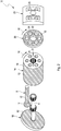
- a second possible embodiment of a fluid working machine 15, comprising a rotatable cylinder block 14, is shown in a schematic exploded view.
- some parts are not shown and/or are not shown in detail.
- identical reference numerals are used for parts that are similar in function. Therefore, an identical reference numeral does not necessarily imply that the respective parts are identical in function and/or have the same design in both embodiments.
- a fluid working machine 15 with a rotatable cylinder block 14 (as indicated by rotating arrows 16) is suggested that shows several surface coatings 12.
- the cylinder block 14 is rotated under the action of a turning shaft 4.
- Turning shaft 4 and cylinder block 14 are, for example, connected in a torque proof manner, using corresponding protrusions and indentations (for example in toothed wheel like manner).
- the tilted plate 18, on which the piston feet 17 of the pistons 5 rest is now arranged fixedly (i.e. not rotating). This does not necessarily rule out that the angle of the tilted plate 18 can possibly be changed during operation.
- the outer circumferential surface 19 of the cylinder block 14 shows a surface coating 12, since the outer circumferential surface 19 of the cylinder block 14 is in sliding arrangement with a corresponding supporting surface (not shown).
- the outer circumferential surfaces of the pistons 5 and the inner circumferential surfaces of the cylindrical cavities 6 show surface coatings 12 as well (necessitated by the sliding contact between the cylindrical cavities 6 and the pistons 5).
- the cylindrical cavities 6 are designed as simple through bores. It is easy to understand that such a design is particularly simple to manufacture. Therefore, "on top" of the cylinder block 14, a bearing plate 20 is arranged. The bearing plate 20 is fixed in a torque proof (and fluid tight) manner to the cylinder block 14. Thus, the bearing plate 20 rotates together with the cylinder block 14 (as indicated by rotating arrow 16). To realise a simple but effective torque proof connection between the cylinder block 14 and the bearing plate 20, protruding pins 21 that fit into corresponding holes 22 are presently used (of course, different arrangements can be used as well). The bearing plate 20 shows several openings 24, that are typically in fluid connection with the cylindrical cavities 6, but do not have the same cross sections as the cylindrical cavities 6.
- a valve plate 23 is arranged on the surface side of the bearing plate 16, lying opposite to the cylinder block 14 (and neighbouring the valve plate 23).
- the neighbouring surfaces of the bearing plate 20 and of the valve plate 23 are in sliding contact with each other. Consequently, the respective surfaces are provided with surface coatings 12.
- valve plate 23 is fixedly arranged (i.e. it is not rotating together with the cylinder block 14 and/or the bearing plate 20). As indicated in Fig. 2 , the valve plate 23 also shows several openings 25.
- the openings 25 in the valve plate 23 and the openings 24 in the bearing plate 20 are designed and arranged in a way that they "mimic the behaviour" of active and/or passive valves when the cylinder block 14/bearing plate 20 rotates with respect to the valve plate 24, so that a pumping behaviour and/or a motoring behaviour of the fluid working machine 15 is realised.
- Such a design is known as such in the state-of-the-art and presently not further described for brevity.
Landscapes
- Chemical & Material Sciences (AREA)
- Engineering & Computer Science (AREA)
- Mechanical Engineering (AREA)
- Materials Engineering (AREA)
- Metallurgy (AREA)
- Organic Chemistry (AREA)
- Chemical Kinetics & Catalysis (AREA)
- General Engineering & Computer Science (AREA)
- Plasma & Fusion (AREA)
- Physics & Mathematics (AREA)
- Combustion & Propulsion (AREA)
- Details Of Reciprocating Pumps (AREA)
- Coating By Spraying Or Casting (AREA)
- Reciprocating Pumps (AREA)
Description
- The invention relates to a workpiece for a hydraulic device that comprises at least in part a coating layer. Furthermore, the invention relates to a hydraulic device and/or a fluid working machine, comprising at least one workpiece that comprises at least in part a coating layer.
- Each time, when two surfaces of two different workpieces are in contact with each other, friction occurs. Initially, this friction hinders the movement of the respective workpieces, necessitating a comparatively high force to start a movement of the two workpieces relative to each other. As soon as movement has started, due to friction a mechanical wear of the two contacting surfaces inevitably occurs. This wear will ultimately result in the necessity of maintenance work (for example, the respective workpieces have to be replaced at a certain point), because otherwise at some point failure of the machinery will result. But even before failure occurs, the described wear (and in particular abrasion) of the respective surfaces will usually result in lower efficiency of the machine (for example due to higher losses of lubricant due to increased gaps), generation of noise (due to vibration, in particular due to a higher possible amplitude for vibrating parts), and the like, so that preventive maintenance sometimes has to be performed at a pretty early stage.
- Due to the function of the respective device, in which the workpieces are used, a relative movement of two machine parts (workpieces) usually cannot be avoided (because otherwise the machine would be inoperative). Therefore, other approaches have been suggested in the state of the art to reduce friction, thus prolonging maintenance intervals and increasing the performance of the device.
- A standard approach that is used in a plethora of technical fields is the use of lubricants. Thus, a thin fluid film is used at the interface of the two moving parts. As such fluids, a variety of oils (mineral oil, synthetic oil, a mixture of both and the like) are typically employed. However, the use of different types of fluid is also known in the state of the art. For example, in some applications a fluid layer consisting (mainly) of a gas (i.e. a thin gas film) is used for lubricating purposes as well.
- While this approach is the usual approach which works well in practice, it also has some disadvantages. In particular, an effective reduction of friction due to lubrication of the interface between the neighbouring parts will typically start only when the two surfaces of the workpieces move with a certain speed relative to each other. Then, so-called hydrodynamic lubrication occurs. At lower speeds, however, only so-called boundary lubrication occurs (which shows an increased friction and thus results in a higher wear). Between the two regimes, mixed lubrication occurs. The intrinsic problem of these regimes is that they somehow contradict, so that a compromise has to be designed. For completeness, it should be mentioned that under certain conditions dry friction can occur as well.
- In particular, to reduce friction (hydrodynamic lubrication) at higher speeds, oil with a low viscosity should be chosen. However, if the oil has a low viscosity, it is usually less adhesive and thus does not stick as well to the surface of the workpiece. This has the consequence that in the low-speed regime (boundary lubrication and/or mixed lubrication) usually a higher friction occurs, resulting in a higher wear. Thus, a compromise has to be found for the oil to be chosen, where the compromise depends highly on operating characteristics of the machinery in question.
- Another problem is that an oil film disappears from the surface of a machine that is not operating after a comparatively short time span. If the machine is not operating, of course a lubricating oil pump that pumps oil to the surfaces that have to be lubricated is inoperative as well. A typical time span for a surface to become dry is one to two days. After this period, typically the surface parts of a device show essentially no fluid coating and thus no fluid lubrication anymore. If the machine is started, for the initial time span a comparatively high friction and wear (inevitably) occurs, since the respective surface parts are in direct contact with each other (no fluid surface in between) for the initial phase of start-up (typically a few seconds). The same situation of a direct surface-to-surface contact (without any fluid film in between) can occur if a failure of (part of) the machinery occurs (for example failure of an oil pump) or even with an operative device under disadvantageous operating conditions.
- Therefore, for devices that necessitate a higher reliability and an increased lifetime, some additional measures have to be provided. A typical example for such an "additional measure" is the use of a special coating for the surface areas that are in moving contact with each other.
- Depending on the field of technology and thus the operating conditions of the contacting surfaces, a variety of surface coating layers have already been proposed.
- A particular field in technology is the field of fluid working machines (fluid pumping devices and/or fluid motoring devices, in particular hydraulic fluid pumps and/or hydraulic fluid motors). In this field, a variety of designs for fluid working machines exist. A sort of "challenging" design of fluid working machines (at least when it comes to surface coatings), are bent axis motors/bent axis pumps (including the further developed design of fluid working machines with a variable tilt angle of the tilted plate; this is referred to as a wobble plate). This is, because here by design a pin to surface contact is present. Therefore, apart from the necessities of good lubrication, a high mechanical force/pressure is existent. Therefore, one has to take into account several parameters.
- In particular, a low friction has to be present (with and without a fluid layer between the contacting surfaces), a good wettability of the surfaces with respect to the used lubricating fluid has to be present, a high mechanical resistance has to be present (low wear of the parts involved); and the respective coatings have to be able to tolerate a high mechanical force/high mechanical pressure (in particular without any so-called ploughing effects/deformation effects).
- So far, for this field of technology bronze coatings are used, where the bronze typically contains a certain percentage of lead. With increasing environmental awareness, however, the content of lead poses an increasing problem. In particular, it can be expected that the allowable lead content will be decreased over time by the legislator. Even a complete ban of any lead content has to be expected in the near future, at least under certain jurisdictions.
-
US 2012/119132 A1 discloses an article with a good wear resistance that includes a first component including a boride coating and a second component including a cobalt-chromium-molybdenum coating that is in sliding contact with the boride coating of the first component. - Other coatings are disclosed in Oerlikon Metco, "Material Product Data Sheet DSMTS-0107.0 - Mo(NiCrFeBSiC) Blended Powder for Thermal Spray", pages 1 - 3 and in Oerlikon Metco, "Material Product Data Sheet DSMTS-0046.1 (Metco 350NS: Fe 16Mo 2C 0.25Mn)".
- Therefore, there is an urgent need for a surface coating that shows good (or at least acceptable) mechanical properties, but that has no (or at least very little) lead content.
- Therefore, it is an object of the invention to propose a workpiece for a hydraulic device that comprises a coating layer, where the coating layer is improved over coating layers that are known in the state of the art. It is another object of the invention to propose a hydraulic device and/or a fluid working machine, comprising at least one workpiece that shows at least in part a coating layer that is improved over coating layers that are known in the state of the art.
- The invention according to the independent claims solves these objects.
- It is suggested to design a workpiece for a hydraulic device that comprises at least in part a coating layer in a way that the coating layer comprises the composition according to
claim 1. Although the workpiece that is intended to be used for hydraulic device can be essentially made of any material (just to name a few examples: a ceramic material, a resin material, a plastic material, a rubber material, a (carbon) reinforced fibre material, metal and the like; a mixture of two or more constituents of this list and/or possibly of even more substances is possible as well), it is usually advantageous if the workpiece is a metallic workpiece, i.e. that the basic material (that usually forms the basic structure of the respective material) is made of a metal. The metal can be essentially any metal. However, it is advantageous if it is made of metal that is regularly used for machines, for example iron, steel, stainless steel, copper, aluminium and the like (including, but not limited, alloys comprising one, two or even more of the previously mentioned metals and presumably some other materials and/or metals). The workpiece comprises at least one coating layer. In case a plurality of coating layers is provided (which is of course possible), those coating layers can be stacked "on top of each other" and/or they can be arranged on different surface areas of the workpiece ("side by side"). By the notion "comprising at least in part a coating layer", it has to be understood that not necessarily the complete surface of the workpiece has to comprise a coating layer. Instead, it is usually sufficient that the coating layer is arranged only on a fraction of the overall surface area of the workpiece, for example in form of one, two, three or even more "patches". In particular, the patches can advantageously cover (at least) those surface areas, where typically a surface contact to another workpiece takes place and/or can be expected to take place (in particular under more or less normal operating conditions of the complete device), possibly adding a "safety margin". To give some numbers about the fraction of the overall surface area of a certain part that can be covered with a surface coating layer: the surface coating layer (at least one of the plurality of surface coating layers) and cover at least 10%, 20%, 30%, 40%, 50%, 60%, 70%, 80%, 90% and/or up to 10%, 20%, 30%, 40%, 50%, 60%, 70%, 80%, 90% or 100%. Of course, it is possible that the coating layer (including the possibility of one or several patches of coating layers) shows essentially the same thickness. However, it is also possible that different thicknesses are used. To name a particular example, the coating layer can show a comparatively high thickness in a first fraction of the overall surface area, the coating layer can show a second, comparatively thin thickness in a second fraction of the overall surface area and in a third fraction of the overall surface area (essentially) no coating layer can be foreseen. It is even possible that even a fourth, fifth, sixth and so fraction of the overall surface area on shows coating layers of varying thicknesses as well. Furthermore, the first, the second and/or the third of the previously described coating layers can be dispensed with. To continue with the example of three surface fractions ("patches"), the first surface fraction with a comparatively thick coating layer can be arranged in regions, where a surface contact will frequently take place. The second surface fraction with a comparatively thin coating layer can be arranged in surface areas, where a surface contact can be expected less frequent (for example from time to time), while the third surface fraction with an extremely thin surface layer or no surface layer at all can be arranged in areas, where a surface contact is rarely expected (if at all). As mentioned, it is suggested that the coating layer contains Mo (i.e. molybdenum). - The molybdenum is present in form of metallic molybdenum. How (metallic) Mo is contained in the surface coating is essentially arbitrary. As an example, it can be present in form of small metallic droplets in a mixture of several compounds. However, it can be part of an alloy as well (where alloy cannot only be understood in a "narrow" sense, where essentially all constituents of the "overall material" are metals (or at least semi-metals). In particular, it is possible that molybdenum is part of a sintered material. It is once again noted that several layers and/or several "patches" (i.e. aside from each other) can be foreseen, where the different layers and/or different patches can be different, not only with respect to thickness, but also with respect to the material chosen (including the fraction of the respective compounds). The Mo has a weight fraction between 75% and 90%. First experiments have shown that the resulting coating layer shows a particularly advantageous behaviour, if molybdenum is present. In particular, by using molybdenum in the material mix (as presently potentially suggested) it is even possible to significantly reduce (and usually even to essentially completely avoid the use of) lead. Thus, present and future legislation can be dealt with, without unduly reducing the quality of the surface coating, and hence of the overall device (including the possibility of even increasing the reliability of the respective part(s), as it can be frequently realised). If the respective (metallic) workpiece is used for a hydraulic device, the use of molybdenum in the coating layer can show even more of its intrinsic properties and advantages, as first experiments have proven. In particular, the wettability of the coating layer is at least sufficiently high (and frequently even very high), when it comes to standard hydraulic oils. Therefore, the respective surfaces do not dry very fast, so that dry friction can be reduced, typically even significantly. Furthermore, using molybdenum as a constituent of the coating layer, usually a particularly wear-free coating layer can be realised that is usually very resistant toward "point-like forces" (i.e. with respect to high forces and/or high mechanical pressures that act on only a small surface area). This characteristic of the resulting coating layer is typically very welcome when it comes to hydraulic machines, in particular fluid working machines having a tilted plate that is in contact with piston feet.
- The thickness of the coating layer (at least one of the plurality of coating layers) is preferably in the range of approximately 200 µm. If a coating layer of such a thickness is applied, the fundamental mechanical characteristics of the workpiece are still similar to its uncoated equivalent (i.e. with respect to mechanical strength and so on), while the advantages of the surface coating, in particular with respect to abrasion strength and wear resistance, are already present (in particular a significant increase in strength will not increase those parameters significantly, at least under typical conditions; additionally or alternatively, even if only a thin coating layer is present, in particular in the range of approximately 200 µm as presently suggested, the coated workpieces usually show a high abrasion strength and wear resistance, even if high forces are present - normally no further thickening of the coating layer is necessary, albeit this is of course possible). Furthermore, cost can still be comparatively low (please mind that applying a coating using thermal coating techniques takes a significant time). Of course, different thicknesses can be applied as well. As an example, the thickness can be larger than 10 µm, 20 µm, 30 µm, 50 µm, 75 µm, 100 µm, 125 µm, 150 µm, 170 µm, 200 µm, 225 µm, 250 µm, 275 µm or 300 µm (as a lower limit; 0 is possible as well) and can go additionally and/or alternatively up to 50 µm, 75 µm, 100 µm, 125 µm, 150 µm, 175 µm, 200 µm, 225 µm, 250 µm, 275 µm, 300 µm, 325 µm, 350 µm, 375 µm, 400 µm, 425 µm, 450 µm, 475 µm, 500 µm, 600 µm, 700 µm, 800 µm, 900 µm or 1 mm (as an upper limit).
- The weight fraction of Mo in the coating layer is between 75% and 90%. The indicated figures can be applied to one, two, three or even more layers (including essentially all layers), in particular if a plurality of layers is prevalent. This statement shall possibly apply mutatis mutandis to all content indications (with respect to materials, percentages, chemical formulas, sizes (in particular sizes of particles and the like)) that are given in the context of this application, as well. First experiments have shown that the resulting workpiece will show a particularly advantageous overall characteristic, if the indicated percentages are chosen. In particular, the numbers can be chosen in dependence of the specific conditions the workpiece is intended to be used in.
- The coating layer (at least one of the plurality of coating layers) contains Ni (nickel) with a weight fraction between 2% and 5%. First experiments have shown that when using a certain content of Mo, the presence of Ni with a too high fraction is surprisingly counter-productive. Therefore, a reduced content of Ni is preferred. Only for completeness: the presently indicated numbers cannot only be used as an upper limit but additionally or alternatively as a lower limit as well.
- The coating layer (at least one of the plurality of coating layers) also contains Cr (chromium), B (boron), Si (silicon) and Fe (iron). First experiments indicate that by using a certain content of these materials (metals), will further improve the characteristics of the coating layer (in particular with respect to the presence of Mo to a certain extent).
- Furthermore, it is suggested that the workpiece is designed in a way that the coating layer (at least one of the plurality of coating layers) is essentially a material with the content formula Mo25(NiCrBSiFe), or a derivative thereof, where the weight content of Mo is between 75% and 90%, preferably between 80% and 85% and the weight content of Ni is between 2% and 5%, preferably between 3% and 4% and the weight content of Cr is between 2% and 5%, preferably between 3% and 4% and the weight content of B is between 2% and 5%, preferably between 3% and 4% and the weight content of Si is between 2% and 5%, preferably between 3% and 4% and the weight content of Fe is between 2% and 5%, preferably between 3% and 4%. First experiments have shown that this particular mixture of materials results in a particularly advantageous coating layer.
- The coating layer (at least one of the pluralities of coating layers) contains essentially no Pb (lead). This way, present and future legislation can be advantageously dealt with. By the notion "essentially no lead" it is meant that it is of course "allowed" that some residuals/impurities that cannot be economically feasibly removed (and that usually do not show a threat to nature) can be present in the respective material. Nevertheless, usually an "intentional content" of lead is avoided.
- According to yet another proposal, the workpiece can be designed in a way that the coating layer (at least one of the plurality of coating layers) is made from a spray material and preferably applied using spray coating methods, in particular thermal spray coating methods, like plasma spraying methods and/or high velocity oxy fuel spraying methods. Such methods are as such known in the state of the art as such (albeit with different materials). Using this proposal, it is possible that presently available machinery (and possibly even machinery that is already used "on site") can be used for the presently proposed coating layer (possibly after some modifications). This possibility increases the acceptance of the presently proposed coating layers. Nevertheless, using these (standard coating) methods, a coating layer of the presently proposed type, showing usually excellent characteristics, can be realised, typically in a comparatively cheap and efficient way.
- It is further suggested to design the workpiece in a way that the spray material comprises particles of sizes that are suitable for spray coating methods, in particular in that the spray material comprises particles with sizes in the range from 1 µm to 25 µm, preferably between 5 µm and 15 µm. In the present context, "comprising" can be understood as (essentially) consisting of. Also, a certain percentage of at least 0%, 10%, 20%, 30%, 40%, 50%, 60%, 70%, 80% or 90% up to 10%, 20%, 30%, 40%, 50%, 60%, 70%, 80%, 90% or 100% can be meant as well. The percentage can particularly relate to a weight percentage, to a molar percentage, to a volume percentage or the like. Using particles of such a size, usually the resulting coating layer shows particularly advantageous characteristics; in particular, it is usually very wear resistant. It is to be noted that the particles, although they are a "predecessor material" of the resulting coating layer, will influence the structure of the resulting coating layer in a way that the originally used sizes can still be detected from the resulting coating layer, at least under usually employed operating conditions of the spray coating methods.
- The workpieces (and in particular the coating layer/coating layers) can show their intrinsic properties and advantages particularly well, if in the workpiece, the coating layer (at least one of the plurality of coating layers) is present at least at a contacting surface, where the workpiece is movably arranged relative to another workpiece. As already mentioned, this is sort of a "typical minimum requirement". At different regions, a coating layer may or may not be present and/or a coating layer of a different thickness and/or of a different material composition may be foreseen. The "contacting surface" in this context is to be interpreted in a way that a mechanical contact under standard operating conditions (and possibly under operating conditions that are rare - and therefore not standard - but that can occur with a reasonably high level of possibility) is envisaged. In the present context, the notion of a "contacting surface" can particularly mean a direct contact (with no lubricant in between) and/or an "indirect" contact (with a lubricant layer in between).
- It is further suggested to design the workpiece in a way that the workpiece is a device, taken from the group comprising swash plates, eccentrics, pistons, piston feet, cylinders, cylinder blocks, valves, valve plates, valve plate devices, valve segment devices, rings, liners, plates, plate devices, bearings, bearing plates and/or bearing plate devices. Such parts are typically particularly prone to mechanical wear. Therefore, the use of a coating layer for such parts is particularly advantageous and will usually result in a very durable "overall machine". This, of course, is usually desired. It is to be noted that even when the notion of a "plate" is used, it is also possible that the respective device has a profound thickness (where usually the notion of a "plate" would not be used). Therefore, for some of the devices listed above, alternative expressions are suggested (like plate device, valve segment, valve segment device). The respective notions have not been used for all possible and thinkable combinations. However, the use shall be possible mutatis mutandis for other devices as well. In particular, the use of "plate" is typically limited to devices with a thickness of up to 1 mm, 2 mm, 3 mm, 4 mm, 5 mm, 6 mm, 7 mm, 8 mm, 9 mm or 10 mm. In the "other direction", plates of a very limited thickness shall be possible as well, where sometimes the notion of a "foil" might already be used (for example for devices of up to 0.1 mm, 0.2 mm, 0.3 mm, 0.4 mm, 0.5 mm, 0.6 mm, 0.7 mm, 0.8 mm, 0.9 mm or 1 mm). Of course, it is clear for a person skilled in the art that the "upper limit" for one device can be interpreted as the "lower limit" for the "consecutive" device.
- It is further suggested that the workpiece is designed for use in a hydraulic device, in particular for use in a fluid working machine. In such a case, the respective workpiece can show its intrinsic properties and advantages particularly well, resulting in a likewise advantageous "overall machine".
- Furthermore, it is suggested to design a hydraulic device and/or a fluid working machine in a way that it comprises at least one workpiece according to one or several of the previous suggestions. In this case, the hydraulic device/the fluid working machine shows the same characteristics, advantages and features as previously mentioned, at least in analogy. Furthermore, the hydraulic device/fluid working machine can be improved in the previously described sense as well, at least in analogy.
- Further advantages, features, and objects of the invention will be apparent from the following detailed description of the invention in conjunction with the associated drawings, wherein the drawings show:
- Fig. 1:
- a possible first embodiment of a fluid working machine comprising several parts, where some of those parts show a partial surface coating, in a schematic cross section;
- Fig. 2:
- a possible second embodiment of a fluid working machine comprising several parts, where some of those parts show a partial surface coating, in a schematic exploded view.
- In
Fig. 1 , a possible embodiment of afluid working machine 1 is shown. In the present case, thefluid working machine 1 is of a hydraulic fluid pump type, where a tilted swash plate 2 (frequently addressed as "wobble plate") is used for first converting a rotary movement 3 (indicated byarrow 3 around turning shaft 4) into an up-and-down movement ofseveral pistons 5 that move in their respectivecylindrical cavities 6. Thecylindrical cavities 6 are arranged in avalve block 14 that remains stationary. By the up-and-down movement of thepistons 5, the volume that is enclosed by thepistons 5 and thecylindrical cavity 6 is repetitively expanding and contracting. Furthermore,fluid inlet channels 7 andfluid outlet channels 8 fluidly connect to thecylindrical cavities 6 with appropriately arrangedcheck valves 9 arranged in thefluid channels fluid working machine 1 of the embodiment shown, thevalve block 14 remains (essentially) stationary. However, it is of course not ruled out that thefluid working machine 1 is used for mobile applications. Therefore, in the context of the present application "stationary" or "fixedly" are typically to be interpreted with respect to the imminent environment (for example with respect to the reference frame of a vehicle). As an additional remark, different designs apart from the presently shown design withcheck valves 9 are certainly possible as well. Just to name another possibility: a valve plate (valve plate device, valve segment, or the like) could be used additionally and/or alternatively. - Based on the repetitive expansion and contraction of the fluid volume enclosed by the
cylindrical cavities 6 and thepistons 5, fluid will be pumped from alow pressure reservoir 10 to a high pressure reservoir 11 (presently not shown in detail), when rotary action is performed on therotating shaft 4. Such a device is as such known in the state of the art. - The invention lies in the surface coating 12 (indicated by hatched areas) that is arranged on parts of the pistons 5 (cylindrical part), parts of the inside walls of the
cylindrical cavities 6, parts of the surface of theswash plate 2 and parts of the surface of the contactingballs 13 that are arranged on the lower parts of thepistons 5, where the contactingballs 13 are designed to be in driving contact with theswash plate 2. - It is to be understood that (at least part of) the gist of the invention lies in the various parts that show a surface coating as discussed later on and the surface coating itself.
- It has to be also understood that the
various surface coatings 12 can of course be applied to different parts and/or for different embodiments of thefluid working machine 1 as well. In particular, when additionally and/or alternatively to the presently showncheck valves 9, a valve plate (or similar device) is used, additional and/or other surface parts should preferably show a surface coating (while some surface parts might not need a surface coating any more). - Furthermore, such appropriately coated parts can be used for different machinery as well. To just name a few examples from the technical field of hydraulics: the parts could be used for hydraulic pumps, for hydraulic motors, for combined hydraulic pumps/motors, for fluid working machines (pumps, motors, combined pumps and motors) of various designs like a tilted plate type; a type with a twistable tilted plate; a fluid working machine using an eccentric that is driving piston feet; a fluid working machine with a rotating cylinder block; a fluid working machine with a valve plate (or a similar device); and so on (where a fluid working machine showing a combination of the aforesaid and possibly even more features is possible as well). Surface coatings in the presently shown embodiment have a thickness of some 200 µm (where some variations can of course occur). Furthermore, it is usually not too problematic if the
surface coatings 12 show some variations with respect to their thickness. For example, a nominal surface thickness of (let's say) 200 µm show some variations between 190 µm and 210 µm or even 180 µm to 220 µm without resulting in any noticeable adverse effects (at least usually). - The
surface coating 12 is presently applied using a plasma spraying technique, a method that is well known in the state of the art. Presently, for plasma spraying particles of a size of some 10 µm are used (with some variations of ± 5 µm). However, the invention is not limited to such sizes and/or to a plasma spray coating method. Essentially all coating techniques can be used likewise, in particular HVOF-techniques (high velocity oxy fuel spraying). Additionally and/or alternatively, particles of a different size can be used as well. - In the present embodiment plasma spraying is based on an arc formation between an anode and a cathode, which leads to the ionisation of a reaction gas, forming a plasma. The coating material is introduced into the plasma and melted due to the high temperature it experiences by those conditions. However, the exact details can vary, of course.
- The
surface coatings 12 of some surface areas of some parts of thefluid working machine 1 are only applied on those surface parts, where a high probability of a sliding contact between two different parts is present (i.e. such surface areas, where during use of the fluid working machine a relative movement between two different surface parts will usually take place). - In the present embodiment, the
surface coatings 12 are therefore limited to the upper side of the swash plate 2 (neighbouring thepistons 5 and the block in which thecylindrical cavities 6 are arranged). On this surface side of theswash plate 2, contactingballs 13 that are arranged on the lower side of thevarious pistons 5 are in driving contact with the (turning)swash plate 2. Furthermore, the lower half spheres of the contactingballs 13 show asurface coating 12 as well. It is easily understandable that by thesurface coatings 12 on the upper side of theswash plate 2 and on the lower spherical half of the contactingballs 13 all surface parts of the contactingballs 13 of theswash plate 2 that can come into sliding contact with each other during normal operation conditions of the workingmachine 1 show asurface coating 12 in between. Therefore, only a sliding contact between surface coatings is present here (where, of course, a dry sliding without any hydraulic oil can occur in certain operating conditions, like in a malfunction of an oil pump, under severe load and/or in very adverse operating conditions and/or when the fluid working machine has just been started and the oil circuit has been not yet been fully established). - Nevertheless, due to the
surface coatings 12, even when dry friction between the contacting surfaces occurs, a lower friction and a lower wear occurs as compared to the case, where no surface coating is present and the (typically metal)parts - The big advantage of the presently used
surface coating 12 is that it is essentially lead-free, i.e. that (apart from some residual contaminations) the surface coating does not contain any lead. - As a remark it should be noted that it is even sufficient that the top surface of the
swash plate 2 shows only a ring-like coating so that a sliding contact between the contactingballs 13 and theswash plate 2 is only established with surface parts, showing a surface coating. However, applying only a ring on top of the swash plate is usually comparatively difficult to achieve. Therefore, it is usually cheaper to coat the complete top surface of theswash plate 2. Likewise, additional surface parts of the various parts that are shown inFig. 1 could be covered with a surface coating as well (to name an example, thepistons 5 could be "completely covered" with a surface coating). - As can be seen from
Fig. 1 ,surface coatings 12 are also applied on the (outer) cylindrical surfaces of thepistons 5 and on the (inner) cylindrical surfaces of thecylindrical cavities 6. As it is easily understandable, here a sliding movement between the contacting surfaces of thepistons 5 and thecylindrical cavities 6 occurs when thepistons 5 are moving up and down under typical operating conditions of thefluid working machine 1. - Presently, two specific embodiments of
surface coatings 12 have been investigated and measured, and the results have been compared to presently used surface coatings, comprising a bronze layer with a lead content. - In particular, as substance 1 a material with the content formula Mo25 (NiCrBSiFe) was used, while as an illustrative
second substance 2, not according to the invention, a material with the content formula Fe16Mo2C0.25Mn was used. - The surface coating was applied with a nominal thickness of 200 µm. This was compared to a lead-containing bronze, as it is available in the state of the art. The lead-containing bronze was also applied with a nominal thickness of 200 µm.
- All surface coatings have been applied on a C22 steel substrate according to DIN EN 10083-2, consisting of pearlite and ferrite phases. The hardness of the substrate was given by 195±4 HV0.2, and the flatness was quoted to be 13.38±1,08 µm. Measurements showed that the roughness of the respective coatings after lapping is according to table 1.
Rpk/µm Rk/µm Rvk/µm Lead-containing bronze 0.503±0.013 1.17±0.013 0.666±0.014 Substance 10.136±0.007 0.664±0.01 1.57±0.079 Substance 20.457±0.016 1.858±0.031 2.356±0.128 - When measurements were performed, the micro hardness measurements (HV0.2) on the basis of a metallographic cut was 126 for the reference lead-containing bronze layer, while for
substance 1 the micro hardness was approximately 500 HV0.2 and forsubstance 2 the micro hardness was approximately 460 HV0.2. Likewise, the adhesive strength of the thermally sprayed coatings was measured to be 37 N/mm2 forsubstance 1 and 41 N/mm2 forsubstance 2. - The seizure test (coefficient of friction against time) showed a coefficient of friction of approximately 0.11 after 60 sec. of test run for both substances (
substance 1 and 2) which is almost the same as for lead-containing bronze according to the state of the art (0.11 after 60 sec. as well). - Finally, the critical contact pressure to the end of the seizure test is even advantageous over lead-containing bronze. While the lead-containing bronze layer showed a critical contact pressure of 650 N/mm2,
substance 1 showed a critical contact pressure of 1250 N/mm2, whilesubstance 2 showed a critical contact pressure of 1070 N/mm2. - In short, it can be seen that the presently investigated materials, both containing molybdenum to a certain relevant extent, show even mechanical advantages over presently used lead-containing bronze. The advantage of environmental friendliness due to the absence of lead is of course obvious.
- As already mentioned above, the afore described and/or presently suggested
surface coatings 12 can be advantageously used for other surfaces, parts, devices, surface parts, fluid working machines and/or so on. Therefore, to elucidate the present invention and its advantages and applicability in more detail, in the following, a second possible embodiment of afluid working machine 15 will be described with reference toFig 2 . In particular, some kind of a "combination" of the embodiments of afluid working machine 1 according toFig. 1 and of afluid working machine 15 according toFig. 2 is possible as well (in particular by combining certain features), although this is not explicitly described. Such a "combination" is of course not limited to the presently shown and described embodiments of afluid working machine - In
Fig. 2 , a second possible embodiment of afluid working machine 15, comprising arotatable cylinder block 14, is shown in a schematic exploded view. For the sake of clarity, some parts are not shown and/or are not shown in detail. Furthermore, for the sake of simplicity, identical reference numerals are used for parts that are similar in function. Therefore, an identical reference numeral does not necessarily imply that the respective parts are identical in function and/or have the same design in both embodiments. - According to the embodiment of
Fig. 2 , afluid working machine 15 with a rotatable cylinder block 14 (as indicated by rotating arrows 16) is suggested that showsseveral surface coatings 12. - In operation, the
cylinder block 14 is rotated under the action of a turningshaft 4. Turningshaft 4 andcylinder block 14 are, for example, connected in a torque proof manner, using corresponding protrusions and indentations (for example in toothed wheel like manner). To "compensate" for the now-rotating cylinder block 14 (as compared to the embodiment ofFig. 1 ), the tiltedplate 18, on which thepiston feet 17 of thepistons 5 rest (inFig. 2 only asingle piston 5 is shown for simplicity), is now arranged fixedly (i.e. not rotating). This does not necessarily rule out that the angle of the tiltedplate 18 can possibly be changed during operation. - When the
rotating cylinder block 14 rotates, thepistons 5 are carried along together with therotating cylinder block 14. Therefore, thepiston feet 17 slide along the tiltedplate 18 and move up-and-down due to the inclination of the tiltedplate 18. Therefore, thepistons 5 move back and forth in their respectivecylindrical cavities 6 that are arranged inside thecylinder block 14. This translates into an internal volume of a repetitively changing size that can be used for pumping hydraulic fluid and/or for transforming pressure energy into a movement (similar to the embodiment of afluid working machine 1 according toFig. 1 ). - As a consequence of the rotation of the
cylinder block 14, the outercircumferential surface 19 of thecylinder block 14 shows asurface coating 12, since the outercircumferential surface 19 of thecylinder block 14 is in sliding arrangement with a corresponding supporting surface (not shown). Of course, the outer circumferential surfaces of thepistons 5 and the inner circumferential surfaces of thecylindrical cavities 6show surface coatings 12 as well (necessitated by the sliding contact between thecylindrical cavities 6 and the pistons 5). - In the presently shown embodiment, the
cylindrical cavities 6 are designed as simple through bores. It is easy to understand that such a design is particularly simple to manufacture. Therefore, "on top" of thecylinder block 14, a bearingplate 20 is arranged. The bearingplate 20 is fixed in a torque proof (and fluid tight) manner to thecylinder block 14. Thus, the bearingplate 20 rotates together with the cylinder block 14 (as indicated by rotating arrow 16). To realise a simple but effective torque proof connection between thecylinder block 14 and the bearingplate 20, protruding pins 21 that fit into corresponding holes 22 are presently used (of course, different arrangements can be used as well). The bearingplate 20 shows several openings 24, that are typically in fluid connection with thecylindrical cavities 6, but do not have the same cross sections as thecylindrical cavities 6. - On the surface side of the bearing
plate 16, lying opposite to the cylinder block 14 (and neighbouring the valve plate 23), avalve plate 23 is arranged. The neighbouring surfaces of the bearingplate 20 and of thevalve plate 23 are in sliding contact with each other. Consequently, the respective surfaces are provided withsurface coatings 12. - The
valve plate 23 is fixedly arranged (i.e. it is not rotating together with thecylinder block 14 and/or the bearing plate 20). As indicated inFig. 2 , thevalve plate 23 also showsseveral openings 25. - The
openings 25 in thevalve plate 23 and the openings 24 in the bearingplate 20 are designed and arranged in a way that they "mimic the behaviour" of active and/or passive valves when thecylinder block 14/bearing plate 20 rotates with respect to the valve plate 24, so that a pumping behaviour and/or a motoring behaviour of thefluid working machine 15 is realised. Such a design is known as such in the state-of-the-art and presently not further described for brevity. - Thanks to the
various surface coatings 12 on the various surface parts of the various parts of thefluid working machine 15, a reliable and wear resistantfluid working machine 15 with a long lifetime and comparatively low friction can be realised. -
- 1.
- Fluid working machine
- 2.
- Swash plate
- 3.
- Arrow
- 4.
- Turning shaft
- 5.
- Piston
- 6.
- Cylindrical cavity
- 7.
- Fluid inlet channel
- 8.
- Fluid outlet channel
- 9.
- Check valve
- 10.
- Low pressure reservoir
- 11.
- High pressure reservoir
- 12.
- Surface coating
- 13.
- Contacting balls
- 14.
- Cylinder block
- 15.
- fluid working machine
- 16.
- rotating arrow
- 17.
- piston foot
- 18.
- tilted plate
- 19.
- outer circumferential surface
- 20.
- bearing plate
- 21.
- pin
- 22.
- hole
- 23.
- valve plate
- 24.
- opening (of bearing plate)
- 25.
- opening (of valve plate)
Claims (10)
- Workpiece (2, 5, 6, 14, 20, 23) for a hydraulic device (1, 15), comprising at least in part a coating layer (12), characterized in that the coating layer (12) contains Mo with a weight fraction between 75% and 90%, Ni with a weight fraction between 2% and 5%, Cr with a weight fraction between 2% and 5%, B with a weight fraction between 2% and 5%, Si with a weight fraction between 2% and 5% and Fe with a weight fraction between 2% and 5%, and essentially no Pb, the constituents adding up to 100%.
- Workpiece (2, 5, 6, 14, 20, 23) according to claim 1, characterized in that the weight fraction of Mo in the coating layer (12) is between 80% and 85% and/or the weight content of Ni is between 3% and 4%.
- Workpiece (2, 5, 6, 14, 20, 23) according to claim 1 or 2, characterized in that the weight content of Cr is between 3% and 4% and/or the weight content of B is between 3% and 4% and/or the weight content of Si is between 3% and 4% and/or the weight content of Fe is between 3% and 4%,
- Workpiece (2, 5, 6, 14, 20, 23) according to claim 1, characterized in that the coating layer (12) is essentially a material with the content formula Mo25(NiCrBSi Fe).
- Workpiece (2, 5, 6, 14, 20, 23) according to any of the preceding claims, characterized in that the coating layer (12) is made from a spray material and preferably applied using spray coating methods, in particular thermal spray coating methods, like plasma spraying methods and/or high velocity oxy fuel spraying methods.
- Workpiece (2, 5, 6, 14, 20, 23) according to claim 5, characterized in that the spray material comprises particles of sizes that are suitable for spray coating methods, in particular in that the spray material comprises particles with sizes in the range from 1 µm to 25 µm, preferably between 5 µm and 15 µm.
- Workpiece (2, 5, 6, 14, 20, 23) according to any of the preceding claims characterized that the coating layer (12) is present at least at a contacting surface, where the workpiece (2, 5, 6, 14, 20, 23) is movably arranged relative to another workpiece (2, 5, 6, 14, 20, 23).
- Workpiece (2, 5, 6, 14, 20, 23) according to any of the preceding claims, characterized in that it is a device, taken from the group comprising swash plates (2), eccentrics, pistons (5), piston feet (13, 17), cylinders (6), cylinder blocks (14), valves, valve plates (23), valve plate devices, valve segment devices, rings, liners, plates, bearings and/or bearing plate devices (20).
- Workpiece (2, 5, 6, 14, 20, 23) according to any of the preceding claims, in particular according to claim 8, characterized in that it is designed for use in a hydraulic device (1, 15), in particular for use in a fluid working machine (1, 15).
- Hydraulic device and/or fluid working machine, characterized by at least one workpiece (2, 5, 6, 14, 20, 23) according to any of the preceding claims.
Applications Claiming Priority (2)
| Application Number | Priority Date | Filing Date | Title |
|---|---|---|---|
| DE102016108408.5A DE102016108408B4 (en) | 2016-05-06 | 2016-05-06 | Workpiece with improved coating and hydraulic device and/or fluid working machine with the workpiece |
| PCT/EP2017/059135 WO2017190941A1 (en) | 2016-05-06 | 2017-04-18 | Workpiece with improved coating |
Publications (2)
| Publication Number | Publication Date |
|---|---|
| EP3452628A1 EP3452628A1 (en) | 2019-03-13 |
| EP3452628B1 true EP3452628B1 (en) | 2020-07-22 |
Family
ID=58671577
Family Applications (1)
| Application Number | Title | Priority Date | Filing Date |
|---|---|---|---|
| EP17721539.9A Not-in-force EP3452628B1 (en) | 2016-05-06 | 2017-04-18 | Workpiece with improved coating |
Country Status (6)
| Country | Link |
|---|---|
| US (1) | US11346007B2 (en) |
| EP (1) | EP3452628B1 (en) |
| JP (1) | JP6609040B2 (en) |
| CN (1) | CN108138299A (en) |
| DE (1) | DE102016108408B4 (en) |
| WO (1) | WO2017190941A1 (en) |
Families Citing this family (3)
| Publication number | Priority date | Publication date | Assignee | Title |
|---|---|---|---|---|
| CN108979994A (en) * | 2018-07-26 | 2018-12-11 | 佛山三水鼎力液压机械设备有限公司 | A kind of ultrahigh-pressure hydraulic plunger pump of high efficiency and heat radiation |
| CN110923563B (en) * | 2019-12-17 | 2021-06-25 | 扬州神驰新材料科技有限公司 | Wear-resistant cylinder sleeve for diesel engine and preparation process thereof |
| EP4375505A1 (en) * | 2022-11-28 | 2024-05-29 | Danfoss A/S | Control plate of a hydraulic machine and hydraulic machine |
Family Cites Families (10)
| Publication number | Priority date | Publication date | Assignee | Title |
|---|---|---|---|---|
| US3690686A (en) | 1969-08-11 | 1972-09-12 | Ramsey Corp | Piston with seal having high strength molybdenum alloy facing |
| DE3515107C1 (en) * | 1985-04-26 | 1986-07-31 | Goetze Ag, 5093 Burscheid | Spray powder for the production of wear-resistant and escape-proof coatings |
| US4599861A (en) * | 1985-05-13 | 1986-07-15 | Beaumont Richard W | Internal combustion hydraulic engine |
| EP0858519B1 (en) * | 1995-10-31 | 2000-05-10 | Volkswagen Aktiengesellschaft | Method of producing a sliding surface on a metal workpiece |
| JP3556139B2 (en) * | 1999-11-18 | 2004-08-18 | 株式会社神戸製鋼所 | Wear-resistant cast steel and method for producing the same |
| US6652674B1 (en) | 2002-07-19 | 2003-11-25 | United Technologies Corporation | Oxidation resistant molybdenum |
| JP4289926B2 (en) * | 2003-05-26 | 2009-07-01 | 株式会社小松製作所 | Sliding material, sliding member, sliding component, and apparatus to which the sliding material is applied |
| US8833382B2 (en) * | 2010-11-11 | 2014-09-16 | Hamilton Sundstrand Corporation | Article having good wear resistance |
| KR101316474B1 (en) * | 2011-09-19 | 2013-10-08 | 현대자동차주식회사 | Valve seat of engine and manufacturing method therof |
| CN102787933A (en) * | 2012-08-29 | 2012-11-21 | 芜湖鼎恒材料技术有限公司 | Air cylinder with nano alloy coating |
-
2016
- 2016-05-06 DE DE102016108408.5A patent/DE102016108408B4/en not_active Expired - Fee Related
-
2017
- 2017-04-18 EP EP17721539.9A patent/EP3452628B1/en not_active Not-in-force
- 2017-04-18 JP JP2018512149A patent/JP6609040B2/en not_active Expired - Fee Related
- 2017-04-18 CN CN201780003078.0A patent/CN108138299A/en active Pending
- 2017-04-18 WO PCT/EP2017/059135 patent/WO2017190941A1/en not_active Ceased
- 2017-04-18 US US15/763,313 patent/US11346007B2/en active Active
Non-Patent Citations (1)
| Title |
|---|
| None * |
Also Published As
| Publication number | Publication date |
|---|---|
| DE102016108408A1 (en) | 2017-11-09 |
| US11346007B2 (en) | 2022-05-31 |
| EP3452628A1 (en) | 2019-03-13 |
| JP2018536762A (en) | 2018-12-13 |
| WO2017190941A1 (en) | 2017-11-09 |
| JP6609040B2 (en) | 2019-11-20 |
| CN108138299A (en) | 2018-06-08 |
| US20180282878A1 (en) | 2018-10-04 |
| DE102016108408B4 (en) | 2023-10-26 |
Similar Documents
| Publication | Publication Date | Title |
|---|---|---|
| EP2994655B1 (en) | Sliding engine component | |
| EP2932112B1 (en) | Thrust washer | |
| US20120128284A1 (en) | Slide bearing, a manufacturing process and an internal combustion engine | |
| US10066670B2 (en) | Plain bearing composite material | |
| EP2833008B1 (en) | Sliding member | |
| US20060083451A1 (en) | Sliding bearing | |
| US6895855B2 (en) | Hydraulic motors and pumps with engineered surfaces | |
| US11346007B2 (en) | Workpiece with improved coating | |
| EP2350503B1 (en) | Hydrodynamic circumferential seal system for large translations | |
| US20130307221A1 (en) | Piston ring | |
| JP2007285300A (en) | Adjustable rotary pump reducing wear | |
| EP2863080B1 (en) | Half bearing | |
| US20150300333A1 (en) | Hydraulic Rotary Machine | |
| US20080110331A1 (en) | cam ring for an injection pump | |
| CN103890420A (en) | Thermal Spray Coating of Plain Bearing Linings | |
| CN112204279A (en) | Shaft sealing device | |
| US7284537B2 (en) | High-pressure pump for a fuel-injection device of an internal combustion engine | |
| US9605713B2 (en) | Sliding bearing with bearing substrate and polymer in-fill | |
| JP5910438B2 (en) | Half thrust bearing | |
| JP5376668B2 (en) | piston ring | |
| CN105518320A (en) | Bearing shell | |
| KR102367180B1 (en) | Half-half thrust bearings, thrust bearings, bearing devices and internal combustion engines | |
| RU2477395C1 (en) | Energy-saving sliding bearing | |
| CN117108623A (en) | Bearing and method of manufacture | |
| EP2898237B1 (en) | Piston ring, piston comprising such ring and piston machine comprising at least one such piston |
Legal Events
| Date | Code | Title | Description |
|---|---|---|---|
| STAA | Information on the status of an ep patent application or granted ep patent |
Free format text: STATUS: UNKNOWN |
|
| STAA | Information on the status of an ep patent application or granted ep patent |
Free format text: STATUS: THE INTERNATIONAL PUBLICATION HAS BEEN MADE |
|
| PUAI | Public reference made under article 153(3) epc to a published international application that has entered the european phase |
Free format text: ORIGINAL CODE: 0009012 |
|
| STAA | Information on the status of an ep patent application or granted ep patent |
Free format text: STATUS: REQUEST FOR EXAMINATION WAS MADE |
|
| 17P | Request for examination filed |
Effective date: 20180425 |
|
| AK | Designated contracting states |
Kind code of ref document: A1 Designated state(s): AL AT BE BG CH CY CZ DE DK EE ES FI FR GB GR HR HU IE IS IT LI LT LU LV MC MK MT NL NO PL PT RO RS SE SI SK SM TR |
|
| AX | Request for extension of the european patent |
Extension state: BA ME |
|
| DAV | Request for validation of the european patent (deleted) | ||
| DAX | Request for extension of the european patent (deleted) | ||
| STAA | Information on the status of an ep patent application or granted ep patent |
Free format text: STATUS: EXAMINATION IS IN PROGRESS |
|
| 17Q | First examination report despatched |
Effective date: 20191001 |
|
| GRAP | Despatch of communication of intention to grant a patent |
Free format text: ORIGINAL CODE: EPIDOSNIGR1 |
|
| STAA | Information on the status of an ep patent application or granted ep patent |
Free format text: STATUS: GRANT OF PATENT IS INTENDED |
|
| INTG | Intention to grant announced |
Effective date: 20200327 |
|
| GRAS | Grant fee paid |
Free format text: ORIGINAL CODE: EPIDOSNIGR3 |
|
| GRAA | (expected) grant |
Free format text: ORIGINAL CODE: 0009210 |
|
| STAA | Information on the status of an ep patent application or granted ep patent |
Free format text: STATUS: THE PATENT HAS BEEN GRANTED |
|
| AK | Designated contracting states |
Kind code of ref document: B1 Designated state(s): AL AT BE BG CH CY CZ DE DK EE ES FI FR GB GR HR HU IE IS IT LI LT LU LV MC MK MT NL NO PL PT RO RS SE SI SK SM TR |
|
| REG | Reference to a national code |
Ref country code: GB Ref legal event code: FG4D |
|
| REG | Reference to a national code |
Ref country code: CH Ref legal event code: EP |
|
| REG | Reference to a national code |
Ref country code: DE Ref legal event code: R096 Ref document number: 602017020171 Country of ref document: DE |
|
| REG | Reference to a national code |
Ref country code: AT Ref legal event code: REF Ref document number: 1293452 Country of ref document: AT Kind code of ref document: T Effective date: 20200815 |
|
| REG | Reference to a national code |
Ref country code: IE Ref legal event code: FG4D |
|
| REG | Reference to a national code |
Ref country code: LT Ref legal event code: MG4D |
|
| REG | Reference to a national code |
Ref country code: AT Ref legal event code: MK05 Ref document number: 1293452 Country of ref document: AT Kind code of ref document: T Effective date: 20200722 |
|
| PG25 | Lapsed in a contracting state [announced via postgrant information from national office to epo] |
Ref country code: GR Free format text: LAPSE BECAUSE OF FAILURE TO SUBMIT A TRANSLATION OF THE DESCRIPTION OR TO PAY THE FEE WITHIN THE PRESCRIBED TIME-LIMIT Effective date: 20201023 Ref country code: ES Free format text: LAPSE BECAUSE OF FAILURE TO SUBMIT A TRANSLATION OF THE DESCRIPTION OR TO PAY THE FEE WITHIN THE PRESCRIBED TIME-LIMIT Effective date: 20200722 Ref country code: SE Free format text: LAPSE BECAUSE OF FAILURE TO SUBMIT A TRANSLATION OF THE DESCRIPTION OR TO PAY THE FEE WITHIN THE PRESCRIBED TIME-LIMIT Effective date: 20200722 Ref country code: HR Free format text: LAPSE BECAUSE OF FAILURE TO SUBMIT A TRANSLATION OF THE DESCRIPTION OR TO PAY THE FEE WITHIN THE PRESCRIBED TIME-LIMIT Effective date: 20200722 Ref country code: FI Free format text: LAPSE BECAUSE OF FAILURE TO SUBMIT A TRANSLATION OF THE DESCRIPTION OR TO PAY THE FEE WITHIN THE PRESCRIBED TIME-LIMIT Effective date: 20200722 Ref country code: LT Free format text: LAPSE BECAUSE OF FAILURE TO SUBMIT A TRANSLATION OF THE DESCRIPTION OR TO PAY THE FEE WITHIN THE PRESCRIBED TIME-LIMIT Effective date: 20200722 Ref country code: AT Free format text: LAPSE BECAUSE OF FAILURE TO SUBMIT A TRANSLATION OF THE DESCRIPTION OR TO PAY THE FEE WITHIN THE PRESCRIBED TIME-LIMIT Effective date: 20200722 Ref country code: PT Free format text: LAPSE BECAUSE OF FAILURE TO SUBMIT A TRANSLATION OF THE DESCRIPTION OR TO PAY THE FEE WITHIN THE PRESCRIBED TIME-LIMIT Effective date: 20201123 Ref country code: BG Free format text: LAPSE BECAUSE OF FAILURE TO SUBMIT A TRANSLATION OF THE DESCRIPTION OR TO PAY THE FEE WITHIN THE PRESCRIBED TIME-LIMIT Effective date: 20201022 Ref country code: NO Free format text: LAPSE BECAUSE OF FAILURE TO SUBMIT A TRANSLATION OF THE DESCRIPTION OR TO PAY THE FEE WITHIN THE PRESCRIBED TIME-LIMIT Effective date: 20201022 |
|
| PG25 | Lapsed in a contracting state [announced via postgrant information from national office to epo] |
Ref country code: PL Free format text: LAPSE BECAUSE OF FAILURE TO SUBMIT A TRANSLATION OF THE DESCRIPTION OR TO PAY THE FEE WITHIN THE PRESCRIBED TIME-LIMIT Effective date: 20200722 Ref country code: RS Free format text: LAPSE BECAUSE OF FAILURE TO SUBMIT A TRANSLATION OF THE DESCRIPTION OR TO PAY THE FEE WITHIN THE PRESCRIBED TIME-LIMIT Effective date: 20200722 Ref country code: LV Free format text: LAPSE BECAUSE OF FAILURE TO SUBMIT A TRANSLATION OF THE DESCRIPTION OR TO PAY THE FEE WITHIN THE PRESCRIBED TIME-LIMIT Effective date: 20200722 Ref country code: IS Free format text: LAPSE BECAUSE OF FAILURE TO SUBMIT A TRANSLATION OF THE DESCRIPTION OR TO PAY THE FEE WITHIN THE PRESCRIBED TIME-LIMIT Effective date: 20201122 |
|
| PG25 | Lapsed in a contracting state [announced via postgrant information from national office to epo] |
Ref country code: NL Free format text: LAPSE BECAUSE OF FAILURE TO SUBMIT A TRANSLATION OF THE DESCRIPTION OR TO PAY THE FEE WITHIN THE PRESCRIBED TIME-LIMIT Effective date: 20200722 |
|
| REG | Reference to a national code |
Ref country code: DE Ref legal event code: R097 Ref document number: 602017020171 Country of ref document: DE |
|
| PG25 | Lapsed in a contracting state [announced via postgrant information from national office to epo] |
Ref country code: SM Free format text: LAPSE BECAUSE OF FAILURE TO SUBMIT A TRANSLATION OF THE DESCRIPTION OR TO PAY THE FEE WITHIN THE PRESCRIBED TIME-LIMIT Effective date: 20200722 Ref country code: EE Free format text: LAPSE BECAUSE OF FAILURE TO SUBMIT A TRANSLATION OF THE DESCRIPTION OR TO PAY THE FEE WITHIN THE PRESCRIBED TIME-LIMIT Effective date: 20200722 Ref country code: CZ Free format text: LAPSE BECAUSE OF FAILURE TO SUBMIT A TRANSLATION OF THE DESCRIPTION OR TO PAY THE FEE WITHIN THE PRESCRIBED TIME-LIMIT Effective date: 20200722 Ref country code: DK Free format text: LAPSE BECAUSE OF FAILURE TO SUBMIT A TRANSLATION OF THE DESCRIPTION OR TO PAY THE FEE WITHIN THE PRESCRIBED TIME-LIMIT Effective date: 20200722 Ref country code: RO Free format text: LAPSE BECAUSE OF FAILURE TO SUBMIT A TRANSLATION OF THE DESCRIPTION OR TO PAY THE FEE WITHIN THE PRESCRIBED TIME-LIMIT Effective date: 20200722 |
|
| PLBE | No opposition filed within time limit |
Free format text: ORIGINAL CODE: 0009261 |
|
| STAA | Information on the status of an ep patent application or granted ep patent |
Free format text: STATUS: NO OPPOSITION FILED WITHIN TIME LIMIT |
|
| PG25 | Lapsed in a contracting state [announced via postgrant information from national office to epo] |
Ref country code: AL Free format text: LAPSE BECAUSE OF FAILURE TO SUBMIT A TRANSLATION OF THE DESCRIPTION OR TO PAY THE FEE WITHIN THE PRESCRIBED TIME-LIMIT Effective date: 20200722 |
|
| 26N | No opposition filed |
Effective date: 20210423 |
|
| PG25 | Lapsed in a contracting state [announced via postgrant information from national office to epo] |
Ref country code: SK Free format text: LAPSE BECAUSE OF FAILURE TO SUBMIT A TRANSLATION OF THE DESCRIPTION OR TO PAY THE FEE WITHIN THE PRESCRIBED TIME-LIMIT Effective date: 20200722 |
|
| PG25 | Lapsed in a contracting state [announced via postgrant information from national office to epo] |
Ref country code: SI Free format text: LAPSE BECAUSE OF FAILURE TO SUBMIT A TRANSLATION OF THE DESCRIPTION OR TO PAY THE FEE WITHIN THE PRESCRIBED TIME-LIMIT Effective date: 20200722 |
|
| REG | Reference to a national code |
Ref country code: NL Ref legal event code: MP Effective date: 20200722 |
|
| PG25 | Lapsed in a contracting state [announced via postgrant information from national office to epo] |
Ref country code: MC Free format text: LAPSE BECAUSE OF FAILURE TO SUBMIT A TRANSLATION OF THE DESCRIPTION OR TO PAY THE FEE WITHIN THE PRESCRIBED TIME-LIMIT Effective date: 20200722 |
|
| PG25 | Lapsed in a contracting state [announced via postgrant information from national office to epo] |
Ref country code: LU Free format text: LAPSE BECAUSE OF NON-PAYMENT OF DUE FEES Effective date: 20210418 |
|
| REG | Reference to a national code |
Ref country code: BE Ref legal event code: MM Effective date: 20210430 |
|
| PG25 | Lapsed in a contracting state [announced via postgrant information from national office to epo] |
Ref country code: CH Free format text: LAPSE BECAUSE OF NON-PAYMENT OF DUE FEES Effective date: 20210430 Ref country code: LI Free format text: LAPSE BECAUSE OF NON-PAYMENT OF DUE FEES Effective date: 20210430 |
|
| PG25 | Lapsed in a contracting state [announced via postgrant information from national office to epo] |
Ref country code: IE Free format text: LAPSE BECAUSE OF NON-PAYMENT OF DUE FEES Effective date: 20210418 |
|
| PG25 | Lapsed in a contracting state [announced via postgrant information from national office to epo] |
Ref country code: IS Free format text: LAPSE BECAUSE OF FAILURE TO SUBMIT A TRANSLATION OF THE DESCRIPTION OR TO PAY THE FEE WITHIN THE PRESCRIBED TIME-LIMIT Effective date: 20201122 |
|
| PG25 | Lapsed in a contracting state [announced via postgrant information from national office to epo] |
Ref country code: BE Free format text: LAPSE BECAUSE OF NON-PAYMENT OF DUE FEES Effective date: 20210430 |
|
| PGFP | Annual fee paid to national office [announced via postgrant information from national office to epo] |
Ref country code: FR Payment date: 20230328 Year of fee payment: 7 |
|
| PGFP | Annual fee paid to national office [announced via postgrant information from national office to epo] |
Ref country code: IT Payment date: 20230310 Year of fee payment: 7 Ref country code: GB Payment date: 20230302 Year of fee payment: 7 |
|
| PG25 | Lapsed in a contracting state [announced via postgrant information from national office to epo] |
Ref country code: CY Free format text: LAPSE BECAUSE OF FAILURE TO SUBMIT A TRANSLATION OF THE DESCRIPTION OR TO PAY THE FEE WITHIN THE PRESCRIBED TIME-LIMIT Effective date: 20200722 |
|
| P01 | Opt-out of the competence of the unified patent court (upc) registered |
Effective date: 20230617 |
|
| PG25 | Lapsed in a contracting state [announced via postgrant information from national office to epo] |
Ref country code: HU Free format text: LAPSE BECAUSE OF FAILURE TO SUBMIT A TRANSLATION OF THE DESCRIPTION OR TO PAY THE FEE WITHIN THE PRESCRIBED TIME-LIMIT; INVALID AB INITIO Effective date: 20170418 |
|
| PGFP | Annual fee paid to national office [announced via postgrant information from national office to epo] |
Ref country code: DE Payment date: 20230307 Year of fee payment: 7 |
|
| PG25 | Lapsed in a contracting state [announced via postgrant information from national office to epo] |
Ref country code: MK Free format text: LAPSE BECAUSE OF FAILURE TO SUBMIT A TRANSLATION OF THE DESCRIPTION OR TO PAY THE FEE WITHIN THE PRESCRIBED TIME-LIMIT Effective date: 20200722 |
|
| PG25 | Lapsed in a contracting state [announced via postgrant information from national office to epo] |
Ref country code: TR Free format text: LAPSE BECAUSE OF FAILURE TO SUBMIT A TRANSLATION OF THE DESCRIPTION OR TO PAY THE FEE WITHIN THE PRESCRIBED TIME-LIMIT Effective date: 20200722 |
|
| PG25 | Lapsed in a contracting state [announced via postgrant information from national office to epo] |
Ref country code: MT Free format text: LAPSE BECAUSE OF FAILURE TO SUBMIT A TRANSLATION OF THE DESCRIPTION OR TO PAY THE FEE WITHIN THE PRESCRIBED TIME-LIMIT Effective date: 20200722 |
|
| REG | Reference to a national code |
Ref country code: DE Ref legal event code: R119 Ref document number: 602017020171 Country of ref document: DE |
|
| GBPC | Gb: european patent ceased through non-payment of renewal fee |
Effective date: 20240418 |
|
| PG25 | Lapsed in a contracting state [announced via postgrant information from national office to epo] |
Ref country code: DE Free format text: LAPSE BECAUSE OF NON-PAYMENT OF DUE FEES Effective date: 20241105 |
|
| PG25 | Lapsed in a contracting state [announced via postgrant information from national office to epo] |
Ref country code: GB Free format text: LAPSE BECAUSE OF NON-PAYMENT OF DUE FEES Effective date: 20240418 |
|
| PG25 | Lapsed in a contracting state [announced via postgrant information from national office to epo] |
Ref country code: FR Free format text: LAPSE BECAUSE OF NON-PAYMENT OF DUE FEES Effective date: 20240430 |
|
| PG25 | Lapsed in a contracting state [announced via postgrant information from national office to epo] |
Ref country code: GB Free format text: LAPSE BECAUSE OF NON-PAYMENT OF DUE FEES Effective date: 20240418 Ref country code: FR Free format text: LAPSE BECAUSE OF NON-PAYMENT OF DUE FEES Effective date: 20240430 Ref country code: DE Free format text: LAPSE BECAUSE OF NON-PAYMENT OF DUE FEES Effective date: 20241105 |
|
| PG25 | Lapsed in a contracting state [announced via postgrant information from national office to epo] |
Ref country code: IT Free format text: LAPSE BECAUSE OF NON-PAYMENT OF DUE FEES Effective date: 20240418 |