EP3452348B1 - System for monitoring a brake disc of a braking system of a vehicle - Google Patents
System for monitoring a brake disc of a braking system of a vehicle Download PDFInfo
- Publication number
- EP3452348B1 EP3452348B1 EP17733008.1A EP17733008A EP3452348B1 EP 3452348 B1 EP3452348 B1 EP 3452348B1 EP 17733008 A EP17733008 A EP 17733008A EP 3452348 B1 EP3452348 B1 EP 3452348B1
- Authority
- EP
- European Patent Office
- Prior art keywords
- brake disc
- variable signal
- detection sensor
- vehicle
- detected
- Prior art date
- Legal status (The legal status is an assumption and is not a legal conclusion. Google has not performed a legal analysis and makes no representation as to the accuracy of the status listed.)
- Active
Links
Images




Classifications
-
- B—PERFORMING OPERATIONS; TRANSPORTING
- B60—VEHICLES IN GENERAL
- B60T—VEHICLE BRAKE CONTROL SYSTEMS OR PARTS THEREOF; BRAKE CONTROL SYSTEMS OR PARTS THEREOF, IN GENERAL; ARRANGEMENT OF BRAKING ELEMENTS ON VEHICLES IN GENERAL; PORTABLE DEVICES FOR PREVENTING UNWANTED MOVEMENT OF VEHICLES; VEHICLE MODIFICATIONS TO FACILITATE COOLING OF BRAKES
- B60T17/00—Component parts, details, or accessories of power brake systems not covered by groups B60T8/00, B60T13/00 or B60T15/00, or presenting other characteristic features
- B60T17/18—Safety devices; Monitoring
- B60T17/22—Devices for monitoring or checking brake systems; Signal devices
- B60T17/221—Procedure or apparatus for checking or keeping in a correct functioning condition of brake systems
-
- F—MECHANICAL ENGINEERING; LIGHTING; HEATING; WEAPONS; BLASTING
- F16—ENGINEERING ELEMENTS AND UNITS; GENERAL MEASURES FOR PRODUCING AND MAINTAINING EFFECTIVE FUNCTIONING OF MACHINES OR INSTALLATIONS; THERMAL INSULATION IN GENERAL
- F16D—COUPLINGS FOR TRANSMITTING ROTATION; CLUTCHES; BRAKES
- F16D65/00—Parts or details
- F16D65/02—Braking members; Mounting thereof
- F16D65/12—Discs; Drums for disc brakes
-
- F—MECHANICAL ENGINEERING; LIGHTING; HEATING; WEAPONS; BLASTING
- F16—ENGINEERING ELEMENTS AND UNITS; GENERAL MEASURES FOR PRODUCING AND MAINTAINING EFFECTIVE FUNCTIONING OF MACHINES OR INSTALLATIONS; THERMAL INSULATION IN GENERAL
- F16D—COUPLINGS FOR TRANSMITTING ROTATION; CLUTCHES; BRAKES
- F16D66/00—Arrangements for monitoring working conditions, e.g. wear, temperature
- F16D66/02—Apparatus for indicating wear
-
- F—MECHANICAL ENGINEERING; LIGHTING; HEATING; WEAPONS; BLASTING
- F16—ENGINEERING ELEMENTS AND UNITS; GENERAL MEASURES FOR PRODUCING AND MAINTAINING EFFECTIVE FUNCTIONING OF MACHINES OR INSTALLATIONS; THERMAL INSULATION IN GENERAL
- F16D—COUPLINGS FOR TRANSMITTING ROTATION; CLUTCHES; BRAKES
- F16D66/00—Arrangements for monitoring working conditions, e.g. wear, temperature
- F16D66/02—Apparatus for indicating wear
- F16D66/021—Apparatus for indicating wear using electrical detection or indication means
- F16D66/026—Apparatus for indicating wear using electrical detection or indication means indicating different degrees of lining wear
- F16D66/027—Sensors therefor
Definitions
- the present invention relates to a system for monitoring a brake disc of a braking system of a vehicle.
- monitoring systems of a brake disc of a vehicle adapted to directly detect an anomaly on the surface of a brake disc.
- the very close distance to the surface of the brake disc could damage both the brake disc and the monitoring system during operation of the vehicle.
- the measuring quality of the anomaly may be compromised in presence of dust, water and dirt in general.
- EP 2182347A2 describes state of the art a disc wear sensor placed on the disc itself.
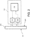
- a system for monitoring a brake disc in a braking system of a vehicle will now be described with reference to figures 1-2 .
- the system for monitoring a brake disc of a braking system of a vehicle hereinafter also simply monitoring system or system, is indicated as a whole in figures 1 and 2 by a dashed rectangle and reference numeral 100.
- a brake disc 200 which can be monitored by the monitoring system 100 is diagrammatically shown in figures 1 and 2 .
- FIG 1 the brake disc 200 is shown with a front view, while a side view is shown in figure 2 .
- the brake disc 200 is part of a braking system of a vehicle (not shown in the figures).
- the monitoring system 100 is installed in the braking system of the vehicle or in general on the vehicle itself, as will be described also hereinafter.
- the monitoring system 100 may be considered fixed, while the brake disc 200 is in rotation during normal use of the vehicle.
- the brake disc 200 though intended for a braking system of a vehicle, may be part of a test or service bench.
- the monitoring system 100 is installed on the test or service bench.
- the brake disc 200 is fixed, while the monitoring system 100, or at least part of it, rotates with respect to the brake disc 200.
- the brake disc 200 is moving, while the monitoring system 100, or at least part of it, is fixed with respect to the brake disc 200.
- the brake disc 200 is fixed while the monitoring system 100, or at least part of it, is moving with respect to the brake disc 200, tracing a set path.
- the system 100 comprises at least one source 101 of an electromagnetic quantity.
- the electromagnetic quantity is symbolically represented by an arrow facing from the source 101 towards the brake disc 200 and indicated by reference numeral s1.
- the electromagnetic quantity has a set space-time pattern such as to interact with the brake disc 200 in a manner dependent on the properties of the brake disc 200, generating a respective variable signal.
- the electromagnetic quantity s1 is a field defined in a space region containing the brake disc 200.
- variable signal s2 which can be generated by the interaction of the electromagnetic quantity with the brake disc 200 has a time pattern which may deviate from a set reference time pattern if an anomaly is present in the brake disc 200, e.g. a crack, a fissure, brake disc wear, brake disc deformation, and so on.
- the deviation of the time pattern of the variable signal s2 may occur in amplitude and/or in frequency and/or in phase.
- variable signal will also be described below.
- the electromagnetic quantity s1 may be an electrical field.
- the source 101 is an electrical field generator, e.g. a rechargeable plate, an emitter (antenna), a generator of alternating electrical current or of electrical charge.
- an electrical field generator e.g. a rechargeable plate, an emitter (antenna), a generator of alternating electrical current or of electrical charge.
- the electromagnetic quantity s1 may be a magnetic field.
- the source 101 is a magnetic field generator, e.g. a coil which can be energised, an electromagnet/magnet, a direct electrical current generator, alternating electrical current.
- a magnetic field generator e.g. a coil which can be energised, an electromagnet/magnet, a direct electrical current generator, alternating electrical current.
- the electromagnetic quantity s1 may be an electromagnetic field.
- the source 101 is an electromagnetic field generator, e.g. a coil which can be energised, an electromagnet, an emitter (antenna), a direct electrical current generator, alternating electrical current.
- an electromagnetic field generator e.g. a coil which can be energised, an electromagnet, an emitter (antenna), a direct electrical current generator, alternating electrical current.
- the system 100 further comprises at least one sensor 102 for detecting such variable signal.
- the source 101 and the at least one sensor 102 are mutually distinct.
- the source 101 and said at least one sensor 102 may coincide.
- variable signal s2 can be generated as a result of the interaction of the electromagnetic quantity s1 with the brake disc 200 in a manner dependent on the properties of the brake disc 200.
- variable signal s2 is the electromagnetic or electric or magnetic field resulting from the interaction of the electromagnetic quantity s1 with the brake disc 200.
- variable signal is indeed symbolically represented by an arrow facing from the brake disc 200 towards the detection sensor 102 and is indicated by reference numeral s2.
- such at least one detection sensor 102 faces towards a set limited portion of an investigation surface 201 of the brake disc 200.
- the set limited portion of the investigation surface 201 of the brake disc 200 is at least one set closed path c1 which can be defined on the investigation surface 201 of the brake disc 200.
- the set limited portion of an investigation surface 201 is at least one circumference c1 which can be defined on the investigation surface 201 of the brake disc 200.
- the at least one circumference c1 has a set first radius R1 with respect to the centre of the brake disc 200.
- the length of the first radius R1 is such that the detection sensor 102 is positioned at the outer part of the braking band of the brake disc 200, usually the most critical position for the formation of anomalies, such as cracks or fissures.
- the set portion of the investigation surface 201 comprises one or more set closed paths.
- the set portion of the investigation surface 201 comprises a further set closed path c2 definable on the investigation surface 201 of the brake disc 200 in addition to the at least one set closed path c1.
- the further set closed path c2 is a further circumference c2 which can be defined on the investigation surface 201 of the brake disc 200.
- the at least one circumference c1 and the further circumference c2 have set radii with respect to the centre of the brake disc.
- the further circumference c2 has a set second radius R2 with respect to the centre of the brake disc 200.
- the length of the set second radius R2 is smaller than the set first radius R1.
- the set limited portion of the investigation surface 201 of the brake disc comprises multiple set closed paths (e.g. circumferences) which can be defined on the investigation surface 201 of the brake disc 200 advantageously allows to increase the limited portion of investigation, which may cover most of the braking band of the brake disc 200, consequently improving the reliability of the monitoring system 100.
- the possibility of the set limited portion of the investigation surface 201 of brake disc 200 comprising at least one set closed path c1 (e.g. a circumference) or one or more further set closed paths c2 (e.g. circumferences) which can be defined on the investigation surface 201 of the brake disc 200 depends on the configuration of the detection sensor 102 used.
- the detection sensor 102 may be configured to perform a punctiform type reading (embodiment in figure 8 (a)). Such a configuration can be obtained by using a type of reading head with punctiform measuring area.
- the detection sensor 102 may be configured to perform a diffused type reading, wherein the width of the measuring area may be increased.
- the set limited portion of the investigation surface 201 of the brake disc 200 comprises at least one set closed path c1, such as a circumference or circumferential band or circular crown c1, which can be defined on the investigation surface 201 of the brake disc 200.
- the detection sensor 102 may be configured to perform a linear diffused reading. Such a configuration can be obtained by using a type of reading head with an elongated measuring area.
- the set limited portion of the investigation surface 201 of the brake disc 200 comprises at least one set closed path c1, such as a circumferential band or circular crown, which can be defined on the investigation surface 201 of the brake disc 200.
- the detection sensor 102 may be configured to perform multiple and/or matrix readings.
- the detection sensor 102 comprises a plurality of punctiform detection points distributed in a matrix. This configuration can be obtained by using multiple reading heads with punctiform measuring area.
- the set limited portion of the investigation surface 201 of the brake disc 200 comprises, as set closed paths, the at least one circumference c1 and the further circumference c2 which can be defined on the investigation surface 201 of the brake disc 200.
- the set limited portion of the investigation surface 201 of the brake disc 200 comprises, as set closed path, only at least one circumference c1 which can be defined on the investigation surface 201 of the brake disc.
- the detection points of the sensor 102 may also be distributed in the radial direction and transversally to the radial direction of the investigation surface 201 of the brake disc 200.
- the set limited portion of the investigation surface 201 of the brake disc 200 comprises the at least one set closed path c1 (e.g. a circumference c1) and the further set closed path c2 (e.g. a further circumference c2) which can be defined on the investigation surface 201 of the brake disc 200 and two detection points of the detection sensor 102 are present on one of the two (the at least one circumference c1 in figure 6 ).
- the detection sensor 102 may be configured to translate, e.g. by means of an actuating device (not shown in the figures) with which the system 100 may be provided, along the radial direction of the investigation surface 201 of the brake disc 200.
- the set limited portion of the investigation surface 201 of the brake disc 200 comprises a closed set path, the distance of which from the centre of the brake disc 200 is variable during the relative rotation between the brake disc 200 and the monitoring system 100.
- the system 100 may comprise a position sensor operatively coupled to said at least one detection sensor 102 in order to obtain more reliable measurements.
- the presence of one or more detection sensors or of one or more detection points advantageously allows to improve and increase the quantity of available information.
- the redundancy of such information allows to examine different positions in which the anomalies appear (cracks or fissures).
- the presence of multiple detection points on the circumference or closed path of the investigation surface 201 of the brake disc 200 itself allows to improve the robustness of the detections and possibly to be able to perform differential calculations on other quantities which can be monitored on the brake disc 200, such as for example the immediate calculation of the rotation speed or the different calculation of the brake disc wear.
- similar distributions could be obtained using a plurality of sensors, entirely similar to sensor 102 described above, each of which is provided with a detection point or, in turn, with one or more detection points according to any one of the configurations described above.
- the system 100 may comprise at least one detection sensor facing towards the set limited portion of the investigation surface 201 of the brake disc 200, as the detection sensor 102 described above, and at least one further detection sensor 102' (not shown for example in the figures) facing towards a set limited portion of a further investigation surface 201' of the brake disc, opposite to the investigation surface 201 ( figure 2 ).
- the at least one further detection sensor 102' may be made according to the different embodiments described above with reference to said at least one detection sensor 102, thus not repeated here.
- the at least one sensor 102 may be an integral part of a test or service bench using fixed or portable equipment, pen with sensor integrated inside.
- investigation surface of the brake disc 200 could be the outer surface of the brake disc or the fixing bell of the brake disc 200 (both not shown in figures).
- variable signal s2 can be advantageously analysed to determine at least one parameter of the brake disc 200 on the basis of a deviation of the time pattern of the variable signal detected by the at least one detection sensor 102 with respect to a set reference time pattern.
- the parameter of the brake disc 200 is representative of an anomaly of the brake disc 200.
- variable signal s2 is an electric field either reflected or modified by the interaction of the electromagnetic quantity s1 with the brake disc 200.
- the electromagnetic quantity s1 which can be generated by the source 101 is an electrical field.
- variable signal s2 is a magnetic field flux either reflected or modified by the interaction of the electromagnetic quantity s1 with the brake disc 200.
- the electromagnetic quantity s1 which can be generated by the source 101 is a magnetic field.
- variable signal s2 is an electromagnetic quantity either reflected or modified by the interaction of the electromagnetic quantity s1 with the brake disc 200.
- the electromagnetic quantity s1 which can be generated by the source 101 is an electromagnetic field.
- variable signal s2 is an eddy electric current generated by the brake disc 200 following the interaction with the brake disc 200 of the electromagnetic quantity s1 which can be generated by the source 101.
- the electromagnetic quantity s1 is a variable external magnetic field (alternating electrical current).
- the technology of the detection sensor 102 which can be used depends on the type of variable signal generated by the brake disc, thus the type of source 101 of electromagnetic quantity used in the monitoring system 100, both if the source 101 and the at least one sensor 102 are mutually distant and if the source 101 and the at least one sensor 102 coincide.
- the system 100 further comprises a data processing unit 103 operatively connected to the detection sensor 102.
- the data processing unit 103 is operatively connected to the detection sensor 102 by wire.
- the data processing unit 103 is operatively connected to the detection sensor 102 in wireless mode.
- the data processing unit 103 is advantageously configured to analyse the detected variable signal s2 and to determine at least one parameter of the brake disc 200 on the basis of a deviation of the time pattern of the variable signal s2 detected with respect to the set reference time pattern of the variable signal s2.
- the deviation of the time pattern of the variable signal s2 may occur in frequency and/or in amplitude and/or in phase.
- parameter of the brake disc 200 is representative of an anomaly of the brake disc 200.
- the data processing unit 103 is configured to generate the electromagnetic quantity s1 by actuating the generator 101 of the electromagnetic quantity s1.
- the data processing unit 103 is operatively connected, e.g. by means of a wire or in wireless mode, to the generator 101.
- the data processing unit 103 is further configured to receive the variable signal s2 detected by the detection sensor 102.
- the data processing unit 103 is further configured to filter the variable signal s2 detected by the detection sensor 102 by using a set filtering method.
- Examples of reliable filtering methods which can be used by the data processing unit 103 are filtering with wavelet transform, filtering with Fast Fourier Transform FFT or band-pass filtering (e.g. with a Butterworth filter, a Bessel filter and so on), either digital or analogue.
- the data processing unit 103 is further configured to compare the detected and filtered variable signal s2 with at least one reference threshold value.
- the data processing unit 103 is further configured to provide information representative of the presence of a parameter of the brake disc 200 on the basis of the comparison of the detected variable signal s2 filtered with said at least one reference threshold value.
- the data processing unit 103 is configured to provide said information representative of the presence of an anomaly of the brake disc 200.
- the data processing unit 103 is configured to not provide said information representative of the presence of an anomaly of the brake disc 200.
- variable signal s2 detected by the detection sensor 102 allows to provide information representative of the presence of a socalled direct anomaly of the brake disc 200, i.e. a crack, a fissure, wear or a deformation of the brake disc 200.
- the data processing unit 103 is configured to determine first information representative of the use of the brake disc 200 on the basis of the variable signal s2 detected by the sensor 102.
- Such first information representative of the use of the brake disc 200 comprises structural or functional parameters of the brake disc 200, such as rotation speed, braking intensity, residual torque, locked brake disc condition, temperature, presence of water, presence of rust, consumption of material of a carbon-based brake disc (carbon-ceramic, CCM, carbo-carco, CC), and so-on.
- structural or functional parameters of the brake disc 200 such as rotation speed, braking intensity, residual torque, locked brake disc condition, temperature, presence of water, presence of rust, consumption of material of a carbon-based brake disc (carbon-ceramic, CCM, carbo-carco, CC), and so-on.
- the data processing unit 103 is configured to determine the rotation speed of the brake disc 200 either on the basis of the periodicity of the detected variable signal s2 or on the basis of the time difference between variable signals detected by two different detection points (if present) of the sensor 102 or by two different detection sensors placed on the same circumference c1 which can be defined on the investigation surface of the brake disc 200.
- the data processing unit 103 is configured to determine second information representative of the use of the brake disc 200 on the basis of the first information representative of the use of the brake disc 200.
- the second information representative of the use of the brake disc 200 comprise structural or functional parameters of the brake disc or of the vehicle in general, i.e. information which is more complicated to be determined with respect to the first information representative of the use of the brake disc 200, such as for example an assessment of the vehicle grip on the road, the friction between brake disc and brake pad, and so on.
- the data processing unit 103 is an electronic control unit integrated in the braking system of the vehicle.
- the data processing unit 103 is a main electronic control unit of the vehicle.
- the main electronic control unit of the vehicle is configured with specific program codes the running of which allows to perform the operations described above with reference to the data processing unit 103.
- the data processing unit 103 is an electronic test or service bench.
- the electronic processor of the test or service bench is configured with specific program codes the running of which allows to perform the operations described above with reference to the main electronic data processing unit 103 of the vehicle.
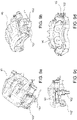
- said at least one detection sensor 102 may be housed in a respective housing defined in a bracket of a floating body 90 for brake disc.
- the monitoring system 100 further comprises at least one detection sensor 102'.
- the at least one detection sensor 102 and the at least one further detection sensor 102' are arranged so as to face towards a respective investigation surface of the brake disc (not shown in figures 9a-9d ).
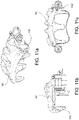
- said at least one detection sensor 102 may be housed in a respective housing defined in a fixed calliper body 91 for brake disc.
- the monitoring system 100 further comprises at least one detection sensor 102'.
- the at least one detection sensor 102 and the at least one further detection sensor 102' are arranged so as to face towards a respective investigation surface of the brake disc (not shown in figures 10a-10c ).
- said at least one detection sensor 102 may be housed in a respective housing defined in a floating calliper body 92 for brake disc.
- the at least one detection sensor 102 is arranged so as to be towards a respective investigation surface of the brake disc (not shown in figures 11a-11c ).
- the at least one detection sensor 102 is installed on non-rotating components of the vehicle near the brake disc, such as, for example, a stub axle, a suspension or a chassis of the vehicle.
- a brake disc can be monitored by determining a parameter of the brake disc and consequently the presence of cracks or fissures and other information representative of the use of the brake disc, thus of the braking system in general, by means of detection sensors which exploit the eddy currents and/or the magnetic field and/or the electrical field.
- the detection may be performed instantaneously and the position of the anomaly (crack) may be identified in addition to its presence.
- the sensors which can be used are simple, cost-effective and easy to integrate.
- the processing algorithms (filtering, comparing, and so on) of the information are simple and do not require high calculation resources, the technology and the reading are robust with respect to difficult environmental conditions, such as temperature, humidity, dirt, water and so on.
- the detection sensor is compact and may be easily integrated.
- monitoring system of braking system of a vehicle may be used to monitor other components of the braking system, either additionally or alternatively to the brake disc, such as callipers or pads, or to monitor other vehicle components, such as stub axle, chassis, suspension, bearing and so on.
Landscapes
- Engineering & Computer Science (AREA)
- General Engineering & Computer Science (AREA)
- Mechanical Engineering (AREA)
- Transportation (AREA)
- Braking Arrangements (AREA)
Description
- The present invention relates to a system for monitoring a brake disc of a braking system of a vehicle.
- Nowadays, in order to improve the monitoring of a brake disc, in addition to measuring the wear of the brake disc itself, the need is increasingly felt to be able to monitor the presence of anomalies due to wear, e.g. deformations, which could be formed on the brake disc before the end of its working life putting at risk the reliability of the braking system of the vehicle itself, and thus the safety of the vehicle itself.
- With this regard, there are monitoring systems of a brake disc of a vehicle adapted to directly detect an anomaly on the surface of a brake disc.
- However, such monitoring systems require the arrangement of specific components in close proximity to the surface of the brake disc which certainly represents a limit from the point of view of the installation of such monitoring system in the braking system.
- Furthermore, the very close distance to the surface of the brake disc could damage both the brake disc and the monitoring system during operation of the vehicle.
- Additionally, in some cases, the measuring quality of the anomaly may be compromised in presence of dust, water and dirt in general. In yet other cases, it would not be possible to detect specific anomalies, such as cracks and fissures present on the surface of the brake disc.
EP 2182347A2 describes state of the art a disc wear sensor placed on the disc itself. - It is the object of the present invention to devise and provide a system for monitoring a brake disc of a braking system of a vehicle which allows to avoid, at least partially, the drawbacks described above with reference to the prior art and which ensures a reliable and timely detection of a brake disc anomaly, also in presence of cracks or fissures.
- Such an object is achieved by means of a monitoring system according to
claim 1. - Preferred embodiments of such monitoring system are defined in the dependent claims.
- Further features and advantages of the system for monitoring a brake disc of a braking system of a vehicle according to the invention will be apparent in the following description which illustrates preferred embodiments, given by way of indicative, non-limiting examples, with reference to the accompanying figures, in which:
-
figure 1 diagrammatically shows a front view of a brake disc and a system for monitoring a brake disc of a braking system of a vehicle, according to an embodiment of the invention; -
figure 2 diagrammatically shows a side view of a brake disc and a system for monitoring a brake disc of a braking system of a vehicle offigure 1 ; -
figures 3, 4, 5 and 6 diagrammatically show a brake disc and one or more components of a system for monitoring a brake disc of a braking system of a vehicle, according to different embodiments of the invention; -
figure 7 diagrammatically shows a brake disc, a brake calliper for a brake disc and a component of a system for monitoring a braking system of a vehicle according to a further embodiment of the invention; -
figure 8 diagrammatically shows a component of a system for monitoring a brake disc of a braking system of a vehicle according to different embodiments; -
figures 9a-9d show different views of an example of a calliper body for brake disc with which one or more components of a system for monitoring a braking system of a vehicle are associated according to an embodiment of the invention; -
figures 10a-10c show different views of a further example of a calliper body for brake disc with which one or more components of a system for monitoring a braking system of a vehicle are associated according to a further embodiment of the invention, and -
figures 11a-11c show different views of a further example of a calliper body for brake disc with which one or more components of a monitoring system of a braking system of a vehicle are associated according to a further embodiment of the invention. - A system for monitoring a brake disc in a braking system of a vehicle, according to an embodiment of the present invention, will now be described with reference to
figures 1-2 . - It is worth noting that equal or similar elements in the figures will be indicated by the same reference numerals.
- The system for monitoring a brake disc of a braking system of a vehicle, hereinafter also simply monitoring system or system, is indicated as a whole in
figures 1 and2 by a dashed rectangle andreference numeral 100. - A
brake disc 200 which can be monitored by themonitoring system 100 is diagrammatically shown infigures 1 and2 . - In greater detail, in
figure 1 thebrake disc 200 is shown with a front view, while a side view is shown infigure 2 . - In an embodiment, the
brake disc 200 is part of a braking system of a vehicle (not shown in the figures). - In this embodiment, the
monitoring system 100 is installed in the braking system of the vehicle or in general on the vehicle itself, as will be described also hereinafter. - In this embodiment, the
monitoring system 100 may be considered fixed, while thebrake disc 200 is in rotation during normal use of the vehicle. - In a further embodiment, alternative to the one above, the
brake disc 200, though intended for a braking system of a vehicle, may be part of a test or service bench. - In this embodiment, the
monitoring system 100 is installed on the test or service bench. - In this embodiment, the
brake disc 200 is fixed, while themonitoring system 100, or at least part of it, rotates with respect to thebrake disc 200. - In another embodiment, alternative to the one above, although the monitoring system is installed on a test or service bench, the
brake disc 200 is moving, while themonitoring system 100, or at least part of it, is fixed with respect to thebrake disc 200. - In another embodiment, alternative to the one above, although the monitoring system is installed on a test or service bench, the
brake disc 200 is fixed while themonitoring system 100, or at least part of it, is moving with respect to thebrake disc 200, tracing a set path. - Again, with reference to the embodiment in
figures 1 and2 , thesystem 100 comprises at least onesource 101 of an electromagnetic quantity. - In
figure 2 , the electromagnetic quantity is symbolically represented by an arrow facing from thesource 101 towards thebrake disc 200 and indicated by reference numeral s1. - The electromagnetic quantity has a set space-time pattern such as to interact with the
brake disc 200 in a manner dependent on the properties of thebrake disc 200, generating a respective variable signal. - In other words, the electromagnetic quantity s1 is a field defined in a space region containing the
brake disc 200. - The variable signal s2 which can be generated by the interaction of the electromagnetic quantity with the
brake disc 200 has a time pattern which may deviate from a set reference time pattern if an anomaly is present in thebrake disc 200, e.g. a crack, a fissure, brake disc wear, brake disc deformation, and so on. - It is worth noting that the deviation of the time pattern of the variable signal s2 may occur in amplitude and/or in frequency and/or in phase.
- It is worth noting that the variable signal will also be described below.
- According to an embodiment, the electromagnetic quantity s1 may be an electrical field.
- In such embodiment, the
source 101 is an electrical field generator, e.g. a rechargeable plate, an emitter (antenna), a generator of alternating electrical current or of electrical charge. - According to a further embodiment, alternative to the one above, the electromagnetic quantity s1 may be a magnetic field.
- In such embodiment, the
source 101 is a magnetic field generator, e.g. a coil which can be energised, an electromagnet/magnet, a direct electrical current generator, alternating electrical current. - According to a further embodiment, alternative to the ones above, the electromagnetic quantity s1 may be an electromagnetic field.
- In such embodiment, the
source 101 is an electromagnetic field generator, e.g. a coil which can be energised, an electromagnet, an emitter (antenna), a direct electrical current generator, alternating electrical current. - Turning in general to the embodiment shown in
figures 1 and2 , thesystem 100 further comprises at least onesensor 102 for detecting such variable signal. - According to an embodiment, symbolically shown in
figures 1 and2 , thesource 101 and the at least onesensor 102 are mutually distinct. - According to a further embodiment, alternative to the one described above, the
source 101 and said at least onesensor 102 may coincide. - As mentioned above, the variable signal s2 can be generated as a result of the interaction of the electromagnetic quantity s1 with the
brake disc 200 in a manner dependent on the properties of thebrake disc 200. - It is worth noting that in an embodiment, the variable signal s2 is the electromagnetic or electric or magnetic field resulting from the interaction of the electromagnetic quantity s1 with the
brake disc 200. - This can be obtained by modifying the electrical and/or magnetic quantities of the
source 101 as a consequence perturbing the respective energising signal and generating an internal feedback which can be detected by current and/or voltage reading. - With this regard, in
figure 2 , the variable signal is indeed symbolically represented by an arrow facing from thebrake disc 200 towards thedetection sensor 102 and is indicated by reference numeral s2. - Advantageously, such at least one
detection sensor 102 faces towards a set limited portion of aninvestigation surface 201 of thebrake disc 200. - The set limited portion of the
investigation surface 201 of thebrake disc 200 is at least one set closed path c1 which can be defined on theinvestigation surface 201 of thebrake disc 200. - According to an embodiment, also shown in
figures 3-7 , the set limited portion of aninvestigation surface 201 is at least one circumference c1 which can be defined on theinvestigation surface 201 of thebrake disc 200. - In this embodiment, shown in
figures 3-7 , the at least one circumference c1 has a set first radius R1 with respect to the centre of thebrake disc 200. - It is worth noting that in this embodiment, the simplest, the length of the first radius R1 is such that the
detection sensor 102 is positioned at the outer part of the braking band of thebrake disc 200, usually the most critical position for the formation of anomalies, such as cracks or fissures. - According to further embodiments, the set portion of the
investigation surface 201 comprises one or more set closed paths. - In particular, the set portion of the
investigation surface 201 comprises a further set closed path c2 definable on theinvestigation surface 201 of thebrake disc 200 in addition to the at least one set closed path c1. - In the embodiments of the
figure 4 and 6 , the further set closed path c2 is a further circumference c2 which can be defined on theinvestigation surface 201 of thebrake disc 200. - The at least one circumference c1 and the further circumference c2 have set radii with respect to the centre of the brake disc.
- In particular, the further circumference c2 has a set second radius R2 with respect to the centre of the
brake disc 200. - In such embodiments, the length of the set second radius R2 is smaller than the set first radius R1.
- It is worth noting that the fact that the set limited portion of the
investigation surface 201 of the brake disc comprises multiple set closed paths (e.g. circumferences) which can be defined on theinvestigation surface 201 of thebrake disc 200 advantageously allows to increase the limited portion of investigation, which may cover most of the braking band of thebrake disc 200, consequently improving the reliability of themonitoring system 100. - With this regard, it is worth noting that the possibility of the set limited portion of the
investigation surface 201 ofbrake disc 200 comprising at least one set closed path c1 (e.g. a circumference) or one or more further set closed paths c2 (e.g. circumferences) which can be defined on theinvestigation surface 201 of thebrake disc 200 depends on the configuration of thedetection sensor 102 used. - With reference also to
figure 8 , in an embodiment, thedetection sensor 102 may be configured to perform a punctiform type reading (embodiment in figure 8 (a)). Such a configuration can be obtained by using a type of reading head with punctiform measuring area. - In a further embodiment, shown in figure 8(b), the
detection sensor 102 may be configured to perform a diffused type reading, wherein the width of the measuring area may be increased. - According to this embodiment, the set limited portion of the
investigation surface 201 of thebrake disc 200 comprises at least one set closed path c1, such as a circumference or circumferential band or circular crown c1, which can be defined on theinvestigation surface 201 of thebrake disc 200. - According to a further embodiment, shown in figure 8 (c), the
detection sensor 102 may be configured to perform a linear diffused reading. Such a configuration can be obtained by using a type of reading head with an elongated measuring area. - According to this embodiment, the set limited portion of the
investigation surface 201 of thebrake disc 200 comprises at least one set closed path c1, such as a circumferential band or circular crown, which can be defined on theinvestigation surface 201 of thebrake disc 200. - According to further embodiments, shown in figures 8 (d) and 8 (e), the
detection sensor 102 may be configured to perform multiple and/or matrix readings. - In particular, in these embodiments, the
detection sensor 102 comprises a plurality of punctiform detection points distributed in a matrix. This configuration can be obtained by using multiple reading heads with punctiform measuring area. - If the detection points are distributed on a same line along the radial direction of the
investigation surface 201 of thebrake disc 200, as shown infigure 8 (d) and in the embodiment offigure 4 , the set limited portion of theinvestigation surface 201 of thebrake disc 200 comprises, as set closed paths, the at least one circumference c1 and the further circumference c2 which can be defined on theinvestigation surface 201 of thebrake disc 200. - If the detection points are distributed on a same line transversally to the radial direction of the
investigation surface 201 of thebrake disc 200, as shown in figure 8 (e) and in the embodiment offigure 5 , the set limited portion of theinvestigation surface 201 of thebrake disc 200 comprises, as set closed path, only at least one circumference c1 which can be defined on theinvestigation surface 201 of the brake disc. - According to a further embodiment, shown in
figure 6 , the detection points of thesensor 102 may also be distributed in the radial direction and transversally to the radial direction of theinvestigation surface 201 of thebrake disc 200. - In the case of
figure 6 , the set limited portion of theinvestigation surface 201 of thebrake disc 200 comprises the at least one set closed path c1 (e.g. a circumference c1) and the further set closed path c2 (e.g. a further circumference c2) which can be defined on theinvestigation surface 201 of thebrake disc 200 and two detection points of thedetection sensor 102 are present on one of the two (the at least one circumference c1 infigure 6 ). - It is worth noting that in order to be able to monitor most of the braking band of the
brake disc 200, alternatively to the use of adetection sensor 102 provided with a plurality of detection points distributed in the radial direction of theinvestigation surface 201 of the brake disc, in a further embodiment, thedetection sensor 102 may be configured to translate, e.g. by means of an actuating device (not shown in the figures) with which thesystem 100 may be provided, along the radial direction of theinvestigation surface 201 of thebrake disc 200. - In this embodiment, the set limited portion of the
investigation surface 201 of thebrake disc 200 comprises a closed set path, the distance of which from the centre of thebrake disc 200 is variable during the relative rotation between thebrake disc 200 and themonitoring system 100. - According to a further embodiment, in combination with any one of those described above, the
system 100 may comprise a position sensor operatively coupled to said at least onedetection sensor 102 in order to obtain more reliable measurements. - It is worth noting that the presence of one or more detection sensors or of one or more detection points (within the same sensor) advantageously allows to improve and increase the quantity of available information. The redundancy of such information allows to examine different positions in which the anomalies appear (cracks or fissures).
- With reference again to the embodiments in
figures 4, 5 and 6 , it is worth noting that the presence of one or more detection points distributed on multiple circumferences or anyway on multiple closed paths with different radii of theinvestigation surface 201 of the brake disc allows to monitor most of the braking band. - Instead, the presence of multiple detection points on the circumference or closed path of the
investigation surface 201 of thebrake disc 200 itself allows to improve the robustness of the detections and possibly to be able to perform differential calculations on other quantities which can be monitored on thebrake disc 200, such as for example the immediate calculation of the rotation speed or the different calculation of the brake disc wear. - With this regard, it is worth noting that the embodiments described hereto make reference to the presence of at least one
detection sensor 102 in which one or more detection points (detection heads) are envisaged, distributed according to any one of the configurations described above. - Alternatively or in combination with this embodiment, similar distributions could be obtained using a plurality of sensors, entirely similar to
sensor 102 described above, each of which is provided with a detection point or, in turn, with one or more detection points according to any one of the configurations described above. - Furthermore, alternatively or in combination with the embodiments described above, the
system 100, according to an embodiment, may comprise at least one detection sensor facing towards the set limited portion of theinvestigation surface 201 of thebrake disc 200, as thedetection sensor 102 described above, and at least one further detection sensor 102' (not shown for example in the figures) facing towards a set limited portion of a further investigation surface 201' of the brake disc, opposite to the investigation surface 201 (figure 2 ). - The at least one further detection sensor 102' may be made according to the different embodiments described above with reference to said at least one
detection sensor 102, thus not repeated here. - According to a further embodiment, the at least one
sensor 102 may be an integral part of a test or service bench using fixed or portable equipment, pen with sensor integrated inside. - According to further embodiments, it is worth noting that the investigation surface of the
brake disc 200 could be the outer surface of the brake disc or the fixing bell of the brake disc 200 (both not shown in figures). - Turning now in general to the
monitoring system 100 infigures 1 and2 , it is worth noting that the variable signal s2 can be advantageously analysed to determine at least one parameter of thebrake disc 200 on the basis of a deviation of the time pattern of the variable signal detected by the at least onedetection sensor 102 with respect to a set reference time pattern. - According to an embodiment, the parameter of the
brake disc 200 is representative of an anomaly of thebrake disc 200. - Turning back to the variable signal s2, according to an embodiment, it is an electric field either reflected or modified by the interaction of the electromagnetic quantity s1 with the
brake disc 200. - In this embodiment, the electromagnetic quantity s1 which can be generated by the
source 101 is an electrical field. - According to a further embodiment, alternative to the one above, the variable signal s2 is a magnetic field flux either reflected or modified by the interaction of the electromagnetic quantity s1 with the
brake disc 200. - In this embodiment, the electromagnetic quantity s1 which can be generated by the
source 101 is a magnetic field. - According to a further embodiment, alternative to the ones above, the variable signal s2 is an electromagnetic quantity either reflected or modified by the interaction of the electromagnetic quantity s1 with the
brake disc 200. - In this embodiment, the electromagnetic quantity s1 which can be generated by the
source 101 is an electromagnetic field. - According to a further embodiment, alternative to the ones above, the variable signal s2 is an eddy electric current generated by the
brake disc 200 following the interaction with thebrake disc 200 of the electromagnetic quantity s1 which can be generated by thesource 101. In this embodiment, the electromagnetic quantity s1 is a variable external magnetic field (alternating electrical current). - The technology of the
detection sensor 102 which can be used depends on the type of variable signal generated by the brake disc, thus the type ofsource 101 of electromagnetic quantity used in themonitoring system 100, both if thesource 101 and the at least onesensor 102 are mutually distant and if thesource 101 and the at least onesensor 102 coincide. - Turning back to the embodiment in
figures 1 and2 , thesystem 100 further comprises adata processing unit 103 operatively connected to thedetection sensor 102. - In an embodiment, the
data processing unit 103 is operatively connected to thedetection sensor 102 by wire. - In an embodiment alternative to the one above, the
data processing unit 103 is operatively connected to thedetection sensor 102 in wireless mode. - The
data processing unit 103 is advantageously configured to analyse the detected variable signal s2 and to determine at least one parameter of thebrake disc 200 on the basis of a deviation of the time pattern of the variable signal s2 detected with respect to the set reference time pattern of the variable signal s2. - It is worth noting that the deviation of the time pattern of the variable signal s2 may occur in frequency and/or in amplitude and/or in phase.
- It is also worth noting that the parameter of the
brake disc 200 is representative of an anomaly of thebrake disc 200. - In greater detail, the
data processing unit 103 is configured to generate the electromagnetic quantity s1 by actuating thegenerator 101 of the electromagnetic quantity s1. With this regard, thedata processing unit 103 is operatively connected, e.g. by means of a wire or in wireless mode, to thegenerator 101. - The
data processing unit 103 is further configured to receive the variable signal s2 detected by thedetection sensor 102. - The
data processing unit 103 is further configured to filter the variable signal s2 detected by thedetection sensor 102 by using a set filtering method. - Examples of reliable filtering methods which can be used by the
data processing unit 103 are filtering with wavelet transform, filtering with Fast Fourier Transform FFT or band-pass filtering (e.g. with a Butterworth filter, a Bessel filter and so on), either digital or analogue. - The
data processing unit 103 is further configured to compare the detected and filtered variable signal s2 with at least one reference threshold value. - The
data processing unit 103 is further configured to provide information representative of the presence of a parameter of thebrake disc 200 on the basis of the comparison of the detected variable signal s2 filtered with said at least one reference threshold value. - In particular, if the detected and filtered variable signal s2 is over the reference threshold value, the
data processing unit 103 is configured to provide said information representative of the presence of an anomaly of thebrake disc 200. - If instead the detected and filtered variable signal s2 is under the reference threshold value, the
data processing unit 103 is configured to not provide said information representative of the presence of an anomaly of thebrake disc 200. - It is worth noting that the variable signal s2 detected by the
detection sensor 102 allows to provide information representative of the presence of a socalled direct anomaly of thebrake disc 200, i.e. a crack, a fissure, wear or a deformation of thebrake disc 200. - According to a further embodiment, the
data processing unit 103 is configured to determine first information representative of the use of thebrake disc 200 on the basis of the variable signal s2 detected by thesensor 102. - Such first information representative of the use of the
brake disc 200 comprises structural or functional parameters of thebrake disc 200, such as rotation speed, braking intensity, residual torque, locked brake disc condition, temperature, presence of water, presence of rust, consumption of material of a carbon-based brake disc (carbon-ceramic, CCM, carbo-carco, CC), and so-on. - In the case of speed, the
data processing unit 103 is configured to determine the rotation speed of thebrake disc 200 either on the basis of the periodicity of the detected variable signal s2 or on the basis of the time difference between variable signals detected by two different detection points (if present) of thesensor 102 or by two different detection sensors placed on the same circumference c1 which can be defined on the investigation surface of thebrake disc 200. - According to a further embodiment, the
data processing unit 103 is configured to determine second information representative of the use of thebrake disc 200 on the basis of the first information representative of the use of thebrake disc 200. - The second information representative of the use of the
brake disc 200 comprise structural or functional parameters of the brake disc or of the vehicle in general, i.e. information which is more complicated to be determined with respect to the first information representative of the use of thebrake disc 200, such as for example an assessment of the vehicle grip on the road, the friction between brake disc and brake pad, and so on. - Turning now back in general to the
monitoring system 100 of thefigures 1 and2 , according to an embodiment, thedata processing unit 103 is an electronic control unit integrated in the braking system of the vehicle. - According to a further embodiment, the
data processing unit 103 is a main electronic control unit of the vehicle. - In such a case, the main electronic control unit of the vehicle is configured with specific program codes the running of which allows to perform the operations described above with reference to the
data processing unit 103. - According to a further embodiment, the
data processing unit 103 is an electronic test or service bench. - Also in this case, the electronic processor of the test or service bench is configured with specific program codes the running of which allows to perform the operations described above with reference to the main electronic
data processing unit 103 of the vehicle. - Some possible arrangements of said at least one
sensor 102 of themonitoring system 100 when integrated in a braking system of a vehicle are described with reference now also tofigures 9a-9d ,10a-10c and11a-11c . - In an embodiment (
figures 9a-9d ), said at least onedetection sensor 102 may be housed in a respective housing defined in a bracket of a floatingbody 90 for brake disc. - It is worth noting that in the embodiment of
figures 9a-9d themonitoring system 100 further comprises at least one detection sensor 102'. - The at least one
detection sensor 102 and the at least one further detection sensor 102' are arranged so as to face towards a respective investigation surface of the brake disc (not shown infigures 9a-9d ). - In a further embodiment (
figures 10a-10c ), said at least onedetection sensor 102 may be housed in a respective housing defined in a fixedcalliper body 91 for brake disc. - It is worth noting that in the embodiment of
figures 10a-10c themonitoring system 100 further comprises at least one detection sensor 102'. - The at least one
detection sensor 102 and the at least one further detection sensor 102' are arranged so as to face towards a respective investigation surface of the brake disc (not shown infigures 10a-10c ). - In a further embodiment (
figures 11a-11c ), said at least onedetection sensor 102 may be housed in a respective housing defined in a floatingcalliper body 92 for brake disc. - The at least one
detection sensor 102 is arranged so as to be towards a respective investigation surface of the brake disc (not shown infigures 11a-11c ). - According to further embodiments, not shown in the figures and alternative to the ones described above, the at least one
detection sensor 102 is installed on non-rotating components of the vehicle near the brake disc, such as, for example, a stub axle, a suspension or a chassis of the vehicle. - As apparent, the object of the invention is achieved because the suggested monitoring system has many advantages.
- Firstly, a brake disc can be monitored by determining a parameter of the brake disc and consequently the presence of cracks or fissures and other information representative of the use of the brake disc, thus of the braking system in general, by means of detection sensors which exploit the eddy currents and/or the magnetic field and/or the electrical field.
- This allows to obtain contactless detections of anomalies, also allowing a multiple detection of different quantities which may contribute to the determination of different information.
- Furthermore, the detection may be performed instantaneously and the position of the anomaly (crack) may be identified in addition to its presence.
- Furthermore, the sensors which can be used are simple, cost-effective and easy to integrate.
- The processing algorithms (filtering, comparing, and so on) of the information are simple and do not require high calculation resources, the technology and the reading are robust with respect to difficult environmental conditions, such as temperature, humidity, dirt, water and so on.
- The detection sensor is compact and may be easily integrated.
- It is worth noting that the monitoring system of braking system of a vehicle may be used to monitor other components of the braking system, either additionally or alternatively to the brake disc, such as callipers or pads, or to monitor other vehicle components, such as stub axle, chassis, suspension, bearing and so on.
- A person skilled in art may make changes and adaptations to the embodiments of the aforesaid system for monitoring a brake disc of a braking system of a vehicle or can replace elements with others which are functionally equivalent to satisfy contingent needs without departing from the scope of protection of the appended claims
Claims (17)
- System (100) for monitoring a brake disc (200) of a braking system of a vehicle, comprising:- at least one source (101) of an electromagnetic quantity (s1) having a set space-time pattern such as to interact with the brake disc (200) in a manner dependent on the properties of the brake disc (200), generating a respective variable signal (s2);- at least one sensor (102) for detecting such variable signal (s2), said at least one detection sensor (102) facing a set limited portion of an investigation surface (201) of the brake disc (200), said set limited portion of the investigation surface (201) being at least one set closed path (c1, c2) that can be defined on the investigation surface (201) of the brake disc (200), the at least one detection sensor (102) being installed on non-rotating components of the vehicle near the brake disc (200);- the detected variable signal (s2) being able to be analysed to determine at least one parameter of the brake disc (200) based on a deviation of the time pattern of the detected variable signal (s2) with respect to a set reference time pattern.
- System (100) according to claim 1, wherein the electromagnetic quantity (s1) is a field defined in a space region containing the brake disc (200).
- System (100) according to any one of the preceding claims, wherein the electromagnetic quantity (s1) is at least one of: electric field, magnetic field, electromagnetic field, variable external electric field.
- System (100) according to any one of the preceding claims, wherein the variable signal (s2) is the electromagnetic or electric or magnetic field resulting from the interaction of the electromagnetic quantity (s1) with the brake disc (200).
- System (100) according to any one of the preceding claims, wherein the detected variable signal (s2) is at least one of: eddy electric current generated by the brake disc (200), or electric field reflected or modified by the interaction of the electromagnetic quantity (s1) with the brake disc (200), or magnetic flow reflected or modified by the interaction of the electromagnetic quantity (s1) with the brake disc (200), or electromagnetic field reflected or modified by the interaction of the electromagnetic quantity (s1) with the brake disc (200).
- System (100) according to any one of the preceding claims, wherein the set limited portion of the investigation surface (201) of the brake disc comprises a further set closed path (c2) that can be defined on the investigation surface (201) of the brake disc (200).
- System (100) according to any one of the preceding claims, wherein the detection sensor (102) is configured to perform a reading of punctual type, or of diffused type, or a reading of linear diffused type or a reading of matrix diffused type, said at least one detection sensor (102) being provided inside with one or more detection points distributed according to any one of such configurations.
- System (100) according to any one of the preceding claims, comprising a plurality of detection sensors, each of which is provided with a detection point or with one or more detection points.
- System (100) according to any one of the preceding claims, further comprising at least one further detection sensor (102') facing a set limited portion of a further investigation surface (201') of the brake disc (200), opposite the investigation surface (201).
- System (100) according to any one of the preceding claims, further comprising a data processing unit (103) operatively connected to said at least one detection sensor (102), the data processing unit (103) being configured to analyse the detected variable signal (s2) and to determine at least one parameter of the brake disc (200) based on a deviation of the time pattern of the variable signal (s2) with respect to the set reference time pattern of the variable signal (s2).
- System (100) according to claim 10, wherein the data processing unit (103) is configured to:- generate the electromagnetic quantity (s1) by actuating the generator (101) of the electromagnetic quantity (s1);- receive the variable signal (s2) detected by the detection sensor (102);- filter the variable signal (s2) detected by said at least one detection sensor (102) by using a set filtering method of the wavelet transform filtering, fast Fourier transform FFT filtering or band-pass filtering type;- compare the variable signal (s2) detected and filtered with at least one reference threshold value;- provide information representative of a parameter of the brake disc (200) based on the comparison of the variable signal (s2) detected and filtered with said at least one reference threshold value.
- System (100) according to any one of the preceding claims, wherein the parameter of the brake disc (200) is representative of an anomaly of the brake disc (200).
- System (100) according to claim 12, wherein the anomaly of the brake disc (200) is at least one crack, fissure, wear or deformation of the brake disc (200).
- System (100) according to any one of the preceding claims from 11 to 13, wherein the data processing unit (103) is configured to determine first information representative of the use of the brake disc (200) based on the variable signal (s2) detected by the sensor (102), or the speed of rotation, or the intensity of braking, or the residual torque, or the condition of blocked brake disc, or the temperature, or the presence of water, or the presence of rust, or the material wear of a carbon-based brake disc.
- System (100) according to claim 14, wherein the data processing unit (103) is configured to determine second information representative of the use of the brake disc (200) based on the first information representative of the use of the brake disc (200), that is at least evaluation of the vehicle grip on the road, friction between brake disc and brake pad.
- System (100) according to any one of the preceding claims from 10 to 15, wherein the data processing unit (103) is an electronic control unit integrated inside the brake system of the vehicle or a main electronic control unit of the vehicle or an electronic processor of a test or assistance bench.
- System (100) according to any one of the preceding claims, wherein the non-rotating components of the vehicle near the brake disc on which the at least one detection sensor (102) is installed belong to group comprising: a stub axle, a suspension or a chassis of the vehicle.
Applications Claiming Priority (2)
| Application Number | Priority Date | Filing Date | Title |
|---|---|---|---|
| ITUA2016A003189A ITUA20163189A1 (en) | 2016-05-05 | 2016-05-05 | Brake disc monitoring system of a vehicle's brake system |
| PCT/IB2017/052617 WO2017191601A1 (en) | 2016-05-05 | 2017-05-05 | System for monitoring a brake disc of a braking system of a vehicle |
Publications (2)
| Publication Number | Publication Date |
|---|---|
| EP3452348A1 EP3452348A1 (en) | 2019-03-13 |
| EP3452348B1 true EP3452348B1 (en) | 2022-06-29 |
Family
ID=56853737
Family Applications (1)
| Application Number | Title | Priority Date | Filing Date |
|---|---|---|---|
| EP17733008.1A Active EP3452348B1 (en) | 2016-05-05 | 2017-05-05 | System for monitoring a brake disc of a braking system of a vehicle |
Country Status (4)
| Country | Link |
|---|---|
| US (1) | US11167741B2 (en) |
| EP (1) | EP3452348B1 (en) |
| IT (1) | ITUA20163189A1 (en) |
| WO (1) | WO2017191601A1 (en) |
Families Citing this family (3)
| Publication number | Priority date | Publication date | Assignee | Title |
|---|---|---|---|---|
| EP3626565B1 (en) * | 2018-09-19 | 2023-04-26 | Goodrich Actuation Systems Limited | Brake plate wear detection using solenoid current signature |
| IT202200006797A1 (en) * | 2022-04-06 | 2023-10-06 | Itt Italia Srl | SYSTEM AND METHOD FOR CARRYING OUT ONLINE QUALITY TESTS ON BLOCKS OF FRICTION MATERIAL OF BRAKING ELEMENTS FOR VEHICLES, IN PARTICULAR BRAKE PADS |
| IT202300005877A1 (en) * | 2023-03-28 | 2024-09-28 | Brembo Spa | SYSTEM FOR DETECTING OPERATING STATUS CONDITIONS ASSOCIATED WITH A MOVING COMPONENT OF A VEHICLE BRAKING SYSTEM AND RELATED DETECTION METHODS |
Family Cites Families (14)
| Publication number | Priority date | Publication date | Assignee | Title |
|---|---|---|---|---|
| US4271393A (en) * | 1978-12-29 | 1981-06-02 | The Boeing Company | Apparatus and method for eddy current detection of subsurface discontinuities in conductive bodies |
| US5028100A (en) * | 1989-06-15 | 1991-07-02 | Trustees Of The Thomas A. D. Gross 1988 Revocable Trust | Methods for nondestructive eddy-current testing of structural members with automatic characterization of faults |
| US5811970A (en) * | 1996-05-10 | 1998-09-22 | Northrop Grumman Corporation | Electromagnetic test for microstructure anomalies such as alpha-case, and for carbide precipitates and untempered and overtempered martensite |
| US6285183B1 (en) * | 1996-09-30 | 2001-09-04 | Mcdonnell Douglas Corporation | Method and system for measuring the volume loss of a metal substrate |
| GB2329712B (en) * | 1997-09-27 | 2001-10-24 | Ferodo Ltd | Measurement of surface wear |
| JPH11183115A (en) * | 1997-12-25 | 1999-07-09 | Systemseiko Co Ltd | Flatness measuring device |
| EP1394360A1 (en) * | 2002-08-23 | 2004-03-03 | Siemens Aktiengesellschaft | Nondestructive method for testing a component as well as method to produce a gas turbine blade |
| US7560920B1 (en) * | 2005-10-28 | 2009-07-14 | Innovative Materials Testing Technologies, Inc. | Apparatus and method for eddy-current scanning of a surface to detect cracks and other defects |
| DE102008051802A1 (en) * | 2008-10-17 | 2010-04-29 | Sgl Carbon Ag | Method for measuring the wear of carbon ceramic friction plates and device therefor |
| DE202011103105U1 (en) * | 2011-07-12 | 2012-10-22 | Prozeq Sa | Device for determining the state of wear of a carbon-ceramic brake disk |
| JP5960461B2 (en) * | 2012-03-21 | 2016-08-02 | トヨタ自動車株式会社 | Brake device |
| DE102012008572B4 (en) * | 2012-04-27 | 2017-03-16 | Knorr-Bremse Systeme für Nutzfahrzeuge GmbH | Fixing a contact conductor of a device for monitoring a brake pad wear |
| US9366549B2 (en) * | 2014-04-09 | 2016-06-14 | Goodrich Corporation | State sensor systems and methods |
| EP3322976B1 (en) * | 2015-07-13 | 2023-02-08 | Proceq SA | Method and device for determining the wear of a carbon ceramic brake disc in a vehicle by impedance measurements |
-
2016
- 2016-05-05 IT ITUA2016A003189A patent/ITUA20163189A1/en unknown
-
2017
- 2017-05-05 US US16/098,966 patent/US11167741B2/en active Active
- 2017-05-05 WO PCT/IB2017/052617 patent/WO2017191601A1/en not_active Ceased
- 2017-05-05 EP EP17733008.1A patent/EP3452348B1/en active Active
Also Published As
| Publication number | Publication date |
|---|---|
| EP3452348A1 (en) | 2019-03-13 |
| ITUA20163189A1 (en) | 2017-11-05 |
| US20190152463A1 (en) | 2019-05-23 |
| US11167741B2 (en) | 2021-11-09 |
| WO2017191601A1 (en) | 2017-11-09 |
Similar Documents
| Publication | Publication Date | Title |
|---|---|---|
| US8079274B2 (en) | Rotational component torque measurement and monitoring system | |
| US9921081B2 (en) | Method for monitoring a rotation of a compressor wheel | |
| US11167741B2 (en) | System for monitoring a brake disc of a braking system of a vehicle | |
| JP6946414B2 (en) | Vehicle residual brake torque detector and residual brake torque calibration method | |
| US8095333B2 (en) | Device for locating a right or left position of a tire and wheel assembly of a vehicle | |
| EP2244923B1 (en) | Sensor assembly | |
| KR20060065546A (en) | Method and apparatus for checking the left or right position of the vehicle wheel | |
| CN105765361A (en) | Bearing monitoring apparatus and method | |
| JPH0537505U (en) | Passive pick-up device that detects the tire condition of a vehicle wheel and measures the wheel rotation characteristics | |
| CZ35060U1 (en) | Condition monitoring device for monitoring and determining the condition of an electrical machine | |
| US11333212B2 (en) | Position sensing system and method for gathering vehicle component data | |
| KR20150060937A (en) | Measurement method for dectecting damage to a turbine blade and turbine | |
| JP4850238B2 (en) | Non-contact eddy current sensor and method for detecting a test object | |
| EP1923700B1 (en) | Device for the continuous, permanent monitoring of steel cables used in installations for the transport or lifting of people and materials | |
| CN111102913A (en) | Online detection system for motor stator and rotor spacing change | |
| CN111076687A (en) | Position measuring device and method for operating a position measuring device | |
| KR102346012B1 (en) | Chanin diagnostic apparatus and method | |
| KR101294085B1 (en) | Brake disk behavior detection system | |
| KR102823700B1 (en) | Position sensing system and method for gathering vehicle component data | |
| CN117775915A (en) | An elevator brake shoe wear identification system and method | |
| US20070019183A1 (en) | Angle-measuring system | |
| WO2018211041A1 (en) | Wireless inductive brake pad wear sensor with differential target | |
| KR102661638B1 (en) | Torque angle sensor and position detection apparatus for the rotor included in the torque angle sensor | |
| JP5013363B2 (en) | Nondestructive inspection equipment | |
| KR100452759B1 (en) | Disk Brake |
Legal Events
| Date | Code | Title | Description |
|---|---|---|---|
| STAA | Information on the status of an ep patent application or granted ep patent |
Free format text: STATUS: UNKNOWN |
|
| STAA | Information on the status of an ep patent application or granted ep patent |
Free format text: STATUS: THE INTERNATIONAL PUBLICATION HAS BEEN MADE |
|
| PUAI | Public reference made under article 153(3) epc to a published international application that has entered the european phase |
Free format text: ORIGINAL CODE: 0009012 |
|
| STAA | Information on the status of an ep patent application or granted ep patent |
Free format text: STATUS: REQUEST FOR EXAMINATION WAS MADE |
|
| 17P | Request for examination filed |
Effective date: 20181031 |
|
| AK | Designated contracting states |
Kind code of ref document: A1 Designated state(s): AL AT BE BG CH CY CZ DE DK EE ES FI FR GB GR HR HU IE IS IT LI LT LU LV MC MK MT NL NO PL PT RO RS SE SI SK SM TR |
|
| AX | Request for extension of the european patent |
Extension state: BA ME |
|
| DAV | Request for validation of the european patent (deleted) | ||
| DAX | Request for extension of the european patent (deleted) | ||
| RAP3 | Party data changed (applicant data changed or rights of an application transferred) |
Owner name: BREMBO S.P.A. |
|
| RIN1 | Information on inventor provided before grant (corrected) |
Inventor name: GALIZZI, VALERIO Inventor name: SZEWCZYK, BENJAMIN Inventor name: MELZI, STEFANO Inventor name: DI GIALLEONARDO, EGIDIO Inventor name: RESTA, FERRUCCIO |
|
| RAP3 | Party data changed (applicant data changed or rights of an application transferred) |
Owner name: BREMBO S.P.A. |
|
| GRAP | Despatch of communication of intention to grant a patent |
Free format text: ORIGINAL CODE: EPIDOSNIGR1 |
|
| STAA | Information on the status of an ep patent application or granted ep patent |
Free format text: STATUS: GRANT OF PATENT IS INTENDED |
|
| INTG | Intention to grant announced |
Effective date: 20220216 |
|
| RIN1 | Information on inventor provided before grant (corrected) |
Inventor name: RESTA, FERRUCCIO Inventor name: DI GIALLEONARDO, EGIDIO Inventor name: MELZI, STEFANO Inventor name: SZEWCZYK, BENJAMIN Inventor name: GALIZZI, VALERIO |
|
| GRAS | Grant fee paid |
Free format text: ORIGINAL CODE: EPIDOSNIGR3 |
|
| GRAA | (expected) grant |
Free format text: ORIGINAL CODE: 0009210 |
|
| STAA | Information on the status of an ep patent application or granted ep patent |
Free format text: STATUS: THE PATENT HAS BEEN GRANTED |
|
| AK | Designated contracting states |
Kind code of ref document: B1 Designated state(s): AL AT BE BG CH CY CZ DE DK EE ES FI FR GB GR HR HU IE IS IT LI LT LU LV MC MK MT NL NO PL PT RO RS SE SI SK SM TR |
|
| REG | Reference to a national code |
Ref country code: CH Ref legal event code: EP |
|
| REG | Reference to a national code |
Ref country code: AT Ref legal event code: REF Ref document number: 1501155 Country of ref document: AT Kind code of ref document: T Effective date: 20220715 |
|
| REG | Reference to a national code |
Ref country code: IE Ref legal event code: FG4D |
|
| REG | Reference to a national code |
Ref country code: DE Ref legal event code: R096 Ref document number: 602017059004 Country of ref document: DE |
|
| REG | Reference to a national code |
Ref country code: LT Ref legal event code: MG9D |
|
| REG | Reference to a national code |
Ref country code: SE Ref legal event code: TRGR |
|
| PG25 | Lapsed in a contracting state [announced via postgrant information from national office to epo] |
Ref country code: NO Free format text: LAPSE BECAUSE OF FAILURE TO SUBMIT A TRANSLATION OF THE DESCRIPTION OR TO PAY THE FEE WITHIN THE PRESCRIBED TIME-LIMIT Effective date: 20220929 Ref country code: LT Free format text: LAPSE BECAUSE OF FAILURE TO SUBMIT A TRANSLATION OF THE DESCRIPTION OR TO PAY THE FEE WITHIN THE PRESCRIBED TIME-LIMIT Effective date: 20220629 Ref country code: HR Free format text: LAPSE BECAUSE OF FAILURE TO SUBMIT A TRANSLATION OF THE DESCRIPTION OR TO PAY THE FEE WITHIN THE PRESCRIBED TIME-LIMIT Effective date: 20220629 Ref country code: GR Free format text: LAPSE BECAUSE OF FAILURE TO SUBMIT A TRANSLATION OF THE DESCRIPTION OR TO PAY THE FEE WITHIN THE PRESCRIBED TIME-LIMIT Effective date: 20220930 Ref country code: FI Free format text: LAPSE BECAUSE OF FAILURE TO SUBMIT A TRANSLATION OF THE DESCRIPTION OR TO PAY THE FEE WITHIN THE PRESCRIBED TIME-LIMIT Effective date: 20220629 Ref country code: BG Free format text: LAPSE BECAUSE OF FAILURE TO SUBMIT A TRANSLATION OF THE DESCRIPTION OR TO PAY THE FEE WITHIN THE PRESCRIBED TIME-LIMIT Effective date: 20220929 |
|
| REG | Reference to a national code |
Ref country code: NL Ref legal event code: MP Effective date: 20220629 |
|
| REG | Reference to a national code |
Ref country code: AT Ref legal event code: MK05 Ref document number: 1501155 Country of ref document: AT Kind code of ref document: T Effective date: 20220629 |
|
| PG25 | Lapsed in a contracting state [announced via postgrant information from national office to epo] |
Ref country code: RS Free format text: LAPSE BECAUSE OF FAILURE TO SUBMIT A TRANSLATION OF THE DESCRIPTION OR TO PAY THE FEE WITHIN THE PRESCRIBED TIME-LIMIT Effective date: 20220629 Ref country code: LV Free format text: LAPSE BECAUSE OF FAILURE TO SUBMIT A TRANSLATION OF THE DESCRIPTION OR TO PAY THE FEE WITHIN THE PRESCRIBED TIME-LIMIT Effective date: 20220629 |
|
| PG25 | Lapsed in a contracting state [announced via postgrant information from national office to epo] |
Ref country code: NL Free format text: LAPSE BECAUSE OF FAILURE TO SUBMIT A TRANSLATION OF THE DESCRIPTION OR TO PAY THE FEE WITHIN THE PRESCRIBED TIME-LIMIT Effective date: 20220629 |
|
| PG25 | Lapsed in a contracting state [announced via postgrant information from national office to epo] |
Ref country code: SM Free format text: LAPSE BECAUSE OF FAILURE TO SUBMIT A TRANSLATION OF THE DESCRIPTION OR TO PAY THE FEE WITHIN THE PRESCRIBED TIME-LIMIT Effective date: 20220629 Ref country code: SK Free format text: LAPSE BECAUSE OF FAILURE TO SUBMIT A TRANSLATION OF THE DESCRIPTION OR TO PAY THE FEE WITHIN THE PRESCRIBED TIME-LIMIT Effective date: 20220629 Ref country code: RO Free format text: LAPSE BECAUSE OF FAILURE TO SUBMIT A TRANSLATION OF THE DESCRIPTION OR TO PAY THE FEE WITHIN THE PRESCRIBED TIME-LIMIT Effective date: 20220629 Ref country code: PT Free format text: LAPSE BECAUSE OF FAILURE TO SUBMIT A TRANSLATION OF THE DESCRIPTION OR TO PAY THE FEE WITHIN THE PRESCRIBED TIME-LIMIT Effective date: 20221031 Ref country code: ES Free format text: LAPSE BECAUSE OF FAILURE TO SUBMIT A TRANSLATION OF THE DESCRIPTION OR TO PAY THE FEE WITHIN THE PRESCRIBED TIME-LIMIT Effective date: 20220629 Ref country code: EE Free format text: LAPSE BECAUSE OF FAILURE TO SUBMIT A TRANSLATION OF THE DESCRIPTION OR TO PAY THE FEE WITHIN THE PRESCRIBED TIME-LIMIT Effective date: 20220629 Ref country code: AT Free format text: LAPSE BECAUSE OF FAILURE TO SUBMIT A TRANSLATION OF THE DESCRIPTION OR TO PAY THE FEE WITHIN THE PRESCRIBED TIME-LIMIT Effective date: 20220629 |
|
| PG25 | Lapsed in a contracting state [announced via postgrant information from national office to epo] |
Ref country code: PL Free format text: LAPSE BECAUSE OF FAILURE TO SUBMIT A TRANSLATION OF THE DESCRIPTION OR TO PAY THE FEE WITHIN THE PRESCRIBED TIME-LIMIT Effective date: 20220629 Ref country code: IS Free format text: LAPSE BECAUSE OF FAILURE TO SUBMIT A TRANSLATION OF THE DESCRIPTION OR TO PAY THE FEE WITHIN THE PRESCRIBED TIME-LIMIT Effective date: 20221029 |
|
| REG | Reference to a national code |
Ref country code: DE Ref legal event code: R097 Ref document number: 602017059004 Country of ref document: DE |
|
| PG25 | Lapsed in a contracting state [announced via postgrant information from national office to epo] |
Ref country code: AL Free format text: LAPSE BECAUSE OF FAILURE TO SUBMIT A TRANSLATION OF THE DESCRIPTION OR TO PAY THE FEE WITHIN THE PRESCRIBED TIME-LIMIT Effective date: 20220629 |
|
| PG25 | Lapsed in a contracting state [announced via postgrant information from national office to epo] |
Ref country code: DK Free format text: LAPSE BECAUSE OF FAILURE TO SUBMIT A TRANSLATION OF THE DESCRIPTION OR TO PAY THE FEE WITHIN THE PRESCRIBED TIME-LIMIT Effective date: 20220629 Ref country code: CZ Free format text: LAPSE BECAUSE OF FAILURE TO SUBMIT A TRANSLATION OF THE DESCRIPTION OR TO PAY THE FEE WITHIN THE PRESCRIBED TIME-LIMIT Effective date: 20220629 |
|
| PLBE | No opposition filed within time limit |
Free format text: ORIGINAL CODE: 0009261 |
|
| STAA | Information on the status of an ep patent application or granted ep patent |
Free format text: STATUS: NO OPPOSITION FILED WITHIN TIME LIMIT |
|
| 26N | No opposition filed |
Effective date: 20230330 |
|
| P01 | Opt-out of the competence of the unified patent court (upc) registered |
Effective date: 20230526 |
|
| PG25 | Lapsed in a contracting state [announced via postgrant information from national office to epo] |
Ref country code: SI Free format text: LAPSE BECAUSE OF FAILURE TO SUBMIT A TRANSLATION OF THE DESCRIPTION OR TO PAY THE FEE WITHIN THE PRESCRIBED TIME-LIMIT Effective date: 20220629 |
|
| REG | Reference to a national code |
Ref country code: CH Ref legal event code: PL |
|
| PG25 | Lapsed in a contracting state [announced via postgrant information from national office to epo] |
Ref country code: MC Free format text: LAPSE BECAUSE OF FAILURE TO SUBMIT A TRANSLATION OF THE DESCRIPTION OR TO PAY THE FEE WITHIN THE PRESCRIBED TIME-LIMIT Effective date: 20220629 |
|
| REG | Reference to a national code |
Ref country code: BE Ref legal event code: MM Effective date: 20230531 |
|
| PG25 | Lapsed in a contracting state [announced via postgrant information from national office to epo] |
Ref country code: MC Free format text: LAPSE BECAUSE OF FAILURE TO SUBMIT A TRANSLATION OF THE DESCRIPTION OR TO PAY THE FEE WITHIN THE PRESCRIBED TIME-LIMIT Effective date: 20220629 Ref country code: LU Free format text: LAPSE BECAUSE OF NON-PAYMENT OF DUE FEES Effective date: 20230505 Ref country code: LI Free format text: LAPSE BECAUSE OF NON-PAYMENT OF DUE FEES Effective date: 20230531 Ref country code: CH Free format text: LAPSE BECAUSE OF NON-PAYMENT OF DUE FEES Effective date: 20230531 |
|
| REG | Reference to a national code |
Ref country code: IE Ref legal event code: MM4A |
|
| PG25 | Lapsed in a contracting state [announced via postgrant information from national office to epo] |
Ref country code: IE Free format text: LAPSE BECAUSE OF NON-PAYMENT OF DUE FEES Effective date: 20230505 |
|
| PG25 | Lapsed in a contracting state [announced via postgrant information from national office to epo] |
Ref country code: IE Free format text: LAPSE BECAUSE OF NON-PAYMENT OF DUE FEES Effective date: 20230505 |
|
| PG25 | Lapsed in a contracting state [announced via postgrant information from national office to epo] |
Ref country code: BE Free format text: LAPSE BECAUSE OF NON-PAYMENT OF DUE FEES Effective date: 20230531 |
|
| PG25 | Lapsed in a contracting state [announced via postgrant information from national office to epo] |
Ref country code: BG Free format text: LAPSE BECAUSE OF FAILURE TO SUBMIT A TRANSLATION OF THE DESCRIPTION OR TO PAY THE FEE WITHIN THE PRESCRIBED TIME-LIMIT Effective date: 20220629 |
|
| PG25 | Lapsed in a contracting state [announced via postgrant information from national office to epo] |
Ref country code: BG Free format text: LAPSE BECAUSE OF FAILURE TO SUBMIT A TRANSLATION OF THE DESCRIPTION OR TO PAY THE FEE WITHIN THE PRESCRIBED TIME-LIMIT Effective date: 20220629 |
|
| PGFP | Annual fee paid to national office [announced via postgrant information from national office to epo] |
Ref country code: DE Payment date: 20250523 Year of fee payment: 9 |
|
| PGFP | Annual fee paid to national office [announced via postgrant information from national office to epo] |
Ref country code: GB Payment date: 20250527 Year of fee payment: 9 |
|
| PGFP | Annual fee paid to national office [announced via postgrant information from national office to epo] |
Ref country code: FR Payment date: 20250430 Year of fee payment: 9 |
|
| PG25 | Lapsed in a contracting state [announced via postgrant information from national office to epo] |
Ref country code: CY Free format text: LAPSE BECAUSE OF FAILURE TO SUBMIT A TRANSLATION OF THE DESCRIPTION OR TO PAY THE FEE WITHIN THE PRESCRIBED TIME-LIMIT; INVALID AB INITIO Effective date: 20170505 |
|
| PGFP | Annual fee paid to national office [announced via postgrant information from national office to epo] |
Ref country code: SE Payment date: 20250520 Year of fee payment: 9 |
|
| PG25 | Lapsed in a contracting state [announced via postgrant information from national office to epo] |
Ref country code: HU Free format text: LAPSE BECAUSE OF FAILURE TO SUBMIT A TRANSLATION OF THE DESCRIPTION OR TO PAY THE FEE WITHIN THE PRESCRIBED TIME-LIMIT; INVALID AB INITIO Effective date: 20170505 |
|
| PG25 | Lapsed in a contracting state [announced via postgrant information from national office to epo] |
Ref country code: TR Free format text: LAPSE BECAUSE OF FAILURE TO SUBMIT A TRANSLATION OF THE DESCRIPTION OR TO PAY THE FEE WITHIN THE PRESCRIBED TIME-LIMIT Effective date: 20220629 |
|
| PGFP | Annual fee paid to national office [announced via postgrant information from national office to epo] |
Ref country code: IT Payment date: 20260325 Year of fee payment: 10 |