EP3452289B1 - Determining an automatic bonding sequence for optical bonding - Google Patents
Determining an automatic bonding sequence for optical bonding Download PDFInfo
- Publication number
- EP3452289B1 EP3452289B1 EP17793233.2A EP17793233A EP3452289B1 EP 3452289 B1 EP3452289 B1 EP 3452289B1 EP 17793233 A EP17793233 A EP 17793233A EP 3452289 B1 EP3452289 B1 EP 3452289B1
- Authority
- EP
- European Patent Office
- Prior art keywords
- substrate
- processor
- bonding
- computer
- control signals
- Prior art date
- Legal status (The legal status is an assumption and is not a legal conclusion. Google has not performed a legal analysis and makes no representation as to the accuracy of the status listed.)
- Active
Links
Images




Classifications
-
- B—PERFORMING OPERATIONS; TRANSPORTING
- B32—LAYERED PRODUCTS
- B32B—LAYERED PRODUCTS, i.e. PRODUCTS BUILT-UP OF STRATA OF FLAT OR NON-FLAT, e.g. CELLULAR OR HONEYCOMB, FORM
- B32B41/00—Arrangements for controlling or monitoring lamination processes; Safety arrangements
-
- B—PERFORMING OPERATIONS; TRANSPORTING
- B29—WORKING OF PLASTICS; WORKING OF SUBSTANCES IN A PLASTIC STATE IN GENERAL
- B29C—SHAPING OR JOINING OF PLASTICS; SHAPING OF MATERIAL IN A PLASTIC STATE, NOT OTHERWISE PROVIDED FOR; AFTER-TREATMENT OF THE SHAPED PRODUCTS, e.g. REPAIRING
- B29C65/00—Joining or sealing of preformed parts, e.g. welding of plastics materials; Apparatus therefor
- B29C65/48—Joining or sealing of preformed parts, e.g. welding of plastics materials; Apparatus therefor using adhesives, i.e. using supplementary joining material; solvent bonding
-
- B—PERFORMING OPERATIONS; TRANSPORTING
- B29—WORKING OF PLASTICS; WORKING OF SUBSTANCES IN A PLASTIC STATE IN GENERAL
- B29C—SHAPING OR JOINING OF PLASTICS; SHAPING OF MATERIAL IN A PLASTIC STATE, NOT OTHERWISE PROVIDED FOR; AFTER-TREATMENT OF THE SHAPED PRODUCTS, e.g. REPAIRING
- B29C66/00—General aspects of processes or apparatus for joining preformed parts
- B29C66/90—Measuring or controlling the joining process
-
- B—PERFORMING OPERATIONS; TRANSPORTING
- B29—WORKING OF PLASTICS; WORKING OF SUBSTANCES IN A PLASTIC STATE IN GENERAL
- B29D—PRODUCING PARTICULAR ARTICLES FROM PLASTICS OR FROM SUBSTANCES IN A PLASTIC STATE
- B29D11/00—Producing optical elements, e.g. lenses or prisms
-
- B—PERFORMING OPERATIONS; TRANSPORTING
- B32—LAYERED PRODUCTS
- B32B—LAYERED PRODUCTS, i.e. PRODUCTS BUILT-UP OF STRATA OF FLAT OR NON-FLAT, e.g. CELLULAR OR HONEYCOMB, FORM
- B32B17/00—Layered products essentially comprising sheet glass, or glass, slag, or like fibres
- B32B17/06—Layered products essentially comprising sheet glass, or glass, slag, or like fibres comprising glass as the main or only constituent of a layer, next to another layer of a specific material
- B32B17/10—Layered products essentially comprising sheet glass, or glass, slag, or like fibres comprising glass as the main or only constituent of a layer, next to another layer of a specific material of synthetic resin
- B32B17/10005—Layered products essentially comprising sheet glass, or glass, slag, or like fibres comprising glass as the main or only constituent of a layer, next to another layer of a specific material of synthetic resin laminated safety glass or glazing
- B32B17/10807—Making laminated safety glass or glazing; Apparatus therefor
-
- B—PERFORMING OPERATIONS; TRANSPORTING
- B32—LAYERED PRODUCTS
- B32B—LAYERED PRODUCTS, i.e. PRODUCTS BUILT-UP OF STRATA OF FLAT OR NON-FLAT, e.g. CELLULAR OR HONEYCOMB, FORM
- B32B37/00—Methods or apparatus for laminating, e.g. by curing or by ultrasonic bonding
- B32B37/0007—Methods or apparatus for laminating, e.g. by curing or by ultrasonic bonding involving treatment or provisions in order to avoid deformation or air inclusion, e.g. to improve surface quality
- B32B37/003—Methods or apparatus for laminating, e.g. by curing or by ultrasonic bonding involving treatment or provisions in order to avoid deformation or air inclusion, e.g. to improve surface quality to avoid air inclusion
-
- B—PERFORMING OPERATIONS; TRANSPORTING
- B32—LAYERED PRODUCTS
- B32B—LAYERED PRODUCTS, i.e. PRODUCTS BUILT-UP OF STRATA OF FLAT OR NON-FLAT, e.g. CELLULAR OR HONEYCOMB, FORM
- B32B37/00—Methods or apparatus for laminating, e.g. by curing or by ultrasonic bonding
- B32B37/12—Methods or apparatus for laminating, e.g. by curing or by ultrasonic bonding characterised by using adhesives
- B32B37/1284—Application of adhesive
-
- B—PERFORMING OPERATIONS; TRANSPORTING
- B32—LAYERED PRODUCTS
- B32B—LAYERED PRODUCTS, i.e. PRODUCTS BUILT-UP OF STRATA OF FLAT OR NON-FLAT, e.g. CELLULAR OR HONEYCOMB, FORM
- B32B38/00—Ancillary operations in connection with laminating processes
- B32B38/18—Handling of layers or the laminate
-
- C—CHEMISTRY; METALLURGY
- C03—GLASS; MINERAL OR SLAG WOOL
- C03C—CHEMICAL COMPOSITION OF GLASSES, GLAZES OR VITREOUS ENAMELS; SURFACE TREATMENT OF GLASS; SURFACE TREATMENT OF FIBRES OR FILAMENTS MADE FROM GLASS, MINERALS OR SLAGS; JOINING GLASS TO GLASS OR OTHER MATERIALS
- C03C27/00—Joining pieces of glass to pieces of other inorganic material; Joining glass to glass other than by fusing
- C03C27/06—Joining glass to glass by processes other than fusing
-
- G—PHYSICS
- G05—CONTROLLING; REGULATING
- G05B—CONTROL OR REGULATING SYSTEMS IN GENERAL; FUNCTIONAL ELEMENTS OF SUCH SYSTEMS; MONITORING OR TESTING ARRANGEMENTS FOR SUCH SYSTEMS OR ELEMENTS
- G05B19/00—Program-control systems
- G05B19/02—Program-control systems electric
- G05B19/18—Numerical control [NC], i.e. automatically operating machines, in particular machine tools, e.g. in a manufacturing environment, so as to execute positioning, movement or co-ordinated operations by means of program data in numerical form
- G05B19/409—Numerical control [NC], i.e. automatically operating machines, in particular machine tools, e.g. in a manufacturing environment, so as to execute positioning, movement or co-ordinated operations by means of program data in numerical form characterised by using manual data input [MDI] or by using control panel, e.g. controlling functions with the panel; characterised by control panel details or by setting parameters
-
- H—ELECTRICITY
- H04—ELECTRIC COMMUNICATION TECHNIQUE
- H04N—PICTORIAL COMMUNICATION, e.g. TELEVISION
- H04N7/00—Television systems
- H04N7/18—Closed-circuit television [CCTV] systems, i.e. systems in which the video signal is not broadcast
- H04N7/183—Closed-circuit television [CCTV] systems, i.e. systems in which the video signal is not broadcast for receiving images from a single remote source
-
- B—PERFORMING OPERATIONS; TRANSPORTING
- B29—WORKING OF PLASTICS; WORKING OF SUBSTANCES IN A PLASTIC STATE IN GENERAL
- B29D—PRODUCING PARTICULAR ARTICLES FROM PLASTICS OR FROM SUBSTANCES IN A PLASTIC STATE
- B29D11/00—Producing optical elements, e.g. lenses or prisms
- B29D11/0073—Optical laminates
-
- B—PERFORMING OPERATIONS; TRANSPORTING
- B29—WORKING OF PLASTICS; WORKING OF SUBSTANCES IN A PLASTIC STATE IN GENERAL
- B29D—PRODUCING PARTICULAR ARTICLES FROM PLASTICS OR FROM SUBSTANCES IN A PLASTIC STATE
- B29D11/00—Producing optical elements, e.g. lenses or prisms
- B29D11/00951—Measuring, controlling or regulating
-
- B—PERFORMING OPERATIONS; TRANSPORTING
- B29—WORKING OF PLASTICS; WORKING OF SUBSTANCES IN A PLASTIC STATE IN GENERAL
- B29L—INDEXING SCHEME ASSOCIATED WITH SUBCLASS B29C, RELATING TO PARTICULAR ARTICLES
- B29L2011/00—Optical elements, e.g. lenses, prisms
-
- B—PERFORMING OPERATIONS; TRANSPORTING
- B32—LAYERED PRODUCTS
- B32B—LAYERED PRODUCTS, i.e. PRODUCTS BUILT-UP OF STRATA OF FLAT OR NON-FLAT, e.g. CELLULAR OR HONEYCOMB, FORM
- B32B37/00—Methods or apparatus for laminating, e.g. by curing or by ultrasonic bonding
- B32B37/12—Methods or apparatus for laminating, e.g. by curing or by ultrasonic bonding characterised by using adhesives
- B32B2037/1253—Methods or apparatus for laminating, e.g. by curing or by ultrasonic bonding characterised by using adhesives curable adhesive
-
- B—PERFORMING OPERATIONS; TRANSPORTING
- B32—LAYERED PRODUCTS
- B32B—LAYERED PRODUCTS, i.e. PRODUCTS BUILT-UP OF STRATA OF FLAT OR NON-FLAT, e.g. CELLULAR OR HONEYCOMB, FORM
- B32B38/00—Ancillary operations in connection with laminating processes
- B32B38/18—Handling of layers or the laminate
- B32B2038/1891—Using a robot for handling the layers
-
- B—PERFORMING OPERATIONS; TRANSPORTING
- B32—LAYERED PRODUCTS
- B32B—LAYERED PRODUCTS, i.e. PRODUCTS BUILT-UP OF STRATA OF FLAT OR NON-FLAT, e.g. CELLULAR OR HONEYCOMB, FORM
- B32B41/00—Arrangements for controlling or monitoring lamination processes; Safety arrangements
- B32B2041/04—Detecting wrong registration, misalignment, deviation, failure
-
- B—PERFORMING OPERATIONS; TRANSPORTING
- B32—LAYERED PRODUCTS
- B32B—LAYERED PRODUCTS, i.e. PRODUCTS BUILT-UP OF STRATA OF FLAT OR NON-FLAT, e.g. CELLULAR OR HONEYCOMB, FORM
- B32B41/00—Arrangements for controlling or monitoring lamination processes; Safety arrangements
- B32B2041/06—Starting the lamination machine or method
-
- B—PERFORMING OPERATIONS; TRANSPORTING
- B32—LAYERED PRODUCTS
- B32B—LAYERED PRODUCTS, i.e. PRODUCTS BUILT-UP OF STRATA OF FLAT OR NON-FLAT, e.g. CELLULAR OR HONEYCOMB, FORM
- B32B2307/00—Properties of the layers or laminate
- B32B2307/40—Properties of the layers or laminate having particular optical properties
- B32B2307/412—Transparent
-
- B—PERFORMING OPERATIONS; TRANSPORTING
- B32—LAYERED PRODUCTS
- B32B—LAYERED PRODUCTS, i.e. PRODUCTS BUILT-UP OF STRATA OF FLAT OR NON-FLAT, e.g. CELLULAR OR HONEYCOMB, FORM
- B32B2309/00—Parameters for the laminating or treatment process; Apparatus details
- B32B2309/70—Automated, e.g. using a computer or microcomputer
-
- B—PERFORMING OPERATIONS; TRANSPORTING
- B32—LAYERED PRODUCTS
- B32B—LAYERED PRODUCTS, i.e. PRODUCTS BUILT-UP OF STRATA OF FLAT OR NON-FLAT, e.g. CELLULAR OR HONEYCOMB, FORM
- B32B2457/00—Electrical equipment
- B32B2457/20—Displays, e.g. liquid crystal displays, plasma displays
-
- B—PERFORMING OPERATIONS; TRANSPORTING
- B32—LAYERED PRODUCTS
- B32B—LAYERED PRODUCTS, i.e. PRODUCTS BUILT-UP OF STRATA OF FLAT OR NON-FLAT, e.g. CELLULAR OR HONEYCOMB, FORM
- B32B37/00—Methods or apparatus for laminating, e.g. by curing or by ultrasonic bonding
- B32B37/12—Methods or apparatus for laminating, e.g. by curing or by ultrasonic bonding characterised by using adhesives
-
- G—PHYSICS
- G01—MEASURING; TESTING
- G01N—INVESTIGATING OR ANALYSING MATERIALS BY DETERMINING THEIR CHEMICAL OR PHYSICAL PROPERTIES
- G01N21/00—Investigating or analysing materials by the use of optical means, i.e. using sub-millimetre waves, infrared, visible or ultraviolet light
- G01N21/84—Systems specially adapted for particular applications
- G01N21/8422—Investigating thin films, e.g. matrix isolation method
- G01N2021/8438—Mutilayers
-
- G—PHYSICS
- G05—CONTROLLING; REGULATING
- G05B—CONTROL OR REGULATING SYSTEMS IN GENERAL; FUNCTIONAL ELEMENTS OF SUCH SYSTEMS; MONITORING OR TESTING ARRANGEMENTS FOR SUCH SYSTEMS OR ELEMENTS
- G05B2219/00—Program-control systems
- G05B2219/30—Nc systems
- G05B2219/49—Nc machine tool, till multiple
- G05B2219/49032—Bond layers with glue, solder, welding, brazing in LOM
-
- G—PHYSICS
- G06—COMPUTING OR CALCULATING; COUNTING
- G06N—COMPUTING ARRANGEMENTS BASED ON SPECIFIC COMPUTATIONAL MODELS
- G06N20/00—Machine learning
-
- G—PHYSICS
- G06—COMPUTING OR CALCULATING; COUNTING
- G06T—IMAGE DATA PROCESSING OR GENERATION, IN GENERAL
- G06T2207/00—Indexing scheme for image analysis or image enhancement
- G06T2207/10—Image acquisition modality
- G06T2207/10016—Video; Image sequence
-
- G—PHYSICS
- G06—COMPUTING OR CALCULATING; COUNTING
- G06T—IMAGE DATA PROCESSING OR GENERATION, IN GENERAL
- G06T7/00—Image analysis
- G06T7/0002—Inspection of images, e.g. flaw detection
- G06T7/0004—Industrial image inspection
- G06T7/0008—Industrial image inspection checking presence/absence
Definitions
- the following relates to an automatic bonding sequence learning system, and more specifically to embodiments of determining a bonding sequence for optically bonding two substrates.
- Optical bonding involves bonding two substrates together using an optically clear adhesive.
- An ideal bond does not include the presence of air pockets between the substrates.
- the substrates must be bonded together to create a capillary effect of the adhesive sandwiched between the substrates.
- a method for the optical bonding of a first substrate to a second substrate is disclosed in US 2008/0216952 A1 , wherein the first substrate is first brought to a position wherein it is in close proximity with the second substrate such that a resin bridge is formed.
- a first aspect relates to a method for customizing an automated bonding sequence, the method comprising: detecting, by a processor of a computing system, that a first substrate is in close proximity with the a second substrate, during an optical bonding operation such that an adhesive on the first substrate is not yet in contact with at least one of: the second substrate and an adhesive on the second substrate, stopping, by the processor, an automated process of optically bonding of the optical bonding operation, in response to the detecting, recording, by the processor, operator feedback control signals, the operator feedback control signals being received from a controller being operated by an operator to contact the first substrate and the second substrate, analyzing, by the processor, the operator feedback control signals to determine a bonding sequence for automatically optically bonding the first substrate and the second substrate, and resuming, by the processor, the automated process of the optical bonding operation.
- a second aspect relates to a computer system, comprising: a processor, a memory device coupled to the processor, and a computer readable storage device coupled to the processor, wherein the storage device contains program code executable by the processor via the memory device to implement a method customizing an automated bonding sequence, the method comprising: detecting, by a processor of a computing system, that a first substrate is in close proximity with the a second substrate, during an optical bonding operation such that an adhesive on the first substrate is not yet in contact with at least one of: the second substrate and an adhesive on the second substrate, stopping, by the processor, an automated process of optically bonding of the optical bonding operation, in response to the detecting, recording, by the processor, operator feedback control signals, the operator feedback control signals being received from a controller being operated by an operator to contact the first substrate and the second substrate, analyzing, by the processor, the operator feedback control signals to determine a bonding sequence for automatically optically bonding the first substrate and the second substrate, and resuming, by the processor, the automated process of the optical
- a third aspect relates to a computer program product, comprising a computer readable hardware storage device storing a computer readable program code, the computer readable program code comprising an algorithm that when executed by a computer processor of a computing system implements a method customizing an automated bonding sequence, the method comprising: detecting, by a processor of a computing system, that a first substrate is in close proximity with the a second substrate, during an optical bonding operation such that an adhesive on the first substrate is not yet in contact with at least one of: the second substrate and an adhesive on the second substrate, stopping, by the processor, an automated process of optically bonding of the optical bonding operation, in response to the detecting, recording, by the processor, operator feedback control signals, the operator feedback control signals being received from a controller being operated by an operator to contact the first substrate and the second substrate, analyzing, by the processor, the operator feedback control signals to determine a bonding sequence for automatically optically bonding the first substrate and the second substrate, and resuming, by the processor, the automated process of the optical bonding
- FIG. 1 depicts a block diagram of automatic bonding sequence learning system 100, in accordance with embodiments of the present invention.
- Embodiments of the automatic bonding sequence learning system 100 may determine a customized bonding sequence for various sized substrates and various optically clear adhesives during an automated optical bonding process.
- the automatic bonding sequence learning system 100 may record control signals from an operator using a controller to bring the substrates together during an initial bonding sequence, and then analyze the signals to determine an automated bonding sequence to be used in subsequent applications/processes. For instance, for a new or initial automated optical bonding process, an operator may manually control the actual bonding process step (e.g.
- an optical bonding machine provided to an end user may be flexible to perform an automated optical bonding process for more than one size substrate(s) or application, wherein the appropriate bonding sequence may be automatically determined based on an initial (e.g. a single unit being bonded) run.
- Embodiments of the automatic bonding sequence learning system 100 may include a computing system 120.
- Embodiments of the computing system 120 may be an onboard computing system of a machine, such as an optical bonding machine.
- the computing system 120 may be a server or remote computing system communicatively coupled to an onboard computing system of the machine, wherein the computing system 120 services requests and performs the functions of the automatic bonding sequence learning system 100.
- Embodiment of automatic bonding sequence learning system 100 may comprise a controller 110, a camera 111, and a display 112 communicatively coupled to a computing system 120 via an I/O interface 150 and/or over a network 107.
- the controller 110, the camera 111, and the display 112 may be connected via an I/O interface 150 to computer system 120.
- the number of controllers 110, cameras 111, and displays 112 connecting to computer system 120 via data bus lines 155a, 155b (referred to collectively as "data bus lines 155) and/or over network 107 may vary from embodiment to embodiment.
- the controller 110 may transmit control signals/data (e.g. "machine data” and/or “bonding sequence data”) by connecting to computing system 120 via the data bus lines 155 to an I/O interface 150.
- the camera 111 may transmit image and/or video data ("bonding sequence data) by connecting to computing system 120 via the data bus lines 155 to an I/O interface 150.
- the display 112 may receive display data to display the bonding sequence data transmitted to the computing system 120 by the camera 111.
- An I/O interface 150 may refer to any communication process performed between the computer system 120 and the environment outside of the computer system 120, for example, the controller 110, the camera 111, and the display 111.
- Input to the computing system 120 may refer to the signals or instructions sent to the computing system 120, for example, the controller signals transmitted by the controller 110, while output may refer to the signals sent out from the computer system 120 to the display 110, or other components of the optical bonding machine (e.g. end effector, LED array, robotic placement head which picks and places the top substrate).
- optical bonding machine e.g. end effector, LED array, robotic placement head which picks and places the top substrate.
- a network 107 may refer to a group of two or more computer systems linked together.
- Network 107 may be any type of computer network known by individuals skilled in the art. Examples of computer networks 107 may include a LAN, WAN, campus area networks (CAN), home area networks (HAN), metropolitan area networks (MAN), an enterprise network, cloud computing network (either physical or virtual) e.g. the Internet, a cellular communication network such as GSM or CDMA network or a mobile communications data network.
- the architecture of the computer network 107 may be a peer-to-peer network in some embodiments, wherein in other embodiments, the network 107 may be organized as a client/server architecture.
- network 107 may be an Ethernet network of a machine, such as an optical bonding machine.
- the network 107 may further comprise, in addition to the computer system 120, controller 110, camera 111, and display 112, a connection to one or more network accessible knowledge bases containing information of one or more users, network repositories 114 or other systems connected to the network 107 that may be considered nodes of the network 107.
- the computing system 120 or network repositories 114 allocate resources to be used by the other nodes of the network 107
- the computer system 120 and network repository 114 may be referred to as servers.
- the network repository 114 may be a data collection area on the network 107 which may back up and save all the data transmitted back and forth between the nodes of the network 107.
- the network repository 114 may be a data center saving and cataloging machine data and/or bonding sequence data sent by one or more of the controller 110, camera 111 or received by display 112, to generate both historical and predictive reports regarding a particular bonding sequence for a given application or project.
- a data collection center housing the network repository 114 may include an analytic module capable of analyzing each piece of data being stored by the network repository 114.
- the computer system 120 may be integrated with or as a part of the data collection center housing the network repository 114.
- the network repository 114 may be a local repository (not shown) that is connected to the computer system 120.
- embodiments of the computing system 120 may receive the machine data and/or bonding sequence data from the controller 110 or camera 111 which may be positioned within an interior of the optical bonding machine, on an exterior surface of the machine, remotely, in an environment shared by an operator, or otherwise disposed in a location that can result in obtaining machine data and bonding sequence data.
- the controller 110 may be removably attached to the machine, connected to the computing system 120 via cord, so that an operator may operate the controller 110 with a view of the display 112, which is coupled to the computing system 120.
- the controller 110 may also be a remote controller connecting to the computing system 120 via network 107, or other wireless network.
- the camera 111 may be positioned underneath the bottom substrate, while the display 112 may be attached to a frame of a machine.
- FIGs. 2A-2B depict embodiments of an optical bonding machine, which may be operated and/or controlled by computing system 120.
- FIG. 2A depicts an optical bonding machine 200, in accordance with embodiments of the present invention.
- Embodiments of the optical bonding machine 200 may include an interior region 215, wherein various components, such as the robotic placement head that picks and places one of the substrates, datum, camera 111, end effector, etc., reside for carrying out an optical bonding process.
- One or more displays 112 may be attached to a frame of the machine 200, for viewing image or video data captured by the camera 111 located underneath a datum that supports the bottom substrate.
- Embodiments of the optical bonding assembly 250 may represent only a number of components associated with the optical bonding machine 200, wherein the optical bonding machine 200 may include several other components, including an end effector, gantry robot, X, Y, Z and theta , servo actuators, and the like.
- Embodiments of the optical bonding assembly 250 may include a datum 225, which may support a first substrate 210, such as a bottom substrate.
- the datum 225 may be transparent, so that the bonding between the first substrate 210 and a second substrate 210 may be visible from the camera 110 disposed underneath the datum 225.
- the first substrate 210 and the second substrate 211 may be an optically clear substrate, such as a piece of glass for use as a display or cover glass for a computing device or other smart surface (e.g. smart phone, tablet, vehicle touch screen, etc.).
- One or both of the first substrate 210 and the second substrate 211 may be a capacitive screen.
- embodiments of the optical bonding assembly 150 may include a robotic placement head 220, for picking and placing the second substrate 211 into contact with the first substrate 210.
- the robotic placement head 220 may have movement along the X axis, Y axis, and Z axis, as well as rotational and tilting capabilities, for example, through ball screw slides and gantry robot configuration.
- the robotic placement head 220 may move in a manner to optically bond the substrates 210, 211, while the camera 111 captures a progression of the adhesive between the substrates 210, 211 as the substrates 210, 211 are bonded together.
- the video or image data may be transmitted to the computing system 120 so the computing system 120 can display the footage on display 112, during the bonding process.
- FIG. 2C depicts a schematic view from underneath the optical bonding assembly 250 of FIG. 2B , in accordance with embodiments of the present invention.
- the camera 111 may be positioned underneath a transparent datum 225 to capture the flow of the adhesives between the substrates 210, 211.
- embodiments of the optical bond assembly 250 may include a UV source, such as LED array 235.
- the UV source 235 may be actuated by the computing system 120 to move in a position directly underneath the datum 225 to cure the adhesive, after the substrates 210, 211 have bonded and potentially an inspection for air pockets or other defects has taken place.
- embodiments of the computing system 120 may include a substrate detection module 131, a control signal recording module 132, an analytics module 133, and an inspection module 135.
- a “module” may refer to a hardware based module, software based module or a module may be a combination of hardware and software.
- Embodiments of hardware based modules may include self-contained components such as chipsets, specialized circuitry and one or more memory devices, while a software-based module may be part of a program code or linked to the program code containing specific programmed instructions, which may be loaded in the memory device of the computer system 120.
- a module (whether hardware, software, or a combination thereof) may be designed to implement or execute one or more particular functions or routines.
- Embodiments of the substrate detection module 131 may include one or more components of hardware and/or software program code for detecting that a first substrate 210 is in close proximity with the a second substrate 211 (or vice versa), during an optical bonding operation.
- FIG. 3 depicts a close proximity between the first substrate 210 and the second substrate 211, during an optical bonding process, in accordance with embodiments of the present invention. Close proximity may mean that a small gap exists between the first substrate 210 and the second substrate 211, wherein an adhesive material dispensed on the first substrate 210 has yet to come into contact with an adhesive material on the second substrate 211 (e.g. a dot of adhesive on the underside of the second substrate).
- the gap between the first substrate 210 and the second substrate 211 may be smaller or significantly smaller than the gap between the substrates 210, 211 shown in FIGs. 2A-2C .
- the gap when in close proximity may be several millimeters or larger.
- Embodiments of the substrate detection module 131 may detect when the robotic placement head 220 advanced close enough to the datum 225, to determine that a close proximity exists. In an exemplary embodiment, the movement of the robotic placement head 220 is pre-programmed to automatically reach a close proximity, and in response to arriving at a location of close proximity, the substrate detection module 131 may stop the movement of the robotic placement head 220.
- the substrate detection module 131 may confirm that substrates 210, 211 are in close proximity by scanning the area surrounding the first substrate 210, and transmitting a signal to the computing system 120 to cease movement of the robotic placement head 220 in response to a detection of a lead edge of the second substrate 210.
- close proximity is detected using a touch probe early on in the process to measure the thickness of each substrate 210, 211 compared to the tooling surface, and the measured values are recorded in memory and used later to determine the gantry position to move to for final bond thickness correction.
- the computing system 120 causes the robotic placement head 220 to remain in a position where the first substrate 210 and the second substrate 211 are in close proximity, and the automated process of the optical bonding machine is suspended, stopped, ceased, or temporarily suspended or stopped.
- the computing system 120 may prompt an operator to take controls of the controller 110 to control the movement of the robotic placement head 220 to close the distance between the first substrate 210 and the second substrate 211 to effectuate a proper optical bond without formation of air pockets.
- Embodiments of the computing system 120 may include a control signal recording module 132.
- Embodiments of the control signal recording module 132 may include one or more components of hardware and/or software program code for recording, storing, tracking, monitoring, learning, etc. operator feedback control signals received from the controller 110 being operated by an operator to contact the first substrate 210 and the second substrate 211.
- the controller 110 may be coupled to the computing system 120 as shown in FIG. 1 , and as the operator operates the controller 110, precise control signals are being sent from the controller 110 to the computing system 120 to effectuate the movement of the robotic placement head 220.
- Embodiments of the control signal recording module 132 may record, track, store, monitor, etc., those control signals sent from the controller 110.
- the control signals may be stored in the data repository 125 of the computing system 120, or may be transmitted to a remote storage device over network 107.
- the control signals being recorded by the control signal recording module 132 may include a plurality of factors from the recorded operator feedback control signals.
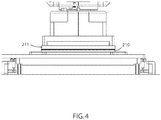
- the plurality of factors include steps, characteristics, movements, timing, and the like, which lead to the second substrate 211 to be optically bonded to the first substrate 210, as shown in FIG. 4 .
- the factors may help determine a bond sequence of various commands that cause the robotic placement head 220 to lower the second substrate 211 onto the first substrate 210 and achieve a proper optical bond.
- the plurality of factors may include a time between moves, a speed of descent, a movement along an X axis, a movement along a Y axis, a movement along a Z axis, a tilt, a rotation, and the like, which may be helpful in determining the exact bond sequence to arrive at the optical bond position.
- the camera 111 may be capturing a real-time feed of the adhesive fill reaction, from underneath the transparent datum 225.
- the camera 111 may transmit the real-time feed to the computing system 120, which may then transmit the feed signal to the display 112.
- the operator may receive live feedback by viewing the display 112 to ensure a proper wavefront progression of the adhesive during contact and eventual bonding.
- the operator may input commands to the controller 110 based on the video feed displayed by the display 112, wherein the control signals sent from the controller 110 to the computing system 120 are being recorded by the control signal recording module 132.
- embodiments of the computing system 120 may include an analytics module 133.
- Embodiments of the analytics module 133 may include one or more components of hardware and/or software program code for analyzing the operator feedback control signals to determine a bonding sequence for automatically optically bonding the first substrate 210 and the second substrate 211.
- embodiments of the analytics module 133 may analyze the plurality of factors from the recorded operator feedback control signals to create a sequential order for automatically controllably contacting the first substrate and the second substrate, based on the plurality of factors.
- the bonding sequence for automatically bonding the first substrate 210 and the second substrate 211 may include one or more commands for programming a movement of the robotic placement head 220 to optically bond the substrates 210, 211.
- the automatic bonding sequence may essentially be the exact moves/command signals that the operator input into the controller 110, except that the computing system 120 may provide the signals/instructions directly and automatically to the robotic placement head 220, without operator involvement.
- the computing system 120 may provide the signals/instructions directly and automatically to the robotic placement head 220, without operator involvement.
- an automatic bond sequence based on an initial or single run-though of the operator controlling the controller 110, subsequent applications for complete optical bonding may be done entirely automatic (i.e. no stopping automatic process and waiting for operator to use controller 110.
- Embodiments of the bonding sequence may be used to contact a new first substrate of the same size as the first substrate 210 and a new second substrate of the same size as the second substrate 211, in a subsequent optical bonding operation, instead of the operator operating the controller 110.
- embodiments of the analytics module 133 may derive a sequential order from the recorded signals, and may populate a database or programming directory that the computing system 120 accesses for providing commands to the robotic placement head 220, so that the subsequent optical bonding steps are automatically performed.
- the plurality of factors stored in the database may be further manipulated through a graphical user interface (e.g. a "bond manager tab") of the computing system 120, displayed on display 112.
- a graphical user interface e.g. a "bond manager tab”
- an operator may interact with the graphical user interface to optimize the bond routine/sequence in a more refined manner making changes to any given factor; changes may be minute changes to refine the process.
- the first pass 'teach mode i.e. operator controlling controller 112 attempts to achieve a close to perfect bonding program/sequence.
- a line-by-line editing of the bond step variables such as speed, distance, dwell time, etc., may be performed using the graphical user interface to optimize the bond sequence for subsequent applications.
- the plurality of factors may be delineated in the GUI "bond manager tab" so each discrete value can be manipulated by keystroke entry, to optimize the bond sequence.
- an end user may utilize machine 200 having computing system 120 to perform repeatable, automatic optical bonding processes for various size substrates because an optimal bonding sequence may be learned by the computing system 120 in the field.
- An initial use for the machine 200 may involve optical bonding of covers/displays of smartphones.
- the machine 200 may ship to the end user, and an operator in the field may take the controls of the controller 110 to optical bond the cover/display of the smartphone using the real-time feedback on the display 112, courtesy of the camera 111 disposed in the interior 215 of the machine 200. Then, after the exact desired bonding sequence is learned by the computing system 120, subsequent runs may be completely automated.
- the end user desires to use machine 200 for optically bonding a cover/display for a tablet, which is a larger substrate area (and potentially a different adhesive, etc.)
- the end user need not contact the manufacturer and have the machine 200 entirely reprogrammed, but may indicate via a GUI of the software to initiate a learning process or tool, which will perform the steps described above, allowing an operator to use the controller 110 to manually optically bond the newly sized substrates using the feedback from the display 112. After the exact desired bonding sequence is learned by the computing system 120, subsequent runs may be completely automated.
- embodiments of the computing system 120 may include an inspection module 134.
- Embodiments of the inspection module 134 may include one or more components of hardware and/or software program code for inspecting the bonded substrates 210, 211 for a presence of air bubbles, foreign objects or debris, prior to resuming the automated process, or prior to initiating a curing step, wherein the inspecting includes examining a video or image of the bonded substrates 210, 211 captured by a camera 111 positioned beneath the first substrate 210. If air pockets are detected, then the inspection module 134 may cancel the curing step, and request new substrates and the process to start over.
- the inspection module 134 may transmit a confirmation signal to the computing system 120, or may simply not send a cancel signal.
- the curing step involves actuating, by the processor of the computing system 120, a UV source 235 to move into a position beneath the bonded substrates 210, 211, which may cure the adhesive bonding the substrate 210, 211.
- Embodiments of the UV source 235 may an array of UV emitting lamps/lights, LED lamps/lights, mercury halide, or other UV emitting devices.
- Various UV sources 235 may be selected based on different wavelengths output by the UV device, which may be ideal for a particular adhesive used for the a particular project.
- Embodiments of the computing system 120 may be equipped with a memory device 142 which may store the machine data and/or sequence data, and a processor 141 for implementing the tasks associated with the automatic bonding sequence learning system 100. Furthermore, various tasks and specific functions of the modules of the computing system 120 may be performed by additional modules, or may be combined into other module(s) to reduce the number of modules.
- FIG. 5 depicts a flow chart of a method 300 for customizing an automated bonding sequence, in accordance with embodiments of the present invention.
- Embodiments of the method 300 for customizing an automated bonding sequence may begin at step 301 wherein a close proximity between the first substrate 210 and the second substrate 211 is detected.
- step 302 stops the automated process, and may prompt a user/operator to use a controller 110 to maneuver the robotic placement head 220 to optically bond the substrates 210, 211, in view of the real-time feedback provided by the camera 111 in the machine 200.
- Step 303 records the operator controller signals as the substrates 210, 211 are brought into contact.
- Step 304 analyzes the controller signals to determine an automatic bonding sequence, which may be used for subsequent applications/processes without operator intervention for maneuvering the robotic placement head 220.
- Step 305 inspects the bonded substrates 210, 211 for air pockets, prior to a curing step to cure the adhesive.
- Step 306 resumes the automated process, which may include actuating the UV source 235 to move (e.g. along a track within the machine 200) into a position below the bonded substrates and cure the adhesive while the robotic gripper continues to hold the upper substrate at the desired X, Y, Z and rotational position. The result is properly oriented and desired bond thickness product being cured before removal to the remaining automated steps.
- the curing may be done in the same interior region 215 of the machine 200 as the optical bonding because the datum 225, and the substrates are transparent.
- the computing system 120 automatically determines or suggests a bonding sequence, without operator involvement, or learning a sequence as input by an operator using a controller 110.
- FIG. 6 depicts a flow chart of a method 400 for automatically determining a bonding sequence, in accordance with embodiments of the present invention.
- Step 401 detects a close proximity between the first substrate 210 and the second substrate 211.
- step 402 scans an area (e.g. gap) between the substrates 210, 210. The scanning may be performed by a laser, a sensor, a camera, an ultrasound sensor, and the like, which may be positioned within the machine 200.
- Step 404 analyzes the data returned to the computing system 120.
- the scanning of the area may help determine how much the robotic placement head 220 has to move in each of the X, Y, Z axes, which may also take into account a fill height of the adhesive, and well as the chemical and physical properties of the adhesive (e.g. viscosity, etc.). Further data may retrieved by one or more sensors, such as a weight of the substrate(s), a thickness of the substrate(s), a fill height of the adhesive, and the like.
- the computing system 120 may also analyze the display 112 for rate of progression of the wavefront of the adhesive's capillary effect when the substrates 210, 211 are being bonded, to aid in the determining of the automatic bonding sequence.
- Step 405 inspects the bonded substrates 210, 211 for air pockets, prior to a curing step to cure the adhesive.
- Step 406 resumes the automated process and stores the bonding sequence, which may include actuating the UV source 235 to move (e.g. along a track within the machine 200) into a position below the bonded substrates and cure the adhesive.
- the curing may be done in the same interior region 215 of the machine 200 as the optical bonding because the datum 225, and the substrates are transparent.
- method 400 may be repeated
- FIG. 7 depicts a block diagram of a computer system for the automatic bonding sequence learning system of FIG. 1 , capable of implementing methods for customizing an automated bonding sequence of FIGs. 5-6 , in accordance with embodiments of the present invention.
- the computer system 500 may generally comprise a processor 591, an input device 592 coupled to the processor 591, an output device 593 coupled to the processor 591, and memory devices 594 and 595 each coupled to the processor 591.
- the input device 592, output device 593 and memory devices 594, 595 may each be coupled to the processor 591 via a bus.
- Processor 591 may perform computations and control the functions of computer 500, including executing instructions included in the computer code 597 for the tools and programs capable of implementing a method for customizing an automated bonding sequence, in the manner prescribed by the embodiments of FIGS. 5-6 using the automatic bonding sequence learning system of FIG. 1 , wherein the instructions of the computer code 597 may be executed by processor 591 via memory device 595.
- the computer code 597 may include software or program instructions that may implement one or more algorithms for implementing the methods of customizing an automated bonding sequence, as described in detail above.
- the processor 591 executes the computer code 597.
- Processor 591 may include a single processing unit, or may be distributed across one or more processing units in one or more locations (e.g., on a client and server).
- the memory device 594 may include input data 596.
- the input data 596 includes any inputs required by the computer code 597.
- the output device 593 displays output from the computer code 597.
- Either or both memory devices 594 and 595 may be used as a computer usable storage medium (or program storage device) having a computer readable program embodied therein and/or having other data stored therein, wherein the computer readable program comprises the computer code 597.
- a computer program product (or, alternatively, an article of manufacture) of the computer system 500 may comprise said computer usable storage medium (or said program storage device).
- Memory devices 594, 595 include any known computer readable storage medium, including those described in detail below.
- cache memory elements of memory devices 594, 595 may provide temporary storage of at least some program code (e.g., computer code 597) in order to reduce the number of times code must be retrieved from bulk storage while instructions of the computer code 597 are executed.
- memory devices 594, 595 may reside at a single physical location, including one or more types of data storage, or be distributed across a plurality of physical systems in various forms. Further, memory devices 594, 595 can include data distributed across, for example, a local area network (LAN) or a wide area network (WAN). Further, memory devices 594, 595 may include an operating system (not shown) and may include other systems not shown in FIG. 7 .
- LAN local area network
- WAN wide area network
- the computer system 500 may further be coupled to an Input/output (I/O) interface and a computer data storage unit.
- I/O interface may include any system for exchanging information to or from an input device 592 or output device 593.
- the input device 592 may be, inter alia, a keyboard, a mouse, etc. or in some embodiments the sensors 110.
- the output device 593 may be, inter alia, a printer, a plotter, a display device (such as a computer screen), a magnetic tape, a removable hard disk, a floppy disk, etc.
- the memory devices 594 and 595 may be, inter alia, a hard disk, a floppy disk, a magnetic tape, an optical storage such as a compact disc (CD) or a digital video disc (DVD), a dynamic random access memory (DRAM), a read-only memory (ROM), etc.
- the bus may provide a communication link between each of the components in computer 500, and may include any type of transmission link, including electrical, optical, wireless, etc.
- An I/O interface may allow computer system 500 to store information (e.g., data or program instructions such as program code 597) on and retrieve the information from computer data storage unit (not shown).
- Computer data storage unit includes a known computer-readable storage medium, which is described below.
- computer data storage unit may be a non-volatile data storage device, such as a magnetic disk drive (i.e., hard disk drive) or an optical disc drive (e.g., a CD-ROM drive which receives a CD-ROM disk).
- the data storage unit may include a knowledge base or data repository 125 as shown in FIG. 1 .
- the present invention may be a method; in a second embodiment, the present invention may be a system; and in a third embodiment, the present invention may be a computer program product. Any of the components of the embodiments of the present invention can be deployed, managed, serviced, etc. by a service provider that offers to deploy or integrate computing infrastructure with respect to an automated bonding sequence systems and methods.
- an embodiment of the present invention discloses a process for supporting computer infrastructure, where the process includes providing at least one support service for at least one of integrating, hosting, maintaining and deploying computer-readable code (e.g., program code 597) in a computer system (e.g., computer 500) including one or more processor(s) 591, wherein the processor(s) carry out instructions contained in the computer code 597 causing the computer system to customize an automated bonding sequence.
- a process for supporting computer infrastructure where the process includes integrating computer-readable program code into a computer system including a processor.
- the step of integrating includes storing the program code in a computer-readable storage device of the computer system through use of the processor.
- the program code upon being executed by the processor, implements a method of customizing an automated bonding sequence.
- the present invention discloses a process for supporting, deploying and/or integrating computer infrastructure, integrating, hosting, maintaining, and deploying computer-readable code into the computer system 500, wherein the code in combination with the computer system 500 is capable of performing a method for customizing an automated bonding sequence.
- a computer program product of the present invention comprises one or more computer readable hardware storage devices having computer readable program code stored therein, said program code containing instructions executable by one or more processors of a computer system to implement the methods of the present invention.
- a computer system of the present invention comprises one or more processors, one or more memories, and one or more computer readable hardware storage devices, said one or more hardware storage devices containing program code executable by the one or more processors via the one or more memories to implement the methods of the present invention.
- the present invention may be a system, a method, and/or a computer program product at any possible technical detail level of integration
- the computer program product may include a computer readable storage medium (or media) having computer readable program instructions thereon for causing a processor to carry out aspects of the present invention
- the computer readable storage medium can be a tangible device that can retain and store instructions for use by an instruction execution device.
- the computer readable storage medium may be, for example, but is not limited to, an electronic storage device, a magnetic storage device, an optical storage device, an electromagnetic storage device, a semiconductor storage device, or any suitable combination of the foregoing.
- a non-exhaustive list of more specific examples of the computer readable storage medium includes the following: a portable computer diskette, a hard disk, a random access memory (RAM), a read-only memory (ROM), an erasable programmable read-only memory (EPROM or Flash memory), a static random access memory (SRAM), a portable compact disc read-only memory (CD-ROM), a digital versatile disk (DVD), a memory stick, a floppy disk, a mechanically encoded device such as punch-cards or raised structures in a groove having instructions recorded thereon, and any suitable combination of the foregoing.
- RAM random access memory
- ROM read-only memory
- EPROM or Flash memory erasable programmable read-only memory
- SRAM static random access memory
- CD-ROM compact disc read-only memory
- DVD digital versatile disk
- memory stick a floppy disk
- a mechanically encoded device such as punch-cards or raised structures in a groove having instructions recorded thereon
- a computer readable storage medium is not to be construed as being transitory signals per se, such as radio waves or other freely propagating electromagnetic waves, electromagnetic waves propagating through a waveguide or other transmission media (e.g., light pulses passing through a fiber-optic cable), or electrical signals transmitted through a wire.
- Computer readable program instructions described herein can be downloaded to respective computing/processing devices from a computer readable storage medium or to an external computer or external storage device via a network, for example, the Internet, a local area network, a wide area network and/or a wireless network.
- the network may comprise copper transmission cables, optical transmission fibers, wireless transmission, routers, firewalls, switches, gateway computers and/or edge servers.
- a network adapter card or network interface in each computing/processing device receives computer readable program instructions from the network and forwards the computer readable program instructions for storage in a computer readable storage medium within the respective computing/processing device.
- Computer readable program instructions for carrying out operations of the present invention may be assembler instructions, instruction-set-architecture (ISA) instructions, machine instructions, machine dependent instructions, microcode, firmware instructions, state-setting data, configuration data for integrated circuitry, or either source code or object code written in any combination of one or more programming languages, including an object oriented programming language such as Smalltalk, C++, or the like, and procedural programming languages, such as the "C" programming language or similar programming languages.
- the computer readable program instructions may execute entirely on the user's computer, partly on the user's computer, as a stand-alone software package, partly on the user's computer and partly on a remote computer or entirely on the remote computer or server.
- the remote computer may be connected to the user's computer through any type of network, including a local area network (LAN) or a wide area network (WAN), or the connection may be made to an external computer (for example, through the Internet using an Internet Service Provider).
- electronic circuitry including, for example, programmable logic circuitry, field-programmable gate arrays (FPGA), or programmable logic arrays (PLA) may execute the computer readable program instructions by utilizing state information of the computer readable program instructions to personalize the electronic circuitry, in order to perform aspects of the present invention.
- These computer readable program instructions may be provided to a processor of a general purpose computer, special purpose computer, or other programmable data processing apparatus to produce a machine, such that the instructions, which execute via the processor of the computer or other programmable data processing apparatus, create means for implementing the functions/acts specified in the flowchart and/or block diagram block or blocks.
- These computer readable program instructions may also be stored in a computer readable storage medium that can direct a computer, a programmable data processing apparatus, and/or other devices to function in a particular manner, such that the computer readable storage medium having instructions stored therein comprises an article of manufacture including instructions which implement aspects of the function/act specified in the flowchart and/or block diagram block or blocks.
- the computer readable program instructions may also be loaded onto a computer, other programmable data processing apparatus, or other device to cause a series of operational steps to be performed on the computer, other programmable apparatus or other device to produce a computer implemented process, such that the instructions which execute on the computer, other programmable apparatus, or other device implement the functions/acts specified in the flowchart and/or block diagram block or blocks.
- each block in the flowchart or block diagrams may represent a module, segment, or portion of instructions, which comprises one or more executable instructions for implementing the specified logical function(s).
- the functions noted in the blocks may occur out of the order noted in the Figures.
- two blocks shown in succession may, in fact, be executed substantially concurrently, or the blocks may sometimes be executed in the reverse order, depending upon the functionality involved.
Landscapes
- Engineering & Computer Science (AREA)
- Mechanical Engineering (AREA)
- Manufacturing & Machinery (AREA)
- Chemical & Material Sciences (AREA)
- Physics & Mathematics (AREA)
- General Physics & Mathematics (AREA)
- Signal Processing (AREA)
- Human Computer Interaction (AREA)
- Multimedia (AREA)
- Automation & Control Theory (AREA)
- Quality & Reliability (AREA)
- Health & Medical Sciences (AREA)
- Ophthalmology & Optometry (AREA)
- General Chemical & Material Sciences (AREA)
- Life Sciences & Earth Sciences (AREA)
- Chemical Kinetics & Catalysis (AREA)
- Ceramic Engineering (AREA)
- Geochemistry & Mineralogy (AREA)
- Materials Engineering (AREA)
- Organic Chemistry (AREA)
- Container, Conveyance, Adherence, Positioning, Of Wafer (AREA)
- Coating Apparatus (AREA)
- Theoretical Computer Science (AREA)
- Computer Vision & Pattern Recognition (AREA)
- Laminated Bodies (AREA)
- Lining Or Joining Of Plastics Or The Like (AREA)
- Devices For Indicating Variable Information By Combining Individual Elements (AREA)
- Application Of Or Painting With Fluid Materials (AREA)
- Manipulator (AREA)
- Adhesives Or Adhesive Processes (AREA)
- Studio Devices (AREA)
- Length Measuring Devices By Optical Means (AREA)
- Electric Connection Of Electric Components To Printed Circuits (AREA)
Description
- The following relates to an automatic bonding sequence learning system, and more specifically to embodiments of determining a bonding sequence for optically bonding two substrates.
- Optical bonding involves bonding two substrates together using an optically clear adhesive. An ideal bond does not include the presence of air pockets between the substrates. To prevent or hinder a formation of air pockets, the substrates must be bonded together to create a capillary effect of the adhesive sandwiched between the substrates. A method for the optical bonding of a first substrate to a second substrate is disclosed in
US 2008/0216952 A1 , wherein the first substrate is first brought to a position wherein it is in close proximity with the second substrate such that a resin bridge is formed. - A first aspect relates to a method for customizing an automated bonding sequence, the method comprising: detecting, by a processor of a computing system, that a first substrate is in close proximity with the a second substrate, during an optical bonding operation such that an adhesive on the first substrate is not yet in contact with at least one of: the second substrate and an adhesive on the second substrate, stopping, by the processor, an automated process of optically bonding of the optical bonding operation, in response to the detecting, recording, by the processor, operator feedback control signals, the operator feedback control signals being received from a controller being operated by an operator to contact the first substrate and the second substrate, analyzing, by the processor, the operator feedback control signals to determine a bonding sequence for automatically optically bonding the first substrate and the second substrate, and resuming, by the processor, the automated process of the optical bonding operation.
- A second aspect relates to a computer system, comprising: a processor, a memory device coupled to the processor, and a computer readable storage device coupled to the processor, wherein the storage device contains program code executable by the processor via the memory device to implement a method customizing an automated bonding sequence, the method comprising: detecting, by a processor of a computing system, that a first substrate is in close proximity with the a second substrate, during an optical bonding operation such that an adhesive on the first substrate is not yet in contact with at least one of: the second substrate and an adhesive on the second substrate, stopping, by the processor, an automated process of optically bonding of the optical bonding operation, in response to the detecting, recording, by the processor, operator feedback control signals, the operator feedback control signals being received from a controller being operated by an operator to contact the first substrate and the second substrate, analyzing, by the processor, the operator feedback control signals to determine a bonding sequence for automatically optically bonding the first substrate and the second substrate, and resuming, by the processor, the automated process of the optical bonding operation.
- A third aspect relates to a computer program product, comprising a computer readable hardware storage device storing a computer readable program code, the computer readable program code comprising an algorithm that when executed by a computer processor of a computing system implements a method customizing an automated bonding sequence, the method comprising: detecting, by a processor of a computing system, that a first substrate is in close proximity with the a second substrate, during an optical bonding operation such that an adhesive on the first substrate is not yet in contact with at least one of: the second substrate and an adhesive on the second substrate, stopping, by the processor, an automated process of optically bonding of the optical bonding operation, in response to the detecting, recording, by the processor, operator feedback control signals, the operator feedback control signals being received from a controller being operated by an operator to contact the first substrate and the second substrate, analyzing, by the processor, the operator feedback control signals to determine a bonding sequence for automatically optically bonding the first substrate and the second substrate, and resuming, by the processor, the automated process of the optical bonding operation.
-
-
FIG. 1 depicts a block diagram of automatic bonding sequence learning system, in accordance with embodiments of the present invention. -
FIG. 2A depicts an optical bonding machine, in accordance with embodiments of the present invention. -
FIG. 2B depicts a schematic view of an optical bonding assembly located within an interior region of the optical bonding machine ofFIG. 2A , in accordance with embodiments of the present invention. -
FIG. 2C depicts a schematic view from underneath the optical bonding assembly ofFIG. 2B , in accordance with embodiments of the present invention. -
FIG. 3 depicts a close proximity between the first substrate and the second substrate, during an optical bonding process, in accordance with embodiments of the present invention. -
FIG. 4 depicts the substrates in an optically bonded position, in accordance with embodiments of the present invention. -
FIG. 5 depicts a flow chart of a method for customizing an automated bonding sequence, in accordance with embodiments of the present invention. -
FIG. 6 depicts a flow chart of a method for automatically determining a bonding sequence, in accordance with embodiments of the present invention. -
FIG. 7 depicts a block diagram of a computer system for the automatic bonding sequence learning system ofFIG. 1 , capable of implementing methods for customizing an automated bonding sequence ofFIGs. 5-6 , in accordance with embodiments of the present invention. - Referring to the drawings,
FIG. 1 depicts a block diagram of automatic bondingsequence learning system 100, in accordance with embodiments of the present invention. Embodiments of the automatic bondingsequence learning system 100 may determine a customized bonding sequence for various sized substrates and various optically clear adhesives during an automated optical bonding process. The automatic bondingsequence learning system 100 may record control signals from an operator using a controller to bring the substrates together during an initial bonding sequence, and then analyze the signals to determine an automated bonding sequence to be used in subsequent applications/processes. For instance, for a new or initial automated optical bonding process, an operator may manually control the actual bonding process step (e.g. controllably lowering the top substrate onto the bottom substrate) of the automated process to ensure a proper wavefront progression of the adhesive and end result (e.g. no air pockets, full visible area wet out, desired bond thickness), given the size of the substrates and adhesive used for a particular application. Thus, an optical bonding machine provided to an end user may be flexible to perform an automated optical bonding process for more than one size substrate(s) or application, wherein the appropriate bonding sequence may be automatically determined based on an initial (e.g. a single unit being bonded) run. - Embodiments of the automatic bonding
sequence learning system 100 may include acomputing system 120. Embodiments of thecomputing system 120 may be an onboard computing system of a machine, such as an optical bonding machine. In other embodiments, thecomputing system 120 may be a server or remote computing system communicatively coupled to an onboard computing system of the machine, wherein thecomputing system 120 services requests and performs the functions of the automatic bondingsequence learning system 100. - Embodiment of automatic bonding
sequence learning system 100 may comprise acontroller 110, acamera 111, and adisplay 112 communicatively coupled to acomputing system 120 via an I/O interface 150 and/or over anetwork 107. For instance, thecontroller 110, thecamera 111, and thedisplay 112 may be connected via an I/O interface 150 tocomputer system 120. The number ofcontrollers 110,cameras 111, and displays 112 connecting tocomputer system 120 viadata bus lines network 107 may vary from embodiment to embodiment. - As shown in
FIG 1 , thecontroller 110 may transmit control signals/data (e.g. "machine data" and/or "bonding sequence data") by connecting tocomputing system 120 via the data bus lines 155 to an I/O interface 150. Thecamera 111 may transmit image and/or video data ("bonding sequence data) by connecting to computingsystem 120 via the data bus lines 155 to an I/O interface 150. Thedisplay 112 may receive display data to display the bonding sequence data transmitted to thecomputing system 120 by thecamera 111. An I/O interface 150 may refer to any communication process performed between thecomputer system 120 and the environment outside of thecomputer system 120, for example, thecontroller 110, thecamera 111, and thedisplay 111. Input to thecomputing system 120 may refer to the signals or instructions sent to thecomputing system 120, for example, the controller signals transmitted by thecontroller 110, while output may refer to the signals sent out from thecomputer system 120 to thedisplay 110, or other components of the optical bonding machine (e.g. end effector, LED array, robotic placement head which picks and places the top substrate). - Alternatively, the
controller 110,camera 111, anddisplay 112 may transmit or receive data by connecting to computingsystem 120 over thenetwork 107. Anetwork 107 may refer to a group of two or more computer systems linked together. Network 107 may be any type of computer network known by individuals skilled in the art. Examples ofcomputer networks 107 may include a LAN, WAN, campus area networks (CAN), home area networks (HAN), metropolitan area networks (MAN), an enterprise network, cloud computing network (either physical or virtual) e.g. the Internet, a cellular communication network such as GSM or CDMA network or a mobile communications data network. The architecture of thecomputer network 107 may be a peer-to-peer network in some embodiments, wherein in other embodiments, thenetwork 107 may be organized as a client/server architecture. In an exemplary embodiment,network 107 may be an Ethernet network of a machine, such as an optical bonding machine. - In some embodiments, the
network 107 may further comprise, in addition to thecomputer system 120,controller 110,camera 111, anddisplay 112, a connection to one or more network accessible knowledge bases containing information of one or more users,network repositories 114 or other systems connected to thenetwork 107 that may be considered nodes of thenetwork 107. In some embodiments, where thecomputing system 120 ornetwork repositories 114 allocate resources to be used by the other nodes of thenetwork 107, thecomputer system 120 andnetwork repository 114 may be referred to as servers. - The
network repository 114 may be a data collection area on thenetwork 107 which may back up and save all the data transmitted back and forth between the nodes of thenetwork 107. For example, thenetwork repository 114 may be a data center saving and cataloging machine data and/or bonding sequence data sent by one or more of thecontroller 110,camera 111 or received bydisplay 112, to generate both historical and predictive reports regarding a particular bonding sequence for a given application or project. In some embodiments, a data collection center housing thenetwork repository 114 may include an analytic module capable of analyzing each piece of data being stored by thenetwork repository 114. Further, thecomputer system 120 may be integrated with or as a part of the data collection center housing thenetwork repository 114. In some alternative embodiments, thenetwork repository 114 may be a local repository (not shown) that is connected to thecomputer system 120. - With continued reference to
FIG. 1 , embodiments of thecomputing system 120 may receive the machine data and/or bonding sequence data from thecontroller 110 orcamera 111 which may be positioned within an interior of the optical bonding machine, on an exterior surface of the machine, remotely, in an environment shared by an operator, or otherwise disposed in a location that can result in obtaining machine data and bonding sequence data. In an exemplary embodiment, thecontroller 110 may be removably attached to the machine, connected to thecomputing system 120 via cord, so that an operator may operate thecontroller 110 with a view of thedisplay 112, which is coupled to thecomputing system 120. Thecontroller 110 may also be a remote controller connecting to thecomputing system 120 vianetwork 107, or other wireless network. Thecamera 111 may be positioned underneath the bottom substrate, while thedisplay 112 may be attached to a frame of a machine. -
FIGs. 2A-2B depict embodiments of an optical bonding machine, which may be operated and/or controlled bycomputing system 120.FIG. 2A depicts anoptical bonding machine 200, in accordance with embodiments of the present invention. Embodiments of theoptical bonding machine 200 may include aninterior region 215, wherein various components, such as the robotic placement head that picks and places one of the substrates, datum,camera 111, end effector, etc., reside for carrying out an optical bonding process. One ormore displays 112 may be attached to a frame of themachine 200, for viewing image or video data captured by thecamera 111 located underneath a datum that supports the bottom substrate.FIG. 2B depicts a schematic view of anoptical bonding assembly 250 located within theinterior region 215 of theoptical bonding machine 200 ofFIG. 2A , in accordance with embodiments of the present invention. Embodiments of theoptical bonding assembly 250 may represent only a number of components associated with theoptical bonding machine 200, wherein theoptical bonding machine 200 may include several other components, including an end effector, gantry robot, X, Y, Z and theta , servo actuators, and the like. Embodiments of theoptical bonding assembly 250 may include adatum 225, which may support afirst substrate 210, such as a bottom substrate. Thedatum 225 may be transparent, so that the bonding between thefirst substrate 210 and asecond substrate 210 may be visible from thecamera 110 disposed underneath thedatum 225. Thefirst substrate 210 and thesecond substrate 211 may be an optically clear substrate, such as a piece of glass for use as a display or cover glass for a computing device or other smart surface (e.g. smart phone, tablet, vehicle touch screen, etc.). One or both of thefirst substrate 210 and thesecond substrate 211 may be a capacitive screen. Further, embodiments of theoptical bonding assembly 150 may include arobotic placement head 220, for picking and placing thesecond substrate 211 into contact with thefirst substrate 210. Therobotic placement head 220 may have movement along the X axis, Y axis, and Z axis, as well as rotational and tilting capabilities, for example, through ball screw slides and gantry robot configuration. Therobotic placement head 220 may move in a manner to optically bond thesubstrates camera 111 captures a progression of the adhesive between thesubstrates substrates computing system 120 so thecomputing system 120 can display the footage ondisplay 112, during the bonding process.FIG. 2C depicts a schematic view from underneath theoptical bonding assembly 250 ofFIG. 2B , in accordance with embodiments of the present invention. Thecamera 111 may be positioned underneath atransparent datum 225 to capture the flow of the adhesives between thesubstrates optical bond assembly 250 may include a UV source, such asLED array 235. TheUV source 235 may be actuated by thecomputing system 120 to move in a position directly underneath thedatum 225 to cure the adhesive, after thesubstrates - Referring back to
FIG. 1 , embodiments of thecomputing system 120 may include asubstrate detection module 131, a controlsignal recording module 132, ananalytics module 133, and an inspection module 135. A "module" may refer to a hardware based module, software based module or a module may be a combination of hardware and software. Embodiments of hardware based modules may include self-contained components such as chipsets, specialized circuitry and one or more memory devices, while a software-based module may be part of a program code or linked to the program code containing specific programmed instructions, which may be loaded in the memory device of thecomputer system 120. A module (whether hardware, software, or a combination thereof) may be designed to implement or execute one or more particular functions or routines. - Embodiments of the
substrate detection module 131 may include one or more components of hardware and/or software program code for detecting that afirst substrate 210 is in close proximity with the a second substrate 211 (or vice versa), during an optical bonding operation.FIG. 3 depicts a close proximity between thefirst substrate 210 and thesecond substrate 211, during an optical bonding process, in accordance with embodiments of the present invention. Close proximity may mean that a small gap exists between thefirst substrate 210 and thesecond substrate 211, wherein an adhesive material dispensed on thefirst substrate 210 has yet to come into contact with an adhesive material on the second substrate 211 (e.g. a dot of adhesive on the underside of the second substrate). The gap between thefirst substrate 210 and thesecond substrate 211 may be smaller or significantly smaller than the gap between thesubstrates FIGs. 2A-2C . The gap when in close proximity may be several millimeters or larger. Embodiments of thesubstrate detection module 131 may detect when therobotic placement head 220 advanced close enough to thedatum 225, to determine that a close proximity exists. In an exemplary embodiment, the movement of therobotic placement head 220 is pre-programmed to automatically reach a close proximity, and in response to arriving at a location of close proximity, thesubstrate detection module 131 may stop the movement of therobotic placement head 220. In another exemplary embodiment, thesubstrate detection module 131 may confirm thatsubstrates first substrate 210, and transmitting a signal to thecomputing system 120 to cease movement of therobotic placement head 220 in response to a detection of a lead edge of thesecond substrate 210. In yet another exemplary embodiment, close proximity is detected using a touch probe early on in the process to measure the thickness of eachsubstrate computing system 120 causes therobotic placement head 220 to remain in a position where thefirst substrate 210 and thesecond substrate 211 are in close proximity, and the automated process of the optical bonding machine is suspended, stopped, ceased, or temporarily suspended or stopped. In response to the stoppage of the automated process, thecomputing system 120 may prompt an operator to take controls of thecontroller 110 to control the movement of therobotic placement head 220 to close the distance between thefirst substrate 210 and thesecond substrate 211 to effectuate a proper optical bond without formation of air pockets. - Embodiments of the
computing system 120 may include a controlsignal recording module 132. Embodiments of the controlsignal recording module 132 may include one or more components of hardware and/or software program code for recording, storing, tracking, monitoring, learning, etc. operator feedback control signals received from thecontroller 110 being operated by an operator to contact thefirst substrate 210 and thesecond substrate 211. For instance, thecontroller 110 may be coupled to thecomputing system 120 as shown inFIG. 1 , and as the operator operates thecontroller 110, precise control signals are being sent from thecontroller 110 to thecomputing system 120 to effectuate the movement of therobotic placement head 220. Embodiments of the controlsignal recording module 132 may record, track, store, monitor, etc., those control signals sent from thecontroller 110. The control signals may be stored in thedata repository 125 of thecomputing system 120, or may be transmitted to a remote storage device overnetwork 107. Furthermore, the control signals being recorded by the controlsignal recording module 132 may include a plurality of factors from the recorded operator feedback control signals. The plurality of factors include steps, characteristics, movements, timing, and the like, which lead to thesecond substrate 211 to be optically bonded to thefirst substrate 210, as shown inFIG. 4 . In other words, the factors may help determine a bond sequence of various commands that cause therobotic placement head 220 to lower thesecond substrate 211 onto thefirst substrate 210 and achieve a proper optical bond. The plurality of factors may include a time between moves, a speed of descent, a movement along an X axis, a movement along a Y axis, a movement along a Z axis, a tilt, a rotation, and the like, which may be helpful in determining the exact bond sequence to arrive at the optical bond position. - As the operator controls the
robotic placement head 220 to effectuate an optical bond, thecamera 111 may be capturing a real-time feed of the adhesive fill reaction, from underneath thetransparent datum 225. Thecamera 111 may transmit the real-time feed to thecomputing system 120, which may then transmit the feed signal to thedisplay 112. The operator may receive live feedback by viewing thedisplay 112 to ensure a proper wavefront progression of the adhesive during contact and eventual bonding. The operator may input commands to thecontroller 110 based on the video feed displayed by thedisplay 112, wherein the control signals sent from thecontroller 110 to thecomputing system 120 are being recorded by the controlsignal recording module 132. - Referring back to
FIG. 1 , embodiments of thecomputing system 120 may include ananalytics module 133. Embodiments of theanalytics module 133 may include one or more components of hardware and/or software program code for analyzing the operator feedback control signals to determine a bonding sequence for automatically optically bonding thefirst substrate 210 and thesecond substrate 211. For instance, embodiments of theanalytics module 133 may analyze the plurality of factors from the recorded operator feedback control signals to create a sequential order for automatically controllably contacting the first substrate and the second substrate, based on the plurality of factors. The bonding sequence for automatically bonding thefirst substrate 210 and thesecond substrate 211 may include one or more commands for programming a movement of therobotic placement head 220 to optically bond thesubstrates controller 110, except that thecomputing system 120 may provide the signals/instructions directly and automatically to therobotic placement head 220, without operator involvement. Thus, by analyzing and determining an automatic bond sequence based on an initial or single run-though of the operator controlling thecontroller 110, subsequent applications for complete optical bonding may be done entirely automatic (i.e. no stopping automatic process and waiting for operator to usecontroller 110. Embodiments of the bonding sequence may be used to contact a new first substrate of the same size as thefirst substrate 210 and a new second substrate of the same size as thesecond substrate 211, in a subsequent optical bonding operation, instead of the operator operating thecontroller 110. Moreover, embodiments of theanalytics module 133 may derive a sequential order from the recorded signals, and may populate a database or programming directory that thecomputing system 120 accesses for providing commands to therobotic placement head 220, so that the subsequent optical bonding steps are automatically performed. - Furthermore, the plurality of factors stored in the database, such as
data repository 125, may be further manipulated through a graphical user interface (e.g. a "bond manager tab") of thecomputing system 120, displayed ondisplay 112. For example, an operator may interact with the graphical user interface to optimize the bond routine/sequence in a more refined manner making changes to any given factor; changes may be minute changes to refine the process. The first pass 'teach mode" (i.e. operator controlling controller 112) attempts to achieve a close to perfect bonding program/sequence. Then, a line-by-line editing of the bond step variables, such as speed, distance, dwell time, etc., may be performed using the graphical user interface to optimize the bond sequence for subsequent applications. As an example, the plurality of factors may be delineated in the GUI "bond manager tab" so each discrete value can be manipulated by keystroke entry, to optimize the bond sequence. - In an exemplary embodiment, an end user may utilize
machine 200 havingcomputing system 120 to perform repeatable, automatic optical bonding processes for various size substrates because an optimal bonding sequence may be learned by thecomputing system 120 in the field. An initial use for themachine 200 may involve optical bonding of covers/displays of smartphones. Themachine 200 may ship to the end user, and an operator in the field may take the controls of thecontroller 110 to optical bond the cover/display of the smartphone using the real-time feedback on thedisplay 112, courtesy of thecamera 111 disposed in theinterior 215 of themachine 200. Then, after the exact desired bonding sequence is learned by thecomputing system 120, subsequent runs may be completely automated. If the same end user desires to usemachine 200 for optically bonding a cover/display for a tablet, which is a larger substrate area (and potentially a different adhesive, etc.), the end user need not contact the manufacturer and have themachine 200 entirely reprogrammed, but may indicate via a GUI of the software to initiate a learning process or tool, which will perform the steps described above, allowing an operator to use thecontroller 110 to manually optically bond the newly sized substrates using the feedback from thedisplay 112. After the exact desired bonding sequence is learned by thecomputing system 120, subsequent runs may be completely automated. - With continued reference to
FIG. 1 , embodiments of thecomputing system 120 may include aninspection module 134. Embodiments of theinspection module 134 may include one or more components of hardware and/or software program code for inspecting the bondedsubstrates substrates camera 111 positioned beneath thefirst substrate 210. If air pockets are detected, then theinspection module 134 may cancel the curing step, and request new substrates and the process to start over. If no air pockets are detected, then theinspection module 134 may transmit a confirmation signal to thecomputing system 120, or may simply not send a cancel signal. The curing step involves actuating, by the processor of thecomputing system 120, aUV source 235 to move into a position beneath the bondedsubstrates substrate UV source 235 may an array of UV emitting lamps/lights, LED lamps/lights, mercury halide, or other UV emitting devices.Various UV sources 235 may be selected based on different wavelengths output by the UV device, which may be ideal for a particular adhesive used for the a particular project. - Embodiments of the
computing system 120 may be equipped with amemory device 142 which may store the machine data and/or sequence data, and aprocessor 141 for implementing the tasks associated with the automatic bondingsequence learning system 100. Furthermore, various tasks and specific functions of the modules of thecomputing system 120 may be performed by additional modules, or may be combined into other module(s) to reduce the number of modules. - Referring now to
FIG. 5 , which depicts a flow chart of amethod 300 for customizing an automated bonding sequence, in accordance with embodiments of the present invention. One embodiment of amethod 300 or algorithm that may be implemented for customizing an automated bonding sequence in accordance with the automatic bondingsequence learning system 100 described inFIG. 1 using one or more computer systems as defined generically inFIG. 7 below, and more specifically by the specific embodiments ofFIG. 1 . - Embodiments of the
method 300 for customizing an automated bonding sequence may begin atstep 301 wherein a close proximity between thefirst substrate 210 and thesecond substrate 211 is detected. In response to the detection ofstep 301, step 302 stops the automated process, and may prompt a user/operator to use acontroller 110 to maneuver therobotic placement head 220 to optically bond thesubstrates camera 111 in themachine 200. Step 303 records the operator controller signals as thesubstrates robotic placement head 220. Step 305 inspects the bondedsubstrates UV source 235 to move (e.g. along a track within the machine 200) into a position below the bonded substrates and cure the adhesive while the robotic gripper continues to hold the upper substrate at the desired X, Y, Z and rotational position. The result is properly oriented and desired bond thickness product being cured before removal to the remaining automated steps. The curing may be done in the sameinterior region 215 of themachine 200 as the optical bonding because thedatum 225, and the substrates are transparent. - In an alternative embodiment, the
computing system 120 automatically determines or suggests a bonding sequence, without operator involvement, or learning a sequence as input by an operator using acontroller 110.FIG. 6 depicts a flow chart of amethod 400 for automatically determining a bonding sequence, in accordance with embodiments of the present invention. Step 401 detects a close proximity between thefirst substrate 210 and thesecond substrate 211. In response the detection ofstep 401,step 402 scans an area (e.g. gap) between thesubstrates machine 200. Step 404 analyzes the data returned to thecomputing system 120. For instance, the scanning of the area may help determine how much therobotic placement head 220 has to move in each of the X, Y, Z axes, which may also take into account a fill height of the adhesive, and well as the chemical and physical properties of the adhesive (e.g. viscosity, etc.). Further data may retrieved by one or more sensors, such as a weight of the substrate(s), a thickness of the substrate(s), a fill height of the adhesive, and the like. Thecomputing system 120 may also analyze thedisplay 112 for rate of progression of the wavefront of the adhesive's capillary effect when thesubstrates substrates UV source 235 to move (e.g. along a track within the machine 200) into a position below the bonded substrates and cure the adhesive. The curing may be done in the sameinterior region 215 of themachine 200 as the optical bonding because thedatum 225, and the substrates are transparent. Furthermore,method 400 may be repeated -
FIG. 7 depicts a block diagram of a computer system for the automatic bonding sequence learning system ofFIG. 1 , capable of implementing methods for customizing an automated bonding sequence ofFIGs. 5-6 , in accordance with embodiments of the present invention. Thecomputer system 500 may generally comprise aprocessor 591, aninput device 592 coupled to theprocessor 591, anoutput device 593 coupled to theprocessor 591, andmemory devices processor 591. Theinput device 592,output device 593 andmemory devices processor 591 via a bus.Processor 591 may perform computations and control the functions ofcomputer 500, including executing instructions included in thecomputer code 597 for the tools and programs capable of implementing a method for customizing an automated bonding sequence, in the manner prescribed by the embodiments ofFIGS. 5-6 using the automatic bonding sequence learning system ofFIG. 1 , wherein the instructions of thecomputer code 597 may be executed byprocessor 591 viamemory device 595. Thecomputer code 597 may include software or program instructions that may implement one or more algorithms for implementing the methods of customizing an automated bonding sequence, as described in detail above. Theprocessor 591 executes thecomputer code 597.Processor 591 may include a single processing unit, or may be distributed across one or more processing units in one or more locations (e.g., on a client and server). - The
memory device 594 may include input data 596. The input data 596 includes any inputs required by thecomputer code 597. Theoutput device 593 displays output from thecomputer code 597. Either or bothmemory devices computer code 597. Generally, a computer program product (or, alternatively, an article of manufacture) of thecomputer system 500 may comprise said computer usable storage medium (or said program storage device). -
Memory devices memory devices computer code 597 are executed. Moreover, similar toprocessor 591,memory devices memory devices memory devices FIG. 7 . - In some embodiments, the
computer system 500 may further be coupled to an Input/output (I/O) interface and a computer data storage unit. An I/O interface may include any system for exchanging information to or from aninput device 592 oroutput device 593. Theinput device 592 may be, inter alia, a keyboard, a mouse, etc. or in some embodiments thesensors 110. Theoutput device 593 may be, inter alia, a printer, a plotter, a display device (such as a computer screen), a magnetic tape, a removable hard disk, a floppy disk, etc. Thememory devices computer 500, and may include any type of transmission link, including electrical, optical, wireless, etc. - An I/O interface may allow
computer system 500 to store information (e.g., data or program instructions such as program code 597) on and retrieve the information from computer data storage unit (not shown). Computer data storage unit includes a known computer-readable storage medium, which is described below. In one embodiment, computer data storage unit may be a non-volatile data storage device, such as a magnetic disk drive (i.e., hard disk drive) or an optical disc drive (e.g., a CD-ROM drive which receives a CD-ROM disk). In other embodiments, the data storage unit may include a knowledge base ordata repository 125 as shown inFIG. 1 . - As will be appreciated by one skilled in the art, in a first embodiment, the present invention may be a method; in a second embodiment, the present invention may be a system; and in a third embodiment, the present invention may be a computer program product. Any of the components of the embodiments of the present invention can be deployed, managed, serviced, etc. by a service provider that offers to deploy or integrate computing infrastructure with respect to an automated bonding sequence systems and methods. Thus, an embodiment of the present invention discloses a process for supporting computer infrastructure, where the process includes providing at least one support service for at least one of integrating, hosting, maintaining and deploying computer-readable code (e.g., program code 597) in a computer system (e.g., computer 500) including one or more processor(s) 591, wherein the processor(s) carry out instructions contained in the
computer code 597 causing the computer system to customize an automated bonding sequence. Another embodiment discloses a process for supporting computer infrastructure, where the process includes integrating computer-readable program code into a computer system including a processor. - The step of integrating includes storing the program code in a computer-readable storage device of the computer system through use of the processor. The program code, upon being executed by the processor, implements a method of customizing an automated bonding sequence. Thus, the present invention discloses a process for supporting, deploying and/or integrating computer infrastructure, integrating, hosting, maintaining, and deploying computer-readable code into the
computer system 500, wherein the code in combination with thecomputer system 500 is capable of performing a method for customizing an automated bonding sequence. - A computer program product of the present invention comprises one or more computer readable hardware storage devices having computer readable program code stored therein, said program code containing instructions executable by one or more processors of a computer system to implement the methods of the present invention.
- A computer system of the present invention comprises one or more processors, one or more memories, and one or more computer readable hardware storage devices, said one or more hardware storage devices containing program code executable by the one or more processors via the one or more memories to implement the methods of the present invention.
- The present invention may be a system, a method, and/or a computer program product at any possible technical detail level of integration. The computer program product may include a computer readable storage medium (or media) having computer readable program instructions thereon for causing a processor to carry out aspects of the present invention.
- The computer readable storage medium can be a tangible device that can retain and store instructions for use by an instruction execution device. The computer readable storage medium may be, for example, but is not limited to, an electronic storage device, a magnetic storage device, an optical storage device, an electromagnetic storage device, a semiconductor storage device, or any suitable combination of the foregoing. A non-exhaustive list of more specific examples of the computer readable storage medium includes the following: a portable computer diskette, a hard disk, a random access memory (RAM), a read-only memory (ROM), an erasable programmable read-only memory (EPROM or Flash memory), a static random access memory (SRAM), a portable compact disc read-only memory (CD-ROM), a digital versatile disk (DVD), a memory stick, a floppy disk, a mechanically encoded device such as punch-cards or raised structures in a groove having instructions recorded thereon, and any suitable combination of the foregoing. A computer readable storage medium, as used herein, is not to be construed as being transitory signals per se, such as radio waves or other freely propagating electromagnetic waves, electromagnetic waves propagating through a waveguide or other transmission media (e.g., light pulses passing through a fiber-optic cable), or electrical signals transmitted through a wire.
- Computer readable program instructions described herein can be downloaded to respective computing/processing devices from a computer readable storage medium or to an external computer or external storage device via a network, for example, the Internet, a local area network, a wide area network and/or a wireless network. The network may comprise copper transmission cables, optical transmission fibers, wireless transmission, routers, firewalls, switches, gateway computers and/or edge servers. A network adapter card or network interface in each computing/processing device receives computer readable program instructions from the network and forwards the computer readable program instructions for storage in a computer readable storage medium within the respective computing/processing device.
- Computer readable program instructions for carrying out operations of the present invention may be assembler instructions, instruction-set-architecture (ISA) instructions, machine instructions, machine dependent instructions, microcode, firmware instructions, state-setting data, configuration data for integrated circuitry, or either source code or object code written in any combination of one or more programming languages, including an object oriented programming language such as Smalltalk, C++, or the like, and procedural programming languages, such as the "C" programming language or similar programming languages. The computer readable program instructions may execute entirely on the user's computer, partly on the user's computer, as a stand-alone software package, partly on the user's computer and partly on a remote computer or entirely on the remote computer or server. In the latter scenario, the remote computer may be connected to the user's computer through any type of network, including a local area network (LAN) or a wide area network (WAN), or the connection may be made to an external computer (for example, through the Internet using an Internet Service Provider). In some embodiments, electronic circuitry including, for example, programmable logic circuitry, field-programmable gate arrays (FPGA), or programmable logic arrays (PLA) may execute the computer readable program instructions by utilizing state information of the computer readable program instructions to personalize the electronic circuitry, in order to perform aspects of the present invention.
- Aspects of the present invention are described herein with reference to flowchart illustrations and/or block diagrams of methods, apparatus (systems), and computer program products according to embodiments of the invention. It will be understood that each block of the flowchart illustrations and/or block diagrams, and combinations of blocks in the flowchart illustrations and/or block diagrams, can be implemented by computer readable program instructions.
- These computer readable program instructions may be provided to a processor of a general purpose computer, special purpose computer, or other programmable data processing apparatus to produce a machine, such that the instructions, which execute via the processor of the computer or other programmable data processing apparatus, create means for implementing the functions/acts specified in the flowchart and/or block diagram block or blocks. These computer readable program instructions may also be stored in a computer readable storage medium that can direct a computer, a programmable data processing apparatus, and/or other devices to function in a particular manner, such that the computer readable storage medium having instructions stored therein comprises an article of manufacture including instructions which implement aspects of the function/act specified in the flowchart and/or block diagram block or blocks.
- The computer readable program instructions may also be loaded onto a computer, other programmable data processing apparatus, or other device to cause a series of operational steps to be performed on the computer, other programmable apparatus or other device to produce a computer implemented process, such that the instructions which execute on the computer, other programmable apparatus, or other device implement the functions/acts specified in the flowchart and/or block diagram block or blocks.
- The flowchart and block diagrams in the Figures illustrate the architecture, functionality, and operation of possible implementations of systems, methods, and computer program products according to various embodiments of the present invention. In this regard, each block in the flowchart or block diagrams may represent a module, segment, or portion of instructions, which comprises one or more executable instructions for implementing the specified logical function(s). In some alternative implementations, the functions noted in the blocks may occur out of the order noted in the Figures. For example, two blocks shown in succession may, in fact, be executed substantially concurrently, or the blocks may sometimes be executed in the reverse order, depending upon the functionality involved. It will also be noted that each block of the block diagrams and/or flowchart illustration, and combinations of blocks in the block diagrams and/or flowchart illustration, can be implemented by special purpose hardware-based systems that perform the specified functions or acts or carry out combinations of special purpose hardware and computer instructions.
Claims (9)
- A method for customizing an automated bonding sequence (300), the method comprising:detecting, by a processor of a computing system, that a first substrate (210) is in close proximity with a second substrate (211), during an optical bonding operation such that an adhesive on the first substrate is not yet in contact with at least one of: the second substrate and an adhesive on the second substrate;stopping, by the processor, an automated process of optically bonding of the optical bonding operation, in response to the detecting (302);recording, by the processor, operator feedback control signals (303), the operator feedback control signals being received from a controller being operated by an operator to contact the first substrate and the second substrate;analyzing, by the processor, the operator feedback control signals to determine a bonding sequence for automatically optically bonding the first substrate and the second substrate (304); andresuming, by the processor, the automated process of the optical bonding operation (306).
- A computer system (120), comprising:a processor (141);a memory device (142) coupled to the processor (141); anda computer readable storage device coupled to the processor, wherein the storage device contains program code executable by the processor via the memory device to implement a method customizing an automated bonding sequence, the method comprising:detecting, by a processor of a computing system, that a first substrate (210) is in close proximity with a second substrate (211), during an optical bonding operation such that an adhesive on the first substrate is not yet in contact with at least one of: the second substrate and an adhesive on the second substrate;stopping, by the processor, an automated process of optically bonding of the optical bonding operation, in response to the detecting (302);recording, by the processor, operator feedback control signals (303), the operator feedback control signals being received from a controller being operated by an operator to contact the first substrate and the second substrate;analyzing, by the processor, the operator feedback control signals to determine a bonding sequence for automatically optically bonding the first substrate and the second substrate (304); andresuming, by the processor, the automated process of the optical bonding operation (306).
- A computer program product, comprising a computer readable hardware storage device storing a computer readable program code, the computer readable program code comprising an algorithm that when executed by a computer processor of a computing system implements a method customizing an automated bonding sequence, the method comprising:detecting, by a processor of a computing system, that a first substrate (210) is in close proximity with a second substrate (211), during an optical bonding operation such that an adhesive on the first substrate is not yet in contact with at least one of: the second substrate and an adhesive on the second substrate;stopping, by the processor, an automated process of optically bonding of the optical bonding operation, in response to the detecting;recording, by the processor, operator feedback (303) control signals, the operator feedback control signals being received from a controller being operated by an operator to contact the first substrate and the second substrate;analyzing, by the processor, the operator feedback control signals to determine a bonding sequence for automatically optically bonding the first substrate and the second substrate (304); andresuming, by the processor, the automated process of the optical bonding operation (306).
- The method of claim 1, computer system of claim 2 or computer program product of claim 3, wherein the bonding sequence is used to contact a new first substrate of the same size as the first substrate and a new second substrate of the same size as the second substrate, in a subsequent optical bonding operation, instead of the operator operating the controller.
- The method of claim 1, computer system of claim 2 or computer program product of claim 3, wherein the analyzing the operator feedback control signals to determine the bonding sequence comprises:analyzing, by the processor, a plurality of factors from the recorded operator feedback control signals; andcreating, by the processor, a sequential order for automatically controllably contacting the first substrate and the second substrate, based on the plurality of factors.
- The method, computer system or computer program product of claim 5, wherein the plurality of factors include a distance moved along a X axis, a distance moved along a Y axis, a distance moved along a Z axis, a rotation about the yaw axis, a wait time between moves, a speed, a rate of progression causing of a capillary effect of the adhesive between the first substrate and the second substrate.
- The method of claim 1, computer system of claim 2 or computer program product of claim 3, further comprising:
inspecting, by the processor, the bonded substrates for a presence of defects prior to the resuming (305), wherein the inspecting includes examining a video or image of the bonded substrates captured by a camera positioned beneath the first substrate. - The method or computer system of claim 6, wherein the resuming the automated process including, actuating, by the processor, an array of UV lights, moved into position to cure the optical bonding between the first substrate and the second substrate.
- The method of claim 1 or computer system of claim 2, wherein at least one of the first substrate and the second substrate are transparent.
Applications Claiming Priority (2)
| Application Number | Priority Date | Filing Date | Title |
|---|---|---|---|
| US201662331257P | 2016-05-03 | 2016-05-03 | |
| PCT/US2017/030791 WO2017192687A1 (en) | 2016-05-03 | 2017-05-03 | Determining an automatic bonding sequence for optical bonding |
Publications (3)
| Publication Number | Publication Date |
|---|---|
| EP3452289A1 EP3452289A1 (en) | 2019-03-13 |
| EP3452289A4 EP3452289A4 (en) | 2019-03-20 |
| EP3452289B1 true EP3452289B1 (en) | 2021-03-17 |
Family
ID=60203223
Family Applications (2)
| Application Number | Title | Priority Date | Filing Date |
|---|---|---|---|
| EP17784827.2A Active EP3452267B1 (en) | 2016-05-03 | 2017-05-03 | Optical bonding machine having cure in place and visual feedback |
| EP17793233.2A Active EP3452289B1 (en) | 2016-05-03 | 2017-05-03 | Determining an automatic bonding sequence for optical bonding |
Family Applications Before (1)
| Application Number | Title | Priority Date | Filing Date |
|---|---|---|---|
| EP17784827.2A Active EP3452267B1 (en) | 2016-05-03 | 2017-05-03 | Optical bonding machine having cure in place and visual feedback |
Country Status (9)
| Country | Link |
|---|---|
| US (2) | US10682841B2 (en) |
| EP (2) | EP3452267B1 (en) |
| JP (2) | JP7064122B2 (en) |
| KR (3) | KR102324287B1 (en) |
| CN (2) | CN109153250B (en) |
| ES (2) | ES2865405T3 (en) |
| HU (2) | HUE054227T2 (en) |
| PT (2) | PT3452289T (en) |
| WO (2) | WO2017192687A1 (en) |
Families Citing this family (6)
| Publication number | Priority date | Publication date | Assignee | Title |
|---|---|---|---|---|
| EP3880475B1 (en) * | 2018-11-13 | 2024-10-23 | Lisa Dräxlmaier GmbH | Method for learning and/or operating a laminating method and/or a laminating device, method for laminating a film element, method for installing and conversing of a laminating device for laminating a film elmeent, device for laminating a film element and teaching station as well as film element. |
| US11964458B2 (en) | 2018-11-13 | 2024-04-23 | Dräxlmaier Group | Method for teaching and/or operating a laminating method and/or a laminating device, method for laminating a film element, method for installing and retrofitting a laminating device for laminating a film element, device for laminating a film element, and teaching station and film element |
| DE102019120954B4 (en) * | 2019-08-02 | 2023-02-02 | Asmpt Amicra Gmbh | Method for producing an adhesive connection, carrier plate for producing an adhesive connection and adhesive device for producing an adhesive connection |
| DE102020121893A1 (en) | 2020-08-20 | 2022-02-24 | Preh Gmbh | Tool for optically bonding a pixel matrix electronic display and a cover using a transparent curing adhesive and associated method |
| CN115999852B (en) * | 2022-11-30 | 2023-07-14 | 无锡车联天下信息技术有限公司 | Dispensing testing equipment |
| KR102840479B1 (en) * | 2023-12-20 | 2025-07-30 | 주식회사 뉴젠브이텍 | Manufacturing equipment for electronic component |
Family Cites Families (32)
| Publication number | Priority date | Publication date | Assignee | Title |
|---|---|---|---|---|
| US4572752A (en) * | 1982-11-12 | 1986-02-25 | Adolph Coors Company | Control stretch laminating device |
| JP2984441B2 (en) * | 1991-12-06 | 1999-11-29 | 光正 小柳 | 3D LSI stacking device |
| JP3163717B2 (en) * | 1992-01-22 | 2001-05-08 | カシオ計算機株式会社 | Bonding method and apparatus |
| CN1102228A (en) * | 1993-10-23 | 1995-05-03 | 余金春 | Automatic adjuster for application paste thickness |
| KR100720422B1 (en) | 2002-11-15 | 2007-05-22 | 엘지.필립스 엘시디 주식회사 | Liquid crystal display device manufacturing apparatus and manufacturing method using the same |
| JP4253251B2 (en) | 2003-12-18 | 2009-04-08 | 株式会社クラレ | Optical sheet manufacturing method and manufacturing apparatus |
| JP4078487B2 (en) | 2005-05-25 | 2008-04-23 | 株式会社日立プラントテクノロジー | Substrate assembly apparatus and method |
| JP2007130810A (en) * | 2005-11-08 | 2007-05-31 | Fujifilm Corp | Laminating method and apparatus |
| US20080216952A1 (en) * | 2007-03-06 | 2008-09-11 | Cheng Uei Precision Industry Co., Ltd. | Adhesive Method Of Optical Components |
| JP5139736B2 (en) | 2007-06-27 | 2013-02-06 | 東レエンジニアリング株式会社 | Liquid crystal component manufacturing method and manufacturing apparatus |
| KR100878466B1 (en) * | 2007-11-27 | 2009-01-13 | 주식회사 톱텍 | Tab bonding device of display glass plate using ultraviolet rays |
| CN102047096A (en) * | 2008-07-10 | 2011-05-04 | 诺信公司 | Automated fillet inspection systems with closed loop feedback and methods of use |
| US20110029262A1 (en) * | 2009-07-29 | 2011-02-03 | Wolfedale Engineering Limited | Container level sensor assembly |
| JP5456656B2 (en) | 2009-12-25 | 2014-04-02 | 株式会社ジャパンディスプレイ | Method for manufacturing flat display device and adhesive resin coating apparatus therefor |
| US9456508B2 (en) | 2010-05-28 | 2016-09-27 | Apple Inc. | Methods for assembling electronic devices by internally curing light-sensitive adhesive |
| US9021392B2 (en) * | 2010-07-26 | 2015-04-28 | Sap Se | Managing extension projects with repository based tagging |
| US9625713B2 (en) * | 2011-01-10 | 2017-04-18 | UNIVERSITé LAVAL | Laser reinforced direct bonding of optical components |
| US9884475B2 (en) * | 2011-01-19 | 2018-02-06 | Precision Valve & Automation, Inc. | Machine for optical bonding, system and method of use thereof |
| JP6050751B2 (en) * | 2011-07-15 | 2016-12-21 | デンカ株式会社 | Method for manufacturing translucent hard substrate laminate and translucent hard substrate laminating apparatus |
| EP2570260A1 (en) | 2011-09-14 | 2013-03-20 | Amcor Flexibles Italia S.R.L. | Apparatus and method for monitoring the quality of an adhesive application |
| US9492990B2 (en) * | 2011-11-08 | 2016-11-15 | Picosys Incorporated | Room temperature glass-to-glass, glass-to-plastic and glass-to-ceramic/semiconductor bonding |
| KR102072411B1 (en) * | 2012-10-24 | 2020-03-03 | 삼성디스플레이 주식회사 | Bonding apparatus and method of bonding component on substrate using the same |
| CN202965418U (en) * | 2012-12-10 | 2013-06-05 | 郑春晓 | Automatic brush glue laminating machine |
| KR102032721B1 (en) | 2012-12-31 | 2019-10-17 | 엘지디스플레이 주식회사 | Automatic bonding system for LCD and automatic bonding method using the same |
| US10007369B1 (en) * | 2013-02-28 | 2018-06-26 | Amazon Technologies, Inc. | Techniques for assembling a multi-layered display screen |
| CN105210134B (en) | 2013-05-17 | 2018-06-19 | 住友化学株式会社 | The production system of optical display means and the production method of optical display means |
| JP6037564B2 (en) | 2013-06-24 | 2016-12-07 | 住友化学株式会社 | Optical display device production system |
| JP6271289B2 (en) | 2014-02-20 | 2018-01-31 | 芝浦メカトロニクス株式会社 | Adhesive coating apparatus, display device member manufacturing apparatus, and display device member manufacturing method |
| JP6315630B2 (en) | 2014-03-20 | 2018-04-25 | 芝浦メカトロニクス株式会社 | Display device member manufacturing apparatus and display device member manufacturing method |
| US9545782B2 (en) * | 2014-05-13 | 2017-01-17 | The Boeing Company | Method and apparatus for repairing composite materials |
| JP2016008985A (en) * | 2014-06-20 | 2016-01-18 | 芝浦メカトロニクス株式会社 | Manufacturing device for members for use in display apparatuses, and manufacturing method for members for use in display apparatuses |
| JP5676046B1 (en) * | 2014-09-16 | 2015-02-25 | オリジン電気株式会社 | Member bonding apparatus and method |
-
2017
- 2017-05-03 ES ES17793233T patent/ES2865405T3/en active Active
- 2017-05-03 HU HUE17793233A patent/HUE054227T2/en unknown
- 2017-05-03 CN CN201780031521.5A patent/CN109153250B/en active Active
- 2017-05-03 JP JP2018558333A patent/JP7064122B2/en active Active
- 2017-05-03 WO PCT/US2017/030791 patent/WO2017192687A1/en not_active Ceased
- 2017-05-03 US US15/585,620 patent/US10682841B2/en active Active
- 2017-05-03 HU HUE17784827A patent/HUE058653T2/en unknown
- 2017-05-03 KR KR1020187034842A patent/KR102324287B1/en active Active
- 2017-05-03 EP EP17784827.2A patent/EP3452267B1/en active Active
- 2017-05-03 CN CN201780027785.3A patent/CN109153190B/en active Active
- 2017-05-03 KR KR1020187034841A patent/KR20190006178A/en not_active Ceased
- 2017-05-03 PT PT177932332T patent/PT3452289T/en unknown
- 2017-05-03 PT PT177848272T patent/PT3452267T/en unknown
- 2017-05-03 US US15/585,684 patent/US10155371B2/en active Active
- 2017-05-03 EP EP17793233.2A patent/EP3452289B1/en active Active
- 2017-05-03 KR KR1020227002045A patent/KR102578928B1/en active Active
- 2017-05-03 WO PCT/US2017/030774 patent/WO2017192677A1/en not_active Ceased
- 2017-05-03 ES ES17784827T patent/ES2911519T3/en active Active
- 2017-05-03 JP JP2018565351A patent/JP6560464B2/en active Active
Non-Patent Citations (1)
| Title |
|---|
| None * |
Also Published As
| Publication number | Publication date |
|---|---|
| JP2019520195A (en) | 2019-07-18 |
| JP2019520242A (en) | 2019-07-18 |
| EP3452289A4 (en) | 2019-03-20 |
| KR20190003983A (en) | 2019-01-10 |
| CN109153250A (en) | 2019-01-04 |
| HUE058653T2 (en) | 2022-09-28 |
| PT3452289T (en) | 2021-04-20 |
| US10682841B2 (en) | 2020-06-16 |
| KR20190006178A (en) | 2019-01-17 |
| ES2865405T3 (en) | 2021-10-15 |
| KR102324287B1 (en) | 2021-11-10 |
| US20170320310A1 (en) | 2017-11-09 |
| EP3452267A4 (en) | 2020-04-01 |
| JP6560464B2 (en) | 2019-08-14 |
| KR102578928B1 (en) | 2023-09-14 |
| KR20220015495A (en) | 2022-02-08 |
| CN109153250B (en) | 2020-04-24 |
| EP3452289A1 (en) | 2019-03-13 |
| WO2017192687A1 (en) | 2017-11-09 |
| CN109153190A (en) | 2019-01-04 |
| EP3452267A1 (en) | 2019-03-13 |
| US20170324937A1 (en) | 2017-11-09 |
| HUE054227T2 (en) | 2021-08-30 |
| PT3452267T (en) | 2022-04-13 |
| US10155371B2 (en) | 2018-12-18 |
| ES2911519T3 (en) | 2022-05-19 |
| CN109153190B (en) | 2021-10-15 |
| JP7064122B2 (en) | 2022-05-10 |
| EP3452267B1 (en) | 2022-03-16 |
| WO2017192677A1 (en) | 2017-11-09 |
Similar Documents
| Publication | Publication Date | Title |
|---|---|---|
| US10155371B2 (en) | Determining an automatic bonding sequence for optical bonding | |
| JP2024509387A (en) | System and method for managing robot swarms | |
| CN116391153A (en) | Information processing device, mobile body, imaging system, imaging control method, and program | |
| JP2018149669A (en) | Learning apparatus and learning method | |
| JP7719471B2 (en) | Flexible and intuitive alignment system for automated visual inspection systems | |
| EP3495099A1 (en) | Grasping apparatus, grasping determination method and grasping determination program | |
| WO2022105575A1 (en) | Image processing method and related device | |
| CN114661003A (en) | Production method based on edge calculation, edge calculation equipment, work station and system | |
| US20250245994A1 (en) | Workstation system for automated inspection of robotically or manually performed dexterous tasks | |
| WO2019148348A1 (en) | Tripod head control method and apparatus | |
| JP6912946B2 (en) | State judgment device | |
| CN115615327A (en) | Visual positioning system and visual positioning method | |
| CN110170809A (en) | A kind of flexibility single machine assembly line and its control method | |
| TWI861578B (en) | Semiconductor processing system and method of operating the same and non-transitory computer-readable medium | |
| Warabino et al. | Robotic Assistance Operation for Effective On-site Network Maintenance Works | |
| US20250050500A1 (en) | Assembling products in an assembly plant using mobile assembling units | |
| CN116301946A (en) | Module processing method, device, system, electronic equipment and storage medium | |
| WO2024214556A1 (en) | Robot and robot system | |
| CN121974074A (en) | Container control methods and electronic equipment | |
| CN108599002A (en) | Reflection-type laser removes the tracking and controlling method of foreign matter device |
Legal Events
| Date | Code | Title | Description |
|---|---|---|---|
| STAA | Information on the status of an ep patent application or granted ep patent |
Free format text: STATUS: THE INTERNATIONAL PUBLICATION HAS BEEN MADE |
|
| PUAI | Public reference made under article 153(3) epc to a published international application that has entered the european phase |
Free format text: ORIGINAL CODE: 0009012 |
|
| STAA | Information on the status of an ep patent application or granted ep patent |
Free format text: STATUS: REQUEST FOR EXAMINATION WAS MADE |
|
| 17P | Request for examination filed |
Effective date: 20181108 |
|
| AK | Designated contracting states |
Kind code of ref document: A1 Designated state(s): AL AT BE BG CH CY CZ DE DK EE ES FI FR GB GR HR HU IE IS IT LI LT LU LV MC MK MT NL NO PL PT RO RS SE SI SK SM TR |
|
| AX | Request for extension of the european patent |
Extension state: BA ME |
|
| A4 | Supplementary search report drawn up and despatched |
Effective date: 20190218 |
|
| RIC1 | Information provided on ipc code assigned before grant |
Ipc: G06N 20/00 20190101ALI20190212BHEP Ipc: G01B 11/30 20060101ALI20190212BHEP Ipc: B32B 37/12 20060101AFI20190212BHEP Ipc: G01N 21/95 20060101ALI20190212BHEP Ipc: H01L 21/67 20060101ALI20190212BHEP |
|
| DAV | Request for validation of the european patent (deleted) | ||
| DAX | Request for extension of the european patent (deleted) | ||
| STAA | Information on the status of an ep patent application or granted ep patent |
Free format text: STATUS: EXAMINATION IS IN PROGRESS |
|
| 17Q | First examination report despatched |
Effective date: 20191204 |
|
| GRAP | Despatch of communication of intention to grant a patent |
Free format text: ORIGINAL CODE: EPIDOSNIGR1 |
|
| STAA | Information on the status of an ep patent application or granted ep patent |
Free format text: STATUS: GRANT OF PATENT IS INTENDED |
|
| INTG | Intention to grant announced |
Effective date: 20200924 |
|
| GRAS | Grant fee paid |
Free format text: ORIGINAL CODE: EPIDOSNIGR3 |
|
| GRAA | (expected) grant |
Free format text: ORIGINAL CODE: 0009210 |
|
| STAA | Information on the status of an ep patent application or granted ep patent |
Free format text: STATUS: THE PATENT HAS BEEN GRANTED |
|
| AK | Designated contracting states |
Kind code of ref document: B1 Designated state(s): AL AT BE BG CH CY CZ DE DK EE ES FI FR GB GR HR HU IE IS IT LI LT LU LV MC MK MT NL NO PL PT RO RS SE SI SK SM TR |
|
| REG | Reference to a national code |
Ref country code: GB Ref legal event code: FG4D |
|
| REG | Reference to a national code |
Ref country code: CH Ref legal event code: EP |
|
| REG | Reference to a national code |
Ref country code: DE Ref legal event code: R096 Ref document number: 602017034865 Country of ref document: DE |
|
| REG | Reference to a national code |
Ref country code: IE Ref legal event code: FG4D |
|
| REG | Reference to a national code |
Ref country code: AT Ref legal event code: REF Ref document number: 1371858 Country of ref document: AT Kind code of ref document: T Effective date: 20210415 |
|
| REG | Reference to a national code |
Ref country code: PT Ref legal event code: SC4A Ref document number: 3452289 Country of ref document: PT Date of ref document: 20210420 Kind code of ref document: T Free format text: AVAILABILITY OF NATIONAL TRANSLATION Effective date: 20210412 |
|
| REG | Reference to a national code |
Ref country code: LT Ref legal event code: MG9D |
|
| PG25 | Lapsed in a contracting state [announced via postgrant information from national office to epo] |
Ref country code: GR Free format text: LAPSE BECAUSE OF FAILURE TO SUBMIT A TRANSLATION OF THE DESCRIPTION OR TO PAY THE FEE WITHIN THE PRESCRIBED TIME-LIMIT Effective date: 20210618 Ref country code: HR Free format text: LAPSE BECAUSE OF FAILURE TO SUBMIT A TRANSLATION OF THE DESCRIPTION OR TO PAY THE FEE WITHIN THE PRESCRIBED TIME-LIMIT Effective date: 20210317 Ref country code: FI Free format text: LAPSE BECAUSE OF FAILURE TO SUBMIT A TRANSLATION OF THE DESCRIPTION OR TO PAY THE FEE WITHIN THE PRESCRIBED TIME-LIMIT Effective date: 20210317 Ref country code: NO Free format text: LAPSE BECAUSE OF FAILURE TO SUBMIT A TRANSLATION OF THE DESCRIPTION OR TO PAY THE FEE WITHIN THE PRESCRIBED TIME-LIMIT Effective date: 20210617 Ref country code: BG Free format text: LAPSE BECAUSE OF FAILURE TO SUBMIT A TRANSLATION OF THE DESCRIPTION OR TO PAY THE FEE WITHIN THE PRESCRIBED TIME-LIMIT Effective date: 20210617 |
|
| REG | Reference to a national code |
Ref country code: AT Ref legal event code: MK05 Ref document number: 1371858 Country of ref document: AT Kind code of ref document: T Effective date: 20210317 |
|
| REG | Reference to a national code |
Ref country code: NL Ref legal event code: MP Effective date: 20210317 |
|
| REG | Reference to a national code |
Ref country code: HU Ref legal event code: AG4A Ref document number: E054227 Country of ref document: HU |
|
| PG25 | Lapsed in a contracting state [announced via postgrant information from national office to epo] |
Ref country code: SE Free format text: LAPSE BECAUSE OF FAILURE TO SUBMIT A TRANSLATION OF THE DESCRIPTION OR TO PAY THE FEE WITHIN THE PRESCRIBED TIME-LIMIT Effective date: 20210317 Ref country code: RS Free format text: LAPSE BECAUSE OF FAILURE TO SUBMIT A TRANSLATION OF THE DESCRIPTION OR TO PAY THE FEE WITHIN THE PRESCRIBED TIME-LIMIT Effective date: 20210317 Ref country code: LV Free format text: LAPSE BECAUSE OF FAILURE TO SUBMIT A TRANSLATION OF THE DESCRIPTION OR TO PAY THE FEE WITHIN THE PRESCRIBED TIME-LIMIT Effective date: 20210317 |
|
| PG25 | Lapsed in a contracting state [announced via postgrant information from national office to epo] |
Ref country code: NL Free format text: LAPSE BECAUSE OF FAILURE TO SUBMIT A TRANSLATION OF THE DESCRIPTION OR TO PAY THE FEE WITHIN THE PRESCRIBED TIME-LIMIT Effective date: 20210317 |
|
| REG | Reference to a national code |
Ref country code: ES Ref legal event code: FG2A Ref document number: 2865405 Country of ref document: ES Kind code of ref document: T3 Effective date: 20211015 |
|
| PG25 | Lapsed in a contracting state [announced via postgrant information from national office to epo] |
Ref country code: SM Free format text: LAPSE BECAUSE OF FAILURE TO SUBMIT A TRANSLATION OF THE DESCRIPTION OR TO PAY THE FEE WITHIN THE PRESCRIBED TIME-LIMIT Effective date: 20210317 Ref country code: AT Free format text: LAPSE BECAUSE OF FAILURE TO SUBMIT A TRANSLATION OF THE DESCRIPTION OR TO PAY THE FEE WITHIN THE PRESCRIBED TIME-LIMIT Effective date: 20210317 Ref country code: EE Free format text: LAPSE BECAUSE OF FAILURE TO SUBMIT A TRANSLATION OF THE DESCRIPTION OR TO PAY THE FEE WITHIN THE PRESCRIBED TIME-LIMIT Effective date: 20210317 Ref country code: CZ Free format text: LAPSE BECAUSE OF FAILURE TO SUBMIT A TRANSLATION OF THE DESCRIPTION OR TO PAY THE FEE WITHIN THE PRESCRIBED TIME-LIMIT Effective date: 20210317 Ref country code: LT Free format text: LAPSE BECAUSE OF FAILURE TO SUBMIT A TRANSLATION OF THE DESCRIPTION OR TO PAY THE FEE WITHIN THE PRESCRIBED TIME-LIMIT Effective date: 20210317 |
|
| PG25 | Lapsed in a contracting state [announced via postgrant information from national office to epo] |
Ref country code: IS Free format text: LAPSE BECAUSE OF FAILURE TO SUBMIT A TRANSLATION OF THE DESCRIPTION OR TO PAY THE FEE WITHIN THE PRESCRIBED TIME-LIMIT Effective date: 20210717 Ref country code: PL Free format text: LAPSE BECAUSE OF FAILURE TO SUBMIT A TRANSLATION OF THE DESCRIPTION OR TO PAY THE FEE WITHIN THE PRESCRIBED TIME-LIMIT Effective date: 20210317 Ref country code: RO Free format text: LAPSE BECAUSE OF FAILURE TO SUBMIT A TRANSLATION OF THE DESCRIPTION OR TO PAY THE FEE WITHIN THE PRESCRIBED TIME-LIMIT Effective date: 20210317 Ref country code: SK Free format text: LAPSE BECAUSE OF FAILURE TO SUBMIT A TRANSLATION OF THE DESCRIPTION OR TO PAY THE FEE WITHIN THE PRESCRIBED TIME-LIMIT Effective date: 20210317 |
|
| REG | Reference to a national code |
Ref country code: DE Ref legal event code: R097 Ref document number: 602017034865 Country of ref document: DE |
|
| REG | Reference to a national code |
Ref country code: CH Ref legal event code: PL |
|
| PLBE | No opposition filed within time limit |
Free format text: ORIGINAL CODE: 0009261 |
|
| STAA | Information on the status of an ep patent application or granted ep patent |
Free format text: STATUS: NO OPPOSITION FILED WITHIN TIME LIMIT |
|
| PG25 | Lapsed in a contracting state [announced via postgrant information from national office to epo] |
Ref country code: LI Free format text: LAPSE BECAUSE OF NON-PAYMENT OF DUE FEES Effective date: 20210531 Ref country code: LU Free format text: LAPSE BECAUSE OF NON-PAYMENT OF DUE FEES Effective date: 20210503 Ref country code: MC Free format text: LAPSE BECAUSE OF FAILURE TO SUBMIT A TRANSLATION OF THE DESCRIPTION OR TO PAY THE FEE WITHIN THE PRESCRIBED TIME-LIMIT Effective date: 20210317 Ref country code: AL Free format text: LAPSE BECAUSE OF FAILURE TO SUBMIT A TRANSLATION OF THE DESCRIPTION OR TO PAY THE FEE WITHIN THE PRESCRIBED TIME-LIMIT Effective date: 20210317 Ref country code: DK Free format text: LAPSE BECAUSE OF FAILURE TO SUBMIT A TRANSLATION OF THE DESCRIPTION OR TO PAY THE FEE WITHIN THE PRESCRIBED TIME-LIMIT Effective date: 20210317 Ref country code: CH Free format text: LAPSE BECAUSE OF NON-PAYMENT OF DUE FEES Effective date: 20210531 |
|
| REG | Reference to a national code |
Ref country code: BE Ref legal event code: MM Effective date: 20210531 |
|
| 26N | No opposition filed |
Effective date: 20211220 |
|
| PG25 | Lapsed in a contracting state [announced via postgrant information from national office to epo] |
Ref country code: SI Free format text: LAPSE BECAUSE OF FAILURE TO SUBMIT A TRANSLATION OF THE DESCRIPTION OR TO PAY THE FEE WITHIN THE PRESCRIBED TIME-LIMIT Effective date: 20210317 |
|
| PG25 | Lapsed in a contracting state [announced via postgrant information from national office to epo] |
Ref country code: IE Free format text: LAPSE BECAUSE OF NON-PAYMENT OF DUE FEES Effective date: 20210503 |
|
| PG25 | Lapsed in a contracting state [announced via postgrant information from national office to epo] |
Ref country code: IS Free format text: LAPSE BECAUSE OF FAILURE TO SUBMIT A TRANSLATION OF THE DESCRIPTION OR TO PAY THE FEE WITHIN THE PRESCRIBED TIME-LIMIT Effective date: 20210717 |
|
| PG25 | Lapsed in a contracting state [announced via postgrant information from national office to epo] |
Ref country code: BE Free format text: LAPSE BECAUSE OF NON-PAYMENT OF DUE FEES Effective date: 20210531 |
|
| PG25 | Lapsed in a contracting state [announced via postgrant information from national office to epo] |
Ref country code: CY Free format text: LAPSE BECAUSE OF FAILURE TO SUBMIT A TRANSLATION OF THE DESCRIPTION OR TO PAY THE FEE WITHIN THE PRESCRIBED TIME-LIMIT Effective date: 20210317 |
|
| PG25 | Lapsed in a contracting state [announced via postgrant information from national office to epo] |
Ref country code: MK Free format text: LAPSE BECAUSE OF FAILURE TO SUBMIT A TRANSLATION OF THE DESCRIPTION OR TO PAY THE FEE WITHIN THE PRESCRIBED TIME-LIMIT Effective date: 20210317 |
|
| PG25 | Lapsed in a contracting state [announced via postgrant information from national office to epo] |
Ref country code: TR Free format text: LAPSE BECAUSE OF FAILURE TO SUBMIT A TRANSLATION OF THE DESCRIPTION OR TO PAY THE FEE WITHIN THE PRESCRIBED TIME-LIMIT Effective date: 20210317 |
|
| PG25 | Lapsed in a contracting state [announced via postgrant information from national office to epo] |
Ref country code: MT Free format text: LAPSE BECAUSE OF FAILURE TO SUBMIT A TRANSLATION OF THE DESCRIPTION OR TO PAY THE FEE WITHIN THE PRESCRIBED TIME-LIMIT Effective date: 20210317 |
|
| PGFP | Annual fee paid to national office [announced via postgrant information from national office to epo] |
Ref country code: DE Payment date: 20250529 Year of fee payment: 9 |
|
| PGFP | Annual fee paid to national office [announced via postgrant information from national office to epo] |
Ref country code: GB Payment date: 20250527 Year of fee payment: 9 Ref country code: ES Payment date: 20250602 Year of fee payment: 9 |
|
| PGFP | Annual fee paid to national office [announced via postgrant information from national office to epo] |
Ref country code: HU Payment date: 20250425 Year of fee payment: 9 |
|
| PGFP | Annual fee paid to national office [announced via postgrant information from national office to epo] |
Ref country code: IT Payment date: 20250521 Year of fee payment: 9 |
|
| PGFP | Annual fee paid to national office [announced via postgrant information from national office to epo] |
Ref country code: PT Payment date: 20250421 Year of fee payment: 9 |
|
| PGFP | Annual fee paid to national office [announced via postgrant information from national office to epo] |
Ref country code: FR Payment date: 20250526 Year of fee payment: 9 |