EP3452268B1 - Endbearbeitung eines 3d-druckgegenstandes - Google Patents
Endbearbeitung eines 3d-druckgegenstandes Download PDFInfo
- Publication number
- EP3452268B1 EP3452268B1 EP16901141.8A EP16901141A EP3452268B1 EP 3452268 B1 EP3452268 B1 EP 3452268B1 EP 16901141 A EP16901141 A EP 16901141A EP 3452268 B1 EP3452268 B1 EP 3452268B1
- Authority
- EP
- European Patent Office
- Prior art keywords
- printed object
- radiation source
- radiation
- pulse
- controller
- Prior art date
- Legal status (The legal status is an assumption and is not a legal conclusion. Google has not performed a legal analysis and makes no representation as to the accuracy of the status listed.)
- Not-in-force
Links
Images


Classifications
-
- B—PERFORMING OPERATIONS; TRANSPORTING
- B29—WORKING OF PLASTICS; WORKING OF SUBSTANCES IN A PLASTIC STATE IN GENERAL
- B29C—SHAPING OR JOINING OF PLASTICS; SHAPING OF MATERIAL IN A PLASTIC STATE, NOT OTHERWISE PROVIDED FOR; AFTER-TREATMENT OF THE SHAPED PRODUCTS, e.g. REPAIRING
- B29C64/00—Additive manufacturing, i.e. manufacturing of three-dimensional [3D] objects by additive deposition, additive agglomeration or additive layering, e.g. by 3D printing, stereolithography or selective laser sintering
- B29C64/10—Processes of additive manufacturing
- B29C64/188—Processes of additive manufacturing involving additional operations performed on the added layers, e.g. smoothing, grinding or thickness control
-
- B—PERFORMING OPERATIONS; TRANSPORTING
- B33—ADDITIVE MANUFACTURING TECHNOLOGY
- B33Y—ADDITIVE MANUFACTURING, i.e. MANUFACTURING OF THREE-DIMENSIONAL [3-D] OBJECTS BY ADDITIVE DEPOSITION, ADDITIVE AGGLOMERATION OR ADDITIVE LAYERING, e.g. BY 3-D PRINTING, STEREOLITHOGRAPHY OR SELECTIVE LASER SINTERING
- B33Y30/00—Apparatus for additive manufacturing; Details thereof or accessories therefor
-
- B—PERFORMING OPERATIONS; TRANSPORTING
- B23—MACHINE TOOLS; METAL-WORKING NOT OTHERWISE PROVIDED FOR
- B23K—SOLDERING OR UNSOLDERING; WELDING; CLADDING OR PLATING BY SOLDERING OR WELDING; CUTTING BY APPLYING HEAT LOCALLY, e.g. FLAME CUTTING; WORKING BY LASER BEAM
- B23K26/00—Working by laser beam, e.g. welding, cutting or boring
- B23K26/0006—Working by laser beam, e.g. welding, cutting or boring taking account of the properties of the material involved
-
- B—PERFORMING OPERATIONS; TRANSPORTING
- B23—MACHINE TOOLS; METAL-WORKING NOT OTHERWISE PROVIDED FOR
- B23K—SOLDERING OR UNSOLDERING; WELDING; CLADDING OR PLATING BY SOLDERING OR WELDING; CUTTING BY APPLYING HEAT LOCALLY, e.g. FLAME CUTTING; WORKING BY LASER BEAM
- B23K26/00—Working by laser beam, e.g. welding, cutting or boring
- B23K26/352—Working by laser beam, e.g. welding, cutting or boring for surface treatment
- B23K26/354—Working by laser beam, e.g. welding, cutting or boring for surface treatment by melting
-
- B—PERFORMING OPERATIONS; TRANSPORTING
- B23—MACHINE TOOLS; METAL-WORKING NOT OTHERWISE PROVIDED FOR
- B23K—SOLDERING OR UNSOLDERING; WELDING; CLADDING OR PLATING BY SOLDERING OR WELDING; CUTTING BY APPLYING HEAT LOCALLY, e.g. FLAME CUTTING; WORKING BY LASER BEAM
- B23K26/00—Working by laser beam, e.g. welding, cutting or boring
- B23K26/352—Working by laser beam, e.g. welding, cutting or boring for surface treatment
- B23K26/3568—Modifying rugosity
- B23K26/3576—Diminishing rugosity, e.g. grinding; Polishing; Smoothing
-
- B—PERFORMING OPERATIONS; TRANSPORTING
- B29—WORKING OF PLASTICS; WORKING OF SUBSTANCES IN A PLASTIC STATE IN GENERAL
- B29C—SHAPING OR JOINING OF PLASTICS; SHAPING OF MATERIAL IN A PLASTIC STATE, NOT OTHERWISE PROVIDED FOR; AFTER-TREATMENT OF THE SHAPED PRODUCTS, e.g. REPAIRING
- B29C64/00—Additive manufacturing, i.e. manufacturing of three-dimensional [3D] objects by additive deposition, additive agglomeration or additive layering, e.g. by 3D printing, stereolithography or selective laser sintering
- B29C64/10—Processes of additive manufacturing
- B29C64/141—Processes of additive manufacturing using only solid materials
- B29C64/153—Processes of additive manufacturing using only solid materials using layers of powder being selectively joined, e.g. by selective laser sintering or melting
-
- B—PERFORMING OPERATIONS; TRANSPORTING
- B29—WORKING OF PLASTICS; WORKING OF SUBSTANCES IN A PLASTIC STATE IN GENERAL
- B29C—SHAPING OR JOINING OF PLASTICS; SHAPING OF MATERIAL IN A PLASTIC STATE, NOT OTHERWISE PROVIDED FOR; AFTER-TREATMENT OF THE SHAPED PRODUCTS, e.g. REPAIRING
- B29C64/00—Additive manufacturing, i.e. manufacturing of three-dimensional [3D] objects by additive deposition, additive agglomeration or additive layering, e.g. by 3D printing, stereolithography or selective laser sintering
- B29C64/30—Auxiliary operations or equipment
- B29C64/386—Data acquisition or data processing for additive manufacturing
- B29C64/393—Data acquisition or data processing for additive manufacturing for controlling or regulating additive manufacturing processes
-
- B—PERFORMING OPERATIONS; TRANSPORTING
- B29—WORKING OF PLASTICS; WORKING OF SUBSTANCES IN A PLASTIC STATE IN GENERAL
- B29C—SHAPING OR JOINING OF PLASTICS; SHAPING OF MATERIAL IN A PLASTIC STATE, NOT OTHERWISE PROVIDED FOR; AFTER-TREATMENT OF THE SHAPED PRODUCTS, e.g. REPAIRING
- B29C71/00—After-treatment of articles without altering their shape; Apparatus therefor
- B29C71/02—Thermal after-treatment
-
- B—PERFORMING OPERATIONS; TRANSPORTING
- B29—WORKING OF PLASTICS; WORKING OF SUBSTANCES IN A PLASTIC STATE IN GENERAL
- B29C—SHAPING OR JOINING OF PLASTICS; SHAPING OF MATERIAL IN A PLASTIC STATE, NOT OTHERWISE PROVIDED FOR; AFTER-TREATMENT OF THE SHAPED PRODUCTS, e.g. REPAIRING
- B29C71/00—After-treatment of articles without altering their shape; Apparatus therefor
- B29C71/04—After-treatment of articles without altering their shape; Apparatus therefor by wave energy or particle radiation, e.g. for curing or vulcanising preformed articles
-
- B—PERFORMING OPERATIONS; TRANSPORTING
- B33—ADDITIVE MANUFACTURING TECHNOLOGY
- B33Y—ADDITIVE MANUFACTURING, i.e. MANUFACTURING OF THREE-DIMENSIONAL [3-D] OBJECTS BY ADDITIVE DEPOSITION, ADDITIVE AGGLOMERATION OR ADDITIVE LAYERING, e.g. BY 3-D PRINTING, STEREOLITHOGRAPHY OR SELECTIVE LASER SINTERING
- B33Y10/00—Processes of additive manufacturing
-
- B—PERFORMING OPERATIONS; TRANSPORTING
- B33—ADDITIVE MANUFACTURING TECHNOLOGY
- B33Y—ADDITIVE MANUFACTURING, i.e. MANUFACTURING OF THREE-DIMENSIONAL [3-D] OBJECTS BY ADDITIVE DEPOSITION, ADDITIVE AGGLOMERATION OR ADDITIVE LAYERING, e.g. BY 3-D PRINTING, STEREOLITHOGRAPHY OR SELECTIVE LASER SINTERING
- B33Y40/00—Auxiliary operations or equipment, e.g. for material handling
- B33Y40/20—Post-treatment, e.g. curing, coating or polishing
-
- B—PERFORMING OPERATIONS; TRANSPORTING
- B33—ADDITIVE MANUFACTURING TECHNOLOGY
- B33Y—ADDITIVE MANUFACTURING, i.e. MANUFACTURING OF THREE-DIMENSIONAL [3-D] OBJECTS BY ADDITIVE DEPOSITION, ADDITIVE AGGLOMERATION OR ADDITIVE LAYERING, e.g. BY 3-D PRINTING, STEREOLITHOGRAPHY OR SELECTIVE LASER SINTERING
- B33Y50/00—Data acquisition or data processing for additive manufacturing
- B33Y50/02—Data acquisition or data processing for additive manufacturing for controlling or regulating additive manufacturing processes
-
- B—PERFORMING OPERATIONS; TRANSPORTING
- B23—MACHINE TOOLS; METAL-WORKING NOT OTHERWISE PROVIDED FOR
- B23K—SOLDERING OR UNSOLDERING; WELDING; CLADDING OR PLATING BY SOLDERING OR WELDING; CUTTING BY APPLYING HEAT LOCALLY, e.g. FLAME CUTTING; WORKING BY LASER BEAM
- B23K2103/00—Materials to be soldered, welded or cut
- B23K2103/30—Organic material
- B23K2103/42—Plastics
-
- B—PERFORMING OPERATIONS; TRANSPORTING
- B23—MACHINE TOOLS; METAL-WORKING NOT OTHERWISE PROVIDED FOR
- B23K—SOLDERING OR UNSOLDERING; WELDING; CLADDING OR PLATING BY SOLDERING OR WELDING; CUTTING BY APPLYING HEAT LOCALLY, e.g. FLAME CUTTING; WORKING BY LASER BEAM
- B23K2103/00—Materials to be soldered, welded or cut
- B23K2103/50—Inorganic material, e.g. metals, not provided for in B23K2103/02 – B23K2103/26
- B23K2103/52—Ceramics
-
- B—PERFORMING OPERATIONS; TRANSPORTING
- B29—WORKING OF PLASTICS; WORKING OF SUBSTANCES IN A PLASTIC STATE IN GENERAL
- B29C—SHAPING OR JOINING OF PLASTICS; SHAPING OF MATERIAL IN A PLASTIC STATE, NOT OTHERWISE PROVIDED FOR; AFTER-TREATMENT OF THE SHAPED PRODUCTS, e.g. REPAIRING
- B29C35/00—Heating, cooling or curing, e.g. crosslinking or vulcanising; Apparatus therefor
- B29C35/02—Heating or curing, e.g. crosslinking or vulcanizing during moulding, e.g. in a mould
- B29C35/08—Heating or curing, e.g. crosslinking or vulcanizing during moulding, e.g. in a mould by wave energy or particle radiation
- B29C35/0805—Heating or curing, e.g. crosslinking or vulcanizing during moulding, e.g. in a mould by wave energy or particle radiation using electromagnetic radiation
- B29C2035/0822—Heating or curing, e.g. crosslinking or vulcanizing during moulding, e.g. in a mould by wave energy or particle radiation using electromagnetic radiation using IR radiation
-
- B—PERFORMING OPERATIONS; TRANSPORTING
- B29—WORKING OF PLASTICS; WORKING OF SUBSTANCES IN A PLASTIC STATE IN GENERAL
- B29C—SHAPING OR JOINING OF PLASTICS; SHAPING OF MATERIAL IN A PLASTIC STATE, NOT OTHERWISE PROVIDED FOR; AFTER-TREATMENT OF THE SHAPED PRODUCTS, e.g. REPAIRING
- B29C35/00—Heating, cooling or curing, e.g. crosslinking or vulcanising; Apparatus therefor
- B29C35/02—Heating or curing, e.g. crosslinking or vulcanizing during moulding, e.g. in a mould
- B29C35/08—Heating or curing, e.g. crosslinking or vulcanizing during moulding, e.g. in a mould by wave energy or particle radiation
- B29C35/0805—Heating or curing, e.g. crosslinking or vulcanizing during moulding, e.g. in a mould by wave energy or particle radiation using electromagnetic radiation
- B29C2035/0833—Heating or curing, e.g. crosslinking or vulcanizing during moulding, e.g. in a mould by wave energy or particle radiation using electromagnetic radiation using actinic light
-
- B—PERFORMING OPERATIONS; TRANSPORTING
- B29—WORKING OF PLASTICS; WORKING OF SUBSTANCES IN A PLASTIC STATE IN GENERAL
- B29C—SHAPING OR JOINING OF PLASTICS; SHAPING OF MATERIAL IN A PLASTIC STATE, NOT OTHERWISE PROVIDED FOR; AFTER-TREATMENT OF THE SHAPED PRODUCTS, e.g. REPAIRING
- B29C35/00—Heating, cooling or curing, e.g. crosslinking or vulcanising; Apparatus therefor
- B29C35/02—Heating or curing, e.g. crosslinking or vulcanizing during moulding, e.g. in a mould
- B29C35/08—Heating or curing, e.g. crosslinking or vulcanizing during moulding, e.g. in a mould by wave energy or particle radiation
- B29C35/0805—Heating or curing, e.g. crosslinking or vulcanizing during moulding, e.g. in a mould by wave energy or particle radiation using electromagnetic radiation
- B29C2035/0838—Heating or curing, e.g. crosslinking or vulcanizing during moulding, e.g. in a mould by wave energy or particle radiation using electromagnetic radiation using laser
-
- B—PERFORMING OPERATIONS; TRANSPORTING
- B29—WORKING OF PLASTICS; WORKING OF SUBSTANCES IN A PLASTIC STATE IN GENERAL
- B29C—SHAPING OR JOINING OF PLASTICS; SHAPING OF MATERIAL IN A PLASTIC STATE, NOT OTHERWISE PROVIDED FOR; AFTER-TREATMENT OF THE SHAPED PRODUCTS, e.g. REPAIRING
- B29C2791/00—Shaping characteristics in general
- B29C2791/004—Shaping under special conditions
- B29C2791/009—Using laser
Definitions
- 3D printing In three-dimensional (3D) printing, an additive printing process is often used to make three-dimensional solid parts from a digital model. 3D printing is often used in rapid product prototyping, mold generation, mold master generation, and short run manufacturing. Some 3D printing techniques are considered additive processes because they involve the application of successive layers of material. This is unlike traditional machining processes, which often rely upon the removal of material to create the final part. 3D printing often requires curing or fusing of the building material, which for some materials may be accomplished using heat-assisted extrusion, melting, or sintering, and for other materials may be accomplished using digital light projection technology.
- Documents US8653409B1 and US2015/165675 A1 each disclose a method comprising: activating a radiation source that is to output radiation at a preset energy level onto a surface of a three-dimensional printed object; waiting for a predefined period of time sufficient to cause an outer portion of about a predetermined thickness of the surface of the 3D printed object to begin to melt and flow; and deactivating the radiation source after the predefined period of time to finish the surface of the 3D printed object.
- 3D printed objects that are printed using, for instance, a multi-jet fusion process, may have a relatively rough surface caused by poor surface flatness on a microscale level along with partially melted powder particles attached to the surfaces of the objects.
- the presence of the extra powder particles may also degrade the optical appearance of the objects because the extra powder particles may have a different color than the main bodies of the objects.
- the extra powder particles may result in the colors of the 3D printed objects being duller than intended.
- These issues may arise due to temperature gradients near the 3D printed object's surface. That is, uniform melting of the surface of the 3D printed object and the attached powder particles may require excessive heating, which may cause the 3D printed object to be distorted. The distortion may be avoided by maintaining the temperature within the bulk of the 3D printed object sufficiently low, but this may result in the 3D printed object having a relatively rough surface.
- the apparatus disclosed herein may apply a pulse of radiation onto the 3D printed object that is of sufficient intensity to cause an outer portion of the 3D printed object to begin to melt and flow.
- the pulse of radiation may be applied at a sufficiently low intensity to prevent an interior portion of the 3D printed object to begin to melt to thus prevent the 3D printed object from becoming distorted.
- the pulse of radiation may be applied for a sufficiently short duration of time to significantly heat only the other portion without raising the temperature of the interior portion of the 3D printed object.
- only an outer surface region of the 3D printed object may be heated to a temperature that is sufficient to cause the material to melt and flow.
- voids in the outer surface may be filled and the extra powder particles may be melted into the surface.
- FIG. 1A With reference first to FIG. 1A , there is shown a simplified view of an example apparatus 100 for finishing a surface of a three-dimensional (3D) printed object 108. It should be understood that the apparatus 100 depicted in FIG. 1A may include additional components and that some of the components described herein may be removed and/or modified without departing from a scope of the apparatus 100 disclosed herein.
- the apparatus 100 is depicted as including a radiation source 102 and a controller 104.
- the radiation source 102 may be a device that is to provide an instantaneous pulse, burst, flashes, or sub-flashes of radiation in the form of heat and/or light onto a surface of the 3D printed object 108.
- the radiation source 102 may be a device that is to apply radiation onto a plurality of surfaces of the 3D printed object 108 in a substantially simultaneous, homogeneous, and uniform manner.
- the radiation source 102 may be a lamp, such as a xenon lamp, a quartz tungsten halogen lamp, or the like.
- the radiation source 102 may be laser or a bank of lasers for which the radiation emitted from the laser or lasers may be diffused and homogenized to provide multidirectional and uniform illumination.
- the apparatus 100 may include a plurality of radiation sources 102 to uniformly and simultaneously irradiate one or multiple surfaces of the 3D printed object 108.
- the controller 104 may be a computing device, a semiconductor-based microprocessor, a central processing unit (CPU), an application specific integrated circuit (ASIC), and/or other hardware processing device. As shown, the controller 104 may be a separate component from the radiation source 102. In other examples, however, the controller 104 may be integrated with the radiation source 102.
- CPU central processing unit
- ASIC application specific integrated circuit
- the controller 104 may control the radiation source 102 to apply a pulse of radiation 106 onto the 3D printed object 108. More particularly, the controller 104 may control the radiation source 102 to apply the radiation 106 onto the 3D printed object 108 at an intensity (e.g., at an energy level and for a duration of time) that is sufficient to cause an outer portion of about a predetermined thickness of the 3D printed object 108 to begin to melt and flow. In addition, the controller 104 may control the radiation source 102 to apply the pulse of radiation 106 onto the 3D printed object 108 at an intensity (e.g., at an energy level and for a duration of time) that is insufficient to cause portions interior to the outer portion of the 3D printed object 108 to begin to melt.
- an intensity e.g., at an energy level and for a duration of time
- the controller 104 may control the radiation source 102 to apply a sufficient intensity of energy onto the 3D printed object 108 to cause a portion of the outer surface of the 3D printed object 108 to melt and flow without causing the interior portions of the 3D printed object 108 to melt.
- the controller 104 may control the radiation source 102 to apply a sufficient intensity of energy onto the 3D printed object 108 to cause a portion of the outer surface of the 3D printed object 108 to melt and flow without causing the interior portions of the 3D printed object 108 to melt.
- the controller 104 may control the radiation source 102 to apply a sufficient intensity of energy onto the 3D printed object 108 to cause a portion of the outer surface of the 3D printed object 108 to melt and flow without causing the interior portions of the 3D printed object 108 to melt.
- roughness on the surface of the 3D printed object 108 may be reduced to cause the outer surface of the 3D printed object 108 to be smoothed.
- application of the pulse of radiation 106 may not cause the shape of the 3
- the controller 104 may control the radiation source 102 to apply the pulse of radiation 106 such that the outer portion of the 3D printed object 108 at a thickness of between about 20 ⁇ m to about 200 ⁇ m begins to melt and flow.
- the pulse of radiation 106 may be of insufficient duration and strength to cause the interior portion of the 3D printed object 108, for instance, inside of the about 20 ⁇ m to about 200 ⁇ m outer thickness of the 3D printed object 108, from becoming sufficiently heated to begin to melt.
- the controller 104 may control the position of the 3D printed object 108 with respect to the radiation source 102.
- the controller 104 may change the 3D printed object's 108 orientation with respect to the radiation source 102, so that a next radiation pulse may be applied to the part of the 3D printed object 108 that has not yet been irradiated.
- the 3D printed object 108 may be positioned on a movable platform (not shown) and the controller 104 may control the movable platform such that different parts of the 3D printed object 108 may face the radiation source 102 at different times.
- the 3D printed object 108 may be formed through a multi-jet fusion process in which powder particles are fused together through application of a fusing agent and heat.
- excess powder particles 112 may be fused to the outer surface of the 3D printed object 108. That is, for instance, some powder particles 112 upon which fusing agent was not applied may be fused to adjacent powder particles upon which fusing agent was applied because of thermal bleeding between the powder particles.
- the excess powder particles 112 may remain fused to the main body of the 3D printed object 108 following, for instance, another finishing process, such as sand blasting of the 3D printed object 108.
- the excess powder particles 112 may cause the outer surface of the 3D printed object 108 to have a higher surface roughness than desired.
- the outer surface of the 3D printed object 108 may also have a higher surface roughness than desired due to partial fusing of powder particles 114 to each other as shown in FIG. 1B .
- the surface roughness may result in a degraded optical appearance of the 3D printed object 108, for instance, by changing the color of the 3D printed object 108 from saturated to dull. This degradation in the optical appearance may be result from the partial fusing of a colored surface with the uncolored, e.g., white, powder particles from adjacent patterned powder particles.
- the outer portion 110 may melt and flow.
- the excess powder particles 112 and the partially fused powder particles 114 in the outer portion 110 of the 3D printed object 108 may more completely be fused to the outer surface of the 3D printed object 108.
- One result of this more complete fusing may be that the outer surface of the 3D printed object 108 may be made to be smoother, which may also improve the optical appearance of the 3D printed object 108.
- the 3D printed object 108 may be formed of various types of materials.
- the powder particles forming the 3D printed object 108 may be polymer particles, metallic particles, ceramic particles, a mixture of polymer, metal, and/or ceramic particles, and the like.
- the controller 104 may vary the level of radiation 106 and/or the duration at which the radiation 106 is applied based upon the materials with which the 3D printed object 108 is formed.
- the controller 104 may apply a different level of radiation for a different duration of time to cause the outer about 50 ⁇ m to about 150 ⁇ m outer thickness of the 3D printed object 108 to begin to melt and flow when the 3D printed object 108 is formed of a polymer material as compared with a metal material.
- the controller 104 may control the radiation source 102 to apply the pulse of radiation 106 such that the outer surface of the 3D printed object starts to flow and thus, fill surface voids and depressions while also melting surface attached particles.
- the controller 104 may control the radiation source 102 to apply radiation (e.g., heat) at an energy level that is between about 1 J/cm 2 to about 50 J/cm 2 and for a period of time between about 100 microseconds to about 100 milliseconds.
- radiation e.g., heat
- the controller 104 may control the radiation source 102 to apply radiation (e.g., heat) at about 1 J/cm 2 to about 20 J/cm 2 and for a period of time between about 1 millisecond to about 100 milliseconds.
- radiation e.g., heat
- the radiation source 102 is depicted as irradiating a single side of the 3D printed object 108. In other examples, however, multiple sides of the 3D printed object 108 may be irradiated either concurrently or iteratively. For instance, following the irradiation of one side of the 3D printed object 108, the remaining sides of the 3D printed object 108 may be irradiated.
- FIGS. 2A-2C Various examples of manners in which the sides of the 3D printed object 108 may be irradiated concurrently or iteratively are described with respect to FIGS. 2A-2C .
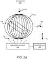
- FIG. 2A there is shown a simplified block diagram of an example apparatus (not claimed) 200 that includes a tumbling cage 202.
- the tumbling cage 202 may be implemented to rotate the 3D printed object 108 in three dimensions and thereby expose each of the sides of the 3D printed object 108 to the radiation source 102.
- the 3D printed object 108 may be attached to the tumbling cage 202 such that the 3D printed object 108 may rotate in conjunction with the tumbling cage 202.
- a first side facing the radiation source 102 may be irradiated with a pulse of radiation 106
- the tumbling cage 202 may be rotated, and a second side facing the radiation source 102 may be irradiated with a pulse of radiation 106.
- This process may be repeated until each of the sides of the 3D printed object 108 has been irradiated.
- the controller 104 may control the position of the tumbling cage 202 such that each of the sides of the 3D printed object 108 may be irradiated.
- the 3D printed object 108 may be inserted into the tumbling cage 202 and may remain unbound to the tumbling cage 202, e.g., the 3D printed object 108 may tumble freely as the tumbling cage 202 is rotated randomly in either or both of the directions shown by the arrows 204 and 206.
- the radiation source 102 may apply radiation 106 onto the 3D printed object 108.
- the controller 104 may control the radiation source 102 to apply the radiation 106 in short pulses or may control the radiation source 102 to apply the radiation 106 over a relatively longer period of time.
- the 3D printed object 108 may be subjected to a sufficiently long exposure such that all of the sides of the 3D printed object 108 may be uniformly irradiated despite the random motion of the tumbling cage 202 and thus, the 3D printed object 108.
- the controller 104 may control application of the radiation 106 based upon, for instance, the materials from which the 3D printed object 108 was formed, the thickness of the 3D printed object 108, etc.
- FIG. 2B there is shown a simplified block diagram of an example apparatus 220 that includes a spherical mirror 222, which may also be referred to as an "integrating sphere".
- the spherical mirror 222 may include reflective surfaces such that radiation 106 emitted from the radiation source 102 may be reflected and applied concurrently on multiple sides of the 3D printed object 108.
- the controller 104 may control the radiation source 102 to apply a pulse of radiation 106.
- the controller 104 may control application of the radiation 106 based upon, for instance, the materials from which the 3D printed object 108 was formed, the thickness of the 3D printed object 108, etc.
- FIG. 2C there is shown a simplified block diagram of an example apparatus (not claimed) 240 that includes a plurality of radiation sources 102 and 242-246.
- the 3D printed object 108 may be positioned between the radiation sources 102, 242-246 such that the sides of the 3D printed object 108 may be irradiated concurrently. That is, the controller 104 may control each of the radiation sources 102, 242-246 to concurrently output radiation 106 onto the multiple sides of the 3D printed object 108.
- the controller 104 may control the radiation sources 102, 242-246 to each apply a pulse of radiation 106.
- controller 104 may control application of the radiation 106 based upon, for instance, the materials from which the 3D printed object 108 was formed, the thickness of the 3D printed object 108, etc.
- the controller 104 may further control each of the radiation sources 102, 242-246 individually to, for instance, apply individual levels of radiation to the sides of the 3D printed object 108.
- a similar type of apparatus that includes a plurality of radiation sources and mirrors that may direct impinging radiation towards a centrally placed 3D printed object 108 may also be used to irradiate the 3D printed object 108.
- FIGS. 3 and 4 depict example methods 300 and 400 for finishing a surface of a 3D printed object 108. It should be apparent to those of ordinary skill in the art that the methods 300 and 400 may represent generalized illustrations and that other operations may be added or existing operations may be removed, modified, or rearranged without departing from the scopes of the methods 300 and 400.
- a 3D object 108 may be printed or otherwise formed.
- the 3D printed object 108 may also include a relatively rough surface as a result of the printing process.
- the 3D printed object 108 may also be placed in an apparatus 100, 200, 220, 240 to be irradiated by a radiation source 102 or multiple radiation sources 102, 242-246.
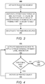
- a radiation source 102 that is to output radiation onto a surface of the 3D printed object 108 at a preset energy level may be activated.
- the controller 104 may control the radiation source 102 to output a pulse of radiation 106, e.g., light and/or heat, onto the surface of the 3D printed object 108.
- the pulse of radiation 106 may be formed of a plurality of sub-pulses, in which the sub-pulses combined have a duration equal to the pulse.
- the controller 104 may wait for a predefined period of time that is sufficient to cause an outer portion of about a predetermined thickness of the surface of the 3D printed object 108 to begin to melt and flow.
- the predefined period of time may be based upon, for instance, the material with which the 3D printed object 108 was formed, the energy level (e.g., temperature, radiation level, etc.) of the radiation applied by the radiation source 102, ambient conditions, etc.
- the energy level at which the radiation is applied and the predefined period of time may be determined through testing of different materials and determined results.
- the radiation source 102 may be deactivated following expiration of the predefined period of time. Accordingly, for instance, the surface of the 3D printed object 108 may be irradiated with a pulse of radiation 106 (and/or sub-pulses of radiation 106) that is sufficient to cause the outer portion of the 3D printed object 108 to begin to melt and flow without causing the inner portion of the 3D printed object 108 from beginning to melt, thus enabling the 3D printed object 108 to maintain its shape.
- a radiation source 102 may be activated to apply a predetermined intensity level irradiation onto a surface of the 3D printed object 108.
- the controller 104 may implement processes similar to those discussed above with respect to the method 300 onto a first surface or side of the 3D printed object 108.
- the controller 104 may determine whether an additional side of the 3D printed object 108 is to be irradiated. In response to a determination that an additional side of the 3D printed object 108 is to be irradiated, the controller 104 may cause the 3D printed object to be rotated with respect to the radiation source 102, as indicated at block 406. In an example in which the 3D printed object 108 is supported on a platform or otherwise mounted on a movable element, the controller 104 may control actuators (not shown) to cause the 3D printed object 108 to be rotated. In another example in which the 3D printed object 108 is placed within a tumbling cage 202, the controller 104 may cause the tumbling cage 202 to be rotated. In a further example, the controller 104 may cause the radiation source 102 to be moved with respect to the 3D printed object 108 such that the radiation source 102 faces another side of the 3D printed object 108.
- blocks 402-406 may be repeated until the controller 104 determines that the 3D printed object 108 contains no further sides to be irradiated. In response to that determination, the method 400 may end as indicated at block 408.
- Some or all of the operations set forth in the methods 300 and 400 may be contained as utilities, programs, or subprograms, in any desired computer accessible medium.
- the methods 300 and 400 may be embodied by computer programs, which may exist in a variety of forms both active and inactive. For example, they may exist as machine readable instructions, including source code, object code, executable code or other formats. Any of the above may be embodied on a non-transitory computer readable storage medium.
- non-transitory computer readable storage media include computer system RAM, ROM, EPROM, EEPROM, and magnetic or optical disks or tapes. It is therefore to be understood that any electronic device capable of executing the above-described functions may perform those functions enumerated above.
- the radiation source 102 is a xenon (Xe) flash lamp
- a sample 3D printed object was irradiated with a single 15 millisecond flash consisting of fifteen equal sub-flashes with varying % duty (% of 15 millisecond period during which the Xe flash lamp was on).
- the use of sub-flashes may allow for more efficient use of the energy stored in the system capacitors.
- the lamp supply voltage and % duty were varied - voltage between 450V and 650V, and % duty between 50% and 70%.
- the lamp setting was calibrated with a bolometer allowing for accurate determination of the total energy impinging upon the sample 3D printed object's surface during a single pulse irradiation.
- Table 1 compares the surface roughness Ra before and after a single 15 millisecond Xe flash exposure for a material PA11 (e.g., Nylon 11 or Polyamide 11) and for a PA12 (Nylon 12 or Polyamide 12).
- PA11 e.g., Nylon 11 or Polyamide 11
- PA12 Nylon 12 or Polyamide 12
- Ra is the arithmetic average of the absolute values of the profile height deviations from the mean line, recorded within the evaluation length.
- Material Color Ra as-is ( ⁇ m) Ra after Xe flash ( ⁇ m) PA11 BLACK 10.434 2.207 PA11 BLACK 13.335 2.156
- PA12 BLACK 8.182 3.429 PA12 BLACK 6.920 3.431
- irradiation induced improvement of the surface roughness may depend on the energy dose delivered during a single flash from the energy source.
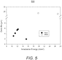
- the energy dose delivered during a single flash from the energy source When the energy is too low, the surface temperature may not rise sufficiently high to melt the thin surface layer of the 3D printed object, whereas, too high of an energy may cause melt convective movement, resulting in a large surface roughness as shown in FIG. 5 .
- the results in Fig. 5 were obtained for a specific irradiation pulse (one 15 millisecond pulse made of 15 equal sub-pulses). The results may likely be different for different pulse conditions.
- FIG. 5 shows a graph 500 depicting an example correlation between the change in the surface roughness of a 3D printed object and irradiation energy applied to the 3D printed object (using a single pulse irradiation as described above).
- Delta Ra is the roughness (Ra) difference between the "as-is” and the irradiated surface.
- the graph 500 also shows results obtained for black and white samples. Samples of each color group have an "as-is" surface roughness characteristics for its color (about 9.9 ⁇ m in case of black samples and about 24.1 ⁇ m in case of white samples). In both cases, the final surface roughness was between 2.2 ⁇ m and 3.4 ⁇ m.
- the graph 500 shows that in this case, the optimum irradiation energy for black samples with original Ra surface roughness of about 10 ⁇ m is at around 13 J/cm 2 .
- the optimum energy for white samples is higher (due to the lower light absorption) and equal about 19 J/cm 2 .
- a lower irradiation energy may be insufficient to liquefy the surface layer, while a higher energy may introduce surface roughness due to uncontrolled movement of the liquefied surface region.
Landscapes
- Engineering & Computer Science (AREA)
- Chemical & Material Sciences (AREA)
- Materials Engineering (AREA)
- Physics & Mathematics (AREA)
- Optics & Photonics (AREA)
- Manufacturing & Machinery (AREA)
- Mechanical Engineering (AREA)
- Plasma & Fusion (AREA)
- Thermal Sciences (AREA)
Claims (9)
- Verfahren zum Fertigstellen eines 3D-gedruckten Objekts in einer Vorrichtung (220), die eine Steuerung (104), eine einzelne Strahlungsquelle (102) und einen kugelförmigen Spiegel (222) umfasst, wobei ein dreidimensionales (3D) gedrucktes Objekt, das mehrere Seiten umfasst, dazu dient innerhalb des kugelförmigen Spiegels (222) platziert zu werden, und wobei die einzelne Strahlungsquelle (102) dazu dient den Strahlungsimpuls innerhalb des kugelförmigen Spiegels (222) anzulegen, um es den mehreren Seiten des 3D-gedruckten Objekts zu ermöglichen, auf eine im Wesentlichen gleichzeitige, homogene und gleichmäßige Weise bestrahlt zu werden, wobei das Verfahren Folgendes umfasst:Aktivieren, durch die Steuerung (104), der einzelnen Strahlungsquelle (102) der Vorrichtung (220), um Strahlung bei einem voreingestellten Energieniveau auf eine Oberfläche des 3D-gedruckten Objekts auszugeben; Warten auf einen vordefinierten Zeitraum, der ausreicht, um zu bewirken, dass ein äußerer Teil einer ungefähren zuvor bestimmten Dicke zwischen ungefähr 20 pm und ungefähr 200 pm der Oberfläche des 3D-gedruckten Objekts zu schmelzen und zu fließen beginnt; undDeaktivieren der einzelnen Strahlungsquelle (102) nach dem vordefinierten Zeitraum, um die Oberfläche des 3D-gedruckten Objekts fertigzustellen.
- Verfahren nach Anspruch 1, wobei der vordefinierte Zeitraum einem Strahlungsimpuls entspricht und wobei das Warten auf den vordefinierten Zeitraum ferner das Warten auf einen vordefinierten Zeitraum umfasst, der nicht ausreicht, um zu bewirken, dass Teile innerhalb des äußeren Teils bei dem voreingestellten Energieniveau der Strahlungsquelle zu schmelzen beginnen.
- Verfahren nach Anspruch 1, wobei das 3D-gedruckte Objekt aus kondensierten Pulverpartikeln ausgebildet wird, wobei das Warten auf den vordefinierten Zeitraum ferner das Warten auf einen vordefinierten Zeitraum umfasst, der ausreicht, um zu bewirken, dass überschüssige Pulverpartikel auf dem 3D-gedruckten Material bei dem voreingestellten Energieniveau der Strahlungsquelle schmelzen und fließen.
- Verfahren nach Anspruch 3, das ferner ein Einstellen des Energieniveaus der Strahlungsquelle auf das voreingestellte Energieniveau umfasst, wobei das voreingestellte Energieniveau zwischen ungefähr 1 J/cm2 bis ungefähr 50 J/cm2 liegt und wobei der vordefinierte Zeitraum zwischen ungefähr 100 Mikrosekunden und ungefähr 100 Millisekunden liegt.
- Verfahren nach Anspruch 1, wobei die einzelne Strahlungsquelle (102) eine Xenonlampe, eine Quarz-Wolfram-Halogenlampe und ein Laser ist.
- Verfahren nach Anspruch 1, wobei die Pulverpartikel Partikel eines Materials sind, das aus Polymer, einem Metall, einer Keramik und einer Mischung aus einem Polymer, einem Metall und einem Keramikmaterial ausgewählt ist.
- Vorrichtung zum Durchführen des Verfahrens nach Anspruch 1, die Folgendes umfasst:eine einzelne Strahlungsquelle (102); eine Steuerung (104), um die einzelne Strahlungsquelle (102) zu steuern, um einen Strahlungsimpuls auf ein dreidimensionales (3D) gedrucktes Objekt anzulegen, das mehrere Seiten umfasst, undeinen kugelförmigen Spiegel (222),wobei das 3D-gedruckte Objekt dazu dient, innerhalb des kugelförmigen Spiegels (222) platziert zu werden, undwobei die Strahlungsquelle (102) dazu dient, den Strahlungsimpuls innerhalb des kugelförmigen Spiegels (222) anzulegen, um es den mehreren Seiten des 3D-gedruckten Objekts zu ermöglichen, auf eine im Wesentlichen gleichzeitige, homogene und gleichmäßige Weise bestrahlt zu werden.
- Vorrichtung nach Anspruch 7, wobei die Steuerung (104) ferner dazu dient, die einzelne Strahlungsquelle (102) zu steuern, um den Strahlungsimpuls bei einem Energieniveau zwischen ungefähr 1 J/cm2 und ungefähr 50 J/cm2 und für eine Zeitdauer, die zwischen ungefähr 100 Mikrosekunden und ungefähr 100 Millisekunden liegt, anzulegen.
- Vorrichtung nach Anspruch 7, wobei die Strahlungsquelle (102) eine Xenonlampe, eine Quarz-Wolfram-Halogenlampe und einen Laser umfasst.
Applications Claiming Priority (1)
| Application Number | Priority Date | Filing Date | Title |
|---|---|---|---|
| PCT/US2016/030941 WO2017192140A1 (en) | 2016-05-05 | 2016-05-05 | Finishing a 3d printed object |
Publications (3)
| Publication Number | Publication Date |
|---|---|
| EP3452268A1 EP3452268A1 (de) | 2019-03-13 |
| EP3452268A4 EP3452268A4 (de) | 2019-11-20 |
| EP3452268B1 true EP3452268B1 (de) | 2021-10-20 |
Family
ID=60203130
Family Applications (1)
| Application Number | Title | Priority Date | Filing Date |
|---|---|---|---|
| EP16901141.8A Not-in-force EP3452268B1 (de) | 2016-05-05 | 2016-05-05 | Endbearbeitung eines 3d-druckgegenstandes |
Country Status (4)
| Country | Link |
|---|---|
| US (1) | US11104069B2 (de) |
| EP (1) | EP3452268B1 (de) |
| CN (1) | CN108602250B (de) |
| WO (1) | WO2017192140A1 (de) |
Families Citing this family (9)
| Publication number | Priority date | Publication date | Assignee | Title |
|---|---|---|---|---|
| EP3589471B1 (de) * | 2017-02-28 | 2023-05-17 | Hewlett-Packard Development Company, L.P. | Strahlungsmengenbestimmung für ein bestimmtes oberflächeneigenschaftsniveau |
| US11498269B2 (en) | 2018-04-30 | 2022-11-15 | Hewlett-Packard Development Company, L.P. | Post-print processing of three dimensional (3D) printed objects |
| CN109049712B (zh) * | 2018-09-10 | 2020-11-06 | 北京易加三维科技有限公司 | 3d打印零件后处理装置及其方法 |
| DE102018216206A1 (de) * | 2018-09-24 | 2020-03-26 | Fraunhofer-Gesellschaft zur Förderung der angewandten Forschung e.V. | Verfahren zum Glätten der Oberfläche eines Kunststoffbauteils |
| DE102019004122A1 (de) * | 2019-06-13 | 2020-12-17 | Loramendi, S.Coop. | Verfahren und Vorrichtung zum Herstellen von 3D-Formteilen durch Schichtaufbautechnik unter Verwendung einer Kernreinigungsstation |
| US11453163B2 (en) | 2019-08-27 | 2022-09-27 | International Business Machines Corporation | Additive manufacturing with magnetic manipulation |
| CN114599761A (zh) * | 2019-10-28 | 2022-06-07 | 3M创新有限公司 | 修整金属表面的系统和方法 |
| US11993023B2 (en) * | 2021-09-23 | 2024-05-28 | International Business Machines Corporation | Three-dimensional part smoothing in reduced gravity |
| WO2024059749A2 (en) * | 2022-09-15 | 2024-03-21 | Align Technology, Inc. | Systems and methods for modifying surfaces of additively manufactured objects |
Family Cites Families (15)
| Publication number | Priority date | Publication date | Assignee | Title |
|---|---|---|---|---|
| IT1119679B (it) | 1979-03-05 | 1986-03-10 | Fiat Auto Spa | Apparecchiatura per effettuare trattamenti su pezzi metallici mediante |
| US6032040A (en) * | 1997-01-24 | 2000-02-29 | Lucent Technologies Inc. | Method and system for autoreconnect of wireless calls |
| CN1086978C (zh) * | 1998-12-29 | 2002-07-03 | 西安交通大学 | 非激光光源线扫描光固化成型方法及其装置 |
| US6504127B1 (en) | 1999-09-30 | 2003-01-07 | National Research Council Of Canada | Laser consolidation methodology and apparatus for manufacturing precise structures |
| ATE489220T1 (de) * | 2002-04-17 | 2010-12-15 | Stratasys Inc | Glättverfahren für geschichtete ablagerungsmodellierung |
| US8653409B1 (en) * | 2004-06-23 | 2014-02-18 | Board Of Governors For Higher Education, State Of Rhode Island And Providence Plantations | Selective surface smoothing using lasers |
| US9415544B2 (en) | 2006-08-29 | 2016-08-16 | 3D Systems, Inc. | Wall smoothness, feature accuracy and resolution in projected images via exposure levels in solid imaging |
| US8506738B2 (en) * | 2007-12-17 | 2013-08-13 | Guardian Industries Corp. | Localized heating via an infrared heat source array of edge seals for a vacuum insulating glass unit, and/or unitized oven with infrared heat source array for accomplishing the same |
| US20090283119A1 (en) * | 2008-05-16 | 2009-11-19 | Khalil Moussa | Post-Processing System For Solid Freeform Fabrication Parts |
| CA2762826C (en) | 2009-05-22 | 2018-03-13 | Mesocoat, Inc. | Article and method of manufacturing related to nanocomposite overlays |
| CN105163922B (zh) | 2012-11-08 | 2018-11-06 | Ddm系统有限责任公司 | 用于制造三维物体的系统和方法 |
| US10315275B2 (en) | 2013-01-24 | 2019-06-11 | Wisconsin Alumni Research Foundation | Reducing surface asperities |
| US20140255666A1 (en) | 2013-03-06 | 2014-09-11 | University Of Louisville Research Foundation, Inc. | Powder Bed Fusion Systems, Apparatus, and Processes for Multi-Material Part Production |
| US9873229B2 (en) | 2013-11-21 | 2018-01-23 | Hankookin, Inc. | Three-dimensional object development |
| GB2521386A (en) | 2013-12-18 | 2015-06-24 | Ibm | Improvements in 3D printing |
-
2016
- 2016-05-05 EP EP16901141.8A patent/EP3452268B1/de not_active Not-in-force
- 2016-05-05 WO PCT/US2016/030941 patent/WO2017192140A1/en not_active Ceased
- 2016-05-05 US US16/072,144 patent/US11104069B2/en active Active
- 2016-05-05 CN CN201680080616.1A patent/CN108602250B/zh not_active Expired - Fee Related
Non-Patent Citations (1)
| Title |
|---|
| None * |
Also Published As
| Publication number | Publication date |
|---|---|
| WO2017192140A1 (en) | 2017-11-09 |
| EP3452268A1 (de) | 2019-03-13 |
| CN108602250B (zh) | 2021-04-16 |
| EP3452268A4 (de) | 2019-11-20 |
| US20190030803A1 (en) | 2019-01-31 |
| CN108602250A (zh) | 2018-09-28 |
| US11104069B2 (en) | 2021-08-31 |
Similar Documents
| Publication | Publication Date | Title |
|---|---|---|
| EP3452268B1 (de) | Endbearbeitung eines 3d-druckgegenstandes | |
| US10981322B2 (en) | Process for the accelerated production of objects by means of generative manufacturing | |
| CN111278627B (zh) | 用于由颗粒形成的3d特征的热支撑物 | |
| US12115733B2 (en) | Unfused thermal support area in 3D fabrication systems | |
| US11148227B2 (en) | Laser melting of build materials | |
| US11840031B2 (en) | Radiation amount determination for an intended surface property level | |
| US20220305734A1 (en) | Recoater operation adjustments based on layer structures | |
| US20210354395A1 (en) | Thermal supports for formation of 3d object portions | |
| US20210331252A1 (en) | Selectively melt micron-sized particles using micro-mirrors | |
| US12441059B2 (en) | Energy emitting apparatuses for build material layers | |
| US20210331402A1 (en) | 3d printing control | |
| US20210197451A1 (en) | Additive manufacturing | |
| US20210229356A1 (en) | Baffles to absorb reflected energy in reflectors | |
| US11745266B2 (en) | Additive manufacturing of metals | |
| US20220040927A1 (en) | Build material layer control | |
| US20220219395A1 (en) | Independently movable carriages carrying respective energy sources |
Legal Events
| Date | Code | Title | Description |
|---|---|---|---|
| STAA | Information on the status of an ep patent application or granted ep patent |
Free format text: STATUS: THE INTERNATIONAL PUBLICATION HAS BEEN MADE |
|
| PUAI | Public reference made under article 153(3) epc to a published international application that has entered the european phase |
Free format text: ORIGINAL CODE: 0009012 |
|
| STAA | Information on the status of an ep patent application or granted ep patent |
Free format text: STATUS: REQUEST FOR EXAMINATION WAS MADE |
|
| 17P | Request for examination filed |
Effective date: 20180723 |
|
| AK | Designated contracting states |
Kind code of ref document: A1 Designated state(s): AL AT BE BG CH CY CZ DE DK EE ES FI FR GB GR HR HU IE IS IT LI LT LU LV MC MK MT NL NO PL PT RO RS SE SI SK SM TR |
|
| AX | Request for extension of the european patent |
Extension state: BA ME |
|
| RAP1 | Party data changed (applicant data changed or rights of an application transferred) |
Owner name: HEWLETT-PACKARD DEVELOPMENT COMPANY, L.P. |
|
| DAV | Request for validation of the european patent (deleted) | ||
| DAX | Request for extension of the european patent (deleted) | ||
| REG | Reference to a national code |
Ref country code: DE Ref legal event code: R079 Ref document number: 602016065291 Country of ref document: DE Free format text: PREVIOUS MAIN CLASS: B29C0067000000 Ipc: B29C0071020000 |
|
| A4 | Supplementary search report drawn up and despatched |
Effective date: 20191021 |
|
| RIC1 | Information provided on ipc code assigned before grant |
Ipc: B33Y 50/02 20150101ALI20191015BHEP Ipc: B33Y 70/00 20150101ALI20191015BHEP Ipc: B29C 67/00 20170101ALI20191015BHEP Ipc: B33Y 10/00 20150101ALI20191015BHEP Ipc: B29C 71/04 20060101ALI20191015BHEP Ipc: B23K 26/352 20140101ALI20191015BHEP Ipc: B33Y 30/00 20150101ALI20191015BHEP Ipc: B23K 26/354 20140101ALI20191015BHEP Ipc: B29C 71/02 20060101AFI20191015BHEP |
|
| STAA | Information on the status of an ep patent application or granted ep patent |
Free format text: STATUS: EXAMINATION IS IN PROGRESS |
|
| 17Q | First examination report despatched |
Effective date: 20200727 |
|
| GRAP | Despatch of communication of intention to grant a patent |
Free format text: ORIGINAL CODE: EPIDOSNIGR1 |
|
| STAA | Information on the status of an ep patent application or granted ep patent |
Free format text: STATUS: GRANT OF PATENT IS INTENDED |
|
| INTG | Intention to grant announced |
Effective date: 20210709 |
|
| GRAS | Grant fee paid |
Free format text: ORIGINAL CODE: EPIDOSNIGR3 |
|
| GRAA | (expected) grant |
Free format text: ORIGINAL CODE: 0009210 |
|
| STAA | Information on the status of an ep patent application or granted ep patent |
Free format text: STATUS: THE PATENT HAS BEEN GRANTED |
|
| AK | Designated contracting states |
Kind code of ref document: B1 Designated state(s): AL AT BE BG CH CY CZ DE DK EE ES FI FR GB GR HR HU IE IS IT LI LT LU LV MC MK MT NL NO PL PT RO RS SE SI SK SM TR |
|
| REG | Reference to a national code |
Ref country code: GB Ref legal event code: FG4D |
|
| REG | Reference to a national code |
Ref country code: CH Ref legal event code: EP |
|
| REG | Reference to a national code |
Ref country code: IE Ref legal event code: FG4D |
|
| REG | Reference to a national code |
Ref country code: DE Ref legal event code: R096 Ref document number: 602016065291 Country of ref document: DE |
|
| REG | Reference to a national code |
Ref country code: AT Ref legal event code: REF Ref document number: 1439593 Country of ref document: AT Kind code of ref document: T Effective date: 20211115 |
|
| REG | Reference to a national code |
Ref country code: LT Ref legal event code: MG9D |
|
| REG | Reference to a national code |
Ref country code: NL Ref legal event code: MP Effective date: 20211020 |
|
| REG | Reference to a national code |
Ref country code: AT Ref legal event code: MK05 Ref document number: 1439593 Country of ref document: AT Kind code of ref document: T Effective date: 20211020 |
|
| PG25 | Lapsed in a contracting state [announced via postgrant information from national office to epo] |
Ref country code: RS Free format text: LAPSE BECAUSE OF FAILURE TO SUBMIT A TRANSLATION OF THE DESCRIPTION OR TO PAY THE FEE WITHIN THE PRESCRIBED TIME-LIMIT Effective date: 20211020 Ref country code: LT Free format text: LAPSE BECAUSE OF FAILURE TO SUBMIT A TRANSLATION OF THE DESCRIPTION OR TO PAY THE FEE WITHIN THE PRESCRIBED TIME-LIMIT Effective date: 20211020 Ref country code: FI Free format text: LAPSE BECAUSE OF FAILURE TO SUBMIT A TRANSLATION OF THE DESCRIPTION OR TO PAY THE FEE WITHIN THE PRESCRIBED TIME-LIMIT Effective date: 20211020 Ref country code: BG Free format text: LAPSE BECAUSE OF FAILURE TO SUBMIT A TRANSLATION OF THE DESCRIPTION OR TO PAY THE FEE WITHIN THE PRESCRIBED TIME-LIMIT Effective date: 20220120 Ref country code: AT Free format text: LAPSE BECAUSE OF FAILURE TO SUBMIT A TRANSLATION OF THE DESCRIPTION OR TO PAY THE FEE WITHIN THE PRESCRIBED TIME-LIMIT Effective date: 20211020 |
|
| PG25 | Lapsed in a contracting state [announced via postgrant information from national office to epo] |
Ref country code: IS Free format text: LAPSE BECAUSE OF FAILURE TO SUBMIT A TRANSLATION OF THE DESCRIPTION OR TO PAY THE FEE WITHIN THE PRESCRIBED TIME-LIMIT Effective date: 20220220 Ref country code: SE Free format text: LAPSE BECAUSE OF FAILURE TO SUBMIT A TRANSLATION OF THE DESCRIPTION OR TO PAY THE FEE WITHIN THE PRESCRIBED TIME-LIMIT Effective date: 20211020 Ref country code: PT Free format text: LAPSE BECAUSE OF FAILURE TO SUBMIT A TRANSLATION OF THE DESCRIPTION OR TO PAY THE FEE WITHIN THE PRESCRIBED TIME-LIMIT Effective date: 20220221 Ref country code: PL Free format text: LAPSE BECAUSE OF FAILURE TO SUBMIT A TRANSLATION OF THE DESCRIPTION OR TO PAY THE FEE WITHIN THE PRESCRIBED TIME-LIMIT Effective date: 20211020 Ref country code: NO Free format text: LAPSE BECAUSE OF FAILURE TO SUBMIT A TRANSLATION OF THE DESCRIPTION OR TO PAY THE FEE WITHIN THE PRESCRIBED TIME-LIMIT Effective date: 20220120 Ref country code: NL Free format text: LAPSE BECAUSE OF FAILURE TO SUBMIT A TRANSLATION OF THE DESCRIPTION OR TO PAY THE FEE WITHIN THE PRESCRIBED TIME-LIMIT Effective date: 20211020 Ref country code: LV Free format text: LAPSE BECAUSE OF FAILURE TO SUBMIT A TRANSLATION OF THE DESCRIPTION OR TO PAY THE FEE WITHIN THE PRESCRIBED TIME-LIMIT Effective date: 20211020 Ref country code: HR Free format text: LAPSE BECAUSE OF FAILURE TO SUBMIT A TRANSLATION OF THE DESCRIPTION OR TO PAY THE FEE WITHIN THE PRESCRIBED TIME-LIMIT Effective date: 20211020 Ref country code: GR Free format text: LAPSE BECAUSE OF FAILURE TO SUBMIT A TRANSLATION OF THE DESCRIPTION OR TO PAY THE FEE WITHIN THE PRESCRIBED TIME-LIMIT Effective date: 20220121 Ref country code: ES Free format text: LAPSE BECAUSE OF FAILURE TO SUBMIT A TRANSLATION OF THE DESCRIPTION OR TO PAY THE FEE WITHIN THE PRESCRIBED TIME-LIMIT Effective date: 20211020 |
|
| REG | Reference to a national code |
Ref country code: DE Ref legal event code: R097 Ref document number: 602016065291 Country of ref document: DE |
|
| PG25 | Lapsed in a contracting state [announced via postgrant information from national office to epo] |
Ref country code: SM Free format text: LAPSE BECAUSE OF FAILURE TO SUBMIT A TRANSLATION OF THE DESCRIPTION OR TO PAY THE FEE WITHIN THE PRESCRIBED TIME-LIMIT Effective date: 20211020 Ref country code: SK Free format text: LAPSE BECAUSE OF FAILURE TO SUBMIT A TRANSLATION OF THE DESCRIPTION OR TO PAY THE FEE WITHIN THE PRESCRIBED TIME-LIMIT Effective date: 20211020 Ref country code: RO Free format text: LAPSE BECAUSE OF FAILURE TO SUBMIT A TRANSLATION OF THE DESCRIPTION OR TO PAY THE FEE WITHIN THE PRESCRIBED TIME-LIMIT Effective date: 20211020 Ref country code: EE Free format text: LAPSE BECAUSE OF FAILURE TO SUBMIT A TRANSLATION OF THE DESCRIPTION OR TO PAY THE FEE WITHIN THE PRESCRIBED TIME-LIMIT Effective date: 20211020 Ref country code: DK Free format text: LAPSE BECAUSE OF FAILURE TO SUBMIT A TRANSLATION OF THE DESCRIPTION OR TO PAY THE FEE WITHIN THE PRESCRIBED TIME-LIMIT Effective date: 20211020 Ref country code: CZ Free format text: LAPSE BECAUSE OF FAILURE TO SUBMIT A TRANSLATION OF THE DESCRIPTION OR TO PAY THE FEE WITHIN THE PRESCRIBED TIME-LIMIT Effective date: 20211020 |
|
| PLBE | No opposition filed within time limit |
Free format text: ORIGINAL CODE: 0009261 |
|
| STAA | Information on the status of an ep patent application or granted ep patent |
Free format text: STATUS: NO OPPOSITION FILED WITHIN TIME LIMIT |
|
| 26N | No opposition filed |
Effective date: 20220721 |
|
| PG25 | Lapsed in a contracting state [announced via postgrant information from national office to epo] |
Ref country code: AL Free format text: LAPSE BECAUSE OF FAILURE TO SUBMIT A TRANSLATION OF THE DESCRIPTION OR TO PAY THE FEE WITHIN THE PRESCRIBED TIME-LIMIT Effective date: 20211020 |
|
| PG25 | Lapsed in a contracting state [announced via postgrant information from national office to epo] |
Ref country code: SI Free format text: LAPSE BECAUSE OF FAILURE TO SUBMIT A TRANSLATION OF THE DESCRIPTION OR TO PAY THE FEE WITHIN THE PRESCRIBED TIME-LIMIT Effective date: 20211020 |
|
| REG | Reference to a national code |
Ref country code: CH Ref legal event code: PL |
|
| REG | Reference to a national code |
Ref country code: BE Ref legal event code: MM Effective date: 20220531 |
|
| PG25 | Lapsed in a contracting state [announced via postgrant information from national office to epo] |
Ref country code: MC Free format text: LAPSE BECAUSE OF FAILURE TO SUBMIT A TRANSLATION OF THE DESCRIPTION OR TO PAY THE FEE WITHIN THE PRESCRIBED TIME-LIMIT Effective date: 20211020 Ref country code: LU Free format text: LAPSE BECAUSE OF NON-PAYMENT OF DUE FEES Effective date: 20220505 Ref country code: LI Free format text: LAPSE BECAUSE OF NON-PAYMENT OF DUE FEES Effective date: 20220531 Ref country code: CH Free format text: LAPSE BECAUSE OF NON-PAYMENT OF DUE FEES Effective date: 20220531 |
|
| PG25 | Lapsed in a contracting state [announced via postgrant information from national office to epo] |
Ref country code: IE Free format text: LAPSE BECAUSE OF NON-PAYMENT OF DUE FEES Effective date: 20220505 |
|
| PG25 | Lapsed in a contracting state [announced via postgrant information from national office to epo] |
Ref country code: IT Free format text: LAPSE BECAUSE OF FAILURE TO SUBMIT A TRANSLATION OF THE DESCRIPTION OR TO PAY THE FEE WITHIN THE PRESCRIBED TIME-LIMIT Effective date: 20211020 Ref country code: BE Free format text: LAPSE BECAUSE OF NON-PAYMENT OF DUE FEES Effective date: 20220531 |
|
| PGFP | Annual fee paid to national office [announced via postgrant information from national office to epo] |
Ref country code: FR Payment date: 20230420 Year of fee payment: 8 Ref country code: DE Payment date: 20230419 Year of fee payment: 8 |
|
| PGFP | Annual fee paid to national office [announced via postgrant information from national office to epo] |
Ref country code: GB Payment date: 20230420 Year of fee payment: 8 |
|
| PG25 | Lapsed in a contracting state [announced via postgrant information from national office to epo] |
Ref country code: HU Free format text: LAPSE BECAUSE OF FAILURE TO SUBMIT A TRANSLATION OF THE DESCRIPTION OR TO PAY THE FEE WITHIN THE PRESCRIBED TIME-LIMIT; INVALID AB INITIO Effective date: 20160505 |
|
| PG25 | Lapsed in a contracting state [announced via postgrant information from national office to epo] |
Ref country code: MK Free format text: LAPSE BECAUSE OF FAILURE TO SUBMIT A TRANSLATION OF THE DESCRIPTION OR TO PAY THE FEE WITHIN THE PRESCRIBED TIME-LIMIT Effective date: 20211020 Ref country code: CY Free format text: LAPSE BECAUSE OF FAILURE TO SUBMIT A TRANSLATION OF THE DESCRIPTION OR TO PAY THE FEE WITHIN THE PRESCRIBED TIME-LIMIT Effective date: 20211020 |
|
| PG25 | Lapsed in a contracting state [announced via postgrant information from national office to epo] |
Ref country code: TR Free format text: LAPSE BECAUSE OF FAILURE TO SUBMIT A TRANSLATION OF THE DESCRIPTION OR TO PAY THE FEE WITHIN THE PRESCRIBED TIME-LIMIT Effective date: 20211020 |
|
| PG25 | Lapsed in a contracting state [announced via postgrant information from national office to epo] |
Ref country code: MT Free format text: LAPSE BECAUSE OF FAILURE TO SUBMIT A TRANSLATION OF THE DESCRIPTION OR TO PAY THE FEE WITHIN THE PRESCRIBED TIME-LIMIT Effective date: 20211020 |
|
| REG | Reference to a national code |
Ref country code: DE Ref legal event code: R119 Ref document number: 602016065291 Country of ref document: DE |
|
| GBPC | Gb: european patent ceased through non-payment of renewal fee |
Effective date: 20240505 |
|
| PG25 | Lapsed in a contracting state [announced via postgrant information from national office to epo] |
Ref country code: DE Free format text: LAPSE BECAUSE OF NON-PAYMENT OF DUE FEES Effective date: 20241203 |
|
| PG25 | Lapsed in a contracting state [announced via postgrant information from national office to epo] |
Ref country code: FR Free format text: LAPSE BECAUSE OF NON-PAYMENT OF DUE FEES Effective date: 20240531 |
|
| PG25 | Lapsed in a contracting state [announced via postgrant information from national office to epo] |
Ref country code: GB Free format text: LAPSE BECAUSE OF NON-PAYMENT OF DUE FEES Effective date: 20240505 |