EP3451982B1 - Perforierter stomabarrierenextender - Google Patents
Perforierter stomabarrierenextender Download PDFInfo
- Publication number
- EP3451982B1 EP3451982B1 EP17723595.9A EP17723595A EP3451982B1 EP 3451982 B1 EP3451982 B1 EP 3451982B1 EP 17723595 A EP17723595 A EP 17723595A EP 3451982 B1 EP3451982 B1 EP 3451982B1
- Authority
- EP
- European Patent Office
- Prior art keywords
- barrier
- ostomy
- extender
- barrier extender
- perforated
- Prior art date
- Legal status (The legal status is an assumption and is not a legal conclusion. Google has not performed a legal analysis and makes no representation as to the accuracy of the status listed.)
- Active
Links
Images


Classifications
-
- A—HUMAN NECESSITIES
- A61—MEDICAL OR VETERINARY SCIENCE; HYGIENE
- A61F—FILTERS IMPLANTABLE INTO BLOOD VESSELS; PROSTHESES; DEVICES PROVIDING PATENCY TO, OR PREVENTING COLLAPSING OF, TUBULAR STRUCTURES OF THE BODY, e.g. STENTS; ORTHOPAEDIC, NURSING OR CONTRACEPTIVE DEVICES; FOMENTATION; TREATMENT OR PROTECTION OF EYES OR EARS; BANDAGES, DRESSINGS OR ABSORBENT PADS; FIRST-AID KITS
- A61F5/00—Orthopaedic methods or devices for non-surgical treatment of bones or joints; Nursing devices ; Anti-rape devices
- A61F5/44—Devices worn by the patient for reception of urine, faeces, catamenial or other discharge; Colostomy devices
- A61F5/445—Colostomy, ileostomy or urethrostomy devices
- A61F5/448—Means for attaching bag to seal ring
-
- A—HUMAN NECESSITIES
- A61—MEDICAL OR VETERINARY SCIENCE; HYGIENE
- A61F—FILTERS IMPLANTABLE INTO BLOOD VESSELS; PROSTHESES; DEVICES PROVIDING PATENCY TO, OR PREVENTING COLLAPSING OF, TUBULAR STRUCTURES OF THE BODY, e.g. STENTS; ORTHOPAEDIC, NURSING OR CONTRACEPTIVE DEVICES; FOMENTATION; TREATMENT OR PROTECTION OF EYES OR EARS; BANDAGES, DRESSINGS OR ABSORBENT PADS; FIRST-AID KITS
- A61F5/00—Orthopaedic methods or devices for non-surgical treatment of bones or joints; Nursing devices ; Anti-rape devices
- A61F5/44—Devices worn by the patient for reception of urine, faeces, catamenial or other discharge; Colostomy devices
- A61F5/4404—Details or parts
-
- A—HUMAN NECESSITIES
- A61—MEDICAL OR VETERINARY SCIENCE; HYGIENE
- A61F—FILTERS IMPLANTABLE INTO BLOOD VESSELS; PROSTHESES; DEVICES PROVIDING PATENCY TO, OR PREVENTING COLLAPSING OF, TUBULAR STRUCTURES OF THE BODY, e.g. STENTS; ORTHOPAEDIC, NURSING OR CONTRACEPTIVE DEVICES; FOMENTATION; TREATMENT OR PROTECTION OF EYES OR EARS; BANDAGES, DRESSINGS OR ABSORBENT PADS; FIRST-AID KITS
- A61F5/00—Orthopaedic methods or devices for non-surgical treatment of bones or joints; Nursing devices ; Anti-rape devices
- A61F5/44—Devices worn by the patient for reception of urine, faeces, catamenial or other discharge; Colostomy devices
- A61F5/443—Devices worn by the patient for reception of urine, faeces, catamenial or other discharge; Colostomy devices having adhesive seals for securing to the body, e.g. of hydrocolloid type seals, e.g. gels, starches, karaya gums
-
- A—HUMAN NECESSITIES
- A61—MEDICAL OR VETERINARY SCIENCE; HYGIENE
- A61F—FILTERS IMPLANTABLE INTO BLOOD VESSELS; PROSTHESES; DEVICES PROVIDING PATENCY TO, OR PREVENTING COLLAPSING OF, TUBULAR STRUCTURES OF THE BODY, e.g. STENTS; ORTHOPAEDIC, NURSING OR CONTRACEPTIVE DEVICES; FOMENTATION; TREATMENT OR PROTECTION OF EYES OR EARS; BANDAGES, DRESSINGS OR ABSORBENT PADS; FIRST-AID KITS
- A61F5/00—Orthopaedic methods or devices for non-surgical treatment of bones or joints; Nursing devices ; Anti-rape devices
- A61F5/44—Devices worn by the patient for reception of urine, faeces, catamenial or other discharge; Colostomy devices
- A61F5/445—Colostomy, ileostomy or urethrostomy devices
Definitions
- the present disclosure relates to ostomy appliances, and more particularly to extenders for ostomy skin barriers (also known as flanges, wafers, barriers.)
- An ostomy appliance is a medical device or prosthetic provided for collecting body waste from a stoma typically created as a result of a surgical procedure to divert a portion of the colon, small intestine, or bladder.
- One type of ostomy appliance is a pouch that is attached to a user around a stoma.
- a faceplate including an inlet opening to receive a stoma is used to attach an ostomy appliance, such as a pouch, to a user.
- the faceplate may include an adhesive skin barrier to seal against the user's peri stomal skin.
- Some ostomates use barrier extenders to layer over a portion of the skin barrier edges for added security.
- Barrier extenders having a curved or semi-circular shaped body are known. For example, a semi-circular shaped skin adhesive tape for layering over an edge of a skin barrier to reduce the risk of leakage and the risk of a faceplate lifting off from user's skin are available in the market.
- the present disclosure provides an improved skin barrier extender according to various embodiments.
- EP2904996 (A1 ) discloses a seal (1) for fitting around a stoma, comprising a single, flexible, adhesive material having a body (3) in the shape of a split ring, having a first face (5) for attaching to a peristomal surface, a second face (7) for attaching to an ostomy appliance, a wall (9) extending from the first face to the second face and providing an outer wall surface (11) and an inner wall surface (13) which defines an aperture for receiving the stoma, and a first end (15) and a second end (17) spaced apart to define an opening which extends from the outer wall surface to the inner wall surface, wherein the single material and oval, split ring shape of the seal causes the seal to be manipulable to fit around the stoma.
- WO0154632 (A1 ) discloses a flange for a medical collecting bag having an aperture allowing bodily fluids or exudates to enter the bag, wherein the flange has an inner rim delimiting the aperture therein, and wherein the flange has a central area encircling the aperture which area has a predetermined weakening line pattern wherein the force needed for removing the bag flange from the skin or a body side member is smaller than the force needed for breaking the weakening lines enables a simple gradual enlargement of the aperture of an ostomy device for adaptation of the aperture to the size of the stoma or for adaptation of the aperture to the size of a wound and a complete removal of the bag flange when substituting the bag.
- WO2011015201 (A1 ) discloses a two-piece ostomy device comprising a base plate (2) for adhering to the skin surrounding a stoma and a releasable collecting bag (3) for collecting output from said stoma.
- the base plate is releasably connectable to the collecting bag via a first annular flange (8) arranged on the base plate and a second annular flange (14) arranged on the collecting bag.
- the ostomy device further comprises a first through-going hole (7) extending through the first annular flange along a first axis and a second through-going hole (13) extending through the second annular flange along a second axis, wherein the ostomy device further comprises a guiding aid (104) for arranging the first and the second annular flange in a guiding configuration, in which the movement is limited relative to each other in one plane being defined by the first and the second axis and in rotation around at least one of the first or the second axis.
- US6875200 (B1 ) discloses bandage for protecting the skin of an infant's stomach surrounding an umbilical cord stump from the irritating effects of medicinal solutions.
- the bandage is substantially flat and has an absorbent upper surface, a substantially nonabsorbent lower surface, and a circular central cutout wherefrom the umbilical cord stump may be extended.
- the bandage has a flap closure portion comprising a bottom flap and an overlapping top flap.
- the top flap has adhesive on its lower surface whereby the top flap maybe attached to the bottom flap.
- the bandage is placed on the infant's stomach with the umbilical cord stump extending therefrom. Then, the lower surface of the top flap is attached to the underlying bottom flap. With the protective bandage in place, a variety of solutions may be applied to the umbilical cord stump without irritating the sensitive skin of the infant's stomach.
- the present disclosure provides an ostomy barrier extender as detailed in claim 1. Advantageous features are provided in dependent claims.
- Ostomy barrier extenders including at least one perforated feature are provided according to various embodiments.
- the ostomy barrier extender is configured to be divided along the at least one perforated feature by a user.
- the perforated feature provides versatility by allowing the barrier extender to be delivered to a user as a frame, which may be used to overlay and circumscribe an ostomy skin barrier around its entire periphery when desired, and also allowing the barrier extender to be divided into pieces of different shapes and sizes by separating the barrier extender along perforated features.
- a barrier extender according to various embodiments of the present disclosure may be used to provide additional security around its entire periphery or at particular leak-prone areas to prevent edge lifting and/or leakage.
- an ostomy barrier extender comprising a skin friendly adhesive layer, a backing layer laminated on one surface of the skin friendly adhesive layer, a release liner laminated on the other surface of the skin friendly adhesive layer, and at least one perforated feature.
- the ostomy barrier extender further includes an outer periphery, an inner periphery and a ring shaped body defined between the outer periphery and the inner periphery. The ostomy barrier extender is configured to separate along the at least one perforated feature.
- the at least one perforated feature may extend through the backing layer, the skin friendly adhesive layer, and the release liner.
- the ostomy barrier extender may include an inner circular periphery and an outer circular periphery to define a circular ring shaped body therebetween, and two perforated lines extending from the inner circular periphery to the outer circular periphery.
- Each of the two perforated lines may extend in a straight line and may be arranged on the ring shaped body at about 180° from each other, in which the ostomy barrier extender may be configured to divide into two half-ring shaped barrier extenders.
- the ostomy barrier extender may have a ring shaped body including a perforated line and a split defined by a gap between two peripheral ends of the ring shaped body.
- the ostomy barrier extender may have a ring shaped body including two perforated lines arranged on the ring shaped body at about 180° from each other, in which a notch may be provide at each end of the perforated lines to facilitate separation of the barrier extender along the perforated lines.
- the ostomy barrier extender may have a ring shaped body including three perforated lines arranged on the circular ring shaped body at about 120° from each other.
- the ostomy barrier extender may have a ring shaped body including four perforated lines arranged on the ring shaped body at about 90° from each other.
- the ostomy barrier extender may include a square inner periphery and a square outer periphery to define a square ring shaped body therebewteen.
- the corners of the inner periphery and the corners of the outer periphery may be rounded.
- the ostomy barrier extender may include two perforated lines arranged on straight leg portions of the square ring shaped body at about 180° from each other.
- the ostomy barrier extender may be configured to divide into two half-square ring shaped barrier extenders by separating the ostomy barrier extender along the two perforated lines.
- the two perforated lines may be arranged at two corners of the ostomy barrier extender about 180° from each other, in which the ostomy barrier extender is configured to divide into two v-shape barrier extenders by separating the ostomy barrier extender along the two perforated lines.
- the ostomy barrier extender has a square ring shaped body may include four perforated lines arranged at each of the four corners about 90° from each other.
- the ostomy barrier extender may be configured to divide into four strip-like barrier extenders having slanted peripheral edges by separating the ostomy barrier extender along the four perforated lines.
- the ostomy barrier extender may include a circular inner periphery and a square outer periphery with rounded corners and a ring shaped body defined therebetween.
- the ostomy barrier extender may include two perforated lines arranged on the body at about 180° from each other, in which the ostomy barrier extender may be configured to divide into two c-shaped barrier extenders by separating the ostomy barrier extender along two perforated lines.
- the ostomy barrier extender includes an oval inner periphery and a square outer periphery having rounded corners.
- the ostomy barrier extender may include a circular inner periphery and an oval outer periphery defining an oval ring shaped body therebetween.
- the ostomy barrier extender may include two perforated lines arranged on the oval ring shaped body at about 180° from each other, in which the ostomy barrier extender may be configured to divide into two c-shaped barrier extenders by separating the ostomy barrier extender along two perforated lines.
- the ostomy barrier extender may include two curved perforated lines arranged on the oval ring shaped body, such that the oval ring shaped body may be changed to a circular ring shaped body including a circular outer periphery by separating the ostomy barrier extender along the two curved perforated lines.
- the ostomy barrier extender may comprise a plurality of barrier extender strips, in which adjacent barrier extender strips are connected by a perforated line provided along a common periphery.
- the ostomy barrier extender may include four straight perforated lines arranged at about 90° from each other and four curved perforated lines, in which the four curved perforated lines define a circular outline together.
- the ostomy barrier extender may be configured to separate along the perforated lines to customize a shape and a size of the ostomy barrier extender.
- the skin friendly adhesive layer may comprise hydrocolloid
- the backing layer may be formed from a thin urethane film.
- the release liner may be provided with a cut line or at least one peel tab to facilitate removal of the release liner.
- the barrier extender 10 generally includes a backing layer 12, an adhesive layer 14, and a release liner 16.
- the barrier extender has a body that may be of various shapes and sizes.
- the barrier extender has a circular ring shaped body 11 including an inner circular periphery 18, an outer circular periphery 20, and a width 22 defined therebetween.
- the barrier extender 10 may include at least one perforated feature, which is configured such that a user may divide at least the backing layer 12 and the adhesive layer 14 of the barrier extender 10 by separating the barrier extender 10 along the at least one perforated feature.
- the at least one perforated feature may extend through the backing layer 12 and an adhesive layer 14, or through all of the layers including the backing layer 12, the adhesive layer 14, and the release liner 16.
- the barrier extender 10 includes two perforated lines 24, 26 extending across the width 22 of the body 11 to facilitate separation of the barrier extender 10 into two pieces as desired by a user.
- the perforated lines 24, 26 may extend through the backing layer 12 and the adhesive layer 14, or extend through the backing layer 12, the adhesive layer 14, and the release liner 16.
- the inner circular periphery 18 and the outer circular periphery 20 of the barrier extender 10 may be concentric circles providing a constant width 22 around the circular ring shaped body 11 of the barrier extender 10.
- a barrier extender may have oval shaped inner or outer peripheries, and a width that varies around the body of the barrier extender.
- the barrier extender 10 may include two perforated lines 24, 26, which are arranged at about 180° from each other. In other embodiments, two perforated lines may be provided at different locations, for example, 30° or 90° from each other, or the barrier extender may include one perforated line or more than two perforated lines, which may be arranged at various locations on the barrier extender.
- the backing layer 12 of the barrier extender 10 may be formed from a suitable material, such as a thin polymeric film.
- the backing layer 12 may be formed from a thin layer of polyurethane film.
- the adhesive layer 14 of the barrier extender 10 may be formed from a suitable skin friendly adhesive.
- the adhesive layer 14 may be formed from a skin barrier material, such as a hydrocolloid formulation, a silicone adhesive or a medical skin grade adhesive.
- the release liner 16 may be formed from a suitable material that may be easily peeled off from the adhesive layer 14.
- the release liner 16 may be formed from a silicone coated paper.
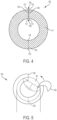
- FIG. 4 is an illustration of an ostomy barrier extender 100 according to an embodiment.
- the barrier extender 100 is constructed similarly to the barrier extender 10 of FIGS. 1-3 , and may have a circular ring shaped body 111.
- the barrier extender 100 includes one perforated line 124 and a split 102 defined by a gap 108 between peripheral edges 104, 106.
- the corners 110, 112, 114, 116 of the peripheral edges 104, 106 may be rounded.
- the barrier extender 100 may include notches 118, 120 at one or both ends of the perforated line 124 to facilitate separation of the barrier extender 100 into two pieces.
- the split 102 may be used to facilitate wrapping and overlaying of the barrier extender 100 around a skin barrier 101 as shown in FIG. 5 .
- the barrier extender 100 may be separated at the perforated line 124 into two arcuate shaped barrier extenders.
- the split 102 and the perforated line 124 are arranged at about 180° from each other.
- the split 102 and the perforated line 124 may be arranged at various locations on the barrier extender 100, at various angles from each other.
- the barrier extender may include one split and more than one perforated lines.
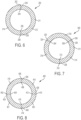
- FIG. 6 is an illustration of an ostomy barrier extender 200 according to another embodiment.
- the barrier extender 200 may be constructed similarly to the barrier extender 10 of FIGS. 1-3 , including a circular ring shaped body 211 and two perforated lines 224, 226, except the barrier extender 200 may include notches 202, 204, 206, 208 at one or both of the ends of the perforated lines 224, 226.
- a user may separate the barrier extender 200 at one of the two perforated lines 224, 226 to facilitate the use of the barrier extender 200 as a circular ring shaped frame to overlay and circumscribe a skin barrier.
- the barrier extender 200 may be separated along both perforated lines 224, 226 and divided into two arcuate shaped barrier extenders 212, 214.
- an ostomy barrier extender 300 for an ostomy appliance may be constructed similarly to the barrier extender 200 of FIG. 6 having a circular ring shaped body 311, except the barrier extender 300 may include three perforated lines 324, 326, 328. One or both of the ends of the perforated lines 324, 326, 328 may be provided with notches 302, 304, 306, 308, 310, 312 to facilitate separation of the barrier extender 300 into three arcuate shaped barrier extenders 314, 316, 318.
- the perforated lines 324, 326, 328 may be arranged at about 120° from each other.
- the perforated lines 324, 326, 328 may be arranged at various locations on the circular ring shaped body 311, for example, less than or greater than 120° from each other.
- FIG. 8 is an illustration of an ostomy barrier extender 400 according to another embodiment.
- the barrier extender 400 may be constructed similarly to the barrier extender 200 of FIG. 6 having a circular ring shaped body 411, except the barrier extender 400 may include four perforated lines 424, 426, 428, 430.
- One or both of the ends of the perforated lines 424, 426, 428, 430 may be provided with notches 402, 404, 406, 408, 410, 412, 414, 416 to facilitate separation of the barrier extender 400 into four arcuate shaped barrier extenders 418, 419, 420, 421.
- the perforated lines 424, 426, 428, 430 are arranged at about 90° from each other.
- the perforated lines 424, 426, 428, 430 may be arranged at various locations on the circular ring shaped body 411, for example, less than or greater than 90° from each other.
- FIGS. 9-12 illustrate ostomy skin barriers of various shapes: an oval shaped skin barrier 2 ( FIG. 9 ), a circular shaped skin barrier 4 ( FIG. 10 ), a triangular shaped skin barrier 6 ( FIG. 11 ), and a square shaped skin barrier 8 ( FIG. 12 ).
- a circular ring shaped ostomy barrier extender including at least one perforated feature, such as the ostomy barrier extender 10, 100, 200, 300, 400 of the forgoing embodiments may be used to overlay and frame around an ostomy skin barrier of various shapes.
- the ostomy barrier extender 10 may be used to overlay and frame around the oval shaped skin barrier 2, the circular shaped skin barrier 4, the triangular shaped skin barrier 6, and the square shaped skin barrier 10 as shown in FIGS. 13-16 .
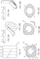
- each of the ostomy barrier extenders 500, 600, 700 may generally include a backing layer, an adhesion layer, a release liner, and at least one perforated feature.
- each of the barrier extenders 500, 600, 700 may include a generally square inner periphery 501, 601, 701 and a generally square outer periphery 503, 603, 703 defining a square ring shaped body 505, 605, 705 therebetween. Corners of the inner and outer peripheries may be rounded.
- the ostomy barrier extender 500 of FIG. 17 may include two perforated lines 502, 504 for facilitating separation of the barrier extender 500 into two pieces. As shown in FIG. 17 , each of the perforated lines 502, 504 may be arranged on a straight leg portion of the square ring shaped body between two corners at about 180° from each other, such that the ostomy barrier extender 500 may be divided into two barrier extenders 506, 508 having a half-rounded square shaped body.
- the ostomy barrier extender 600 of FIG. 18 may include two perforated lines 602, 604. As shown in FIG. 18 , each of the perforated lines 602, 604 may be arranged at diagonal corners of the square ring shaped body, about 180° from each other, such that the barrier extender 600 may be divided into two barrier extenders 606, 608 having a rounded v-shaped body.
- the ostomy barrier extender 700 may include four perforated lines 702, 704, 706, 708. As shown in FIG. 19 , each of the perforated lines 702, 704, 706, 708 may be arranged at each corner of the square ring shaped body about 90° from each other, such that the barrier extender 700 may be divided into four barrier extenders 710, 712, 714, 716 having a strip-like shaped body with slanted ends.
- a square ring shaped ostomy barrier extender including at least one perforated feature may be used to overlay and frame around ostomy skin barriers of various shapes.
- the ostomy barrier extender 500 may be used to overlay and frame around the circular shaped skin barrier 4, the oval shaped skin barrier 2, the triangular shaped skin barrier 6, and the square shaped skin barrier 10 as shown in FIGS. 20-23 .
- FIG. 24 illustrates an ostomy barrier extender 800 according to another embodiment.
- the barrier extender 800 may include a circular inner periphery 802 and a square outer periphery 804 defining a body 803 therebetween, and two perforated lines 814, 816 arrange on straight leg portions of the body 803 at about 180° from each other.
- the corners 806, 808, 810, 812 of the barrier extender 800 may be rounded with a larger radius than the corners of the barrier extender 500 of FIG. 17 , which may further reduce a risk of skin barrier edge lifting.
- ostomy barrier extenders 900, 950 having an oval ring shaped body according to embodiments are shown.
- the ostomy barrier extenders 900, 950 may include a circular inner periphery 902, 952 and an oval outer periphery 904, 954 defining an oval ring shaped body 903, 953 therebetween.
- the oval ring shaped barrier extenders 900, 952 may provide additional protection at 3 o'clock and 9 o'clock positions of a skin barrier.
- the ostomy barrier extender 900 as shown in FIG. 25 may include two perforated lines 906, 908 arranged on narrower portions of the oval shaped body 903 at about 180° from each other. When separated along the perforated lines 906, 908, the ostomy barrier extender 900 may divide into two c-shaped barrier extenders. In other embodiment, the barrier extender 900 may include more than two perforated lines, and the perforated lines may be arranged at various locations on the ostomy barrier extender 900.
- the ostomy barrier extender 950 may include two curved perforated lines 956, 958 arranged such that the oval ring shaped barrier extender 950 may be used as a circular ring shaped barrier extender after removing outer peripheral portions by separating the barrier extender 950 along the perforated lines 956, 958.
- An oval ring shaped ostomy barrier extender including at least one perforated feature may be used to overlay and frame around an ostomy skin barrier of various shapes.
- the ostomy barrier extender 900 may be used to overlay and frame around the circular shaped skin barrier 4, the oval shaped skin barrier 2, the triangular shaped skin barrier 6, and the square shaped skin barrier 10 as shown in FIGS. 27-30 .
- each of the ostomy barrier extender strips 750, 760, 770 may generally include a backing layer, an adhesion layer, a release liner, and at least one perforated feature.
- the barrier extender strip 750 is connected to an adjacent barrier extender strip 752 via a perforated line 751 extending lengthwise along a common periphery between the barrier extender strip 750 and the barrier extender strip 752.
- a barrier extender 758 includes four barrier extender strips 750, 752, 754, 756 and a perforation line 751, 753, 755 between adjacent barrier strips.
- a barrier extender may include less than four or more than four barrier extender strips connected via perforation lines.
- FIGS. 32A and 33A illustrate a barrier extender strip 760, 770, which is connected to adjacent barrier extender strips 762, 764, 772, 774 via perforation lines 761, 763, 771, 773 extending widthwise along a common periphery between adjacent barrier extender strips.
- the barrier extender strip 760 may be provided in a roll form as shown in FIG. 32B or in a folded form as shown in FIG. 33B .
- FIGS. 34A-34C illustrate an ostomy barrier extender 850 according to an embodiment.
- the barrier extender 850 may include a circular inner periphery 852 and a square outer periphery 854 defining a body 853 therebetween.
- the corners 856, 858, 860, 862 of the barrier extender 850 may be rounded.
- the barrier extender 850 may comprise eight perforated lines including four straight perforated lines 864, 866, 868, 870 arranged on straight leg portions of the body 853 at about 90° from each other, and four curved perforated lines 872, 874, 876, 878, each of which extend from an outer periphery proximate a straight perforated line to an outer periphery proximate an adjacent straight perforated line, such that the four curved perforated lines 872, 874, 876, 878 form a circular outline together.
- the barrier extender 850 is configured to allow a user to choose and change the shape of the barrier extender according to need. For example, a user may remove outer peripheral portions of the barrier extender 850 by separating the barrier extender 850 along two curved perforated lines 872, 876, and use the remaining barrier extender to provide added security around 3 o'clock and 9 o'clock positions of an ostomy skin barrier as shown in FIG. 34C . Alternatively, a user may choose to separate the barrier extender 850 along all four curved perforated lines 872, 874, 876, 878 to make a circular ring shaped barrier extender. The plurality of perforated lines allows a user to customize the shape and size of a barrier extender according to need.
- an ostomy barrier extender may be provided with a means to facilitate removal of a release liner.
- the ostomy barrier extender 10 of FIGS. 1-3 may be provided with a curved cut line 28 having a slanted S shape on the release liner 16 extending from the inner periphery 18 to the outer periphery 20 as shown in FIG. 35A .
- the area of the release liner 16 proximate the curved cut line 28 may be provided in a different color than the rest of the release liner 16 for easy identification of the curved cut line 28.
- the curved cut line 28 is configured such that when the barrier extender 10 is folded about a center line 30 as shown in FIG. 35B , two peel tabs 32, 34 may be provided by the release liner 16 to facilitate removal of the release liner 16.
- a barrier extender may be provided with folded peel tabs 40, 42, which protrude away from the surface of a release liner 16 as shown in FIG. 36 . At least some portion of the peel tabs 40, 42 may be colored with a different color than the rest of the release liner 16 for easy identification.
- a barrier extender may be provided with peel tabs 50, 52, which extend beyond an outer periphery of a release liner 16 to facilitate removal of the release liner 16 as shown in FIGS. 37A and 37B . At least some portion of the peel tabs 50, 52 may be colored in a different color than the rest of the release liner 16.
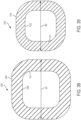
- FIGS. 38 and 39 show differently sized barrier extenders 1000, 1100, according to an embodiment described herein.
- the barrier extenders are shown as blanks, or non-perforated.
- the barrier extender 1000 has a generally square inner periphery 1002, a generally square outer periphery 1004, and a ring shaped body 1011 defined therebetween.
- the barrier extender 1000 has a first width W1.
- the first width W1 may be about 16.5 cm (6.5 inches), but is not limited thereto. Corners of the square peripheries may be rounded.
- the barrier extender 1100 has a generally square inner periphery 1102, a generally square outer periphery 1104, and a ring shaped body 1111 defined therebetween.
- the barrier extender 1100 has a second width W2.
- the second width W2 may be about 13.9 cm (5.5 inches), but is not limited thereto.
- the barrier extenders 1000, 1100 shown in FIGS. 38 and 39 may be manufactured having different sizes. As such, in the embodiments described herein, the barrier extender may be manufactured in different sizes to overlay differently sized or shaped ostomy skin barriers.
- FIG. 40 is a schematic illustration of the ring shaped ostomy barrier extender 1000 of FIG. 38 overlaying a square shaped ostomy skin barrier 1050 having a first size according to an embodiment.
- FIG. 41 is a schematic illustration of the ring shaped ostomy barrier extender 1100 of FIG. 39 overlaying a square shaped ostomy skin barrier 1150 having a second size, less than the first size, according to an embodiment.
- the barrier extender 1100 is applied at a rotationally offset angle relative to the ostomy skin barrier 1150. For example, in one embodiment, the barrier extender 1100 is rotated approximately 45 degrees relative to the skin barrier 1150.
- FIGS. 43-45 show examples of different perforation lines that may be formed in the ostomy barrier extender 1000, 1100, according to embodiments described herein.
- the ostomy barrier extender 1000, 1100 may include four perforated lines 1024, 1026, 1028, 1030.
- the perforated lines 1024, 1026, 1028, 1030 may extend from the inner periphery 1002, 1102 to the outer periphery 1004, 1104.
- the perforated lines 1024, 1026, 1028, 1030 may be formed on respective sides 1032, 1034, 1036, 1038 of the ostomy barrier extender 1000, 1100.
- the perforated lines 1024, 1026, 1028, 1030 may be formed on respective corners 1040, 1042, 1044, 1046. In other embodiments, the perforated lines may be formed at various combinations of the sides and corners.
- the ostomy barrier extender 1000, 1100 includes a perforated line 1024 and a split 1048 defined by a gap extending between the inner periphery 1002 and the outer periphery 1004.
- the split 1048 and the perforated line 1024 may be positioned approximately 180 degrees from one another, but the present disclosure is not limited such relative positioning.
- the split 1048 and the perforated line 1024 may be formed on opposite sides of the ostomy barrier extender 1000, 1100. However, it is understood that the split 1048 and the perforated line 1024 may be formed on the same side, adjacent sides, opposing corners, adjacent corners or on combinations of the sides and corners.
- FIGS. 43-45 are shown with respect to ostomy barrier extenders 1000, 1100 having substantially square outer peripheries and substantially square inner peripheries, the perforated lines may be used on any of the other barrier extenders described herein. It is also understood that additional or fewer perforated lines may be used, and the locations of the perforated lines may vary.
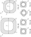
- FIGS. 46 and 47 show differently sized barrier extenders 1200, 1300, according to an embodiment described herein.
- the barrier extenders are shown as blanks, or non-perforated.
- the barrier extender 1200 has a generally circular inner periphery 1202, a generally square outer periphery 1204, and a ring shaped body 1211 defined therebetween.
- the barrier extender 1200 has a first width W1.
- the first width W1 may be about 16.5 cm (6.5 inches), but is not limited thereto.
- the barrier extender 1300 has a generally circular inner periphery 1302, a generally square outer periphery 1304, and a ring shaped body 1311 defined therebetween.
- the barrier extender 1300 has a second width W2.
- the second width W2 may be about 13.9 cm (5.5 inches), but is not limited thereto.
- the barrier extenders 1200, 1300 shown in FIGS. 46 and 47 may be manufactured having different sizes. As such, in the embodiments described herein, the barrier extender may be manufactured in different sizes to overlay differently sized or shaped ostomy skin barriers.
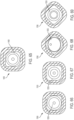
- FIGS. 48-51 are schematic illustrations showing examples of the ostomy barrier extender 1200 (or 1300) overlaying different ostomy skin barriers, according to embodiments described herein.
- FIG. 48 shows the ostomy barrier extender 1200 overlaying the square shaped ostomy skin barrier 8 of FIG. 12 .
- FIG. 49 shows the ostomy barrier extender 1200 overlaying the triangular shaped ostomy skin barrier 6 of FIG. 11 .
- FIG. 50 shows the ostomy barrier extender 1200 overlaying the oval shaped ostomy skin barrier 2 of FIG. 9 .
- FIG. 51 shows the ostomy barrier extender 1200 overlaying the circular shaped ostomy skin barrier 4 of FIG. 10 .
- FIG. 48 shows the ostomy barrier extender 1200 overlaying the square shaped ostomy skin barrier 8 of FIG. 12 .
- FIG. 49 shows the ostomy barrier extender 1200 overlaying the triangular shaped ostomy skin barrier 6 of
- the ostomy barrier extender 1200 may be rotated relative to the ostomy skin barrier before application, to extend coverage over various portions of the ostomy skin barrier depending on a shape of the ostomy skin barrier. It is understood that ostomy barrier extender 1300 may overlay ostomy skin barriers in a similar manner.
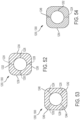
- FIGS. 52-54 show examples of different perforation lines that may be formed in the ostomy barrier extender 1200, 1300, according to embodiments described herein.
- the ostomy barrier extender 1200, 1300 may include four perforated lines 1224, 1226, 1228, 1230.
- the perforated lines 1224, 1226, 1228, 1230 may extend from the inner periphery 1202, 1302 to the outer periphery 1204, 1304.
- the perforated lines 1224, 1226, 1228, 1230 may be formed on respective sides 1232, 1234, 1236, 1238 of the ostomy barrier extender 1200, 1300.
- the perforated lines 1224, 1226, 1228, 1230 may be formed on respective corners 1240, 1242, 1244, 1246. In other embodiments, the perforated lines may be formed at various combinations of the sides and corners.
- the ostomy barrier extender 1200, 1300 includes a perforated line 1224 and a split 1248 defined by a gap extending between the inner periphery 1202 and the outer periphery 1204.
- the split 1248 and the perforated line 1224 may be positioned approximately 180 degrees from one another, but the present disclosure is not limited such relative positioning.
- the split 1248 and the perforated line 1224 may be formed on opposite sides of the ostomy barrier extender 1200, 1300. However, it is understood that the split 1248 and the perforated line 1224 may be formed on the same side, adjacent sides, opposing corners, adjacent corners or on combinations of the sides and corners.
- FIG. 55 is a schematic illustration of the ring shaped ostomy barrier extender 1200 having a circular inner periphery of FIG. 46 overlaying a square shaped ostomy skin barrier 1250 having a first size according to an embodiment.
- FIG. 56 is a schematic illustration of the ring shaped ostomy barrier extender 1300 having a circular inner periphery of FIG. 47 overlaying a square shaped ostomy skin barrier 1350 having a second size, less than the first size, according to an embodiment.
- FIG. 57 is a schematic illustration of the ring shaped ostomy barrier extender 1300 having a circular inner periphery of FIG. 47 overlaying a square shaped ostomy skin barrier 1350 according to an embodiment.
- FIG. 56 is a schematic illustration of the ring shaped ostomy barrier extender 1300 having a circular inner periphery of FIG. 47 overlaying a square shaped ostomy skin barrier 1350 according to an embodiment.
- the ostomy barrier extender 1300 is applied at a rotational angle different from that shown in FIG. 56 .
- the barrier extender 1300 is also applied at a rotationally offset angle.
- the barrier extender 1300 is rotated approximately 45 degrees relative to the skin barrier 1350.
- the ostomy skin barrier 1350 may be oval in shape.
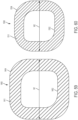
- FIGS. 59 and 60 show differently sized barrier extenders 1400, 1500, according to an embodiment described herein.
- the barrier extenders are shown as blanks, or non-perforated.
- the barrier extender 1400 has a generally oval inner periphery 1402, a generally square outer periphery 1404, and a ring shaped body 1411 defined therebetween.
- the barrier extender 1400 has a first width W1.
- the first width W1 may be about 16.5 cm (6.5 inches), but is not limited thereto.
- the barrier extender 1500 has a generally oval inner periphery 1502, a generally square outer periphery 1504, and a ring shaped body 1511 defined therebetween.
- the barrier extender 1500 has a second width W2.
- the second width W2 may be about 13.9 cm (5.5 inches), but is not limited thereto.
- the barrier extenders 1400, 1500 shown in FIGS. 59 and 60 may be manufactured having different sizes. As such, in the embodiments described herein, the barrier extender may be manufactured in different sizes to overlay differently sized or shaped ostomy skin barriers.
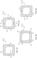
- FIGS. 61-64 show examples of different perforation lines that may be formed in the ostomy barrier extender 1400, 1500, according to embodiments described herein.
- the ostomy barrier extender 1400, 1500 may include two perforated lines 1424, 1426.
- the perforated lines 1424, 1426 may be formed on opposite sides of the of the ostomy barrier extender 1400, 1500 and extend from the inner periphery 1402, 1502 to the outer periphery 1404, 1504.
- the present disclosure is not limited to such a configuration.
- the perforated lines 1424, 1426 may be formed on adjacent sides, opposite or adjacent corners, or combinations of a side and a corner.
- the ostomy barrier extender 1400, 1500 may include four perforated lines 1424, 1426, 1428, 1430.
- the perforated lines 1424, 1426, 1428, 1430 may extend from the inner periphery 1402, 1502 to the outer periphery 1404, 1504.
- the perforated lines 1424, 1426, 1428, 1430 may be formed on respective sides 1432, 1434, 1436, 1438 of the ostomy barrier extender 1400, 1500.
- the perforated lines 1424, 1426, 1428, 1430 may be formed on respective corners 1440, 1442, 1444, 1446.
- the perforated lines may be formed at various combinations of the sides and corners.
- the ostomy barrier extender 1400, 1500 includes a perforated line 1424 and a split 1448 defined by a gap extending between the inner periphery 1402 and the outer periphery 1404.
- the split 1448 and the perforated line 1424 may be positioned approximately 180 degrees from one another, but the present disclosure is not limited such relative positioning.
- the split 1448 and the perforated line 1424 may be formed on opposite sides of the ostomy barrier extender 1400, 1500. However, it is understood that the split 1448 and the perforated line 1424 may be formed on the same side, adjacent sides, opposing corners, adjacent corners or on combinations of the sides and corners.
- FIG. 65 is a schematic illustration of the ring shaped ostomy barrier extender 1400 having an oval inner periphery of FIG. 59 overlaying a square shaped ostomy skin barrier 1450 having a first size according to an embodiment.
- FIG. 66 is a schematic illustration of the ring shaped ostomy barrier extender 1500 having an oval inner periphery of FIG. 60 overlaying a square shaped ostomy skin barrier 1550 having a second size, less than the first size, according to an embodiment.
- FIG. 67 is a schematic illustration of the ring shaped ostomy barrier extender 1500 having an oval inner periphery of FIG. 60 overlaying another square shaped ostomy skin barrier 1550 according to an embodiment.
- FIG. 65 is a schematic illustration of the ring shaped ostomy barrier extender 1400 having an oval inner periphery of FIG. 59 overlaying a square shaped ostomy skin barrier 1450 having a first size according to an embodiment.
- the barrier extender 1500 is applied at a rotationally offset angle relative to an oval skin barrier 1550, and when compared to the position of the ostomy barrier extender 1500 shown in FIGS. 66 and 67 .
- the barrier extender 1500 is rotated approximately 45 degrees relative to the oval skin barrier 1550.
- FIG. 69 shows the barrier extender applied at the rotationally offset angle described with respect to FIG. 68 , on another oval skin barrier 1550, according to an embodiment described herein.
- differently shaped ostomy barrier extenders i.e., ostomy barrier extenders having differently shaped inner peripheries and/or outer peripheries may be used to provide different areas of coverage with different ostomy skin barriers.
Landscapes
- Health & Medical Sciences (AREA)
- Heart & Thoracic Surgery (AREA)
- Life Sciences & Earth Sciences (AREA)
- Epidemiology (AREA)
- Nursing (AREA)
- Orthopedic Medicine & Surgery (AREA)
- Engineering & Computer Science (AREA)
- Veterinary Medicine (AREA)
- Biomedical Technology (AREA)
- Vascular Medicine (AREA)
- Public Health (AREA)
- Animal Behavior & Ethology (AREA)
- General Health & Medical Sciences (AREA)
- Chemical & Material Sciences (AREA)
- Dispersion Chemistry (AREA)
- Orthopedics, Nursing, And Contraception (AREA)
- Materials For Medical Uses (AREA)
Claims (12)
- Ostomiebarriereverlängerer (10), umfassend:eine hautfreundliche Klebeschicht (14);eine Trägerschicht (12), die auf eine Oberfläche der hautfreundlichen Klebeschicht (14) laminiert ist;ein Ablöseträgerband (16), das auf eine gegenüberliegende Oberfläche der hautfreundlichen Klebeschicht (14) laminiert ist;mindestens ein perforiertes Merkmal;einen Außenumfang (20);einen Innenumfang (18) undeinen ringförmigen Körper (11), der zwischen dem Außenumfang (20) und dem Innenumfang (18) definiert ist,wobei der Ostomiebarriereverlängerer (10) dazu konfiguriert ist, entlang mindestens eines perforierten Merkmals getrennt zu werden,dadurch gekennzeichnet, dass das mindestens eine perforierte Merkmal mindestens eine perforierte Linie ist, die sich von dem Innenumfang (18) zu dem Außenumfang (20) erstreckt, und wobei sich das mindestens eine perforierte Merkmal durch die Trägerschicht (12), die hautfreundliche Klebeschicht (14) und die Ablöseschicht (16) erstreckt.
- Ostomiebarriereverlängerer (10) nach Anspruch 1, wobei das perforierte Merkmal mindestens eine perforierte Linie (24) ist, ferner umfassend einen Schlitz (102), der durch eine Lücke (108) zwischen zwei Enden des ringförmigen Körpers (11) definiert ist.
- Ostomiebarriereverlängerer (10) nach Anspruch 1, wobei das mindestens eine perforierte Merkmal mindestens zwei perforierte Linien (24, 26) ist, wobei sich jede perforierte Linie von dem Innenumfang (18) zu dem Außenumfang (20) erstreckt.
- Ostomiebarriereverlängerer (10) nach Anspruch 1, wobei das mindestens eine perforierte Merkmal mindestens vier perforierte Linien (702, 704, 706, 708) ist, wobei sich jede perforierte Linie von dem Innenumfang (18) zu dem Außenumfang (20) erstreckt.
- Ostomiebarriereverlängerer (10) nach Anspruch 2, wobei sich die perforierte Linie (24) und der Schlitz (102) auf dem ringförmigen Körper (11) bei etwa 180 Grad voneinander erstrecken.
- Ostomiebarriereverlängerer (10) nach Anspruch 3, wobei sich zwei perforierte Linien (24, 26) auf dem ringförmigen Körper bei etwa 180 Grad voneinander erstrecken.
- Ostomiebarriereverlängerer (10) nach Anspruch 4, wobei sich vier perforierte Linien (702, 704, 706, 708) auf dem ringförmigen Körper (11) bei etwa 90 Grad voneinander erstrecken.
- Ostomiebarriereverlängerer (10) nach einem der Ansprüche 1 bis 7, wobei der Außenumfang (503, 603, 703) quadratisch ist und der Innenumfang (501, 601, 701) quadratisch ist und die Quadrate abgerundete Ecken aufweisen.
- Ostomiebarriereverlängerer (10) nach einem der Ansprüche 1 bis 7, wobei der Außenumfang (804) quadratisch ist und der Innenumfang (803) kreisförmig ist und das Quadrat abgerundete Ecken aufweist.
- Ostomiebarriereverlängerer (10) nach einem der Ansprüche 1 bis 7, wobei der Außenumfang (1404) quadratisch ist und der Innenumfang (1402) oval ist und das Quadrat abgerundete Ecken aufweist.
- Ostomiebarriereverlängerer (10) nach einem der Ansprüche 1 bis 10, wobei die hautfreundliche Klebeschicht (14) Hydrokolloid umfasst.
- Ostomiebarriereverlängerer (10) nach einem der Ansprüche 1 bis 11, wobei die Trägerschicht (12) aus einem dünnen Urethanfilm gebildet ist.
Priority Applications (1)
| Application Number | Priority Date | Filing Date | Title |
|---|---|---|---|
| EP24158106.5A EP4382081A3 (de) | 2016-05-03 | 2017-05-03 | Perforiertes ostomiebarrierenextender |
Applications Claiming Priority (2)
| Application Number | Priority Date | Filing Date | Title |
|---|---|---|---|
| US201662331119P | 2016-05-03 | 2016-05-03 | |
| PCT/US2017/030761 WO2017192669A1 (en) | 2016-05-03 | 2017-05-03 | Perforated ostomy barrier extender |
Related Child Applications (2)
| Application Number | Title | Priority Date | Filing Date |
|---|---|---|---|
| EP24158106.5A Division EP4382081A3 (de) | 2016-05-03 | 2017-05-03 | Perforiertes ostomiebarrierenextender |
| EP24158106.5A Division-Into EP4382081A3 (de) | 2016-05-03 | 2017-05-03 | Perforiertes ostomiebarrierenextender |
Publications (2)
| Publication Number | Publication Date |
|---|---|
| EP3451982A1 EP3451982A1 (de) | 2019-03-13 |
| EP3451982B1 true EP3451982B1 (de) | 2024-04-17 |
Family
ID=58708046
Family Applications (2)
| Application Number | Title | Priority Date | Filing Date |
|---|---|---|---|
| EP24158106.5A Pending EP4382081A3 (de) | 2016-05-03 | 2017-05-03 | Perforiertes ostomiebarrierenextender |
| EP17723595.9A Active EP3451982B1 (de) | 2016-05-03 | 2017-05-03 | Perforierter stomabarrierenextender |
Family Applications Before (1)
| Application Number | Title | Priority Date | Filing Date |
|---|---|---|---|
| EP24158106.5A Pending EP4382081A3 (de) | 2016-05-03 | 2017-05-03 | Perforiertes ostomiebarrierenextender |
Country Status (8)
| Country | Link |
|---|---|
| US (1) | US11351055B2 (de) |
| EP (2) | EP4382081A3 (de) |
| AU (1) | AU2017260321B2 (de) |
| CA (1) | CA3022593C (de) |
| DK (1) | DK3451982T3 (de) |
| HU (1) | HUE067425T2 (de) |
| LT (1) | LT3451982T (de) |
| WO (1) | WO2017192669A1 (de) |
Families Citing this family (12)
| Publication number | Priority date | Publication date | Assignee | Title |
|---|---|---|---|---|
| BR112018007554A2 (pt) | 2015-10-14 | 2018-10-23 | Convatec Technologies Inc | dispositivo médico com sistema de abertura |
| CN111601545B (zh) | 2017-11-09 | 2024-05-07 | 康沃特克科技公司 | 造口术监测系统和方法 |
| USD893514S1 (en) | 2018-11-08 | 2020-08-18 | 11 Health And Technologies Limited | Display screen or portion thereof with graphical user interface |
| CN114072110B (zh) | 2019-04-25 | 2024-03-08 | 康沃特克科技公司 | 穿孔腔室造口术薄片、包括穿孔腔室造口术薄片的造口术装置以及施加方法 |
| US20220331143A1 (en) * | 2021-04-19 | 2022-10-20 | Racquel Barker | Fecal Collection Assembly |
| US20220096262A1 (en) * | 2020-09-30 | 2022-03-31 | The Curators Of The University Of Missouri | Advanced ileostomy support system |
| EP4228563A1 (de) | 2020-10-15 | 2023-08-23 | ConvaTec Technologies Inc. | Stomasysteme und -verfahren |
| EP4267054B1 (de) | 2020-12-23 | 2025-05-07 | Coloplast A/S | Haftendes stomaproduktsicherungselement |
| USD1081789S1 (en) * | 2022-04-07 | 2025-07-01 | Edward L. Protzeller | Curved masking tape |
| US20250352385A1 (en) * | 2022-11-14 | 2025-11-20 | Hollister Incorporated | Ostomy barrier release liner system |
| US20240307211A1 (en) * | 2023-03-14 | 2024-09-19 | Brett L. Dunbar | Sealing device for ostomy bags |
| WO2025006853A1 (en) * | 2023-06-28 | 2025-01-02 | Hollister Incorporated | Release liners for ostomy leakage sensing accessory |
Citations (1)
| Publication number | Priority date | Publication date | Assignee | Title |
|---|---|---|---|---|
| WO2015052092A1 (en) * | 2013-10-07 | 2015-04-16 | Welland Medical Limited | Support film |
Family Cites Families (9)
| Publication number | Priority date | Publication date | Assignee | Title |
|---|---|---|---|---|
| US5203806A (en) * | 1989-08-02 | 1993-04-20 | Marna Broida | Absorbent pad for medical use |
| DK1250111T3 (da) * | 2000-01-28 | 2006-08-21 | Coloplast As | Opsamlingspose |
| US6875200B1 (en) | 2003-01-10 | 2005-04-05 | Olubunmi J. Ajagbe | Bandage for protection of skin surrounding an umbilical cord stump |
| GB2397230B (en) * | 2003-01-16 | 2006-08-23 | Clinimed | A support for an ostomy bag |
| WO2009000273A1 (en) * | 2007-06-25 | 2008-12-31 | Coloplast A/S | An ostomy appliance with multiple release liners |
| DE102008004175B3 (de) * | 2008-01-11 | 2009-09-24 | Hartmut Redlich | Vorrichtung und Verfahren zur Unterstützung des Verbindens eines Auffangbeutels mit einem Stomaverschluß |
| RU2529475C2 (ru) * | 2009-08-04 | 2014-09-27 | Колопласт А/С | Двухкомпонентное устройство для ухода за стомой с направляющим вспомогательным средством для соединения |
| GB2522416B (en) * | 2014-01-22 | 2020-07-22 | Welland Medical Ltd | Flange extender comprising honey |
| GB201402289D0 (en) * | 2014-02-11 | 2014-03-26 | T G Eakin Ltd | Seal for use with a stoma |
-
2017
- 2017-05-03 LT LTEPPCT/US2017/030761T patent/LT3451982T/lt unknown
- 2017-05-03 WO PCT/US2017/030761 patent/WO2017192669A1/en not_active Ceased
- 2017-05-03 CA CA3022593A patent/CA3022593C/en active Active
- 2017-05-03 EP EP24158106.5A patent/EP4382081A3/de active Pending
- 2017-05-03 HU HUE17723595A patent/HUE067425T2/hu unknown
- 2017-05-03 EP EP17723595.9A patent/EP3451982B1/de active Active
- 2017-05-03 DK DK17723595.9T patent/DK3451982T3/da active
- 2017-05-03 AU AU2017260321A patent/AU2017260321B2/en active Active
- 2017-05-03 US US16/094,132 patent/US11351055B2/en active Active
Patent Citations (1)
| Publication number | Priority date | Publication date | Assignee | Title |
|---|---|---|---|---|
| WO2015052092A1 (en) * | 2013-10-07 | 2015-04-16 | Welland Medical Limited | Support film |
Also Published As
| Publication number | Publication date |
|---|---|
| CA3022593C (en) | 2023-01-10 |
| AU2017260321B2 (en) | 2022-03-17 |
| EP4382081A2 (de) | 2024-06-12 |
| LT3451982T (lt) | 2024-05-10 |
| EP3451982A1 (de) | 2019-03-13 |
| CA3022593A1 (en) | 2017-11-09 |
| WO2017192669A1 (en) | 2017-11-09 |
| HUE067425T2 (hu) | 2024-10-28 |
| EP4382081A3 (de) | 2024-08-07 |
| US11351055B2 (en) | 2022-06-07 |
| DK3451982T3 (da) | 2024-04-29 |
| US20190125570A1 (en) | 2019-05-02 |
| AU2017260321A1 (en) | 2018-11-22 |
Similar Documents
| Publication | Publication Date | Title |
|---|---|---|
| EP3451982B1 (de) | Perforierter stomabarrierenextender | |
| JP6731496B2 (ja) | オストミーパウチのための多ペタル装着部材 | |
| EP2554142B1 (de) | Stomaanwendung mit integrierten Gurtschlaufen | |
| US4890608A (en) | Attachment assembly for use on the human skin | |
| US6814720B2 (en) | Collecting bag | |
| EP2076311B1 (de) | Hülse | |
| EP0146367B1 (de) | Ostomievorrichtung | |
| US20080190528A1 (en) | Disposable flexible cover for hospital remote control unit | |
| BR112012002517B1 (pt) | dispositivo de ostomia de duas peças com ajuda orientadora para acoplamento | |
| ZA200808192B (en) | Delivery system for a wound dressing | |
| EP0353904A1 (de) | Anus Praeter-System | |
| BR0212956B1 (pt) | método para aplicar uma porção fixadora a uma porção de faixa de cintura traseira e/ou uma porção de faixa de cintura frontal de uma fralda descartável. | |
| US20130312770A1 (en) | Surgical drape | |
| JPH0524781B2 (de) | ||
| EP4554529A1 (de) | Sensorpflaster für eine stomavorrichtung mit auxetischen schnitten | |
| HK1261623A1 (en) | Multi-petaled mounting members for ostomy pouches | |
| HK1261623B (en) | Multi-petaled mounting members for ostomy pouches |
Legal Events
| Date | Code | Title | Description |
|---|---|---|---|
| STAA | Information on the status of an ep patent application or granted ep patent |
Free format text: STATUS: UNKNOWN |
|
| STAA | Information on the status of an ep patent application or granted ep patent |
Free format text: STATUS: THE INTERNATIONAL PUBLICATION HAS BEEN MADE |
|
| PUAI | Public reference made under article 153(3) epc to a published international application that has entered the european phase |
Free format text: ORIGINAL CODE: 0009012 |
|
| STAA | Information on the status of an ep patent application or granted ep patent |
Free format text: STATUS: REQUEST FOR EXAMINATION WAS MADE |
|
| 17P | Request for examination filed |
Effective date: 20181123 |
|
| AK | Designated contracting states |
Kind code of ref document: A1 Designated state(s): AL AT BE BG CH CY CZ DE DK EE ES FI FR GB GR HR HU IE IS IT LI LT LU LV MC MK MT NL NO PL PT RO RS SE SI SK SM TR |
|
| AX | Request for extension of the european patent |
Extension state: BA ME |
|
| DAV | Request for validation of the european patent (deleted) | ||
| DAX | Request for extension of the european patent (deleted) | ||
| STAA | Information on the status of an ep patent application or granted ep patent |
Free format text: STATUS: EXAMINATION IS IN PROGRESS |
|
| 17Q | First examination report despatched |
Effective date: 20210921 |
|
| P01 | Opt-out of the competence of the unified patent court (upc) registered |
Effective date: 20230520 |
|
| GRAP | Despatch of communication of intention to grant a patent |
Free format text: ORIGINAL CODE: EPIDOSNIGR1 |
|
| STAA | Information on the status of an ep patent application or granted ep patent |
Free format text: STATUS: GRANT OF PATENT IS INTENDED |
|
| INTG | Intention to grant announced |
Effective date: 20231212 |
|
| GRAS | Grant fee paid |
Free format text: ORIGINAL CODE: EPIDOSNIGR3 |
|
| GRAA | (expected) grant |
Free format text: ORIGINAL CODE: 0009210 |
|
| STAA | Information on the status of an ep patent application or granted ep patent |
Free format text: STATUS: THE PATENT HAS BEEN GRANTED |
|
| AK | Designated contracting states |
Kind code of ref document: B1 Designated state(s): AL AT BE BG CH CY CZ DE DK EE ES FI FR GB GR HR HU IE IS IT LI LT LU LV MC MK MT NL NO PL PT RO RS SE SI SK SM TR |
|
| REG | Reference to a national code |
Ref country code: GB Ref legal event code: FG4D |
|
| REG | Reference to a national code |
Ref country code: DK Ref legal event code: T3 Effective date: 20240424 |
|
| REG | Reference to a national code |
Ref country code: CH Ref legal event code: EP |
|
| REG | Reference to a national code |
Ref country code: DE Ref legal event code: R096 Ref document number: 602017081061 Country of ref document: DE |
|
| REG | Reference to a national code |
Ref country code: IE Ref legal event code: FG4D |
|
| REG | Reference to a national code |
Ref country code: NL Ref legal event code: FP |
|
| REG | Reference to a national code |
Ref country code: AT Ref legal event code: MK05 Ref document number: 1676524 Country of ref document: AT Kind code of ref document: T Effective date: 20240417 |
|
| PG25 | Lapsed in a contracting state [announced via postgrant information from national office to epo] |
Ref country code: IS Free format text: LAPSE BECAUSE OF FAILURE TO SUBMIT A TRANSLATION OF THE DESCRIPTION OR TO PAY THE FEE WITHIN THE PRESCRIBED TIME-LIMIT Effective date: 20240817 |
|
| PG25 | Lapsed in a contracting state [announced via postgrant information from national office to epo] |
Ref country code: BG Free format text: LAPSE BECAUSE OF FAILURE TO SUBMIT A TRANSLATION OF THE DESCRIPTION OR TO PAY THE FEE WITHIN THE PRESCRIBED TIME-LIMIT Effective date: 20240417 |
|
| PG25 | Lapsed in a contracting state [announced via postgrant information from national office to epo] |
Ref country code: FI Free format text: LAPSE BECAUSE OF FAILURE TO SUBMIT A TRANSLATION OF THE DESCRIPTION OR TO PAY THE FEE WITHIN THE PRESCRIBED TIME-LIMIT Effective date: 20240417 Ref country code: HR Free format text: LAPSE BECAUSE OF FAILURE TO SUBMIT A TRANSLATION OF THE DESCRIPTION OR TO PAY THE FEE WITHIN THE PRESCRIBED TIME-LIMIT Effective date: 20240417 |
|
| PG25 | Lapsed in a contracting state [announced via postgrant information from national office to epo] |
Ref country code: GR Free format text: LAPSE BECAUSE OF FAILURE TO SUBMIT A TRANSLATION OF THE DESCRIPTION OR TO PAY THE FEE WITHIN THE PRESCRIBED TIME-LIMIT Effective date: 20240718 |
|
| PG25 | Lapsed in a contracting state [announced via postgrant information from national office to epo] |
Ref country code: PT Free format text: LAPSE BECAUSE OF FAILURE TO SUBMIT A TRANSLATION OF THE DESCRIPTION OR TO PAY THE FEE WITHIN THE PRESCRIBED TIME-LIMIT Effective date: 20240819 |
|
| PG25 | Lapsed in a contracting state [announced via postgrant information from national office to epo] |
Ref country code: ES Free format text: LAPSE BECAUSE OF FAILURE TO SUBMIT A TRANSLATION OF THE DESCRIPTION OR TO PAY THE FEE WITHIN THE PRESCRIBED TIME-LIMIT Effective date: 20240417 |
|
| PG25 | Lapsed in a contracting state [announced via postgrant information from national office to epo] |
Ref country code: AT Free format text: LAPSE BECAUSE OF FAILURE TO SUBMIT A TRANSLATION OF THE DESCRIPTION OR TO PAY THE FEE WITHIN THE PRESCRIBED TIME-LIMIT Effective date: 20240417 |
|
| PG25 | Lapsed in a contracting state [announced via postgrant information from national office to epo] |
Ref country code: PL Free format text: LAPSE BECAUSE OF FAILURE TO SUBMIT A TRANSLATION OF THE DESCRIPTION OR TO PAY THE FEE WITHIN THE PRESCRIBED TIME-LIMIT Effective date: 20240417 |
|
| REG | Reference to a national code |
Ref country code: HU Ref legal event code: AG4A Ref document number: E067425 Country of ref document: HU |
|
| PG25 | Lapsed in a contracting state [announced via postgrant information from national office to epo] |
Ref country code: LV Free format text: LAPSE BECAUSE OF FAILURE TO SUBMIT A TRANSLATION OF THE DESCRIPTION OR TO PAY THE FEE WITHIN THE PRESCRIBED TIME-LIMIT Effective date: 20240417 |
|
| PG25 | Lapsed in a contracting state [announced via postgrant information from national office to epo] |
Ref country code: PT Free format text: LAPSE BECAUSE OF FAILURE TO SUBMIT A TRANSLATION OF THE DESCRIPTION OR TO PAY THE FEE WITHIN THE PRESCRIBED TIME-LIMIT Effective date: 20240819 Ref country code: PL Free format text: LAPSE BECAUSE OF FAILURE TO SUBMIT A TRANSLATION OF THE DESCRIPTION OR TO PAY THE FEE WITHIN THE PRESCRIBED TIME-LIMIT Effective date: 20240417 Ref country code: NO Free format text: LAPSE BECAUSE OF FAILURE TO SUBMIT A TRANSLATION OF THE DESCRIPTION OR TO PAY THE FEE WITHIN THE PRESCRIBED TIME-LIMIT Effective date: 20240717 Ref country code: LV Free format text: LAPSE BECAUSE OF FAILURE TO SUBMIT A TRANSLATION OF THE DESCRIPTION OR TO PAY THE FEE WITHIN THE PRESCRIBED TIME-LIMIT Effective date: 20240417 Ref country code: IS Free format text: LAPSE BECAUSE OF FAILURE TO SUBMIT A TRANSLATION OF THE DESCRIPTION OR TO PAY THE FEE WITHIN THE PRESCRIBED TIME-LIMIT Effective date: 20240817 Ref country code: HR Free format text: LAPSE BECAUSE OF FAILURE TO SUBMIT A TRANSLATION OF THE DESCRIPTION OR TO PAY THE FEE WITHIN THE PRESCRIBED TIME-LIMIT Effective date: 20240417 Ref country code: GR Free format text: LAPSE BECAUSE OF FAILURE TO SUBMIT A TRANSLATION OF THE DESCRIPTION OR TO PAY THE FEE WITHIN THE PRESCRIBED TIME-LIMIT Effective date: 20240718 Ref country code: FI Free format text: LAPSE BECAUSE OF FAILURE TO SUBMIT A TRANSLATION OF THE DESCRIPTION OR TO PAY THE FEE WITHIN THE PRESCRIBED TIME-LIMIT Effective date: 20240417 Ref country code: ES Free format text: LAPSE BECAUSE OF FAILURE TO SUBMIT A TRANSLATION OF THE DESCRIPTION OR TO PAY THE FEE WITHIN THE PRESCRIBED TIME-LIMIT Effective date: 20240417 Ref country code: BG Free format text: LAPSE BECAUSE OF FAILURE TO SUBMIT A TRANSLATION OF THE DESCRIPTION OR TO PAY THE FEE WITHIN THE PRESCRIBED TIME-LIMIT Effective date: 20240417 Ref country code: AT Free format text: LAPSE BECAUSE OF FAILURE TO SUBMIT A TRANSLATION OF THE DESCRIPTION OR TO PAY THE FEE WITHIN THE PRESCRIBED TIME-LIMIT Effective date: 20240417 Ref country code: RS Free format text: LAPSE BECAUSE OF FAILURE TO SUBMIT A TRANSLATION OF THE DESCRIPTION OR TO PAY THE FEE WITHIN THE PRESCRIBED TIME-LIMIT Effective date: 20240717 |
|
| REG | Reference to a national code |
Ref country code: CH Ref legal event code: PL |
|
| PG25 | Lapsed in a contracting state [announced via postgrant information from national office to epo] |
Ref country code: LU Free format text: LAPSE BECAUSE OF NON-PAYMENT OF DUE FEES Effective date: 20240503 |
|
| REG | Reference to a national code |
Ref country code: DE Ref legal event code: R097 Ref document number: 602017081061 Country of ref document: DE |
|
| PG25 | Lapsed in a contracting state [announced via postgrant information from national office to epo] |
Ref country code: EE Free format text: LAPSE BECAUSE OF FAILURE TO SUBMIT A TRANSLATION OF THE DESCRIPTION OR TO PAY THE FEE WITHIN THE PRESCRIBED TIME-LIMIT Effective date: 20240417 |
|
| PG25 | Lapsed in a contracting state [announced via postgrant information from national office to epo] |
Ref country code: CZ Free format text: LAPSE BECAUSE OF FAILURE TO SUBMIT A TRANSLATION OF THE DESCRIPTION OR TO PAY THE FEE WITHIN THE PRESCRIBED TIME-LIMIT Effective date: 20240417 |
|
| PG25 | Lapsed in a contracting state [announced via postgrant information from national office to epo] |
Ref country code: SK Free format text: LAPSE BECAUSE OF FAILURE TO SUBMIT A TRANSLATION OF THE DESCRIPTION OR TO PAY THE FEE WITHIN THE PRESCRIBED TIME-LIMIT Effective date: 20240417 Ref country code: RO Free format text: LAPSE BECAUSE OF FAILURE TO SUBMIT A TRANSLATION OF THE DESCRIPTION OR TO PAY THE FEE WITHIN THE PRESCRIBED TIME-LIMIT Effective date: 20240417 |
|
| PG25 | Lapsed in a contracting state [announced via postgrant information from national office to epo] |
Ref country code: SM Free format text: LAPSE BECAUSE OF FAILURE TO SUBMIT A TRANSLATION OF THE DESCRIPTION OR TO PAY THE FEE WITHIN THE PRESCRIBED TIME-LIMIT Effective date: 20240417 |
|
| PG25 | Lapsed in a contracting state [announced via postgrant information from national office to epo] |
Ref country code: SM Free format text: LAPSE BECAUSE OF FAILURE TO SUBMIT A TRANSLATION OF THE DESCRIPTION OR TO PAY THE FEE WITHIN THE PRESCRIBED TIME-LIMIT Effective date: 20240417 Ref country code: SK Free format text: LAPSE BECAUSE OF FAILURE TO SUBMIT A TRANSLATION OF THE DESCRIPTION OR TO PAY THE FEE WITHIN THE PRESCRIBED TIME-LIMIT Effective date: 20240417 Ref country code: RO Free format text: LAPSE BECAUSE OF FAILURE TO SUBMIT A TRANSLATION OF THE DESCRIPTION OR TO PAY THE FEE WITHIN THE PRESCRIBED TIME-LIMIT Effective date: 20240417 Ref country code: LU Free format text: LAPSE BECAUSE OF NON-PAYMENT OF DUE FEES Effective date: 20240503 Ref country code: EE Free format text: LAPSE BECAUSE OF FAILURE TO SUBMIT A TRANSLATION OF THE DESCRIPTION OR TO PAY THE FEE WITHIN THE PRESCRIBED TIME-LIMIT Effective date: 20240417 Ref country code: CZ Free format text: LAPSE BECAUSE OF FAILURE TO SUBMIT A TRANSLATION OF THE DESCRIPTION OR TO PAY THE FEE WITHIN THE PRESCRIBED TIME-LIMIT Effective date: 20240417 Ref country code: CH Free format text: LAPSE BECAUSE OF NON-PAYMENT OF DUE FEES Effective date: 20240531 Ref country code: MC Free format text: LAPSE BECAUSE OF FAILURE TO SUBMIT A TRANSLATION OF THE DESCRIPTION OR TO PAY THE FEE WITHIN THE PRESCRIBED TIME-LIMIT Effective date: 20240417 |
|
| PG25 | Lapsed in a contracting state [announced via postgrant information from national office to epo] |
Ref country code: IT Free format text: LAPSE BECAUSE OF FAILURE TO SUBMIT A TRANSLATION OF THE DESCRIPTION OR TO PAY THE FEE WITHIN THE PRESCRIBED TIME-LIMIT Effective date: 20240417 |
|
| PLBE | No opposition filed within time limit |
Free format text: ORIGINAL CODE: 0009261 |
|
| REG | Reference to a national code |
Ref country code: BE Ref legal event code: MM Effective date: 20240531 |
|
| STAA | Information on the status of an ep patent application or granted ep patent |
Free format text: STATUS: NO OPPOSITION FILED WITHIN TIME LIMIT |
|
| 26N | No opposition filed |
Effective date: 20250120 |
|
| PG25 | Lapsed in a contracting state [announced via postgrant information from national office to epo] |
Ref country code: SI Free format text: LAPSE BECAUSE OF FAILURE TO SUBMIT A TRANSLATION OF THE DESCRIPTION OR TO PAY THE FEE WITHIN THE PRESCRIBED TIME-LIMIT Effective date: 20240417 Ref country code: BE Free format text: LAPSE BECAUSE OF NON-PAYMENT OF DUE FEES Effective date: 20240531 |
|
| PGFP | Annual fee paid to national office [announced via postgrant information from national office to epo] |
Ref country code: NL Payment date: 20250526 Year of fee payment: 9 |
|
| PGFP | Annual fee paid to national office [announced via postgrant information from national office to epo] |
Ref country code: DE Payment date: 20250529 Year of fee payment: 9 |
|
| PGFP | Annual fee paid to national office [announced via postgrant information from national office to epo] |
Ref country code: GB Payment date: 20250527 Year of fee payment: 9 Ref country code: DK Payment date: 20250526 Year of fee payment: 9 |
|
| PGFP | Annual fee paid to national office [announced via postgrant information from national office to epo] |
Ref country code: LT Payment date: 20250422 Year of fee payment: 9 |
|
| PGFP | Annual fee paid to national office [announced via postgrant information from national office to epo] |
Ref country code: HU Payment date: 20250425 Year of fee payment: 9 |
|
| PGFP | Annual fee paid to national office [announced via postgrant information from national office to epo] |
Ref country code: FR Payment date: 20250526 Year of fee payment: 9 |
|
| PGFP | Annual fee paid to national office [announced via postgrant information from national office to epo] |
Ref country code: IE Payment date: 20250527 Year of fee payment: 9 |
|
| PG25 | Lapsed in a contracting state [announced via postgrant information from national office to epo] |
Ref country code: CY Free format text: LAPSE BECAUSE OF FAILURE TO SUBMIT A TRANSLATION OF THE DESCRIPTION OR TO PAY THE FEE WITHIN THE PRESCRIBED TIME-LIMIT; INVALID AB INITIO Effective date: 20170503 |
|
| PG25 | Lapsed in a contracting state [announced via postgrant information from national office to epo] |
Ref country code: SE Free format text: LAPSE BECAUSE OF FAILURE TO SUBMIT A TRANSLATION OF THE DESCRIPTION OR TO PAY THE FEE WITHIN THE PRESCRIBED TIME-LIMIT Effective date: 20240417 |