EP3451954B1 - A system comprising a catheter, a sheath and an insertion sleeve - Google Patents
A system comprising a catheter, a sheath and an insertion sleeve Download PDFInfo
- Publication number
- EP3451954B1 EP3451954B1 EP17723204.8A EP17723204A EP3451954B1 EP 3451954 B1 EP3451954 B1 EP 3451954B1 EP 17723204 A EP17723204 A EP 17723204A EP 3451954 B1 EP3451954 B1 EP 3451954B1
- Authority
- EP
- European Patent Office
- Prior art keywords
- expandable tip
- sheath
- insertion sleeve
- sleeve
- lumen
- Prior art date
- Legal status (The legal status is an assumption and is not a legal conclusion. Google has not performed a legal analysis and makes no representation as to the accuracy of the status listed.)
- Active
Links
- 238000003780 insertion Methods 0.000 title claims description 129
- 230000037431 insertion Effects 0.000 title claims description 129
- 238000002679 ablation Methods 0.000 claims description 5
- 238000000034 method Methods 0.000 description 34
- 238000011282 treatment Methods 0.000 description 12
- 210000005166 vasculature Anatomy 0.000 description 11
- 238000003745 diagnosis Methods 0.000 description 7
- 230000013011 mating Effects 0.000 description 7
- 210000004204 blood vessel Anatomy 0.000 description 5
- 230000008878 coupling Effects 0.000 description 4
- 238000010168 coupling process Methods 0.000 description 4
- 238000005859 coupling reaction Methods 0.000 description 4
- 239000000463 material Substances 0.000 description 4
- 229910001000 nickel titanium Inorganic materials 0.000 description 4
- 230000000747 cardiac effect Effects 0.000 description 3
- 230000006835 compression Effects 0.000 description 3
- 238000007906 compression Methods 0.000 description 3
- 239000012530 fluid Substances 0.000 description 3
- 230000003902 lesion Effects 0.000 description 3
- HLXZNVUGXRDIFK-UHFFFAOYSA-N nickel titanium Chemical compound [Ti].[Ti].[Ti].[Ti].[Ti].[Ti].[Ti].[Ti].[Ti].[Ti].[Ti].[Ni].[Ni].[Ni].[Ni].[Ni].[Ni].[Ni].[Ni].[Ni].[Ni].[Ni].[Ni].[Ni].[Ni] HLXZNVUGXRDIFK-UHFFFAOYSA-N 0.000 description 3
- 230000008901 benefit Effects 0.000 description 2
- 239000008280 blood Substances 0.000 description 2
- 210000004369 blood Anatomy 0.000 description 2
- 210000005242 cardiac chamber Anatomy 0.000 description 2
- 238000004891 communication Methods 0.000 description 2
- 230000003247 decreasing effect Effects 0.000 description 2
- 229920001903 high density polyethylene Polymers 0.000 description 2
- 239000004700 high-density polyethylene Substances 0.000 description 2
- 229920001343 polytetrafluoroethylene Polymers 0.000 description 2
- 230000008569 process Effects 0.000 description 2
- 230000004044 response Effects 0.000 description 2
- FAPWRFPIFSIZLT-UHFFFAOYSA-M Sodium chloride Chemical compound [Na+].[Cl-] FAPWRFPIFSIZLT-UHFFFAOYSA-M 0.000 description 1
- HZEWFHLRYVTOIW-UHFFFAOYSA-N [Ti].[Ni] Chemical compound [Ti].[Ni] HZEWFHLRYVTOIW-UHFFFAOYSA-N 0.000 description 1
- 238000011298 ablation treatment Methods 0.000 description 1
- 238000013459 approach Methods 0.000 description 1
- 230000004323 axial length Effects 0.000 description 1
- 239000000560 biocompatible material Substances 0.000 description 1
- 230000015572 biosynthetic process Effects 0.000 description 1
- 238000013153 catheter ablation Methods 0.000 description 1
- 230000008859 change Effects 0.000 description 1
- 210000001105 femoral artery Anatomy 0.000 description 1
- 210000003191 femoral vein Anatomy 0.000 description 1
- 230000002439 hemostatic effect Effects 0.000 description 1
- 208000015181 infectious disease Diseases 0.000 description 1
- 238000004519 manufacturing process Methods 0.000 description 1
- 238000013507 mapping Methods 0.000 description 1
- 229910052751 metal Inorganic materials 0.000 description 1
- 239000002184 metal Substances 0.000 description 1
- 150000002739 metals Chemical class 0.000 description 1
- 238000012986 modification Methods 0.000 description 1
- 230000004048 modification Effects 0.000 description 1
- -1 polytetrafluorethylene Polymers 0.000 description 1
- 238000012545 processing Methods 0.000 description 1
- 230000009467 reduction Effects 0.000 description 1
- 239000011780 sodium chloride Substances 0.000 description 1
- 230000002792 vascular Effects 0.000 description 1
Images

Classifications
-
- A—HUMAN NECESSITIES
- A61—MEDICAL OR VETERINARY SCIENCE; HYGIENE
- A61B—DIAGNOSIS; SURGERY; IDENTIFICATION
- A61B5/00—Measuring for diagnostic purposes; Identification of persons
- A61B5/68—Arrangements of detecting, measuring or recording means, e.g. sensors, in relation to patient
- A61B5/6801—Arrangements of detecting, measuring or recording means, e.g. sensors, in relation to patient specially adapted to be attached to or worn on the body surface
- A61B5/6843—Monitoring or controlling sensor contact pressure
-
- A—HUMAN NECESSITIES
- A61—MEDICAL OR VETERINARY SCIENCE; HYGIENE
- A61B—DIAGNOSIS; SURGERY; IDENTIFICATION
- A61B18/00—Surgical instruments, devices or methods for transferring non-mechanical forms of energy to or from the body
- A61B18/04—Surgical instruments, devices or methods for transferring non-mechanical forms of energy to or from the body by heating
- A61B18/12—Surgical instruments, devices or methods for transferring non-mechanical forms of energy to or from the body by heating by passing a current through the tissue to be heated, e.g. high-frequency current
- A61B18/14—Probes or electrodes therefor
- A61B18/1492—Probes or electrodes therefor having a flexible, catheter-like structure, e.g. for heart ablation
-
- A—HUMAN NECESSITIES
- A61—MEDICAL OR VETERINARY SCIENCE; HYGIENE
- A61B—DIAGNOSIS; SURGERY; IDENTIFICATION
- A61B1/00—Instruments for performing medical examinations of the interior of cavities or tubes of the body by visual or photographical inspection, e.g. endoscopes; Illuminating arrangements therefor
- A61B1/00064—Constructional details of the endoscope body
- A61B1/00071—Insertion part of the endoscope body
- A61B1/0008—Insertion part of the endoscope body characterised by distal tip features
- A61B1/00087—Tools
-
- A—HUMAN NECESSITIES
- A61—MEDICAL OR VETERINARY SCIENCE; HYGIENE
- A61B—DIAGNOSIS; SURGERY; IDENTIFICATION
- A61B18/00—Surgical instruments, devices or methods for transferring non-mechanical forms of energy to or from the body
- A61B18/04—Surgical instruments, devices or methods for transferring non-mechanical forms of energy to or from the body by heating
- A61B18/12—Surgical instruments, devices or methods for transferring non-mechanical forms of energy to or from the body by heating by passing a current through the tissue to be heated, e.g. high-frequency current
- A61B18/1206—Generators therefor
- A61B18/1233—Generators therefor with circuits for assuring patient safety
-
- A—HUMAN NECESSITIES
- A61—MEDICAL OR VETERINARY SCIENCE; HYGIENE
- A61B—DIAGNOSIS; SURGERY; IDENTIFICATION
- A61B18/00—Surgical instruments, devices or methods for transferring non-mechanical forms of energy to or from the body
- A61B18/04—Surgical instruments, devices or methods for transferring non-mechanical forms of energy to or from the body by heating
- A61B18/12—Surgical instruments, devices or methods for transferring non-mechanical forms of energy to or from the body by heating by passing a current through the tissue to be heated, e.g. high-frequency current
- A61B18/14—Probes or electrodes therefor
- A61B18/148—Probes or electrodes therefor having a short, rigid shaft for accessing the inner body transcutaneously, e.g. for neurosurgery or arthroscopy
-
- A—HUMAN NECESSITIES
- A61—MEDICAL OR VETERINARY SCIENCE; HYGIENE
- A61B—DIAGNOSIS; SURGERY; IDENTIFICATION
- A61B18/00—Surgical instruments, devices or methods for transferring non-mechanical forms of energy to or from the body
- A61B18/04—Surgical instruments, devices or methods for transferring non-mechanical forms of energy to or from the body by heating
- A61B18/12—Surgical instruments, devices or methods for transferring non-mechanical forms of energy to or from the body by heating by passing a current through the tissue to be heated, e.g. high-frequency current
- A61B18/14—Probes or electrodes therefor
- A61B18/1482—Probes or electrodes therefor having a long rigid shaft for accessing the inner body transcutaneously in minimal invasive surgery, e.g. laparoscopy
-
- A—HUMAN NECESSITIES
- A61—MEDICAL OR VETERINARY SCIENCE; HYGIENE
- A61B—DIAGNOSIS; SURGERY; IDENTIFICATION
- A61B5/00—Measuring for diagnostic purposes; Identification of persons
- A61B5/68—Arrangements of detecting, measuring or recording means, e.g. sensors, in relation to patient
- A61B5/6846—Arrangements of detecting, measuring or recording means, e.g. sensors, in relation to patient specially adapted to be brought in contact with an internal body part, i.e. invasive
- A61B5/6847—Arrangements of detecting, measuring or recording means, e.g. sensors, in relation to patient specially adapted to be brought in contact with an internal body part, i.e. invasive mounted on an invasive device
- A61B5/6852—Catheters
-
- A—HUMAN NECESSITIES
- A61—MEDICAL OR VETERINARY SCIENCE; HYGIENE
- A61M—DEVICES FOR INTRODUCING MEDIA INTO, OR ONTO, THE BODY; DEVICES FOR TRANSDUCING BODY MEDIA OR FOR TAKING MEDIA FROM THE BODY; DEVICES FOR PRODUCING OR ENDING SLEEP OR STUPOR
- A61M25/00—Catheters; Hollow probes
- A61M25/0009—Making of catheters or other medical or surgical tubes
- A61M25/001—Forming the tip of a catheter, e.g. bevelling process, join or taper
-
- A—HUMAN NECESSITIES
- A61—MEDICAL OR VETERINARY SCIENCE; HYGIENE
- A61M—DEVICES FOR INTRODUCING MEDIA INTO, OR ONTO, THE BODY; DEVICES FOR TRANSDUCING BODY MEDIA OR FOR TAKING MEDIA FROM THE BODY; DEVICES FOR PRODUCING OR ENDING SLEEP OR STUPOR
- A61M25/00—Catheters; Hollow probes
- A61M25/0067—Catheters; Hollow probes characterised by the distal end, e.g. tips
- A61M25/0068—Static characteristics of the catheter tip, e.g. shape, atraumatic tip, curved tip or tip structure
- A61M25/007—Side holes, e.g. their profiles or arrangements; Provisions to keep side holes unblocked
-
- A—HUMAN NECESSITIES
- A61—MEDICAL OR VETERINARY SCIENCE; HYGIENE
- A61M—DEVICES FOR INTRODUCING MEDIA INTO, OR ONTO, THE BODY; DEVICES FOR TRANSDUCING BODY MEDIA OR FOR TAKING MEDIA FROM THE BODY; DEVICES FOR PRODUCING OR ENDING SLEEP OR STUPOR
- A61M25/00—Catheters; Hollow probes
- A61M25/0067—Catheters; Hollow probes characterised by the distal end, e.g. tips
- A61M25/0068—Static characteristics of the catheter tip, e.g. shape, atraumatic tip, curved tip or tip structure
- A61M25/0071—Multiple separate lumens
-
- A—HUMAN NECESSITIES
- A61—MEDICAL OR VETERINARY SCIENCE; HYGIENE
- A61M—DEVICES FOR INTRODUCING MEDIA INTO, OR ONTO, THE BODY; DEVICES FOR TRANSDUCING BODY MEDIA OR FOR TAKING MEDIA FROM THE BODY; DEVICES FOR PRODUCING OR ENDING SLEEP OR STUPOR
- A61M25/00—Catheters; Hollow probes
- A61M25/0067—Catheters; Hollow probes characterised by the distal end, e.g. tips
- A61M25/0082—Catheter tip comprising a tool
-
- A—HUMAN NECESSITIES
- A61—MEDICAL OR VETERINARY SCIENCE; HYGIENE
- A61M—DEVICES FOR INTRODUCING MEDIA INTO, OR ONTO, THE BODY; DEVICES FOR TRANSDUCING BODY MEDIA OR FOR TAKING MEDIA FROM THE BODY; DEVICES FOR PRODUCING OR ENDING SLEEP OR STUPOR
- A61M3/00—Medical syringes, e.g. enemata; Irrigators
- A61M3/02—Enemata; Irrigators
- A61M3/0279—Cannula; Nozzles; Tips; their connection means
- A61M3/0295—Cannula; Nozzles; Tips; their connection means with inflatable balloon
-
- A—HUMAN NECESSITIES
- A61—MEDICAL OR VETERINARY SCIENCE; HYGIENE
- A61B—DIAGNOSIS; SURGERY; IDENTIFICATION
- A61B17/00—Surgical instruments, devices or methods, e.g. tourniquets
- A61B2017/00017—Electrical control of surgical instruments
- A61B2017/00022—Sensing or detecting at the treatment site
- A61B2017/00039—Electric or electromagnetic phenomena other than conductivity, e.g. capacity, inductivity, Hall effect
- A61B2017/00044—Sensing electrocardiography, i.e. ECG
- A61B2017/00048—Spectral analysis
- A61B2017/00053—Mapping
-
- A—HUMAN NECESSITIES
- A61—MEDICAL OR VETERINARY SCIENCE; HYGIENE
- A61B—DIAGNOSIS; SURGERY; IDENTIFICATION
- A61B17/00—Surgical instruments, devices or methods, e.g. tourniquets
- A61B2017/00017—Electrical control of surgical instruments
- A61B2017/00137—Details of operation mode
- A61B2017/00154—Details of operation mode pulsed
-
- A—HUMAN NECESSITIES
- A61—MEDICAL OR VETERINARY SCIENCE; HYGIENE
- A61B—DIAGNOSIS; SURGERY; IDENTIFICATION
- A61B17/00—Surgical instruments, devices or methods, e.g. tourniquets
- A61B2017/00477—Coupling
-
- A—HUMAN NECESSITIES
- A61—MEDICAL OR VETERINARY SCIENCE; HYGIENE
- A61B—DIAGNOSIS; SURGERY; IDENTIFICATION
- A61B17/00—Surgical instruments, devices or methods, e.g. tourniquets
- A61B2017/00526—Methods of manufacturing
-
- A—HUMAN NECESSITIES
- A61—MEDICAL OR VETERINARY SCIENCE; HYGIENE
- A61B—DIAGNOSIS; SURGERY; IDENTIFICATION
- A61B17/00—Surgical instruments, devices or methods, e.g. tourniquets
- A61B2017/00831—Material properties
- A61B2017/00867—Material properties shape memory effect
-
- A—HUMAN NECESSITIES
- A61—MEDICAL OR VETERINARY SCIENCE; HYGIENE
- A61B—DIAGNOSIS; SURGERY; IDENTIFICATION
- A61B18/00—Surgical instruments, devices or methods for transferring non-mechanical forms of energy to or from the body
- A61B2018/00005—Cooling or heating of the probe or tissue immediately surrounding the probe
- A61B2018/00011—Cooling or heating of the probe or tissue immediately surrounding the probe with fluids
- A61B2018/00029—Cooling or heating of the probe or tissue immediately surrounding the probe with fluids open
-
- A—HUMAN NECESSITIES
- A61—MEDICAL OR VETERINARY SCIENCE; HYGIENE
- A61B—DIAGNOSIS; SURGERY; IDENTIFICATION
- A61B18/00—Surgical instruments, devices or methods for transferring non-mechanical forms of energy to or from the body
- A61B2018/00053—Mechanical features of the instrument of device
- A61B2018/00059—Material properties
- A61B2018/00065—Material properties porous
-
- A—HUMAN NECESSITIES
- A61—MEDICAL OR VETERINARY SCIENCE; HYGIENE
- A61B—DIAGNOSIS; SURGERY; IDENTIFICATION
- A61B18/00—Surgical instruments, devices or methods for transferring non-mechanical forms of energy to or from the body
- A61B2018/00053—Mechanical features of the instrument of device
- A61B2018/00059—Material properties
- A61B2018/00071—Electrical conductivity
- A61B2018/00077—Electrical conductivity high, i.e. electrically conducting
-
- A—HUMAN NECESSITIES
- A61—MEDICAL OR VETERINARY SCIENCE; HYGIENE
- A61B—DIAGNOSIS; SURGERY; IDENTIFICATION
- A61B18/00—Surgical instruments, devices or methods for transferring non-mechanical forms of energy to or from the body
- A61B2018/00053—Mechanical features of the instrument of device
- A61B2018/00059—Material properties
- A61B2018/00071—Electrical conductivity
- A61B2018/00083—Electrical conductivity low, i.e. electrically insulating
-
- A—HUMAN NECESSITIES
- A61—MEDICAL OR VETERINARY SCIENCE; HYGIENE
- A61B—DIAGNOSIS; SURGERY; IDENTIFICATION
- A61B18/00—Surgical instruments, devices or methods for transferring non-mechanical forms of energy to or from the body
- A61B2018/00053—Mechanical features of the instrument of device
- A61B2018/00059—Material properties
- A61B2018/00089—Thermal conductivity
- A61B2018/00101—Thermal conductivity low, i.e. thermally insulating
-
- A—HUMAN NECESSITIES
- A61—MEDICAL OR VETERINARY SCIENCE; HYGIENE
- A61B—DIAGNOSIS; SURGERY; IDENTIFICATION
- A61B18/00—Surgical instruments, devices or methods for transferring non-mechanical forms of energy to or from the body
- A61B2018/00053—Mechanical features of the instrument of device
- A61B2018/0016—Energy applicators arranged in a two- or three dimensional array
-
- A—HUMAN NECESSITIES
- A61—MEDICAL OR VETERINARY SCIENCE; HYGIENE
- A61B—DIAGNOSIS; SURGERY; IDENTIFICATION
- A61B18/00—Surgical instruments, devices or methods for transferring non-mechanical forms of energy to or from the body
- A61B2018/00053—Mechanical features of the instrument of device
- A61B2018/00166—Multiple lumina
-
- A—HUMAN NECESSITIES
- A61—MEDICAL OR VETERINARY SCIENCE; HYGIENE
- A61B—DIAGNOSIS; SURGERY; IDENTIFICATION
- A61B18/00—Surgical instruments, devices or methods for transferring non-mechanical forms of energy to or from the body
- A61B2018/00053—Mechanical features of the instrument of device
- A61B2018/00214—Expandable means emitting energy, e.g. by elements carried thereon
- A61B2018/0022—Balloons
- A61B2018/00238—Balloons porous
-
- A—HUMAN NECESSITIES
- A61—MEDICAL OR VETERINARY SCIENCE; HYGIENE
- A61B—DIAGNOSIS; SURGERY; IDENTIFICATION
- A61B18/00—Surgical instruments, devices or methods for transferring non-mechanical forms of energy to or from the body
- A61B2018/00053—Mechanical features of the instrument of device
- A61B2018/00214—Expandable means emitting energy, e.g. by elements carried thereon
- A61B2018/00267—Expandable means emitting energy, e.g. by elements carried thereon having a basket shaped structure
-
- A—HUMAN NECESSITIES
- A61—MEDICAL OR VETERINARY SCIENCE; HYGIENE
- A61B—DIAGNOSIS; SURGERY; IDENTIFICATION
- A61B18/00—Surgical instruments, devices or methods for transferring non-mechanical forms of energy to or from the body
- A61B2018/00315—Surgical instruments, devices or methods for transferring non-mechanical forms of energy to or from the body for treatment of particular body parts
- A61B2018/00345—Vascular system
- A61B2018/00351—Heart
- A61B2018/00357—Endocardium
-
- A—HUMAN NECESSITIES
- A61—MEDICAL OR VETERINARY SCIENCE; HYGIENE
- A61B—DIAGNOSIS; SURGERY; IDENTIFICATION
- A61B18/00—Surgical instruments, devices or methods for transferring non-mechanical forms of energy to or from the body
- A61B2018/00571—Surgical instruments, devices or methods for transferring non-mechanical forms of energy to or from the body for achieving a particular surgical effect
- A61B2018/00577—Ablation
-
- A—HUMAN NECESSITIES
- A61—MEDICAL OR VETERINARY SCIENCE; HYGIENE
- A61B—DIAGNOSIS; SURGERY; IDENTIFICATION
- A61B18/00—Surgical instruments, devices or methods for transferring non-mechanical forms of energy to or from the body
- A61B2018/00636—Sensing and controlling the application of energy
- A61B2018/00642—Sensing and controlling the application of energy with feedback, i.e. closed loop control
-
- A—HUMAN NECESSITIES
- A61—MEDICAL OR VETERINARY SCIENCE; HYGIENE
- A61B—DIAGNOSIS; SURGERY; IDENTIFICATION
- A61B18/00—Surgical instruments, devices or methods for transferring non-mechanical forms of energy to or from the body
- A61B2018/00636—Sensing and controlling the application of energy
- A61B2018/00696—Controlled or regulated parameters
- A61B2018/00714—Temperature
-
- A—HUMAN NECESSITIES
- A61—MEDICAL OR VETERINARY SCIENCE; HYGIENE
- A61B—DIAGNOSIS; SURGERY; IDENTIFICATION
- A61B18/00—Surgical instruments, devices or methods for transferring non-mechanical forms of energy to or from the body
- A61B2018/00636—Sensing and controlling the application of energy
- A61B2018/00696—Controlled or regulated parameters
- A61B2018/00726—Duty cycle
-
- A—HUMAN NECESSITIES
- A61—MEDICAL OR VETERINARY SCIENCE; HYGIENE
- A61B—DIAGNOSIS; SURGERY; IDENTIFICATION
- A61B18/00—Surgical instruments, devices or methods for transferring non-mechanical forms of energy to or from the body
- A61B2018/00636—Sensing and controlling the application of energy
- A61B2018/00696—Controlled or regulated parameters
- A61B2018/00744—Fluid flow
-
- A—HUMAN NECESSITIES
- A61—MEDICAL OR VETERINARY SCIENCE; HYGIENE
- A61B—DIAGNOSIS; SURGERY; IDENTIFICATION
- A61B18/00—Surgical instruments, devices or methods for transferring non-mechanical forms of energy to or from the body
- A61B2018/00636—Sensing and controlling the application of energy
- A61B2018/00696—Controlled or regulated parameters
- A61B2018/00767—Voltage
-
- A—HUMAN NECESSITIES
- A61—MEDICAL OR VETERINARY SCIENCE; HYGIENE
- A61B—DIAGNOSIS; SURGERY; IDENTIFICATION
- A61B18/00—Surgical instruments, devices or methods for transferring non-mechanical forms of energy to or from the body
- A61B2018/00636—Sensing and controlling the application of energy
- A61B2018/00773—Sensed parameters
- A61B2018/00791—Temperature
- A61B2018/00797—Temperature measured by multiple temperature sensors
-
- A—HUMAN NECESSITIES
- A61—MEDICAL OR VETERINARY SCIENCE; HYGIENE
- A61B—DIAGNOSIS; SURGERY; IDENTIFICATION
- A61B18/00—Surgical instruments, devices or methods for transferring non-mechanical forms of energy to or from the body
- A61B2018/00636—Sensing and controlling the application of energy
- A61B2018/00773—Sensed parameters
- A61B2018/00791—Temperature
- A61B2018/00815—Temperature measured by a thermistor
-
- A—HUMAN NECESSITIES
- A61—MEDICAL OR VETERINARY SCIENCE; HYGIENE
- A61B—DIAGNOSIS; SURGERY; IDENTIFICATION
- A61B18/00—Surgical instruments, devices or methods for transferring non-mechanical forms of energy to or from the body
- A61B2018/00636—Sensing and controlling the application of energy
- A61B2018/00773—Sensed parameters
- A61B2018/00791—Temperature
- A61B2018/00821—Temperature measured by a thermocouple
-
- A—HUMAN NECESSITIES
- A61—MEDICAL OR VETERINARY SCIENCE; HYGIENE
- A61B—DIAGNOSIS; SURGERY; IDENTIFICATION
- A61B18/00—Surgical instruments, devices or methods for transferring non-mechanical forms of energy to or from the body
- A61B2018/00636—Sensing and controlling the application of energy
- A61B2018/00773—Sensed parameters
- A61B2018/00839—Bioelectrical parameters, e.g. ECG, EEG
-
- A—HUMAN NECESSITIES
- A61—MEDICAL OR VETERINARY SCIENCE; HYGIENE
- A61B—DIAGNOSIS; SURGERY; IDENTIFICATION
- A61B18/00—Surgical instruments, devices or methods for transferring non-mechanical forms of energy to or from the body
- A61B2018/00636—Sensing and controlling the application of energy
- A61B2018/00773—Sensed parameters
- A61B2018/00875—Resistance or impedance
-
- A—HUMAN NECESSITIES
- A61—MEDICAL OR VETERINARY SCIENCE; HYGIENE
- A61B—DIAGNOSIS; SURGERY; IDENTIFICATION
- A61B18/00—Surgical instruments, devices or methods for transferring non-mechanical forms of energy to or from the body
- A61B2018/00636—Sensing and controlling the application of energy
- A61B2018/00904—Automatic detection of target tissue
-
- A—HUMAN NECESSITIES
- A61—MEDICAL OR VETERINARY SCIENCE; HYGIENE
- A61B—DIAGNOSIS; SURGERY; IDENTIFICATION
- A61B18/00—Surgical instruments, devices or methods for transferring non-mechanical forms of energy to or from the body
- A61B2018/0091—Handpieces of the surgical instrument or device
-
- A—HUMAN NECESSITIES
- A61—MEDICAL OR VETERINARY SCIENCE; HYGIENE
- A61B—DIAGNOSIS; SURGERY; IDENTIFICATION
- A61B18/00—Surgical instruments, devices or methods for transferring non-mechanical forms of energy to or from the body
- A61B2018/00982—Surgical instruments, devices or methods for transferring non-mechanical forms of energy to or from the body combined with or comprising means for visual or photographic inspections inside the body, e.g. endoscopes
-
- A—HUMAN NECESSITIES
- A61—MEDICAL OR VETERINARY SCIENCE; HYGIENE
- A61B—DIAGNOSIS; SURGERY; IDENTIFICATION
- A61B18/00—Surgical instruments, devices or methods for transferring non-mechanical forms of energy to or from the body
- A61B2018/00988—Means for storing information, e.g. calibration constants, or for preventing excessive use, e.g. usage, service life counter
-
- A—HUMAN NECESSITIES
- A61—MEDICAL OR VETERINARY SCIENCE; HYGIENE
- A61B—DIAGNOSIS; SURGERY; IDENTIFICATION
- A61B18/00—Surgical instruments, devices or methods for transferring non-mechanical forms of energy to or from the body
- A61B18/04—Surgical instruments, devices or methods for transferring non-mechanical forms of energy to or from the body by heating
- A61B18/12—Surgical instruments, devices or methods for transferring non-mechanical forms of energy to or from the body by heating by passing a current through the tissue to be heated, e.g. high-frequency current
- A61B18/14—Probes or electrodes therefor
- A61B2018/1405—Electrodes having a specific shape
- A61B2018/1417—Ball
-
- A—HUMAN NECESSITIES
- A61—MEDICAL OR VETERINARY SCIENCE; HYGIENE
- A61B—DIAGNOSIS; SURGERY; IDENTIFICATION
- A61B18/00—Surgical instruments, devices or methods for transferring non-mechanical forms of energy to or from the body
- A61B18/04—Surgical instruments, devices or methods for transferring non-mechanical forms of energy to or from the body by heating
- A61B18/12—Surgical instruments, devices or methods for transferring non-mechanical forms of energy to or from the body by heating by passing a current through the tissue to be heated, e.g. high-frequency current
- A61B18/14—Probes or electrodes therefor
- A61B2018/1465—Deformable electrodes
-
- A—HUMAN NECESSITIES
- A61—MEDICAL OR VETERINARY SCIENCE; HYGIENE
- A61B—DIAGNOSIS; SURGERY; IDENTIFICATION
- A61B18/00—Surgical instruments, devices or methods for transferring non-mechanical forms of energy to or from the body
- A61B18/04—Surgical instruments, devices or methods for transferring non-mechanical forms of energy to or from the body by heating
- A61B18/12—Surgical instruments, devices or methods for transferring non-mechanical forms of energy to or from the body by heating by passing a current through the tissue to be heated, e.g. high-frequency current
- A61B18/14—Probes or electrodes therefor
- A61B2018/1467—Probes or electrodes therefor using more than two electrodes on a single probe
-
- A—HUMAN NECESSITIES
- A61—MEDICAL OR VETERINARY SCIENCE; HYGIENE
- A61B—DIAGNOSIS; SURGERY; IDENTIFICATION
- A61B90/00—Instruments, implements or accessories specially adapted for surgery or diagnosis and not covered by any of the groups A61B1/00 - A61B50/00, e.g. for luxation treatment or for protecting wound edges
- A61B90/06—Measuring instruments not otherwise provided for
- A61B2090/061—Measuring instruments not otherwise provided for for measuring dimensions, e.g. length
-
- A—HUMAN NECESSITIES
- A61—MEDICAL OR VETERINARY SCIENCE; HYGIENE
- A61B—DIAGNOSIS; SURGERY; IDENTIFICATION
- A61B90/00—Instruments, implements or accessories specially adapted for surgery or diagnosis and not covered by any of the groups A61B1/00 - A61B50/00, e.g. for luxation treatment or for protecting wound edges
- A61B90/06—Measuring instruments not otherwise provided for
- A61B2090/064—Measuring instruments not otherwise provided for for measuring force, pressure or mechanical tension
- A61B2090/065—Measuring instruments not otherwise provided for for measuring force, pressure or mechanical tension for measuring contact or contact pressure
-
- A—HUMAN NECESSITIES
- A61—MEDICAL OR VETERINARY SCIENCE; HYGIENE
- A61B—DIAGNOSIS; SURGERY; IDENTIFICATION
- A61B90/00—Instruments, implements or accessories specially adapted for surgery or diagnosis and not covered by any of the groups A61B1/00 - A61B50/00, e.g. for luxation treatment or for protecting wound edges
- A61B90/36—Image-producing devices or illumination devices not otherwise provided for
- A61B90/37—Surgical systems with images on a monitor during operation
- A61B2090/376—Surgical systems with images on a monitor during operation using X-rays, e.g. fluoroscopy
-
- A—HUMAN NECESSITIES
- A61—MEDICAL OR VETERINARY SCIENCE; HYGIENE
- A61B—DIAGNOSIS; SURGERY; IDENTIFICATION
- A61B90/00—Instruments, implements or accessories specially adapted for surgery or diagnosis and not covered by any of the groups A61B1/00 - A61B50/00, e.g. for luxation treatment or for protecting wound edges
- A61B90/39—Markers, e.g. radio-opaque or breast lesions markers
- A61B2090/3966—Radiopaque markers visible in an X-ray image
-
- A—HUMAN NECESSITIES
- A61—MEDICAL OR VETERINARY SCIENCE; HYGIENE
- A61B—DIAGNOSIS; SURGERY; IDENTIFICATION
- A61B2217/00—General characteristics of surgical instruments
- A61B2217/002—Auxiliary appliance
- A61B2217/007—Auxiliary appliance with irrigation system
-
- A—HUMAN NECESSITIES
- A61—MEDICAL OR VETERINARY SCIENCE; HYGIENE
- A61B—DIAGNOSIS; SURGERY; IDENTIFICATION
- A61B2218/00—Details of surgical instruments, devices or methods for transferring non-mechanical forms of energy to or from the body
- A61B2218/001—Details of surgical instruments, devices or methods for transferring non-mechanical forms of energy to or from the body having means for irrigation and/or aspiration of substances to and/or from the surgical site
- A61B2218/002—Irrigation
- A61B2218/003—Irrigation using a spray or a foam
-
- A—HUMAN NECESSITIES
- A61—MEDICAL OR VETERINARY SCIENCE; HYGIENE
- A61M—DEVICES FOR INTRODUCING MEDIA INTO, OR ONTO, THE BODY; DEVICES FOR TRANSDUCING BODY MEDIA OR FOR TAKING MEDIA FROM THE BODY; DEVICES FOR PRODUCING OR ENDING SLEEP OR STUPOR
- A61M2205/00—General characteristics of the apparatus
- A61M2205/02—General characteristics of the apparatus characterised by a particular materials
- A61M2205/0266—Shape memory materials
-
- A—HUMAN NECESSITIES
- A61—MEDICAL OR VETERINARY SCIENCE; HYGIENE
- A61M—DEVICES FOR INTRODUCING MEDIA INTO, OR ONTO, THE BODY; DEVICES FOR TRANSDUCING BODY MEDIA OR FOR TAKING MEDIA FROM THE BODY; DEVICES FOR PRODUCING OR ENDING SLEEP OR STUPOR
- A61M2207/00—Methods of manufacture, assembly or production
Definitions
- Catheters are used for a variety of procedures related to diagnosis and treatment of medical conditions in patients. Physical limitations exist, however, with respect to the size of a catheter that can be introduced into a body of a patient. Such limitations can constrain the size of a distal portion of the catheter available for diagnosis or treatment at a location within the body of the patient.
- US2010/204560 A1 describes a system comprising a catheter with an expandable tip, a sheath, an insertion sleeve with a tapered surface positioned over the sheath. Engagement with the tapered surface compresses the expandable tip from the expanded state to the compressed state.
- Devices and systems of the disclosure can overcome physical constraints associated with catheter introduction to facilitate the use of a catheter with a large distal portion as part of a medical procedure benefitting from such a large distal portion, such as, for example, cardiac ablation.
- the methods of treatment discussed throughout the disclosure do not form part of the claimed invention and are provided for illustration purposes only. More specifically, devices, systems, and methods of the present disclosure can compress an expandable tip of a catheter from an expanded state to a compressed state along a tapered surface of an insertion sleeve for advancement of the expandable tip into vasculature of a patient.
- the tapered surface of the insertion sleeve can, for example, apply compressive forces at an angle against the advancing expandable tip.
- compressing the expandable tip using an angled force can reduce the likelihood of unintended deformation of, or damage to the expandable tip.
- a method of inserting a catheter into vasculature of a patient includes positioning a distal portion of a sheath in a blood vessel of the patient, moving an insertion sleeve proximally over an expandable tip supported by a catheter shaft, the proximal movement of the insertion sleeve compressing at least one portion of the expandable tip from an expanded state to a compressed state along a tapered surface of the insertion sleeve, mating the insertion sleeve with the sheath, and advancing the expandable tip distally beyond the sheath and into the vasculature of the patient.
- the insertion sleeve can be mated with the sheath with the expandable tip disposed in the insertion sleeve in the compressed state.
- At least one portion of the expandable tip in the expanded state can have a maximum radial dimension greater than a maximum radial dimension of the sheath.
- the at least one portion of the expandable tip can be resiliently flexible between the expanded state and the compressed state in response to addition and removal of external force applied to the at least one portion of the expandable tip.
- the insertion sleeve can define a proximal opening and a distal opening, and the proximal opening is larger than the distal opening.
- the at least one portion of the expandable tip can be collapsible from the expanded state to the compressed state through both distal movement of the expandable tip through the proximal opening of the insertion sleeve and through proximal movement of the expandable tip through the distal opening of the insertion sleeve.
- the method of the disclosure can further include retracting the expandable tip proximally through the distal opening and collapsing the expandable tip from the expanded state to the compressed state.
- mating the insertion sleeve with the sheath can include positioning a portion of the insertion sleeve within a sheath lumen defined by the sheath.
- mating the insertion sleeve with the sheath can include positioning a portion of the insertion sleeve in the sheath lumen at a position distal to a valve of the sheath.
- the portion of the insertion sleeve positioned in the sheath lumen can be an elongate tube (e.g., tapered in a distal direction).
- the sheath can block further distal movement of the insertion sleeve.
- advancing the expandable tip distally beyond the sheath can include expanding the at least one portion of the expandable tip from the compressed state to the expanded state.
- the at least one portion of the expandable tip is self-expandable from the compressed state to the expanded state.
- the sheath can have an 8 Fr diameter.
- the tapered surface of the insertion sleeve can be substantially frusto-conical. Additionally, or alternatively, an included angle defined between the tapered surface and a center axis defined by the insertion sleeve can be greater than about 4 degrees and less than about 45 degrees.
- the method can further include removing the insertion sleeve from the catheter shaft while the at least one portion of the expandable tip is in the vasculature of the patient.
- the insertion sleeve can include a break-away portion and removing the insertion sleeve from the catheter shaft can include removing the break-away portion from the insertion sleeve.
- the sheath can be one or more of an introducer sheath, a steerable sheath, and a fixed curve sheath.
- the expandable tip can include one or more electrodes.
- the expandable tip can be an ablation electrode.
- a system can include a catheter including a shaft and an expandable tip disposed along a distal portion of the shaft, at least one portion of the expandable tip resiliently flexible between an expanded state and a compressed state, a sheath defining a sheath lumen, the at least one portion of the expandable tip, in the compressed state, movable through the sheath lumen, and an insertion sleeve including a tapered surface defining at least a portion of a sleeve lumen, the at least one portion of the expandable tip movable into engagement with the tapered surface, the engagement of the tapered surface compressing the at least one portion of the expandable tip from the expanded state to the compressed state as the at least one portion of the expandable tip is moved through the sleeve lumen in a direction toward the sheath lumen.
- the tapered surface of the insertion sleeve can be substantially frusto-conical.
- an included angle defined between the tapered surface and a center axis defined by the sleeve lumen of the insertion sleeve can be greater than about 4 degrees and less than about 45 degrees.
- the insertion sleeve can define a proximal opening and a distal opening, the proximal opening having a first open area to receive the at least one portion of the expandable tip in the expanded state and the distal opening having a second open area less than the first open area.
- the at least one portion of the expandable tip can be proximally and distally movable through the insertion sleeve.
- the sheath can include a valve and the insertion sleeve can include an elongate tube, the insertion sleeve engageable with the sheath, and the elongate tube sized to extend beyond the valve with the insertion sleeve engaged with the sheath.
- the elongate tube can be, for example, tapered in a distal direction.
- the sheath can include one or more of an introducer sheath, a steerable sheath, and a fixed curve sheath.
- the expandable tip can include one or more electrodes.
- the expandable tip can be an ablation electrode.
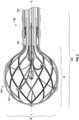
- a system 100 can include a catheter 104, an insertion sleeve 106, and a sheath 108.
- the catheter 104 can include a handle 120, a catheter shaft 122, and an expandable tip 124.
- the handle 120 can be disposed along a proximal portion 136 of the catheter shaft 122, and the expandable tip 124 can be disposed along a distal portion 138 of the catheter shaft 122.
- the expandable tip 124 can be resiliently flexible between an expanded stated and a compressed state and, in the expanded state, a maximum radial dimension of the expandable tip 124 can exceed a maximum radial dimension of a distal portion of the catheter shaft 122 and a maximum radial dimension of the sheath 108.
- the expanded state of the expandable tip 124 includes a state of the expandable tip 124 in the absence of an externally applied force.
- the expandable tip 124 in the expanded state can be used for one or more of diagnosis and treatment at a site within the patient's body.
- the expandable tip 124 in the expanded state can be used for ablating tissue (e.g., through the delivery of radiofrequency (RF) energy) in a cardiac chamber of the patient.
- RF radiofrequency
- the expandable tip 124 can be delivered to a site within the patient's body by moving the expandable tip 124 through the insertion sleeve 106 to compress the expandable tip 124 from the expanded state to the compressed state and moving the expandable tip 124 in the compressed state through the sheath 108 and into vasculature of the patient.
- movement of the expandable tip 124 of the catheter 104 relative to the insertion sleeve 106 can result in compressing the expandable tip 124 from the expanded state to the compressed state with a reduced likelihood of unintended radial expansion (e.g., bulging).
- such reduced likelihood of unintended radial expansion can make insertion of the expandable tip 124 easier for the physician and, further or instead, can reduce the likelihood of damage to the expandable tip 124 during insertion.
- application of force at an angle to the expandable tip 124 can be useful for reducing an overall longitudinal dimension of the insertion sleeve 106, which can be useful for reducing the impact of the insertion sleeve 106 on a usable length of the catheter 104 in instances in which the insertion sleeve 106 remains disposed about the catheter shaft 122 through a medical procedure.
- the expandable tip 124 can have an axial dimension "A” and a radial dimension “R.”
- the axial dimension "A” can be along a direction substantially parallel to a longitudinal axis "L-L” (e.g., a center axis) defined by the catheter shaft 122, and the radial dimension "R” can be perpendicular to the longitudinal axis "L-L” defined by the catheter shaft 122.
- an axial force to the expandable tip 124 in the distal direction and/or application of a radial force to the expandable tip 124 can facilitate compressing the expandable tip 124 while application of an axial force in the proximal direction can result in the expandable tip 124 resisting compression (e.g., through unintended expansion).
- the insertion sleeve 106 can engage the expandable tip 124 to apply a force at an angle, which as compared to force applied by an insertion sleeve having a constant diameter, applies less force on the expandable tip 124 in the proximal direction.
- a force applied at an angle to the expandable tip 124 shall be understood to be a net force having a radial component greater than or equal to an axial component exerted on the expandable tip 124. More specifically, a force applied at an angle to the expandable tip 124 shall be understood to be a net force normal to a tangent of a surface of the expandable tip 124 and oriented at an angle greater than or equal to about 45 degrees with respect to an axial direction parallel to the axial dimension "A.”
- the expandable tip 124 can be resiliently flexible between the expanded state and the compressed state such that one or more of the radial dimension "R" and the axial dimension "A" of the expandable tip 124 changes between the expanded state and the compressed state upon application of the force to the expandable tip 124 at an angle.
- the force applied to the expandable tip 124 at an angle can reduce the radial dimension "R" of the expandable tip 124 such that the expandable tip 124 is movable through the insertion sleeve 106 and through the sheath 108 for insertion into the patient's body.
- the expandable tip 124 can include a coupling portion 140 and a deformable portion 142.
- the coupling portion 140 can be fixed (e.g., through direct or indirect coupling) relative to the catheter shaft 122.
- the deformable portion 142 can extend in a direction distal to the one or more of the coupling portion 140 and the catheter shaft 122.
- the resilient flexing of the expandable tip 124 between the expanded state and the compressed state can include a change in shape of deformable portion 142 of the expandable tip 124.
- the expandable tip 124 can include one or more electrodes useful for diagnosis, treatment, or both at a target site in the patient's body.
- expandability of the expandable tip 124 beyond dimensions of the catheter shaft 122 can facilitate placement of the one or more electrodes beyond dimensions of the catheter shaft 122 at the site of a medical procedure.
- Such placement of one or more electrodes can be useful, for example, for creating large lesions during an ablation treatment.
- the expandable tip 124 can be a continuous structure that acts as one electrode in a monopolar electrode configuration (e.g., in a configuration with one or more return electrode pads positioned external to the patient's body).
- the insertion sleeve 106 can facilitate delivery of a relatively large (e.g., as compared to a maximum radial dimension of the catheter shaft 122) ablation electrode to a treatment site for the formation of large lesions.
- a material for forming the expandable tip 124 can include nitinol (nickel-titanium), which is repeatably and reliably flexible between the expanded state and the compressed state.
- ablation energy can be delivered through the nitinol forming the deformable portion 128 for delivery to tissue to create lesions.
- the deformable portion 128 can include an arrangement of joints and struts that are flexible relative to one another as the expandable tip 124 moves between the expanded state and the compressed state. Blood and/or saline can pass through the openings defined by the joints and struts to cool the expandable tip 124 during a medical procedure.
- the expandable tip 124 can have greater than about 50 percent open area and less than about 95 percent open area (e.g., about 80 percent open area).
- At least the deformable portion 128 of the expandable tip 124 can be self-expandable such that the deformable portion 128 returns to the expanded state upon removing or decreasing a compressive force exerted on the deformable portion 128.
- the deformable portion 128 can be self-expandable such that the deformable portion 128 moves from the compressed state to the expanded state upon exiting the sheath 108 positioned in the body.
- the expandable tip 124 in the expanded state can be based on the size of an anatomic structure in which the expandable tip 124 will be used in the expanded state within the patient.
- the expandable tip 124 can have an outer diameter of greater than about 4 mm and less than about 16 mm (e.g., about 8 mm). It should be appreciated that the type of material and thickness of the material forming the expandable tip 124 can be a function of the flexibility required to flex the expandable tip 124 between the expanded state and the compressed state.
- the expandable tip 124 can be formed of one or more metals (e.g., nitinol) having a thickness of greater than about 0.07 mm and less than about 0.25 mm (e.g., about 0.17 mm).
- metals e.g., nitinol
- the catheter shaft 122 can be formed of any of various different biocompatible materials that provide the catheter shaft 122 with sufficient sturdiness for moving the expandable tip 124 relative to the insertion sleeve 106 and the sheath 108, as described in greater detail below, but also sufficient flexibility to allow the catheter shaft 122 to be navigated through blood vessels of a patient.
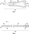
- the insertion sleeve 106 can include a tapered portion 144 and an elongate tube 146 coupled (e.g., directly or indirectly) to one another to define at least a portion of a sleeve lumen 148 extending from a proximal opening 150 to a distal opening 152 defined by the insertion sleeve 106.
- At least a portion of the insertion sleeve 106 can be formed of any one or more of various different materials that are chemically resistant, semi-rigid, and readily suitable to a variety of known manufacturing techniques.
- at least a portion of the insertion sleeve 106 can be formed of one or more of high density polyethylene (HDPE), polytetrafluorethylene (PTFE), and the like.
- HDPE high density polyethylene
- PTFE polytetrafluorethylene
- the proximal opening 150 can have a first open area to receive at least a portion of the expandable tip 124 in the expanded state, and the distal opening 152 can have a second open area less than the first open area.
- the expandable tip 124 can be pushed distally into the insertion sleeve 106 through the proximal opening 150 and, through further distal movement through the insertion sleeve 106, the expandable tip 124 can be pushed out of the insertion sleeve 106 through the distal opening 152.
- further distal movement of the expandable tip 124 in the compressed state beyond the distal opening 152 can deliver the expandable tip 124 into the sheath 108 for introduction, ultimately, into the vasculature of the patient.
- the tapered portion 144 of the insertion sleeve 106 includes a tapered surface 154 defining at least a portion of the sleeve lumen 148.
- the tapered surface 154 can decrease the cross-sectional area of the sleeve lumen 148 in a direction from the proximal opening 150 toward the distal opening 152.
- the expandable tip 124 can slide along the tapered surface 154 such that the tapered surface 154 applies force to the expandable tip 124 at an angle to compress the expandable tip 124 from the expanded state to the compressed state.
- the application of force to the expandable tip 124 at an angle can advantageously reduce the likelihood of unintended deformation of the expandable tip 124 as the expandable tip 124 is delivered into the body of the patient.
- Unintended deformation can be caused by simultaneously applying an inward radial force, which promotes compression of the expandable tip 124, and a proximal axial force, which resists compression of the expandable tip 124.
- the force applied to the expandable tip 124 along the tapered surface 154 can result in a distribution of force in which a radial component of the applied force exceeds a first compressive force required to deform the expandable tip 124 in the radial dimension "R" of the expandable tip 124 while an axial component of the applied force is less than a second compressive force required to deform the expandable tip 124 in the axial dimension "A" of the expandable tip 124. Accordingly, in such instances, the result of the force applied to the expandable tip 124 can be a reduction in the size of the expandable tip 124 in the radial dimension "R" such that the expandable tip 124 can be introduced into the sheath 108.
- the tapered surface 154 can, for example, define a monotonically decreasing area along at least a portion of the tapered portion 144 of the insertion sleeve 106. Additionally, or alternatively, the tapered surface 154 can be substantially symmetric (e.g., substantially frusto-conical) about a plane extending through the proximal opening 150 and the distal opening 152. Such symmetry can be useful for substantially symmetric application of force about a circumference of the expandable tip 124. In general, substantially uniform application of force around the circumference of the expandable tip 124 can be useful for reducing the likelihood of unintended deformation of the expandable tip 124 as the expandable tip 124 is slid along the tapered surface 154.
- the size of an included angle ⁇ between the tapered surface 154 and a center axis "C-C" defined by the sleeve lumen 148 can be bounded by considerations related to reducing the likelihood of unintended deformation and considerations related to an overall axial length of the insertion sleeve 106.
- the included angle ⁇ can be less than a first threshold at which the angled force applied to the expandable tip 124 results in unintended deformation of a portion of the expandable tip 124.
- the included angle ⁇ can be greater than a second threshold, different from the first threshold, limited by considerations related to usable length of the catheter 104.
- the included angle ⁇ can be made shallow to avoid unintended deformation of the expandable tip 124, such a shallow angle can result in an increase in length of the sleeve 108, which may be undesirable in implementations in which the insertion sleeve 106 remains disposed about the catheter shaft 122 during the medical procedure.
- an included angle ⁇ between the tapered surface 154 and the center axis "C-C" defined by the sleeve lumen 148 can be greater than about 4 degrees and less than about 45 degrees. It should be appreciated that this range of angles can be useful for controlling deformation of expandable tip 124 in instances in which, for example, the expandable tip 124 is substantially spherical.
- a substantially spherical shape should be understood to include a shape having at least a hemisphere (e.g., at least a distal hemisphere) lying within a range of the larger of about ⁇ 1 mm or about ⁇ 25% of a nominal radius from a center point.
- At least a portion of the expandable tip 124 can be proximally and distally movable into, through, and beyond the insertion sleeve 106.
- the expandable tip 124 can be moved distally into, through, and beyond the insertion sleeve 106 such that the expandable tip 124 extends beyond the distal opening 152, and the expandable tip 124 can be retracted proximally back into, through, and beyond the distal opening 152 and withdrawn from the insertion sleeve 106.
- an insertion sleeve having a constant diameter similar to that of the sheath 108 can exert forces on the expandable tip 124 that limit or prevent movement of the expandable tip 124 in a distal direction into such a cylindrical sleeve. Accordingly, it should be appreciated that, as compared to a cylindrical sleeve, the ability to move the expandable tip 124 proximally and distally into, through, and beyond the insertion sleeve 106 can, for example, reduce the need to pre-mount the insertion sleeve 106 about the catheter shaft 122.
- the insertion sleeve 106 can be moved in a proximal direction over the expandable tip 124 (e.g., just prior to use) to mount the insertion sleeve 106 for use as part of an insertion procedure. Additionally, or alternatively, the ability to move the expandable tip 124 proximally and distally into, through, and beyond the insertion sleeve 106 can useful for starting the insertion process over, if necessary.
- the elongate tube 146 can extend from the tapered portion 144 in a distal direction.
- the elongate tube 146 can have, for example, a smaller maximum outer dimension than an inner dimension of the sheath 108 such that the elongate tube 146 can be inserted into the sheath 108, as described in greater detail below.
- the elongate tube 146 can be substantially rigid to facilitate insertion of the insertion sleeve 106 into the sheath 108 (e.g., by pushing the elongate tube 146 into engagement with the sheath 108).
- the outer surface of the elongate tube 146 can be tapered in the distal direction to facilitate moving the elongate tube 146 through a valve 170 ( FIG. 4 ) of the sheath 108 with little to no unintended backflow of pressurized fluid from the sheath 108 as the insertion sleeve 106 is mated with the sheath 108.
- the sheath 108 can include a hub 158 and an elongate shaft 160, the elongate shaft 160 having a proximal portion 162 and a distal portion 164.
- the hub 158 can be coupled (e.g., directly or indirectly coupled) to the proximal portion 162 of the elongate shaft 160.
- the sheath 108 can include one or more of an introducer sheath, a steerable sheath, and a fixed curve sheath.
- the elongate shaft 160 can define a sheath lumen 166 extending from the proximal portion 162 to the distal portion 164 of the elongate shaft 160.
- the distal portion of 164 of the elongate shaft 160 can, additionally or alternatively, define an access orifice 168 in fluid communication with the sheath lumen 166.
- the elongate shaft 160 can, for example, have an 8 Fr (e.g., about 2.7 mm) gauge.
- the 8 Fr gauge is a standard size and, therefore, familiar to medical personnel. Additionally, or alternatively, an 8 Fr gauge can advantageously provide vascular access through a small incision that, as compared to larger incisions required for larger gauges, can heal faster and can be less prone to infection.
- the hub 158 can include a valve 170 in fluid communication with the sheath lumen 166.
- the valve 170 can be, for example, a hemostatic valve. Continuing with this example, the valve 170 can restrict the unintended flow of blood from the patient's body in a proximal direction through the hub 158 as the elongate shaft 160 of the sheath 108 is introduced into vasculature of the patient.
- the elongate tube 146 ( FIG. 3 ) of the insertion sleeve 106 ( FIG. 3 ) can extend beyond the valve 170 while the insertion sleeve 106 ( FIG. 3 ) is mated with the sheath 108. It should be appreciated that extending the elongate tube 146 ( FIG. 3 ) beyond the valve 170 can facilitate moving the expandable tip 124 distally past the valve 170 for insertion into the body.
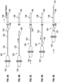
- FIGS. 5A -F schematically illustrate an exemplary method of the disclosure that can be carried out using the system 100 ( FIGS. 1-4 ) to introduce the expandable tip 124 into the patient through the insertion sleeve 106 and the sheath 108.
- the exemplary method of introducing the expandable tip 124 into the patient can include positioning a distal portion 164 of the sheath 108 in a blood vessel of the patient, moving the insertion sleeve 106 over the expandable tip 124 supported by the catheter shaft 122, mating the insertion sleeve 106 with the sheath 108, and advancing the expandable tip 124 distally through the sheath 108 and into the vasculature of the patient.
- a distal portion 164 of the sheath 108 can be positioned within a blood vessel of the patient.
- blood vessels that can be accessed as part of the exemplary method include, but are not limited to, the femoral vein or artery.
- the insertion sleeve 106 can be moved (e.g., in a direction coaxial with the longitudinal axis "L-L" of the catheter shaft 122) over the expandable tip 124 supported by the catheter shaft 122.
- the expandable tip 124 can be pushed in a distal direction into the insertion sleeve 106.
- the tapered surface 154 of the insertion sleeve 106 can compress at least a portion of the expandable tip 124 from the expanded state to the compressed state.
- the expandable tip 124 can engage the tapered surface 154 of the insertion sleeve 106 such that the insertion sleeve 106 exerts a force on the expandable tip 124 at an angle to reduce the likelihood of unintended deformation of the expandable tip 124.
- the insertion sleeve 106 can be mated with (e.g., inserted into) the sheath 108.
- Mating the insertion sleeve 106 with the sheath 108 can include, for example, positioning a portion (e.g., the elongate tube 146) of the insertion sleeve 106 within the sheath lumen 166 of the sheath 108.
- mating the insertion sleeve 106 with the sheath 108 can include positioning a portion of the insertion sleeve 106 in the sheath lumen 166 at a position distal to the valve 170 of the sheath 108.
- the portion of the insertion sleeve 106 extending to the position distal to the valve 170 can exert a force sufficient to open the valve 170 during the insertion procedure.
- the sheath 108 can block further distal movement of the insertion sleeve 106 relative to the sheath 108 to facilitate properly positioning of the insertion sleeve 106 relative to the sheath 108 during an insertion procedure.
- the insertion sleeve 106 can be mated with the sheath 108. It should be understood, however, that the order of collapsing the expandable tip 124 and mating the insertion sleeve 106 with the sheath 108 can be reversed. Thus, for example, in such implementations, the user can insert the insertion sleeve 106 into the sheath 108 and then, with the insertion sleeve 106 mated with the sheath 108, advance the expandable tip 124 distally into the insertion sleeve 106.
- the insertion sleeve 106 can be retracted (e.g., moved in a proximal direction relative to the sheath 108, and the expandable tip 124 can be advanced distally through the sheath 108 and into the vasculature of the patient.
- the expandable tip 124 can be collapsible from the expanded state to the compressed state through both distal movement and proximal movement of the expandable tip 124 through the insertion sleeve 106. In such implementations, therefore, the expandable tip 124 can be retracted proximally from the sheath lumen 166 and into the insertion sleeve 106 to collapse the expandable tip from the expanded state to the compressed state. It should be understood that retraction of the expandable tip 124 into the insertion sleeve 106 from the sheath lumen 166 can be useful, for example, for starting the insertion process over.
- the expandable tip 124 can be extended distally beyond the access orifice 168 of the sheath 108 such that the expandable tip 124 can expand (e.g., self-expand) from the compressed state to the expanded state.
- the expandable tip 124 can be moved to a target site and a medical procedure can be performed.
- the medical procedure can be any one or more of various different diagnostic and treatment procedures.
- the medical procedure can be any of various different medical procedures associated with at least one of diagnosis and treatment of a cardiac condition, and, accordingly, the expandable tip 124 can be positioned in a cardiac chamber of the patient.
- the insertion sleeve 106 can be left surrounding the proximal portion 136 of the catheter shaft 122 throughout the remainder of the treatment. In some implementations, the insertion sleeve 106 can be removed from the catheter shaft 122 while the at least one portion of the expandable tip 124 is in the vasculature of the patient. For example, the insertion sleeve 106 can include a break-away portion that can be removed to remove the insertion sleeve 106 from the catheter shaft 122.
- the expandable tip 124 can also, or instead, be mechanically actuated to expand from the compressed state to the expanded state.
- Such mechanical actuation can include, for example, a wire coupled to a distal portion of the expandable tip 124.
- the expandable tip 124 can be expanded from the compressed state to the expanded state by pulling the wire in a proximal direction.
- the insertion sleeves have been described as being used to deliver a catheter including an expandable tip, it should be appreciated that the insertion sleeves of the present disclosure can additionally, or alternatively, be used to deliver other types of catheters into a sheath.
- the insertion sleeves of the present disclosure can be used to deliver a catheter formed of a plurality of splines (e.g., in the shape of a basket, in an open arrangement, or a combination thereof), such as catheters commonly used for mapping.
- performing the step of X includes any suitable method for causing another party such as a remote user, a remote processing resource (e.g., a server or cloud computer) or a machine to perform the step of X.
- performing steps X, Y and Z may include any method of directing or controlling any combination of such other individuals or resources to perform steps X, Y and Z to obtain the benefit of such steps.
Landscapes
- Health & Medical Sciences (AREA)
- Life Sciences & Earth Sciences (AREA)
- Engineering & Computer Science (AREA)
- Surgery (AREA)
- Public Health (AREA)
- Animal Behavior & Ethology (AREA)
- Veterinary Medicine (AREA)
- General Health & Medical Sciences (AREA)
- Biomedical Technology (AREA)
- Heart & Thoracic Surgery (AREA)
- Molecular Biology (AREA)
- Medical Informatics (AREA)
- Physics & Mathematics (AREA)
- Nuclear Medicine, Radiotherapy & Molecular Imaging (AREA)
- Biophysics (AREA)
- Plasma & Fusion (AREA)
- Otolaryngology (AREA)
- Hematology (AREA)
- Anesthesiology (AREA)
- Pulmonology (AREA)
- Pathology (AREA)
- Cardiology (AREA)
- Optics & Photonics (AREA)
- Radiology & Medical Imaging (AREA)
- Neurology (AREA)
- Neurosurgery (AREA)
- Surgical Instruments (AREA)
- Media Introduction/Drainage Providing Device (AREA)
- Endoscopes (AREA)
Description
- Catheters are used for a variety of procedures related to diagnosis and treatment of medical conditions in patients. Physical limitations exist, however, with respect to the size of a catheter that can be introduced into a body of a patient. Such limitations can constrain the size of a distal portion of the catheter available for diagnosis or treatment at a location within the body of the patient.
US2010/204560 A1 describes a system comprising a catheter with an expandable tip, a sheath, an insertion sleeve with a tapered surface positioned over the sheath. Engagement with the tapered surface compresses the expandable tip from the expanded state to the compressed state. - Devices and systems of the disclosure can overcome physical constraints associated with catheter introduction to facilitate the use of a catheter with a large distal portion as part of a medical procedure benefitting from such a large distal portion, such as, for example, cardiac ablation. The methods of treatment discussed throughout the disclosure do not form part of the claimed invention and are provided for illustration purposes only. More specifically, devices, systems, and methods of the present disclosure can compress an expandable tip of a catheter from an expanded state to a compressed state along a tapered surface of an insertion sleeve for advancement of the expandable tip into vasculature of a patient. The tapered surface of the insertion sleeve can, for example, apply compressive forces at an angle against the advancing expandable tip. As compared to other approaches to the application of compressive force to an expandable tip, compressing the expandable tip using an angled force can reduce the likelihood of unintended deformation of, or damage to the expandable tip.
- In one aspect of the disclosure, a method of inserting a catheter into vasculature of a patient includes positioning a distal portion of a sheath in a blood vessel of the patient, moving an insertion sleeve proximally over an expandable tip supported by a catheter shaft, the proximal movement of the insertion sleeve compressing at least one portion of the expandable tip from an expanded state to a compressed state along a tapered surface of the insertion sleeve, mating the insertion sleeve with the sheath, and advancing the expandable tip distally beyond the sheath and into the vasculature of the patient.
- In certain implementations, the insertion sleeve can be mated with the sheath with the expandable tip disposed in the insertion sleeve in the compressed state.
- In some implementations, at least one portion of the expandable tip in the expanded state can have a maximum radial dimension greater than a maximum radial dimension of the sheath.
- In certain implementations, the at least one portion of the expandable tip can be resiliently flexible between the expanded state and the compressed state in response to addition and removal of external force applied to the at least one portion of the expandable tip.
- In some implementations, the insertion sleeve can define a proximal opening and a distal opening, and the proximal opening is larger than the distal opening. For example, the at least one portion of the expandable tip can be collapsible from the expanded state to the compressed state through both distal movement of the expandable tip through the proximal opening of the insertion sleeve and through proximal movement of the expandable tip through the distal opening of the insertion sleeve. Additionally, or alternatively, the method of the disclosure can further include retracting the expandable tip proximally through the distal opening and collapsing the expandable tip from the expanded state to the compressed state.
- In certain implementations, mating the insertion sleeve with the sheath can include positioning a portion of the insertion sleeve within a sheath lumen defined by the sheath. For example, mating the insertion sleeve with the sheath can include positioning a portion of the insertion sleeve in the sheath lumen at a position distal to a valve of the sheath. Additionally, or alternatively, the portion of the insertion sleeve positioned in the sheath lumen can be an elongate tube (e.g., tapered in a distal direction). Further, or instead, with the portion of the insertion sleeve in the sheath lumen at the position distal to the valve of the sheath, the sheath can block further distal movement of the insertion sleeve.
- In some implementations, advancing the expandable tip distally beyond the sheath can include expanding the at least one portion of the expandable tip from the compressed state to the expanded state. For example, the at least one portion of the expandable tip is self-expandable from the compressed state to the expanded state.
- In certain implementations, the sheath can have an 8 Fr diameter.
- In some implementations, the tapered surface of the insertion sleeve can be substantially frusto-conical. Additionally, or alternatively, an included angle defined between the tapered surface and a center axis defined by the insertion sleeve can be greater than about 4 degrees and less than about 45 degrees.
- In certain implementations, the method can further include removing the insertion sleeve from the catheter shaft while the at least one portion of the expandable tip is in the vasculature of the patient. For example, the insertion sleeve can include a break-away portion and removing the insertion sleeve from the catheter shaft can include removing the break-away portion from the insertion sleeve.
- In certain implementations, the sheath can be one or more of an introducer sheath, a steerable sheath, and a fixed curve sheath.
- In some implementations, the expandable tip can include one or more electrodes. For example, the expandable tip can be an ablation electrode.
- In another aspect, a system can include a catheter including a shaft and an expandable tip disposed along a distal portion of the shaft, at least one portion of the expandable tip resiliently flexible between an expanded state and a compressed state, a sheath defining a sheath lumen, the at least one portion of the expandable tip, in the compressed state, movable through the sheath lumen, and an insertion sleeve including a tapered surface defining at least a portion of a sleeve lumen, the at least one portion of the expandable tip movable into engagement with the tapered surface, the engagement of the tapered surface compressing the at least one portion of the expandable tip from the expanded state to the compressed state as the at least one portion of the expandable tip is moved through the sleeve lumen in a direction toward the sheath lumen.
- In certain implementations, the tapered surface of the insertion sleeve can be substantially frusto-conical. For example, an included angle defined between the tapered surface and a center axis defined by the sleeve lumen of the insertion sleeve can be greater than about 4 degrees and less than about 45 degrees. Additionally, or alternatively, the insertion sleeve can define a proximal opening and a distal opening, the proximal opening having a first open area to receive the at least one portion of the expandable tip in the expanded state and the distal opening having a second open area less than the first open area.
- In some implementations, the at least one portion of the expandable tip can be proximally and distally movable through the insertion sleeve.
- In certain implementations, the sheath can include a valve and the insertion sleeve can include an elongate tube, the insertion sleeve engageable with the sheath, and the elongate tube sized to extend beyond the valve with the insertion sleeve engaged with the sheath. The elongate tube can be, for example, tapered in a distal direction.
- In some implementations, the sheath can include one or more of an introducer sheath, a steerable sheath, and a fixed curve sheath.
- In certain implementations, the expandable tip can include one or more electrodes. For example, the expandable tip can be an ablation electrode.
- Other aspects, features, and advantages will be apparent from the description and drawings, and from the claims.
-
-
FIG. 1 is a perspective view of a system including a catheter, a sheath, and an insertion sleeve. -
FIG. 2 is a cross-sectional perspective view of an expandable tip of the catheter along cross-section A-A ofFIG. 1 -
FIG. 3 is a cross-sectional view of the insertion sleeve ofFIG. 1 along cross-section A-A ofFIG. 1 . -
FIG. 4 is a cross-sectional view of the sheath ofFIG. 1 along cross-section A-A ofFIG. 1 . -
FIGS. 5A-5E are schematic representations of steps of an exemplary method of the disclosure using the system ofFIG. 1 to insert the expandable tip of the catheter ofFIG. 2 into a patient. - Like reference symbols in the various drawings indicate like elements.
- Referring now to
FIG. 1 , asystem 100 can include acatheter 104, aninsertion sleeve 106, and asheath 108. Thecatheter 104 can include ahandle 120, acatheter shaft 122, and anexpandable tip 124. Thehandle 120 can be disposed along aproximal portion 136 of thecatheter shaft 122, and theexpandable tip 124 can be disposed along adistal portion 138 of thecatheter shaft 122. In general, theexpandable tip 124 can be resiliently flexible between an expanded stated and a compressed state and, in the expanded state, a maximum radial dimension of theexpandable tip 124 can exceed a maximum radial dimension of a distal portion of thecatheter shaft 122 and a maximum radial dimension of thesheath 108. As used herein, the expanded state of theexpandable tip 124 includes a state of theexpandable tip 124 in the absence of an externally applied force. In exemplary uses, theexpandable tip 124 in the expanded state can be used for one or more of diagnosis and treatment at a site within the patient's body. As a specific example, theexpandable tip 124 in the expanded state can be used for ablating tissue (e.g., through the delivery of radiofrequency (RF) energy) in a cardiac chamber of the patient. - In use, the
expandable tip 124 can be delivered to a site within the patient's body by moving theexpandable tip 124 through theinsertion sleeve 106 to compress theexpandable tip 124 from the expanded state to the compressed state and moving theexpandable tip 124 in the compressed state through thesheath 108 and into vasculature of the patient. For example, as described in greater detail below, movement of theexpandable tip 124 of thecatheter 104 relative to theinsertion sleeve 106 can result in compressing theexpandable tip 124 from the expanded state to the compressed state with a reduced likelihood of unintended radial expansion (e.g., bulging). In general, such reduced likelihood of unintended radial expansion can make insertion of theexpandable tip 124 easier for the physician and, further or instead, can reduce the likelihood of damage to theexpandable tip 124 during insertion. Additionally, or alternatively, as further described in greater detail below, application of force at an angle to theexpandable tip 124 can be useful for reducing an overall longitudinal dimension of theinsertion sleeve 106, which can be useful for reducing the impact of theinsertion sleeve 106 on a usable length of thecatheter 104 in instances in which theinsertion sleeve 106 remains disposed about thecatheter shaft 122 through a medical procedure. - Referring now to
FIGS. 1 and2 , theexpandable tip 124 can have an axial dimension "A" and a radial dimension "R." The axial dimension "A" can be along a direction substantially parallel to a longitudinal axis "L-L" (e.g., a center axis) defined by thecatheter shaft 122, and the radial dimension "R" can be perpendicular to the longitudinal axis "L-L" defined by thecatheter shaft 122. In general, application of an axial force to theexpandable tip 124 in the distal direction and/or application of a radial force to theexpandable tip 124 can facilitate compressing theexpandable tip 124 while application of an axial force in the proximal direction can result in theexpandable tip 124 resisting compression (e.g., through unintended expansion). Accordingly, theinsertion sleeve 106 can engage theexpandable tip 124 to apply a force at an angle, which as compared to force applied by an insertion sleeve having a constant diameter, applies less force on theexpandable tip 124 in the proximal direction. As used herein, a force applied at an angle to theexpandable tip 124 shall be understood to be a net force having a radial component greater than or equal to an axial component exerted on theexpandable tip 124. More specifically, a force applied at an angle to theexpandable tip 124 shall be understood to be a net force normal to a tangent of a surface of theexpandable tip 124 and oriented at an angle greater than or equal to about 45 degrees with respect to an axial direction parallel to the axial dimension "A." In general, theexpandable tip 124 can be resiliently flexible between the expanded state and the compressed state such that one or more of the radial dimension "R" and the axial dimension "A" of theexpandable tip 124 changes between the expanded state and the compressed state upon application of the force to theexpandable tip 124 at an angle. For example, the force applied to theexpandable tip 124 at an angle can reduce the radial dimension "R" of theexpandable tip 124 such that theexpandable tip 124 is movable through theinsertion sleeve 106 and through thesheath 108 for insertion into the patient's body. - The
expandable tip 124 can include acoupling portion 140 and adeformable portion 142. Thecoupling portion 140 can be fixed (e.g., through direct or indirect coupling) relative to thecatheter shaft 122. Thedeformable portion 142 can extend in a direction distal to the one or more of thecoupling portion 140 and thecatheter shaft 122. In response to changes in force applied to theexpandable tip 124, the resilient flexing of theexpandable tip 124 between the expanded state and the compressed state can include a change in shape ofdeformable portion 142 of theexpandable tip 124. - The
expandable tip 124 can include one or more electrodes useful for diagnosis, treatment, or both at a target site in the patient's body. In general, expandability of theexpandable tip 124 beyond dimensions of thecatheter shaft 122 can facilitate placement of the one or more electrodes beyond dimensions of thecatheter shaft 122 at the site of a medical procedure. Such placement of one or more electrodes can be useful, for example, for creating large lesions during an ablation treatment. - In certain implementations, the
expandable tip 124 can be a continuous structure that acts as one electrode in a monopolar electrode configuration (e.g., in a configuration with one or more return electrode pads positioned external to the patient's body). In such implementations, theinsertion sleeve 106 can facilitate delivery of a relatively large (e.g., as compared to a maximum radial dimension of the catheter shaft 122) ablation electrode to a treatment site for the formation of large lesions. As an example, a material for forming theexpandable tip 124 can include nitinol (nickel-titanium), which is repeatably and reliably flexible between the expanded state and the compressed state. Continuing with this example, it should be appreciated that ablation energy can be delivered through the nitinol forming the deformable portion 128 for delivery to tissue to create lesions. - Additionally, or alternatively, the deformable portion 128 can include an arrangement of joints and struts that are flexible relative to one another as the
expandable tip 124 moves between the expanded state and the compressed state. Blood and/or saline can pass through the openings defined by the joints and struts to cool theexpandable tip 124 during a medical procedure. For example, theexpandable tip 124 can have greater than about 50 percent open area and less than about 95 percent open area (e.g., about 80 percent open area). - In certain implementations, at least the deformable portion 128 of the
expandable tip 124 can be self-expandable such that the deformable portion 128 returns to the expanded state upon removing or decreasing a compressive force exerted on the deformable portion 128. As a more specific example, the deformable portion 128 can be self-expandable such that the deformable portion 128 moves from the compressed state to the expanded state upon exiting thesheath 108 positioned in the body. - The
expandable tip 124 in the expanded state can be based on the size of an anatomic structure in which theexpandable tip 124 will be used in the expanded state within the patient. For example, in implementations in which theexpandable tip 124 is used for diagnosis and/or treatment of cardiac conditions, theexpandable tip 124 can have an outer diameter of greater than about 4 mm and less than about 16 mm (e.g., about 8 mm). It should be appreciated that the type of material and thickness of the material forming theexpandable tip 124 can be a function of the flexibility required to flex theexpandable tip 124 between the expanded state and the compressed state. Thus, for example, in implementations in which theexpandable tip 124 is used for one or more of diagnosis and treatment of cardiac conditions and it is desirable to deliver theexpandable tip 124 into vasculature of the patient through thesheath 108 having an 8 Fr gauge, theexpandable tip 124 can be formed of one or more metals (e.g., nitinol) having a thickness of greater than about 0.07 mm and less than about 0.25 mm (e.g., about 0.17 mm). - The
catheter shaft 122 can be formed of any of various different biocompatible materials that provide thecatheter shaft 122 with sufficient sturdiness for moving theexpandable tip 124 relative to theinsertion sleeve 106 and thesheath 108, as described in greater detail below, but also sufficient flexibility to allow thecatheter shaft 122 to be navigated through blood vessels of a patient. - Referring now to
FIGS. 1 and3 , theinsertion sleeve 106 can include a taperedportion 144 and anelongate tube 146 coupled (e.g., directly or indirectly) to one another to define at least a portion of asleeve lumen 148 extending from aproximal opening 150 to adistal opening 152 defined by theinsertion sleeve 106. At least a portion of theinsertion sleeve 106 can be formed of any one or more of various different materials that are chemically resistant, semi-rigid, and readily suitable to a variety of known manufacturing techniques. By way of example, and not limitation, at least a portion of theinsertion sleeve 106 can be formed of one or more of high density polyethylene (HDPE), polytetrafluorethylene (PTFE), and the like. - In general, the
proximal opening 150 can have a first open area to receive at least a portion of theexpandable tip 124 in the expanded state, and thedistal opening 152 can have a second open area less than the first open area. In use, theexpandable tip 124 can be pushed distally into theinsertion sleeve 106 through theproximal opening 150 and, through further distal movement through theinsertion sleeve 106, theexpandable tip 124 can be pushed out of theinsertion sleeve 106 through thedistal opening 152. As described in greater detail below, further distal movement of theexpandable tip 124 in the compressed state beyond thedistal opening 152 can deliver theexpandable tip 124 into thesheath 108 for introduction, ultimately, into the vasculature of the patient. - The tapered
portion 144 of theinsertion sleeve 106 includes atapered surface 154 defining at least a portion of thesleeve lumen 148. In general, thetapered surface 154 can decrease the cross-sectional area of thesleeve lumen 148 in a direction from theproximal opening 150 toward thedistal opening 152. Thus, as theexpandable tip 124 is moved in the direction from theproximal opening 150 toward thedistal opening 152, at least a portion of theexpandable tip 124 can slide along the taperedsurface 154 such that thetapered surface 154 applies force to theexpandable tip 124 at an angle to compress theexpandable tip 124 from the expanded state to the compressed state. - In general, the application of force to the
expandable tip 124 at an angle can advantageously reduce the likelihood of unintended deformation of theexpandable tip 124 as theexpandable tip 124 is delivered into the body of the patient. Unintended deformation can be caused by simultaneously applying an inward radial force, which promotes compression of theexpandable tip 124, and a proximal axial force, which resists compression of theexpandable tip 124. The force applied to theexpandable tip 124 along the taperedsurface 154 can result in a distribution of force in which a radial component of the applied force exceeds a first compressive force required to deform theexpandable tip 124 in the radial dimension "R" of theexpandable tip 124 while an axial component of the applied force is less than a second compressive force required to deform theexpandable tip 124 in the axial dimension "A" of theexpandable tip 124. Accordingly, in such instances, the result of the force applied to theexpandable tip 124 can be a reduction in the size of theexpandable tip 124 in the radial dimension "R" such that theexpandable tip 124 can be introduced into thesheath 108. - The
tapered surface 154 can, for example, define a monotonically decreasing area along at least a portion of the taperedportion 144 of theinsertion sleeve 106. Additionally, or alternatively, thetapered surface 154 can be substantially symmetric (e.g., substantially frusto-conical) about a plane extending through theproximal opening 150 and thedistal opening 152. Such symmetry can be useful for substantially symmetric application of force about a circumference of theexpandable tip 124. In general, substantially uniform application of force around the circumference of theexpandable tip 124 can be useful for reducing the likelihood of unintended deformation of theexpandable tip 124 as theexpandable tip 124 is slid along the taperedsurface 154. - In general, the size of an included angle θ between the
tapered surface 154 and a center axis "C-C" defined by thesleeve lumen 148 can be bounded by considerations related to reducing the likelihood of unintended deformation and considerations related to an overall axial length of theinsertion sleeve 106. For example, the included angle θ can be less than a first threshold at which the angled force applied to theexpandable tip 124 results in unintended deformation of a portion of theexpandable tip 124. Continuing with this example, the included angle θ can be greater than a second threshold, different from the first threshold, limited by considerations related to usable length of thecatheter 104. That is, while the included angle θ can be made shallow to avoid unintended deformation of theexpandable tip 124, such a shallow angle can result in an increase in length of thesleeve 108, which may be undesirable in implementations in which theinsertion sleeve 106 remains disposed about thecatheter shaft 122 during the medical procedure. - In implementations in which the tapered
surface 150 is substantially frusto-conical, an included angle θ between thetapered surface 154 and the center axis "C-C" defined by thesleeve lumen 148 can be greater than about 4 degrees and less than about 45 degrees. It should be appreciated that this range of angles can be useful for controlling deformation ofexpandable tip 124 in instances in which, for example, theexpandable tip 124 is substantially spherical. As used herein, a substantially spherical shape should be understood to include a shape having at least a hemisphere (e.g., at least a distal hemisphere) lying within a range of the larger of about ± 1 mm or about ± 25% of a nominal radius from a center point. - In some implementations, at least a portion of the
expandable tip 124 can be proximally and distally movable into, through, and beyond theinsertion sleeve 106. For example, theexpandable tip 124 can be moved distally into, through, and beyond theinsertion sleeve 106 such that theexpandable tip 124 extends beyond thedistal opening 152, and theexpandable tip 124 can be retracted proximally back into, through, and beyond thedistal opening 152 and withdrawn from theinsertion sleeve 106. By comparison, however, an insertion sleeve having a constant diameter similar to that of thesheath 108 can exert forces on theexpandable tip 124 that limit or prevent movement of theexpandable tip 124 in a distal direction into such a cylindrical sleeve. Accordingly, it should be appreciated that, as compared to a cylindrical sleeve, the ability to move theexpandable tip 124 proximally and distally into, through, and beyond theinsertion sleeve 106 can, for example, reduce the need to pre-mount theinsertion sleeve 106 about thecatheter shaft 122. For example, because theexpandable tip 124 is proximally and distally movable into, through, and beyond theinsertion sleeve 106, theinsertion sleeve 106 can be moved in a proximal direction over the expandable tip 124 (e.g., just prior to use) to mount theinsertion sleeve 106 for use as part of an insertion procedure. Additionally, or alternatively, the ability to move theexpandable tip 124 proximally and distally into, through, and beyond theinsertion sleeve 106 can useful for starting the insertion process over, if necessary. - In general, the
elongate tube 146 can extend from the taperedportion 144 in a distal direction. Theelongate tube 146 can have, for example, a smaller maximum outer dimension than an inner dimension of thesheath 108 such that theelongate tube 146 can be inserted into thesheath 108, as described in greater detail below. Theelongate tube 146 can be substantially rigid to facilitate insertion of theinsertion sleeve 106 into the sheath 108 (e.g., by pushing theelongate tube 146 into engagement with the sheath 108). Additionally, or alternatively, the outer surface of theelongate tube 146 can be tapered in the distal direction to facilitate moving theelongate tube 146 through a valve 170 (FIG. 4 ) of thesheath 108 with little to no unintended backflow of pressurized fluid from thesheath 108 as theinsertion sleeve 106 is mated with thesheath 108. - Referring now to
FIGS. 1 and4 , thesheath 108 can include ahub 158 and anelongate shaft 160, theelongate shaft 160 having a proximal portion 162 and adistal portion 164. Thehub 158 can be coupled (e.g., directly or indirectly coupled) to the proximal portion 162 of theelongate shaft 160. In general, thesheath 108 can include one or more of an introducer sheath, a steerable sheath, and a fixed curve sheath. - The
elongate shaft 160 can define asheath lumen 166 extending from the proximal portion 162 to thedistal portion 164 of theelongate shaft 160. The distal portion of 164 of theelongate shaft 160 can, additionally or alternatively, define anaccess orifice 168 in fluid communication with thesheath lumen 166. Theelongate shaft 160 can, for example, have an 8 Fr (e.g., about 2.7 mm) gauge. The 8 Fr gauge is a standard size and, therefore, familiar to medical personnel. Additionally, or alternatively, an 8 Fr gauge can advantageously provide vascular access through a small incision that, as compared to larger incisions required for larger gauges, can heal faster and can be less prone to infection. - The
hub 158 can include avalve 170 in fluid communication with thesheath lumen 166. Thevalve 170 can be, for example, a hemostatic valve. Continuing with this example, thevalve 170 can restrict the unintended flow of blood from the patient's body in a proximal direction through thehub 158 as theelongate shaft 160 of thesheath 108 is introduced into vasculature of the patient. In use, the elongate tube 146 (FIG. 3 ) of the insertion sleeve 106 (FIG. 3 ) can extend beyond thevalve 170 while the insertion sleeve 106 (FIG. 3 ) is mated with thesheath 108. It should be appreciated that extending the elongate tube 146 (FIG. 3 ) beyond thevalve 170 can facilitate moving theexpandable tip 124 distally past thevalve 170 for insertion into the body. - Referring now to A, to perform a medical treatment in the body of the patient, the
distal portion 138 of thecatheter shaft 122 and, thus, theexpandable tip 124 can be introduced into the patient and then delivered to a target site.FIGS. 5A -F schematically illustrate an exemplary method of the disclosure that can be carried out using the system 100 (FIGS. 1-4 ) to introduce theexpandable tip 124 into the patient through theinsertion sleeve 106 and thesheath 108. In general, as described in greater detail below, the exemplary method of introducing theexpandable tip 124 into the patient can include positioning adistal portion 164 of thesheath 108 in a blood vessel of the patient, moving theinsertion sleeve 106 over theexpandable tip 124 supported by thecatheter shaft 122, mating theinsertion sleeve 106 with thesheath 108, and advancing theexpandable tip 124 distally through thesheath 108 and into the vasculature of the patient. - Referring now to
FIGS. 1-4 and5A , adistal portion 164 of thesheath 108 can be positioned within a blood vessel of the patient. Examples of blood vessels that can be accessed as part of the exemplary method include, but are not limited to, the femoral vein or artery. - Referring now to
FIGS. 1-4 and5B , theinsertion sleeve 106 can be moved (e.g., in a direction coaxial with the longitudinal axis "L-L" of the catheter shaft 122) over theexpandable tip 124 supported by thecatheter shaft 122. For example, theexpandable tip 124 can be pushed in a distal direction into theinsertion sleeve 106. Through such distal movement of theexpandable tip 124 into theinsertion sleeve 106, thetapered surface 154 of theinsertion sleeve 106 can compress at least a portion of theexpandable tip 124 from the expanded state to the compressed state. For example, as theexpandable tip 124 is pushed distally into theinsertion sleeve 106, theexpandable tip 124 can engage the taperedsurface 154 of theinsertion sleeve 106 such that theinsertion sleeve 106 exerts a force on theexpandable tip 124 at an angle to reduce the likelihood of unintended deformation of theexpandable tip 124. - Referring now to
FIGS. 1-4 and5C , theinsertion sleeve 106 can be mated with (e.g., inserted into) thesheath 108. Mating theinsertion sleeve 106 with thesheath 108 can include, for example, positioning a portion (e.g., the elongate tube 146) of theinsertion sleeve 106 within thesheath lumen 166 of thesheath 108. Additionally, or alternatively, mating theinsertion sleeve 106 with thesheath 108 can include positioning a portion of theinsertion sleeve 106 in thesheath lumen 166 at a position distal to thevalve 170 of thesheath 108. Continuing with this example, the portion of theinsertion sleeve 106 extending to the position distal to thevalve 170 can exert a force sufficient to open thevalve 170 during the insertion procedure. With the portion of theinsertion sleeve 106 in thesheath lumen 166 at a position distal to thevalve 170 of thesheath 108, thesheath 108 can block further distal movement of theinsertion sleeve 106 relative to thesheath 108 to facilitate properly positioning of theinsertion sleeve 106 relative to thesheath 108 during an insertion procedure. - In certain implementations, with the
expandable tip 124 collapsed within theinsertion sleeve 106, theinsertion sleeve 106 can be mated with thesheath 108. It should be understood, however, that the order of collapsing theexpandable tip 124 and mating theinsertion sleeve 106 with thesheath 108 can be reversed. Thus, for example, in such implementations, the user can insert theinsertion sleeve 106 into thesheath 108 and then, with theinsertion sleeve 106 mated with thesheath 108, advance theexpandable tip 124 distally into theinsertion sleeve 106. - Referring now to
FIGS. 1-4 and5D , with theexpandable tip 124 disposed in thesheath 108, theinsertion sleeve 106 can be retracted (e.g., moved in a proximal direction relative to thesheath 108, and theexpandable tip 124 can be advanced distally through thesheath 108 and into the vasculature of the patient. - In certain implementations, the
expandable tip 124 can be collapsible from the expanded state to the compressed state through both distal movement and proximal movement of theexpandable tip 124 through theinsertion sleeve 106. In such implementations, therefore, theexpandable tip 124 can be retracted proximally from thesheath lumen 166 and into theinsertion sleeve 106 to collapse the expandable tip from the expanded state to the compressed state. It should be understood that retraction of theexpandable tip 124 into theinsertion sleeve 106 from thesheath lumen 166 can be useful, for example, for starting the insertion process over. - Referring now to
FIGS. 1-4 and5E , theexpandable tip 124 can be extended distally beyond theaccess orifice 168 of thesheath 108 such that theexpandable tip 124 can expand (e.g., self-expand) from the compressed state to the expanded state. In the expanded state, theexpandable tip 124 can be moved to a target site and a medical procedure can be performed. In general, the medical procedure can be any one or more of various different diagnostic and treatment procedures. Thus, for example, the medical procedure can be any of various different medical procedures associated with at least one of diagnosis and treatment of a cardiac condition, and, accordingly, theexpandable tip 124 can be positioned in a cardiac chamber of the patient. - In certain implementations, the
insertion sleeve 106 can be left surrounding theproximal portion 136 of thecatheter shaft 122 throughout the remainder of the treatment. In some implementations, theinsertion sleeve 106 can be removed from thecatheter shaft 122 while the at least one portion of theexpandable tip 124 is in the vasculature of the patient. For example, theinsertion sleeve 106 can include a break-away portion that can be removed to remove theinsertion sleeve 106 from thecatheter shaft 122. - While certain implementations have been described, other implementations possible.
- As an example, while the
expandable tip 124 has been described as being self-expandable from the compressed state to the expanded state, theexpandable tip 124 can also, or instead, be mechanically actuated to expand from the compressed state to the expanded state. Such mechanical actuation can include, for example, a wire coupled to a distal portion of theexpandable tip 124. In such instances, theexpandable tip 124 can be expanded from the compressed state to the expanded state by pulling the wire in a proximal direction. - As another example, while the insertion sleeves have been described as being used to deliver a catheter including an expandable tip, it should be appreciated that the insertion sleeves of the present disclosure can additionally, or alternatively, be used to deliver other types of catheters into a sheath. As an example, the insertion sleeves of the present disclosure can be used to deliver a catheter formed of a plurality of splines (e.g., in the shape of a basket, in an open arrangement, or a combination thereof), such as catheters commonly used for mapping.
- The method steps of the implementations of the disclosure described herein are intended to include any suitable method of causing such method steps to be performed, consistent with the patentability of the following claims, unless a different meaning is expressly provided or otherwise clear from the context. So, for example performing the step of X includes any suitable method for causing another party such as a remote user, a remote processing resource (e.g., a server or cloud computer) or a machine to perform the step of X. Similarly, performing steps X, Y and Z may include any method of directing or controlling any combination of such other individuals or resources to perform steps X, Y and Z to obtain the benefit of such steps. Thus, method steps of the implementations described herein are intended to include any suitable method of causing one or more other parties or entities to perform the steps, consistent with the patentability of the following claims, unless a different meaning is expressly provided or otherwise clear from the context. Such parties or entities need not be under the direction or control of any other party or entity, and need not be located within a particular jurisdiction.
- It will be appreciated that the systems, and the methods and of the disclosure described above are set forth by way of example and not of limitation. Thus, while particular embodiments have been shown and described, it will be apparent to those skilled in the art that various changes and modifications in form and details may be made therein without departing from the scope of this disclosure and are intended to form a part of the invention as defined by the following claims, which are to be interpreted in the broadest sense allowable by law.
Claims (12)
- A system (100) comprising:a catheter (104) including a shaft (122) and an expandable tip (124) disposed along a distal portion of the shaft (138), at least one portion of the expandable tip resiliently flexible between an expanded state and a compressed state;a sheath (108) defining a sheath lumen (166) andan insertion sleeve (106) including a tapered surface (154) defining at least a portion of a sleeve lumen (148), wherein the insertion sleeve is configured to mate with the sheath such that a distal portion of the insertion sleeve is positioned in a proximal portion of the sheath lumen, andwherein, during operation, the at least one portion of the expandable tip is distally movable through the sleeve lumen of the insertion sleeve in a direction toward the sheath lumen such that engagement with the tapered surface compresses the at least one portion of the expandable tip from the expanded state to the compressed state before the at least one portion of the expandable tip enters the sheath lumen.
- The system of claim 1, wherein the tapered surface of the insertion sleeve is substantially frusto-conical.
- The system of claim 2, wherein an included angle defined between the tapered surface and a center axis defined by the sleeve lumen of the insertion sleeve is greater than about 4 degrees and less than about 45 degrees.
- The system of any one or more of claims 1-3, wherein the insertion sleeve defines a proximal opening and a distal opening, the proximal opening having a first open area to receive the at least one portion of the expandable tip in the expanded state and the distal opening having a second open area less than the first open area.
- The system of any one or more of claims 1-4, wherein the at least one portion of the expandable tip is proximally and distally movable through the insertion sleeve.
- The system of any one or more of claims 1-5, wherein the sheath includes a valve and the insertion sleeve includes an elongate tube, the insertion sleeve is mated with the sheath, the elongate tube of the insertion sleeve is sized to extend beyond the valve.
- The system of claim 6, wherein the elongate tube is tapered in a distal direction.
- The system of any one or more of claims 1-7, wherein the sheath includes an introducer sheath.
- The system of any one or more of claims 1-7, wherein the sheath includes a steerable sheath.
- The system of any one or more of claims 1-7, wherein the sheath includes a fixed curve sheath.
- The system of any one or more of claims 1-10, wherein the expandable tip includes one or more electrodes.
- The system of any one or more of claims 1-11, wherein the expandable tip is an ablation electrode.
Applications Claiming Priority (11)
| Application Number | Priority Date | Filing Date | Title |
|---|---|---|---|
| US201662330395P | 2016-05-02 | 2016-05-02 | |
| US201662357704P | 2016-07-01 | 2016-07-01 | |
| US201662399625P | 2016-09-26 | 2016-09-26 | |
| US201662399632P | 2016-09-26 | 2016-09-26 | |
| US201662420610P | 2016-11-11 | 2016-11-11 | |
| US201662424736P | 2016-11-21 | 2016-11-21 | |
| US201662428406P | 2016-11-30 | 2016-11-30 | |
| US201662434073P | 2016-12-14 | 2016-12-14 | |
| US201762468339P | 2017-03-07 | 2017-03-07 | |
| US201762468873P | 2017-03-08 | 2017-03-08 | |
| PCT/US2017/030492 WO2017192477A1 (en) | 2016-05-02 | 2017-05-02 | Method of inserting a catheter with an expandable tip and a system comprising a catheter, a sheath and an insertion sleeve |
Publications (2)
| Publication Number | Publication Date |
|---|---|
| EP3451954A1 EP3451954A1 (en) | 2019-03-13 |
| EP3451954B1 true EP3451954B1 (en) | 2023-09-20 |
Family
ID=58699296
Family Applications (5)
| Application Number | Title | Priority Date | Filing Date |
|---|---|---|---|
| EP20152496.4A Pending EP3797719A1 (en) | 2016-05-02 | 2017-05-02 | Catheter with ablation electrode |
| EP17722967.1A Active EP3451962B1 (en) | 2016-05-02 | 2017-05-02 | Catheter with ablation electrode |
| EP17733196.4A Pending EP3451963A2 (en) | 2016-05-02 | 2017-05-02 | A catheter with an ablation electrode and with an image sensor and a method for ablation based on an image |
| EP17723204.8A Active EP3451954B1 (en) | 2016-05-02 | 2017-05-02 | A system comprising a catheter, a sheath and an insertion sleeve |
| EP17733199.8A Pending EP3451961A1 (en) | 2016-05-02 | 2017-05-02 | System comprising a catheter and an expandable electrode and a method of forming a lesion |
Family Applications Before (3)
| Application Number | Title | Priority Date | Filing Date |
|---|---|---|---|
| EP20152496.4A Pending EP3797719A1 (en) | 2016-05-02 | 2017-05-02 | Catheter with ablation electrode |
| EP17722967.1A Active EP3451962B1 (en) | 2016-05-02 | 2017-05-02 | Catheter with ablation electrode |
| EP17733196.4A Pending EP3451963A2 (en) | 2016-05-02 | 2017-05-02 | A catheter with an ablation electrode and with an image sensor and a method for ablation based on an image |
Family Applications After (1)
| Application Number | Title | Priority Date | Filing Date |
|---|---|---|---|
| EP17733199.8A Pending EP3451961A1 (en) | 2016-05-02 | 2017-05-02 | System comprising a catheter and an expandable electrode and a method of forming a lesion |
Country Status (5)
| Country | Link |
|---|---|
| US (22) | US10507057B2 (en) |
| EP (5) | EP3797719A1 (en) |
| JP (4) | JP7064447B2 (en) |
| CN (2) | CN113729627A (en) |
| WO (5) | WO2017192477A1 (en) |
Families Citing this family (111)
| Publication number | Priority date | Publication date | Assignee | Title |
|---|---|---|---|---|
| US8361067B2 (en) | 2002-09-30 | 2013-01-29 | Relievant Medsystems, Inc. | Methods of therapeutically heating a vertebral body to treat back pain |
| US9119633B2 (en) | 2006-06-28 | 2015-09-01 | Kardium Inc. | Apparatus and method for intra-cardiac mapping and ablation |
| US11389232B2 (en) | 2006-06-28 | 2022-07-19 | Kardium Inc. | Apparatus and method for intra-cardiac mapping and ablation |
| US8906011B2 (en) | 2007-11-16 | 2014-12-09 | Kardium Inc. | Medical device for use in bodily lumens, for example an atrium |
| US10028753B2 (en) | 2008-09-26 | 2018-07-24 | Relievant Medsystems, Inc. | Spine treatment kits |
| CA2764494A1 (en) | 2011-01-21 | 2012-07-21 | Kardium Inc. | Enhanced medical device for use in bodily cavities, for example an atrium |
| US9480525B2 (en) | 2011-01-21 | 2016-11-01 | Kardium, Inc. | High-density electrode-based medical device system |
| US11259867B2 (en) | 2011-01-21 | 2022-03-01 | Kardium Inc. | High-density electrode-based medical device system |
| US9452016B2 (en) | 2011-01-21 | 2016-09-27 | Kardium Inc. | Catheter system |
| KR102067583B1 (en) | 2011-12-09 | 2020-01-17 | 메타벤션, 인크. | Therapeutic neuromodulation of the hepatic system |
| AU2012362524B2 (en) | 2011-12-30 | 2018-12-13 | Relievant Medsystems, Inc. | Systems and methods for treating back pain |
| US9011423B2 (en) | 2012-05-21 | 2015-04-21 | Kardium, Inc. | Systems and methods for selecting, activating, or selecting and activating transducers |
| US10827977B2 (en) | 2012-05-21 | 2020-11-10 | Kardium Inc. | Systems and methods for activating transducers |
| US9198592B2 (en) | 2012-05-21 | 2015-12-01 | Kardium Inc. | Systems and methods for activating transducers |
| US9861802B2 (en) | 2012-08-09 | 2018-01-09 | University Of Iowa Research Foundation | Catheters, catheter systems, and methods for puncturing through a tissue structure |
| US10588691B2 (en) | 2012-09-12 | 2020-03-17 | Relievant Medsystems, Inc. | Radiofrequency ablation of tissue within a vertebral body |
| CA2889478C (en) | 2012-11-05 | 2020-11-24 | Relievant Medsystems, Inc. | Systems and methods for creating curved paths through bone and modulating nerves within the bone |
| US20160128767A1 (en) | 2013-06-05 | 2016-05-12 | Metavention, Inc. | Modulation of targeted nerve fibers |
| US9724151B2 (en) | 2013-08-08 | 2017-08-08 | Relievant Medsystems, Inc. | Modulating nerves within bone using bone fasteners |
| EP3091921B1 (en) | 2014-01-06 | 2019-06-19 | Farapulse, Inc. | Apparatus for renal denervation ablation |
| US10349967B2 (en) * | 2014-02-28 | 2019-07-16 | Ethicon Llc | Ultrasonic surgical instrument with removable handle assembly |
| WO2015171921A2 (en) | 2014-05-07 | 2015-11-12 | Mickelson Steven R | Methods and apparatus for selective tissue ablation |
| WO2015192018A1 (en) | 2014-06-12 | 2015-12-17 | Iowa Approach Inc. | Method and apparatus for rapid and selective tissue ablation with cooling |
| EP3154463B1 (en) | 2014-06-12 | 2019-03-27 | Farapulse, Inc. | Apparatus for rapid and selective transurethral tissue ablation |
| EP3206613B1 (en) | 2014-10-14 | 2019-07-03 | Farapulse, Inc. | Apparatus for rapid and safe pulmonary vein cardiac ablation |
| US10368936B2 (en) | 2014-11-17 | 2019-08-06 | Kardium Inc. | Systems and methods for selecting, activating, or selecting and activating transducers |
| US10722184B2 (en) | 2014-11-17 | 2020-07-28 | Kardium Inc. | Systems and methods for selecting, activating, or selecting and activating transducers |
| US10130423B1 (en) | 2017-07-06 | 2018-11-20 | Farapulse, Inc. | Systems, devices, and methods for focal ablation |
| US10660702B2 (en) | 2016-01-05 | 2020-05-26 | Farapulse, Inc. | Systems, devices, and methods for focal ablation |
| US20170189097A1 (en) | 2016-01-05 | 2017-07-06 | Iowa Approach Inc. | Systems, apparatuses and methods for delivery of ablative energy to tissue |
| US10172673B2 (en) | 2016-01-05 | 2019-01-08 | Farapulse, Inc. | Systems devices, and methods for delivery of pulsed electric field ablative energy to endocardial tissue |
| EP3797719A1 (en) | 2016-05-02 | 2021-03-31 | Affera, Inc. | Catheter with ablation electrode |
| US10524859B2 (en) | 2016-06-07 | 2020-01-07 | Metavention, Inc. | Therapeutic tissue modulation devices and methods |
| US10905329B2 (en) | 2016-06-09 | 2021-02-02 | Biosense Webster (Israel) Ltd. | Multi-function conducting elements for a catheter |
| EP3471631A4 (en) | 2016-06-16 | 2020-03-04 | Farapulse, Inc. | Systems, apparatuses, and methods for guide wire delivery |
| US20180071012A1 (en) * | 2016-09-15 | 2018-03-15 | Cannuflow, Inc. | Method of performing arthroscopic surgery |
| CN110267607B (en) | 2016-12-07 | 2023-03-21 | 波士顿科学国际有限公司 | Medical instrument |
| US9987081B1 (en) | 2017-04-27 | 2018-06-05 | Iowa Approach, Inc. | Systems, devices, and methods for signal generation |
| US10617867B2 (en) | 2017-04-28 | 2020-04-14 | Farapulse, Inc. | Systems, devices, and methods for delivery of pulsed electric field ablative energy to esophageal tissue |
| US12029545B2 (en) | 2017-05-30 | 2024-07-09 | Biosense Webster (Israel) Ltd. | Catheter splines as location sensors |
| US11751937B2 (en) | 2017-07-25 | 2023-09-12 | Affera, Inc. | Ablation catheters and related systems and methods |
| WO2019055512A1 (en) | 2017-09-12 | 2019-03-21 | Farapulse, Inc. | Systems, apparatuses, and methods for ventricular focal ablation |
| US20190183567A1 (en) * | 2017-12-19 | 2019-06-20 | Biosense Webster (Israel) Ltd. | Balloon Catheter with Bulbous Shaped Radiofrequency (RF) Ablation Electrodes |
| WO2019145998A1 (en) * | 2018-01-23 | 2019-08-01 | オリンパス株式会社 | Generator and method for operating generator |
| US20190314083A1 (en) | 2018-04-11 | 2019-10-17 | Biosense Webster (Israel) Ltd. | Flexible Multi-Arm Catheter with Diametrically Opposed Sensing Electrodes |
| US20190336198A1 (en) | 2018-05-03 | 2019-11-07 | Farapulse, Inc. | Systems, devices, and methods for ablation using surgical clamps |
| CN112087978B (en) | 2018-05-07 | 2023-01-17 | 波士顿科学医学有限公司 | Epicardial ablation catheter |
| EP3790483B1 (en) | 2018-05-07 | 2024-08-28 | Boston Scientific Scimed, Inc. | Systems for filtering high voltage noise induced by pulsed electric field ablation |
| CN112087980B (en) | 2018-05-07 | 2023-01-10 | 波士顿科学医学有限公司 | Systems, devices, and methods for delivering ablation energy to tissue |
| US20200038101A1 (en) * | 2018-08-03 | 2020-02-06 | Biosense Webster (Israel) Ltd. | Unipolar reference electrode for electrophysiology mapping catheter |
| EP3852661A1 (en) | 2018-09-20 | 2021-07-28 | Farapulse, Inc. | Systems, apparatuses, and methods for delivery of pulsed electric field ablative energy to endocardial tissue |
| US20200155223A1 (en) * | 2018-11-20 | 2020-05-21 | Biosense Webster (Israel) Ltd. | Irrigation control during ablation |
| US20200155225A1 (en) * | 2018-11-20 | 2020-05-21 | Biosense Webster (Israel) Ltd. | Irrigation control during ablation |
| US11045628B2 (en) | 2018-12-11 | 2021-06-29 | Biosense Webster (Israel) Ltd. | Balloon catheter with high articulation |
| CN111374751B (en) * | 2018-12-28 | 2021-05-28 | 上海微创电生理医疗科技股份有限公司 | Electrophysiology catheter and ablation system |
| US11712284B2 (en) * | 2018-12-31 | 2023-08-01 | Biosense Webster (Israel) Ltd. | Controlling bipolar ablation in multi-channel RF ablation devices |
| WO2020188351A1 (en) * | 2019-03-18 | 2020-09-24 | Biosense Webster ( Israel) Ltd. | ELECTRODE CONFIGURATIONS FOR DIAGNOSIS OF ARRHYTHMlAS |
| WO2020197979A1 (en) * | 2019-03-22 | 2020-10-01 | Boston Scientific Scimed Inc | Automated electrode recommendation for ablation systems |
| US11850051B2 (en) | 2019-04-30 | 2023-12-26 | Biosense Webster (Israel) Ltd. | Mapping grid with high density electrode array |
| US20200345414A1 (en) * | 2019-05-01 | 2020-11-05 | Biosense Webster (Israel) Ltd. | Temperature controlled short duration ablation with resistive heating |
| US12042215B2 (en) * | 2019-07-26 | 2024-07-23 | Biosense Webster (Israel) Ltd. | Myocardial tissue ablation with narrow temperature variation |
| US20210068916A1 (en) * | 2019-09-07 | 2021-03-11 | Perceptive Ablation, Inc. | Methods and systems for force detection in ablation devices |
| EP4027912A4 (en) | 2019-09-12 | 2023-08-16 | Relievant Medsystems, Inc. | Systems and methods for tissue modulation |
| US20210077184A1 (en) * | 2019-09-16 | 2021-03-18 | Biosense Webster (Israel) Ltd. | Catheter with thin-film electrodes on expandable membrane |
| US10625080B1 (en) | 2019-09-17 | 2020-04-21 | Farapulse, Inc. | Systems, apparatuses, and methods for detecting ectopic electrocardiogram signals during pulsed electric field ablation |
| US11497541B2 (en) | 2019-11-20 | 2022-11-15 | Boston Scientific Scimed, Inc. | Systems, apparatuses, and methods for protecting electronic components from high power noise induced by high voltage pulses |
| US11065047B2 (en) | 2019-11-20 | 2021-07-20 | Farapulse, Inc. | Systems, apparatuses, and methods for protecting electronic components from high power noise induced by high voltage pulses |
| US10842572B1 (en) | 2019-11-25 | 2020-11-24 | Farapulse, Inc. | Methods, systems, and apparatuses for tracking ablation devices and generating lesion lines |
| US11903638B2 (en) * | 2019-12-11 | 2024-02-20 | Biosense Webster (Israel) Ltd. | Regulating delivery of irreversible electroporation pulses according to transferred energy |
| US11950930B2 (en) | 2019-12-12 | 2024-04-09 | Biosense Webster (Israel) Ltd. | Multi-dimensional acquisition of bipolar signals from a catheter |
| EP4076244A4 (en) * | 2019-12-16 | 2024-01-10 | Affera, Inc. | Pulmonary vein isolation catheters and associated devices, systems, and methods |
| US11517218B2 (en) | 2019-12-20 | 2022-12-06 | Biosense Webster (Israel) Ltd. | Selective graphical presentation of electrophysiological parameters |
| WO2021146526A1 (en) * | 2020-01-15 | 2021-07-22 | Aqua Medical, Inc. | Vapor ablation system with simplified control over vapor delivery |
| US20210343017A1 (en) * | 2020-04-30 | 2021-11-04 | Medtronic, Inc. | Post operative implantation site monitoring and medical device performance |
| US11553961B2 (en) * | 2020-04-30 | 2023-01-17 | Biosense Webster (Israel) Ltd. | Catheter with stretchable irrigation tube |
| US11987017B2 (en) | 2020-06-08 | 2024-05-21 | Biosense Webster (Israel) Ltd. | Features to assist in assembly and testing of devices |
| US20220047845A1 (en) | 2020-08-13 | 2022-02-17 | Berner Fachhochschule, Technik Und Informatik | Catheter Comprising a Flexible Flat Cable and FPCB and Method for Producing It |
| US20220047327A1 (en) * | 2020-08-14 | 2022-02-17 | Biosense Webster (Israel) Ltd. | Balloon catheter having ablation and return electrodes |
| US20220061913A1 (en) * | 2020-08-28 | 2022-03-03 | Biosense Webster (Israel) Ltd. | Proximal Electrode Cooling |
| EP4210610A2 (en) * | 2020-09-08 | 2023-07-19 | Boston Scientific Scimed, Inc. | Contoured electrodes for pulsed electric field ablation, and systems, devices, and methods thereof |
| US12048479B2 (en) | 2020-09-10 | 2024-07-30 | Biosense Webster (Israel) Ltd. | Surface mounted electrode catheter |
| US11950841B2 (en) | 2020-09-22 | 2024-04-09 | Biosense Webster (Israel) Ltd. | Basket catheter having insulated ablation electrodes and diagnostic electrodes |
| US11950840B2 (en) | 2020-09-22 | 2024-04-09 | Biosense Webster (Israel) Ltd. | Basket catheter having insulated ablation electrodes |
| US20220087736A1 (en) * | 2020-09-23 | 2022-03-24 | Biosense Webster (Israel) Ltd. | Electrode shorting |
| US12082875B2 (en) | 2020-09-24 | 2024-09-10 | Biosense Webster (Israel) Ltd | Balloon catheter having a coil for sensing tissue temperature and position of the balloon |
| US12082876B1 (en) | 2020-09-28 | 2024-09-10 | Relievant Medsystems, Inc. | Introducer drill |
| US11974803B2 (en) | 2020-10-12 | 2024-05-07 | Biosense Webster (Israel) Ltd. | Basket catheter with balloon |
| US11918383B2 (en) | 2020-12-21 | 2024-03-05 | Biosense Webster (Israel) Ltd. | Visualizing performance of catheter electrodes |
| JP2024505335A (en) | 2020-12-22 | 2024-02-06 | リリーバント メドシステムズ、インコーポレイテッド | Prediction of spinal neuromodulation candidates |
| CN114073573B (en) * | 2021-02-23 | 2023-01-20 | 四川锦江电子医疗器械科技股份有限公司 | Grid electrode with variable form |
| CA3212976A1 (en) * | 2021-03-10 | 2022-09-15 | Galvanize Therapeutics, Inc. | Devices for the delivery of pulsed electric fields in the treatment of cardiac tissue |
| CA3214189A1 (en) | 2021-04-07 | 2022-10-13 | Vojtech NEDVED | Pulsed field ablation device and method |
| EP4312769A1 (en) | 2021-04-16 | 2024-02-07 | Physcade, Inc. | Personalized heart rhythm therapy |
| US12064170B2 (en) | 2021-05-13 | 2024-08-20 | Biosense Webster (Israel) Ltd. | Distal assembly for catheter with lumens running along spines |
| USD1014762S1 (en) | 2021-06-16 | 2024-02-13 | Affera, Inc. | Catheter tip with electrode panel(s) |
| CN115517759A (en) * | 2021-06-24 | 2022-12-27 | 上海魅丽纬叶医疗科技有限公司 | Medical ablation catheter, ablation system and use method |
| EP4366637A1 (en) | 2021-07-06 | 2024-05-15 | BTL Medical Development A.S. | Pulsed field ablation device and method |
| US12004804B2 (en) | 2021-09-09 | 2024-06-11 | Biosense Webster (Israel) Ltd. | Basket catheter with mushroom shape distal tip |
| US12011280B2 (en) | 2021-10-04 | 2024-06-18 | Biosense Webster (Israel) Ltd. | Electrophysiological mapping in the presence of injury current |
| US11564591B1 (en) | 2021-11-29 | 2023-01-31 | Physcade, Inc. | System and method for diagnosing and treating biological rhythm disorders |
| US20230226336A1 (en) * | 2022-01-20 | 2023-07-20 | Biosense Webster (Israel) Ltd. | Electrode assemblies of a basket catheter having mechanical retainers and methods of the same |
| WO2023205817A2 (en) * | 2022-04-18 | 2023-10-26 | Focused Therapeutics, Inc. | Electrode arrangement in a cardiac ablation catheter and methods for use |
| JP2024040837A (en) | 2022-09-13 | 2024-03-26 | 日本ライフライン株式会社 | catheter |
| WO2024075034A1 (en) | 2022-10-05 | 2024-04-11 | Btl Medical Technologies S.R.O. | Pulsed field ablation device and method |
| CN115363745B (en) * | 2022-10-27 | 2023-03-24 | 杭州德诺电生理医疗科技有限公司 | Ablation catheter |
| US20240197394A1 (en) * | 2022-12-14 | 2024-06-20 | Boston Scientific Scimed, Inc. | Architectures for high density mapping and ablating catheters using flexible circuit boards |
| WO2024129293A1 (en) * | 2022-12-14 | 2024-06-20 | Boston Scientific Scimed, Inc. | Catheter shape detection for map and ablate catheters |
| US20240216048A1 (en) * | 2022-12-29 | 2024-07-04 | Biosense Webster (Israel) Ltd. | Basket catheter with combination of spine structures |
| US20240216051A1 (en) * | 2022-12-29 | 2024-07-04 | Biosense Webster (Israel) Ltd. | Contact force sensors for basket catheters and methods of using thereof |
| US20240216050A1 (en) * | 2022-12-29 | 2024-07-04 | Biosense Webster (Israel) Ltd. | Multi-electrode catheter with interlaced substrate |
| US20240341843A1 (en) * | 2023-04-14 | 2024-10-17 | Boston Scientific Scimed, Inc. | Wide area focal ablation catheter |
Citations (1)
| Publication number | Priority date | Publication date | Assignee | Title |
|---|---|---|---|---|
| US20100204560A1 (en) * | 2008-11-11 | 2010-08-12 | Amr Salahieh | Low profile electrode assembly |
Family Cites Families (243)
| Publication number | Priority date | Publication date | Assignee | Title |
|---|---|---|---|---|
| US5904680A (en) | 1992-09-25 | 1999-05-18 | Ep Technologies, Inc. | Multiple electrode support structures having optimal bio-mechanical characteristics |
| US5588432A (en) | 1988-03-21 | 1996-12-31 | Boston Scientific Corporation | Catheters for imaging, sensing electrical potentials, and ablating tissue |
| US5542928A (en) | 1991-05-17 | 1996-08-06 | Innerdyne, Inc. | Method and device for thermal ablation having improved heat transfer |
| SE9200803D0 (en) * | 1992-03-16 | 1992-03-16 | Siemens Elema Ab | defibrillation |
| US5443470A (en) | 1992-05-01 | 1995-08-22 | Vesta Medical, Inc. | Method and apparatus for endometrial ablation |
| US5281218A (en) | 1992-06-05 | 1994-01-25 | Cardiac Pathways Corporation | Catheter having needle electrode for radiofrequency ablation |
| US5309910A (en) | 1992-09-25 | 1994-05-10 | Ep Technologies, Inc. | Cardiac mapping and ablation systems |
| US6923805B1 (en) | 1992-11-13 | 2005-08-02 | Scimed Life Systems, Inc. | Electrophysiology energy treatment devices and methods of use |
| US6346074B1 (en) | 1993-02-22 | 2002-02-12 | Heartport, Inc. | Devices for less invasive intracardiac interventions |
| US5797903A (en) | 1996-04-12 | 1998-08-25 | Ep Technologies, Inc. | Tissue heating and ablation systems and methods using porous electrode structures with electrically conductive surfaces |
| US5447529A (en) | 1994-01-28 | 1995-09-05 | Philadelphia Heart Institute | Method of using endocardial impedance for determining electrode-tissue contact, appropriate sites for arrhythmia ablation and tissue heating during ablation |
| US5968040A (en) | 1994-03-04 | 1999-10-19 | Ep Technologies, Inc. | Systems and methods using asymmetric multiple electrode arrays |
| US6216043B1 (en) * | 1994-03-04 | 2001-04-10 | Ep Technologies, Inc. | Asymmetric multiple electrode support structures |
| US6165169A (en) | 1994-03-04 | 2000-12-26 | Ep Technologies, Inc. | Systems and methods for identifying the physical, mechanical, and functional attributes of multiple electrode arrays |
| US6056744A (en) | 1994-06-24 | 2000-05-02 | Conway Stuart Medical, Inc. | Sphincter treatment apparatus |
| JPH0838503A (en) | 1994-08-03 | 1996-02-13 | Clinical Supply:Kk | Catheter apparatus fitted wih gage-shaped electrode for ablation |
| US8025661B2 (en) | 1994-09-09 | 2011-09-27 | Cardiofocus, Inc. | Coaxial catheter instruments for ablation with radiant energy |
| US6023638A (en) | 1995-07-28 | 2000-02-08 | Scimed Life Systems, Inc. | System and method for conducting electrophysiological testing using high-voltage energy pulses to stun tissue |
| US6071278A (en) * | 1996-02-28 | 2000-06-06 | Ep Technologies, Inc. | Tissue heating and ablation systems and methods using porous electrode structures with specified electrical resistivities |
| US5891136A (en) | 1996-01-19 | 1999-04-06 | Ep Technologies, Inc. | Expandable-collapsible mesh electrode structures |
| US5755760A (en) | 1996-03-11 | 1998-05-26 | Medtronic, Inc. | Deflectable catheter |
| US6813520B2 (en) | 1996-04-12 | 2004-11-02 | Novacept | Method for ablating and/or coagulating tissue using moisture transport |
| US5891134A (en) | 1996-09-24 | 1999-04-06 | Goble; Colin | System and method for applying thermal energy to tissue |
| US5722403A (en) | 1996-10-28 | 1998-03-03 | Ep Technologies, Inc. | Systems and methods using a porous electrode for ablating and visualizing interior tissue regions |
| US5904651A (en) | 1996-10-28 | 1999-05-18 | Ep Technologies, Inc. | Systems and methods for visualizing tissue during diagnostic or therapeutic procedures |
| WO1998034551A1 (en) | 1997-02-12 | 1998-08-13 | Oratec Interventions, Inc. | Method and apparatus for the treatment of strabismus |
| US6024740A (en) | 1997-07-08 | 2000-02-15 | The Regents Of The University Of California | Circumferential ablation device assembly |
| US6014579A (en) * | 1997-07-21 | 2000-01-11 | Cardiac Pathways Corp. | Endocardial mapping catheter with movable electrode |
| US6179832B1 (en) | 1997-09-11 | 2001-01-30 | Vnus Medical Technologies, Inc. | Expandable catheter having two sets of electrodes |
| US6917834B2 (en) | 1997-12-03 | 2005-07-12 | Boston Scientific Scimed, Inc. | Devices and methods for creating lesions in endocardial and surrounding tissue to isolate focal arrhythmia substrates |
| US6142993A (en) * | 1998-02-27 | 2000-11-07 | Ep Technologies, Inc. | Collapsible spline structure using a balloon as an expanding actuator |
| US6219577B1 (en) * | 1998-04-14 | 2001-04-17 | Global Vascular Concepts, Inc. | Iontophoresis, electroporation and combination catheters for local drug delivery to arteries and other body tissues |
| US6059778A (en) | 1998-05-05 | 2000-05-09 | Cardiac Pacemakers, Inc. | RF ablation apparatus and method using unipolar and bipolar techniques |
| US6107699A (en) | 1998-05-22 | 2000-08-22 | Scimed Life Systems, Inc. | Power supply for use in electrophysiological apparatus employing high-voltage pulses to render tissue temporarily unresponsive |
| WO1999065561A1 (en) | 1998-06-19 | 1999-12-23 | Cordis Webster, Inc. | Method and apparatus for transvascular treatment of tachycardia and fibrillation |
| US6537248B2 (en) | 1998-07-07 | 2003-03-25 | Medtronic, Inc. | Helical needle apparatus for creating a virtual electrode used for the ablation of tissue |
| US6053913A (en) | 1998-09-10 | 2000-04-25 | Tu; Lily Chen | Rapid exchange stented balloon catheter having ablation capabilities |
| US6036689A (en) * | 1998-09-24 | 2000-03-14 | Tu; Lily Chen | Ablation device for treating atherosclerotic tissues |
| US6123718A (en) | 1998-11-02 | 2000-09-26 | Polymerex Medical Corp. | Balloon catheter |
| US6325797B1 (en) | 1999-04-05 | 2001-12-04 | Medtronic, Inc. | Ablation catheter and method for isolating a pulmonary vein |
| US6758830B1 (en) | 1999-05-11 | 2004-07-06 | Atrionix, Inc. | Catheter positioning system |
| US6315778B1 (en) | 1999-09-10 | 2001-11-13 | C. R. Bard, Inc. | Apparatus for creating a continuous annular lesion |
| US6632223B1 (en) | 2000-03-30 | 2003-10-14 | The General Hospital Corporation | Pulmonary vein ablation stent and method |
| EP1244392A1 (en) * | 1999-09-28 | 2002-10-02 | Novasys Medical, Inc. | Treatment of tissue by application of energy and drugs |
| US20040215296A1 (en) | 1999-11-16 | 2004-10-28 | Barrx, Inc. | System and method for treating abnormal epithelium in an esophagus |
| US6673071B2 (en) | 2000-02-24 | 2004-01-06 | Vandusseldorp Gregg A. | Partial ablation procedure and device therefor |
| JP4926359B2 (en) * | 2000-05-03 | 2012-05-09 | シー・アール・バード・インコーポレーテッド | Apparatus and method for mapping and cauterization in electrophysiological procedures |
| US6640120B1 (en) * | 2000-10-05 | 2003-10-28 | Scimed Life Systems, Inc. | Probe assembly for mapping and ablating pulmonary vein tissue and method of using same |
| US20040087936A1 (en) | 2000-11-16 | 2004-05-06 | Barrx, Inc. | System and method for treating abnormal tissue in an organ having a layered tissue structure |
| US20020169444A1 (en) | 2001-05-08 | 2002-11-14 | Mest Robert A. | Catheter having continuous braided electrode |
| US7209783B2 (en) | 2001-06-15 | 2007-04-24 | Cardiac Pacemakers, Inc. | Ablation stent for treating atrial fibrillation |
| US6638245B2 (en) * | 2001-06-26 | 2003-10-28 | Concentric Medical, Inc. | Balloon catheter |
| US6749584B2 (en) | 2001-08-17 | 2004-06-15 | Reva Medical, Inc. | Balloon protector sleeve |
| US8175680B2 (en) | 2001-11-09 | 2012-05-08 | Boston Scientific Scimed, Inc. | Systems and methods for guiding catheters using registered images |
| US6748255B2 (en) * | 2001-12-14 | 2004-06-08 | Biosense Webster, Inc. | Basket catheter with multiple location sensors |
| US6980858B2 (en) | 2001-12-31 | 2005-12-27 | Biosense Webster, Inc. | Method and system for atrial defibrillation |
| US20040215310A1 (en) | 2002-01-17 | 2004-10-28 | Omar Amirana | Stent and delivery method for applying RF energy to a pulmonary vein and the atrial wall around its ostium to eliminate atrial fibrillation while preventing stenosis of the pulmonary vein thereafter |
| JP4062935B2 (en) | 2002-03-01 | 2008-03-19 | 東レ株式会社 | Ablation catheter with balloon |
| US7306593B2 (en) | 2002-10-21 | 2007-12-11 | Biosense, Inc. | Prediction and assessment of ablation of cardiac tissue |
| US20050020914A1 (en) | 2002-11-12 | 2005-01-27 | David Amundson | Coronary sinus access catheter with forward-imaging |
| US6922579B2 (en) | 2002-12-12 | 2005-07-26 | Scimed Life Systems, Inc. | La placian electrode |
| US6964661B2 (en) | 2003-04-02 | 2005-11-15 | Boston Scientific Scimed, Inc. | Endovenous ablation mechanism with feedback control |
| WO2004110258A2 (en) | 2003-06-10 | 2004-12-23 | Cardiofocus, Inc. | Guided cardiac ablation catheters |
| US10182734B2 (en) | 2003-07-18 | 2019-01-22 | Biosense Webster, Inc. | Enhanced ablation and mapping catheter and method for treating atrial fibrillation |
| US7569052B2 (en) | 2003-09-12 | 2009-08-04 | Boston Scientific Scimed, Inc. | Ablation catheter with tissue protecting assembly |
| DE202004021950U1 (en) * | 2003-09-12 | 2013-06-19 | Vessix Vascular, Inc. | Selectable eccentric remodeling and / or ablation of atherosclerotic material |
| NL1024658C2 (en) | 2003-10-29 | 2005-05-02 | Univ Medisch Centrum Utrecht | Catheter and method, in particular for ablation and the like. |
| US20050245876A1 (en) * | 2003-12-24 | 2005-11-03 | Accessclosure, Inc. | Apparatus and methods for facilitating access through a puncture including sealing compound therein |
| US7150745B2 (en) | 2004-01-09 | 2006-12-19 | Barrx Medical, Inc. | Devices and methods for treatment of luminal tissue |
| US7371231B2 (en) | 2004-02-02 | 2008-05-13 | Boston Scientific Scimed, Inc. | System and method for performing ablation using a balloon |
| US8007495B2 (en) | 2004-03-31 | 2011-08-30 | Biosense Webster, Inc. | Catheter for circumferential ablation at or near a pulmonary vein |
| EP1750605B1 (en) | 2004-05-14 | 2012-03-07 | Medtronic, Inc. | Devices for treating atrial fibrillation by mass ablation |
| US8249685B2 (en) | 2004-05-17 | 2012-08-21 | C.R. Bard, Inc. | Method and apparatus for mapping and/or ablation of cardiac tissue |
| EP1765151A2 (en) | 2004-05-17 | 2007-03-28 | C.R.Bard, Inc. | Mapping and ablation method for the treatment of ventricular tachycardia |
| US7527625B2 (en) | 2004-08-04 | 2009-05-05 | Olympus Corporation | Transparent electrode for the radiofrequency ablation of tissue |
| US9713730B2 (en) | 2004-09-10 | 2017-07-25 | Boston Scientific Scimed, Inc. | Apparatus and method for treatment of in-stent restenosis |
| US10413188B2 (en) * | 2004-11-17 | 2019-09-17 | Lawrence Livermore National Security, Llc | Assessment of tissue or lesion depth using temporally resolved light scattering spectroscopy |
| US20080009747A1 (en) * | 2005-02-02 | 2008-01-10 | Voyage Medical, Inc. | Transmural subsurface interrogation and ablation |
| EP3045110B1 (en) * | 2005-03-28 | 2019-07-31 | Vessix Vascular, Inc. | Intraluminal electrical tissue characterization and tuned rf energy for selective treatment of atheroma and other target tissues |
| US7857810B2 (en) | 2006-05-16 | 2010-12-28 | St. Jude Medical, Atrial Fibrillation Division, Inc. | Ablation electrode assembly and methods for improved control of temperature and minimization of coagulation and tissue damage |
| US20070016391A1 (en) | 2005-07-14 | 2007-01-18 | Ryo Minoguchi | Reverse finite element analysis and modeling of biomechanical properties of internal tissues |
| US7731662B2 (en) | 2005-07-25 | 2010-06-08 | U-Systems, Inc. | Compressive surfaces for ultrasonic scanning and associated method |
| US20070049915A1 (en) | 2005-08-26 | 2007-03-01 | Dieter Haemmerich | Method and Devices for Cardiac Radiofrequency Catheter Ablation |
| US9320540B2 (en) | 2005-09-02 | 2016-04-26 | Madison Surgical Designs, Llc | Surgical devices and related methods thereof |
| US8406866B2 (en) | 2005-12-06 | 2013-03-26 | St. Jude Medical, Atrial Fibrillation Division, Inc. | System and method for assessing coupling between an electrode and tissue |
| US8403925B2 (en) | 2006-12-06 | 2013-03-26 | St. Jude Medical, Atrial Fibrillation Division, Inc. | System and method for assessing lesions in tissue |
| US8603084B2 (en) | 2005-12-06 | 2013-12-10 | St. Jude Medical, Atrial Fibrillation Division, Inc. | System and method for assessing the formation of a lesion in tissue |
| EP2004060A1 (en) | 2006-04-03 | 2008-12-24 | Koninklijke Philips Electronics N.V. | Determining tissue surrounding an object being inserted into a patient |
| US7938826B2 (en) | 2006-05-30 | 2011-05-10 | Coherex Medical, Inc. | Methods, systems, and devices for closing a patent foramen ovale using mechanical structures |
| WO2008002654A2 (en) | 2006-06-28 | 2008-01-03 | C.R. Bard, Inc. | Methods and apparatus for assessing and improving electrode contact with cardiac tissue |
| US8690870B2 (en) | 2006-12-28 | 2014-04-08 | St. Jude Medical, Atrial Fibrillation Division, Inc. | Irrigated ablation catheter system with pulsatile flow to prevent thrombus |
| US8226648B2 (en) | 2007-12-31 | 2012-07-24 | St. Jude Medical, Atrial Fibrillation Division, Inc. | Pressure-sensitive flexible polymer bipolar electrode |
| US20080161893A1 (en) | 2006-12-29 | 2008-07-03 | Saurav Paul | Fabric electrode head |
| US8460285B2 (en) | 2006-12-29 | 2013-06-11 | St. Jude Medical, Atrial Fibrillation Division, Inc. | Ablation catheter electrode having multiple thermal sensors and method of use |
| US8449537B2 (en) | 2006-12-29 | 2013-05-28 | St. Jude Medical, Atrial Fibrillation Division, Inc. | Ablation catheter with thermally mediated catheter body for mitigating blood coagulation and creating larger lesion |
| US8979837B2 (en) | 2007-04-04 | 2015-03-17 | St. Jude Medical, Atrial Fibrillation Division, Inc. | Flexible tip catheter with extended fluid lumen |
| US8764742B2 (en) | 2007-04-04 | 2014-07-01 | St. Jude Medical, Atrial Fibrillation Division, Inc. | Irrigated catheter |
| US8187267B2 (en) | 2007-05-23 | 2012-05-29 | St. Jude Medical, Atrial Fibrillation Division, Inc. | Ablation catheter with flexible tip and methods of making the same |
| US8496653B2 (en) | 2007-04-23 | 2013-07-30 | Boston Scientific Scimed, Inc. | Thrombus removal |
| US8224416B2 (en) | 2007-05-09 | 2012-07-17 | St. Jude Medical, Atrial Fibrillation Division, Inc. | Basket catheter having multiple electrodes |
| US8709008B2 (en) | 2007-05-11 | 2014-04-29 | Intuitive Surgical Operations, Inc. | Visual electrode ablation systems |
| US20080287942A1 (en) | 2007-05-17 | 2008-11-20 | Amundson David C | RF Ablation Catheter with Side-Eye Infrared Imager |
| US10492729B2 (en) | 2007-05-23 | 2019-12-03 | St. Jude Medical, Cardiology Division, Inc. | Flexible high-density mapping catheter tips and flexible ablation catheter tips with onboard high-density mapping electrodes |
| CN101918064B (en) * | 2007-06-22 | 2013-08-21 | 医疗器械公司 | Tearaway sheath assembly with hemostasis valve |
| US8235985B2 (en) | 2007-08-31 | 2012-08-07 | Voyage Medical, Inc. | Visualization and ablation system variations |
| JP2010540198A (en) | 2007-10-05 | 2010-12-24 | コアプタス メディカル コーポレイション | System and method for transseptal heart treatment |
| US8357152B2 (en) | 2007-10-08 | 2013-01-22 | Biosense Webster (Israel), Ltd. | Catheter with pressure sensing |
| NL1034562C2 (en) | 2007-10-22 | 2009-04-23 | Iq & Invest N V | Urinary catheter, method and delivery device. |
| US20090125022A1 (en) * | 2007-11-12 | 2009-05-14 | Voyage Medical, Inc. | Tissue visualization and ablation systems |
| US8500730B2 (en) | 2007-11-16 | 2013-08-06 | Biosense Webster, Inc. | Catheter with omni-directional optical tip having isolated optical paths |
| EP2197377B1 (en) | 2007-11-16 | 2017-11-01 | St. Jude Medical, Atrial Fibrillation Division, Inc. | Device for real-time lesion estimation during ablation |
| US8906011B2 (en) * | 2007-11-16 | 2014-12-09 | Kardium Inc. | Medical device for use in bodily lumens, for example an atrium |
| US8500731B2 (en) | 2007-12-21 | 2013-08-06 | St. Jude Medical, Atrial Fibrillation Division, Inc. | Adjustable length flexible polymer electrode catheter and method for ablation |
| US8103327B2 (en) | 2007-12-28 | 2012-01-24 | Rhythmia Medical, Inc. | Cardiac mapping catheter |
| WO2009089415A1 (en) | 2008-01-09 | 2009-07-16 | Mayo Foundation For Medical Education And Research | Mapping and ablation catheter system |
| US8235988B2 (en) | 2008-01-24 | 2012-08-07 | Coherex Medical, Inc. | Systems and methods for reduction of atrial fibrillation |
| DE102008011688A1 (en) | 2008-02-28 | 2009-09-10 | Osypka, Peter, Dr. Ing. | Insertion sleeve for an introducer kit |
| US8538509B2 (en) * | 2008-04-02 | 2013-09-17 | Rhythmia Medical, Inc. | Intracardiac tracking system |
| US8128617B2 (en) | 2008-05-27 | 2012-03-06 | Boston Scientific Scimed, Inc. | Electrical mapping and cryo ablating with a balloon catheter |
| US8882761B2 (en) | 2008-07-15 | 2014-11-11 | Catheffects, Inc. | Catheter and method for improved ablation |
| US9675411B2 (en) | 2008-07-15 | 2017-06-13 | Biosense Webster, Inc. | Catheter with perforated tip |
| US20100057073A1 (en) | 2008-09-02 | 2010-03-04 | Medtronc, Inc. | Irrigated Ablation Catheter System and Methods |
| US9545285B2 (en) | 2011-10-05 | 2017-01-17 | Mc10, Inc. | Cardiac catheter employing conformal electronics for mapping |
| US20150105659A1 (en) | 2008-11-11 | 2015-04-16 | Covidien Lp | Energy delivery device and methods of use |
| US8974453B2 (en) | 2008-12-02 | 2015-03-10 | St. Jude Medical, Atrial Fibrillation Division, Inc. | Irrigated ablation catheter having a flexible manifold |
| US9326700B2 (en) * | 2008-12-23 | 2016-05-03 | Biosense Webster (Israel) Ltd. | Catheter display showing tip angle and pressure |
| US9339331B2 (en) | 2008-12-29 | 2016-05-17 | St. Jude Medical, Atrial Fibrillation Division, Inc. | Non-contact electrode basket catheters with irrigation |
| US8475450B2 (en) | 2008-12-30 | 2013-07-02 | Biosense Webster, Inc. | Dual-purpose lasso catheter with irrigation |
| US8348937B2 (en) | 2008-12-31 | 2013-01-08 | St. Jude Medical, Atrial Fibrillation Division, Inc. | Irrigated ablation catheter |
| CN101836862B (en) | 2009-03-16 | 2014-03-26 | 上海微创医疗器械(集团)有限公司 | Three-dimensional mapping method of human chamber inner wall and equipment and system thereof |
| US20100240995A1 (en) | 2009-03-17 | 2010-09-23 | Bioelectromed Corp. | System and method for treating tumors |
| US8287532B2 (en) * | 2009-04-13 | 2012-10-16 | Biosense Webster, Inc. | Epicardial mapping and ablation catheter |
| JP5444840B2 (en) | 2009-05-21 | 2014-03-19 | 東レ株式会社 | Ablation catheter with balloon and ablation catheter system with balloon |
| US9226791B2 (en) | 2012-03-12 | 2016-01-05 | Advanced Cardiac Therapeutics, Inc. | Systems for temperature-controlled ablation using radiometric feedback |
| EP2448510B1 (en) | 2009-06-30 | 2016-08-31 | Boston Scientific Scimed, Inc. | Map and ablate open irrigated hybrid catheter |
| CA2768454A1 (en) | 2009-07-13 | 2011-01-20 | Boston Scientific Scimed, Inc. | Open-irrigated ablation catheter with turbulent flow |
| US20110022041A1 (en) | 2009-07-24 | 2011-01-27 | Frank Ingle | Systems and methods for titrating rf ablation |
| US9788892B2 (en) | 2009-08-28 | 2017-10-17 | Koninkljke Philips N.V. | Catheter for open-loop irrigated ablation of tissue |
| US8702689B2 (en) | 2009-09-01 | 2014-04-22 | Boston Scientific Scimed, Inc. | Systems and methods for twisting an expansion element of a cryoablation system |
| US9775664B2 (en) | 2009-09-22 | 2017-10-03 | Mederi Therapeutics, Inc. | Systems and methods for treating tissue with radiofrequency energy |
| US20110106012A1 (en) | 2009-10-29 | 2011-05-05 | Velarde Franz E | Sheath Introducer with Self-Anchoring Mechanism |
| CA2781951A1 (en) | 2009-11-13 | 2011-05-19 | St. Jude Medical, Inc. | Assembly of staggered ablation elements |
| US8668686B2 (en) | 2009-12-23 | 2014-03-11 | Biosense Webster (Israel) Ltd. | Sensing contact of ablation catheter using differential temperature measurements |
| US8926604B2 (en) | 2009-12-23 | 2015-01-06 | Biosense Webster (Israel) Ltd. | Estimation and mapping of ablation volume |
| US9694213B2 (en) | 2009-12-31 | 2017-07-04 | St. Jude Medical, Atrial Fibrillation Division, Inc. | Acoustic coupling for assessment and ablation procedures |
| JP6472940B2 (en) | 2010-02-05 | 2019-02-20 | コーニンクレッカ フィリップス エヌ ヴェKoninklijke Philips N.V. | Combined ablation and ultrasound imaging |
| US20110201973A1 (en) | 2010-02-18 | 2011-08-18 | St. Jude Medical, Inc. | Ultrasound compatible radiofrequency ablation electrode |
| WO2011101778A1 (en) | 2010-02-19 | 2011-08-25 | Koninklijke Philips Electronics N.V. | Ablation catheter and a method of performing ablation |
| US9265574B2 (en) | 2010-03-10 | 2016-02-23 | Biosense Webster (Israel) Ltd. | Monitoring tissue temperature while using an irrigated catheter |
| EP2380517A1 (en) | 2010-04-20 | 2011-10-26 | VascoMed GmbH | Electrode for an electrophysiological ablation catheter |
| US9943363B2 (en) | 2010-04-28 | 2018-04-17 | Biosense Webster, Inc. | Irrigated ablation catheter with improved fluid flow |
| US8696659B2 (en) | 2010-04-30 | 2014-04-15 | Arthrocare Corporation | Electrosurgical system and method having enhanced temperature measurement |
| WO2011143199A1 (en) | 2010-05-10 | 2011-11-17 | Medtronic Inc. | System for selecting an ablation procedure based on comparing a biological response with a mathematical model |
| JP5792802B2 (en) | 2010-05-12 | 2015-10-14 | シファメド・ホールディングス・エルエルシー | Low profile electrode assembly |
| IN2013MN00105A (en) * | 2010-06-13 | 2015-05-29 | Omeq Medical Ltd | |
| US20120046610A1 (en) | 2010-08-17 | 2012-02-23 | Boston Scientific Scimed, Inc. | Methods and devices for reducing bubble formations in fluid delivery devices |
| WO2012054762A2 (en) | 2010-10-20 | 2012-04-26 | Medtronic Ardian Luxembourg S.A.R.L. | Catheter apparatuses having expandable mesh structures for renal neuromodulation and associated systems and methods |
| US9084610B2 (en) | 2010-10-21 | 2015-07-21 | Medtronic Ardian Luxembourg S.A.R.L. | Catheter apparatuses, systems, and methods for renal neuromodulation |
| US20140058208A1 (en) | 2010-11-12 | 2014-02-27 | David Shafran | Adjustable Length Access Sheath |
| US8992519B2 (en) | 2010-11-23 | 2015-03-31 | Boston Scientific Scime, Inc. | Inverted balloon RF ablation catheter and method |
| US8560086B2 (en) | 2010-12-02 | 2013-10-15 | St. Jude Medical, Atrial Fibrillation Division, Inc. | Catheter electrode assemblies and methods of construction therefor |
| US10517667B2 (en) | 2014-05-16 | 2019-12-31 | Biosense Webster (Israel) Ltd. | Catheter tip with microelectrodes |
| US9737353B2 (en) | 2010-12-16 | 2017-08-22 | Biosense Webster (Israel) Ltd. | System for controlling tissue ablation using temperature sensors |
| US9855094B2 (en) | 2010-12-28 | 2018-01-02 | St. Jude Medical, Atrial Fibrillation Division, Inc. | Multi-rate fluid flow and variable power delivery for ablation electrode assemblies used in catheter ablation procedures |
| US9788891B2 (en) | 2010-12-28 | 2017-10-17 | St. Jude Medical, Atrial Fibrillation Division, Inc. | Ablation electrode assemblies and methods for using same |
| US9149327B2 (en) | 2010-12-27 | 2015-10-06 | St. Jude Medical Luxembourg Holding S.À.R.L. | Prediction of atrial wall electrical reconnection based on contact force measured during RF ablation |
| US9089340B2 (en) | 2010-12-30 | 2015-07-28 | Boston Scientific Scimed, Inc. | Ultrasound guided tissue ablation |
| US8948837B2 (en) | 2011-01-13 | 2015-02-03 | Rhythmia Medical, Inc. | Electroanatomical mapping |
| CA2764494A1 (en) | 2011-01-21 | 2012-07-21 | Kardium Inc. | Enhanced medical device for use in bodily cavities, for example an atrium |
| US8858548B2 (en) | 2011-03-15 | 2014-10-14 | Medtronic Ablation Frontiers Llc | Independent passive cooling design for ablation catheters |
| WO2012134911A1 (en) | 2011-03-25 | 2012-10-04 | Medtronic Ablation Frontiers Llc | Cooling systems for electrode arrays |
| US8986292B2 (en) | 2011-04-13 | 2015-03-24 | St. Jude Medical, Inc. | Optical feedback RF ablator and ablator tip |
| US8545409B2 (en) | 2011-04-14 | 2013-10-01 | St. Jude Medical, Inc. | Arrangement and interface for RF ablation system with acoustic feedback |
| US8545408B2 (en) | 2011-05-23 | 2013-10-01 | St. Jude Medical, Inc. | Combination catheter for forward and side lesioning with acoustic lesion feedback capability |
| CN105455802B (en) | 2011-04-22 | 2019-05-17 | 托佩拉股份有限公司 | For detecting the basket-type cardiac-mapping catheter with flexible electrode component of arrhythmia |
| WO2012166239A1 (en) | 2011-06-01 | 2012-12-06 | Boston Scientific Scimed, Inc. | Ablation probe with ultrasonic imaging capabilities |
| WO2012170482A1 (en) * | 2011-06-06 | 2012-12-13 | St. Jude Medical, Inc. | Renal denervation system and method |
| US9387031B2 (en) | 2011-07-29 | 2016-07-12 | Medtronic Ablation Frontiers Llc | Mesh-overlayed ablation and mapping device |
| US9757050B2 (en) | 2011-08-05 | 2017-09-12 | Mc10, Inc. | Catheter balloon employing force sensing elements |
| CN106175853B (en) | 2011-08-25 | 2019-03-01 | 柯惠有限合伙公司 | Ablating device and for target treatment area conveying treatment system |
| US8900228B2 (en) | 2011-09-01 | 2014-12-02 | Biosense Webster (Israel) Ltd. | Catheter adapted for direct tissue contact and pressure sensing |
| US10201385B2 (en) | 2011-09-01 | 2019-02-12 | Biosense Webster (Israel) Ltd. | Catheter adapted for direct tissue contact |
| CA2848053A1 (en) | 2011-09-14 | 2013-03-21 | Boston Scientific Scimed, Inc. | Ablation device with ionically conductive balloon |
| US9351790B2 (en) | 2011-09-17 | 2016-05-31 | M.O.E. Medical Devices Llc | Electrode geometries and method for applying electric field treatment to parts of the body |
| KR20140102643A (en) | 2011-09-22 | 2014-08-22 | 더 조지 워싱턴 유니버시티 | Systems and methods for visualizing ablated tissue |
| US20130096550A1 (en) | 2011-10-18 | 2013-04-18 | Boston Scientific Scimed, Inc. | Ablative catheter with electrode cooling and related methods of use |
| WO2013082143A1 (en) * | 2011-11-28 | 2013-06-06 | Acist Medical Systems, Inc. | Catheters for imaging and ablating tissue |
| EP2604209B1 (en) | 2011-12-13 | 2017-08-02 | VascoMed GmbH | Irrigation catheter device and ablation system |
| EP2606920A1 (en) | 2011-12-22 | 2013-06-26 | ECP Entwicklungsgesellschaft mbH | Sluice device for inserting a catheter |
| US8956353B2 (en) | 2011-12-29 | 2015-02-17 | Biosense Webster (Israel) Ltd. | Electrode irrigation using micro-jets |
| CN104023663B (en) * | 2011-12-29 | 2018-12-21 | 圣犹达医疗用品电生理部门有限公司 | System for optimizing the damage that coupling ablation catheter to bodily tissue and assessment is formed by conduit |
| US9113931B2 (en) * | 2012-01-06 | 2015-08-25 | Covidien Lp | System and method for treating tissue using an expandable antenna |
| JP5830614B2 (en) | 2012-01-31 | 2015-12-09 | ボストン サイエンティフィック サイムド,インコーポレイテッドBoston Scientific Scimed,Inc. | Ablation probe with fluid-based acoustic coupling for ultrasound tissue imaging and ablation and ultrasound imaging system |
| US9539056B2 (en) | 2012-03-20 | 2017-01-10 | Biosense Webster (Israel) Ltd. | Catheter with multiple irrigated electrodes and a force sensor |
| US9314299B2 (en) | 2012-03-21 | 2016-04-19 | Biosense Webster (Israel) Ltd. | Flower catheter for mapping and ablating veinous and other tubular locations |
| US20140017639A1 (en) | 2012-04-06 | 2014-01-16 | Mark Siedlik | Automation trainer for training technician, engineers and tradesmen to program a programmable automation controller |
| US9418475B2 (en) | 2012-04-25 | 2016-08-16 | University Of Southern California | 3D body modeling from one or more depth cameras in the presence of articulated motion |
| US9883908B2 (en) | 2012-05-02 | 2018-02-06 | The Charlotte-Mecklenburg Hospital Authority | Devices, systems, and methods for treating cardiac arrhythmias |
| WO2014018685A1 (en) | 2012-07-25 | 2014-01-30 | Fibralign Corporation | Medical device and delivery method onto offset surface of mammal tissue |
| US20140058375A1 (en) | 2012-08-22 | 2014-02-27 | Boston Scientific Scimed, Inc. | High resolution map and ablate catheter |
| CA2881457C (en) | 2012-08-31 | 2021-10-26 | Acutus Medical, Inc. | Catheter system and methods of medical uses of same, including diagnostic and treatment uses for the heart |
| US20140121657A1 (en) | 2012-10-26 | 2014-05-01 | Biosense Webster (Israel) Ltd. | Irrrigated ablation catheter with deformable head |
| EP2732784A1 (en) | 2012-11-20 | 2014-05-21 | Biotronik AG | High-frequency application device for vascular use, in particular for application of high-frequency energy to the renal arterial wall |
| US9066725B2 (en) * | 2012-12-06 | 2015-06-30 | St. Jude Medical, Atrial Fibrillation Division, Inc. | Irrigant distribution system for electrodes |
| US20140163360A1 (en) | 2012-12-07 | 2014-06-12 | Boston Scientific Scimed, Inc. | Irrigated catheter |
| US9445725B2 (en) | 2012-12-17 | 2016-09-20 | Biosense Webster (Israel) Ltd. | Irrigated catheter tip with temperature sensor array |
| US9427167B2 (en) * | 2012-12-20 | 2016-08-30 | Boston Scientific Scimed, Inc. | Real-time feedback for electrode contact during mapping |
| US9468397B2 (en) | 2013-01-23 | 2016-10-18 | St. Jude Medical, Atrial Fibrillation Division, Inc. | Distributed location sensor |
| WO2014118734A2 (en) * | 2013-01-31 | 2014-08-07 | David Prutchi | Unipolar and/or bipolar ablation catheter |
| EP2769695A1 (en) | 2013-02-20 | 2014-08-27 | Cook Medical Technologies LLC | Expandable mesh platform for large area ablation |
| JP5737765B2 (en) | 2013-02-28 | 2015-06-17 | 日本ライフライン株式会社 | Catheter system |
| US9623207B2 (en) | 2013-03-13 | 2017-04-18 | Indiana University Research & Technology Corporation | Directional guide catheter assembly |
| US20140276562A1 (en) | 2013-03-14 | 2014-09-18 | Biosense Webster (Israel), Ltd. | Catheter with spray irrigation |
| EP2945561B1 (en) | 2013-03-15 | 2017-09-27 | St. Jude Medical, Atrial Fibrillation Division, Inc. | Electrode contact feedback system |
| EP2967703B1 (en) | 2013-03-15 | 2018-03-07 | St. Jude Medical, Cardiology Division, Inc. | Multi-electrode ablation system with a controller for determining a thermal gain of each electrode |
| KR20150140760A (en) | 2013-04-08 | 2015-12-16 | 아파마 메디칼, 인크. | Cardiac ablation catheters and methods of use thereof |
| US10098694B2 (en) | 2013-04-08 | 2018-10-16 | Apama Medical, Inc. | Tissue ablation and monitoring thereof |
| WO2014189887A2 (en) | 2013-05-20 | 2014-11-27 | Mayo Foundation For Medical Education And Research | Devices and methods for ablation of tissue |
| US9241756B2 (en) | 2013-07-01 | 2016-01-26 | Biosense Webster (Israel) Ltd. | Real-time prediction of steam-pop events during ablation |
| US10660698B2 (en) | 2013-07-11 | 2020-05-26 | Boston Scientific Scimed, Inc. | Devices and methods for nerve modulation |
| WO2015057521A1 (en) | 2013-10-14 | 2015-04-23 | Boston Scientific Scimed, Inc. | High resolution cardiac mapping electrode array catheter |
| US10034705B2 (en) | 2013-10-24 | 2018-07-31 | St. Jude Medical, Cardiology Division, Inc. | High strength electrode assembly for catheter system including novel electrode |
| US10420604B2 (en) | 2013-10-28 | 2019-09-24 | St. Jude Medical, Cardiology Division, Inc. | Electrode assembly for catheter system including interlinked struts |
| US9352134B2 (en) | 2013-11-01 | 2016-05-31 | Biosense Webster (Israel) Ltd. | Segmented balloon catheter |
| US10568686B2 (en) | 2013-11-21 | 2020-02-25 | Biosense Webster (Israel) Ltd. | Multi-electrode balloon catheter with circumferential and point electrodes |
| US10264995B2 (en) * | 2013-12-04 | 2019-04-23 | Obalon Therapeutics, Inc. | Systems and methods for locating and/or characterizing intragastric devices |
| WO2015089505A2 (en) * | 2013-12-13 | 2015-06-18 | The Trustees Of The University Of Pennsylvania | Coaxial ablation probe and method and system for real-time monitoring of ablation therapy |
| EP2913017A1 (en) | 2014-02-27 | 2015-09-02 | Osypka Ag. | Irrigated ablation catheter |
| US9956035B2 (en) | 2014-03-27 | 2018-05-01 | Biosense Webster (Israel) Ltd. | Temperature measurement in catheter |
| EP3131489A1 (en) | 2014-04-17 | 2017-02-22 | Boston Scientific Scimed, Inc. | Devices and methods for therapeutic heat treatment |
| US20150342671A1 (en) | 2014-05-29 | 2015-12-03 | Biosense Webster (Israel) Ltd. | Catheter electrode with multiple thermocouples |
| US20150342672A1 (en) | 2014-05-30 | 2015-12-03 | Boston Scientific Scimed, Inc. | Double micro-electrode catheter |
| WO2015200518A1 (en) | 2014-06-24 | 2015-12-30 | Apama Medical, Inc. | Tissue ablation and monitoring thereof |
| US20160058502A1 (en) | 2014-08-27 | 2016-03-03 | Boston Scientific Scimed, Inc. | Devices for damaging nerves and related methods of use |
| KR20170107428A (en) | 2014-11-19 | 2017-09-25 | 어드밴스드 카디악 테라퓨틱스, 인크. | Ablation devices, systems and methods of using a high-resolution electrode assembly |
| US20160174864A1 (en) | 2014-12-18 | 2016-06-23 | Biosense Webster (Israel) Ltd. | Far Field-Insensitive Intracardiac Catheter Electrodes |
| US10034707B2 (en) | 2014-12-30 | 2018-07-31 | Biosense Webster (Israel) Ltd. | Catheter with irrigated tip electrode with porous substrate and high density surface micro-electrodes |
| US9833161B2 (en) | 2015-02-09 | 2017-12-05 | Biosense Webster (Israel) Ltd. | Basket catheter with far-field electrode |
| EP3209236B1 (en) | 2015-03-31 | 2020-06-10 | St. Jude Medical, Cardiology Division, Inc. | Device for delivering pulsed rf energy during catheter ablation |
| US9907610B2 (en) | 2015-05-07 | 2018-03-06 | Biosense Webster (Israel) Ltd. | Spring-loaded balloon |
| US20160361115A1 (en) | 2015-06-10 | 2016-12-15 | Boston Scientific Scimed Inc. | Saline between tip and tissue |
| EP3141181B1 (en) | 2015-09-11 | 2018-06-20 | Bernard Boon Chye Lim | Ablation catheter apparatus with a basket comprising electrodes, an optical emitting element and an optical receiving element |
| EP3797719A1 (en) | 2016-05-02 | 2021-03-31 | Affera, Inc. | Catheter with ablation electrode |
-
2017
- 2017-05-02 EP EP20152496.4A patent/EP3797719A1/en active Pending
- 2017-05-02 EP EP17722967.1A patent/EP3451962B1/en active Active
- 2017-05-02 JP JP2018558330A patent/JP7064447B2/en active Active
- 2017-05-02 EP EP17733196.4A patent/EP3451963A2/en active Pending
- 2017-05-02 JP JP2018558328A patent/JP7003061B2/en active Active
- 2017-05-02 CN CN202110940533.8A patent/CN113729627A/en active Pending
- 2017-05-02 US US15/584,904 patent/US10507057B2/en active Active
- 2017-05-02 US US15/584,825 patent/US10105179B2/en active Active
- 2017-05-02 US US15/584,709 patent/US10856937B2/en active Active
- 2017-05-02 EP EP17723204.8A patent/EP3451954B1/en active Active
- 2017-05-02 WO PCT/US2017/030492 patent/WO2017192477A1/en unknown
- 2017-05-02 WO PCT/US2017/030575 patent/WO2017192542A2/en unknown
- 2017-05-02 WO PCT/US2017/030495 patent/WO2017192480A2/en unknown
- 2017-05-02 EP EP17733199.8A patent/EP3451961A1/en active Pending
- 2017-05-02 US US15/584,549 patent/US10939956B2/en active Active
- 2017-05-02 US US15/584,146 patent/US11246656B2/en active Active
- 2017-05-02 US US15/584,570 patent/US20170312008A1/en active Pending
- 2017-05-02 US US15/584,939 patent/US10842558B2/en active Active
- 2017-05-02 WO PCT/US2017/030535 patent/WO2017192510A2/en active Application Filing
- 2017-05-02 US US15/584,634 patent/US10219860B2/en active Active
- 2017-05-02 US US15/584,323 patent/US10932850B2/en active Active
- 2017-05-02 US US15/584,080 patent/US11471216B2/en active Active
- 2017-05-02 US US15/584,533 patent/US10869719B2/en active Active
- 2017-05-02 CN CN201780041499.2A patent/CN109414286B/en active Active
- 2017-05-02 WO PCT/US2017/030518 patent/WO2017192495A1/en unknown
-
2018
- 2018-10-08 US US16/154,651 patent/US20190076190A1/en active Pending
-
2020
- 2020-10-12 US US17/068,812 patent/US12064168B2/en active Active
- 2020-12-18 US US17/126,639 patent/US12035965B2/en active Active
-
2021
- 2021-02-05 US US17/169,322 patent/US11759255B2/en active Active
- 2021-10-06 US US17/495,480 patent/US11986237B2/en active Active
- 2021-11-15 US US17/454,988 patent/US11826095B2/en active Active
- 2021-12-28 JP JP2021214227A patent/JP7461332B2/en active Active
-
2022
- 2022-02-17 JP JP2022022797A patent/JP2022060361A/en active Pending
- 2022-06-14 US US17/806,931 patent/US12114921B2/en active Active
- 2022-09-02 US US17/929,611 patent/US11793567B2/en active Active
-
2023
- 2023-01-27 US US18/160,973 patent/US20230172661A1/en active Pending
- 2023-03-02 US US18/177,692 patent/US12114922B2/en active Active
- 2023-09-28 US US18/477,266 patent/US20240032997A1/en active Pending
Patent Citations (1)
| Publication number | Priority date | Publication date | Assignee | Title |
|---|---|---|---|---|
| US20100204560A1 (en) * | 2008-11-11 | 2010-08-12 | Amr Salahieh | Low profile electrode assembly |
Also Published As
Similar Documents
| Publication | Publication Date | Title |
|---|---|---|
| US11793567B2 (en) | Catheter insertion | |
| US11399937B2 (en) | Implant delivery capsule | |
| US20220330981A1 (en) | Transseptal access device and method of use | |
| JP6050477B2 (en) | Steerable lumen punch | |
| EP3154454B1 (en) | Intravascular catheter having an expandable incising portion and drug delivery mechanism | |
| EP1587431B1 (en) | A device for percutaneous cutting and dilating a stenosis of the aortic valve | |
| EP2741691B1 (en) | Cutting device | |
| JP4793995B2 (en) | Devices for forming working channels through tissues | |
| CN104797220A (en) | Tympanostomy tube and insertion device | |
| JP2022539446A (en) | Transseptal system, device and method | |
| US10456160B2 (en) | Stenotic region scoring assembly and method | |
| US20210290376A1 (en) | Combined introducer and expandable sheath | |
| US20190015088A1 (en) | Collapsible dilator | |
| KR20220047996A (en) | Transseptal sheath with anchoring coil for controlled left atrium access | |
| US11918278B2 (en) | Medical delivery systems and methods of using the same | |
| US11419632B2 (en) | Transseptal access device and method of use | |
| CN113490461A (en) | Intravascular cutting device | |
| CN115916319B (en) | Medical device for dilating a lumen of a blood vessel | |
| CN113116499B (en) | Ostomy appliance and ostomy system | |
| US20230069730A1 (en) | Flow blocking catheter | |
| CN117297729A (en) | Room septum puncture needle and room septum puncture system |
Legal Events
| Date | Code | Title | Description |
|---|---|---|---|
| STAA | Information on the status of an ep patent application or granted ep patent |
Free format text: STATUS: UNKNOWN |
|
| STAA | Information on the status of an ep patent application or granted ep patent |
Free format text: STATUS: THE INTERNATIONAL PUBLICATION HAS BEEN MADE |
|
| PUAI | Public reference made under article 153(3) epc to a published international application that has entered the european phase |
Free format text: ORIGINAL CODE: 0009012 |
|
| STAA | Information on the status of an ep patent application or granted ep patent |
Free format text: STATUS: REQUEST FOR EXAMINATION WAS MADE |
|
| 17P | Request for examination filed |
Effective date: 20181129 |
|
| AK | Designated contracting states |
Kind code of ref document: A1 Designated state(s): AL AT BE BG CH CY CZ DE DK EE ES FI FR GB GR HR HU IE IS IT LI LT LU LV MC MK MT NL NO PL PT RO RS SE SI SK SM TR |
|
| AX | Request for extension of the european patent |
Extension state: BA ME |
|
| STAA | Information on the status of an ep patent application or granted ep patent |
Free format text: STATUS: REQUEST FOR EXAMINATION WAS MADE |
|
| DAV | Request for validation of the european patent (deleted) | ||
| DAX | Request for extension of the european patent (deleted) | ||
| GRAP | Despatch of communication of intention to grant a patent |
Free format text: ORIGINAL CODE: EPIDOSNIGR1 |
|
| STAA | Information on the status of an ep patent application or granted ep patent |
Free format text: STATUS: GRANT OF PATENT IS INTENDED |
|
| GRAJ | Information related to disapproval of communication of intention to grant by the applicant or resumption of examination proceedings by the epo deleted |
Free format text: ORIGINAL CODE: EPIDOSDIGR1 |
|
| STAA | Information on the status of an ep patent application or granted ep patent |
Free format text: STATUS: REQUEST FOR EXAMINATION WAS MADE |
|
| STAA | Information on the status of an ep patent application or granted ep patent |
Free format text: STATUS: EXAMINATION IS IN PROGRESS |
|
| INTG | Intention to grant announced |
Effective date: 20220323 |
|
| 17Q | First examination report despatched |
Effective date: 20220420 |
|
| INTC | Intention to grant announced (deleted) | ||
| GRAP | Despatch of communication of intention to grant a patent |
Free format text: ORIGINAL CODE: EPIDOSNIGR1 |
|
| STAA | Information on the status of an ep patent application or granted ep patent |
Free format text: STATUS: GRANT OF PATENT IS INTENDED |
|
| INTG | Intention to grant announced |
Effective date: 20230426 |
|
| GRAS | Grant fee paid |
Free format text: ORIGINAL CODE: EPIDOSNIGR3 |
|
| GRAA | (expected) grant |
Free format text: ORIGINAL CODE: 0009210 |
|
| STAA | Information on the status of an ep patent application or granted ep patent |
Free format text: STATUS: THE PATENT HAS BEEN GRANTED |
|
| AK | Designated contracting states |
Kind code of ref document: B1 Designated state(s): AL AT BE BG CH CY CZ DE DK EE ES FI FR GB GR HR HU IE IS IT LI LT LU LV MC MK MT NL NO PL PT RO RS SE SI SK SM TR |
|
| REG | Reference to a national code |
Ref country code: GB Ref legal event code: FG4D |
|
| REG | Reference to a national code |
Ref country code: CH Ref legal event code: EP |
|
| REG | Reference to a national code |
Ref country code: DE Ref legal event code: R096 Ref document number: 602017074399 Country of ref document: DE |
|
| REG | Reference to a national code |
Ref country code: IE Ref legal event code: FG4D |
|
| REG | Reference to a national code |
Ref country code: LT Ref legal event code: MG9D |
|
| PG25 | Lapsed in a contracting state [announced via postgrant information from national office to epo] |
Ref country code: GR Free format text: LAPSE BECAUSE OF FAILURE TO SUBMIT A TRANSLATION OF THE DESCRIPTION OR TO PAY THE FEE WITHIN THE PRESCRIBED TIME-LIMIT Effective date: 20231221 |
|
| REG | Reference to a national code |
Ref country code: NL Ref legal event code: MP Effective date: 20230920 |
|
| PG25 | Lapsed in a contracting state [announced via postgrant information from national office to epo] |
Ref country code: SE Free format text: LAPSE BECAUSE OF FAILURE TO SUBMIT A TRANSLATION OF THE DESCRIPTION OR TO PAY THE FEE WITHIN THE PRESCRIBED TIME-LIMIT Effective date: 20230920 Ref country code: RS Free format text: LAPSE BECAUSE OF FAILURE TO SUBMIT A TRANSLATION OF THE DESCRIPTION OR TO PAY THE FEE WITHIN THE PRESCRIBED TIME-LIMIT Effective date: 20230920 Ref country code: NO Free format text: LAPSE BECAUSE OF FAILURE TO SUBMIT A TRANSLATION OF THE DESCRIPTION OR TO PAY THE FEE WITHIN THE PRESCRIBED TIME-LIMIT Effective date: 20231220 Ref country code: LV Free format text: LAPSE BECAUSE OF FAILURE TO SUBMIT A TRANSLATION OF THE DESCRIPTION OR TO PAY THE FEE WITHIN THE PRESCRIBED TIME-LIMIT Effective date: 20230920 Ref country code: LT Free format text: LAPSE BECAUSE OF FAILURE TO SUBMIT A TRANSLATION OF THE DESCRIPTION OR TO PAY THE FEE WITHIN THE PRESCRIBED TIME-LIMIT Effective date: 20230920 Ref country code: HR Free format text: LAPSE BECAUSE OF FAILURE TO SUBMIT A TRANSLATION OF THE DESCRIPTION OR TO PAY THE FEE WITHIN THE PRESCRIBED TIME-LIMIT Effective date: 20230920 Ref country code: GR Free format text: LAPSE BECAUSE OF FAILURE TO SUBMIT A TRANSLATION OF THE DESCRIPTION OR TO PAY THE FEE WITHIN THE PRESCRIBED TIME-LIMIT Effective date: 20231221 Ref country code: FI Free format text: LAPSE BECAUSE OF FAILURE TO SUBMIT A TRANSLATION OF THE DESCRIPTION OR TO PAY THE FEE WITHIN THE PRESCRIBED TIME-LIMIT Effective date: 20230920 |
|
| REG | Reference to a national code |
Ref country code: AT Ref legal event code: MK05 Ref document number: 1612793 Country of ref document: AT Kind code of ref document: T Effective date: 20230920 |
|
| PG25 | Lapsed in a contracting state [announced via postgrant information from national office to epo] |
Ref country code: NL Free format text: LAPSE BECAUSE OF FAILURE TO SUBMIT A TRANSLATION OF THE DESCRIPTION OR TO PAY THE FEE WITHIN THE PRESCRIBED TIME-LIMIT Effective date: 20230920 |
|
| PG25 | Lapsed in a contracting state [announced via postgrant information from national office to epo] |
Ref country code: IS Free format text: LAPSE BECAUSE OF FAILURE TO SUBMIT A TRANSLATION OF THE DESCRIPTION OR TO PAY THE FEE WITHIN THE PRESCRIBED TIME-LIMIT Effective date: 20240120 |
|
| PG25 | Lapsed in a contracting state [announced via postgrant information from national office to epo] |
Ref country code: AT Free format text: LAPSE BECAUSE OF FAILURE TO SUBMIT A TRANSLATION OF THE DESCRIPTION OR TO PAY THE FEE WITHIN THE PRESCRIBED TIME-LIMIT Effective date: 20230920 |
|
| PG25 | Lapsed in a contracting state [announced via postgrant information from national office to epo] |
Ref country code: ES Free format text: LAPSE BECAUSE OF FAILURE TO SUBMIT A TRANSLATION OF THE DESCRIPTION OR TO PAY THE FEE WITHIN THE PRESCRIBED TIME-LIMIT Effective date: 20230920 |
|
| PG25 | Lapsed in a contracting state [announced via postgrant information from national office to epo] |
Ref country code: SM Free format text: LAPSE BECAUSE OF FAILURE TO SUBMIT A TRANSLATION OF THE DESCRIPTION OR TO PAY THE FEE WITHIN THE PRESCRIBED TIME-LIMIT Effective date: 20230920 Ref country code: RO Free format text: LAPSE BECAUSE OF FAILURE TO SUBMIT A TRANSLATION OF THE DESCRIPTION OR TO PAY THE FEE WITHIN THE PRESCRIBED TIME-LIMIT Effective date: 20230920 Ref country code: IS Free format text: LAPSE BECAUSE OF FAILURE TO SUBMIT A TRANSLATION OF THE DESCRIPTION OR TO PAY THE FEE WITHIN THE PRESCRIBED TIME-LIMIT Effective date: 20240120 Ref country code: ES Free format text: LAPSE BECAUSE OF FAILURE TO SUBMIT A TRANSLATION OF THE DESCRIPTION OR TO PAY THE FEE WITHIN THE PRESCRIBED TIME-LIMIT Effective date: 20230920 Ref country code: EE Free format text: LAPSE BECAUSE OF FAILURE TO SUBMIT A TRANSLATION OF THE DESCRIPTION OR TO PAY THE FEE WITHIN THE PRESCRIBED TIME-LIMIT Effective date: 20230920 Ref country code: CZ Free format text: LAPSE BECAUSE OF FAILURE TO SUBMIT A TRANSLATION OF THE DESCRIPTION OR TO PAY THE FEE WITHIN THE PRESCRIBED TIME-LIMIT Effective date: 20230920 Ref country code: AT Free format text: LAPSE BECAUSE OF FAILURE TO SUBMIT A TRANSLATION OF THE DESCRIPTION OR TO PAY THE FEE WITHIN THE PRESCRIBED TIME-LIMIT Effective date: 20230920 Ref country code: PT Free format text: LAPSE BECAUSE OF FAILURE TO SUBMIT A TRANSLATION OF THE DESCRIPTION OR TO PAY THE FEE WITHIN THE PRESCRIBED TIME-LIMIT Effective date: 20240122 Ref country code: SK Free format text: LAPSE BECAUSE OF FAILURE TO SUBMIT A TRANSLATION OF THE DESCRIPTION OR TO PAY THE FEE WITHIN THE PRESCRIBED TIME-LIMIT Effective date: 20230920 |
|
| PG25 | Lapsed in a contracting state [announced via postgrant information from national office to epo] |
Ref country code: PL Free format text: LAPSE BECAUSE OF FAILURE TO SUBMIT A TRANSLATION OF THE DESCRIPTION OR TO PAY THE FEE WITHIN THE PRESCRIBED TIME-LIMIT Effective date: 20230920 Ref country code: IT Free format text: LAPSE BECAUSE OF FAILURE TO SUBMIT A TRANSLATION OF THE DESCRIPTION OR TO PAY THE FEE WITHIN THE PRESCRIBED TIME-LIMIT Effective date: 20230920 |
|
| REG | Reference to a national code |
Ref country code: DE Ref legal event code: R097 Ref document number: 602017074399 Country of ref document: DE |
|
| PGFP | Annual fee paid to national office [announced via postgrant information from national office to epo] |
Ref country code: DE Payment date: 20240418 Year of fee payment: 8 |
|
| PG25 | Lapsed in a contracting state [announced via postgrant information from national office to epo] |
Ref country code: DK Free format text: LAPSE BECAUSE OF FAILURE TO SUBMIT A TRANSLATION OF THE DESCRIPTION OR TO PAY THE FEE WITHIN THE PRESCRIBED TIME-LIMIT Effective date: 20230920 |
|
| PLBE | No opposition filed within time limit |
Free format text: ORIGINAL CODE: 0009261 |
|
| STAA | Information on the status of an ep patent application or granted ep patent |
Free format text: STATUS: NO OPPOSITION FILED WITHIN TIME LIMIT |
|
| PG25 | Lapsed in a contracting state [announced via postgrant information from national office to epo] |
Ref country code: DK Free format text: LAPSE BECAUSE OF FAILURE TO SUBMIT A TRANSLATION OF THE DESCRIPTION OR TO PAY THE FEE WITHIN THE PRESCRIBED TIME-LIMIT Effective date: 20230920 |
|
| PGFP | Annual fee paid to national office [announced via postgrant information from national office to epo] |
Ref country code: FR Payment date: 20240418 Year of fee payment: 8 |
|
| 26N | No opposition filed |
Effective date: 20240621 |
|
| PG25 | Lapsed in a contracting state [announced via postgrant information from national office to epo] |
Ref country code: SI Free format text: LAPSE BECAUSE OF FAILURE TO SUBMIT A TRANSLATION OF THE DESCRIPTION OR TO PAY THE FEE WITHIN THE PRESCRIBED TIME-LIMIT Effective date: 20230920 |