EP3451808A1 - Slide rail assembly and mounting method for slide rails - Google Patents
Slide rail assembly and mounting method for slide rails Download PDFInfo
- Publication number
- EP3451808A1 EP3451808A1 EP18157396.5A EP18157396A EP3451808A1 EP 3451808 A1 EP3451808 A1 EP 3451808A1 EP 18157396 A EP18157396 A EP 18157396A EP 3451808 A1 EP3451808 A1 EP 3451808A1
- Authority
- EP
- European Patent Office
- Prior art keywords
- rail
- wall
- channel
- guiding
- guiding portion
- Prior art date
- Legal status (The legal status is an assumption and is not a legal conclusion. Google has not performed a legal analysis and makes no representation as to the accuracy of the status listed.)
- Granted
Links
Images


Classifications
-
- H—ELECTRICITY
- H05—ELECTRIC TECHNIQUES NOT OTHERWISE PROVIDED FOR
- H05K—PRINTED CIRCUITS; CASINGS OR CONSTRUCTIONAL DETAILS OF ELECTRIC APPARATUS; MANUFACTURE OF ASSEMBLAGES OF ELECTRICAL COMPONENTS
- H05K7/00—Constructional details common to different types of electric apparatus
- H05K7/14—Mounting supporting structure in casing or on frame or rack
- H05K7/1485—Servers; Data center rooms, e.g. 19-inch computer racks
- H05K7/1488—Cabinets therefor, e.g. chassis or racks or mechanical interfaces between blades and support structures
- H05K7/1489—Cabinets therefor, e.g. chassis or racks or mechanical interfaces between blades and support structures characterized by the mounting of blades therein, e.g. brackets, rails, trays
-
- F—MECHANICAL ENGINEERING; LIGHTING; HEATING; WEAPONS; BLASTING
- F16—ENGINEERING ELEMENTS AND UNITS; GENERAL MEASURES FOR PRODUCING AND MAINTAINING EFFECTIVE FUNCTIONING OF MACHINES OR INSTALLATIONS; THERMAL INSULATION IN GENERAL
- F16C—SHAFTS; FLEXIBLE SHAFTS; ELEMENTS OR CRANKSHAFT MECHANISMS; ROTARY BODIES OTHER THAN GEARING ELEMENTS; BEARINGS
- F16C29/00—Bearings for parts moving only linearly
- F16C29/02—Sliding-contact bearings
-
- A—HUMAN NECESSITIES
- A47—FURNITURE; DOMESTIC ARTICLES OR APPLIANCES; COFFEE MILLS; SPICE MILLS; SUCTION CLEANERS IN GENERAL
- A47B—TABLES; DESKS; OFFICE FURNITURE; CABINETS; DRAWERS; GENERAL DETAILS OF FURNITURE
- A47B88/00—Drawers for tables, cabinets or like furniture; Guides for drawers
- A47B88/40—Sliding drawers; Slides or guides therefor
- A47B88/407—Adjustably or detachably mounted drawers
-
- A—HUMAN NECESSITIES
- A47—FURNITURE; DOMESTIC ARTICLES OR APPLIANCES; COFFEE MILLS; SPICE MILLS; SUCTION CLEANERS IN GENERAL
- A47B—TABLES; DESKS; OFFICE FURNITURE; CABINETS; DRAWERS; GENERAL DETAILS OF FURNITURE
- A47B88/00—Drawers for tables, cabinets or like furniture; Guides for drawers
- A47B88/40—Sliding drawers; Slides or guides therefor
- A47B88/483—Sliding drawers; Slides or guides therefor with single extensible guides or parts
-
- A—HUMAN NECESSITIES
- A47—FURNITURE; DOMESTIC ARTICLES OR APPLIANCES; COFFEE MILLS; SPICE MILLS; SUCTION CLEANERS IN GENERAL
- A47B—TABLES; DESKS; OFFICE FURNITURE; CABINETS; DRAWERS; GENERAL DETAILS OF FURNITURE
- A47B88/00—Drawers for tables, cabinets or like furniture; Guides for drawers
- A47B88/40—Sliding drawers; Slides or guides therefor
- A47B88/49—Sliding drawers; Slides or guides therefor with double extensible guides or parts
-
- A—HUMAN NECESSITIES
- A47—FURNITURE; DOMESTIC ARTICLES OR APPLIANCES; COFFEE MILLS; SPICE MILLS; SUCTION CLEANERS IN GENERAL
- A47B—TABLES; DESKS; OFFICE FURNITURE; CABINETS; DRAWERS; GENERAL DETAILS OF FURNITURE
- A47B96/00—Details of cabinets, racks or shelf units not covered by a single one of groups A47B43/00 - A47B95/00; General details of furniture
- A47B96/06—Brackets or similar supporting means for cabinets, racks or shelves
- A47B96/07—Brackets or similar supporting means for cabinets, racks or shelves adjustable in themselves
Definitions
- the present invention relates a slide rail assembly with one slide rail to be easily mounted to another slide rail and a mounting method for slide rails.
- a slide rail assembly can include a two-section slide or a three-section slide.
- the three-section slide includes a first rail 100, a second rail 102 and a third rail 104.
- the first rail 100, the second rail 102 and the third rail 104 are movable with one another.
- the second rail 102 is movably mounted between the first rail 100 and the third rail 104.
- the third rail 104 is for mounting a carrier 106, such that the carrier 106 is able to be extended or retracted relative to a fixing object, such as a rack or a cabinet, wherein the third rail 104 is able to be detached from the second rail 102 via a channel opening 108.
- the present invention aims at providing a slide rail assembly and a mounting method for slide rails.
- the claimed slide rail assembly includes a first rail, a second rail and a guiding structure.
- the first rail includes a first wall, a second wall and a longitudinal wall connected between the first wall and the second wall.
- the first wall, the second wall and the longitudinal wall cooperatively define a channel, and the channel has a channel opening.
- the guiding structure is disposed adjacent to the channel opening of the channel and for guiding the second rail to be mounted into the channel via the channel opening.
- the claimed slide rail assembly includes a first rail, a second rail and a guiding structure.
- the first rail includes a first wall, a second wall and a longitudinal wall.
- the longitudinal wall has a longitudinal direction, a height direction and a transverse direction and being connected between the first wall and the second wall.
- the longitudinal wall is oriented substantially parallel to the longitudinal direction.
- the height direction is substantially perpendicular to the longitudinal direction and passes through the first wall and the second wall.
- the transverse direction is substantially perpendicular to the longitudinal direction and the height direction.
- the first wall, the second wall and the longitudinal wall cooperatively define a channel.
- the guiding structure is disposed on the first rail.
- the guiding structure is for guiding the second rail from outside the channel to inside the channel in at least one of the height direction and the transverse direction of the longitudinal wall, so that the second rail is mounted to the first rail.
- the claimed mounting method for slide rails includes providing a first rail with a longitudinal wall oriented substantially parallel to a longitudinal direction, the first rail includes a channel; providing a guiding structure to be disposed on the first rail; and providing a second rail, the guiding structure guiding the second rail into the channel of the first rail in at least one of a height direction and a transverse direction, wherein the longitudinal direction, the height direction and the transverse direction are substantially perpendicular to one another.
- the slide rail assembly 20 includes a first rail 22, a second rail 24 and a guiding structure 26.
- the slide rail assembly 20 further includes a third rail 28, and the first rail 22 is movably mounted between the third rail 28 and the second rail 24.
- the third rail 28 includes a first lateral wall 28a, a second lateral wall 28b and a central wall 28c.
- the central wall 28c is connected between the first lateral wall 28a and the second lateral wall 28b, and the first lateral wall 28a, the second lateral wall 28b and the central wall 28c cooperatively define a rail passage 29.
- the first rail 22 is mounted in the rail passage 29 of the third rail 28.
- the first rail 22 includes a first wall 30a, a second wall 30b and a longitudinal wall 32.
- the longitudinal wall 32 is connected between the first wall 30a and the second wall 30b.
- the first wall 30a, the second wall 30b and the longitudinal wall 32 cooperatively define a channel 34, and the channel 34 has a channel opening 35.
- the second rail 24 is mounted to the channel 34 of the first rail 22.
- the second rail 24 includes a third wall 36a, a fourth wall 36b and a side wall 38.
- the side wall 38 is connected between the third wall 36a and the fourth wall 36b.
- the guiding structure 26 is disposed on the first rail 22.
- the guiding structure 26 disposed adjacent to the channel opening 35 of the channel 34 of the first rail 22 is illustrative of an example hereinafter.
- the guiding structure 26 and the first rail 22 can be integrally formed.
- the guiding structure 26 is not integrally formed with the first rail 22, for example, the guiding structure 26 is securely connected to the first rail 22 in a manner of an ancillary including a riveted member 39.
- the ancillary including a riveted member 39 is illustrative, but the present invention is not limited thereto.
- the guiding structure 26 includes a first guiding portion 40, a second guiding portion 42 and a third guiding portion 44 which can be omitted in the present invention.
- the guiding structure 26 is illustrative of including the first guiding portion 40, the second guiding portion 42 and the third guiding portion 44, but the present invention is not limited thereto.
- the first guiding portion 40 and the second guiding portion 42 are disposed on two opposite sides of the third guiding portion 44.
- the first guiding portion 40 and the second guiding portion 42 have substantially identical configuration of structures.
- the first guiding portion 40 is disposed adjacent to one of the first wall 30a and the second wall 30b of the first rail 22, e.g., the first guiding portion 40 is disposed adjacent to a front end of the first wall 30a.
- the second guiding portion 42 is disposed adjacent to the other one of the first wall 30a and the second wall 30b of the first rail 22, e.g., the second guiding portion 42 is disposed adjacent to a front end of the second wall 30b.
- the third guiding portion 44 is disposed adjacent to a front end of the longitudinal wall 32 of the first rail 22.
- the first guiding portion 40 extends from the first wall 30a of the first rail 22 and is located beyond the channel opening 35.
- the second guiding portion 42 extends from the second wall 30b of the first rail 22 and is located beyond the channel opening 35.
- the third guiding portion 44 extends from the longitudinal wall 32 of the first rail 22 and is located beyond the channel opening 35.
- the first rail 22 and the third rail 28 are in a retracted status.
- the second rail 24 is separate from the channel 34 of the first rail 22 via the channel opening 35 and is located outside the channel 34.
- the second rail 24 is detachable from the first rail 22, and the aforesaid detaching mechanism is known to those skilled in the art and omitted herein for simplicity.
- the second rail 24 is guided by the first guiding portion 40 (as shown in FIG. 7 ) or the second guiding portion 42 (as shown in FIG. 8 ) of the guiding structure 26 to allow the second rail 24 to be mounted in the channel 34 of the first rail 22 via the channel opening 35.
- the longitudinal wall 32 of the first rail 22 has a longitudinal direction L and a height direction H. The longitudinal wall 32 is oriented substantially parallel to the longitudinal direction L.
- the height direction H is substantially perpendicular to the longitudinal direction L and passes through the first wall 30a and the second wall 30b of the first rail 22. Furthermore, during process of the second rail 24 being mounted to the first rail 22, the guiding structure 26 is able to be used for guiding the second rail 24 from outside the channel 34 to inside the channel 34 in the height direction H which is substantially perpendicular to the longitudinal direction L of the longitudinal wall 32 of the first rail 22.
- the first guiding portion 40 includes an inclined surface or a cambered surface.
- an end portion of the second rail 24 is guided by the first guiding portion 40 of the guiding structure 26, as shown in FIG. 7 , such that the second rail 24 is guided downwards from outside the channel 34 (or outside the channel opening 35) of the first rail 22 to approach the channel 34.
- One of the advantages of the aforesaid design is to prevent the end portion of the second rail 24 from hitting a front end of the first wall 30a of the first rail 22 or to prevent the end portion of the second rail 24 from hitting a front end of the first lateral wall 28a of the third rail 28.
- the second guiding portion 42 includes an inclined surface or a cambered surface.
- the end portion of the second rail 24 is guided by the second guiding portion 42 of the guiding structure 26, as shown in FIG. 8 , such that the second rail 24 is guided upwards from outside the channel 34 (or outside the channel opening 35) of the first rail 22 to approach the channel 34.
- One of the advantages of the aforesaid design is to prevent the end portion of the second rail 24 from hitting a front end of the second wall 30b of the first rail 22 or to prevent the end portion of the second rail 24 from hitting a front end of the second lateral wall 28b of the third rail 28.
- the first rail 22 and the third rail 28 are in the retracted status.
- the longitudinal wall 32 of the first rail 22 further has a transverse direction S.
- the transverse direction S is substantially perpendicular to the longitudinal direction L and the height direction H.
- the second rail 24 is guided by the third guiding portion 44 of the guiding structure 26 to allow the second rail 24 to be mounted in the channel 34 of the first rail 22 via the channel opening 35.
- the guiding structure 26 is able to be used for guiding the second rail 24 from outside the channel 34 to inside the channel 34 in the transverse direction S which is substantially perpendicular to the longitudinal direction L of the longitudinal wall 32 of the first rail 22.
- the guiding structure 26 has an edge 46 adjacent to the third guiding portion 44, and the edge 46 is located in a position substantially corresponding to the central wall 28c of the third rail 28. Furthermore, the edge 46 is located in front of the central wall 28c of the third rail 28.
- the third guiding portion 44 includes an inclined surface or a cambered surface.
- the end portion of the second rail 24 is guided by the third guiding portion 44 of the guiding structure 26, such that the second rail 24 is laterally guided from outside the channel 34 (or outside the channel opening 35) of the first rail 22 to approach the channel 34.
- One of the advantages of the aforesaid design is to prevent the end portion of the second rail 24 from hitting a front end of the longitudinal wall 32 of the first rail 22 or to prevent the end portion of the second rail 24 from hitting a front end of the central wall 28c of the third rail 28.
- the third guiding portion 44 can include a first inclined surface 440, a second inclined surface 441 and a third inclined surface 442.
- the first inclined surface 440 corresponds to the side wall 38 of the second rail 24.
- the second inclined surface 441 and the third inclined surface 442 are disposed on opposite sides of the first inclined surface 440.
- the second inclined surface 441 corresponds to the third wall 36a of the second rail 24.
- the third inclined surface 442 corresponds to the fourth wall 36b of the second rail 24.
- the first inclined surface 440, the second inclined surface 441 and the third inclined surface 442 may laterally guide the side wall 38, the third wall 36a and the fourth wall 36b, so as to enhance the guiding effect of the third guiding portion 44 on the end of the second rail 24 and thus to facilitate the second rail 24 to be mounted to the first rail 22.
- the present invention further provides a mounting method for slide rails.
- the mounting method includes providing a first rail 22 with a longitudinal wall 32.
- the longitudinal wall 32 is oriented substantially parallel to a longitudinal direction L.
- the first rail 22 includes a channel 34.
- the mounting method further includes providing a guiding structure 26 to be disposed on the first rail 22 and providing a second rail 24.
- the guiding structure 26 guides the second rail 24 into the channel 34 of the first rail 22 in at least one of a height direction H and a transverse direction S, wherein the longitudinal direction L, the height direction H and the transverse direction S are substantially perpendicular to one another.
Landscapes
- Engineering & Computer Science (AREA)
- General Engineering & Computer Science (AREA)
- Computer Hardware Design (AREA)
- Microelectronics & Electronic Packaging (AREA)
- Mechanical Engineering (AREA)
- Drawers Of Furniture (AREA)
- Seats For Vehicles (AREA)
Abstract
Description
- The present invention relates a slide rail assembly with one slide rail to be easily mounted to another slide rail and a mounting method for slide rails.
- Generally speaking, a slide rail assembly can include a two-section slide or a three-section slide. As shown in
FIG. 1 , in terms of the three-section slide, the three-section slide includes afirst rail 100, asecond rail 102 and athird rail 104. Thefirst rail 100, thesecond rail 102 and thethird rail 104 are movable with one another. Thesecond rail 102 is movably mounted between thefirst rail 100 and thethird rail 104. Thethird rail 104 is for mounting acarrier 106, such that thecarrier 106 is able to be extended or retracted relative to a fixing object, such as a rack or a cabinet, wherein thethird rail 104 is able to be detached from thesecond rail 102 via a channel opening 108. - However, as shown in
FIG. 1 and FIG. 2 , when thethird rail 104 is desired to be mounted to thesecond rail 102 in a direction D, it is incommoded for a user to align thethird rail 104 with the channel opening 108 of thesecond rail 102 since thecarrier 106 blocks the user's sight or due to other factors. Thus, it causes inconvenience of assembly of the rails. - This in mind, the present invention aims at providing a slide rail assembly and a mounting method for slide rails.
- This is achieved by a slide rail assemble according to claims 1 and 13, and a mounting method according to
claim 20. The dependent claims pertain to corresponding further developments and improvements. - As will be seen more clearly from the detailed description following below, the claimed slide rail assembly includes a first rail, a second rail and a guiding structure. The first rail includes a first wall, a second wall and a longitudinal wall connected between the first wall and the second wall. The first wall, the second wall and the longitudinal wall cooperatively define a channel, and the channel has a channel opening. The guiding structure is disposed adjacent to the channel opening of the channel and for guiding the second rail to be mounted into the channel via the channel opening.
- As will be seen more clearly from the detailed description following below, the claimed slide rail assembly includes a first rail, a second rail and a guiding structure. The first rail includes a first wall, a second wall and a longitudinal wall. The longitudinal wall has a longitudinal direction, a height direction and a transverse direction and being connected between the first wall and the second wall. The longitudinal wall is oriented substantially parallel to the longitudinal direction. The height direction is substantially perpendicular to the longitudinal direction and passes through the first wall and the second wall. The transverse direction is substantially perpendicular to the longitudinal direction and the height direction. The first wall, the second wall and the longitudinal wall cooperatively define a channel. The guiding structure is disposed on the first rail. The guiding structure is for guiding the second rail from outside the channel to inside the channel in at least one of the height direction and the transverse direction of the longitudinal wall, so that the second rail is mounted to the first rail.
- As will be seen more clearly from the detailed description following below, the claimed mounting method for slide rails includes providing a first rail with a longitudinal wall oriented substantially parallel to a longitudinal direction, the first rail includes a channel; providing a guiding structure to be disposed on the first rail; and providing a second rail, the guiding structure guiding the second rail into the channel of the first rail in at least one of a height direction and a transverse direction, wherein the longitudinal direction, the height direction and the transverse direction are substantially perpendicular to one another.
- In the following, the invention is further illustrated by way of example, taking reference to the accompanying drawings thereof:
-
FIG. 1 is a diagram illustrating a rail of a slide rail assembly being separate from another rail in the prior art; -
FIG. 2 is a diagram illustrating the rail of the slide rail assembly being mounted via a channel opening of the other rail in the prior art; -
FIG. 3 is a schematic diagram of a slide rail assembly according to an embodiment of the present invention; -
FIG. 4 is an exploded diagram illustrating a first rail, a second rail and a third rail of the slide rail assembly according to the embodiment of the present invention; -
FIG. 5 is a diagram illustrating the first rail of the slide rail assembly according to the embodiment of the present invention; -
FIG. 6 is a diagram illustrating the second rail being separate from the first rail and the third rail according to the embodiment of the present invention; -
FIG. 7 is a diagram illustrating the second rail being guided by the first guiding portion of the guiding structure and approaching the channel of the first rail according to the embodiment of the present invention; -
FIG. 8 is a diagram illustrating the second rail being guided by the second guiding portion of the guiding structure and approaching the channel of the first rail according to the embodiment of the present invention; -
FIG. 9 is a diagram illustrating the second rail being guided by the second guiding portion of the guiding structure and entering the channel of the first rail according to the embodiment of the present invention; -
FIG. 10 is a diagram illustrating the second rail being retracted in the channel of the first rail according to the embodiment of the present invention; -
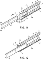
FIG. 11 is a diagram illustrating the second rail being moved toward the channel of the first rail according to the embodiment of the present invention; and -
FIG. 12 is a diagram illustrating the second rail is guided to be mounted to the channel of the first rail by the third guiding portion of the guiding structure according to the embodiment of the present invention. - As shown in
FIG. 3 andFIG. 4 , theslide rail assembly 20 includes afirst rail 22, asecond rail 24 and a guidingstructure 26. Preferably, theslide rail assembly 20 further includes athird rail 28, and thefirst rail 22 is movably mounted between thethird rail 28 and thesecond rail 24. - The
third rail 28 includes a firstlateral wall 28a, a secondlateral wall 28b and acentral wall 28c. Thecentral wall 28c is connected between the firstlateral wall 28a and the secondlateral wall 28b, and the firstlateral wall 28a, the secondlateral wall 28b and thecentral wall 28c cooperatively define arail passage 29. - The
first rail 22 is mounted in therail passage 29 of thethird rail 28. Thefirst rail 22 includes afirst wall 30a, asecond wall 30b and alongitudinal wall 32. Thelongitudinal wall 32 is connected between thefirst wall 30a and thesecond wall 30b. Thefirst wall 30a, thesecond wall 30b and thelongitudinal wall 32 cooperatively define achannel 34, and thechannel 34 has a channel opening 35. - The
second rail 24 is mounted to thechannel 34 of thefirst rail 22. Thesecond rail 24 includes athird wall 36a, afourth wall 36b and aside wall 38. Theside wall 38 is connected between thethird wall 36a and thefourth wall 36b. - The guiding
structure 26 is disposed on thefirst rail 22. The guidingstructure 26 disposed adjacent to the channel opening 35 of thechannel 34 of thefirst rail 22 is illustrative of an example hereinafter. The guidingstructure 26 and thefirst rail 22 can be integrally formed. Alternatively, the guidingstructure 26 is not integrally formed with thefirst rail 22, for example, the guidingstructure 26 is securely connected to thefirst rail 22 in a manner of an ancillary including a rivetedmember 39. The ancillary including a rivetedmember 39 is illustrative, but the present invention is not limited thereto. - As shown in
FIG. 5 , the guidingstructure 26 includes a first guidingportion 40, a second guidingportion 42 and a third guidingportion 44 which can be omitted in the present invention. In the present embodiment, the guidingstructure 26 is illustrative of including the first guidingportion 40, the second guidingportion 42 and the third guidingportion 44, but the present invention is not limited thereto. The first guidingportion 40 and the second guidingportion 42 are disposed on two opposite sides of the third guidingportion 44. Preferably, the first guidingportion 40 and the second guidingportion 42 have substantially identical configuration of structures. - Preferably, the first guiding
portion 40 is disposed adjacent to one of thefirst wall 30a and thesecond wall 30b of thefirst rail 22, e.g., the first guidingportion 40 is disposed adjacent to a front end of thefirst wall 30a. The second guidingportion 42 is disposed adjacent to the other one of thefirst wall 30a and thesecond wall 30b of thefirst rail 22, e.g., the second guidingportion 42 is disposed adjacent to a front end of thesecond wall 30b. Thethird guiding portion 44 is disposed adjacent to a front end of thelongitudinal wall 32 of thefirst rail 22. - Preferably, the first guiding
portion 40 extends from thefirst wall 30a of thefirst rail 22 and is located beyond thechannel opening 35. Thesecond guiding portion 42 extends from thesecond wall 30b of thefirst rail 22 and is located beyond thechannel opening 35. Thethird guiding portion 44 extends from thelongitudinal wall 32 of thefirst rail 22 and is located beyond thechannel opening 35. - As shown in
FIG. 6 , thefirst rail 22 and thethird rail 28 are in a retracted status. Thesecond rail 24 is separate from thechannel 34 of thefirst rail 22 via thechannel opening 35 and is located outside thechannel 34. In other words, thesecond rail 24 is detachable from thefirst rail 22, and the aforesaid detaching mechanism is known to those skilled in the art and omitted herein for simplicity. - As shown in
FIG. 6, FIG. 7 and FIG. 8 , in a first configuration of thefirst rail 22 and thesecond rail 24, when thesecond rail 24 is desired to be mounted to thefirst rail 22 in a direction D, thesecond rail 24 is guided by the first guiding portion 40 (as shown inFIG. 7 ) or the second guiding portion 42 (as shown inFIG. 8 ) of the guidingstructure 26 to allow thesecond rail 24 to be mounted in thechannel 34 of thefirst rail 22 via thechannel opening 35. In addition, thelongitudinal wall 32 of thefirst rail 22 has a longitudinal direction L and a height direction H. Thelongitudinal wall 32 is oriented substantially parallel to the longitudinal direction L. The height direction H is substantially perpendicular to the longitudinal direction L and passes through thefirst wall 30a and thesecond wall 30b of thefirst rail 22. Furthermore, during process of thesecond rail 24 being mounted to thefirst rail 22, the guidingstructure 26 is able to be used for guiding thesecond rail 24 from outside thechannel 34 to inside thechannel 34 in the height direction H which is substantially perpendicular to the longitudinal direction L of thelongitudinal wall 32 of thefirst rail 22. - For example, the first guiding
portion 40 includes an inclined surface or a cambered surface. During the process of thesecond rail 24 being mounted to thefirst rail 22, an end portion of thesecond rail 24 is guided by the first guidingportion 40 of the guidingstructure 26, as shown inFIG. 7 , such that thesecond rail 24 is guided downwards from outside the channel 34 (or outside the channel opening 35) of thefirst rail 22 to approach thechannel 34. One of the advantages of the aforesaid design is to prevent the end portion of thesecond rail 24 from hitting a front end of thefirst wall 30a of thefirst rail 22 or to prevent the end portion of thesecond rail 24 from hitting a front end of the firstlateral wall 28a of thethird rail 28. In addition, the second guidingportion 42 includes an inclined surface or a cambered surface. During the process of thesecond rail 24 being mounted to thefirst rail 22, the end portion of thesecond rail 24 is guided by the second guidingportion 42 of the guidingstructure 26, as shown inFIG. 8 , such that thesecond rail 24 is guided upwards from outside the channel 34 (or outside the channel opening 35) of thefirst rail 22 to approach thechannel 34. One of the advantages of the aforesaid design is to prevent the end portion of thesecond rail 24 from hitting a front end of thesecond wall 30b of thefirst rail 22 or to prevent the end portion of thesecond rail 24 from hitting a front end of the secondlateral wall 28b of thethird rail 28. - As shown in
FIG. 9 and FIG. 10 , after thesecond rail 24 is guided from outside the channel 34 (or from outside of the channel opening 35) of thefirst rail 22 to inside thechannel 34 by the first guidingportion 40 or by the second guidingportion 42, the working process of thesecond rail 24 being mounted to thefirst rail 22 is completed. - As shown in
FIG. 11 and FIG. 12 , thefirst rail 22 and thethird rail 28 are in the retracted status. Thelongitudinal wall 32 of thefirst rail 22 further has a transverse direction S. The transverse direction S is substantially perpendicular to the longitudinal direction L and the height direction H. In a second configuration of thefirst rail 22 and thesecond rail 24, when thesecond rail 24 is desired to be mounted to thefirst rail 22 in the direction D, thesecond rail 24 is guided by the third guidingportion 44 of the guidingstructure 26 to allow thesecond rail 24 to be mounted in thechannel 34 of thefirst rail 22 via thechannel opening 35. Furthermore, during the process of thesecond rail 24 being mounted to thefirst rail 22, the guidingstructure 26 is able to be used for guiding thesecond rail 24 from outside thechannel 34 to inside thechannel 34 in the transverse direction S which is substantially perpendicular to the longitudinal direction L of thelongitudinal wall 32 of thefirst rail 22. Preferably, the guidingstructure 26 has anedge 46 adjacent to the third guidingportion 44, and theedge 46 is located in a position substantially corresponding to thecentral wall 28c of thethird rail 28. Furthermore, theedge 46 is located in front of thecentral wall 28c of thethird rail 28. - For example, the third guiding
portion 44 includes an inclined surface or a cambered surface. During the process of thesecond rail 24 being mounted to thefirst rail 22, the end portion of thesecond rail 24 is guided by the third guidingportion 44 of the guidingstructure 26, such that thesecond rail 24 is laterally guided from outside the channel 34 (or outside the channel opening 35) of thefirst rail 22 to approach thechannel 34. One of the advantages of the aforesaid design is to prevent the end portion of thesecond rail 24 from hitting a front end of thelongitudinal wall 32 of thefirst rail 22 or to prevent the end portion of thesecond rail 24 from hitting a front end of thecentral wall 28c of thethird rail 28. - It should be noticed that the third guiding
portion 44 can include a firstinclined surface 440, a secondinclined surface 441 and a thirdinclined surface 442. The firstinclined surface 440 corresponds to theside wall 38 of thesecond rail 24. The secondinclined surface 441 and the thirdinclined surface 442 are disposed on opposite sides of the firstinclined surface 440. The secondinclined surface 441 corresponds to thethird wall 36a of thesecond rail 24. The thirdinclined surface 442 corresponds to thefourth wall 36b of thesecond rail 24. During the process of thesecond rail 24 being mounted to thefirst rail 22, the firstinclined surface 440, the secondinclined surface 441 and the thirdinclined surface 442 may laterally guide theside wall 38, thethird wall 36a and thefourth wall 36b, so as to enhance the guiding effect of the third guidingportion 44 on the end of thesecond rail 24 and thus to facilitate thesecond rail 24 to be mounted to thefirst rail 22. - In addition, the present invention further provides a mounting method for slide rails. The mounting method includes providing a
first rail 22 with alongitudinal wall 32. Thelongitudinal wall 32 is oriented substantially parallel to a longitudinal direction L. Thefirst rail 22 includes achannel 34. The mounting method further includes providing a guidingstructure 26 to be disposed on thefirst rail 22 and providing asecond rail 24. The guidingstructure 26 guides thesecond rail 24 into thechannel 34 of thefirst rail 22 in at least one of a height direction H and a transverse direction S, wherein the longitudinal direction L, the height direction H and the transverse direction S are substantially perpendicular to one another. The detailed descriptions for the mounting method are illustrated in the above-mentioned paragraphs and omitted herein for simplicity. - Compared to the prior art, the slide rail assembly has advantages over the prior art by the following perspectives:
- 1. The guiding
structure 26 facilitates thesecond rail 24 to be mounted to thefirst rail 22 from outside thechannel 34 to inside thechannel 34. - 2. The guiding
structure 26 is able to guide thesecond rail 24 into thechannel 34 of thefirst rail 22 in a direction different from the longitudinal direction L (e.g., the height direction H or the transverse direction S).
Claims (15)
- A slide rail assembly (20), comprising:a first rail (22) comprising a first wall (30a), a second wall (30b) and a longitudinal wall (32) connected between the first wall (30a) and the second wall (30b), the first wall (30a), the second wall (30b) and the longitudinal wall (32) cooperatively defining a channel (34), the channel (34) having a channel opening (35);a second rail (24); andcharacterized by:a guiding structure (26) disposed adjacent to the channel opening (35) of the channel (34) and for guiding the second rail (24) to be mounted into the channel (34) via the channel opening (35).
- The slide rail assembly (20) of claim 1, characterized in that the guiding structure (26) comprises a first guiding portion (40), and the first guiding portion (40) is disposed adjacent to one of the first wall (30a) and the second wall (30b).
- The slide rail assembly (20) of claim 2, characterized in that the first guiding portion (40) extends from one of the first wall (30a) and the second wall (30b) and is located beyond the channel opening (35).
- The slide rail assembly (20) of claim 3, characterized in that the guiding structure (26) further comprises a second guiding portion (42), and the second guiding portion (42) is disposed adjacent to the other one of the first wall (30a) and the second wall (30b).
- The slide rail assembly (20) of claim4, characterized in that the second guiding portion (42) extends from the other one of the first wall (30a) and the second wall (30b) and is located beyond the channel opening (35).
- The slide rail assembly (20) of claims4 or 5, characterized in that the guiding structure (26) comprises a third guiding portion (44), and the third guiding portion (44) is disposed adjacent to the longitudinal wall (32), the third guiding portion (44) extends from the longitudinal wall (32) and is located beyond the channel opening (35).
- The slide rail assembly (20) of claim 6, characterized in that at least one of the first guiding portion (40), the second guiding portion (42) and the third guiding portion (44) comprises an inclined surface or a cambered surface.
- The slide rail assembly (20) of claims 1-7, further characterized by a third rail (28), the first rail (22) being mounted between the third rail (28) and the second rail (24), the third rail (28) comprises a first lateral wall (28a), a second lateral wall (28b) and a central wall (28c) connected between the first lateral wall (28a) and the second lateral wall (28b), the guiding structure (26) has an edge, and the edge is in a position substantially corresponding to the central wall (28c) of the third rail (28).
- A slide rail assembly (20), comprising:a first rail (22) comprising a first wall (30a), a second wall (30b) and a longitudinal wall (32), the longitudinal wall (32) having a longitudinal direction (L), a height direction (H) and a transverse direction (S) and being connected between the first wall (30a) and the second wall (30b), the longitudinal wall (32) being oriented substantially parallel to the longitudinal direction (L), the height direction (H) being substantially perpendicular to the longitudinal direction (L) and passing through the first wall (30a) and the second wall (30b), the transverse direction (S) being substantially perpendicular to the longitudinal direction (L) and the height direction (H), the first wall (30a), the second wall (30b) and the longitudinal wall (32) cooperatively defining a channel (34);a second rail (24); andcharacterized by:a guiding structure (26) disposed on the first rail (22), the guiding structure (26) being for guiding the second rail (24) from outside the channel (34) to inside the channel (34) in at least one of the height direction (H) and the transverse direction (S) of the longitudinal wall (32), so that the second rail (24) is mounted to the first rail (22).
- The slide rail assembly (20) of claim9, characterized in that the guiding structure (26) comprises a first guiding portion (40), and the first guiding portion (40) is disposed adjacent to one of the first wall (30a) and the second wall (30b).
- The slide rail assembly (20) of claim 10, characterized in that the guiding structure (26) further comprises a second guiding portion (42), and the second guiding portion (42) is disposed adjacent to the other one of the first wall (30a) and the second wall (30b).
- The slide rail assembly (20) of claim 11, characterized in that the guiding structure (26) comprises a third guiding portion (44), and the third guiding portion (44) is disposed adjacent to the longitudinal wall (32).
- The slide rail assembly (20) of claim 12, characterized in that at least one of the first guiding portion (40), the second guiding portion (42) and the third guiding portion (44) comprises an inclined surface or a cambered surface.
- The slide rail assembly (20) of claim 9-13, further comprising a third rail (28), the first rail (22) being mounted between the third rail (28) and the second rail (24).
- A mounting method for slide rails, comprising:providing a first rail (22) with a longitudinal wall (32) oriented substantially parallel to a longitudinal direction (L), the first rail (22) comprises a channel (34);characterized by:providing a guiding structure (26) to be disposed on the first rail (22); andproviding a second rail (24), the guiding structure (26) guiding the second rail (24) into the channel (34) of the first rail (22) in at least one of a height direction (H) and a transverse direction (S), wherein the longitudinal direction (L), the height direction (H) and the transverse direction (S) are substantially perpendicular to one another.
Applications Claiming Priority (1)
| Application Number | Priority Date | Filing Date | Title |
|---|---|---|---|
| TW106129416A TWI633829B (en) | 2017-08-28 | 2017-08-28 | Slide rail assembly and mounting method for slide rails |
Publications (2)
| Publication Number | Publication Date |
|---|---|
| EP3451808A1 true EP3451808A1 (en) | 2019-03-06 |
| EP3451808B1 EP3451808B1 (en) | 2020-12-09 |
Family
ID=61258144
Family Applications (1)
| Application Number | Title | Priority Date | Filing Date |
|---|---|---|---|
| EP18157396.5A Active EP3451808B1 (en) | 2017-08-28 | 2018-02-19 | Slide rail assembly and mounting method for slide rails |
Country Status (4)
| Country | Link |
|---|---|
| US (1) | US10260556B2 (en) |
| EP (1) | EP3451808B1 (en) |
| JP (1) | JP6669797B2 (en) |
| TW (1) | TWI633829B (en) |
Cited By (2)
| Publication number | Priority date | Publication date | Assignee | Title |
|---|---|---|---|---|
| EP3911135A1 (en) * | 2020-05-12 | 2021-11-17 | King Slide Works Co., Ltd. | Slide rail assembly |
| EP4087375A1 (en) * | 2021-05-04 | 2022-11-09 | King Slide Works Co., Ltd. | Slide rail assembly and slide rail kit thereof |
Families Citing this family (6)
| Publication number | Priority date | Publication date | Assignee | Title |
|---|---|---|---|---|
| US11633042B2 (en) * | 2020-05-12 | 2023-04-25 | Tenn-Tex Plastics, Inc. | Bracket for ball bearing drawer slide |
| TWI733625B (en) * | 2020-11-24 | 2021-07-11 | 川湖科技股份有限公司 | Slide rail assembly |
| JP2022103748A (en) * | 2020-12-28 | 2022-07-08 | 京セラドキュメントソリューションズ株式会社 | Slide rail and image forming device |
| CN115306823B (en) * | 2021-05-08 | 2024-06-14 | 川湖科技股份有限公司 | Slide rail assembly and slide rail kit |
| TWI760286B (en) | 2021-09-29 | 2022-04-01 | 川湖科技股份有限公司 | Slide rail assembly |
| TWI892780B (en) * | 2024-08-02 | 2025-08-01 | 富世達股份有限公司 | Slide rail device |
Citations (3)
| Publication number | Priority date | Publication date | Assignee | Title |
|---|---|---|---|---|
| US20150084494A1 (en) * | 2013-09-26 | 2015-03-26 | Innovation First, Inc. | Sliding rack-mountable rails for rack-mountable components |
| EP3057386A1 (en) * | 2015-02-13 | 2016-08-17 | King Slide Works Co., Ltd. | Slide rail assembly |
| EP3144457A1 (en) * | 2015-09-18 | 2017-03-22 | King Slide Works Co., Ltd. | Slide rail assembly with interlock device |
Family Cites Families (17)
| Publication number | Priority date | Publication date | Assignee | Title |
|---|---|---|---|---|
| JPS527230U (en) * | 1975-06-30 | 1977-01-19 | ||
| JPS52160528U (en) * | 1976-05-31 | 1977-12-06 | ||
| CH676318A5 (en) * | 1988-03-23 | 1991-01-15 | Agenda Anstalt | |
| FR2665062B1 (en) * | 1990-07-30 | 1994-09-16 | Ergam Roneo | DRAWER STORAGE BOX FOR OFFICES. |
| US5785400A (en) * | 1995-11-01 | 1998-07-28 | Sauder Woodworking Co. | Dual drawer slide assembly |
| US5876103A (en) * | 1996-06-05 | 1999-03-02 | Grass America, Inc. | Self-positioning cabinet rail for a drawer guide |
| TW491056U (en) * | 2001-01-08 | 2002-06-11 | Kuo-Chan Weng | Guide structure of extensible rail assembly |
| US6619771B2 (en) * | 2001-12-06 | 2003-09-16 | Grass America, Inc. | Self-positioning cabinet rail for a drawer guide |
| DE10318781A1 (en) * | 2003-04-25 | 2004-11-25 | Schock Metallwerk Gmbh | pull-out guide |
| KR101695808B1 (en) * | 2009-07-22 | 2017-01-13 | 엘지전자 주식회사 | A refrigerator |
| US8186779B2 (en) | 2009-12-08 | 2012-05-29 | King Slide Works Co., Ltd. | Slide assembly with security device |
| US8297723B2 (en) * | 2011-01-21 | 2012-10-30 | King Slide Works Co., Ltd. | Interlock device for slide assembly |
| US8780565B2 (en) | 2011-02-22 | 2014-07-15 | Dell Products L.P. | Information handling system slide rail alignment support |
| US8282176B1 (en) * | 2011-06-10 | 2012-10-09 | King Slide Works Co., Ltd. | Slide assembly having locking mechanism |
| US9033434B2 (en) * | 2013-09-30 | 2015-05-19 | Sauder Woodworking Co. | Drawer glide |
| TWI607721B (en) * | 2015-12-04 | 2017-12-11 | 川湖科技股份有限公司 | Slide rail assembly |
| TWI584761B (en) * | 2016-09-13 | 2017-06-01 | 川湖科技股份有限公司 | Slide rail assembly |
-
2017
- 2017-08-28 TW TW106129416A patent/TWI633829B/en active
-
2018
- 2018-01-11 US US15/868,992 patent/US10260556B2/en active Active
- 2018-02-19 EP EP18157396.5A patent/EP3451808B1/en active Active
- 2018-03-28 JP JP2018061039A patent/JP6669797B2/en active Active
Patent Citations (3)
| Publication number | Priority date | Publication date | Assignee | Title |
|---|---|---|---|---|
| US20150084494A1 (en) * | 2013-09-26 | 2015-03-26 | Innovation First, Inc. | Sliding rack-mountable rails for rack-mountable components |
| EP3057386A1 (en) * | 2015-02-13 | 2016-08-17 | King Slide Works Co., Ltd. | Slide rail assembly |
| EP3144457A1 (en) * | 2015-09-18 | 2017-03-22 | King Slide Works Co., Ltd. | Slide rail assembly with interlock device |
Cited By (4)
| Publication number | Priority date | Publication date | Assignee | Title |
|---|---|---|---|---|
| EP3911135A1 (en) * | 2020-05-12 | 2021-11-17 | King Slide Works Co., Ltd. | Slide rail assembly |
| US11213124B2 (en) | 2020-05-12 | 2022-01-04 | King Slide Works Co., Ltd. | Slide rail assembly and rails mounting method thereof |
| EP4087375A1 (en) * | 2021-05-04 | 2022-11-09 | King Slide Works Co., Ltd. | Slide rail assembly and slide rail kit thereof |
| US11730265B2 (en) | 2021-05-04 | 2023-08-22 | King Slide Works Co., Ltd. | Slide rail assembly and slide rail kit thereof |
Also Published As
| Publication number | Publication date |
|---|---|
| EP3451808B1 (en) | 2020-12-09 |
| US20190063493A1 (en) | 2019-02-28 |
| TWI633829B (en) | 2018-08-21 |
| US10260556B2 (en) | 2019-04-16 |
| JP2019037749A (en) | 2019-03-14 |
| JP6669797B2 (en) | 2020-03-18 |
| TW201914399A (en) | 2019-04-01 |
Similar Documents
| Publication | Publication Date | Title |
|---|---|---|
| US10260556B2 (en) | Slide rail assembly and mounting method for slide rails | |
| US9723746B2 (en) | Slide rail assembly | |
| US20110043087A1 (en) | Slide rail buffering structure | |
| US10159164B2 (en) | Suspension type sliding bracket having anti-dropping mechanism | |
| US9572277B2 (en) | Slide rail assembly | |
| US10641038B2 (en) | Rail for an architectural opening covering | |
| US9681573B2 (en) | Slide rail assembly | |
| US20160029791A1 (en) | Slide rail assembly | |
| EP3324714B1 (en) | Supporting device for rail member | |
| US9247815B2 (en) | Slide rail assembly | |
| EP3397035B1 (en) | Slide rail assembly | |
| EP3457826A1 (en) | Rack system and slide rail assembly thereof | |
| US10117352B2 (en) | Slide rail assembly | |
| JPWO2016027340A1 (en) | Slider for slide fastener | |
| EP3273757A1 (en) | Slide rail assembly for rack system | |
| EP2893838A1 (en) | Adjustable bracket assembly and slide assembly comprising the same | |
| CN102711557B (en) | Retracting device for drawers | |
| EP3911135A1 (en) | Slide rail assembly | |
| CN109419192A (en) | Slide rail assembly and slide rail mounting method | |
| TWI565396B (en) | Slide rail assembly | |
| CN106714499A (en) | Sliding rail assembly | |
| CN108338557A (en) | Sliding rail assembly | |
| CN105078028B (en) | Drawer sliding rail assembly | |
| EP2921076B1 (en) | Slide rail assembly | |
| CN114190716B (en) | A guide rail with adjustable locking force |
Legal Events
| Date | Code | Title | Description |
|---|---|---|---|
| PUAI | Public reference made under article 153(3) epc to a published international application that has entered the european phase |
Free format text: ORIGINAL CODE: 0009012 |
|
| STAA | Information on the status of an ep patent application or granted ep patent |
Free format text: STATUS: THE APPLICATION HAS BEEN PUBLISHED |
|
| AK | Designated contracting states |
Kind code of ref document: A1 Designated state(s): AL AT BE BG CH CY CZ DE DK EE ES FI FR GB GR HR HU IE IS IT LI LT LU LV MC MK MT NL NO PL PT RO RS SE SI SK SM TR |
|
| AX | Request for extension of the european patent |
Extension state: BA ME |
|
| STAA | Information on the status of an ep patent application or granted ep patent |
Free format text: STATUS: REQUEST FOR EXAMINATION WAS MADE |
|
| 17P | Request for examination filed |
Effective date: 20190314 |
|
| RBV | Designated contracting states (corrected) |
Designated state(s): AL AT BE BG CH CY CZ DE DK EE ES FI FR GB GR HR HU IE IS IT LI LT LU LV MC MK MT NL NO PL PT RO RS SE SI SK SM TR |
|
| GRAP | Despatch of communication of intention to grant a patent |
Free format text: ORIGINAL CODE: EPIDOSNIGR1 |
|
| STAA | Information on the status of an ep patent application or granted ep patent |
Free format text: STATUS: GRANT OF PATENT IS INTENDED |
|
| INTG | Intention to grant announced |
Effective date: 20200708 |
|
| GRAS | Grant fee paid |
Free format text: ORIGINAL CODE: EPIDOSNIGR3 |
|
| GRAA | (expected) grant |
Free format text: ORIGINAL CODE: 0009210 |
|
| STAA | Information on the status of an ep patent application or granted ep patent |
Free format text: STATUS: THE PATENT HAS BEEN GRANTED |
|
| AK | Designated contracting states |
Kind code of ref document: B1 Designated state(s): AL AT BE BG CH CY CZ DE DK EE ES FI FR GB GR HR HU IE IS IT LI LT LU LV MC MK MT NL NO PL PT RO RS SE SI SK SM TR |
|
| REG | Reference to a national code |
Ref country code: GB Ref legal event code: FG4D |
|
| REG | Reference to a national code |
Ref country code: AT Ref legal event code: REF Ref document number: 1344698 Country of ref document: AT Kind code of ref document: T Effective date: 20201215 Ref country code: CH Ref legal event code: EP |
|
| REG | Reference to a national code |
Ref country code: DE Ref legal event code: R096 Ref document number: 602018010503 Country of ref document: DE |
|
| REG | Reference to a national code |
Ref country code: IE Ref legal event code: FG4D |
|
| PG25 | Lapsed in a contracting state [announced via postgrant information from national office to epo] |
Ref country code: RS Free format text: LAPSE BECAUSE OF FAILURE TO SUBMIT A TRANSLATION OF THE DESCRIPTION OR TO PAY THE FEE WITHIN THE PRESCRIBED TIME-LIMIT Effective date: 20201209 Ref country code: FI Free format text: LAPSE BECAUSE OF FAILURE TO SUBMIT A TRANSLATION OF THE DESCRIPTION OR TO PAY THE FEE WITHIN THE PRESCRIBED TIME-LIMIT Effective date: 20201209 Ref country code: NO Free format text: LAPSE BECAUSE OF FAILURE TO SUBMIT A TRANSLATION OF THE DESCRIPTION OR TO PAY THE FEE WITHIN THE PRESCRIBED TIME-LIMIT Effective date: 20210309 Ref country code: GR Free format text: LAPSE BECAUSE OF FAILURE TO SUBMIT A TRANSLATION OF THE DESCRIPTION OR TO PAY THE FEE WITHIN THE PRESCRIBED TIME-LIMIT Effective date: 20210310 |
|
| REG | Reference to a national code |
Ref country code: AT Ref legal event code: MK05 Ref document number: 1344698 Country of ref document: AT Kind code of ref document: T Effective date: 20201209 |
|
| PG25 | Lapsed in a contracting state [announced via postgrant information from national office to epo] |
Ref country code: BG Free format text: LAPSE BECAUSE OF FAILURE TO SUBMIT A TRANSLATION OF THE DESCRIPTION OR TO PAY THE FEE WITHIN THE PRESCRIBED TIME-LIMIT Effective date: 20210309 Ref country code: LV Free format text: LAPSE BECAUSE OF FAILURE TO SUBMIT A TRANSLATION OF THE DESCRIPTION OR TO PAY THE FEE WITHIN THE PRESCRIBED TIME-LIMIT Effective date: 20201209 Ref country code: SE Free format text: LAPSE BECAUSE OF FAILURE TO SUBMIT A TRANSLATION OF THE DESCRIPTION OR TO PAY THE FEE WITHIN THE PRESCRIBED TIME-LIMIT Effective date: 20201209 |
|
| REG | Reference to a national code |
Ref country code: NL Ref legal event code: MP Effective date: 20201209 |
|
| PG25 | Lapsed in a contracting state [announced via postgrant information from national office to epo] |
Ref country code: NL Free format text: LAPSE BECAUSE OF FAILURE TO SUBMIT A TRANSLATION OF THE DESCRIPTION OR TO PAY THE FEE WITHIN THE PRESCRIBED TIME-LIMIT Effective date: 20201209 Ref country code: HR Free format text: LAPSE BECAUSE OF FAILURE TO SUBMIT A TRANSLATION OF THE DESCRIPTION OR TO PAY THE FEE WITHIN THE PRESCRIBED TIME-LIMIT Effective date: 20201209 |
|
| REG | Reference to a national code |
Ref country code: LT Ref legal event code: MG9D |
|
| PG25 | Lapsed in a contracting state [announced via postgrant information from national office to epo] |
Ref country code: LT Free format text: LAPSE BECAUSE OF FAILURE TO SUBMIT A TRANSLATION OF THE DESCRIPTION OR TO PAY THE FEE WITHIN THE PRESCRIBED TIME-LIMIT Effective date: 20201209 Ref country code: CZ Free format text: LAPSE BECAUSE OF FAILURE TO SUBMIT A TRANSLATION OF THE DESCRIPTION OR TO PAY THE FEE WITHIN THE PRESCRIBED TIME-LIMIT Effective date: 20201209 Ref country code: EE Free format text: LAPSE BECAUSE OF FAILURE TO SUBMIT A TRANSLATION OF THE DESCRIPTION OR TO PAY THE FEE WITHIN THE PRESCRIBED TIME-LIMIT Effective date: 20201209 Ref country code: SM Free format text: LAPSE BECAUSE OF FAILURE TO SUBMIT A TRANSLATION OF THE DESCRIPTION OR TO PAY THE FEE WITHIN THE PRESCRIBED TIME-LIMIT Effective date: 20201209 Ref country code: PT Free format text: LAPSE BECAUSE OF FAILURE TO SUBMIT A TRANSLATION OF THE DESCRIPTION OR TO PAY THE FEE WITHIN THE PRESCRIBED TIME-LIMIT Effective date: 20210409 Ref country code: RO Free format text: LAPSE BECAUSE OF FAILURE TO SUBMIT A TRANSLATION OF THE DESCRIPTION OR TO PAY THE FEE WITHIN THE PRESCRIBED TIME-LIMIT Effective date: 20201209 Ref country code: SK Free format text: LAPSE BECAUSE OF FAILURE TO SUBMIT A TRANSLATION OF THE DESCRIPTION OR TO PAY THE FEE WITHIN THE PRESCRIBED TIME-LIMIT Effective date: 20201209 |
|
| PG25 | Lapsed in a contracting state [announced via postgrant information from national office to epo] |
Ref country code: AT Free format text: LAPSE BECAUSE OF FAILURE TO SUBMIT A TRANSLATION OF THE DESCRIPTION OR TO PAY THE FEE WITHIN THE PRESCRIBED TIME-LIMIT Effective date: 20201209 Ref country code: PL Free format text: LAPSE BECAUSE OF FAILURE TO SUBMIT A TRANSLATION OF THE DESCRIPTION OR TO PAY THE FEE WITHIN THE PRESCRIBED TIME-LIMIT Effective date: 20201209 |
|
| REG | Reference to a national code |
Ref country code: DE Ref legal event code: R097 Ref document number: 602018010503 Country of ref document: DE |
|
| PG25 | Lapsed in a contracting state [announced via postgrant information from national office to epo] |
Ref country code: MC Free format text: LAPSE BECAUSE OF FAILURE TO SUBMIT A TRANSLATION OF THE DESCRIPTION OR TO PAY THE FEE WITHIN THE PRESCRIBED TIME-LIMIT Effective date: 20201209 Ref country code: IS Free format text: LAPSE BECAUSE OF FAILURE TO SUBMIT A TRANSLATION OF THE DESCRIPTION OR TO PAY THE FEE WITHIN THE PRESCRIBED TIME-LIMIT Effective date: 20210409 |
|
| PLBE | No opposition filed within time limit |
Free format text: ORIGINAL CODE: 0009261 |
|
| STAA | Information on the status of an ep patent application or granted ep patent |
Free format text: STATUS: NO OPPOSITION FILED WITHIN TIME LIMIT |
|
| REG | Reference to a national code |
Ref country code: BE Ref legal event code: MM Effective date: 20210228 |
|
| PG25 | Lapsed in a contracting state [announced via postgrant information from national office to epo] |
Ref country code: LI Free format text: LAPSE BECAUSE OF NON-PAYMENT OF DUE FEES Effective date: 20210228 Ref country code: IT Free format text: LAPSE BECAUSE OF FAILURE TO SUBMIT A TRANSLATION OF THE DESCRIPTION OR TO PAY THE FEE WITHIN THE PRESCRIBED TIME-LIMIT Effective date: 20201209 Ref country code: LU Free format text: LAPSE BECAUSE OF NON-PAYMENT OF DUE FEES Effective date: 20210219 Ref country code: CH Free format text: LAPSE BECAUSE OF NON-PAYMENT OF DUE FEES Effective date: 20210228 Ref country code: AL Free format text: LAPSE BECAUSE OF FAILURE TO SUBMIT A TRANSLATION OF THE DESCRIPTION OR TO PAY THE FEE WITHIN THE PRESCRIBED TIME-LIMIT Effective date: 20201209 |
|
| 26N | No opposition filed |
Effective date: 20210910 |
|
| PG25 | Lapsed in a contracting state [announced via postgrant information from national office to epo] |
Ref country code: SI Free format text: LAPSE BECAUSE OF FAILURE TO SUBMIT A TRANSLATION OF THE DESCRIPTION OR TO PAY THE FEE WITHIN THE PRESCRIBED TIME-LIMIT Effective date: 20201209 Ref country code: DK Free format text: LAPSE BECAUSE OF FAILURE TO SUBMIT A TRANSLATION OF THE DESCRIPTION OR TO PAY THE FEE WITHIN THE PRESCRIBED TIME-LIMIT Effective date: 20201209 |
|
| PG25 | Lapsed in a contracting state [announced via postgrant information from national office to epo] |
Ref country code: ES Free format text: LAPSE BECAUSE OF FAILURE TO SUBMIT A TRANSLATION OF THE DESCRIPTION OR TO PAY THE FEE WITHIN THE PRESCRIBED TIME-LIMIT Effective date: 20201209 Ref country code: FR Free format text: LAPSE BECAUSE OF NON-PAYMENT OF DUE FEES Effective date: 20210228 |
|
| PG25 | Lapsed in a contracting state [announced via postgrant information from national office to epo] |
Ref country code: IS Free format text: LAPSE BECAUSE OF FAILURE TO SUBMIT A TRANSLATION OF THE DESCRIPTION OR TO PAY THE FEE WITHIN THE PRESCRIBED TIME-LIMIT Effective date: 20210409 |
|
| PG25 | Lapsed in a contracting state [announced via postgrant information from national office to epo] |
Ref country code: BE Free format text: LAPSE BECAUSE OF NON-PAYMENT OF DUE FEES Effective date: 20210228 |
|
| PG25 | Lapsed in a contracting state [announced via postgrant information from national office to epo] |
Ref country code: CY Free format text: LAPSE BECAUSE OF FAILURE TO SUBMIT A TRANSLATION OF THE DESCRIPTION OR TO PAY THE FEE WITHIN THE PRESCRIBED TIME-LIMIT Effective date: 20201209 |
|
| PG25 | Lapsed in a contracting state [announced via postgrant information from national office to epo] |
Ref country code: HU Free format text: LAPSE BECAUSE OF FAILURE TO SUBMIT A TRANSLATION OF THE DESCRIPTION OR TO PAY THE FEE WITHIN THE PRESCRIBED TIME-LIMIT; INVALID AB INITIO Effective date: 20180219 |
|
| PG25 | Lapsed in a contracting state [announced via postgrant information from national office to epo] |
Ref country code: MK Free format text: LAPSE BECAUSE OF FAILURE TO SUBMIT A TRANSLATION OF THE DESCRIPTION OR TO PAY THE FEE WITHIN THE PRESCRIBED TIME-LIMIT Effective date: 20201209 |
|
| REG | Reference to a national code |
Ref country code: DE Ref legal event code: R082 Ref document number: 602018010503 Country of ref document: DE Representative=s name: STRAUS, ALEXANDER, DIPL.-CHEM.UNIV. DR.PHIL., DE |
|
| PG25 | Lapsed in a contracting state [announced via postgrant information from national office to epo] |
Ref country code: MT Free format text: LAPSE BECAUSE OF FAILURE TO SUBMIT A TRANSLATION OF THE DESCRIPTION OR TO PAY THE FEE WITHIN THE PRESCRIBED TIME-LIMIT Effective date: 20201209 |
|
| PG25 | Lapsed in a contracting state [announced via postgrant information from national office to epo] |
Ref country code: TR Free format text: LAPSE BECAUSE OF FAILURE TO SUBMIT A TRANSLATION OF THE DESCRIPTION OR TO PAY THE FEE WITHIN THE PRESCRIBED TIME-LIMIT Effective date: 20201209 |
|
| PGFP | Annual fee paid to national office [announced via postgrant information from national office to epo] |
Ref country code: GB Payment date: 20251208 Year of fee payment: 9 |
|
| PGFP | Annual fee paid to national office [announced via postgrant information from national office to epo] |
Ref country code: IE Payment date: 20251208 Year of fee payment: 9 |
|
| PGFP | Annual fee paid to national office [announced via postgrant information from national office to epo] |
Ref country code: DE Payment date: 20251211 Year of fee payment: 9 |