EP3451694A1 - Vehicle installation structure comprising a loudspeaker device and vehicle structure comprising same - Google Patents
Vehicle installation structure comprising a loudspeaker device and vehicle structure comprising same Download PDFInfo
- Publication number
- EP3451694A1 EP3451694A1 EP17188283.0A EP17188283A EP3451694A1 EP 3451694 A1 EP3451694 A1 EP 3451694A1 EP 17188283 A EP17188283 A EP 17188283A EP 3451694 A1 EP3451694 A1 EP 3451694A1
- Authority
- EP
- European Patent Office
- Prior art keywords
- vehicle
- air duct
- air
- terminal
- diaphragm
- Prior art date
- Legal status (The legal status is an assumption and is not a legal conclusion. Google has not performed a legal analysis and makes no representation as to the accuracy of the status listed.)
- Granted
Links
Images


Classifications
-
- H—ELECTRICITY
- H04—ELECTRIC COMMUNICATION TECHNIQUE
- H04R—LOUDSPEAKERS, MICROPHONES, GRAMOPHONE PICK-UPS OR LIKE ACOUSTIC ELECTROMECHANICAL TRANSDUCERS; ELECTRIC HEARING AIDS; PUBLIC ADDRESS SYSTEMS
- H04R1/00—Details of transducers, loudspeakers or microphones
- H04R1/20—Arrangements for obtaining desired frequency or directional characteristics
- H04R1/22—Arrangements for obtaining desired frequency or directional characteristics for obtaining desired frequency characteristic only
- H04R1/28—Transducer mountings or enclosures modified by provision of mechanical or acoustic impedances, e.g. resonator, damping means
- H04R1/2869—Reduction of undesired resonances, i.e. standing waves within enclosure, or of undesired vibrations, i.e. of the enclosure itself
- H04R1/2873—Reduction of undesired resonances, i.e. standing waves within enclosure, or of undesired vibrations, i.e. of the enclosure itself for loudspeaker transducers
-
- H—ELECTRICITY
- H04—ELECTRIC COMMUNICATION TECHNIQUE
- H04R—LOUDSPEAKERS, MICROPHONES, GRAMOPHONE PICK-UPS OR LIKE ACOUSTIC ELECTROMECHANICAL TRANSDUCERS; ELECTRIC HEARING AIDS; PUBLIC ADDRESS SYSTEMS
- H04R2499/00—Aspects covered by H04R or H04S not otherwise provided for in their subgroups
- H04R2499/10—General applications
- H04R2499/13—Acoustic transducers and sound field adaptation in vehicles
Definitions
- the present invention relates to a vehicle installation structure for arranging at a vehicle partition panel and which comprises a loudspeaker device.
- the invention further relates to a vehicle structure comprising a vehicle partition panel and such vehicle installation structure, and to a vehicle comprising such vehicle structure.
- loudspeaker devices are commonly used for providing audio output to listeners situated in vehicles like cars.
- a loudspeaker device typically employs a magnetic driving unit causing a diaphragm connected to a frame of the loudspeaker device to move back and forth. This vibration creates sound that is produced by the loudspeaker.
- the frame is commonly enclosed by a housing of the loudspeaker device.
- the loudspeaker device is a subwoofer, typically an air communication duct connects an inner space of the housing to an outside space.
- such loudspeaker device is installed at a vehicle panel (such as a vehicle body) which has a separate opening to an outside space of the vehicle.
- the loudspeaker device comprises a housing including an air volume which is communicated at a backside of the diaphragm through an air communication duct and the opening with the outside space of the vehicle.
- Such arrangement enables the loudspeaker device to be placed in small locations such as in a vehicle side space adjacent to a vehicle panel.
- an opening needs to be provided in the vehicle panel, which may form part of the vehicle body.
- such opening is a dedicated hole in a vehicle structure, such as a vehicle panel, which may cause additional noise to enter the vehicle.
- a plug or cover needs to cover such hole, which causes additional costs.
- DE 101 44 786 A1 discloses a vehicle which has a loudspeaker for radiating sound waves into the passenger compartment and an air channel for air conditioning the passenger compartment.
- the air channel has an air channel opening facing the passenger compartment.
- the loudspeaker is mounted in the air channel so that the sound waves can be radiated through the air channel opening into the passenger compartment.
- the back space of the loudspeaker device is connected to the internal air duct of the air conditioning system arranged in or adjacent to the dashboard (i.e. after a ventilation system which introduces the outside air from the outside to the passenger compartment), so that the reversed back sound enters the passenger compartment through the internal air duct.
- This provides the disadvantage that the sound quality deteriorates, particularly if the loudspeaker device is configured to operate in the subwoofer range.
- EP 2 858 377 A1 discloses an in-car audio system including a speaker unit.
- a frame of the speaker unit is fixed to a support plate serving as part of the structural member of a vehicle via a partition wall member.
- the support plate has an opening formed therein.
- a duct is connected to the opening, and the opening communicates with the outside of the vehicle.
- a space surrounded by the speaker unit, the support plate, and a partition wall member serves as a first acoustic resonance space, and a communication channel located inside the duct serves as a second acoustic resonance space.
- the opening is a dedicated hole in the vehicle partition wall member, which causes additional noise to enter the vehicle and decreases the strength of the vehicle partition wall member.
- the present invention is related to a vehicle installation structure, a vehicle structure comprising such vehicle installation structure, and to a vehicle comprising such vehicle structure according to the features of the appended claims.
- a vehicle installation structure comprising an air duct configured to form part of a ventilation system of a vehicle for introducing outside air from an outside space of the vehicle to an inside passenger space of the vehicle.
- the air duct comprises a first terminal for coupling to an opening in a partition panel of the vehicle which separates the outside space from an inner space of the vehicle, and a second terminal for coupling to a fan causing the outside air to flow from the outside space of the vehicle to the inside passenger space of the vehicle.
- a loudspeaker device comprises a driver and a diaphragm, and is configured to emit sound towards the passenger space of the vehicle from a first side of the diaphragm, the loudspeaker device comprising a housing surrounding a second side of the diaphragm opposite the first side and a communication channel which is configured to allow a back chamber of the housing facing the second side of the diaphragm to communicate with the outside space of the vehicle.
- the communication channel of the loudspeaker device is connected to the air duct between the first terminal and the second terminal.
- the loudspeaker device can be arranged in an inside space of the vehicle, preferably close to an opening of the ventilation system to the outside.
- the ventilation system is or includes an air conditioning system.
- the port of the air communication channel of the loudspeaker device may be connected to the duct system of the ventilation system or air conditioning system, respectively.
- the acoustical impedance of the loudspeaker device from the port of the air communication channel to the outside may thus be quite low because the port may be arranged quite close at the opening of the ventilation system or air conditioning system, respectively, to the outside of the vehicle.
- any recirculating ventilation flaps used in the ventilation system the only connection from the front side of the loudspeaker device to the port of the air communication channel of the loudspeaker device at the back side is then through the air ducts of the ventilation system which are, however, quite long. While the front side of the loudspeaker device emits sound into the passenger compartment of the vehicle, the acoustical impedance from the front side of the loudspeaker device to the port of the air communication channel is quite high. Thus, the sound quality of the loudspeaker device is quite well, while a dedicated hole in a vehicle partition wall member, which causes additional noise to enter the vehicle and decreases the strength of the vehicle partition wall member, is not necessary, since the already existing opening of the ventilation system can be used.
- the air duct is configured to form part of an air conditioning system of the vehicle.
- the air communication channel of the loudspeaker device at the back side thereof could be integrated into air channels, boxes, or ducts of the air conditioning system.
- the air duct is integrally formed with, or forms part of, a box of the ventilation system for accommodating the fan. This provides an efficient arrangement while maintaining the advantages as set out above.
- the vehicle installation structure further comprises a recirculating air duct connected to the air duct at a third terminal arranged between the first terminal and the second terminal, a first gating device for regulating an air flow in the air duct between a closed position preventing air to flow in the air duct and an open position enabling air to flow in the air duct, the first gating device disposed in the air duct between the first terminal and the third terminal, and a second gating device disposed in the recirculating air duct for regulating an air flow in the recirculating air duct between a closed position preventing air to flow in the recirculating air duct and an open position enabling air to flow in the recirculating air duct.
- the communication channel of the loudspeaker device is connected to the air duct between the first terminal and the first gating device.
- the diaphragm has a cone shape and is supported by an outer circumferential portion of a frame, wherein the concave side of the diaphragm forms the first side of the diaphragm.
- the loudspeaker device is configured such that the diaphragm vibrates at a frequency in a sub-woofer frequency range. Improved sound quality, and the advantages as described above can be observed particularly for such loudspeaker device.
- the invention also relates to a vehicle structure comprising a vehicle partition panel and a vehicle installation structure as described herein, wherein the air duct is arranged to introduce outside air from the outside space of the vehicle to the inside passenger space of the vehicle through the opening in the vehicle partition panel.
- the invention also relates to a vehicle comprising such vehicle structure.
- the vehicle partition panel forms an outer skin portion of a vehicle body.
- the air duct is positioned in a vehicle compartment in front of the passenger space of the vehicle, in a part of the vehicle beneath or in front of a dashboard of the vehicle, or in the dashboard of the vehicle.
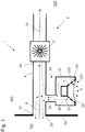
- Fig. 1 shows a vehicle installation structure 1 comprising an air duct 4 of a vehicle ventilation system 2 and a loudspeaker device 20 according to an embodiment of the invention.
- the vehicle installation structure 1 is configured to form a part of a vehicle ventilation system 2.
- vehicle ventilation system 2 is arranged for introducing fresh outside air from an outside space 100 of the vehicle to an inside passenger space 200 of the vehicle, and distributing it inside the passenger space 200, as commonly known in the art.
- such ventilation system 2 comprises at least one fan 3 (typically in the front part of the vehicle body, e.g.
- a ventilation system typically is, or forms part of, a vehicle air conditioning system.
- an air conditioning system comprises a heat exchanger (not shown) by means of which the air moved in the air ducts may be cooled or heated, as is commonly known, but which is not essential for the purposes of the present invention.
- the ventilation system 2 is such air conditioning system.
- air duct 4 forms part of the ventilation system or air conditioning system 2 of the vehicle and is configured for introducing outside air 10 from the outside space 100 of the vehicle to the passenger space 200 of the vehicle.
- the air duct 4 comprises a first terminal 41 coupled to an opening 51 in a partition panel 50 of the vehicle.
- the first terminal 41 is attached to the partition panel 50 such that it is connected to the opening 51 for suctioning outside air into the passenger compartment 200.
- the air duct 4 may be connected to another hollow body which is attached to the partition panel 50.
- the partition panel 50 separates the outside space 100 from an inner space 300 of the vehicle which may be, in principle, any space inside the vehicle body, for example a hollow installation space for any vehicle components or an inner space inside a dashboard.
- the partition panel 50 forms an outer skin portion of the vehicle body.
- it may be a partition panel separating the cabin from the outside of the vehicle.
- An outside space of the vehicle as described herein may encompass, in principle, any space outside the passenger compartment which has access to air outside of the vehicle body (such as the engine compartment which typically is open to the outside at its bottom) and which may be used by the ventilation or air conditioning system for air suctioning of outside air from it into the passenger compartment through an opening in a vehicle partition panel.
- the partition panel 50 may be a part of a multilayer panel structure with two side portions and a hollow space included in between the side portions, wherein the panel 50 as shown in Fig. 1 may form any of the side portions, i.e. an inner side (or skin) portion or an outer side (or skin) portion of such multiple layer panel structure.
- the air duct 4 further comprises a second terminal 42 for coupling to a fan 3.
- the fan 3 causes the outside air 10 to flow from the outside space 100 of the vehicle to the inside passenger space 200 of the vehicle.
- the air duct 4 houses the fan 3, such that the fan 3 is positioned inside the air duct 4 at the second terminal 42.
- the air duct 4 may be any hollow body (such as a circular or rectangular body, e.g. a tube) having a fan located therein at a particular position which is designated herein as the second terminal of the air duct.
- the air duct 4 may be a hollow body (such as a circular or rectangular body, e.g.
- the air duct 4 between the first terminal 41 and second terminal 42 can be any structure which spans a hollow extension between a first location (first terminal 41) and a second location (second terminal 42) and which is appropriate for transporting an air flow in it along the hollow extension.
- first terminal 41 is upstream of the second terminal 42.
- the air duct 4 is an air duct external to the passenger compartment 200. Particularly, it is an air duct which is upstream of the fan 3.
- the air duct 4 forms part of the air conditioning system 2 of the vehicle and may be integrally formed with, or forms part of, a box (so-called climate box) of the air conditioning system 2 for accommodating the fan 3.
- the air duct 4 has the function of a conventional air duct for introducing outside air which is commonly installed in vehicles.
- the opening 51 may be formed as commonly known in vehicle ventilation or air conditioning systems. For example, it has a cover on the outside (not shown) for preventing particles from entering into the air duct 4 and the fan 3.
- the vehicle installation structure 1, particularly the air duct 4 is attached to the vehicle panel 50 or otherwise fixed with respect to the vehicle panel 50.
- the vehicle installation structure 1 further comprises a loudspeaker device 20.
- the loudspeaker device 20 may be a commonly available loudspeaker device and comprises a magnetic driving unit (so-called driver) 22 and a frame 24 connected to the magnetic driving unit 22.
- a housing 21 surrounds and encloses at least a part of the frame 24, to which a diaphragm 23 is attached which is operated by the magnetic driving unit 22 for emitting sound 5 to the inside passenger space 200 of the vehicle from a first side 231 of the diaphragm 23 in accordance with the operation of the magnetic driving unit 22.
- the diaphragm 23 has a cone shape and is supported by an outer circumferential portion of the frame 24, wherein the concave side of the diaphragm 23 forms the first side 231 of the diaphragm.
- the housing 21 surrounds a second side 232 (here: back side 232) of the diaphragm 23 which is opposite the first side 231 (here: front side 231) from which the sound 5 is emitted.
- the diaphragm 23 delimits an inner space 26 of the housing 21 forming an air volume chamber or back chamber facing the back side 232 of the diaphragm 23.
- the back chamber 26 is communicating air to the outside of the housing 21 in accordance with the operation of the magnetic driving unit 22.
- the loudspeaker device 20 comprises a communication channel 25 which is configured to allow the back chamber 26 of the housing 21 to communicate with the outside space 100 of the vehicle.
- the communication channel 25 of the loudspeaker device 20 is connected to the air duct 4 between the first terminal 41 and second terminal 42, i.e. between the opening 51 of the partition panel 50 and the fan 3.
- the loudspeaker device 20 can thus be arranged closely to the opening 51 of the air conditioning system 2 to the outside of the vehicle and is connected to the duct system of the air conditioning system.
- the acoustical impedance of the loudspeaker device 20 from the port of the air communication channel 25 to the outside is thus quite low because the port may be arranged quite close at the opening 51 to the outside of the vehicle.
- the acoustical impedance from the front side 231 of the loudspeaker device to the port of the air communication channel 25 at the air duct 4 is quite high, since for the emitted sound waves 5 the extension of the duct system including the fan 3 of the air conditioning system 2 from the passenger compartment 200 back to the port of the air communication channel 25 is quite long.
- a high amount of reversed back sound 6 is emitted through the opening 51 in the vehicle partition panel 50 to the outside space 100.
- a baffle structure in order to prevent the interference between sound waves 5 radiating from the sound radiating side 231 of the diaphragm 23 to the passenger compartment 200 and opposite-phase sound waves 6 radiating from the opposite side 232 of the diaphragm 23.
- this provides good sound quality, especially when the diaphragm 23 vibrates at a frequency in a sub-woofer frequency range (e.g., at a frequency below 200 Hz).
- Fig. 2 shows a vehicle installation structure with an air duct and a recirculating air duct of a vehicle ventilation system and a loudspeaker device according to a further embodiment of the invention.
- the vehicle installation structure is in most parts similar to the structure according to the embodiment of Fig. 1 , so that the same or similar components thereof have the same reference signs and are not described again. In this respect, it is referred to the above description.
- the structure according to Fig. 2 comprises a recirculating air duct 7 which is connected to the air duct 4 at a third terminal 43 which is arranged between the first terminal 41 and the second terminal 42 as described above.
- a first gating device 31 is disposed in the air duct 4 between the first terminal 41 and the third terminal 43 at the port of the recirculating air duct 7, and is provided for regulating an air flow in the air duct 4 between a closed position and an open position. In the closed position, the first gating device 31 prevents air to flow in the air duct 4. In the open position, the first gating device 31 enables air to flow in the air duct 4.
- the first gating device is any one of a regulating valve, variable blades, flaps, or throttle as commonly used in such automotive ventilation systems for regulating air flow in an air duct.
- a second gating device 32 disposed in the recirculating air duct 7 for regulating an air flow in the recirculating air duct 7 between a closed position preventing air to flow in the recirculating air duct 7 and an open position enabling air to flow in the recirculating air duct 7.
- the second gating device may be implemented similarly as the first gating device.
- the communication channel 25 of the loudspeaker device 20 is connected to the air duct 4 between the first terminal 41 and the first gating device 31.
- the user and/or the air conditioning system 2 itself may switch between introducing fresh air into the passenger compartment 200 or recirculating of air within the passenger compartment 200, or regulate any states in between, that is partial fresh air and recirculating operation at the same time.
- the structure according to Fig. 2 is shown in a first state of operation in which the first gating device 31 is in open position and the second gating device is in closed position. That is, in this operation state, fresh air 10 is introduced into the passenger compartment 200.
- this operation state from sound perspective the behaviour and sound quality is similar to that according to the embodiment of Fig. 1 since the recirculating air duct 7 is closed for the opposite-phase sound waves 6.
- the only connection from the front side 231 of the diaphragm 23 to the port of the communication channel 25 is through the long air ducts of the air conditioning system 2.
- the fan 3 and the long air ducts function as silencer, and noise and reversed back sound are almost vanished.
- the structure according to Fig. 3 which has the same components as the structure according to Fig. 2 , is shown in a second state of operation in which the first gating device 31 is in closed position and the second gating device is in open position. That is, in this operation state, fresh air 10 is prevented from being introduced into the passenger compartment 200, and the air in the passenger compartment 200 is recirculated through duct 7.
- the gating device 31 is in closed position and acts as a shutter preventing the reversed back sound 6 from entering into the passenger compartment 200 through the air duct 4.
- the first gating device 31 since the first gating device 31 is closed, there is no connection for emitted sound waves between the front side 231 of the diaphragm 23 and the port of the air communication channel 25.
- both gating devices 31, 32 will be partially open. There will be a connection for emitted sound waves between the front side 231 of the diaphragm 23 and the port of the air communication channel 25.
- the front side 231 of the diaphragm 23 emits sound into the passenger compartment 200 and through the partially open gating devices 31, 32 back to the port of the air communication channel 25.
Landscapes
- Health & Medical Sciences (AREA)
- Otolaryngology (AREA)
- Physics & Mathematics (AREA)
- Engineering & Computer Science (AREA)
- Acoustics & Sound (AREA)
- Signal Processing (AREA)
- Fittings On The Vehicle Exterior For Carrying Loads, And Devices For Holding Or Mounting Articles (AREA)
Abstract
Description
- The present invention relates to a vehicle installation structure for arranging at a vehicle partition panel and which comprises a loudspeaker device. The invention further relates to a vehicle structure comprising a vehicle partition panel and such vehicle installation structure, and to a vehicle comprising such vehicle structure.
- In the automotive field, loudspeaker devices are commonly used for providing audio output to listeners situated in vehicles like cars. A loudspeaker device typically employs a magnetic driving unit causing a diaphragm connected to a frame of the loudspeaker device to move back and forth. This vibration creates sound that is produced by the loudspeaker. The frame is commonly enclosed by a housing of the loudspeaker device. When the loudspeaker device is a subwoofer, typically an air communication duct connects an inner space of the housing to an outside space.
- In known arrangements, such loudspeaker device is installed at a vehicle panel (such as a vehicle body) which has a separate opening to an outside space of the vehicle. The loudspeaker device comprises a housing including an air volume which is communicated at a backside of the diaphragm through an air communication duct and the opening with the outside space of the vehicle. Such arrangement enables the loudspeaker device to be placed in small locations such as in a vehicle side space adjacent to a vehicle panel. For connecting the air communication duct to the outside, an opening needs to be provided in the vehicle panel, which may form part of the vehicle body. Typically, such opening is a dedicated hole in a vehicle structure, such as a vehicle panel, which may cause additional noise to enter the vehicle. Further, in a case in which such loudspeaker device is a customer option, when no loudspeaker device is installed, a plug or cover needs to cover such hole, which causes additional costs.
-
DE 101 44 786 A1 discloses a vehicle which has a loudspeaker for radiating sound waves into the passenger compartment and an air channel for air conditioning the passenger compartment. The air channel has an air channel opening facing the passenger compartment. The loudspeaker is mounted in the air channel so that the sound waves can be radiated through the air channel opening into the passenger compartment. In this configuration, the back space of the loudspeaker device is connected to the internal air duct of the air conditioning system arranged in or adjacent to the dashboard (i.e. after a ventilation system which introduces the outside air from the outside to the passenger compartment), so that the reversed back sound enters the passenger compartment through the internal air duct. This provides the disadvantage that the sound quality deteriorates, particularly if the loudspeaker device is configured to operate in the subwoofer range. -
EP 2 858 377 A1 - It is an object of the present invention to provide a vehicle installation structure including a loudspeaker device which is capable of providing good sound quality while helping to reduce additional noise to enter the vehicle and not decrease the strength of a vehicle partition wall member.
- The present invention is related to a vehicle installation structure, a vehicle structure comprising such vehicle installation structure, and to a vehicle comprising such vehicle structure according to the features of the appended claims.
- According to an aspect of the invention, there is provided a vehicle installation structure, comprising an air duct configured to form part of a ventilation system of a vehicle for introducing outside air from an outside space of the vehicle to an inside passenger space of the vehicle. The air duct comprises a first terminal for coupling to an opening in a partition panel of the vehicle which separates the outside space from an inner space of the vehicle, and a second terminal for coupling to a fan causing the outside air to flow from the outside space of the vehicle to the inside passenger space of the vehicle. A loudspeaker device comprises a driver and a diaphragm, and is configured to emit sound towards the passenger space of the vehicle from a first side of the diaphragm, the loudspeaker device comprising a housing surrounding a second side of the diaphragm opposite the first side and a communication channel which is configured to allow a back chamber of the housing facing the second side of the diaphragm to communicate with the outside space of the vehicle. In such configuration, the communication channel of the loudspeaker device is connected to the air duct between the first terminal and the second terminal.
- Advantageously, the loudspeaker device can be arranged in an inside space of the vehicle, preferably close to an opening of the ventilation system to the outside. According to an embodiment, the ventilation system is or includes an air conditioning system. The port of the air communication channel of the loudspeaker device may be connected to the duct system of the ventilation system or air conditioning system, respectively. The acoustical impedance of the loudspeaker device from the port of the air communication channel to the outside may thus be quite low because the port may be arranged quite close at the opening of the ventilation system or air conditioning system, respectively, to the outside of the vehicle.
- If there are provided any recirculating ventilation flaps used in the ventilation system, the only connection from the front side of the loudspeaker device to the port of the air communication channel of the loudspeaker device at the back side is then through the air ducts of the ventilation system which are, however, quite long. While the front side of the loudspeaker device emits sound into the passenger compartment of the vehicle, the acoustical impedance from the front side of the loudspeaker device to the port of the air communication channel is quite high. Thus, the sound quality of the loudspeaker device is quite well, while a dedicated hole in a vehicle partition wall member, which causes additional noise to enter the vehicle and decreases the strength of the vehicle partition wall member, is not necessary, since the already existing opening of the ventilation system can be used.
- According to an embodiment, the air duct is configured to form part of an air conditioning system of the vehicle. For example, the air communication channel of the loudspeaker device at the back side thereof could be integrated into air channels, boxes, or ducts of the air conditioning system.
- According to an embodiment, the air duct is integrally formed with, or forms part of, a box of the ventilation system for accommodating the fan. This provides an efficient arrangement while maintaining the advantages as set out above.
- According to an embodiment, the vehicle installation structure further comprises a recirculating air duct connected to the air duct at a third terminal arranged between the first terminal and the second terminal, a first gating device for regulating an air flow in the air duct between a closed position preventing air to flow in the air duct and an open position enabling air to flow in the air duct, the first gating device disposed in the air duct between the first terminal and the third terminal, and a second gating device disposed in the recirculating air duct for regulating an air flow in the recirculating air duct between a closed position preventing air to flow in the recirculating air duct and an open position enabling air to flow in the recirculating air duct. The communication channel of the loudspeaker device is connected to the air duct between the first terminal and the first gating device.
- According to an embodiment, the diaphragm has a cone shape and is supported by an outer circumferential portion of a frame, wherein the concave side of the diaphragm forms the first side of the diaphragm.
- Preferably, the loudspeaker device is configured such that the diaphragm vibrates at a frequency in a sub-woofer frequency range. Improved sound quality, and the advantages as described above can be observed particularly for such loudspeaker device.
- The invention also relates to a vehicle structure comprising a vehicle partition panel and a vehicle installation structure as described herein, wherein the air duct is arranged to introduce outside air from the outside space of the vehicle to the inside passenger space of the vehicle through the opening in the vehicle partition panel. The invention also relates to a vehicle comprising such vehicle structure.
- According to an embodiment, the vehicle partition panel forms an outer skin portion of a vehicle body.
- According to an embodiment, the air duct is positioned in a vehicle compartment in front of the passenger space of the vehicle, in a part of the vehicle beneath or in front of a dashboard of the vehicle, or in the dashboard of the vehicle.
- Aspects and embodiments of the invention will now be described with reference to the drawings, in which
- Fig. 1
- shows a vehicle installation structure comprising an air duct of a vehicle ventilation system and a loudspeaker device according to an embodiment of the invention,
- Fig. 2
- shows a vehicle installation structure with an air duct and a recirculating air duct of a vehicle ventilation system and a loudspeaker device according to a further embodiment of the invention in a first state of operation,
- Fig. 3
- shows a vehicle installation structure with an air duct and a recirculating air duct of a vehicle ventilation system and a loudspeaker device according to a further embodiment of the invention in a second state of operation.
-
Fig. 1 shows avehicle installation structure 1 comprising anair duct 4 of avehicle ventilation system 2 and aloudspeaker device 20 according to an embodiment of the invention. According to an embodiment, thevehicle installation structure 1 is configured to form a part of avehicle ventilation system 2. Particularly, suchvehicle ventilation system 2 is arranged for introducing fresh outside air from anoutside space 100 of the vehicle to aninside passenger space 200 of the vehicle, and distributing it inside thepassenger space 200, as commonly known in the art. For introducing the outside air into the passenger space (or passenger compartment) 200 which accommodates the seats for the driver and passenger(s),such ventilation system 2 comprises at least one fan 3 (typically in the front part of the vehicle body, e.g. in the dashboard) operating by rotation of blades blowing the air from the outside to the inside of the vehicle along one or more air ducts. Nowadays, a ventilation system typically is, or forms part of, a vehicle air conditioning system. In addition to a conventional ventilation system, an air conditioning system comprises a heat exchanger (not shown) by means of which the air moved in the air ducts may be cooled or heated, as is commonly known, but which is not essential for the purposes of the present invention. In the present embodiment, theventilation system 2 is such air conditioning system. - According to the schematic depiction according to
Fig. 1 ,air duct 4 forms part of the ventilation system orair conditioning system 2 of the vehicle and is configured for introducingoutside air 10 from theoutside space 100 of the vehicle to thepassenger space 200 of the vehicle. Theair duct 4 comprises afirst terminal 41 coupled to anopening 51 in apartition panel 50 of the vehicle. For example, thefirst terminal 41 is attached to thepartition panel 50 such that it is connected to theopening 51 for suctioning outside air into thepassenger compartment 200. According to another embodiment, theair duct 4 may be connected to another hollow body which is attached to thepartition panel 50. Thepartition panel 50 separates theoutside space 100 from aninner space 300 of the vehicle which may be, in principle, any space inside the vehicle body, for example a hollow installation space for any vehicle components or an inner space inside a dashboard. For example, thepartition panel 50 forms an outer skin portion of the vehicle body. In an embodiment, it may be a partition panel separating the cabin from the outside of the vehicle. An outside space of the vehicle as described herein may encompass, in principle, any space outside the passenger compartment which has access to air outside of the vehicle body (such as the engine compartment which typically is open to the outside at its bottom) and which may be used by the ventilation or air conditioning system for air suctioning of outside air from it into the passenger compartment through an opening in a vehicle partition panel. For instance, thepartition panel 50 may be a part of a multilayer panel structure with two side portions and a hollow space included in between the side portions, wherein thepanel 50 as shown inFig. 1 may form any of the side portions, i.e. an inner side (or skin) portion or an outer side (or skin) portion of such multiple layer panel structure. - The
air duct 4 further comprises asecond terminal 42 for coupling to afan 3. Thefan 3 causes theoutside air 10 to flow from theoutside space 100 of the vehicle to theinside passenger space 200 of the vehicle. For example, theair duct 4 houses thefan 3, such that thefan 3 is positioned inside theair duct 4 at thesecond terminal 42. For instance, theair duct 4 may be any hollow body (such as a circular or rectangular body, e.g. a tube) having a fan located therein at a particular position which is designated herein as the second terminal of the air duct. According to another embodiment, theair duct 4 may be a hollow body (such as a circular or rectangular body, e.g. a tube) having thesecond terminal 42 located at a position which is remote from thefirst terminal 41, wherein thesecond terminal 42 is coupled, e.g. connected, to another hollow body which houses or is connected to thefan 3. In principle, theair duct 4 between thefirst terminal 41 and second terminal 42 can be any structure which spans a hollow extension between a first location (first terminal 41) and a second location (second terminal 42) and which is appropriate for transporting an air flow in it along the hollow extension. With respect to the air flow of theoutside air 10, thefirst terminal 41 is upstream of thesecond terminal 42. Theair duct 4 is an air duct external to thepassenger compartment 200. Particularly, it is an air duct which is upstream of thefan 3. - According to an embodiment, the
air duct 4 forms part of theair conditioning system 2 of the vehicle and may be integrally formed with, or forms part of, a box (so-called climate box) of theair conditioning system 2 for accommodating thefan 3. As such, theair duct 4 has the function of a conventional air duct for introducing outside air which is commonly installed in vehicles. Theopening 51 may be formed as commonly known in vehicle ventilation or air conditioning systems. For example, it has a cover on the outside (not shown) for preventing particles from entering into theair duct 4 and thefan 3. In the present embodiment, when installed in the vehicle structure of a vehicle, thevehicle installation structure 1, particularly theair duct 4, is attached to thevehicle panel 50 or otherwise fixed with respect to thevehicle panel 50. - The
vehicle installation structure 1 further comprises aloudspeaker device 20. Theloudspeaker device 20 may be a commonly available loudspeaker device and comprises a magnetic driving unit (so-called driver) 22 and aframe 24 connected to themagnetic driving unit 22. Ahousing 21 surrounds and encloses at least a part of theframe 24, to which adiaphragm 23 is attached which is operated by themagnetic driving unit 22 for emittingsound 5 to theinside passenger space 200 of the vehicle from afirst side 231 of thediaphragm 23 in accordance with the operation of themagnetic driving unit 22. In the present embodiment, thediaphragm 23 has a cone shape and is supported by an outer circumferential portion of theframe 24, wherein the concave side of thediaphragm 23 forms thefirst side 231 of the diaphragm. Thehousing 21 surrounds a second side 232 (here: back side 232) of thediaphragm 23 which is opposite the first side 231 (here: front side 231) from which thesound 5 is emitted. - The
diaphragm 23 delimits aninner space 26 of thehousing 21 forming an air volume chamber or back chamber facing theback side 232 of thediaphragm 23. Theback chamber 26 is communicating air to the outside of thehousing 21 in accordance with the operation of themagnetic driving unit 22. - To this end, the
loudspeaker device 20 comprises acommunication channel 25 which is configured to allow theback chamber 26 of thehousing 21 to communicate with theoutside space 100 of the vehicle. Thecommunication channel 25 of theloudspeaker device 20 is connected to theair duct 4 between thefirst terminal 41 andsecond terminal 42, i.e. between the opening 51 of thepartition panel 50 and thefan 3. - The
loudspeaker device 20 can thus be arranged closely to theopening 51 of theair conditioning system 2 to the outside of the vehicle and is connected to the duct system of the air conditioning system. The acoustical impedance of theloudspeaker device 20 from the port of theair communication channel 25 to the outside is thus quite low because the port may be arranged quite close at theopening 51 to the outside of the vehicle. While thefront side 231 of thediaphragm 23 emits sound into thepassenger compartment 200 of the vehicle, the acoustical impedance from thefront side 231 of the loudspeaker device to the port of theair communication channel 25 at theair duct 4 is quite high, since for the emittedsound waves 5 the extension of the duct system including thefan 3 of theair conditioning system 2 from thepassenger compartment 200 back to the port of theair communication channel 25 is quite long. Thus, a high amount of reversedback sound 6 is emitted through theopening 51 in thevehicle partition panel 50 to theoutside space 100. As such, there is formed a baffle structure in order to prevent the interference betweensound waves 5 radiating from thesound radiating side 231 of thediaphragm 23 to thepassenger compartment 200 and opposite-phase sound waves 6 radiating from theopposite side 232 of thediaphragm 23. As a result, this provides good sound quality, especially when thediaphragm 23 vibrates at a frequency in a sub-woofer frequency range (e.g., at a frequency below 200 Hz). -
Fig. 2 shows a vehicle installation structure with an air duct and a recirculating air duct of a vehicle ventilation system and a loudspeaker device according to a further embodiment of the invention. The vehicle installation structure is in most parts similar to the structure according to the embodiment ofFig. 1 , so that the same or similar components thereof have the same reference signs and are not described again. In this respect, it is referred to the above description. - In addition to the structure as described with reference to
Fig. 1 , the structure according toFig. 2 comprises a recirculatingair duct 7 which is connected to theair duct 4 at a third terminal 43 which is arranged between thefirst terminal 41 and thesecond terminal 42 as described above. Afirst gating device 31 is disposed in theair duct 4 between thefirst terminal 41 and the third terminal 43 at the port of the recirculatingair duct 7, and is provided for regulating an air flow in theair duct 4 between a closed position and an open position. In the closed position, thefirst gating device 31 prevents air to flow in theair duct 4. In the open position, thefirst gating device 31 enables air to flow in theair duct 4. There may also be intermediate positions in which the air flow can be reduced continuously and/or in steps. For example, the first gating device is any one of a regulating valve, variable blades, flaps, or throttle as commonly used in such automotive ventilation systems for regulating air flow in an air duct. - Moreover, there is provided a
second gating device 32 disposed in the recirculatingair duct 7 for regulating an air flow in the recirculatingair duct 7 between a closed position preventing air to flow in the recirculatingair duct 7 and an open position enabling air to flow in the recirculatingair duct 7. Similarly, there may also be intermediate positions in which the air flow in the recirculatingair duct 7 can be reduced continuously and/or in steps. The second gating device may be implemented similarly as the first gating device. Thecommunication channel 25 of theloudspeaker device 20 is connected to theair duct 4 between thefirst terminal 41 and thefirst gating device 31. - With provision of the first and second gating devices, the user and/or the
air conditioning system 2 itself may switch between introducing fresh air into thepassenger compartment 200 or recirculating of air within thepassenger compartment 200, or regulate any states in between, that is partial fresh air and recirculating operation at the same time. - The structure according to
Fig. 2 is shown in a first state of operation in which thefirst gating device 31 is in open position and the second gating device is in closed position. That is, in this operation state,fresh air 10 is introduced into thepassenger compartment 200. In this operation state, from sound perspective the behaviour and sound quality is similar to that according to the embodiment ofFig. 1 since the recirculatingair duct 7 is closed for the opposite-phase sound waves 6. Forclosed gating device 32, the only connection from thefront side 231 of thediaphragm 23 to the port of thecommunication channel 25 is through the long air ducts of theair conditioning system 2. Thefan 3 and the long air ducts function as silencer, and noise and reversed back sound are almost vanished. - The structure according to
Fig. 3 , which has the same components as the structure according toFig. 2 , is shown in a second state of operation in which thefirst gating device 31 is in closed position and the second gating device is in open position. That is, in this operation state,fresh air 10 is prevented from being introduced into thepassenger compartment 200, and the air in thepassenger compartment 200 is recirculated throughduct 7. In this operation state, from sound perspective thegating device 31 is in closed position and acts as a shutter preventing the reversed back sound 6 from entering into thepassenger compartment 200 through theair duct 4. In addition, since thefirst gating device 31 is closed, there is no connection for emitted sound waves between thefront side 231 of thediaphragm 23 and the port of theair communication channel 25. - For mixed (fresh air and recircular) ventilation operation (not shown), both gating
devices front side 231 of thediaphragm 23 and the port of theair communication channel 25. Thefront side 231 of thediaphragm 23 emits sound into thepassenger compartment 200 and through the partiallyopen gating devices air communication channel 25. There may potentially be some influence, but it is possible to minimize it with varying the length of at least some of the air ducts of theair conditioning system 2, so that thefan 3 and the length of the air ducts increase the acoustical impedance and function as silencer, and noise and influence of reversed back sound are reduced.
Claims (10)
- A vehicle installation structure (1), comprising- an air duct (4) configured to form part of a ventilation system (2) of a vehicle for introducing outside air (10) from an outside space (100) of the vehicle to an inside passenger space (200) of the vehicle,- the air duct (4) comprising a first terminal (41) for coupling to an opening (51) in a partition panel (50) of the vehicle which separates the outside space (100) from an inner space (300) of the vehicle,- the air duct (4) comprising a second terminal (42) for coupling to a fan (3) causing the outside air (10) to flow from the outside space (100) of the vehicle to the inside passenger space (200) of the vehicle,- a loudspeaker device (20) comprising a driver (22) and a diaphragm (23), and which is configured to emit sound (5) towards the passenger space (200) of the vehicle from a first side (231) of the diaphragm (23),- the loudspeaker device (20) further comprising a housing (21) surrounding a second side (232) of the diaphragm (23) opposite the first side (231) and a communication channel (25) which is configured to allow a back chamber (26) of the housing (21) facing the second side (232) of the diaphragm (23) to communicate with the outside space (100) of the vehicle,- wherein the communication channel (25) of the loudspeaker device (20) is connected to the air duct (4) between the first terminal (41) and the second terminal (42).
- The vehicle installation structure according to claim 1, wherein the air duct (4) is configured to form part of an air conditioning system (2) of the vehicle.
- The vehicle installation structure according to claim 1 or 2, wherein the air duct (4) is integrally formed with, or forms part of, a box of the ventilation system (2) for accommodating the fan (3).
- The vehicle installation structure according to one of claims 1 to 3, further comprising,- a recirculating air duct (7) connected to the air duct (4) at a third terminal (43) arranged between the first terminal (41) and the second terminal (42),- a first gating device (31) for regulating an air flow in the air duct (4) between a closed position preventing air to flow in the air duct (4) and an open position enabling air to flow in the air duct (4), the first gating device (31) disposed in the air duct (4) between the first terminal (41) and the third terminal (43),- a second gating device (32) disposed in the recirculating air duct (7) for regulating an air flow in the recirculating air duct (7) between a closed position preventing air to flow in the recirculating air duct (7) and an open position enabling air to flow in the recirculating air duct (7),- the communication channel (25) of the loudspeaker device (20) is connected to the air duct (4) between the first terminal (41) and the first gating device (31).
- The vehicle installation structure according to one of claims 1 to 4, wherein the diaphragm (23) has a cone shape and is supported by an outer circumferential portion of a frame (24), wherein the concave side of the diaphragm (23) forms the first side (231) of the diaphragm.
- The vehicle installation structure according to one of claims 1 to 5, wherein the loudspeaker device (20) is configured such that the diaphragm (23) vibrates at a frequency in a sub-woofer frequency range.
- A vehicle structure comprising a vehicle partition panel (50) and a vehicle installation structure (1) according to any of the preceding claims, wherein the air duct (4) is arranged to introduce outside air (10) from the outside space (100) of the vehicle to the inside passenger space (200) of the vehicle through the opening (51) in the vehicle partition panel (50).
- The vehicle structure according to claim 7, wherein the vehicle partition panel (50) forms an outer skin portion of a vehicle body.
- The vehicle structure according to one of claims 7 or 8, wherein the air duct (4) is positioned in a vehicle compartment in front of the passenger space (200) of the vehicle, in a part of the vehicle beneath or in front of a dashboard of the vehicle, or in the dashboard of the vehicle.
- A vehicle comprising a vehicle structure according to one of claims 7 to 9.
Priority Applications (1)
| Application Number | Priority Date | Filing Date | Title |
|---|---|---|---|
| EP17188283.0A EP3451694B1 (en) | 2017-08-29 | 2017-08-29 | Vehicle installation structure comprising a loudspeaker device and ventilation. |
Applications Claiming Priority (1)
| Application Number | Priority Date | Filing Date | Title |
|---|---|---|---|
| EP17188283.0A EP3451694B1 (en) | 2017-08-29 | 2017-08-29 | Vehicle installation structure comprising a loudspeaker device and ventilation. |
Publications (2)
| Publication Number | Publication Date |
|---|---|
| EP3451694A1 true EP3451694A1 (en) | 2019-03-06 |
| EP3451694B1 EP3451694B1 (en) | 2020-05-06 |
Family
ID=59738254
Family Applications (1)
| Application Number | Title | Priority Date | Filing Date |
|---|---|---|---|
| EP17188283.0A Active EP3451694B1 (en) | 2017-08-29 | 2017-08-29 | Vehicle installation structure comprising a loudspeaker device and ventilation. |
Country Status (1)
| Country | Link |
|---|---|
| EP (1) | EP3451694B1 (en) |
Citations (4)
| Publication number | Priority date | Publication date | Assignee | Title |
|---|---|---|---|---|
| DE10144786A1 (en) | 2001-09-11 | 2003-04-03 | Siemens Ag | Vehicle has loudspeaker mounted in air conditioning air channel so sound waves can be radiated through air channel opening into passenger compartment |
| JP2012121455A (en) * | 2010-12-08 | 2012-06-28 | Alpine Electronics Inc | On-board loudspeaker device |
| EP2858377A1 (en) | 2013-10-03 | 2015-04-08 | Alpine Electronics, Inc. | In-Car Audio System |
| EP2941011A1 (en) * | 2014-04-29 | 2015-11-04 | Alpine Electronics, Inc. | A vehicle installation structure comprising a loudspeaker device for attaching to a vehicle panel |
-
2017
- 2017-08-29 EP EP17188283.0A patent/EP3451694B1/en active Active
Patent Citations (4)
| Publication number | Priority date | Publication date | Assignee | Title |
|---|---|---|---|---|
| DE10144786A1 (en) | 2001-09-11 | 2003-04-03 | Siemens Ag | Vehicle has loudspeaker mounted in air conditioning air channel so sound waves can be radiated through air channel opening into passenger compartment |
| JP2012121455A (en) * | 2010-12-08 | 2012-06-28 | Alpine Electronics Inc | On-board loudspeaker device |
| EP2858377A1 (en) | 2013-10-03 | 2015-04-08 | Alpine Electronics, Inc. | In-Car Audio System |
| EP2941011A1 (en) * | 2014-04-29 | 2015-11-04 | Alpine Electronics, Inc. | A vehicle installation structure comprising a loudspeaker device for attaching to a vehicle panel |
Also Published As
| Publication number | Publication date |
|---|---|
| EP3451694B1 (en) | 2020-05-06 |
Similar Documents
| Publication | Publication Date | Title |
|---|---|---|
| US10419837B2 (en) | Loudspeaker system for a vehicle and vehicle structure comprising such a loudspeaker system | |
| US6848410B2 (en) | Sound transmission device for a motor vehicle | |
| EP2620328B1 (en) | Structure for installing loudspeaker system in vehicle | |
| EP3456065B1 (en) | Vehicle speaker arrangement | |
| CN101258051B (en) | Loudspeaker system for a motor vehicle utilizing a cavity formed by a support structure | |
| EP2941011B1 (en) | A vehicle installation structure comprising a loudspeaker device for attaching to a vehicle panel | |
| US20050135642A1 (en) | Integrated vehicle instrument panel speaker system | |
| US11627394B2 (en) | Loudspeaker assembly for providing audio external to a vehicle | |
| CN110088832B (en) | Ventilation device for a vehicle interior and method for operating such a ventilation device | |
| US20220363202A1 (en) | Externally coupled loudspeaker assembly for a vehicle | |
| EP3451694B1 (en) | Vehicle installation structure comprising a loudspeaker device and ventilation. | |
| US20030108210A1 (en) | Vechicle having loudspeaker | |
| JP2018111338A (en) | Speaker device of vehicle, and vehicle | |
| US10848861B2 (en) | Loudspeaker assembly for a vehicle | |
| EP4171063B1 (en) | Externally coupled loudspeaker assembly with flexible port | |
| EP3477629B1 (en) | Vehicle loudspeaker system and vehicle structure comprising such loudspeaker system | |
| US6726557B2 (en) | Vehicle having a sound-radiating element | |
| EP4601319A1 (en) | Vehicle loudspeaker system and vehicle structure comprising such loudspeaker system | |
| JPH03132295A (en) | Vehicle mounted speaker equipment | |
| JP2000168621A (en) | Car hood structure | |
| JP2023110724A (en) | In-vehicle electrical component cooling structure | |
| JP2591470Y2 (en) | Automotive speaker grill | |
| JPH08282383A (en) | Rear parcel shelf device for automobile | |
| JP2006123564A (en) | Air conditioner for automobile | |
| GB2341353A (en) | Bulkhead assembly |
Legal Events
| Date | Code | Title | Description |
|---|---|---|---|
| PUAI | Public reference made under article 153(3) epc to a published international application that has entered the european phase |
Free format text: ORIGINAL CODE: 0009012 |
|
| STAA | Information on the status of an ep patent application or granted ep patent |
Free format text: STATUS: THE APPLICATION HAS BEEN PUBLISHED |
|
| AK | Designated contracting states |
Kind code of ref document: A1 Designated state(s): AL AT BE BG CH CY CZ DE DK EE ES FI FR GB GR HR HU IE IS IT LI LT LU LV MC MK MT NL NO PL PT RO RS SE SI SK SM TR |
|
| AX | Request for extension of the european patent |
Extension state: BA ME |
|
| STAA | Information on the status of an ep patent application or granted ep patent |
Free format text: STATUS: REQUEST FOR EXAMINATION WAS MADE |
|
| 17P | Request for examination filed |
Effective date: 20190604 |
|
| RBV | Designated contracting states (corrected) |
Designated state(s): AL AT BE BG CH CY CZ DE DK EE ES FI FR GB GR HR HU IE IS IT LI LT LU LV MC MK MT NL NO PL PT RO RS SE SI SK SM TR |
|
| GRAP | Despatch of communication of intention to grant a patent |
Free format text: ORIGINAL CODE: EPIDOSNIGR1 |
|
| STAA | Information on the status of an ep patent application or granted ep patent |
Free format text: STATUS: GRANT OF PATENT IS INTENDED |
|
| INTG | Intention to grant announced |
Effective date: 20191218 |
|
| GRAS | Grant fee paid |
Free format text: ORIGINAL CODE: EPIDOSNIGR3 |
|
| GRAA | (expected) grant |
Free format text: ORIGINAL CODE: 0009210 |
|
| STAA | Information on the status of an ep patent application or granted ep patent |
Free format text: STATUS: THE PATENT HAS BEEN GRANTED |
|
| AK | Designated contracting states |
Kind code of ref document: B1 Designated state(s): AL AT BE BG CH CY CZ DE DK EE ES FI FR GB GR HR HU IE IS IT LI LT LU LV MC MK MT NL NO PL PT RO RS SE SI SK SM TR |
|
| REG | Reference to a national code |
Ref country code: GB Ref legal event code: FG4D |
|
| REG | Reference to a national code |
Ref country code: CH Ref legal event code: EP Ref country code: AT Ref legal event code: REF Ref document number: 1268765 Country of ref document: AT Kind code of ref document: T Effective date: 20200515 |
|
| REG | Reference to a national code |
Ref country code: IE Ref legal event code: FG4D |
|
| REG | Reference to a national code |
Ref country code: DE Ref legal event code: R096 Ref document number: 602017016082 Country of ref document: DE |
|
| REG | Reference to a national code |
Ref country code: LT Ref legal event code: MG4D |
|
| REG | Reference to a national code |
Ref country code: NL Ref legal event code: MP Effective date: 20200506 |
|
| PG25 | Lapsed in a contracting state [announced via postgrant information from national office to epo] |
Ref country code: SE Free format text: LAPSE BECAUSE OF FAILURE TO SUBMIT A TRANSLATION OF THE DESCRIPTION OR TO PAY THE FEE WITHIN THE PRESCRIBED TIME-LIMIT Effective date: 20200506 Ref country code: LT Free format text: LAPSE BECAUSE OF FAILURE TO SUBMIT A TRANSLATION OF THE DESCRIPTION OR TO PAY THE FEE WITHIN THE PRESCRIBED TIME-LIMIT Effective date: 20200506 Ref country code: GR Free format text: LAPSE BECAUSE OF FAILURE TO SUBMIT A TRANSLATION OF THE DESCRIPTION OR TO PAY THE FEE WITHIN THE PRESCRIBED TIME-LIMIT Effective date: 20200807 Ref country code: NO Free format text: LAPSE BECAUSE OF FAILURE TO SUBMIT A TRANSLATION OF THE DESCRIPTION OR TO PAY THE FEE WITHIN THE PRESCRIBED TIME-LIMIT Effective date: 20200806 Ref country code: IS Free format text: LAPSE BECAUSE OF FAILURE TO SUBMIT A TRANSLATION OF THE DESCRIPTION OR TO PAY THE FEE WITHIN THE PRESCRIBED TIME-LIMIT Effective date: 20200906 Ref country code: FI Free format text: LAPSE BECAUSE OF FAILURE TO SUBMIT A TRANSLATION OF THE DESCRIPTION OR TO PAY THE FEE WITHIN THE PRESCRIBED TIME-LIMIT Effective date: 20200506 Ref country code: PT Free format text: LAPSE BECAUSE OF FAILURE TO SUBMIT A TRANSLATION OF THE DESCRIPTION OR TO PAY THE FEE WITHIN THE PRESCRIBED TIME-LIMIT Effective date: 20200907 |
|
| PG25 | Lapsed in a contracting state [announced via postgrant information from national office to epo] |
Ref country code: LV Free format text: LAPSE BECAUSE OF FAILURE TO SUBMIT A TRANSLATION OF THE DESCRIPTION OR TO PAY THE FEE WITHIN THE PRESCRIBED TIME-LIMIT Effective date: 20200506 Ref country code: HR Free format text: LAPSE BECAUSE OF FAILURE TO SUBMIT A TRANSLATION OF THE DESCRIPTION OR TO PAY THE FEE WITHIN THE PRESCRIBED TIME-LIMIT Effective date: 20200506 Ref country code: RS Free format text: LAPSE BECAUSE OF FAILURE TO SUBMIT A TRANSLATION OF THE DESCRIPTION OR TO PAY THE FEE WITHIN THE PRESCRIBED TIME-LIMIT Effective date: 20200506 Ref country code: BG Free format text: LAPSE BECAUSE OF FAILURE TO SUBMIT A TRANSLATION OF THE DESCRIPTION OR TO PAY THE FEE WITHIN THE PRESCRIBED TIME-LIMIT Effective date: 20200806 |
|
| REG | Reference to a national code |
Ref country code: AT Ref legal event code: MK05 Ref document number: 1268765 Country of ref document: AT Kind code of ref document: T Effective date: 20200506 |
|
| PG25 | Lapsed in a contracting state [announced via postgrant information from national office to epo] |
Ref country code: NL Free format text: LAPSE BECAUSE OF FAILURE TO SUBMIT A TRANSLATION OF THE DESCRIPTION OR TO PAY THE FEE WITHIN THE PRESCRIBED TIME-LIMIT Effective date: 20200506 Ref country code: AL Free format text: LAPSE BECAUSE OF FAILURE TO SUBMIT A TRANSLATION OF THE DESCRIPTION OR TO PAY THE FEE WITHIN THE PRESCRIBED TIME-LIMIT Effective date: 20200506 |
|
| PG25 | Lapsed in a contracting state [announced via postgrant information from national office to epo] |
Ref country code: RO Free format text: LAPSE BECAUSE OF FAILURE TO SUBMIT A TRANSLATION OF THE DESCRIPTION OR TO PAY THE FEE WITHIN THE PRESCRIBED TIME-LIMIT Effective date: 20200506 Ref country code: IT Free format text: LAPSE BECAUSE OF FAILURE TO SUBMIT A TRANSLATION OF THE DESCRIPTION OR TO PAY THE FEE WITHIN THE PRESCRIBED TIME-LIMIT Effective date: 20200506 Ref country code: CZ Free format text: LAPSE BECAUSE OF FAILURE TO SUBMIT A TRANSLATION OF THE DESCRIPTION OR TO PAY THE FEE WITHIN THE PRESCRIBED TIME-LIMIT Effective date: 20200506 Ref country code: ES Free format text: LAPSE BECAUSE OF FAILURE TO SUBMIT A TRANSLATION OF THE DESCRIPTION OR TO PAY THE FEE WITHIN THE PRESCRIBED TIME-LIMIT Effective date: 20200506 Ref country code: AT Free format text: LAPSE BECAUSE OF FAILURE TO SUBMIT A TRANSLATION OF THE DESCRIPTION OR TO PAY THE FEE WITHIN THE PRESCRIBED TIME-LIMIT Effective date: 20200506 Ref country code: EE Free format text: LAPSE BECAUSE OF FAILURE TO SUBMIT A TRANSLATION OF THE DESCRIPTION OR TO PAY THE FEE WITHIN THE PRESCRIBED TIME-LIMIT Effective date: 20200506 Ref country code: SM Free format text: LAPSE BECAUSE OF FAILURE TO SUBMIT A TRANSLATION OF THE DESCRIPTION OR TO PAY THE FEE WITHIN THE PRESCRIBED TIME-LIMIT Effective date: 20200506 Ref country code: DK Free format text: LAPSE BECAUSE OF FAILURE TO SUBMIT A TRANSLATION OF THE DESCRIPTION OR TO PAY THE FEE WITHIN THE PRESCRIBED TIME-LIMIT Effective date: 20200506 |
|
| REG | Reference to a national code |
Ref country code: DE Ref legal event code: R097 Ref document number: 602017016082 Country of ref document: DE |
|
| PG25 | Lapsed in a contracting state [announced via postgrant information from national office to epo] |
Ref country code: SK Free format text: LAPSE BECAUSE OF FAILURE TO SUBMIT A TRANSLATION OF THE DESCRIPTION OR TO PAY THE FEE WITHIN THE PRESCRIBED TIME-LIMIT Effective date: 20200506 Ref country code: PL Free format text: LAPSE BECAUSE OF FAILURE TO SUBMIT A TRANSLATION OF THE DESCRIPTION OR TO PAY THE FEE WITHIN THE PRESCRIBED TIME-LIMIT Effective date: 20200506 |
|
| PLBE | No opposition filed within time limit |
Free format text: ORIGINAL CODE: 0009261 |
|
| STAA | Information on the status of an ep patent application or granted ep patent |
Free format text: STATUS: NO OPPOSITION FILED WITHIN TIME LIMIT |
|
| PG25 | Lapsed in a contracting state [announced via postgrant information from national office to epo] |
Ref country code: MC Free format text: LAPSE BECAUSE OF FAILURE TO SUBMIT A TRANSLATION OF THE DESCRIPTION OR TO PAY THE FEE WITHIN THE PRESCRIBED TIME-LIMIT Effective date: 20200506 |
|
| REG | Reference to a national code |
Ref country code: CH Ref legal event code: PL |
|
| 26N | No opposition filed |
Effective date: 20210209 |
|
| PG25 | Lapsed in a contracting state [announced via postgrant information from national office to epo] |
Ref country code: LU Free format text: LAPSE BECAUSE OF NON-PAYMENT OF DUE FEES Effective date: 20200829 Ref country code: LI Free format text: LAPSE BECAUSE OF NON-PAYMENT OF DUE FEES Effective date: 20200831 Ref country code: CH Free format text: LAPSE BECAUSE OF NON-PAYMENT OF DUE FEES Effective date: 20200831 |
|
| REG | Reference to a national code |
Ref country code: BE Ref legal event code: MM Effective date: 20200831 |
|
| PG25 | Lapsed in a contracting state [announced via postgrant information from national office to epo] |
Ref country code: SI Free format text: LAPSE BECAUSE OF FAILURE TO SUBMIT A TRANSLATION OF THE DESCRIPTION OR TO PAY THE FEE WITHIN THE PRESCRIBED TIME-LIMIT Effective date: 20200506 |
|
| PG25 | Lapsed in a contracting state [announced via postgrant information from national office to epo] |
Ref country code: BE Free format text: LAPSE BECAUSE OF NON-PAYMENT OF DUE FEES Effective date: 20200831 Ref country code: IE Free format text: LAPSE BECAUSE OF NON-PAYMENT OF DUE FEES Effective date: 20200829 |
|
| PG25 | Lapsed in a contracting state [announced via postgrant information from national office to epo] |
Ref country code: TR Free format text: LAPSE BECAUSE OF FAILURE TO SUBMIT A TRANSLATION OF THE DESCRIPTION OR TO PAY THE FEE WITHIN THE PRESCRIBED TIME-LIMIT Effective date: 20200506 Ref country code: MT Free format text: LAPSE BECAUSE OF FAILURE TO SUBMIT A TRANSLATION OF THE DESCRIPTION OR TO PAY THE FEE WITHIN THE PRESCRIBED TIME-LIMIT Effective date: 20200506 Ref country code: CY Free format text: LAPSE BECAUSE OF FAILURE TO SUBMIT A TRANSLATION OF THE DESCRIPTION OR TO PAY THE FEE WITHIN THE PRESCRIBED TIME-LIMIT Effective date: 20200506 |
|
| PG25 | Lapsed in a contracting state [announced via postgrant information from national office to epo] |
Ref country code: MK Free format text: LAPSE BECAUSE OF FAILURE TO SUBMIT A TRANSLATION OF THE DESCRIPTION OR TO PAY THE FEE WITHIN THE PRESCRIBED TIME-LIMIT Effective date: 20200506 |
|
| PGFP | Annual fee paid to national office [announced via postgrant information from national office to epo] |
Ref country code: DE Payment date: 20250820 Year of fee payment: 9 |
|
| PGFP | Annual fee paid to national office [announced via postgrant information from national office to epo] |
Ref country code: GB Payment date: 20250821 Year of fee payment: 9 |
|
| PGFP | Annual fee paid to national office [announced via postgrant information from national office to epo] |
Ref country code: FR Payment date: 20250828 Year of fee payment: 9 |