EP3451515A1 - Infinite stroke linear motor - Google Patents
Infinite stroke linear motor Download PDFInfo
- Publication number
- EP3451515A1 EP3451515A1 EP18191262.7A EP18191262A EP3451515A1 EP 3451515 A1 EP3451515 A1 EP 3451515A1 EP 18191262 A EP18191262 A EP 18191262A EP 3451515 A1 EP3451515 A1 EP 3451515A1
- Authority
- EP
- European Patent Office
- Prior art keywords
- windings
- linear motor
- magnets
- armature
- component
- Prior art date
- Legal status (The legal status is an assumption and is not a legal conclusion. Google has not performed a legal analysis and makes no representation as to the accuracy of the status listed.)
- Ceased
Links
Images


Classifications
-
- H—ELECTRICITY
- H02—GENERATION; CONVERSION OR DISTRIBUTION OF ELECTRIC POWER
- H02K—DYNAMO-ELECTRIC MACHINES
- H02K41/00—Propulsion systems in which a rigid body is moved along a path due to dynamo-electric interaction between the body and a magnetic field travelling along the path
- H02K41/02—Linear motors; Sectional motors
- H02K41/03—Synchronous motors; Motors moving step by step; Reluctance motors
- H02K41/031—Synchronous motors; Motors moving step by step; Reluctance motors of the permanent magnet type
-
- H—ELECTRICITY
- H02—GENERATION; CONVERSION OR DISTRIBUTION OF ELECTRIC POWER
- H02K—DYNAMO-ELECTRIC MACHINES
- H02K41/00—Propulsion systems in which a rigid body is moved along a path due to dynamo-electric interaction between the body and a magnetic field travelling along the path
- H02K41/02—Linear motors; Sectional motors
- H02K41/035—DC motors; Unipolar motors
- H02K41/0352—Unipolar motors
- H02K41/0354—Lorentz force motors, e.g. voice coil motors
- H02K41/0358—Lorentz force motors, e.g. voice coil motors moving along a curvilinear path
-
- H—ELECTRICITY
- H02—GENERATION; CONVERSION OR DISTRIBUTION OF ELECTRIC POWER
- H02K—DYNAMO-ELECTRIC MACHINES
- H02K2207/00—Specific aspects not provided for in the other groups of this subclass relating to arrangements for handling mechanical energy
Definitions
- Exemplary embodiments pertain to the art of electric motors and actuators for use in aircraft and other systems.
- a typical linear motor incorporates multi-phase electric coils and permanent magnets to obtain linear translation.
- the stroke of such a motor is limited by the length of the active section of the motor.
- a linear motor topography can be useful for certain applications, however the topography can be limited in some circumstances (e.g., if force amplification through mechanical advantage is desired).
- a linear motor assembly that includes an armature extending linearly along an axis, the armature having a plurality of windings.
- the linear motor assembly also includes a magnetic assembly including a plurality of magnets arrayed in a loop configuration, a linear section of the plurality of magnets extending linearly through the plurality of windings in a direction parallel to the axis, each magnet of the linear section being oriented in the direction and configured to move in the direction due to interaction between the plurality of windings and a magnetic field generated by the magnetic assembly.
- a method of operating a linear motor assembly which includes applying an electric current to a plurality of windings, the plurality of windings disposed on an armature extending linearly along an axis.
- the method also includes causing movement of a magnetic assembly due to interaction between the plurality of windings and a magnetic field generated by a magnetic assembly, the magnetic assembly including a plurality of magnets arrayed in a loop configuration, a linear section of the plurality of magnets extending linearly through the plurality of windings in a direction parallel to the axis, each magnet of the linear section being oriented in the direction, wherein the movement of the magnetic assembly includes a movement of each magnet of the linear section in the direction and through the plurality of windings.
- a linear motor includes a magnetic assembly arrayed in a loop configuration and configured to extend through a plurality of windings disposed on a linearly extending armature.
- a linear section of the magnetic assembly extends linearly through the plurality of windings in a direction at least substantially parallel to a longitudinal axis of the armature. Movement of the magnetic assembly through the armature may be transferred to a rotational component of a support structure, which can be used as an actuator to move an aircraft component or other moveable component or device.
- the magnetic assembly includes a plurality of magnets having an orientation or polarity in a direction of movement of the magnetic assembly.
- Embodiments described herein also include an actuator assembly including the linear motor, and methods of operating the linear motor and/or the actuator assembly to control movement (e.g., rotation) of a moveable component.
- an embodiment of a linear motor 100 includes a housing 101 and a motor assembly 102.
- the motor assembly 102 includes a magnetic assembly 104 and an armature 106. Relative movement between the magnetic assembly 104 and the armature 106 is generated by interaction between a magnetic field generated by the magnetic assembly 104 and current flowing through windings on the armature 106.
- the armature 106 is a stationary component (stator) and the magnetic assembly 104 is moveable in response to applying current thereto.
- the magnetic assembly 104 can be configured as the stationary component and the armature can be configured as the moveable component.
- the armature 106 supports a plurality of conductor windings 108.
- the conductor windings are multi-phase windings.
- the windings 108 are three-phase windings having phases U, V and W.
- the windings 108 are wound in a circumferential path around a linearly extending section of the magnetic assembly 104.
- the linearly extending section of the magnetic assembly 104 in this embodiment is in a direction denoted by an x-axis.
- the circumferential path of the windings has a directional component that is in a plane orthogonal to the direction of the linearly extending section, e.g., the x-axis.
- the circumferential path may be in a direction of the angular coordinate (i.e., an angular direction) or at least a directional component of the path is in a direction of the angular coordinate.
- the armature 106 is an elongated and linearly extending component having a longitudinal axis that is at least substantially parallel to the x-axis.
- the armature can be a tubular component (e.g., a hollow rod or shaft) that surrounds at least a linearly extending section of the magnetic assembly 104. Any other armature configuration can be used that supports the windings so that the magnetic assembly 104 can travel through the windings 108.
- the magnetic assembly 104 includes a plurality of magnets 110 arrayed in a loop configuration.
- the loop is configured so that the magnets 110 travel through the windings 108 in the x-axis direction when the magnets 110 are at the linear section of the loop. It is noted that the magnetic assembly can be moved in either direction along the x-axis (e.g., forward or reverse).
- the plurality of magnets 110 may be connected as individual segments each having one or more magnet pitches, which are attached or formed as a chain, attached to a belt or connected to any other suitable structure that allows for linear and rotational movement, such as an automotive style chain or drive belt.
- the magnets 110 can be attached to a belt 112 that is wrapped around a suitable support structure having rotating components 114.
- One or more rotating components 114 or other structures can be operable connected to a gear assembly, shaft or other mechanism for transferring movement and torque generated by the magnetic assembly 104.
- the linear motor 100 includes multiple armatures that can include windings.
- the linear motor 100 can have an additional armature 116 having a longitudinal axis that is at least substantially parallel to the x-axis and disposed at another location around the magnetic assembly 104.
- the linear motor 100 may include and/or be coupled to one or more additional devices and/or components for operating the linear motor 100 or controlling aspects of the linear motor 100.
- the linear motor 100 can include a commutator (e.g., including brushes for a brushed DC motor or an inverter/switch or other electronic commutator for a brushless motor).
- the linear motor 100 may include and/or be coupled to a control device or system, such as a feedback device.
- the feedback device may include components such as resolvers, linear variable differential transformers (LVDTs), encoders and others.
- FIG. 3 shows an embodiment of the magnetic assembly 104 and the windings 108 and illustrates the relative orientations of magnets 110 when they are positioned within the windings 108.
- the polarity of each magnet 108 is in the direction of travel of each magnet 108.
- the windings 108 which are three-phase windings in this embodiment, are circumferentially oriented around the x-axis. This orientation and the circumferential stator ensures that there is no net attractive force on the magnets 108.
- the linear motor 100 provides for a flat linear stator configuration and stator length that is mathematically infinite and has an infinite stroke.
- the linear motor 100 can thus be a relatively flat motor that can be used for purposes such as force amplification, e.g., by coupling the linear motor 100 to a gear assembly.
- the linear motor 100 is incorporated into an actuator or control assembly configured to perform various functions.
- the actuator can be incorporated into a component of an aircraft, such as a flap or a stabilizer.
- FIG. 4 shows an embodiment of an actuator assembly 200 incorporating a linear motor as described herein.
- the actuator assembly 200 includes the linear motor 100, which is connected to a gear assembly 202 via an input shaft 204.
- the linear motor 100 and the gear assembly 202 may be separate components as shown, or may be incorporated into a single housing or device.
- the gear assembly 202 is in turn connected to an aircraft component (not shown), such as a wing flap or aileron, by a drive shaft or coupler 206.
- a processor or controller 208 e.g., part of an aircraft control system
- the actuator assembly 200 is described in conjunction with an aircraft component, it is not so limited and can be applied to any device or system that utilizes rotary motors.
- FIG. 5 illustrates a method 300 of operating a linear motor and/or actuating a moveable component.
- the method 300 is discussed in conjunction with the linear motor 100 and the actuator assembly 200, although the method 300 may be utilized in conjunction with any suitable device or system that can utilize a linear motor as described herein.
- the method 300 includes one or more stages 301-304. In one embodiment, the method 300 includes the execution of all of stages 301-304 in the order described. However, certain stages may be omitted, stages may be added, or the order of the stages changed.
- the linear motor 100 or other electric motor having a linear extending magnetic assembly as described herein is assembled and installed as part of an actuator device, e.g., the actuator assembly 200.
- the actuator assembly is installed as part of an aircraft control system and is controlled by a pilot, operator and/or processing device (e.g., aircraft computer).
- the second stage 302 electric current is applied to the windings 108, e.g., three-phase windings.
- the electric current flows circumferentially through the windings 108 around a linear section of the magnetic assembly 104, causing movement of magnets 110 in a direction of the x-axis.
- linear motion and linear force generated by the interaction between the windings 108 and the magnets 110 is translated to rotational motion and torque via the loop configuration of the magnets 110.
- the torque is transferred to a component, e.g., an aileron or other moveable component of an aircraft.
- the component include any moveable component or load (e.g., a pump).
- Embodiments described herein provide a number of advantages and technical effects.
- the linear motor configuration provides a compact design that can fit into thin or small enclosures, and thus allows the motor to be used in circumstances where space is limited.
- the linear motor configuration is advantageous for applications where rotary actuation is desired.
- the stroke of such a motor is limited by the length of the magnet track or forcer rod, and thus may be unsuitable for applications where force amplification is needed through mechanical advantage (i.e., gearing).
- Embodiments described herein provide an effective and compact mechanism for such applications.
Landscapes
- Engineering & Computer Science (AREA)
- Physics & Mathematics (AREA)
- Chemical & Material Sciences (AREA)
- Combustion & Propulsion (AREA)
- Electromagnetism (AREA)
- Power Engineering (AREA)
- Linear Motors (AREA)
Abstract
Description
- Exemplary embodiments pertain to the art of electric motors and actuators for use in aircraft and other systems.
- A typical linear motor incorporates multi-phase electric coils and permanent magnets to obtain linear translation. The stroke of such a motor is limited by the length of the active section of the motor. A linear motor topography can be useful for certain applications, however the topography can be limited in some circumstances (e.g., if force amplification through mechanical advantage is desired).
- Disclosed is a linear motor assembly that includes an armature extending linearly along an axis, the armature having a plurality of windings. The linear motor assembly also includes a magnetic assembly including a plurality of magnets arrayed in a loop configuration, a linear section of the plurality of magnets extending linearly through the plurality of windings in a direction parallel to the axis, each magnet of the linear section being oriented in the direction and configured to move in the direction due to interaction between the plurality of windings and a magnetic field generated by the magnetic assembly.
- Also disclosed is a method of operating a linear motor assembly, which includes applying an electric current to a plurality of windings, the plurality of windings disposed on an armature extending linearly along an axis. The method also includes causing movement of a magnetic assembly due to interaction between the plurality of windings and a magnetic field generated by a magnetic assembly, the magnetic assembly including a plurality of magnets arrayed in a loop configuration, a linear section of the plurality of magnets extending linearly through the plurality of windings in a direction parallel to the axis, each magnet of the linear section being oriented in the direction, wherein the movement of the magnetic assembly includes a movement of each magnet of the linear section in the direction and through the plurality of windings.
- The following descriptions should not be considered limiting in any way. With reference to the accompanying drawings, like elements are numbered alike:
-
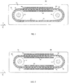
FIG. 1 is a cross-sectional view of an embodiment of a linear motor having an elongated armature and a magnetic assembly including a plurality of magnets arrayed in a loop configuration; -
FIG. 2 is a cross-sectional view of an embodiment of a linear motor having a plurality of elongated armatures and a magnetic assembly including a plurality of magnets arrayed in a loop configuration; -
FIG. 3 depicts aspects of the linear motor ofFIGS. 1 and 2 and illustrates relative orientations of the magnetic assembly and windings disposed on the armature; -
FIG. 4 depicts an embodiment of an actuator assembly including a linear motor; and -
FIG. 5 is a flow chart illustrating an embodiment of a method of operating a linear motor. - A detailed description of one or more embodiments of the disclosed apparatus and method are presented herein by way of exemplification and not limitation with reference to the Figures.
- Embodiments described herein include aspects of a linear motor and methods of operating a linear motor. In one embodiment, a linear motor includes a magnetic assembly arrayed in a loop configuration and configured to extend through a plurality of windings disposed on a linearly extending armature. A linear section of the magnetic assembly extends linearly through the plurality of windings in a direction at least substantially parallel to a longitudinal axis of the armature. Movement of the magnetic assembly through the armature may be transferred to a rotational component of a support structure, which can be used as an actuator to move an aircraft component or other moveable component or device. In one embodiment, the magnetic assembly includes a plurality of magnets having an orientation or polarity in a direction of movement of the magnetic assembly.
- Embodiments described herein also include an actuator assembly including the linear motor, and methods of operating the linear motor and/or the actuator assembly to control movement (e.g., rotation) of a moveable component.
- Referring to
FIG. 1 , an embodiment of alinear motor 100 includes ahousing 101 and amotor assembly 102. Themotor assembly 102 includes amagnetic assembly 104 and anarmature 106. Relative movement between themagnetic assembly 104 and thearmature 106 is generated by interaction between a magnetic field generated by themagnetic assembly 104 and current flowing through windings on thearmature 106. In the embodiment ofFIG. 1 , thearmature 106 is a stationary component (stator) and themagnetic assembly 104 is moveable in response to applying current thereto. Alternatively, themagnetic assembly 104 can be configured as the stationary component and the armature can be configured as the moveable component. - The
armature 106 supports a plurality ofconductor windings 108. In one embodiment, the conductor windings are multi-phase windings. For example, as shown inFIG. 1 , thewindings 108 are three-phase windings having phases U, V and W. Thewindings 108 are wound in a circumferential path around a linearly extending section of themagnetic assembly 104. The linearly extending section of themagnetic assembly 104 in this embodiment is in a direction denoted by an x-axis. In one embodiment, the circumferential path of the windings has a directional component that is in a plane orthogonal to the direction of the linearly extending section, e.g., the x-axis. For example, if the plane is described in polar coordinates defined by a radial coordinate that is perpendicular to the x-axis and an angular coordinate, the circumferential path may be in a direction of the angular coordinate (i.e., an angular direction) or at least a directional component of the path is in a direction of the angular coordinate. - In one embodiment, the
armature 106 is an elongated and linearly extending component having a longitudinal axis that is at least substantially parallel to the x-axis. For example, as shown inFIG. 1 , the armature can be a tubular component (e.g., a hollow rod or shaft) that surrounds at least a linearly extending section of themagnetic assembly 104. Any other armature configuration can be used that supports the windings so that themagnetic assembly 104 can travel through thewindings 108. - In one embodiment, the
magnetic assembly 104 includes a plurality ofmagnets 110 arrayed in a loop configuration. The loop is configured so that themagnets 110 travel through thewindings 108 in the x-axis direction when themagnets 110 are at the linear section of the loop. It is noted that the magnetic assembly can be moved in either direction along the x-axis (e.g., forward or reverse). - The plurality of
magnets 110 may be connected as individual segments each having one or more magnet pitches, which are attached or formed as a chain, attached to a belt or connected to any other suitable structure that allows for linear and rotational movement, such as an automotive style chain or drive belt. For example, themagnets 110 can be attached to abelt 112 that is wrapped around a suitable support structure having rotatingcomponents 114. One or morerotating components 114 or other structures can be operable connected to a gear assembly, shaft or other mechanism for transferring movement and torque generated by themagnetic assembly 104. - In one embodiment, the
linear motor 100 includes multiple armatures that can include windings. For example, as shown inFIG. 2 , thelinear motor 100 can have anadditional armature 116 having a longitudinal axis that is at least substantially parallel to the x-axis and disposed at another location around themagnetic assembly 104. - The
linear motor 100 may include and/or be coupled to one or more additional devices and/or components for operating thelinear motor 100 or controlling aspects of thelinear motor 100. For example, thelinear motor 100 can include a commutator (e.g., including brushes for a brushed DC motor or an inverter/switch or other electronic commutator for a brushless motor). Thelinear motor 100 may include and/or be coupled to a control device or system, such as a feedback device. The feedback device may include components such as resolvers, linear variable differential transformers (LVDTs), encoders and others. -
FIG. 3 shows an embodiment of themagnetic assembly 104 and thewindings 108 and illustrates the relative orientations ofmagnets 110 when they are positioned within thewindings 108. In this embodiment, the polarity of eachmagnet 108 is in the direction of travel of eachmagnet 108. Thewindings 108, which are three-phase windings in this embodiment, are circumferentially oriented around the x-axis. This orientation and the circumferential stator ensures that there is no net attractive force on themagnets 108. - The
linear motor 100 provides for a flat linear stator configuration and stator length that is mathematically infinite and has an infinite stroke. Thelinear motor 100 can thus be a relatively flat motor that can be used for purposes such as force amplification, e.g., by coupling thelinear motor 100 to a gear assembly. - In one embodiment, the
linear motor 100 is incorporated into an actuator or control assembly configured to perform various functions. For example, the actuator can be incorporated into a component of an aircraft, such as a flap or a stabilizer. -
FIG. 4 shows an embodiment of anactuator assembly 200 incorporating a linear motor as described herein. Theactuator assembly 200 includes thelinear motor 100, which is connected to agear assembly 202 via aninput shaft 204. Thelinear motor 100 and thegear assembly 202 may be separate components as shown, or may be incorporated into a single housing or device. Thegear assembly 202 is in turn connected to an aircraft component (not shown), such as a wing flap or aileron, by a drive shaft orcoupler 206. A processor or controller 208 (e.g., part of an aircraft control system) is electrically connected to thelinear motor 100 to control movement of the aircraft component. Although theactuator assembly 200 is described in conjunction with an aircraft component, it is not so limited and can be applied to any device or system that utilizes rotary motors. -
FIG. 5 illustrates amethod 300 of operating a linear motor and/or actuating a moveable component. Themethod 300 is discussed in conjunction with thelinear motor 100 and theactuator assembly 200, although themethod 300 may be utilized in conjunction with any suitable device or system that can utilize a linear motor as described herein. Themethod 300 includes one or more stages 301-304. In one embodiment, themethod 300 includes the execution of all of stages 301-304 in the order described. However, certain stages may be omitted, stages may be added, or the order of the stages changed. - In the
first stage 301, thelinear motor 100 or other electric motor having a linear extending magnetic assembly as described herein is assembled and installed as part of an actuator device, e.g., theactuator assembly 200. For example, the actuator assembly is installed as part of an aircraft control system and is controlled by a pilot, operator and/or processing device (e.g., aircraft computer). - In the
second stage 302, electric current is applied to thewindings 108, e.g., three-phase windings. The electric current flows circumferentially through thewindings 108 around a linear section of themagnetic assembly 104, causing movement ofmagnets 110 in a direction of the x-axis. In thethird stage 303, linear motion and linear force generated by the interaction between thewindings 108 and themagnets 110 is translated to rotational motion and torque via the loop configuration of themagnets 110. In thefourth stage 304, the torque is transferred to a component, e.g., an aileron or other moveable component of an aircraft. Other examples of the component include any moveable component or load (e.g., a pump). - Embodiments described herein provide a number of advantages and technical effects. For example, the linear motor configuration provides a compact design that can fit into thin or small enclosures, and thus allows the motor to be used in circumstances where space is limited. In addition, the linear motor configuration is advantageous for applications where rotary actuation is desired. For example, although conventional linear motor topographies can be used in limited space applications, the stroke of such a motor is limited by the length of the magnet track or forcer rod, and thus may be unsuitable for applications where force amplification is needed through mechanical advantage (i.e., gearing). Embodiments described herein provide an effective and compact mechanism for such applications.
- The term "about" is intended to include the degree of error associated with measurement of the particular quantity based upon the equipment available at the time of filing the application.
- The terminology used herein is for the purpose of describing particular embodiments only and is not intended to be limiting of the present disclosure. As used herein, the singular forms "a", "an" and "the" are intended to include the plural forms as well, unless the context clearly indicates otherwise. It will be further understood that the terms "comprises" and/or "comprising," when used in this specification, specify the presence of stated features, integers, steps, operations, elements, and/or components, but do not preclude the presence or addition of one or more other features, integers, steps, operations, element components, and/or groups thereof.
- While the present disclosure has been described with reference to an exemplary embodiment or embodiments, it will be understood by those skilled in the art that various changes may be made and equivalents may be substituted for elements thereof without departing from the scope of the present invention as claimed. In addition, many modifications may be made to adapt a particular situation or material to the teachings of the present disclosure without departing from the scope thereof as defined by the claims. Therefore, it is intended that the present disclosure not be limited to the particular embodiment disclosed as the best mode contemplated for carrying out this present disclosure, but that the present disclosure will include all embodiments falling within the scope of the claims.
Claims (15)
- A linear motor assembly comprising:an armature (106) extending linearly along an axis, the armature having a plurality of windings (108); anda magnetic assembly (104) including a plurality of magnets (110) arrayed in a loop configuration, a linear section of the plurality of magnets extending linearly through the plurality of windings in a direction parallel to the axis, each magnet of the linear section being oriented in the direction and configured to move in the direction due to interaction between the plurality of windings and a magnetic field generated by the magnetic assembly.
- The linear motor assembly of claim 1, wherein the windings are wound circumferentially around the linear section of the plurality of magnets in a direction having a directional component that is in an angular direction around the linear section.
- The linear motor assembly of claim 1 or 2, wherein the armature is a stationary component.
- The linear motor assembly of claim 1, 2 or 3, wherein the armature is an elongated rigid component.
- The linear motor assembly of claim 4, wherein the armature forms a tube through which the linear section of the plurality of magnets extends.
- The linear motor assembly of any preceding claim, wherein the plurality of magnets are configured as a chain of magnetic components, each of the magnetic components having a polarity in a direction of movement of the chain of magnetic components.
- The linear motor assembly of claim 6, wherein the magnetic components are disposed on at least one of a belt (112) or a chain.
- The linear motor assembly of any preceding claim, further comprising a support structure (114) configured to support the plurality of magnets, wherein movement of the plurality of magnets is configured to rotate at least one component of the support structure.
- The linear motor assembly of claim 8, wherein the at least one component of the support structure is configured to transfer torque to a moveable component.
- The linear motor assembly of claim 9, wherein the at least one component of the support structure is connected between the at least one component of the support structure and the moveable component.
- A method of operating a linear motor assembly, the method comprising:applying an electric current to a plurality of windings, the plurality of windings disposed on an armature extending linearly along an axis; andcausing movement of a magnetic assembly due to interaction between the plurality of windings and a magnetic field generated by a magnetic assembly, the magnetic assembly including a plurality of magnets arrayed in a loop configuration, a linear section of the plurality of magnets extending linearly through the plurality of windings in a direction parallel to the axis, each magnet of the linear section being oriented in the direction, wherein the movement of the magnetic assembly includes a movement of each magnet of the linear section in the direction and through the plurality of windings.
- The method of claim 11, wherein the windings are wound circumferentially around the linear section of the plurality of magnets in a direction having a directional component that is in an angular direction around the linear section.
- The method of claim 11 or 12, wherein the armature is a stationary component.
- The method of claim 11, 12 or 13, wherein the armature is an elongated rigid component.
- The method of claim 14, wherein the armature forms a tube through which the linear section of the plurality of magnets extends.
Applications Claiming Priority (1)
| Application Number | Priority Date | Filing Date | Title |
|---|---|---|---|
| US15/690,605 US11075571B2 (en) | 2017-08-30 | 2017-08-30 | Infinite stroke linear motor |
Publications (1)
| Publication Number | Publication Date |
|---|---|
| EP3451515A1 true EP3451515A1 (en) | 2019-03-06 |
Family
ID=63442522
Family Applications (1)
| Application Number | Title | Priority Date | Filing Date |
|---|---|---|---|
| EP18191262.7A Ceased EP3451515A1 (en) | 2017-08-30 | 2018-08-28 | Infinite stroke linear motor |
Country Status (2)
| Country | Link |
|---|---|
| US (1) | US11075571B2 (en) |
| EP (1) | EP3451515A1 (en) |
Citations (6)
| Publication number | Priority date | Publication date | Assignee | Title |
|---|---|---|---|---|
| US1132445A (en) * | 1913-07-02 | 1915-03-16 | John B Conrad | Electric motor. |
| US4803387A (en) * | 1987-06-29 | 1989-02-07 | Fmc Corporation | Electric drive motor |
| JP2004096913A (en) * | 2002-08-30 | 2004-03-25 | Sumitomo Electric Ind Ltd | motor |
| US20090284192A1 (en) * | 2007-05-15 | 2009-11-19 | Deal Clarence D | Electric motor with a permanent magnet carrier rotating a sprocket |
| EP3199807A1 (en) * | 2016-01-28 | 2017-08-02 | The Boeing Company | Solid-state motor and associated systems and methods |
| EP3451514A1 (en) * | 2017-08-28 | 2019-03-06 | Hamilton Sundstrand Corporation | Actuator assembly |
Family Cites Families (9)
| Publication number | Priority date | Publication date | Assignee | Title |
|---|---|---|---|---|
| US4514602A (en) * | 1982-12-27 | 1985-04-30 | Owen D W | Switching apparatus |
| US5001357A (en) * | 1989-03-29 | 1991-03-19 | Adams Nelson P | Linear gravitational generator |
| US5913091A (en) * | 1996-05-21 | 1999-06-15 | Minolta Co., Ltd. | Image reading apparatus |
| JP3395155B2 (en) | 1999-05-07 | 2003-04-07 | 株式会社日立製作所 | Linear motor and manufacturing method thereof |
| JP4387181B2 (en) | 2003-01-22 | 2009-12-16 | Thk株式会社 | Linear motor and linear guide device |
| JP4259978B2 (en) | 2003-03-25 | 2009-04-30 | Thk株式会社 | Linear motor actuator |
| US7675202B1 (en) | 2007-07-18 | 2010-03-09 | Benjamin Huang | Isotropic ring magnet linear voice coil motor |
| US7786684B2 (en) * | 2007-10-22 | 2010-08-31 | Honeywell International Inc. | Electromechanical flight control system and method for rotorcraft |
| SG174078A1 (en) | 2008-05-28 | 2011-09-29 | Vetco Gray Inc | Subsea electric actuator using linear motor |
-
2017
- 2017-08-30 US US15/690,605 patent/US11075571B2/en not_active Expired - Fee Related
-
2018
- 2018-08-28 EP EP18191262.7A patent/EP3451515A1/en not_active Ceased
Patent Citations (6)
| Publication number | Priority date | Publication date | Assignee | Title |
|---|---|---|---|---|
| US1132445A (en) * | 1913-07-02 | 1915-03-16 | John B Conrad | Electric motor. |
| US4803387A (en) * | 1987-06-29 | 1989-02-07 | Fmc Corporation | Electric drive motor |
| JP2004096913A (en) * | 2002-08-30 | 2004-03-25 | Sumitomo Electric Ind Ltd | motor |
| US20090284192A1 (en) * | 2007-05-15 | 2009-11-19 | Deal Clarence D | Electric motor with a permanent magnet carrier rotating a sprocket |
| EP3199807A1 (en) * | 2016-01-28 | 2017-08-02 | The Boeing Company | Solid-state motor and associated systems and methods |
| EP3451514A1 (en) * | 2017-08-28 | 2019-03-06 | Hamilton Sundstrand Corporation | Actuator assembly |
Also Published As
| Publication number | Publication date |
|---|---|
| US20190068040A1 (en) | 2019-02-28 |
| US11075571B2 (en) | 2021-07-27 |
Similar Documents
| Publication | Publication Date | Title |
|---|---|---|
| JP7019907B2 (en) | Improved grain size encoder-less motor and usage | |
| US11677296B2 (en) | High force rotary actuator | |
| EP1927180B1 (en) | Ironless magnetic linear motors having levitating and transversal force capacities | |
| US20020105241A1 (en) | Integrated magnetic bearing | |
| JP7472207B2 (en) | Eddy Current Repulsion Motor | |
| US10177641B2 (en) | Stator assembly including stator elements with slotted stator cores for use in an electrical motor | |
| US7994672B2 (en) | Limited angle external rotor motor actuator system | |
| JP2018130009A (en) | Three degree-of-freedom electromagnetic machine controlling system and method | |
| US8427015B2 (en) | Multihead-type coreless linear motor | |
| Tanaka et al. | Development of a cross-coupled 2DOF direct drive motor | |
| EP2412086B1 (en) | Motor for linear and rotary movement | |
| JP5150123B2 (en) | Direct acting electric actuator for vibration control | |
| US11075571B2 (en) | Infinite stroke linear motor | |
| WO2018148850A1 (en) | Methods and apparatus for linear electric machine | |
| JP2016025700A (en) | Magnetic screw actuator | |
| CN107925336B (en) | Transverse flux linear motor | |
| CN113991935A (en) | Hybrid spherical electric motor, system and aircraft comprising same | |
| KR100953385B1 (en) | Rigidity generator using combined application of permanent magnet and electromagnet and joint of robot manipulator | |
| EP3666643B1 (en) | Propeller system | |
| US8061230B2 (en) | Arrangement for the control of a gear box | |
| CN218449828U (en) | Steering power device and vehicle with same | |
| JP2001292591A (en) | Linear motor driving apparatus and method | |
| TR2025004413A2 (en) | HELICAL MOVEMENT, DOUBLE-AXIS, PERMANENT MAGNET BRUSHLESS DC MOTOR | |
| CN109286301A (en) | Linear motor and automation equipment | |
| JPH07337048A (en) | Composite motor |
Legal Events
| Date | Code | Title | Description |
|---|---|---|---|
| PUAI | Public reference made under article 153(3) epc to a published international application that has entered the european phase |
Free format text: ORIGINAL CODE: 0009012 |
|
| STAA | Information on the status of an ep patent application or granted ep patent |
Free format text: STATUS: THE APPLICATION HAS BEEN PUBLISHED |
|
| AK | Designated contracting states |
Kind code of ref document: A1 Designated state(s): AL AT BE BG CH CY CZ DE DK EE ES FI FR GB GR HR HU IE IS IT LI LT LU LV MC MK MT NL NO PL PT RO RS SE SI SK SM TR |
|
| AX | Request for extension of the european patent |
Extension state: BA ME |
|
| STAA | Information on the status of an ep patent application or granted ep patent |
Free format text: STATUS: REQUEST FOR EXAMINATION WAS MADE |
|
| 17P | Request for examination filed |
Effective date: 20190830 |
|
| RBV | Designated contracting states (corrected) |
Designated state(s): AL AT BE BG CH CY CZ DE DK EE ES FI FR GB GR HR HU IE IS IT LI LT LU LV MC MK MT NL NO PL PT RO RS SE SI SK SM TR |
|
| STAA | Information on the status of an ep patent application or granted ep patent |
Free format text: STATUS: EXAMINATION IS IN PROGRESS |
|
| 17Q | First examination report despatched |
Effective date: 20210311 |
|
| STAA | Information on the status of an ep patent application or granted ep patent |
Free format text: STATUS: THE APPLICATION HAS BEEN REFUSED |
|
| 18R | Application refused |
Effective date: 20221213 |