EP3451472A1 - Surge protection element - Google Patents
Surge protection element Download PDFInfo
- Publication number
- EP3451472A1 EP3451472A1 EP17789121.5A EP17789121A EP3451472A1 EP 3451472 A1 EP3451472 A1 EP 3451472A1 EP 17789121 A EP17789121 A EP 17789121A EP 3451472 A1 EP3451472 A1 EP 3451472A1
- Authority
- EP
- European Patent Office
- Prior art keywords
- insulating tube
- projecting
- protective device
- surge protective
- pair
- Prior art date
- Legal status (The legal status is an assumption and is not a legal conclusion. Google has not performed a legal analysis and makes no representation as to the accuracy of the status listed.)
- Withdrawn
Links
- 230000001681 protective effect Effects 0.000 claims abstract description 36
- 238000007789 sealing Methods 0.000 claims abstract description 21
- 229910052751 metal Inorganic materials 0.000 description 24
- 239000002184 metal Substances 0.000 description 24
- 238000010891 electric arc Methods 0.000 description 9
- 230000015572 biosynthetic process Effects 0.000 description 8
- 239000000463 material Substances 0.000 description 7
- 239000007789 gas Substances 0.000 description 4
- 238000004891 communication Methods 0.000 description 3
- 239000002243 precursor Substances 0.000 description 3
- 239000004115 Sodium Silicate Substances 0.000 description 2
- 230000002159 abnormal effect Effects 0.000 description 2
- 238000005219 brazing Methods 0.000 description 2
- FJDQFPXHSGXQBY-UHFFFAOYSA-L caesium carbonate Chemical compound [Cs+].[Cs+].[O-]C([O-])=O FJDQFPXHSGXQBY-UHFFFAOYSA-L 0.000 description 2
- 229910000024 caesium carbonate Inorganic materials 0.000 description 2
- 230000000694 effects Effects 0.000 description 2
- 238000005516 engineering process Methods 0.000 description 2
- 230000004927 fusion Effects 0.000 description 2
- 239000011521 glass Substances 0.000 description 2
- 238000010438 heat treatment Methods 0.000 description 2
- 238000009434 installation Methods 0.000 description 2
- 238000005245 sintering Methods 0.000 description 2
- NTHWMYGWWRZVTN-UHFFFAOYSA-N sodium silicate Chemical compound [Na+].[Na+].[O-][Si]([O-])=O NTHWMYGWWRZVTN-UHFFFAOYSA-N 0.000 description 2
- 229910052911 sodium silicate Inorganic materials 0.000 description 2
- 229910017944 Ag—Cu Inorganic materials 0.000 description 1
- 229910018503 SF6 Inorganic materials 0.000 description 1
- 239000000956 alloy Substances 0.000 description 1
- 229910045601 alloy Inorganic materials 0.000 description 1
- PNEYBMLMFCGWSK-UHFFFAOYSA-N aluminium oxide Inorganic materials [O-2].[O-2].[O-2].[Al+3].[Al+3] PNEYBMLMFCGWSK-UHFFFAOYSA-N 0.000 description 1
- 229910052786 argon Inorganic materials 0.000 description 1
- 229910052792 caesium Inorganic materials 0.000 description 1
- 229910052799 carbon Inorganic materials 0.000 description 1
- 229910002092 carbon dioxide Inorganic materials 0.000 description 1
- 239000003575 carbonaceous material Substances 0.000 description 1
- 238000009125 cardiac resynchronization therapy Methods 0.000 description 1
- 239000000919 ceramic Substances 0.000 description 1
- 239000004020 conductor Substances 0.000 description 1
- 239000011222 crystalline ceramic Substances 0.000 description 1
- 229910002106 crystalline ceramic Inorganic materials 0.000 description 1
- 229910052734 helium Inorganic materials 0.000 description 1
- 239000011261 inert gas Substances 0.000 description 1
- 238000009413 insulation Methods 0.000 description 1
- 229910052743 krypton Inorganic materials 0.000 description 1
- 239000005355 lead glass Substances 0.000 description 1
- 239000004973 liquid crystal related substance Substances 0.000 description 1
- 239000000155 melt Substances 0.000 description 1
- 229910052754 neon Inorganic materials 0.000 description 1
- 239000000843 powder Substances 0.000 description 1
- 238000010248 power generation Methods 0.000 description 1
- 229910052708 sodium Inorganic materials 0.000 description 1
- 239000011734 sodium Substances 0.000 description 1
- 230000003685 thermal hair damage Effects 0.000 description 1
- 229910052724 xenon Inorganic materials 0.000 description 1
Images

Classifications
-
- H—ELECTRICITY
- H01—ELECTRIC ELEMENTS
- H01T—SPARK GAPS; OVERVOLTAGE ARRESTERS USING SPARK GAPS; SPARKING PLUGS; CORONA DEVICES; GENERATING IONS TO BE INTRODUCED INTO NON-ENCLOSED GASES
- H01T4/00—Overvoltage arresters using spark gaps
- H01T4/10—Overvoltage arresters using spark gaps having a single gap or a plurality of gaps in parallel
- H01T4/12—Overvoltage arresters using spark gaps having a single gap or a plurality of gaps in parallel hermetically sealed
-
- H—ELECTRICITY
- H01—ELECTRIC ELEMENTS
- H01T—SPARK GAPS; OVERVOLTAGE ARRESTERS USING SPARK GAPS; SPARKING PLUGS; CORONA DEVICES; GENERATING IONS TO BE INTRODUCED INTO NON-ENCLOSED GASES
- H01T1/00—Details of spark gaps
- H01T1/02—Means for extinguishing arc
-
- H—ELECTRICITY
- H01—ELECTRIC ELEMENTS
- H01T—SPARK GAPS; OVERVOLTAGE ARRESTERS USING SPARK GAPS; SPARKING PLUGS; CORONA DEVICES; GENERATING IONS TO BE INTRODUCED INTO NON-ENCLOSED GASES
- H01T1/00—Details of spark gaps
- H01T1/20—Means for starting arc or facilitating ignition of spark gap
-
- H—ELECTRICITY
- H01—ELECTRIC ELEMENTS
- H01T—SPARK GAPS; OVERVOLTAGE ARRESTERS USING SPARK GAPS; SPARKING PLUGS; CORONA DEVICES; GENERATING IONS TO BE INTRODUCED INTO NON-ENCLOSED GASES
- H01T1/00—Details of spark gaps
- H01T1/20—Means for starting arc or facilitating ignition of spark gap
- H01T1/22—Means for starting arc or facilitating ignition of spark gap by the shape or the composition of the electrodes
-
- H—ELECTRICITY
- H02—GENERATION; CONVERSION OR DISTRIBUTION OF ELECTRIC POWER
- H02H—EMERGENCY PROTECTIVE CIRCUIT ARRANGEMENTS
- H02H9/00—Emergency protective circuit arrangements for limiting excess current or voltage without disconnection
- H02H9/04—Emergency protective circuit arrangements for limiting excess current or voltage without disconnection responsive to excess voltage
- H02H9/06—Emergency protective circuit arrangements for limiting excess current or voltage without disconnection responsive to excess voltage using spark-gap arresters
Definitions
- the present invention relates to a surge protective device for protecting a wide variety of equipment from surges caused by a lightning strike or the like so as to prevent accidents.
- the connecting parts of telephones, facsimile machines, and electronic devices for communication equipment such as a modem to communication lines, and power lines, antenna, as well as image display driving circuits for CRTs, liquid crystal display TVs, plasma display TVs, and the like are vulnerable to electric shocks such as abnormal voltage (surge voltage) due to a lightning surge or electrostatic surge.
- surge protective devices in order to prevent electronic devices and the printed circuit boards equipped therewith from being broken down due to thermal damage, ignition, or the like caused by abnormal voltage.
- Patent documents 1 and 2 disclose an arrester (surge protective device) which includes an insulating tube being a cylindrical body made of ceramic, glass, or the like, and a pair of convex electrode portions projecting from a pair of sealing electrodes for sealing the insulating tube so as to face to each other.
- a metal constituting the convex electrode portions can be melt and scattered by an arc discharge and then the metal component can adhere to the inner surface of the insulating tube, which may deteriorate the insulation between the pair of sealing electrodes.
- a surge application current is greater than 10 kA
- a metal can scatter remarkably.
- an energization circuit may be formed on the inner circumferential surface of the insulating tube, thereby causing a short circuit. In such a case, this surge protective device may be mistakenly considered to end its operating life.
- the present invention has been made in view of the aforementioned circumstances, and an object of the present invention is to provide a surge protective device that can suppress the occurrence of a short circuit due to the adhesion of a metal component scattered by an arc discharge.
- a surge protective device comprises: an insulating tube and a pair of sealing electrodes for closing openings on both ends of the insulating tube so as to seal a discharge control gas inside the tube; wherein the pair of sealing electrodes has a pair of convex electrode portions projecting inwardly so as to face to each other, and at least one projecting part projecting inwardly in a radial direction and extending in a circumferential direction is formed on the inner circumferential surface of the insulating tube.
- this surge protective device since at least one projecting part projecting inwardly in a radial direction and extending in a circumferential direction is formed on the inner circumferential surface of the insulating tube, a metal component scattered by an arc discharge is hard to adhere to the region shaded by the projecting part. Hence, an energization circuit is hard to be formed due to the adhered metal, and thus the occurrence of a short circuit can be suppressed.
- the projecting part can lengthen the creepage distance between the sealing electrodes through the inner circumferential surface of the insulating tube, and this can also preclude the formation of an energization circuit due to the adhered metal.
- a surge protective device is characterized by the surge protective device according to the first aspect, wherein a plurality of the projecting parts are formed in the axial direction of the insulating tube.
- this surge protective device since the plurality of projecting parts are formed in the axial direction of the insulating tube, the formation of an energization circuit due to the adhered metal can be suppressed by the plurality of projecting parts, which can further prevent the occurrence of a short circuit.
- a surge protective device is characterized by the surge protective device according to the first or second aspect, wherein the projecting part is formed at least in the vicinity of one of the openings of the insulating tube.
- the projecting part is formed at least in the vicinity of one of the openings of the insulating tube, the projecting part can be located in the vicinity of one of the openings to which a metal component due to arc discharge is harder to adhere than to the central region. Therefore, the occurrence of a short circuit between the pair of sealing electrodes can be effectively prevented.
- a surge protective device is characterized by the surge protective device according to any one of the first to third aspects, wherein a groove part extending in a circumferential direction is formed on the inner circumferential surface of the insulating tube, and the groove part is arranged in proximity to the outward surface of the projecting part.
- the groove part is arranged in proximity to the outward surface of the projecting part, the groove part is shaded by the projecting part. Hence, a metal component is hard to enter the groove part, and thus the formation of an energization circuit can be further suppressed.
- both of the projecting part and the groove part can further lengthen the creepage distance between the sealing electrodes through the inner circumferential surface of the insulating tube, an energization circuit can be hard to be formed.
- the surge protective device of the present invention since at least one projecting part projecting inwardly in a radial direction and extending in a circumferential direction is formed on the inner circumferential surface of the insulating tube, even when a metal component scattered by an arc discharge adheres to the inner circumferential surface of the insulating tube, it is hard to adhere to the region shaded by the projecting part. Hence, an energization circuit is hard to be formed due to the adhered metal, and thus the occurrence of a short circuit can be suppressed.
- the surge protective device of the present invention can achieve a long operating life, and the number of surge application by which the element can operate can be increased.
- the surge protective device of the present invention is suitable for the power source and communication equipment for infrastructure (railroad-related or regenerated energy-related (e.g., solar cell, wind power generation, and the like)) where the tolerance to a large current surge is required.
- FIGs. 1 and 2 a surge protective device according to a first embodiment of the present invention will be described with reference to FIGs. 1 and 2 .
- the scale of each component may be changed as appropriate so that each component is recognizable or is readily recognized.
- a surge protective device 1 includes an insulating tube 2 and a pair of sealing electrodes 3 for closing the openings on both ends of the insulating tube 2 so as to seal a discharge control gas inside the tube.
- the surge protective device 1 also includes a discharge-assisting part 4 made of an ion-source material on the inner circumferential surface of an insulating tube 2.
- the pair of sealing electrodes 3 has a pair of convex electrode portions 5 projecting inwardly so as to face to each other.
- a pair of the projecting parts 2a is provided at intervals from each other in the direction of an axis C of the insulating tube 2 in the vicinity of the openings on both ends of the insulating tube 2.
- the projecting parts 2a are annularly formed in a circumferential direction around the axis C.
- the projecting parts 2a are set to have a projection amount h so as not to make contact with the convex electrode portions 5 opposing thereto.
- the projection amount h and a width t1 of the projecting parts 2a are set depending on the installation position of the projecting parts 2a or the like.
- projecting parts 2a are fabricated by forming a plurality of annular projecting parts on the inner circumferential surface of the insulating tube 2 when the insulating tube 2 is fabricated, for example when the insulating tube 2 is molded but before it is sintered, and then by sintering them. They can also be fabricated by prefabricating projecting parts having a ring or arc shape and then inserting them into grooves formed on the inner circumferential surface of the insulating tube 2.
- discharge active layers 8 On the opposing surfaces of the convex electrode portions 5 are formed discharge active layers 8 with a material having higher electron emission characteristics than that of the sealing electrodes 3.
- the discharge active layers 8 include, for example, Si and O as the main component elements together with at least one of Na, Cs, and C. These discharge active layers 8 are fabricated by adding a cesium carbonate powder to a sodium silicate solution to form a precursor, applying the precursor on the opposing surfaces of the pair of convex electrode portions 5, and then subjecting the applied precursor to a heat treatment at a temperature or higher at which sodium silicate softens and at a temperature or higher cesium carbonate melts and decomposes.
- the discharge-assisting part 4 is made of a conductive material such as, for example, a carbon material.
- the discharge-assisting part 4 is formed into a straight or dashed line shape along the axis C. This discharge-assisting part 4 is formed between the pair of projecting parts 2a.
- a plurality of the discharge-assisting parts 4 may be formed at intervals from each other in a circumferential direction.
- the sealing electrodes 3 are composed of, for example, 42-alloy (Fe: 58 wt%, Ni: 42 wt%), Cu, or the like.
- Each of the sealing electrodes 3 has a discoidal flange 7 fixed to each of the openings on both ends of the insulating tube 2 with a conductive fusion material (not shown) in a close contact state by a heat treatment.
- a conductive fusion material (not shown) in a close contact state by a heat treatment.
- the convex electrode portion 5 having a columnar shape is integrally formed with the flange 7, which projects inwardly and has a smaller outer diameter than the inner diameter of the insulating tube 2.
- the insulating tube 2 is made of a crystalline ceramic material such as alumina.
- the insulating tube 2 may be a tube made of a glass such as a lead glass.
- the conductive fusion material described above is a brazing material containing Ag, e.g., an Ag-Cu brazing material.
- the discharge control gas sealed inside the insulating tube 2 as described above is an inert gas or the like such as, for example, He, Ar, Ne, Xe, Kr, SF 6 , CO 2 , C 3 F 8 , C 2 F 6 , CF 4 , H 2 , air, etc., or a combination of these gases.
- an inert gas or the like such as, for example, He, Ar, Ne, Xe, Kr, SF 6 , CO 2 , C 3 F 8 , C 2 F 6 , CF 4 , H 2 , air, etc., or a combination of these gases.
- the surge protective device 1 When an overvoltage or overcurrent enters the surge protective device 1, firstly the initial discharge occurs between the discharge-assisting part 4 and the convex electrode portions 5, which triggers further progress of discharge, and then an arc discharge occurs from one of the convex electrode portions 5 to the other of the convex electrode portions 5.
- the surge protective device 1 since at least one projecting part 2a projecting inwardly in a radial direction and extending in a circumferential direction is formed on the inner circumferential surface of the insulating tube 2, a metal component scattered by an arc discharge is hard to adhere to the region shaded by the projecting part 2a. Hence, an energization circuit is hard to be formed due to the adhered metal, and thus the occurrence of a short circuit can be suppressed.
- the projecting part 2a can lengthen the creepage distance between the sealing electrodes 3 through the inner circumferential surface of the insulating tube 2, and this can also preclude the formation of an energization circuit due to the adhered metal.
- the plurality of projecting parts 2a are formed in the axial direction of the insulating tube 2, the formation of an energization circuit due to the adhered metal can be suppressed by the plurality of projecting parts 2a, which can further prevent the occurrence of a short circuit.
- the projecting parts 2a are formed at least in the vicinity of the openings of the insulating tube 2, the projecting parts 2a can be located in the vicinity of the openings to which a metal component due to arc discharge is harder to adhere than to the central region. Hence, the occurrence of a short circuit between the pair of sealing electrodes 3 can be effectively prevented.
- FIGs. 3 and 4 a surge protective device according to a second embodiment of the present invention will be described below with reference to FIGs. 3 and 4 .
- the same components as those in the first embodiment described above are denoted by the same reference numerals, and thus the description thereof is omitted.
- the second embodiment is different from the first embodiment in the following points.
- the first embodiment only the projecting parts 2a are formed on the inner circumferential surface of the insulating tube 2
- a surge protective device 21 according to the second embodiment as shown in FIGs. 3 and 4 , not only the projecting parts 2a but also groove parts 22b are formed on the inner circumferential surface of the insulating tube 22.
- the groove parts 22b extending in a circumferential direction are formed on the inner circumferential surface of the insulating tube 22, and the groove parts 22b are arranged in proximity to the outward surface of the projecting parts 2a.
- the groove parts 22b are provided adjacent to not the surface facing inwardly but the surface facing outwardly (i.e., the surface closer to the pair of openings of the insulating tube 22) of both surfaces of the projecting part 2a.
- Each of the groove parts 22b is formed by making a slit in the inner circumferential surface of the insulating tube 22 in a vertical direction relative thereto so as to have a rectangular shape. Note that the larger a depth L of the groove part 22b is, the more the formation of an energization circuit due to the adhesion of a metal component inside the groove part 22b can be suppressed. In addition, a width t2 of the groove part 22b is set depending on the projection amount h of the projecting part 2a adjacent thereto, the installation position, or the like.
- each of the groove parts 22b is annularly formed in a circumferential direction around the axis C.
- These groove parts 22b are fabricated by forming a plurality of grooves having a slit-like shape on the inner circumferential surface of the insulating tube 22 when the insulating tube 22 is fabricated, for example when the insulating tube 22 is molded but before it is sintered, and then by sintering them.
- the groove parts 22b are arranged in proximity to the outward surface of the projecting parts 2a, the groove parts 22b can be shaded by the projecting parts 2a. Hence, a metal component can be hard to enter the groove parts 22b, and thus the formation of an energization circuit can be further suppressed.
- both of the projecting parts 2a and the groove parts 22b can lengthen the creepage distance between the sealing electrodes 3 through the inner circumferential surface of the insulating tube 22, an energization circuit can be hard to be formed.
- the projecting parts and the groove parts are annularly formed along the inner circumferential surface of the insulating tube, they may be formed in an arc shape along the inner circumferential surface of the insulating tube.
- the projecting parts described above project with the cross-section thereof being a rectangular shape
- the cross-section may have another shape.
- the projecting part may project with the cross-section thereof being a triangular shape.
Landscapes
- Thermistors And Varistors (AREA)
- Emergency Protection Circuit Devices (AREA)
Abstract
Description
- The present invention relates to a surge protective device for protecting a wide variety of equipment from surges caused by a lightning strike or the like so as to prevent accidents.
- The connecting parts of telephones, facsimile machines, and electronic devices for communication equipment such as a modem to communication lines, and power lines, antenna, as well as image display driving circuits for CRTs, liquid crystal display TVs, plasma display TVs, and the like are vulnerable to electric shocks such as abnormal voltage (surge voltage) due to a lightning surge or electrostatic surge. To these parts are installed surge protective devices in order to prevent electronic devices and the printed circuit boards equipped therewith from being broken down due to thermal damage, ignition, or the like caused by abnormal voltage.
- As conventional technologies,
Patent documents -
- [Patent Document 1] Japanese Utility Model Registration No.
3151069 - [Patent Document 2] Japanese Unexamined Patent Application Publication
H05-36460 - The following problems still remain in the conventional technologies described above.
- Specifically, a metal constituting the convex electrode portions can be melt and scattered by an arc discharge and then the metal component can adhere to the inner surface of the insulating tube, which may deteriorate the insulation between the pair of sealing electrodes. In particular, when a surge application current is greater than 10 kA, a metal can scatter remarkably. And then, when a large amount of metal component adheres to the inner surface of the insulating tube, an energization circuit may be formed on the inner circumferential surface of the insulating tube, thereby causing a short circuit. In such a case, this surge protective device may be mistakenly considered to end its operating life.
- The present invention has been made in view of the aforementioned circumstances, and an object of the present invention is to provide a surge protective device that can suppress the occurrence of a short circuit due to the adhesion of a metal component scattered by an arc discharge.
- The present invention adopts the following configuration in order to overcome the aforementioned problems. Specifically, a surge protective device according to a first aspect of the present invention, comprises: an insulating tube and a pair of sealing electrodes for closing openings on both ends of the insulating tube so as to seal a discharge control gas inside the tube; wherein the pair of sealing electrodes has a pair of convex electrode portions projecting inwardly so as to face to each other, and at least one projecting part projecting inwardly in a radial direction and extending in a circumferential direction is formed on the inner circumferential surface of the insulating tube.
- Specifically, in this surge protective device, since at least one projecting part projecting inwardly in a radial direction and extending in a circumferential direction is formed on the inner circumferential surface of the insulating tube, a metal component scattered by an arc discharge is hard to adhere to the region shaded by the projecting part. Hence, an energization circuit is hard to be formed due to the adhered metal, and thus the occurrence of a short circuit can be suppressed. In addition, the projecting part can lengthen the creepage distance between the sealing electrodes through the inner circumferential surface of the insulating tube, and this can also preclude the formation of an energization circuit due to the adhered metal.
- A surge protective device according to a second aspect of the present invention is characterized by the surge protective device according to the first aspect, wherein a plurality of the projecting parts are formed in the axial direction of the insulating tube.
- Specifically, in this surge protective device, since the plurality of projecting parts are formed in the axial direction of the insulating tube, the formation of an energization circuit due to the adhered metal can be suppressed by the plurality of projecting parts, which can further prevent the occurrence of a short circuit.
- A surge protective device according to a third aspect of the present invention is characterized by the surge protective device according to the first or second aspect, wherein the projecting part is formed at least in the vicinity of one of the openings of the insulating tube.
- Specifically, in this surge protective device, since the projecting part is formed at least in the vicinity of one of the openings of the insulating tube, the projecting part can be located in the vicinity of one of the openings to which a metal component due to arc discharge is harder to adhere than to the central region. Therefore, the occurrence of a short circuit between the pair of sealing electrodes can be effectively prevented.
- A surge protective device according to a fourth aspect of the present invention is characterized by the surge protective device according to any one of the first to third aspects, wherein a groove part extending in a circumferential direction is formed on the inner circumferential surface of the insulating tube, and the groove part is arranged in proximity to the outward surface of the projecting part.
- Specifically, in this surge protective device, since the groove part is arranged in proximity to the outward surface of the projecting part, the groove part is shaded by the projecting part. Hence, a metal component is hard to enter the groove part, and thus the formation of an energization circuit can be further suppressed. In addition, since both of the projecting part and the groove part can further lengthen the creepage distance between the sealing electrodes through the inner circumferential surface of the insulating tube, an energization circuit can be hard to be formed.
- According to the present invention, the following effects may be provided.
- Specifically, according to the surge protective device of the present invention, since at least one projecting part projecting inwardly in a radial direction and extending in a circumferential direction is formed on the inner circumferential surface of the insulating tube, even when a metal component scattered by an arc discharge adheres to the inner circumferential surface of the insulating tube, it is hard to adhere to the region shaded by the projecting part. Hence, an energization circuit is hard to be formed due to the adhered metal, and thus the occurrence of a short circuit can be suppressed.
- Therefore, the surge protective device of the present invention can achieve a long operating life, and the number of surge application by which the element can operate can be increased. In particular, the surge protective device of the present invention is suitable for the power source and communication equipment for infrastructure (railroad-related or regenerated energy-related (e.g., solar cell, wind power generation, and the like)) where the tolerance to a large current surge is required.
-
-
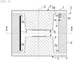
FIG. 1 is an axial cross-sectional view showing a surge protective device according to a first embodiment of the present invention. -
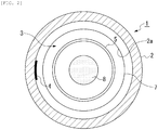
FIG. 2 is a cross-sectional view along line A-A inFIG. 1 . -
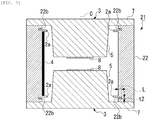
FIG. 3 is an axial cross-sectional view showing a surge protective device according to a second embodiment of the present invention. -
FIG. 4 is an enlarged cross-sectional view showing the essential part of the surge protective device according to the second embodiment. - Hereinafter, a surge protective device according to a first embodiment of the present invention will be described with reference to
FIGs. 1 and2 . In the drawings referenced in the following description, the scale of each component may be changed as appropriate so that each component is recognizable or is readily recognized. - As shown in
FIGs. 1 and2 , a surgeprotective device 1 according to the present embodiment includes aninsulating tube 2 and a pair ofsealing electrodes 3 for closing the openings on both ends of theinsulating tube 2 so as to seal a discharge control gas inside the tube. - The surge
protective device 1 according to the present embodiment also includes a discharge-assistingpart 4 made of an ion-source material on the inner circumferential surface of aninsulating tube 2. - The pair of sealing
electrodes 3 has a pair ofconvex electrode portions 5 projecting inwardly so as to face to each other. - On the inner circumferential surface of the
insulating tube 2 is formed at least one projectingpart 2a projecting inwardly in a radial direction and extending in a circumferential direction. In the present embodiment, a pair of the projectingparts 2a is provided at intervals from each other in the direction of an axis C of theinsulating tube 2 in the vicinity of the openings on both ends of theinsulating tube 2. - The projecting
parts 2a are annularly formed in a circumferential direction around the axis C. In addition, the projectingparts 2a are set to have a projection amount h so as not to make contact with theconvex electrode portions 5 opposing thereto. Note that the projection amount h and a width t1 of the projectingparts 2a are set depending on the installation position of the projectingparts 2a or the like. - These projecting
parts 2a are fabricated by forming a plurality of annular projecting parts on the inner circumferential surface of theinsulating tube 2 when theinsulating tube 2 is fabricated, for example when theinsulating tube 2 is molded but before it is sintered, and then by sintering them. They can also be fabricated by prefabricating projecting parts having a ring or arc shape and then inserting them into grooves formed on the inner circumferential surface of theinsulating tube 2. - Note that the larger the projection amount h of the projecting
parts 2a is, the more the formation of an energization circuit due to the adhesion of a metal component can be suppressed. - On the opposing surfaces of the
convex electrode portions 5 are formed dischargeactive layers 8 with a material having higher electron emission characteristics than that of thesealing electrodes 3. - The discharge
active layers 8 include, for example, Si and O as the main component elements together with at least one of Na, Cs, and C. These dischargeactive layers 8 are fabricated by adding a cesium carbonate powder to a sodium silicate solution to form a precursor, applying the precursor on the opposing surfaces of the pair ofconvex electrode portions 5, and then subjecting the applied precursor to a heat treatment at a temperature or higher at which sodium silicate softens and at a temperature or higher cesium carbonate melts and decomposes. - The discharge-assisting
part 4 is made of a conductive material such as, for example, a carbon material. - In addition, in the present embodiment, the discharge-assisting
part 4 is formed into a straight or dashed line shape along the axis C. This discharge-assistingpart 4 is formed between the pair of projectingparts 2a. - Note that, although one piece of the discharge-assisting
part 4 is shown along the axis C inFIG. 1 , a plurality of the discharge-assistingparts 4 may be formed at intervals from each other in a circumferential direction. - The sealing
electrodes 3 are composed of, for example, 42-alloy (Fe: 58 wt%, Ni: 42 wt%), Cu, or the like. - Each of the sealing
electrodes 3 has adiscoidal flange 7 fixed to each of the openings on both ends of theinsulating tube 2 with a conductive fusion material (not shown) in a close contact state by a heat treatment. Inside theflange 7, theconvex electrode portion 5 having a columnar shape is integrally formed with theflange 7, which projects inwardly and has a smaller outer diameter than the inner diameter of theinsulating tube 2. - The
insulating tube 2 is made of a crystalline ceramic material such as alumina. However, the insulatingtube 2 may be a tube made of a glass such as a lead glass. - The conductive fusion material described above is a brazing material containing Ag, e.g., an Ag-Cu brazing material.
- The discharge control gas sealed inside the insulating
tube 2 as described above is an inert gas or the like such as, for example, He, Ar, Ne, Xe, Kr, SF6, CO2, C3F8, C2F6, CF4, H2, air, etc., or a combination of these gases. - When an overvoltage or overcurrent enters the surge
protective device 1, firstly the initial discharge occurs between the discharge-assistingpart 4 and theconvex electrode portions 5, which triggers further progress of discharge, and then an arc discharge occurs from one of theconvex electrode portions 5 to the other of theconvex electrode portions 5. - As described above, in the surge
protective device 1 according to the present embodiment, since at least one projectingpart 2a projecting inwardly in a radial direction and extending in a circumferential direction is formed on the inner circumferential surface of the insulatingtube 2, a metal component scattered by an arc discharge is hard to adhere to the region shaded by the projectingpart 2a. Hence, an energization circuit is hard to be formed due to the adhered metal, and thus the occurrence of a short circuit can be suppressed. - In addition, the projecting
part 2a can lengthen the creepage distance between the sealingelectrodes 3 through the inner circumferential surface of the insulatingtube 2, and this can also preclude the formation of an energization circuit due to the adhered metal. - In particular, since the plurality of projecting
parts 2a are formed in the axial direction of the insulatingtube 2, the formation of an energization circuit due to the adhered metal can be suppressed by the plurality of projectingparts 2a, which can further prevent the occurrence of a short circuit. - Furthermore, since the projecting
parts 2a are formed at least in the vicinity of the openings of the insulatingtube 2, the projectingparts 2a can be located in the vicinity of the openings to which a metal component due to arc discharge is harder to adhere than to the central region. Hence, the occurrence of a short circuit between the pair of sealingelectrodes 3 can be effectively prevented. - Next, a surge protective device according to a second embodiment of the present invention will be described below with reference to
FIGs. 3 and4 . Note that, in the following description of the second embodiment, the same components as those in the first embodiment described above are denoted by the same reference numerals, and thus the description thereof is omitted. - The second embodiment is different from the first embodiment in the following points. In the first embodiment, only the projecting
parts 2a are formed on the inner circumferential surface of the insulatingtube 2, whereas in a surgeprotective device 21 according to the second embodiment, as shown inFIGs. 3 and4 , not only the projectingparts 2a but also grooveparts 22b are formed on the inner circumferential surface of the insulatingtube 22. - In this second embodiment, the
groove parts 22b extending in a circumferential direction are formed on the inner circumferential surface of the insulatingtube 22, and thegroove parts 22b are arranged in proximity to the outward surface of the projectingparts 2a. Specifically, thegroove parts 22b are provided adjacent to not the surface facing inwardly but the surface facing outwardly (i.e., the surface closer to the pair of openings of the insulating tube 22) of both surfaces of the projectingpart 2a. - Each of the
groove parts 22b is formed by making a slit in the inner circumferential surface of the insulatingtube 22 in a vertical direction relative thereto so as to have a rectangular shape. Note that the larger a depth L of thegroove part 22b is, the more the formation of an energization circuit due to the adhesion of a metal component inside thegroove part 22b can be suppressed. In addition, a width t2 of thegroove part 22b is set depending on the projection amount h of the projectingpart 2a adjacent thereto, the installation position, or the like. - In addition, each of the
groove parts 22b is annularly formed in a circumferential direction around the axis C. - These
groove parts 22b are fabricated by forming a plurality of grooves having a slit-like shape on the inner circumferential surface of the insulatingtube 22 when the insulatingtube 22 is fabricated, for example when the insulatingtube 22 is molded but before it is sintered, and then by sintering them. - As described above, in the surge
protective device 21 according to the second embodiment, since thegroove parts 22b are arranged in proximity to the outward surface of the projectingparts 2a, thegroove parts 22b can be shaded by the projectingparts 2a. Hence, a metal component can be hard to enter thegroove parts 22b, and thus the formation of an energization circuit can be further suppressed. - Specifically, even when a metal component M scattered from the tip side of the pair of
convex electrode portions 5 by an arc discharge tries to adhere to the inside of thegroove parts 22b, it is hard to adhere to the inside of thegroove parts 22b shaded by the projectingparts 2a in the direction to which the metal component M scatters (e.g., the direction shown by the arrow inFIG. 4 ). Therefore, an energization circuit can be further hard to be formed due to the adhered metal component M. - In addition, since both of the projecting
parts 2a and thegroove parts 22b can lengthen the creepage distance between the sealingelectrodes 3 through the inner circumferential surface of the insulatingtube 22, an energization circuit can be hard to be formed. - The technical scope of the present invention is not limited to the aforementioned embodiments, but the present invention may be modified in various ways without departing from the scope or teaching of the present invention.
- For example, in each embodiment described above, although the projecting parts and the groove parts are annularly formed along the inner circumferential surface of the insulating tube, they may be formed in an arc shape along the inner circumferential surface of the insulating tube.
- In addition, although the projecting parts described above project with the cross-section thereof being a rectangular shape, the cross-section may have another shape. For example, the projecting part may project with the cross-section thereof being a triangular shape.
- 1, 21: surge protective device, 2, 22: insulating tube, 3: sealing electrode, 4: discharge-assisting part, 5: convex electrode portion, 2a: projecting part, 22b: groove part
Claims (4)
- A surge protective device comprising:an insulating tube; anda pair of sealing electrodes for closing openings on both ends of the insulating tube so as to seal a discharge control gas inside the tube, whereinthe pair of sealing electrodes has a pair of convex electrode portions projecting inwardly so as to face to each other, andat least one projecting part projecting inwardly in a radial direction and extending in a circumferential direction is formed on the inner circumferential surface of the insulating tube.
- The surge protective device according to claim 1, wherein a plurality of the projecting parts are formed in the axial direction of the insulating tube.
- The surge protective device according to claim 1, wherein the projecting part is formed at least in the vicinity of one of the openings of the insulating tube.
- The surge protective device according to claim 1, wherein
a groove part extending in a circumferential direction is formed on the inner circumferential surface of the insulating tube, and
the groove part is arranged in proximity to the outward surface of the projecting part.
Applications Claiming Priority (2)
| Application Number | Priority Date | Filing Date | Title |
|---|---|---|---|
| JP2016087679A JP6769086B2 (en) | 2016-04-26 | 2016-04-26 | Surge protection element |
| PCT/JP2017/010723 WO2017187832A1 (en) | 2016-04-26 | 2017-03-16 | Surge protection element |
Publications (2)
| Publication Number | Publication Date |
|---|---|
| EP3451472A1 true EP3451472A1 (en) | 2019-03-06 |
| EP3451472A4 EP3451472A4 (en) | 2019-12-04 |
Family
ID=60160330
Family Applications (1)
| Application Number | Title | Priority Date | Filing Date |
|---|---|---|---|
| EP17789121.5A Withdrawn EP3451472A4 (en) | 2016-04-26 | 2017-03-16 | Surge protection element |
Country Status (7)
| Country | Link |
|---|---|
| US (1) | US20200328578A1 (en) |
| EP (1) | EP3451472A4 (en) |
| JP (1) | JP6769086B2 (en) |
| KR (1) | KR20180135888A (en) |
| CN (1) | CN108604777B (en) |
| TW (1) | TWI715749B (en) |
| WO (1) | WO2017187832A1 (en) |
Families Citing this family (4)
| Publication number | Priority date | Publication date | Assignee | Title |
|---|---|---|---|---|
| JP2020004577A (en) * | 2018-06-27 | 2020-01-09 | 三菱マテリアル株式会社 | Surge protection element |
| JP2020004579A (en) * | 2018-06-27 | 2020-01-09 | 三菱マテリアル株式会社 | Surge protection element |
| DE102018118898B3 (en) | 2018-08-03 | 2019-10-24 | Phoenix Contact Gmbh & Co. Kg | Retaining arrangement and arrangement of at least two staple bursts |
| DE102018118906B3 (en) * | 2018-08-03 | 2019-10-17 | Phoenix Contact Gmbh & Co. Kg | Surge protection device |
Family Cites Families (14)
| Publication number | Priority date | Publication date | Assignee | Title |
|---|---|---|---|---|
| JPS5595289U (en) * | 1978-12-25 | 1980-07-02 | ||
| JPS58106745A (en) * | 1981-12-18 | 1983-06-25 | Hitachi Ltd | High voltage insulating vacuum enclosure |
| JPS6038491U (en) * | 1983-08-24 | 1985-03-16 | 株式会社サンコ−シャ | Lightning arrester |
| JPS61281489A (en) * | 1985-06-06 | 1986-12-11 | 株式会社サンコ−シャ | Lightning arrestor |
| JPH0261971A (en) * | 1988-08-29 | 1990-03-01 | Matsushita Electric Ind Co Ltd | Discharge gap |
| JP2516516Y2 (en) * | 1991-03-28 | 1996-11-06 | 矢崎総業株式会社 | Discharge tube |
| JP2539464Y2 (en) * | 1992-04-13 | 1997-06-25 | 矢崎総業株式会社 | Gas-filled discharge tube |
| JP2766243B2 (en) * | 1995-03-20 | 1998-06-18 | 日本電気株式会社 | Vacuum insulating spacer |
| JP2000012186A (en) * | 1998-06-18 | 2000-01-14 | Mitsubishi Materials Corp | surge absorber |
| JP4896316B2 (en) * | 2001-08-03 | 2012-03-14 | 株式会社白山製作所 | Gas-sealed lightning arrester |
| JP2003100417A (en) * | 2001-09-25 | 2003-04-04 | Mitsubishi Materials Corp | Chip type surge absorber |
| JP2004127832A (en) * | 2002-10-07 | 2004-04-22 | Sankosha Corp | Gas arrester |
| SE532114C2 (en) * | 2007-05-22 | 2009-10-27 | Jensen Devices Ab | gas discharge tubes |
| DE102016101728A1 (en) * | 2016-02-01 | 2017-08-03 | Epcos Ag | Arrester for protection against overvoltages |
-
2016
- 2016-04-26 JP JP2016087679A patent/JP6769086B2/en active Active
-
2017
- 2017-03-16 US US16/090,875 patent/US20200328578A1/en not_active Abandoned
- 2017-03-16 KR KR1020187026214A patent/KR20180135888A/en not_active Ceased
- 2017-03-16 WO PCT/JP2017/010723 patent/WO2017187832A1/en not_active Ceased
- 2017-03-16 CN CN201780008615.0A patent/CN108604777B/en not_active Expired - Fee Related
- 2017-03-16 EP EP17789121.5A patent/EP3451472A4/en not_active Withdrawn
- 2017-03-27 TW TW106110167A patent/TWI715749B/en not_active IP Right Cessation
Also Published As
| Publication number | Publication date |
|---|---|
| WO2017187832A1 (en) | 2017-11-02 |
| KR20180135888A (en) | 2018-12-21 |
| CN108604777A (en) | 2018-09-28 |
| JP6769086B2 (en) | 2020-10-14 |
| JP2017199490A (en) | 2017-11-02 |
| US20200328578A1 (en) | 2020-10-15 |
| EP3451472A4 (en) | 2019-12-04 |
| TWI715749B (en) | 2021-01-11 |
| CN108604777B (en) | 2021-01-08 |
| TW201810844A (en) | 2018-03-16 |
Similar Documents
| Publication | Publication Date | Title |
|---|---|---|
| US20200328578A1 (en) | Surge protective device | |
| EP3451473A1 (en) | Surge protection element | |
| EP1995837B1 (en) | Gas discharge tube | |
| JP6745055B2 (en) | Surge protection element | |
| JP6646873B2 (en) | Surge protection element | |
| JP7459767B2 (en) | surge protection element | |
| JP2017098097A (en) | Surge protective element | |
| EP3389153B1 (en) | Surge protective device | |
| JP6658433B2 (en) | Surge protection element | |
| JP6795783B2 (en) | Surge protection element | |
| JP6646868B2 (en) | Surge protection element | |
| JP6668720B2 (en) | Surge protection element | |
| JP6801524B2 (en) | Surge protective element and its manufacturing method | |
| JP6579443B2 (en) | Surge protective element | |
| JP2018101482A (en) | Surge protection device and manufacturing method thereof | |
| JP2019216108A (en) | Surge protection element | |
| JP2017168294A (en) | Surge protective element | |
| JP6579440B2 (en) | Surge protective element | |
| JP2017098096A (en) | Surge protective element | |
| JP2018156800A (en) | Surge protective element | |
| JP2017107676A (en) | Surge protective element | |
| JP2017168197A (en) | Surge protective element |
Legal Events
| Date | Code | Title | Description |
|---|---|---|---|
| STAA | Information on the status of an ep patent application or granted ep patent |
Free format text: STATUS: THE INTERNATIONAL PUBLICATION HAS BEEN MADE |
|
| PUAI | Public reference made under article 153(3) epc to a published international application that has entered the european phase |
Free format text: ORIGINAL CODE: 0009012 |
|
| STAA | Information on the status of an ep patent application or granted ep patent |
Free format text: STATUS: REQUEST FOR EXAMINATION WAS MADE |
|
| 17P | Request for examination filed |
Effective date: 20181022 |
|
| AK | Designated contracting states |
Kind code of ref document: A1 Designated state(s): AL AT BE BG CH CY CZ DE DK EE ES FI FR GB GR HR HU IE IS IT LI LT LU LV MC MK MT NL NO PL PT RO RS SE SI SK SM TR |
|
| AX | Request for extension of the european patent |
Extension state: BA ME |
|
| DAV | Request for validation of the european patent (deleted) | ||
| DAX | Request for extension of the european patent (deleted) | ||
| RAP1 | Party data changed (applicant data changed or rights of an application transferred) |
Owner name: MITSUBISHI MATERIALS CORPORATION |
|
| A4 | Supplementary search report drawn up and despatched |
Effective date: 20191104 |
|
| RIC1 | Information provided on ipc code assigned before grant |
Ipc: H01T 4/12 20060101AFI20191028BHEP |
|
| STAA | Information on the status of an ep patent application or granted ep patent |
Free format text: STATUS: EXAMINATION IS IN PROGRESS |
|
| STAA | Information on the status of an ep patent application or granted ep patent |
Free format text: STATUS: THE APPLICATION HAS BEEN WITHDRAWN |
|
| 17Q | First examination report despatched |
Effective date: 20201113 |
|
| 18W | Application withdrawn |
Effective date: 20201207 |