EP3451089A1 - Verfahren zum computergestützten programmieren einer speicherprogrammierbaren steuerung - Google Patents
Verfahren zum computergestützten programmieren einer speicherprogrammierbaren steuerung Download PDFInfo
- Publication number
- EP3451089A1 EP3451089A1 EP17188185.7A EP17188185A EP3451089A1 EP 3451089 A1 EP3451089 A1 EP 3451089A1 EP 17188185 A EP17188185 A EP 17188185A EP 3451089 A1 EP3451089 A1 EP 3451089A1
- Authority
- EP
- European Patent Office
- Prior art keywords
- outputs
- states
- signal inputs
- computer
- program
- Prior art date
- Legal status (The legal status is an assumption and is not a legal conclusion. Google has not performed a legal analysis and makes no representation as to the accuracy of the status listed.)
- Granted
Links
- 238000000034 method Methods 0.000 title claims abstract description 25
- 238000010586 diagram Methods 0.000 claims abstract description 19
- 238000011161 development Methods 0.000 claims abstract description 17
- 230000002123 temporal effect Effects 0.000 claims abstract description 13
- 230000006870 function Effects 0.000 claims description 39
- 238000004590 computer program Methods 0.000 claims description 4
- 230000018109 developmental process Effects 0.000 description 12
- 230000000694 effects Effects 0.000 description 10
- 238000004088 simulation Methods 0.000 description 8
- 238000012360 testing method Methods 0.000 description 5
- 230000033001 locomotion Effects 0.000 description 3
- 238000013024 troubleshooting Methods 0.000 description 3
- 230000001364 causal effect Effects 0.000 description 2
- 230000008859 change Effects 0.000 description 2
- 230000008569 process Effects 0.000 description 2
- 238000012546 transfer Methods 0.000 description 2
- 230000001133 acceleration Effects 0.000 description 1
- 230000004888 barrier function Effects 0.000 description 1
- 230000006399 behavior Effects 0.000 description 1
- 239000003086 colorant Substances 0.000 description 1
- 238000004040 coloring Methods 0.000 description 1
- 230000008878 coupling Effects 0.000 description 1
- 238000010168 coupling process Methods 0.000 description 1
- 238000005859 coupling reaction Methods 0.000 description 1
- 125000004122 cyclic group Chemical group 0.000 description 1
- 230000001934 delay Effects 0.000 description 1
- 238000000151 deposition Methods 0.000 description 1
- 230000009191 jumping Effects 0.000 description 1
- 239000000463 material Substances 0.000 description 1
- 238000003801 milling Methods 0.000 description 1
- 238000012544 monitoring process Methods 0.000 description 1
- 230000002265 prevention Effects 0.000 description 1
- 238000010079 rubber tapping Methods 0.000 description 1
- 230000011664 signaling Effects 0.000 description 1
Images


Classifications
-
- G—PHYSICS
- G05—CONTROLLING; REGULATING
- G05B—CONTROL OR REGULATING SYSTEMS IN GENERAL; FUNCTIONAL ELEMENTS OF SUCH SYSTEMS; MONITORING OR TESTING ARRANGEMENTS FOR SUCH SYSTEMS OR ELEMENTS
- G05B19/00—Programme-control systems
- G05B19/02—Programme-control systems electric
- G05B19/04—Programme control other than numerical control, i.e. in sequence controllers or logic controllers
- G05B19/05—Programmable logic controllers, e.g. simulating logic interconnections of signals according to ladder diagrams or function charts
- G05B19/056—Programming the PLC
-
- G—PHYSICS
- G06—COMPUTING; CALCULATING OR COUNTING
- G06F—ELECTRIC DIGITAL DATA PROCESSING
- G06F11/00—Error detection; Error correction; Monitoring
- G06F11/36—Prevention of errors by analysis, debugging or testing of software
- G06F11/3668—Testing of software
- G06F11/3672—Test management
- G06F11/3692—Test management for test results analysis
-
- G—PHYSICS
- G06—COMPUTING; CALCULATING OR COUNTING
- G06F—ELECTRIC DIGITAL DATA PROCESSING
- G06F8/00—Arrangements for software engineering
- G06F8/30—Creation or generation of source code
- G06F8/34—Graphical or visual programming
-
- G—PHYSICS
- G05—CONTROLLING; REGULATING
- G05B—CONTROL OR REGULATING SYSTEMS IN GENERAL; FUNCTIONAL ELEMENTS OF SUCH SYSTEMS; MONITORING OR TESTING ARRANGEMENTS FOR SUCH SYSTEMS OR ELEMENTS
- G05B19/00—Programme-control systems
- G05B19/02—Programme-control systems electric
- G05B19/04—Programme control other than numerical control, i.e. in sequence controllers or logic controllers
- G05B19/05—Programmable logic controllers, e.g. simulating logic interconnections of signals according to ladder diagrams or function charts
- G05B19/058—Safety, monitoring
-
- G—PHYSICS
- G05—CONTROLLING; REGULATING
- G05B—CONTROL OR REGULATING SYSTEMS IN GENERAL; FUNCTIONAL ELEMENTS OF SUCH SYSTEMS; MONITORING OR TESTING ARRANGEMENTS FOR SUCH SYSTEMS OR ELEMENTS
- G05B2219/00—Program-control systems
- G05B2219/10—Plc systems
- G05B2219/13—Plc programming
- G05B2219/13004—Programming the plc
-
- G—PHYSICS
- G05—CONTROLLING; REGULATING
- G05B—CONTROL OR REGULATING SYSTEMS IN GENERAL; FUNCTIONAL ELEMENTS OF SUCH SYSTEMS; MONITORING OR TESTING ARRANGEMENTS FOR SUCH SYSTEMS OR ELEMENTS
- G05B2219/00—Program-control systems
- G05B2219/10—Plc systems
- G05B2219/13—Plc programming
- G05B2219/13107—Logic symbols, plan LOP, functional block symbols FBS, functional programming FUP
-
- G—PHYSICS
- G05—CONTROLLING; REGULATING
- G05B—CONTROL OR REGULATING SYSTEMS IN GENERAL; FUNCTIONAL ELEMENTS OF SUCH SYSTEMS; MONITORING OR TESTING ARRANGEMENTS FOR SUCH SYSTEMS OR ELEMENTS
- G05B2219/00—Program-control systems
- G05B2219/10—Plc systems
- G05B2219/13—Plc programming
- G05B2219/13142—Debugging, tracing
-
- G—PHYSICS
- G05—CONTROLLING; REGULATING
- G05B—CONTROL OR REGULATING SYSTEMS IN GENERAL; FUNCTIONAL ELEMENTS OF SUCH SYSTEMS; MONITORING OR TESTING ARRANGEMENTS FOR SUCH SYSTEMS OR ELEMENTS
- G05B2219/00—Program-control systems
- G05B2219/10—Plc systems
- G05B2219/13—Plc programming
- G05B2219/13144—GUI graphical user interface, icon, function bloc editor, OI operator interface
-
- G—PHYSICS
- G05—CONTROLLING; REGULATING
- G05B—CONTROL OR REGULATING SYSTEMS IN GENERAL; FUNCTIONAL ELEMENTS OF SUCH SYSTEMS; MONITORING OR TESTING ARRANGEMENTS FOR SUCH SYSTEMS OR ELEMENTS
- G05B2219/00—Program-control systems
- G05B2219/10—Plc systems
- G05B2219/13—Plc programming
- G05B2219/13153—Modification, change of program in real time
-
- G—PHYSICS
- G05—CONTROLLING; REGULATING
- G05B—CONTROL OR REGULATING SYSTEMS IN GENERAL; FUNCTIONAL ELEMENTS OF SUCH SYSTEMS; MONITORING OR TESTING ARRANGEMENTS FOR SUCH SYSTEMS OR ELEMENTS
- G05B2219/00—Program-control systems
- G05B2219/20—Pc systems
- G05B2219/23—Pc programming
- G05B2219/23445—Real time simulation
-
- G—PHYSICS
- G06—COMPUTING; CALCULATING OR COUNTING
- G06F—ELECTRIC DIGITAL DATA PROCESSING
- G06F11/00—Error detection; Error correction; Monitoring
- G06F11/30—Monitoring
- G06F11/32—Monitoring with visual or acoustical indication of the functioning of the machine
- G06F11/323—Visualisation of programs or trace data
Definitions
- the invention relates to a method for computer-aided programming of a programmable logic controller, wherein a programming surface is displayed on a screen of a computer, a program for the programmable logic controller is created by on the programming interface instances of function blocks by connecting their respective signal inputs and outputs on the basis of a Logic circuit, on the programming interface, the created program is executed, and a record is created, which contains the temporal evolution of the states of the signal inputs and outputs during the execution.
- a Programmable Logic Controller is a device that is used to control or regulate a machine or plant and that is programmed on a digital basis. In the simplest case, it has connection terminals (as inputs and / or outputs), an operating system (firmware) and an interface via which the program can be loaded. The program determines how the outputs are to be switched depending on the inputs. The operating system (firmware) ensures that the program always has the current state of the sensors connected to the inputs available. Based on this information, the program can switch the outputs (and thus control the actuators connected there) in such a way that the machine or plant functions as intended.
- PLC Programmable Logic Controller
- the PLC is connected to the machine or system by means of the already mentioned sensors and actuators.
- the sensors are connected to the inputs of the PLC and communicate the events in the machine or system to the PLC. Examples of sensors are z. As buttons, photocells, incremental encoders, limit switches, or temperature sensors, level sensors, etc.
- the actuators are connected to the outputs of the PLC and offer the possibility to control the machine or plant. Examples of actuators are contactors for switching on electric motors, electrical valves for hydraulics or compressed air, but also modules for motion control (motion control, speed control with controlled acceleration or deceleration, stepping motor controls).
- the creation of the program for a programmable logic controller is often done via a so-called function block language, engl.
- "Function Block Diagram” on a computer as specified in EN 61131-3. This is a graphically oriented programming language in which the program logic is visualized on a programming interface.
- the programming interface provides a set of function blocks with signal inputs and outputs that can be selected by the user.
- One or more instances of the functional blocks are placed on the programming surface and connected by the connection of outputs to inputs by lines in the manner of a logic diagram.
- This object is achieved according to the invention by generating from the data set a chronologically navigatable representation of the development of the states of the signal inputs and outputs and displayed on the programming interface.
- the invention is based on the consideration that previously available simulations and their representations show the programmer in sequence of the program in causal order: A specific input changes its value, eg by certain input signals of a sensor, and then this leads through various program flows in between Function blocks for specific output signals.
- the simulation thus records the events in the sequence of their events, ie always the cause first, then the effect.
- it is usually crucial in the context of troubleshooting and so-called debugging to find out which causes have led to a specific (erroneous) effect.
- the causal signals and events immediately prior to the occurrence of the erroneous effect in the context of the creation of the program are crucial.
- the development of the states of the signal inputs and outputs is displayed temporally variable within the logic diagram in the illustration.
- the temporal evolution of the states of the signal inputs and outputs recorded during the execution and stored in the data record is again displayed within the logic circuit diagram over time. That is, in time-backward navigation or playback of the recorded execution flow, the respective states at the signal inputs and outputs are shown in the logic diagram, e.g. by means of display areas in the immediate vicinity of the inputs or outputs, in which the current status is displayed at any given time.
- the respective states are displayed by means of a color coding of the signal inputs and outputs. That is, a hue is set for each state, e.g. red for a logical 0 and green for a logical 1, and the signal inputs are each timely displayed in the corresponding colors assigned to the current state.
- the lines connecting the inputs and outputs are also displayed in the logic diagram in the corresponding color.
- the development of the states of the signal inputs and outputs is displayed in a time-variable manner with the aid of a graph, which plots the respective state against time.
- a graph may be marked, for example, by an indicator which displays the current time and moves backwards along the scale during the course of time during a backward-navigatable display.
- a time tracking of the time scale section is advantageous.
- the created program is executed by means of a software-based emulator. That is, in the programming software that also generates the programming interface, an emulation module is also included that emulates the hardware and firmware of the programmable logic controller. The program is then loaded into this emulation module and executed there - in the same way as would be done in the real controller. In this way, the program flow can be simulated without the physical presence of the programmable logic controller would be required.
- the created program is executed by the created program is transferred to the programmable logic controller and executed there, wherein the states of the signal inputs and outputs are received via a diagnostic interface of the computer.
- the created program therefore runs in the physically available, programmable logic controller.
- the generated states of the signal inputs and outputs of the function block and their timing is thereby transferred via a diagnostic interface to the computer and running there programming software.
- This can e.g. wired or wireless, ideally over the same connection path used to transfer the program to the controller.
- This also makes it possible to execute the created program with real, physically existing sensors and actuators connected to the controller.
- a stopping condition is defined and the data record contains the temporal development of the states of the signal inputs and outputs until reaching the stopping condition.
- the stopping condition can be defined as desired, but will usually define certain states at certain inputs / outputs.
- This state is defined by the user as a stop condition.
- the Creation of the data set is then terminated at the point of reaching this state and the temporally backward navigable representation is created from this point on.
- the temporally backward navigable representation allows a precise understanding of the logical switching operations directly before fulfilling the defined stopping condition.
- a ring memory is suitable for the purpose described here in a special way: in the ring memory are always overwritten when the maximum memory reaches the oldest data, i. the ring buffer always contains a specific time span until the current time of program execution. This guarantees that when the stop condition is reached, the leading logical program sequences are always included in the data record.
- the created program is executed by means of the real programmable logic controller, the reception of the states of the signal inputs and outputs via a diagnostic interface is advantageously terminated by the computer when the stop condition is reached. That is, at the moment of reaching the stop condition, the connection to the controller is disconnected and the further flow of data is ended. From this point on, the timeways navigable display is created and the logical processes can be analyzed when moving backwards through time.
- start conditions ie states of the signal inputs and outputs at the start of program execution.
- these are received from the programmable logic controller via a diagnostic interface of the computer. This means that the start conditions of the real controller with the states of connected encoders etc. are also for the execution of the program regardless of the location of the Version (in the emulator module or on the controller itself).
- the reception of the start conditions ideally takes place via the same interface via which the program is also transmitted to the controller.
- the states of the signal inputs and outputs at the start of execution of the program are formed from a data set which contains the temporal development of the states of the signal inputs and outputs during a previous execution of the program.
- a set of states is used as a start condition for the new simulation that existed at a given time in a previously executed program execution. If e.g. a bug in the logic programming has been detected and corrected by a previously executed program, the new program flow can be restarted or continued at a point shortly before the error with the corrected logic and it is immediately apparent whether the error still exists ,
- the states of the signal inputs and outputs are changed immediately before the start of execution of the program by a manual user intervention. That is, after setting the start conditions from the real controller or a previous simulation prior to the start of the current program execution, still another manual user intervention e.g. can be done by manually changing individual states. This makes it possible to restart a previously executed program execution at a certain point and to take an alternative path of the future by means of a targeted change of individual states and to analyze it in the manner described above.
- the programmable logic controller is functionally safe designed according to a safety standard.
- a safety standard which are used in the industrial sector.
- a facilitating the troubleshooting is of particular importance:
- a machine and their control Safety function ie a guarantee of a trouble-free and in particular hazard-free function.
- these are machines that harbor potential risks to people and materials, ie presses, milling tools, etc., so that the occurrence of errors must be avoided with absolute certainty.
- the most important standards in the field of machine safety are IEC 61508, EN 62061 and EN ISO 13849-1.
- a computer program product that can be loaded directly into the internal memory of a computer advantageously includes software code portions that, when executed on the computer, enable the computer to perform the described method.
- the advantages achieved by the invention are, in particular, that an analysis of the causes leading to a specific error starting from the observed effect can be done by the backward navigable representation of a program execution during the programming of a safety control. This makes it possible to program the safety control faster, safer and error-less.
- the FIG. 1 schematically shows a modular safety controller 1, comprising a head module 2, an input extension module 4 and an output extension module 6, which are connected to each other via a backplane bus 8 data side.
- a central control unit 10 is arranged, which processes the input signals and generates output signals.
- the safety controller 1 is a programmable logic controller which is additionally designed according to the standard EN ISO 13849-1, ie is functionally safe. This is ensured, among other measures, by the so-called monitored redundancy, ie the control unit 2 comprises two redundantly operating microcontrollers (not shown in more detail) whose results are permanently adjusted and checked for conformity.
- the safety controller 1 has a multiplicity of terminals 12-38, of which six terminals 12-22 are arranged on the head module 2, four terminals 24-30 on the input extension module 4 and four terminals 32-38 on the output extension module 6.
- the control unit 10 can control or retrieve each of the terminals 12-38 via the backplane bus 8 and possibly further processor units in the expansion modules 4, 6.
- the terminals 32-38 of the output expansion module 6 can be switched in pairs in the power supply to an actuator not shown in detail, which switches an electrical load, which has the potential hazard and should therefore be safely switched off.
- an actuator not shown in detail, which switches an electrical load, which has the potential hazard and should therefore be safely switched off.
- two relays 40, 42 and 44, 46 connected in series.
- both relays 40, 42 and 44, 46 must be in the closed state, so they are redundant.
- the relays 40, 42 and 44, 46 are independently controlled by the redundant microcontrollers of the control unit 10.
- FIG. 2 In order to interrupt or at least to influence the function of the electrical consumer in the event of danger, various examples are given below FIG. 2 but not in the FIG. 1 encoder shown connected to the safety controller 1. These can be, for example, emergency stop switches, light barriers, door position switches, etc.
- the safety controller 1 in addition to the terminals 24 - 30 on the input expansion module 4 and terminals 12 - 22, which can supply the encoder with power.
- a small positive DC voltage is always present in the exemplary embodiment, but this is not mandatory, for example in so-called open-collector or tri-state outputs.
- test signals with cyclic, pulse-like test pulses for line and short circuit testing may be provided, each set for a short duration of 0 volts above the ground voltage otherwise obtained.
- the test pulses may be delivered to a trigger such as a manual or automatic initiated check request.
- All terminals 12-38 can be configured arbitrarily on the hardware side, eg as screwed or spring terminals.
- FIG. 2 shows an example of application of the safety controller 1 in Gut gleich. For reasons of clarity, the representation of all parts of the safety controller 1 is dispensed with and only a section of the safety controller is shown.
- FIG. 2 shows an emergency stop switch 48 comprising two redundant channels with two mechanically connected switches 50, 52.
- the switches 50, 52 are equivalent, ie both are closed in the good state and opened in the state of the request of the safety function.
- the emergency stop switch 48 is connected to the safety controller 1 in such a way that terminal 16 is connected to terminal 26 via one of the switches 50, terminal 14 via the other the switch 52 to terminal 24.
- terminal 16 is connected to terminal 26 via one of the switches 50, terminal 14 via the other the switch 52 to terminal 24.
- the signal combination Plus, Plus in the state of the request of the safety function, the signal combination zero, zero.
- Other signal combinations indicate a mistake.
- an interruption of the power supply of each of the explained by the logic programming below with the emergency stop switch 48 associated circuit in the output extension module 6 causes, for example, between the terminals 36 and 38th
- the example in the 1 and 2 serves only to illustrate the operation of the safety controller 1 and is therefore greatly simplified.
- the system will be far more complex, that is, there will be significantly more modules and modules of a different kind (eg, so-called gateway modules for interfaces to fieldbuses), and there will be a variety of other terminals on different modules, a variety can switch from electrical consumers and to a variety of encoders and actuators of various kinds can be connected.
- the clamps do not necessarily have to fulfill only one function but can optionally also be used variably as input or output terminals.
- the terminal assignment and thus ultimately expected at the terminals signal combinations and the logical link between the encoder and actuator signals must be stored in the control unit 10 of the safety controller 1, so that this causes the appropriate electrical signaling shutdown the right electrical consumers. This is done by transferring a corresponding configuration to a stored in the control unit 10 firmware. Since the configuration ultimately defines the entire logical links between encoders and actuators, it will be referred to as a program for simplicity's sake.
- the creation of this program is done on a digital computer 54, which in FIG. 3 is shown.
- the computer 54 has input devices such as a keyboard 56 and a mouse 58 and a screen 60 as an output device. It is connected to the safety controller 1 via a serial or parallel interface or eg via Ethernet.
- On the computer 54 is a user on a graphical programming surface on the basis of thought Encoder and actuator combination and the desired logical link created the program, checked and then transferred to the control unit 10 of the safety controller 1.
- the digital computer 54 may be configured as a tablet with touchscreen. Insofar as in the following example in the embodiment of mouse click or mouse movement is spoken, this would be done in the case of a tablet by tapping and corresponding pulling the finger.
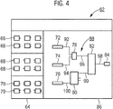
- Such a programming surface 62 shown on a screen 60 is shown in FIG FIG. 4 shown.
- the programming interface 62 has a first subarea 64, in which function blocks 66, 68, 70 are shown.
- the function blocks 66, 68, 70 are grouped into three groups.
- the first group comprises function blocks 66 to each of which an encoder is assigned, eg emergency stop switch single-channel, emergency stop switch dual-channel etc.
- These function blocks 66 symbolize an input signal of such a transmitter, wherein in the logic programming the hardware implemented redundancy (see above) is no longer visible to the user, since the error monitoring is performed by the firmware of the safety controller 1 even without separate programming itself.
- the user should only define how the operation of such an encoder works. So at the in FIG. 2 Although the two-channel emergency stop switch shown, although it actually comprises two redundant channels, in the logic programming on the programming interface 62 only a single output signal is displayed, which is then further linked in the logic.
- the second group of function blocks 68 comprises symbols which symbolize output signals to actuators.
- the above is analogous here.
- the third group includes functional blocks 70, which are logic devices. These can be simple logical combinations such as “AND” or “OR”, more complex evaluators such as flip-flops, clock generators or application-specific function blocks 70 for switch-off delays, presses, etc.
- the Function blocks 66, 68, 70 may also be subordinated according to further content criteria.
- the user now selects a function block 66, 68, 70 as part of the logic programming.
- the selection is made by moving the mouse pointer not shown in detail to the desired function block 66, 68, 70 and a simple mouse click on the respective desired function block 66, 68, 70.
- the selection by mouse click results in an instance 72-84 of the function block 66, 68, 70 is generated, which is attached to the mouse pointer.
- the instance 72-84 is generated because a plurality of similar function blocks 66, 68, 70 may be needed and therefore the same function block 66, 68, 70 may have to be selected multiple times in succession.
- the instance 72-84 may in this case be identical to the function block 66, 68, 70, but this need not be.
- the instances 72-84 are significantly wider and flatter than the function block 66, 68, 70 in order to possibly display text thereon. If the function block 66, 68, 70 contains a characteristic pictogram, this pictogram can also be displayed in embodiments on the instance 72-84, if necessary enlarged or reduced.
- For the determination of the logical connection is a in the second portion 86 of the programming interface 62 shown by the programmer using the instances 72 - 84 created logic diagram 88.
- the programming is based on graphical symbols that are logically linked by polyline.
- Input signals from encoders, represented by instances 72, 74, 76 from the function block symbols 66, are processed by logic blocks in the instances 78, 80 and processed into output signals for actuators, represented by instance 84.
- the depositing of the instances 72-84 takes place after selection of the function blocks 66, 68, 70 (see above) by simple drag-and-drop method.
- each function block 66, 68, 70 By simply connecting the signal inputs and outputs of each function block 66, 68, 70 to lines 90-100, the signals can be routed as desired.
- a logic diagram 88 is thus generated which defines the switching logic.
- the terminal assignments are defined, ie for such function blocks 66, 68, 70, which receive direct signals from physical input terminals or generate such signals for physical output terminals of the safety controller 1 is determined by a corresponding assignment of a terminal name, from which terminal the corresponding signal received or to which terminal it should be sent.
- the programming software executed on the computer 54 enables real-time execution of the created program.
- a second programming interface 102 is provided which in FIG. 5 is shown.
- the logic diagram 88 created in the first programming interface 62 is displayed in a first subregion 104 arranged on the right-hand side.
- buttons 108, 110, 112 which serve to control and later view a real-time execution of the program defined by the logic diagram 88.
- Real-time program execution means that the behavior of the safety controller 1 with the uploaded created program is mapped during operation of the safety controller 1.
- the real-time program execution is started by clicking on the first button 108 marked with a circle. It can be carried out in the described embodiment in two different ways: For the first type of real-time program execution, in the software that generates the programming surfaces 62, 102, an emulator module is included, which maps the function of the safety controller 1. Signals that are to be changed at runtime, eg at the encoders, can be simulated during the simulation by clicking on the corresponding instances 72, 74, 76. The program logic then executes the corresponding logical consequences resulting from the logic diagram 88 at the instance 84.
- the created program will be in the FIG. 3 described manner in the real safety controller 1 dubbed and set the safety controller 1 with connected encoders and possibly actuators in operation.
- the computer 54 Via the connection via the interface, the computer 54 has diagnostic access to the development of the logic states in the program and these are transmitted to the computer.
- variable input signals can be generated directly by actuating the encoders or by applying physical input signals to the terminals of the safety controller 1.
- the resulting temporal developments of the states at the individual inputs and outputs of the function blocks 66, 68, 70 representing instances 72-84, i. on the lines 90-100 are recorded in a ring memory in the computer 54 during program execution, and the contents of the ring memory are stored in a record after completion of the program execution, so that e.g. the last 30 minutes of the temporal development of all states on the lines 90-100 and possibly also internal states of individual instances 72-84 are contained.
- the real-time program execution record included in the data set can be re-presented by the user by clicking on a button 110 containing a right-hand triangle.
- the states are then represented in the logic diagram again as during real-time program execution.
- the disadvantage here is that the user usually wants to determine the leading to a specific effect causes that are due to the laws of causality before the effects.
- the programming interface 102 in the second portion 106 has a third button 112 with a leftward triangle.
- a mouse click on this button 112 causes the real-time program execution or the recording of the real-time program execution from the end of the program execution backwards is played.
- the presentation can therefore be navigated backwards in time.
- the user can immediately determine the causes leading to the state combination present at the end of the real-time program execution, since these only follow in the chronologically backward presentation.
- buttons 114, 116 and a selection field 118 are arranged.
- the plus-sign pointing button 114 the user can jump forward in discrete time increments, the size of which can be selected in selection box 118 (e.g., 500 ms, 1 s, 2 s), by recording the simulation.
- he can by means of a button 116, which shows a minus sign, jump backwards discretely in the recording.
- the temporally backward navigation thus includes, on the one hand, a reverse playback as well as a time-discrete jumping through the recording.
- the representation of the states in the recording takes place in the exemplary embodiment by means of a color coding.
- Each state is assigned a color, and while the simulation is playing, each line 90-100 is currently colored according to its actual state. If the status changes during program execution, the color in the recording also changes. Since lines 90-100 always terminate at one (or more) inputs or outputs of instances 72-84, this includes coloring these signal inputs and outputs.
- individual states can be selected by the user whose temporal development is shown in the form of graphs 122, 124, which plots the respective state versus time, represented by a scale 128.
- a line 130 shows in each case the current time during the playback of the recording, ie in the representation.
- the scale 128 moves with the graphs 124, 126 thereby forward in time or in the sense of solving the problem described above backwards.
- the user can also define in the programming interface 102 stop conditions that, when reached, result in an automatic stop of the real-time program execution. These can be defined, for example, by the definition of specific states at specific signal inputs or outputs. If the simulation is carried out by coupling the physical safety controller 1, the connection is disconnected via the interface at the time of stopping the program execution on the software side. The user can now accurately determine by means of the buttons 112, 116, the causes of reaching the stop condition.
- start conditions are also defined, ie each state input and output of each instance 72-84 is assigned a state where real-time program execution begins. This can be done manually or with default values. But it can also be about to FIG. 3 described interface transfer current values from the safety controller 1 and set on the programming interface 102. Alternatively, a state set may be extracted at a certain time of a recording and set as start conditions.
Landscapes
- Engineering & Computer Science (AREA)
- Theoretical Computer Science (AREA)
- Physics & Mathematics (AREA)
- General Engineering & Computer Science (AREA)
- General Physics & Mathematics (AREA)
- Software Systems (AREA)
- Computer Hardware Design (AREA)
- Quality & Reliability (AREA)
- Automation & Control Theory (AREA)
- Programmable Controllers (AREA)
Abstract
Description
- Die Erfindung betrifft ein Verfahren zum computergestützten Programmieren einer speicherprogrammierbaren Steuerung, wobei eine Programmieroberfläche auf einem Bildschirm eines Computers dargestellt wird, ein Programm für die speicherprogrammierbare Steuerung erstellt wird, indem auf der Programmieroberfläche Instanzen von Funktionsblöcken durch Verbinden ihrer jeweiligen Signalein- und -ausgänge anhand eines Logikschaltbildes logisch verknüpft werden, auf der Programmieroberfläche das erstellte Programm ausgeführt wird, und ein Datensatz erstellt wird, der die zeitliche Entwicklung der Zustände der Signalein- und -ausgänge während der Ausführung enthält.
- Eine speicherprogrammierbare Steuerung (SPS, englisch: Programmable Logic Controller, PLC) ist ein Gerät, das zur Steuerung oder Regelung einer Maschine oder Anlage eingesetzt und auf digitaler Basis programmiert wird. Sie weist im einfachsten Fall Anschlussklemmen (als Eingänge und/oder Ausgänge), ein Betriebssystem (Firmware) und eine Schnittstelle, über die das Programm geladen werden kann, auf. Das Programm legt fest, wie die Ausgänge in Abhängigkeit von den Eingängen geschaltet werden sollen. Das Betriebssystem (Firmware) stellt dabei sicher, dass dem Programm immer der aktuelle Zustand der an die Eingänge angeschlossenen Sensoren zur Verfügung steht. Anhand dieser Informationen kann das Programm die Ausgänge so schalten (und damit die dort angeschlossenen Aktoren so steuern), dass die Maschine oder die Anlage in der gewünschten Weise funktioniert.
- Die Anbindung der SPS an die Maschine bzw. Anlage erfolgt mittels der bereits erwähnten Sensoren und Aktoren. Die Sensoren sind an die Eingänge der SPS geschaltet und vermitteln der SPS das Geschehen in der Maschine oder Anlage. Beispiele für Sensoren sind z. B. Taster, Lichtschranken, Inkrementalgeber, Endschalter, oder auch Temperaturfühler, Füllstandssensoren etc. Die Aktoren sind an den Ausgängen der SPS angeschlossen und bieten die Möglichkeit, die Maschine oder Anlage zu steuern. Beispiele für Aktoren sind Schütze zum Einschalten von Elektromotoren, elektrische Ventile für Hydraulik oder Druckluft, aber auch Module für Antriebssteuerungen (Motion Control, Drehzahlsteuerung mit kontrollierter Beschleunigung oder Verzögerung, Schrittmotorsteuerungen).
- Die Erstellung des Programms für eine speicherprogrammierbare Steuerung erfolgt häufig über eine sogenannte Funktionsbausteinsprache, engl. "Function Block Diagram" auf einem Computer, wie dies in der Norm EN 61131-3 spezifiziert ist. Hierbei handelt es sich um eine graphisch orentierte Programmiersprache, bei der die Programmlogik auf einer Programmieroberfläche visualisiert wird. Die Programmieroberfläche stellt hierbei eine Menge von Funktionsblöcken mit Signalein- und -ausgängen bereit, die vom Benutzer ausgewählt werden können. Eine oder mehrere Instanzen der Funktionsblöcke werden auf der Programmieroberfläche angeordnet und und durch die Verbindung von Ausgängen mit Eingängen durch Linien in der Art eines Logikschaltbildes verbunden.
- Zur Fehlersuche und zur Überprüfung des Ablaufes des Programms ist es bekannt, das erstellte Programm testweise auszuführen, d.h. das erstellte Programm wird ausgeführt, ohne dass durch die dadurch entstehenden Ausgangssignale eine Maschine gesteuert wird. Vielmehr wird nur die logische Verschaltung, d.h. die Wirkung der Eingänge auf die Ausgänge geprüft. Zum Zwecke dieser Überprüfung der logischen Verknüpfung ist es bekannt die Zustände der Signalein- und -ausgänge der Funktionsblöcke, die letztlich den Zuständen auf den Verbindungslinien entsprechen, während der Ausführung aufzuzeichnen und ihren zeitlichen Verlauf in einem Datensatz abzuspeichern. Dadurch kann die Aufzeichnung zu einem späteren Zeitpunkt z.B. erneut abgespielt werden. Problematisch ist hierbei, dass bei großen und komplexen Logikschaltplänen eine Fehlersuche und -erkennung schwierig ist und ggf. Fehler in der Programmierung nicht oder nur mit großem Aufwand anhand der Aufzeichnung erkannt werden.
- Es ist daher Aufgabe der Erfindung, ein Verfahren der eingangs genannten Art anzugeben, welches die Programmierung der Steuerung auf besonders einfache Art und Weise erlaubt und Fehler im Betrieb der speicherprogrammierbaren Steuerung vermeidet.
- Diese Aufgabe wird erfindungsgemäß gelöst, indem aus dem Datensatz eine zeitlich rückwärts navigierbare Darstellung der Entwicklung der Zustände der Signalein- und -ausgänge erstellt und auf der Programmieroberfläche angezeigt wird.
- Die Erfindung geht dabei von der Überlegung aus, dass bisher verfügbare Simulationen und deren Darstellungen dem Programmierer den Ablauf des Programms in kausaler Reihenfolge zeigen: Ein bestimmter Eingang ändert seinen Wert, z.B. durch bestimmte Eingangssignale eines Sensors, und anschließend führt dies über verschiedene Programmabläufe in zwischengeschalteten Funktionsblöcken zu bestimmten Ausgangssignalen. Die Simulation zeichnet also die Ereignisse in der Reihenfolge ihres Geschehens auf, d.h. stets zuerst die Ursache, dann die Wirkung. Für den Programmierer ist es im Rahmen der Fehlersuche und des sogenannten Debuggings aber in der Regel entscheidend herauszufinden, welche Ursachen zu einer bestimmten (fehlerhaften) Wirkung geführt haben. Für ihn sind also die ursächlichen Signale und Ereignisse unmittelbar vor dem Eintreten der fehlerhaften Wirkung im Rahmen der Erstellung des Programms entscheidend. Das Auffinden dieser Ursachen sollte daher im Rahmen des Debuggings dadurch erleichtert werden, dass dem Programmierer nach Identifikation der fehlerhaften Wirkung im Anschluss diejenigen Ursachen aufgezeigt werden, die zu dieser Wirkung geführt haben. Hierzu sollte die Reihenfolge von Ursache und Wirkung in der Darstellung umgekehrt werden. Dies ist erreichbar, indem aus dem Datensatz, der die zeitliche Entwickung der Zustände der Signalein- und -ausgänge enthält, eine zeitlich rückwärts navigierbare Darstellung deren Entwicklung erstellt und angezeigt wird. Mit anderen Worten: Auf der Programmieroberfläche wird eine Darstellung erzeugt, die gegenüber dem Ausführungsablauf die Zustände und deren Veränderungen in umgekehrter zeitlicher Reihenfolge anzeigbar macht. Der Benutzer kann den aufgezeichneten Ausführungsablauf des Programmes also nicht nur wie bisher nachverfolgen, dabei allenfalls pausieren, sondern er kann den Programmablauf rückwärts beobachten und beliebig in der in der Zeit vor- und rückwärts springen.
- In vorteilhafter Ausgestaltung der Erfindung wird in der Darstellung die Entwicklung der Zustände der Signalein- und -ausgänge zeitlich veränderlich innerhalb des Logikschaltbildes angezeigt. D.h., die während der Ausführung aufgenommene und im Datensatz gespeicherte zeitliche Entwicklung der Zustände der Signalein- und -ausgänge wird wiederum zeitlich veränderlich innerhalb des Logikschaltbildes angezeigt. D.h., beim zeitlich rückwärts Navigieren oder Abspielen des aufgezeichneten Ausführungsablaufes werden die jeweiligen Zustände an den Signalein- und -ausgängen im Logikschaltbild gezeigt, z.B. anhand von Anzeigeflächen in unmittelbarer Nähe der Ein- oder Ausgänge, in denen der zu einem Zeitpunkt jeweils aktuelle Zustand angezeigt wird.
- In besonders vorteilhafter Ausgestaltung werden die jeweiligen Zustände dabei mittels einer Farbcodierung der Signalein- und -ausgänge angezeigt. D.h., für jeden Zustand wird ein Farbton festgelegt, z.B. rot für eine logische 0 und grün für eine logische 1, und die Signaleingänge werden jeweils zeitaktuell in den entsprechenden, dem aktuellen Zustand zugeordneten Farben dargestellt. In noch weiterer vorteilhafter Ausgestaltung werden dabei auch die die Ein- und Ausgänge verbindenden Linien im Logikschaltplan in der entsprechenden Farbe angezeigt.
- In zusätzlicher oder alternativer Ausgestaltung des Verfahrens wird in der Darstellung die Entwicklung der Zustände der Signalein- und -ausgänge zeitlich veränderlich anhand eines Graphen angezeigt, der den jeweiligen Zustand gegen die Zeit aufträgt. Ein solcher Graph kann bei einer zeitlich rückwärts navigierbaren Darstellung z.B. durch einen Anzeiger gekennzeichnet sein, der den aktuellen Zeitpunkt anzeigt und sich während des Ablaufs in der Zeit rückwärts entlang der Skala bewegt. Auch ein zeitliches Mitlaufen des zeitlichen Skalenausschnitts ist vorteilhaft.
- In einer ersten vorteilhaften Ausgestaltung des Verfahrens wird das erstellte Programm mithilfe eines softwarebasierten Emulators ausgeführt. D.h., dass in der Programmiersoftware, die auch die Programmieroberfläche erzeugt, auch ein Emulationsmodul enthalten ist, welches die Hardware und Firmware der speicherprogrammierbaren Steuerung emuliert. Das Programm wird dann in dieses Emulationsmodul geladen und dort ausgeführt - in gleicher Weise wie dies in der realen Steuerung geschehen würde. Auf diese Weise kann der Programmablauf simuliert werden, ohne dass die körperliche Anwesenheit der speicherprogrammierbaren Steuerung erforderlich wäre.
- In einer zweiten, alternativen vorteilhaften Ausgestaltung des Verfahrens wird das erstellte Programm ausgeführt, indem das erstellte Programm in die speicherprogrammiere Steuerung überspielt und dort ausgeführt wird, wobei die Zustände der Signalein- und -ausgänge über eine Diagnoseschnittstelle von dem Computer empfangen werden. Das erstellte Programm läuft also in der physisch vorhandenen, speicherprogrammierbaren Steuerung ab. Die dabei erzeugten Zustände der Signalein- und -ausgänge der Funktionsblocks und ihr zeitlicher Ablauf wird dabei über eine Diagnoseschnittstelle an den Computer und die dort ablaufende Programmiersoftware überspielt. Dies kann z.B. per Kabelverbindung oder drahtlos geschehen, idealerweise über denselben Verbindungsweg, mit dem auch das Programm in die Steuerung übertragen wird. Dadurch ist es auch möglich, das erstellte Programm bereits mit realen, physisch vorhandenen und an die Steuerung angeschlossenen Sensoren/Aktoren auszuführen.
- In weiterer vorteilhafter Ausgestaltung wird dabei eine Anhaltebedingung definiert und der Datensatz enthält die zeitliche Entwicklung der Zustände der Signalein- und -ausgänge bis zum Erreichen der Anhaltebedingung. Mit anderen Worten: Die Aufnahme der Ausführung des Programms im Datensatz endet bei Erreichen der Anhaltebedingung. Die Anhaltebedingung kann beliebig definiert sein, wird aber in der Regel bestimmte Zustände an bestimmten Ein-/Ausgängen definieren. Eine derartige Ausgestaltung ist besonders vorteilhaft, wenn der Programmierer ermitteln will, welche Programmabläufe zu einem bestimmten Zustand geführt haben. Dieser Zustand wird vom Benutzer als Anhaltebedingung definiert. Die Erstellung des Datensatzes wird dann an der Stelle des Erreichens dieses Zustandes beendet und die zeitlich rückwärts navigierbare Darstellung wird von dieser Stelle an erstellt. Somit ermöglicht die zeitlich rückwärts navigierbare Darstellung ein präzises Nachvollziehen der logischen Schaltvorgänge direkt vor Erfüllen der definierten Anhaltebedingung.
- Vorteilhafterweise wird die zeitliche Entwicklung der Zustände der Signalein- und - ausgänge während des Ausführens des erstellten Programms dabei in einem Ringspeicher gespeichert und der Datensatz wird aus dem Inhalt des Ringspeichers bei Erreichen der Anhaltebedingung gebildet. Ein Ringspeicher eignet sich für den hier beschriebenen Zweck in besonderer Weise: Im Ringspeicher werden bei Erreichen des Speichermaximums stets die ältesten Daten überschrieben, d.h. der Ringspeicher enthält stets eine bestimmte Zeitspanne bis zum aktuellen Zeitpunkt der Programmausführung. Damit ist garantiert, dass bei Erreichen der Anhaltebedingung die dazu führenden logischen Programmabläufe stets im Datensatz enthalten sind.
- Wird das erstellte Programm mittels der realen speicherprogrammierbaren Steuerung ausgeführt, wird vorteilhafterweise bei Erreichen der Anhaltebedingung der Empfang der Zustände der Signalein- und -ausgänge über eine Diagnoseschnittstelle von dem Computer beendet. D.h., im Moment des Erreichens der Anhaltebedingung wird die Verbindung zur Steuerung getrennt und der weitere Zufluss von Daten beendet. Ab diesem Zeitpunkt wird die zeitlich rückwärts navigierbare Darstellung erstellt und es können die logischen Vorgänge bei rückwärtiger Bewegung durch die Zeit analysiert werden.
- Für den Beginn der Ausführung des Programms ist es notwendig, Startbedingungen zu definieren, d.h. Zustände der Signalein- und -ausgänge beim Start der Programmausführung. In einer ersten vorteilhaften Ausgestaltung werden diese aus der speicherprogrammierbaren Steuerung über eine Diagnoseschnittstelle von dem Computer empfangen. D.h., dass die Startbedingungen der realen Steuerung mit den Zuständen angeschlossener Geber etc. auch für die Ausführung des Programms unabhängig vom Ort der Ausführung (im Emulatormodul oder auf der Steuerung selbst) verwendet werden. Der Empfang der Startbedingungen erfolgt dabei idealerweise über dieselbe Schnittstelle, über die auch das Programm in die Steuerung übertragen wird.
- In einer zweiten vorteilhaften Ausgestaltung werden die Zustände der Signalein- und -ausgänge beim Start des Ausführens des Programms aus einem Datensatz gebildet werden, der die zeitliche Entwicklung der Zustände der Signalein- und - ausgänge während einer zuvor erfolgten Ausführung des Programms enthält. Mit anderen Worten: Es wird eine Menge von Zuständen als Startbedingung für die neue Simulation verwendet, die zu einem gegebenen Zeitpunkt in einer zuvor durchgeführten Programmausführung bestand. Wenn z.B. durch einen zuvor durchgeführten Programmablauf ein Fehler in der Logikprogrammierung aufgedeckt und korrigiert wurde, kann der neue Programmablauf an einem Punkt kurz vor dem Entstehen des Fehlers mit der korrigierten Logik neu gestartet bzw. weitergeführt werden und es ist unmittelbar erkennbar, ob der Fehler immer noch besteht.
- In weiterer vorteilhafter Ausgestaltung werden die Zustände der Signalein- und - ausgänge unmittelbar vor dem Start des Ausführens des Programms durch einen manuellen Benutzereingriff geändert. D.h., dass nach Festlegen der Startbedingungen aus der realen Steuerung oder einer vorherigen Simulation vor dem Start der aktuellen Programmausführung noch ein manueller Benutzereingriff z.B. durch manuelle Änderung einzelner Zustände erfolgen kann. Hierdurch ist es möglich, eine zuvor durchgeführte Programmausführung an einer bestimmten Stelle neu zu starten und mittels gezielter Änderung einzelner Zustände einen alternativen Pfad der Zukunft zu beschreiten und in der oben beschriebenen Weise zu analysieren.
- In besonders vorteilhafter Ausgestaltung ist die speicherprogrammierbare Steuerung nach einer Sicherheitsnorm funktional sicher ausgebildet. Gerade bei solchen Steuerungen, die im industriellen Bereich verwendet werden, ist eine Erleichterung der Fehlersuche von besonderer Wichtigkeit: Hier besteht bei Maschinen und deren Steuerung nämlich häufig der Bedarf nach einer Sicherheitsfunktion, d.h. einer Sicherstellung einer störungsfreien und insbesondere gefahrenfreien Funktion. Es handelt sich in der Regel um Maschinen, die Gefahrenpotential für Mensch und Material bergen, d.h. z.B. Pressen, Fräswerkzeuge etc., so dass das Auftreten von Fehlern unbedingt sicher vermieden werden muss. Die wichtigsten Normen im Bereich der Maschinensicherheit sind die IEC 61508, die EN 62061 und die EN ISO 13849-1.
- Ein Computerprogrammprodukt, welches direkt in den internen Speicher eines Computers geladen werden kann, umfasst vorteilhafterweise Softwarecodeabschnitte, die, wenn sie auf dem Computer ausgeführt werden, den Computer zum Ausführen des beschriebenen Verfahrens ertüchtigen.
- In den internen Speicher eines Computers ist vorteilhafterweise das beschriebene Computerprogrammprodukt geladen.
- Die mit der Erfindung erzielten Vorteile bestehen insbesondere darin, dass durch die zeitlich rückwärts navigierbare Darstellung einer Programmausführung während der Programmierung einer Sicherheitssteuerung eine Analyse der zu einem bestimmten Fehler führenden Ursachen ausgehend von der beobachteten Wirkung erfolgen kann. Dadurch kann eine Programmierung der Sicherheitssteuerung schneller, sicherer und fehlerunanfälliger durchgeführt werden.
- Ein Ausführungsbeispiel der Erfindung wird anhand von Zeichnungen näher erläutert. Darin zeigen:
- FIG 1
- eine schematische Darstellung einer modularen Sicherheitssteuerung,
- FIG 2
- eine schematische Darstellung der modularen Sicherheitssteuerung in einer Betriebsart mit einem redundanten Schalter,
- FIG 3
- eine schematische Darstellung der Sicherheitssteuerung mit einem zur Programmierung ausgerüsteten digitalen Computer,
- FIG 4
- eine schematische Darstellung einer Programmieroberfläche zur Erstellung eines Logikschaltbildes, und
- FIG 5
- eine schematische Darstellung einer Programmieroberfläche für eine Echtzeit-Programmausführung.
- Gleiche Teile sind in allen Zeichnungen mit denselben Bezugszeichen versehen.
- Die
FIG 1 zeigt schematisch eine modulare Sicherheitssteuerung 1, umfassend ein Kopfmodul 2, ein Eingangserweiterungsmodul 4 und ein Ausgangserweiterungsmodul 6, die über einen Rückwandbus 8 datenseitig miteinander verbunden sind. Im Kopfmodul 2 ist eine zentrale Steuereinheit 10 angeordnet, die die Eingangssignale verarbeitet und daraus Ausgangssignale erzeugt. Die Sicherheitssteuerung 1 ist eine speicherprogrammierbare Steuerung, die zusätzlich gemäß der Norm EN ISO 13849-1 ausgestaltet, d.h. funktional sicher ist. Dies wird neben anderen Maßnahmen durch die sogenannte überwachte Redundanz gewährleistet, d.h. die Steuereinheit 2 umfasst zwei nicht näher gezeigte, redundant arbeitende Mikrocontroller, deren Ergebnisse permanent abgeglichen und auf Übereinstimmung geprüft werden. - Die Sicherheitssteuerung 1 weist eine Vielzahl von Klemmen 12 - 38 auf, von denen sechs Klemmen 12 - 22 am Kopfmodul 2, vier Klemmen 24 - 30 am Eingangserweiterungsmodul 4 und vier Klemmen 32 - 38 am Ausgangserweiterungsmodul 6 angeordnet sind. Die Steuereinheit 10 kann über den Rückwandbus 8 und ggf. weitere Prozessoreinheiten in den Erweiterungsmodulen 4, 6 jede der Klemmen 12 - 38 ansteuern bzw. abrufen.
- Die Klemmen 32 - 38 des Ausgangserweiterungsmoduls 6 können paarweise in die Stromzufuhr zu einem nicht näher gezeigten Aktor geschaltet werden, der einen elektrischen Verbraucher schaltet, der Gefahrenpotential aufweist und daher sicher ausgeschaltet werden soll. Dazu sind in die Verbindung zwischen den Klemmen 32, 34 bzw. 36, 38 jeweils zwei Relais 40, 42 bzw. 44, 46 in Reihe geschaltet. Um den Stromfluss zu erhalten, müssen beide Relais 40, 42 bzw. 44, 46 im geschlossenen Zustand sein, sie sind also redundant. Die Relais 40, 42 bzw. 44, 46 werden von den redundanten Mikrocontrollern der Steuereinheit 10 unabhängig gesteuert.
- Um die Funktion des elektrischen Verbrauchers im Gefahrenfall zu unterbrechen oder zumindest zu beeinflussen, sind verschiedene, beispielhaft in der folgenden
FIG 2 , jedoch nicht in derFIG 1 gezeigte Geber an die Sicherheitssteuerung 1 anschließbar. Diese können z.B. Not-Aus-Schalter, Lichtschranken, Türpositionsschalter etc. sein. Zum Anschluss dieser Geber weist die Sicherheitssteuerung 1 neben den Klemmen 24 - 30 am Eingangserweiterungsmodul 4 auch Klemmen 12 - 22 auf, die die Geber mit Strom versorgen können. An einigen dieser Klemmen 12 - 22 liegt im Ausführungsbeispiel stets eine kleine positive Gleichspannung an, dies ist jedoch nicht zwingend, z.B. bei sog. Open-Collector oder Tri State-Ausgängen. Alternativ können an anderen dieser Klemmen 12 - 22 auch Prüfsignale mit zyklischen, pulsartigen Prüfpulsen zur Leitungs- und Kurzschlussprüfung vorgesehen sein, die jeweils für eine kurze Dauer 0 Volt über der sonst erhaltenen Grundspannung einstellen. Die Prüfpulse können alternativ auch auf einen Trigger wie z.B. eine manuelle oder automatische veranlasste Prüfanfrage hin abgegeben werden. Alle Klemmen 12 - 38 können hardwareseitig beliebig, z.B. als Schraub- oder Federklemmen ausgestaltet sein. -
FIG 2 zeigt ein Anwendungsbeispiel der Sicherheitssteuerung 1 im Gutzustand. Dabei wird aus Gründen der Übersichtlichkeit auf die Darstellung sämtlicher Teile der Sicherheitssteuerung 1 verzichtet und es wird nur ein Ausschnitt der Sicherheitssteuerung gezeigt. -
FIG 2 zeigt einen Not-Aus-Schalter 48, der zwei redundante Kanäle mit zwei mechanisch verbundenen Schaltern 50, 52 umfasst. Die Schalter 50, 52 sind äquivalent, d.h. beide im Gutzustand geschlossen und im Zustand der Anforderung der Sicherheitsfunktion geöffnet. Hier ist der Not-Aus-Schalter 48 derart mit dem Sicherheitssteuerung 1 verbunden, dass Klemme 16 über den einen der Schalter 50 mit Klemme 26 verbunden ist, Klemme 14 über den anderen der Schalter 52 mit Klemme 24. Auf den Klemmen 24, 26 ergibt sich bei Freigabe somit die Signalkombination Plus, Plus, im Zustand der Anforderung der Sicherheitsfunktion die Signalkombination Null, Null. Andere Signalkombinationen deuten auf einen Fehler hin. In beiden letztgenannten Fällen wird eine Unterbrechung der Stromzufuhr des jeweils durch die noch im Folgenden erläuterte Logikprogrammierung mit dem Not-Aus-Schalter 48 verknüpften Stromkreises im Ausgangserweiterungsmodul 6 veranlasst, beispielsweise zwischen den Klemmen 36 und 38. - Das Beispiel in den
FIG 1 und 2 dient nur der Veranschaulichung der Funktionsweise der Sicherheitssteuerung 1 und ist daher stark vereinfacht. In der Realität wird das System weit komplexer sein, d.h. es werden wesentlich mehr Module und Module anderer Art (z.B. sogenannten Gateway-Module für Schnittstellen zu Feldbussen) vorhanden sein, und es werden eine Vielzahl weiterer Klemmen auf verschiedenen Modulen vorhanden sein, die eine Vielzahl von elektrischen Verbrauchern schalten können und an die eine Vielzahl von Gebern und Aktoren verschiedenster Art angeschlossen werden kann. Auch müssen die Klemmen nicht notwendig nur eine Funktion erfüllen sondern können ggf. auch variabel als Ein- oder Ausgangsklemmen verwendet werden. - Die Klemmenbelegung und damit letztlich die an den Klemmen zu erwartenden Signalkombinationen sowie die logische Verknüpfung zwischen den Geber- und Aktorsignalen müssen in der Steuereinheit 10 der Sicherheitssteuerung 1 hinterlegt sein, so dass diese bei entsprechender Signalisierung die Abschaltung der richtigen elektrischen Verbraucher veranlasst. Dies geschieht durch Übergabe einer entsprechenden Konfiguration an eine in der Steuereinheit 10 hinterlegte Firmware. Da die Konfiguration letztlich die gesamten logischen Verknüpfungen zwischen Gebern und Aktoren festlegt, wird sie im Folgenden vereinfachend als Programm bezeichnet.
- Die Erstellung dieses Programms erfolgt an einem digitalen Computer 54, der in
FIG 3 gezeigt ist. Der Computer 54 weist Eingabegeräte wie eine Tastatur 56 und eine Maus 58 auf sowie einen Bildschirm 60 als Ausgabegerät. Über eine serielle oder parallele Schnittstelle oder z.B. über Ethernet ist er mit der Sicherheitssteuerung 1 verbunden. Auf dem Computer 54 wird durch einen Benutzer auf einer graphischen Programmieroberfläche anhand der angedachten Geber- und Aktorkombination sowie der gewünschten logischen Verknüpfung das Programm erstellt, geprüft und anschließend in die Steuereinheit 10 der Sicherheitssteuerung 1 übertragen. In einer alternativen, nicht gezeigten Ausführungsform kann der digitale Computer 54 auch als Tablet mit Touchscreen ausgestaltet sein. Insofern im Folgenden im Ausführungsbeispiel von Mausklick oder Mausbewegung gesprochen wird, wäre dies im Falle eines Tablets durch Antippen und entsprechendes Ziehen des Fingers durchzuführen. - Eine solche, auf einem Bildschirm 60 dargestellte Programmieroberfläche 62 ist in der
FIG 4 gezeigt. Die Programmieroberfläche 62 weist einen ersten Teilbereich 64 auf, in dem Funktionsblöcke 66, 68, 70 dargestellt sind. Die Funktionsblöcke 66, 68, 70 sind dabei in drei Gruppen gruppiert. Die erste Gruppe umfasst Funktionsblöcke 66, denen jeweils ein Geber zugeordnet ist, z.B. Not-Aus-Schalter einkanalig, Not-Aus-Schalter zweikanalig etc. Diese Funktionsblöcke 66 symbolisieren ein Eingangssignal eines solchen Gebers, wobei in der Logikprogrammierung die hardwareseitig realisierte Redundanz (siehe oben) bereits nicht mehr für den Benutzer ersichtlich ist, da die Fehlerüberwachung von der Firmware der Sicherheitssteuerung 1 auch ohne gesonderte Programmierung selbst geleistet wird. Der Benutzer soll im Rahmen der Programmierung nur festlegen, wie die Betätigung eines solchen Gebers wirkt. So würde beim inFIG 2 gezeigten zweikanaligen Not-Aus-Schalter, obwohl dieser real zwei redundante Kanäle umfasst, in der Logikprogrammierung auf der Programmieroberfläche 62 nur ein einzelnes Ausgangssignal angezeigt, welches dann in der Logik weiter verknüpft wird. - Entsprechend umfasst die zweite Gruppe von Funktionsblöcke 68 solche Symbole, die Ausgangssignale an Aktoren symbolisieren. Das oben Gesagte gilt hier analog. Die dritte Gruppe umfasst schließlich Funktionsblöcke 70, die Logikbausteine sind. Diese können einfache logische Kombinationen wie "UND" oder "ODER" sein, komplexere Auswerter wie Flip-Flops, Taktgeneratoren oder aber applikationsspezifische Funktionsblöcke 70 für Abschaltverzögerungen, Pressen etc. In nicht gezeigten Ausführungsbeispielen können die Funktionsblöcke 66, 68, 70 auch nach weiteren inhaltlichen Kriterien untergruppiert sein.
- Der Benutzer wählt im Rahmen der Logikprogrammierung nun einen Funktionsblock 66, 68, 70 aus. Die Auswahl erfolgt durch Bewegen des nicht näher dargestellten Mauszeigers auf den gewünschten Funktionsblock 66, 68, 70 und einfachen Mausklick auf den jeweils gewünschten Funktionsblock 66, 68, 70. Die Auswahl durch Mausklick führt dazu, dass eine Instanz 72 - 84 des Funktionsblocks 66, 68, 70 erzeugt wird, die an den Mauszeiger angeheftet wird.
- Die Instanz 72 - 84 wird erzeugt, da mehrere gleichartige Funktionsblöcke 66, 68, 70 benötigt werden können und daher ggf. mehrfach nacheinander der gleiche Funktionsblock 66, 68, 70 ausgewählt werden muss. Die Instanz 72 - 84 kann in ihrer Darstellung dabei identisch mit dem Funktionsblock 66, 68, 70 sein, muss dies aber nicht. Im Ausführungsbeispiel sind die Instanzen 72 - 84 deutlich breiter und flacher als der Funktionsblock 66, 68, 70, um ggf. Text darauf darzustellen. Enthält der Funktionsblock 66, 68, 70 ein kennzeichnendes Piktogramm, so kann dieses Piktogramm in Ausführungsformen auch auf der Instanz 72 - 84 ggf. vergrößert oder verkleinert, dargestellt werden.
- Für die Festlegung der logischen Verknüpfung dient ein im zweiten Teilbereich 86 der Programmieroberfläche 62 dargestelltes, vom Programmierer mithilfe der Instanzen 72 - 84 erstelltes Logikschaltbild 88. Im Logikschaltbild 88 erfolgt die Programmierung anhand graphischer Symbole, die logisch durch Linienzug verknüpft werden. Eingangssignale von Gebern, repräsentiert durch Instanzen 72, 74, 76 aus den Funktionsbausteinsymbolen 66 werden durch Logikbausteine in den Instanzen 78, 80 verarbeitet und in Ausgangssignale für Aktoren, repräsentiert durch Instanz 84, verarbeitet. Die Hinterlegung der Instanzen 72 - 84 erfolgt nach Auswahl der Funktionsblöcke 66, 68, 70 (siehe oben) durch einfaches Drag-and-Drop-Verfahren. Durch einfaches Verbinden der Signalein- und -ausgänge jedes Funktionsblocks 66, 68, 70 mit Linien 90 - 100 können die Signale wie gewünscht weitergeleitet werden. Durch geschickte Auswahl und Kombination von Funktionsblöcken 66, 68, 70 und entsprechende Verbindung der Instanzen 72 - 84 wird somit ein Logikschaltbild 88 erzeugt, das die Schaltlogik definiert. Zusätzlich werden die Klemmenzuordnungen festgelegt, d.h. für solche Funktionsblöcke 66, 68, 70, welche direkte Signale von physikalischen Eingangsklemmen empfangen oder solche Signale für physikalische Ausgangsklemmen der Sicherheitssteuerung 1 erzeugen sollen, wird über eine entsprechende Zuordnung einer Klemmenbezeichnung festgelegt, von welcher Klemme das entsprechende Signal empfangen bzw. an welche Klemme es gesendet werden soll.
- Für größtmögliche Fehlervermeidung und die Möglichkeit der Fehlersuche ermöglicht die auf dem Computer 54 ausgeführte Programmiersoftware eine Echtzeit-Ausführung des erstellten Programms. Hierfür wird eine zweite Programmieroberfläche 102 bereitgestellt, die in
FIG 5 gezeigt ist. Auf der zweiten Programmieroberfläche 102 wird in einem ersten, auf der rechten Seite angeordneten Teilbereich 104 das in der ersten Programmieroberfläche 62 erstellte Logikschaltbild 88 dargestellt. In einem zweiten Teilbereich 106 sind Schaltflächen 108, 110, 112 dargestellt, die zur Steuerung und späteren Ansicht einer Echtzeit-Ausführung des durch das Logikschaltbild 88 definierten Programms dienen. Echtzeit-Programmausführung heißt, dass das Verhalten der Sicherheitssteuerung 1 mit dem aufgespielten erstellten Programm während des Betriebs der Sicherheitssteuerung 1 abgebildet wird. - Die Echtzeit-Programmausführung wird durch Mausklick auf die erste, mit einem Kreis markierte Schaltfläche 108 gestartet. Sie kann in der beschriebenen Ausführungsform auf zwei verschiedene Arten durchgeführt werden: Für die erste Art der Echtzeit-Programmausführung ist in der Software, die die Programmieroberflächen 62, 102 erzeugt, ein Emulatormodul enthalten, welches die Funktion der Sicherheitssteuerung 1 abbildet. Signale, die während der Laufzeit z.B. an den Gebern geändert werden sollen, können während des Ablaufs der Simulation durch Mausklick auf die entsprechenden Instanzen 72, 74, 76 simuliert werden. Die Programmlogik führt dann die entsprechenden logischen Konsequenzen, die sich durch das Logikschaltbild 88 an der Instanz 84 ergeben, aus.
- Für die zweite Art der Echtzeit-Programmausführung wird das erstellte Programm in der zu
FIG 3 beschriebenen Weise in die reale Sicherheitssteuerung 1 überspielt und die Sicherheitssteuerung 1 mit angeschlossenen Gebern und ggf. Aktoren in Betrieb gesetzt. Über die Verbindung über die Schnittstelle hat der Computer 54 diagnoseseitig Zugriff auf die Entwicklung der logischen Zustände im Programm und diese werden in den Computer übertragen. Hierbei können veränderliche Eingangssignale direkt durch Betätigung der Geber oder durch Aufbringen physikalischer Eingangssignale an den Klemmen der Sicherheitssteuerung 1 erzeugt werden. - Die hierbei sich ergebenden zeitlichen Entwicklungen der Zustände an den einzelnen Ein- und -Ausgängen der Funktionsblöcke 66, 68, 70 repräsentierenden Instanzen 72 - 84, d.h. an den Linien 90 - 100 werden während der Programmausführung im Computer 54 in einem Ringspeicher aufgezeichnet und der Inhalt des Ringspeichers wird nach Beenden der Programmausführung in einem Datensatz hinterlegt, so dass z.B. die letzten 30 Minuten der zeitlichen Entwicklung aller Zustände auf den Linien 90 - 100 und ggf. auch internen Zuständen von einzelnen Instanzen 72 - 84 enthalten sind.
- Die im Datensatz enthaltene Aufzeichnung der Echtzeit-Programmausführung kann durch den Benutzer durch Mausklick auf eine ein nach rechts gerichtetes Dreieck enthaltende Schaltfläche 110 erneut dargestellt werden. Die Zustände werden dann im Logikschaltbild wieder so dargestellt, wie während der Echtzeit-Programmausführung. Nachteilig ist hierbei, dass der Benutzer üblicherweise die zu einer bestimmten Wirkung führenden Ursachen ermitteln will, die aufgrund der Gesetze der Kausalität vor den Wirkungen liegen.
- Zur Lösung dieses Problems weist die Programmieroberfläche 102 im zweiten Teilbereich 106 eine dritte, mit einem nach links gerichteten Dreieck versehene Schaltfläche 112 auf. Ein Mausklick auf diese Schaltfläche 112 führt dazu, dass die Echtzeit-Programmausführung bzw. die Aufnahme der Echtzeit-Programmausführung ausgehend vom Ende der Programmausführung rückwärts abgespielt wird. Die Darstellung ist also zeitlich rückwärts navigierbar. Dadurch kann der Benutzer unmittelbar die zu der am Ende der Echtzeit-Programmausführung vorliegenden Zustandskombination führenden Ursachen ermitteln, da diese in der zeitlich rückwärtigen Darstellung erst folgen.
- Im dritten Teilbereich sind weitere Schaltflächen 114, 116 sowie ein Auswahlfeld 118 angeordnet. Mittels der ein Plus-Zeichen zeigenden Schaltfläche 114 kann der Benutzer in diskreten Zeitschritten, deren Größe im Auswahlfeld 118 ausgewählt werden kann (z.B. 500 ms, 1 s, 2 s) vorwärts durch die Aufzeichnung der Simulation springen. Im Sinne der Lösung des genannten Problems kann er mittels einer Schaltfläche 116, die ein Minus-Zeichen zeigt, zeitlich rückwärts diskret in der Aufzeichnung springen. Die zeitlich rückwärtige Navigierung umfasst also einerseits ein Rückwärts-Abspielen als auch ein zeitlich diskretes Springen durch die Aufzeichnung.
- Die Darstellung der Zustände in der Aufzeichnung erfolgt im Ausführungsbeispiel mittels einer Farbcodierung. Jedem Zustand ist eine Farbe zugeordnet und während des Abspielens der Simulation wird jede Linie 90 - 100 aktuell nach ihrem tatsächlichen Zustand eingefärbt. Ändert sich während der Programmausführung der Zustand, ändert sich also auch die Farbe in der Aufzeichnung. Da die Linien 90 - 100 stets an einem (oder mehreren) Ein- oder Ausgängen von Instanzen 72 - 84 enden, schließt dies die Einfärbung dieser Signalein- und -ausgänge mit ein.
- Zusätzlich können auf der Programmieroberfläche 102 in einem dritten Teilbereich vom Benutzer einzelne Zustände ausgewählt werden, deren zeitliche Entwicklung in Form von Graphen 122, 124 dargestellt ist, die den jeweiligen Zustand gegen die Zeit, dargestellt anhand einer Skala 128, aufträgt. Eine Linie 130 zeigt dabei jeweils den aktuellen Zeitpunkt während des Abspielens der Aufzeichnung, d.h. in der Darstellung. Die Skala 128 bewegt sich mit den Graphen 124, 126 dabei zeitlich vorwärts oder im Sinne der Lösung des oben beschriebenen Problems rückwärts.
- Im Rahmen der Echtzeit-Programmausführung können durch den Benutzer in der Programmieroberfläche 102 auch Anhaltebedingungen definiert werden, bei deren Erreichen ein automatischer Stop der Echtzeit-Programmausführung erfolgt. Diese können beispielsweise durch die Festlegung bestimmter Zustände an bestimmten Signalein- oder -ausgängen definiert sein. Erfolgt die Simulation mittels Ankopplung der physikalischen Sicherheitssteuerung 1, wird die Verbindung über die Schnittstelle zum Zeitpunkt des Anhaltens der Programmausführung softwareseitig getrennt. Der Benutzer kann nun zielgenau mittels der Schaltflächen 112, 116 die Ursachen des Erreichens der Anhaltebedingung ermitteln.
- Für die Programmausführung werden zudem Startbedingungen definiert, d.h. jedem Signalein- und -ausgang jeder Instanz 72 - 84 wird ein Zustand zugeordnet, bei dem die Echtzeit-Programmausführung beginnt. Dies kann manuell oder mit Default-Werten geschehen. Es können aber auch über die zu
FIG 3 beschriebene Schnittstelle aktuelle Werte aus der Sicherheitssteuerung 1 übertragen und auf der Programmieroberfläche 102 eingestellt werden. Alternativ kann eine Zustandsmenge zu einem bestimmten Zeitpunkt einer Aufzeichnung extrahiert werden und als Startbedingungen festgelegt werden. - In beiden Fällen ist es möglich, vor dem erneuten Start der Echtzeit-Programmausführung manuell einzelne Zustände noch einmal zu ändern, so dass ggf. alternative Pfade des Programmablaufs getestet werden können.
-
- 1
- Sicherheitssteuerung
- 2
- Kopfmodul
- 4
- Eingangserweiterungsmodul
- 6
- Ausgangserweiterungsmodul
- 8
- Rückwandbus
- 10
- Steuereinheit
- 12 - 38
- Klemme
- 40 - 46
- Relaus
- 48
- Not-Aus-Schalter
- 50, 52
- Schalter
- 54
- Computer
- 56
- Tastatur
- 58
- Maus
- 60
- Bildschirm
- 62
- Programmieroberfläche
- 64
- erster Teilbereich
- 66, 68, 70
- Funktionsbausteinsymbol
- 72 - 84
- Instanz
- 86
- zweiter Teilbereich
- 88
- Logikschaltbild
- 90 - 100
- Linie
- 102
- Programmieroberfläche
- 104
- erster Teilbereich
- 106
- zweiter Teilbereich
- 108 - 116
- Schaltfläche
- 118
- Auswahlfeld
- 120
- dritter Teilbereich
- 124, 126
- Graph
- 128
- Skala
- 130
- Linie
Claims (15)
- Verfahren zum computergestützten Programmieren einer speicherprogrammierbaren Steuerung (1), wobei
eine Programmieroberfläche (102) auf einem Bildschirm (60) eines Computers (54) dargestellt wird,
ein Programm für die speicherprogrammierbare Steuerung (1) erstellt wird, indem auf der Programmieroberfläche (102) Instanzen (72 - 84) von Funktionsblöcken (66, 68, 70) durch Verbinden ihrer jeweiligen Signalein- und -ausgänge anhand eines Logikschaltbildes (88) logisch verknüpft werden,
auf der Programmieroberfläche (102) das erstellte Programm in Echtzeit ausgeführt wird,
und ein Datensatz erstellt wird, der die zeitliche Entwicklung der Zustände der Signalein- und -ausgänge während der Ausführung enthält,
wobei aus dem Datensatz eine zeitlich rückwärts navigierbare Darstellung der Entwicklung der Zustände der Signalein- und -ausgänge erstellt und auf der Programmieroberfläche (102) angezeigt wird. - Verfahren nach Anspruch 1, bei dem in der Darstellung die Entwicklung der Zustände der Signalein- und -ausgänge zeitlich veränderlich innerhalb des Logikschaltbildes (88) angezeigt wird.
- Verfahren nach Anspruch 2, bei dem die jeweiligen Zustände mittels einer Farbcodierung der Signalein- und -ausgänge angezeigt werden.
- Verfahren nach einem der vorhergehenden Ansprüche, bei dem in der Darstellung die Entwicklung der Zustände der Signalein- und -ausgänge zeitlich veränderlich anhand eines Graphen (124, 126) angezeigt wird, der den jeweiligen Zustand gegen die Zeit aufträgt.
- Verfahren nach einem der vorhergehenden Ansprüche, bei dem das erstellte Programm mithilfe eines softwarebasierten Emulators ausgeführt wird.
- Verfahren nach einem der Ansprüche 1 bis 4, bei dem das erstellte Programm ausgeführt wird, indem das erstellte Programm in die speicherprogrammiere Steuerung (1) überspielt und dort ausgeführt wird, wobei die Zustände der Signalein- und -ausgänge über eine Diagnoseschnittstelle von dem Computer (54) empfangen werden.
- Verfahren nach einem der vorhergehenden Ansprüche, bei dem eine Anhaltebedingung definiert wird und der Datensatz die zeitliche Entwicklung der Zustände der Signalein- und -ausgänge bis zum Erreichen der Anhaltebedingung enthält.
- Verfahren nach Anspruch 7, bei dem die zeitliche Entwicklung der Zustände der Signalein- und -ausgänge während des Ausführens des erstellten Programms in einem Ringspeicher gespeichert wird und der Datensatz aus dem Inhalt des Ringspeichers bei Erreichen der Anhaltebedingung gebildet wird.
- Verfahren nach Anspruch 6 und Anspruch 7 oder 8, bei dem bei Erreichen der Anhaltebedingung der Empfang der Zustände der Signalein- und -ausgänge über eine Diagnoseschnittstelle von dem Computer (54) beendet wird.
- Verfahren nach einem der vorhergehenden Ansprüche, bei dem die Zustände der Signalein- und -ausgänge beim Start des Ausführens des erstellten Programms aus der speicherprogrammierbaren Steuerung (1) über eine Diagnoseschnittstelle von dem Computer (54) empfangen werden.
- Verfahren nach einem der Ansprüche 1 bis 9, bei dem die Zustände der Signalein- und -ausgänge beim Start des Ausführens des erstellten Programms aus einem Datensatz gebildet werden, der die zeitliche Entwicklung der Zustände der Signalein- und -ausgänge während einer zuvor erfolgten Ausführung des erstellten Programms enthält.
- Verfahren nach Anspruch 10 oder 11, bei dem die Zustände der Signalein- und -ausgänge unmittelbar vor dem Start des Ausführens des Programms durch einen manuellen Benutzereingriff geändert werden.
- Verfahren nach einem der vorhergehenden Ansprüche, bei dem die speicherprogrammierbare Steuerung (1) nach einer Sicherheitsnorm funktional sicher ausgebildet ist.
- Computerprogrammprodukt, welches direkt in den internen Speicher eines Computers (54) geladen werden kann und Softwarecodeabschnitte umfasst, die, wenn sie auf dem Computer (54) ausgeführt werden, den Computer (54) zum Ausführen des Verfahrens nach einem der vorhergehenden Ansprüche ertüchtigen.
- Computer (54), in dessen internen Speicher das Computerprogrammprodukt nach Anspruch 14 geladen ist.
Priority Applications (1)
| Application Number | Priority Date | Filing Date | Title |
|---|---|---|---|
| EP17188185.7A EP3451089B1 (de) | 2017-08-28 | 2017-08-28 | Verfahren zum computergestützten programmieren einer speicherprogrammierbaren steuerung |
Applications Claiming Priority (1)
| Application Number | Priority Date | Filing Date | Title |
|---|---|---|---|
| EP17188185.7A EP3451089B1 (de) | 2017-08-28 | 2017-08-28 | Verfahren zum computergestützten programmieren einer speicherprogrammierbaren steuerung |
Publications (2)
| Publication Number | Publication Date |
|---|---|
| EP3451089A1 true EP3451089A1 (de) | 2019-03-06 |
| EP3451089B1 EP3451089B1 (de) | 2020-10-14 |
Family
ID=59713943
Family Applications (1)
| Application Number | Title | Priority Date | Filing Date |
|---|---|---|---|
| EP17188185.7A Revoked EP3451089B1 (de) | 2017-08-28 | 2017-08-28 | Verfahren zum computergestützten programmieren einer speicherprogrammierbaren steuerung |
Country Status (1)
| Country | Link |
|---|---|
| EP (1) | EP3451089B1 (de) |
Citations (4)
| Publication number | Priority date | Publication date | Assignee | Title |
|---|---|---|---|---|
| US6366300B1 (en) * | 1997-03-11 | 2002-04-02 | Mitsubishi Denki Kabushiki Kaisha | Visual programming method and its system |
| US20080010049A1 (en) * | 2006-06-29 | 2008-01-10 | Honeywell International Inc. | Graphical language compiler system |
| EP2418583A1 (de) * | 2010-08-09 | 2012-02-15 | Siemens Aktiengesellschaft | Prüfeinrichtung für einen Programmteil einer industriellen Automatisierungsanordnung |
| EP2713227A1 (de) * | 2012-09-26 | 2014-04-02 | Siemens Aktiengesellschaft | System und Verfahren zur Steuerung und/oder Überwachung von technischen Prozessen in einem industriellen Automatisierungssystem |
Family Cites Families (1)
| Publication number | Priority date | Publication date | Assignee | Title |
|---|---|---|---|---|
| US7031899B2 (en) | 2001-04-09 | 2006-04-18 | Novas Software, Inc. | System for characterizing simulated circuit logic and behavior |
-
2017
- 2017-08-28 EP EP17188185.7A patent/EP3451089B1/de not_active Revoked
Patent Citations (4)
| Publication number | Priority date | Publication date | Assignee | Title |
|---|---|---|---|---|
| US6366300B1 (en) * | 1997-03-11 | 2002-04-02 | Mitsubishi Denki Kabushiki Kaisha | Visual programming method and its system |
| US20080010049A1 (en) * | 2006-06-29 | 2008-01-10 | Honeywell International Inc. | Graphical language compiler system |
| EP2418583A1 (de) * | 2010-08-09 | 2012-02-15 | Siemens Aktiengesellschaft | Prüfeinrichtung für einen Programmteil einer industriellen Automatisierungsanordnung |
| EP2713227A1 (de) * | 2012-09-26 | 2014-04-02 | Siemens Aktiengesellschaft | System und Verfahren zur Steuerung und/oder Überwachung von technischen Prozessen in einem industriellen Automatisierungssystem |
Also Published As
| Publication number | Publication date |
|---|---|
| EP3451089B1 (de) | 2020-10-14 |
Similar Documents
| Publication | Publication Date | Title |
|---|---|---|
| EP2012201B1 (de) | Verfahren zum Programmieren einer Sicherheitssteuerung | |
| EP2399174B1 (de) | Verfahren und vorrichtung zum erstellen eines anwenderprogrammes für eine sicherheitssteuerung | |
| EP2367083B1 (de) | Vorrichtung zur Erstellung eines Programms für eine speicherprogrammierbare Steuerung, Programmiereinrichtung und Verfahren zur Programmierung einer speicherprogrammierbaren Steuerung | |
| DE102013106954A1 (de) | Verfahren zur Fehlerüberwachung, Steuer- und Datenübertragungsanlage und Steuereinrichtung | |
| EP1495399A2 (de) | Verfahren zur steuerung einer fensterorientierten bedienoberfläche und ein hmi gerät zur durchführung des verfahrens | |
| DE102009011552A1 (de) | Vorrichtung und Verfahren zum Bereitstellen eines Datenlese- und -schreibzugriffs auf ein Gerät | |
| DE102017102014B4 (de) | Bearbeitungsrobotersystem, in dem eine Bearbeitungsvorrichtung für die Bearbeitung mit einem Roboter verbunden ist | |
| EP2356527A2 (de) | Sicherheitssteuerung und verfahren zum steuern einer automatisierten anlage mit einer vielzahl von anlagenhardwarekomponenten | |
| EP1947568A1 (de) | Verfahren zur Beobachtung eines Steuergeräts | |
| EP3712770A1 (de) | Überwachungseinheit für sicherheitsrelevante grafische benutzeroberflächen | |
| EP0658831B1 (de) | Rechnergestütztes Entwurfsverfahren für ein programmierbares Automatisierungssystem | |
| EP1658535B1 (de) | Verfahren zur graphischen projektierung der steuerung einer technischen anlage mit integrierter projektierung von bediengeräten | |
| WO1999001803A2 (de) | Programmiergerät | |
| EP3451089B1 (de) | Verfahren zum computergestützten programmieren einer speicherprogrammierbaren steuerung | |
| DE19533787A1 (de) | Verfahren zur Anzeige des Betriebszustands und/oder von Informationen über Schritte zur Inbetriebsetzung oder Wiederinbetriebsetzung einer technischen Anlage | |
| EP3343301B1 (de) | Verfahren zum programmieren einer sicherheitssteuerung | |
| EP3396480B1 (de) | Verfahren zum programmieren einer sicherheitssteuerung | |
| DE3820028C2 (de) | ||
| EP3557338B1 (de) | Verfahren zum programmieren einer sicherheitssteuerung | |
| WO2005078537A2 (de) | Projektierungsverfahren für ein automatisierungssystem | |
| DE3442063A1 (de) | Betaetigungsvorrichtung fuer maschinen, anlagen oder geraete | |
| DE102014214864A1 (de) | Parametrierung, Projektierung und/oder Programmierung eines Schaltgerätes | |
| DE202014106114U1 (de) | Analysesystem | |
| EP1195663A2 (de) | Programmiergerät | |
| DE102014006701A1 (de) | Verfahren zur Anzeige einer Geräteinformation und Anzeigevorrichtung |
Legal Events
| Date | Code | Title | Description |
|---|---|---|---|
| PUAI | Public reference made under article 153(3) epc to a published international application that has entered the european phase |
Free format text: ORIGINAL CODE: 0009012 |
|
| STAA | Information on the status of an ep patent application or granted ep patent |
Free format text: STATUS: THE APPLICATION HAS BEEN PUBLISHED |
|
| AK | Designated contracting states |
Kind code of ref document: A1 Designated state(s): AL AT BE BG CH CY CZ DE DK EE ES FI FR GB GR HR HU IE IS IT LI LT LU LV MC MK MT NL NO PL PT RO RS SE SI SK SM TR |
|
| AX | Request for extension of the european patent |
Extension state: BA ME |
|
| RIN1 | Information on inventor provided before grant (corrected) |
Inventor name: SACHER, MATTHIAS Inventor name: KULBE, JULIEN Inventor name: LUDVIK, MARCO |
|
| STAA | Information on the status of an ep patent application or granted ep patent |
Free format text: STATUS: REQUEST FOR EXAMINATION WAS MADE |
|
| 17P | Request for examination filed |
Effective date: 20190905 |
|
| RBV | Designated contracting states (corrected) |
Designated state(s): AL AT BE BG CH CY CZ DE DK EE ES FI FR GB GR HR HU IE IS IT LI LT LU LV MC MK MT NL NO PL PT RO RS SE SI SK SM TR |
|
| GRAP | Despatch of communication of intention to grant a patent |
Free format text: ORIGINAL CODE: EPIDOSNIGR1 |
|
| STAA | Information on the status of an ep patent application or granted ep patent |
Free format text: STATUS: GRANT OF PATENT IS INTENDED |
|
| INTG | Intention to grant announced |
Effective date: 20200529 |
|
| GRAS | Grant fee paid |
Free format text: ORIGINAL CODE: EPIDOSNIGR3 |
|
| GRAA | (expected) grant |
Free format text: ORIGINAL CODE: 0009210 |
|
| STAA | Information on the status of an ep patent application or granted ep patent |
Free format text: STATUS: THE PATENT HAS BEEN GRANTED |
|
| AK | Designated contracting states |
Kind code of ref document: B1 Designated state(s): AL AT BE BG CH CY CZ DE DK EE ES FI FR GB GR HR HU IE IS IT LI LT LU LV MC MK MT NL NO PL PT RO RS SE SI SK SM TR |
|
| REG | Reference to a national code |
Ref country code: GB Ref legal event code: FG4D Free format text: NOT ENGLISH |
|
| REG | Reference to a national code |
Ref country code: CH Ref legal event code: EP Ref country code: AT Ref legal event code: REF Ref document number: 1324187 Country of ref document: AT Kind code of ref document: T Effective date: 20201015 |
|
| REG | Reference to a national code |
Ref country code: DE Ref legal event code: R096 Ref document number: 502017007724 Country of ref document: DE |
|
| REG | Reference to a national code |
Ref country code: IE Ref legal event code: FG4D Free format text: LANGUAGE OF EP DOCUMENT: GERMAN |
|
| REG | Reference to a national code |
Ref country code: NL Ref legal event code: MP Effective date: 20201014 |
|
| PG25 | Lapsed in a contracting state [announced via postgrant information from national office to epo] |
Ref country code: PT Free format text: LAPSE BECAUSE OF FAILURE TO SUBMIT A TRANSLATION OF THE DESCRIPTION OR TO PAY THE FEE WITHIN THE PRESCRIBED TIME-LIMIT Effective date: 20210215 Ref country code: RS Free format text: LAPSE BECAUSE OF FAILURE TO SUBMIT A TRANSLATION OF THE DESCRIPTION OR TO PAY THE FEE WITHIN THE PRESCRIBED TIME-LIMIT Effective date: 20201014 Ref country code: NO Free format text: LAPSE BECAUSE OF FAILURE TO SUBMIT A TRANSLATION OF THE DESCRIPTION OR TO PAY THE FEE WITHIN THE PRESCRIBED TIME-LIMIT Effective date: 20210114 Ref country code: FI Free format text: LAPSE BECAUSE OF FAILURE TO SUBMIT A TRANSLATION OF THE DESCRIPTION OR TO PAY THE FEE WITHIN THE PRESCRIBED TIME-LIMIT Effective date: 20201014 Ref country code: GR Free format text: LAPSE BECAUSE OF FAILURE TO SUBMIT A TRANSLATION OF THE DESCRIPTION OR TO PAY THE FEE WITHIN THE PRESCRIBED TIME-LIMIT Effective date: 20210115 |
|
| REG | Reference to a national code |
Ref country code: LT Ref legal event code: MG4D |
|
| PG25 | Lapsed in a contracting state [announced via postgrant information from national office to epo] |
Ref country code: ES Free format text: LAPSE BECAUSE OF FAILURE TO SUBMIT A TRANSLATION OF THE DESCRIPTION OR TO PAY THE FEE WITHIN THE PRESCRIBED TIME-LIMIT Effective date: 20201014 Ref country code: IS Free format text: LAPSE BECAUSE OF FAILURE TO SUBMIT A TRANSLATION OF THE DESCRIPTION OR TO PAY THE FEE WITHIN THE PRESCRIBED TIME-LIMIT Effective date: 20210214 Ref country code: LV Free format text: LAPSE BECAUSE OF FAILURE TO SUBMIT A TRANSLATION OF THE DESCRIPTION OR TO PAY THE FEE WITHIN THE PRESCRIBED TIME-LIMIT Effective date: 20201014 Ref country code: PL Free format text: LAPSE BECAUSE OF FAILURE TO SUBMIT A TRANSLATION OF THE DESCRIPTION OR TO PAY THE FEE WITHIN THE PRESCRIBED TIME-LIMIT Effective date: 20201014 Ref country code: BG Free format text: LAPSE BECAUSE OF FAILURE TO SUBMIT A TRANSLATION OF THE DESCRIPTION OR TO PAY THE FEE WITHIN THE PRESCRIBED TIME-LIMIT Effective date: 20210114 Ref country code: SE Free format text: LAPSE BECAUSE OF FAILURE TO SUBMIT A TRANSLATION OF THE DESCRIPTION OR TO PAY THE FEE WITHIN THE PRESCRIBED TIME-LIMIT Effective date: 20201014 |
|
| PG25 | Lapsed in a contracting state [announced via postgrant information from national office to epo] |
Ref country code: NL Free format text: LAPSE BECAUSE OF FAILURE TO SUBMIT A TRANSLATION OF THE DESCRIPTION OR TO PAY THE FEE WITHIN THE PRESCRIBED TIME-LIMIT Effective date: 20201014 Ref country code: HR Free format text: LAPSE BECAUSE OF FAILURE TO SUBMIT A TRANSLATION OF THE DESCRIPTION OR TO PAY THE FEE WITHIN THE PRESCRIBED TIME-LIMIT Effective date: 20201014 |
|
| REG | Reference to a national code |
Ref country code: DE Ref legal event code: R026 Ref document number: 502017007724 Country of ref document: DE |
|
| PLBI | Opposition filed |
Free format text: ORIGINAL CODE: 0009260 |
|
| PLAX | Notice of opposition and request to file observation + time limit sent |
Free format text: ORIGINAL CODE: EPIDOSNOBS2 |
|
| PG25 | Lapsed in a contracting state [announced via postgrant information from national office to epo] |
Ref country code: CZ Free format text: LAPSE BECAUSE OF FAILURE TO SUBMIT A TRANSLATION OF THE DESCRIPTION OR TO PAY THE FEE WITHIN THE PRESCRIBED TIME-LIMIT Effective date: 20201014 Ref country code: EE Free format text: LAPSE BECAUSE OF FAILURE TO SUBMIT A TRANSLATION OF THE DESCRIPTION OR TO PAY THE FEE WITHIN THE PRESCRIBED TIME-LIMIT Effective date: 20201014 Ref country code: LT Free format text: LAPSE BECAUSE OF FAILURE TO SUBMIT A TRANSLATION OF THE DESCRIPTION OR TO PAY THE FEE WITHIN THE PRESCRIBED TIME-LIMIT Effective date: 20201014 Ref country code: SM Free format text: LAPSE BECAUSE OF FAILURE TO SUBMIT A TRANSLATION OF THE DESCRIPTION OR TO PAY THE FEE WITHIN THE PRESCRIBED TIME-LIMIT Effective date: 20201014 Ref country code: RO Free format text: LAPSE BECAUSE OF FAILURE TO SUBMIT A TRANSLATION OF THE DESCRIPTION OR TO PAY THE FEE WITHIN THE PRESCRIBED TIME-LIMIT Effective date: 20201014 Ref country code: SK Free format text: LAPSE BECAUSE OF FAILURE TO SUBMIT A TRANSLATION OF THE DESCRIPTION OR TO PAY THE FEE WITHIN THE PRESCRIBED TIME-LIMIT Effective date: 20201014 |
|
| 26 | Opposition filed |
Opponent name: SICK AG Effective date: 20210713 |
|
| PG25 | Lapsed in a contracting state [announced via postgrant information from national office to epo] |
Ref country code: DK Free format text: LAPSE BECAUSE OF FAILURE TO SUBMIT A TRANSLATION OF THE DESCRIPTION OR TO PAY THE FEE WITHIN THE PRESCRIBED TIME-LIMIT Effective date: 20201014 |
|
| PG25 | Lapsed in a contracting state [announced via postgrant information from national office to epo] |
Ref country code: IT Free format text: LAPSE BECAUSE OF FAILURE TO SUBMIT A TRANSLATION OF THE DESCRIPTION OR TO PAY THE FEE WITHIN THE PRESCRIBED TIME-LIMIT Effective date: 20201014 Ref country code: AL Free format text: LAPSE BECAUSE OF FAILURE TO SUBMIT A TRANSLATION OF THE DESCRIPTION OR TO PAY THE FEE WITHIN THE PRESCRIBED TIME-LIMIT Effective date: 20201014 |
|
| PG25 | Lapsed in a contracting state [announced via postgrant information from national office to epo] |
Ref country code: SI Free format text: LAPSE BECAUSE OF FAILURE TO SUBMIT A TRANSLATION OF THE DESCRIPTION OR TO PAY THE FEE WITHIN THE PRESCRIBED TIME-LIMIT Effective date: 20201014 |
|
| PLBB | Reply of patent proprietor to notice(s) of opposition received |
Free format text: ORIGINAL CODE: EPIDOSNOBS3 |
|
| REG | Reference to a national code |
Ref country code: CH Ref legal event code: PL |
|
| PG25 | Lapsed in a contracting state [announced via postgrant information from national office to epo] |
Ref country code: MC Free format text: LAPSE BECAUSE OF FAILURE TO SUBMIT A TRANSLATION OF THE DESCRIPTION OR TO PAY THE FEE WITHIN THE PRESCRIBED TIME-LIMIT Effective date: 20201014 |
|
| REG | Reference to a national code |
Ref country code: BE Ref legal event code: MM Effective date: 20210831 |
|
| PG25 | Lapsed in a contracting state [announced via postgrant information from national office to epo] |
Ref country code: LI Free format text: LAPSE BECAUSE OF NON-PAYMENT OF DUE FEES Effective date: 20210831 Ref country code: CH Free format text: LAPSE BECAUSE OF NON-PAYMENT OF DUE FEES Effective date: 20210831 |
|
| PG25 | Lapsed in a contracting state [announced via postgrant information from national office to epo] |
Ref country code: IS Free format text: LAPSE BECAUSE OF FAILURE TO SUBMIT A TRANSLATION OF THE DESCRIPTION OR TO PAY THE FEE WITHIN THE PRESCRIBED TIME-LIMIT Effective date: 20210214 Ref country code: LU Free format text: LAPSE BECAUSE OF NON-PAYMENT OF DUE FEES Effective date: 20210828 |
|
| PG25 | Lapsed in a contracting state [announced via postgrant information from national office to epo] |
Ref country code: IE Free format text: LAPSE BECAUSE OF NON-PAYMENT OF DUE FEES Effective date: 20210828 Ref country code: BE Free format text: LAPSE BECAUSE OF NON-PAYMENT OF DUE FEES Effective date: 20210831 |
|
| PLCK | Communication despatched that opposition was rejected |
Free format text: ORIGINAL CODE: EPIDOSNREJ1 |
|
| APBM | Appeal reference recorded |
Free format text: ORIGINAL CODE: EPIDOSNREFNO |
|
| APBP | Date of receipt of notice of appeal recorded |
Free format text: ORIGINAL CODE: EPIDOSNNOA2O |
|
| APAH | Appeal reference modified |
Free format text: ORIGINAL CODE: EPIDOSCREFNO |
|
| APBQ | Date of receipt of statement of grounds of appeal recorded |
Free format text: ORIGINAL CODE: EPIDOSNNOA3O |
|
| PG25 | Lapsed in a contracting state [announced via postgrant information from national office to epo] |
Ref country code: CY Free format text: LAPSE BECAUSE OF FAILURE TO SUBMIT A TRANSLATION OF THE DESCRIPTION OR TO PAY THE FEE WITHIN THE PRESCRIBED TIME-LIMIT Effective date: 20201014 |
|
| P01 | Opt-out of the competence of the unified patent court (upc) registered |
Effective date: 20230530 |
|
| PG25 | Lapsed in a contracting state [announced via postgrant information from national office to epo] |
Ref country code: HU Free format text: LAPSE BECAUSE OF FAILURE TO SUBMIT A TRANSLATION OF THE DESCRIPTION OR TO PAY THE FEE WITHIN THE PRESCRIBED TIME-LIMIT; INVALID AB INITIO Effective date: 20170828 |
|
| REG | Reference to a national code |
Ref country code: AT Ref legal event code: MM01 Ref document number: 1324187 Country of ref document: AT Kind code of ref document: T Effective date: 20220828 |
|
| PG25 | Lapsed in a contracting state [announced via postgrant information from national office to epo] |
Ref country code: AT Free format text: LAPSE BECAUSE OF NON-PAYMENT OF DUE FEES Effective date: 20220828 |
|
| APAH | Appeal reference modified |
Free format text: ORIGINAL CODE: EPIDOSCREFNO |
|
| PG25 | Lapsed in a contracting state [announced via postgrant information from national office to epo] |
Ref country code: MK Free format text: LAPSE BECAUSE OF FAILURE TO SUBMIT A TRANSLATION OF THE DESCRIPTION OR TO PAY THE FEE WITHIN THE PRESCRIBED TIME-LIMIT Effective date: 20201014 |
|
| PG25 | Lapsed in a contracting state [announced via postgrant information from national office to epo] |
Ref country code: MT Free format text: LAPSE BECAUSE OF FAILURE TO SUBMIT A TRANSLATION OF THE DESCRIPTION OR TO PAY THE FEE WITHIN THE PRESCRIBED TIME-LIMIT Effective date: 20201014 |
|
| PGFP | Annual fee paid to national office [announced via postgrant information from national office to epo] |
Ref country code: DE Payment date: 20240830 Year of fee payment: 8 |
|
| PGFP | Annual fee paid to national office [announced via postgrant information from national office to epo] |
Ref country code: GB Payment date: 20240830 Year of fee payment: 8 |
|
| PGFP | Annual fee paid to national office [announced via postgrant information from national office to epo] |
Ref country code: FR Payment date: 20240830 Year of fee payment: 8 |
|
| REG | Reference to a national code |
Ref country code: DE Ref legal event code: R103 Ref document number: 502017007724 Country of ref document: DE Ref country code: DE Ref legal event code: R064 Ref document number: 502017007724 Country of ref document: DE |
|
| APBU | Appeal procedure closed |
Free format text: ORIGINAL CODE: EPIDOSNNOA9O |
|
| RDAF | Communication despatched that patent is revoked |
Free format text: ORIGINAL CODE: EPIDOSNREV1 |
|
| STAA | Information on the status of an ep patent application or granted ep patent |
Free format text: STATUS: PATENT REVOKED |
|
| RDAG | Patent revoked |
Free format text: ORIGINAL CODE: 0009271 |
|
| REG | Reference to a national code |
Ref country code: CH Ref legal event code: PL |
|
| 27W | Patent revoked |
Effective date: 20241127 |
|
| GBPR | Gb: patent revoked under art. 102 of the ep convention designating the uk as contracting state |
Effective date: 20241127 |