EP3451075A1 - Mouvement d'horlogerie comportant un tourbillon multiaxial - Google Patents
Mouvement d'horlogerie comportant un tourbillon multiaxial Download PDFInfo
- Publication number
- EP3451075A1 EP3451075A1 EP18184211.3A EP18184211A EP3451075A1 EP 3451075 A1 EP3451075 A1 EP 3451075A1 EP 18184211 A EP18184211 A EP 18184211A EP 3451075 A1 EP3451075 A1 EP 3451075A1
- Authority
- EP
- European Patent Office
- Prior art keywords
- outer cage
- bearing
- translation
- clockwork
- cage
- Prior art date
- Legal status (The legal status is an assumption and is not a legal conclusion. Google has not performed a legal analysis and makes no representation as to the accuracy of the status listed.)
- Granted
Links
Images


Classifications
-
- G—PHYSICS
- G04—HOROLOGY
- G04B—MECHANICALLY-DRIVEN CLOCKS OR WATCHES; MECHANICAL PARTS OF CLOCKS OR WATCHES IN GENERAL; TIME PIECES USING THE POSITION OF THE SUN, MOON OR STARS
- G04B17/00—Mechanisms for stabilising frequency
- G04B17/20—Compensation of mechanisms for stabilising frequency
- G04B17/28—Compensation of mechanisms for stabilising frequency for the effect of imbalance of the weights, e.g. tourbillon
- G04B17/285—Tourbillons or carrousels
-
- G—PHYSICS
- G04—HOROLOGY
- G04B—MECHANICALLY-DRIVEN CLOCKS OR WATCHES; MECHANICAL PARTS OF CLOCKS OR WATCHES IN GENERAL; TIME PIECES USING THE POSITION OF THE SUN, MOON OR STARS
- G04B17/00—Mechanisms for stabilising frequency
- G04B17/32—Component parts or constructional details, e.g. collet, stud, virole or piton
-
- G—PHYSICS
- G04—HOROLOGY
- G04B—MECHANICALLY-DRIVEN CLOCKS OR WATCHES; MECHANICAL PARTS OF CLOCKS OR WATCHES IN GENERAL; TIME PIECES USING THE POSITION OF THE SUN, MOON OR STARS
- G04B31/00—Bearings; Point suspensions or counter-point suspensions; Pivot bearings; Single parts therefor
- G04B31/004—Bearings; Point suspensions or counter-point suspensions; Pivot bearings; Single parts therefor characterised by the material used
- G04B31/008—Jewel bearings
Definitions
- the invention relates to a multiaxial vortex, that is to say at least biaxial, comprising a first cage, commonly called external cage, pivotally mounted on two fixed bearings.
- This type of tourbillon has two nested cages.
- a first cage called external cage, is rotatably mounted relative to a frame of the movement, supported on both sides by a first and a second bearing of the frame.
- a second cage is housed inside the first cage and is rotatably mounted relative to the outer cage.
- the second cage pivots through a shaft that extends across the outer cage and is supported by the outer cage.
- the shaft is integral in rotation with a pinion, said pinion being fixed on one end of the shaft located outside the outer cage.
- the pinion is engaged with a wheel, fixed relative to the frame, whose axis coincides with the axis of rotation of the outer cage.
- a rotation of the second cage therefore causes a rotation of the pinion and thus its displacement along the toothing of the fixed wheel.
- This displacement causes a rotation of the shaft along the axis of rotation of the outer cage and therefore a rotation of the outer cage.
- the rotations of the outer cage are allowed by the cooperation between the pins of the outer cage and clockwork stones driven into the bearings.
- Clock stones are in the form of drilled discs, for receiving and axially maintain the pivots. It will be understood that moving the clock stones closer together or closer to one another makes it possible to regulate the fretting of the outer cage, and that the two clock stones are moved together on the axis of rotation of the clock.
- external cage makes it possible to very precisely adjust the gear set, that is to say the distance between the pinion and the fixed wheel.
- the outer cage when it is desired to adjust the frost of the outer cage and / or the gear set between the pinion and the fixed wheel, the outer cage must first be disassembled bearings on which it rests. More precisely, the pivots of the outer cage must be removed from the clockwork stones. The clockwork is then found accessible and can be moved relative to the bearings along the axis of rotation of the outer cage, typically by means of a bracket to chase. Once the stones are properly positioned, the pins of the outer cage are placed back in the clock stones. Naturally, we understand that this way of proceeding is laborious.
- the object of the present invention is to overcome the disadvantage mentioned above by proposing a movement in which the outer cage and / or the gear play between the pinion and the fixed wheel is adjustable in a simple manner without having to disassemble the vortex.
- the invention proposes a watch movement as defined in claim 1.
- a first embodiment is defined in claim 2.
- frost of the outer cage and the gear set between the pinion and the fixed wheel can thus be adjusted: by moving the clockwork stones relative to each other, we adjust the frolic of the outer cage, while simultaneously moving the clockwork so as to move them in the same direction while maintaining the same gap between them, it adjusts the gear set.
- a second embodiment is defined in claim 3.
- FIGS. 1 to 4 show a vortex 40 held on either side by bearings 20, 30 of a frame 10 of a clockwork according to the invention.
- the tourbillon 40 illustrated has two concentric cages, a first said outer cage 41 and a second cage called inner cage 42.
- the inner cage 42 contains in particular a rocker 50, a hairspring, an anchor and an escape wheel 51.
- the inner cage 42 is pivotally mounted on the outer cage 41 along an axis of rotation A2.
- the vortex 40 comprises a shaft 43 integral in rotation with the inner cage 42, and extending across the outer cage 41 along the second axis of rotation A2.
- the shaft 43 has two ends, said two ends being supported by two clockwork stones positioned on two opposite walls of the outer cage 41. One end passes through the clock stone which supports it and thus comprises an extremal zone which extends outside the outer cage 41.
- a pinion 60 commonly called second gear, is mounted on this end zone so as to be integral in rotation with the shaft 43.
- the second gear 60 has a toothing 61 engaged with a toothing 71 of a wheel 70, fixed relative to the frame 10, commonly called fixed average wheel.
- the fixed average wheel 70 is concentrically mounted at the first bearing 20, and its axis extends along the axis of rotation A1 of the outer cage 41, said axis of rotation A1 being perpendicular to the axis of rotation A2 of the cage 42, or inclined at an angle between 30 and 150 degrees relative to the axis of rotation A2 of the inner cage 42.
- a rotation of the internal cage 42 equivalent to a rotation of the shaft 43, thus causes a rotation of the second gear 60, which causes a rotation of the outer cage 41 through the movement of the second gear 60 in the toothing 71 of the average wheel 70.
- the outer cage 41 comprises a first pivot 44 supported by a first clockwork stone 52, and a second pivot 45 supported by a second clockwork stone 53. These pivots 44, 45 are positioned on the axis of rotation A1 of the outer cage 41, and secured to opposite walls of the outer cage 41.
- the first pivot 44, respectively the second pivot 45 has an end 46, respectively an end 47, through the first clockwork stone 52, respectively the second clockwork stone 53, according to the axis of rotation A2 of the inner cage 42.
- the clockwork is in fact conventionally drilled in their center so as to receive the end of a pivot.
- the first clockwork stone 52 is itself supported by a first translation element 80 housed in a first orifice 21 of the first bearing 20.
- the first clockwork stone 52 is integral with the first translation element 80.
- second clockwork stone 53 it is supported by a second translation element 90 housed in a second orifice 31 of the second bearing 30.
- the second clockwork stone 53 is integral with the second translation element 90.
- Each translation element 80, 90 therefore has a first end located on the side of the outer cage 41, opposite one of the pivots 44, 45.
- the first clockwork stone 52 is maintained at the the end of the first translation element 80 located on the side of the outer cage 41, while the second clockwork stone 53 is held at the end of the second translation member 90 located on the side of the cage external 41.
- the translation elements 80, 90 are for example hollow, and the clockwork stones 52, 53 are housed in these cavities.
- the axis of the clock stones 52, 53 coincides with the axis of rotation A1 of the cage 41, the axis of the translation elements 80, 90 and the axis of the pivots 44, 45. It is understood that moving the translation elements 80, 90 can move the clock stones 52, 53, the stones of watchmaking being integral with the translation elements.
- timepieces 52, 53 are not integral with the translation elements 80, 90, but integral with the frame 10. More specifically, the first clock stone 52 is integral with the first bearing 20, and the second clockwork stone 53 is integral with the second bearing 30. In addition, the first translation element 80 bears against the end 46 of the first pivot 44, and the second translation element 90 bears against the end 47 of the second pivot 45. It will therefore be understood that moving the translation elements 80, 90 makes it possible to move the pivots 44, 45 relative to the timepieces 52, 53.
- each translation member 80, 90 comprises actuating means 82, 92.
- the translation elements 80, 90 can be moved.
- the actuating means 82, 92 are accessible from the outside via the orifices 21, 31.
- the two translation elements 80, 90 can thus be displaced along the axis of rotation A1 of the outer cage 41 via the actuating means 82, 92.
- the first translation element 80 and the second translation element 90 are at least partially threaded sockets.
- each of these bushings comprises a threaded cylindrical portion 81, 91 and a non-threaded cylindrical portion.
- the threaded portion 81, 91 is of diameter smaller than the diameter of the unthreaded portion.
- each orifice 21, 31 comprises a threaded cylindrical portion 22, 32 of the same diameter that the threaded portions 81, 91, and a non-threaded cylindrical portion of the same diameter as the unthreaded portions.
- the actuating means 82, 92 are typically a slot in which a screwdriver can be inserted in order to impose a helical movement on the elements of the device. translation 80, 90.
- a repositioning element it is advantageous to provide the movement with a repositioning element.
- the presence of a repositioning element is optional.
- the repositioning element makes it possible to ensure that the outer cage remains or returns immediately to its initial position when it is shocked.
- the repositioning element is a magnet 100 housed in a cavity of the second translation element 90, and thus integral with the second translation element 91.
- the magnet 100 is held against the second clockwork stone 53, and more particularly the side of the second clockwork stone 53 which is opposed to the side where the outer cage 41 is located.
- the second clockwork stone 53 is pierced at its center so as to receive the end 47 of the second pivot 45 , the bore extending along the axis of rotation A1 of the outer cage 41, between the face of the second clockwork stone 53 on the side of the outer cage 41, and the opposite face.
- the magnet 100 is thus in contact or at least in close proximity to said end 47 of the second pivot 45.
- a suitable material for the second pivot 45 for example iron, a force of attraction is present between the magnet 100 and the second pivot 45.
- the magnet has been shown in combination with the embodiment of the figure 1 but we understand that it could have been combined with the embodiment of the figure 4 .
- the magnet 100 ensures that the second pivot 45, and a fortiori the outer cage 41, returns to its original position.
- the addition of a magnetic element close to or in contact with one of the pivots 44, 45 of the outer cage 41 makes it possible to maintain or to bring back this pivot in forced support against the stone of timepiece 52, 53 which supports this pivot 44, 45.
- This forced support ensures an invariable position of the outer cage 41 and by the same of a uniform gear spacing between the pinion 60 and the fixed wheel 70.
- the repositioning element is a spring assembly 101 and piston 102, this time installed on the side of the first translation element 80. It is noted that the actuating means 82 of the first translation element 80 are then not accessible since the spring 101 and the piston 102 block access to said actuating means 82 and since the first port 21 is not through. Thus, only the second translation element 90 can be moved via the access to the actuating elements 92 by the second orifice 31.
- the axis of the piston 102 passes through the first translation element 80 along the axis of rotation A1 of the outer cage 41 and bears against the end 46 of the first pivot 44.
- the piston head 102 outside the first element translation 80, bears against the spring 101, which also extends according to the axis of rotation A1 of the outer cage 41.
- the spring 101 is housed in the first orifice 21 of the first bearing 20, said first orifice 21 also containing the first translation element 80. As mentioned previously, the first orifice 21 is not through: at its end opposite the piston 102, the spring 101 can thus bear against a wall of the first orifice 21.
- the first pivot 44 exerts a pressure against the piston 102, echoing at the piston head on the spring 101 and compressing said spring 101.
- the spring 101 moves the piston 102 towards the outer cage 41, the axis piston 102 then exerting pressure against the first pivot 44 which causes the outer cage 41 to return to its initial position.
- the first translation element 80 is of the type presented at the figure 1 , but of course nothing would prevent it from being the type presented at the figure 4 it would suffice to make in the first translation element 80 a cavity passing through it on either side, to insert the axis of the piston 102. In addition, nothing would prevent either the second translation element 90 is of the type presented at figure 4 .
- the present invention is not limited to the illustrated example but is susceptible of various variations and modifications that will occur to those skilled in the art.
- the vortex could comprise more than two cages, the invention concerning above all the fixing of the outer cage.
Landscapes
- Physics & Mathematics (AREA)
- General Physics & Mathematics (AREA)
- Adornments (AREA)
- Sliding-Contact Bearings (AREA)
- Machine Tool Units (AREA)
- Magnetic Bearings And Hydrostatic Bearings (AREA)
Abstract
la cage externe (41) étant montée pivotante sur le bâti (10) entre le premier palier (20) et le deuxième palier (30), le mouvement comprenant en outre deux pierres d'horlogerie (52, 53) supportant deux pivots (44, 45) de la cage externe (41),
caractérisé en ce que le mouvement comporte deux éléments de translation (80, 90) aptes à être déplacés par rapport aux paliers (20, 30) selon l'axe de rotation (A1) de la cage externe (42) en position assemblée de la cage externe (41) sur le bâti (10), de sorte à provoquer un déplacement des pierres d'horlogerie (52, 53) ou un déplacement des pivots (44, 45).
Description
- L'invention se rapporte à un tourbillon multiaxial, c'est-à-dire au moins biaxial, comportant une première cage, communément nommée cage externe, montée pivotante sur deux paliers fixes.
- En horlogerie, on connait les tourbillons, également appelés « cages tournantes », ajoutés aux mécanismes d'échappement pour améliorer la précision des montres mécaniques en contrebalançant les perturbations de l'isochronisme du balancier dues à la gravité terrestre.
- On connait le tourbillon bi-axial de Good depuis 1978, décrit en détail dans « Alte Uhren » 4/79, et appelé communément double tourbillon. Ce type de tourbillon comporte deux cages emboitées. Une première cage, nommée cage externe, est montée rotative par rapport à un bâti du mouvement, supportée de part et d'autre par un premier et un deuxième palier du bâti. Une deuxième cage est logée à l'intérieur de la première cage et est montée rotative par rapport à la cage externe. La deuxième cage pivote par l'intermédiaire d'un arbre qui s'étend en travers de la cage externe et qui est supporté par la cage externe. L'arbre est solidaire en rotation d'un pignon, ledit pignon étant fixé sur une extrémité de l'arbre se trouvant à l'extérieur de la cage externe. Le pignon est en prise avec une roue, fixe par rapport au bâti, dont l'axe est confondu avec l'axe de rotation de la cage externe. Une rotation de la deuxième cage entraine donc une rotation du pignon et ainsi son déplacement le long de la denture de la roue fixe. Ce déplacement provoque une rotation de l'arbre selon l'axe de rotation de la cage externe et par conséquent une rotation de la cage externe.
- Les rotations de la cage externe sont permises par la coopération entre des pivots de la cage externe et des pierres d'horlogerie chassées dans les paliers. Les pierres d'horlogerie se présentent sous la forme de disques percés, permettant de recevoir et maintenir axialement les pivots. On comprend qu'écarter ou rapprocher les pierres d'horlogerie l'une par rapport à l'autre permet de régler l'ébat de la cage externe, et que déplacer conjointement les deux pierres d'horlogerie sur l'axe de rotation de la cage externe permet de régler de manière très précise le jeu d'engrenage, c'est-à-dire l'entraxe, entre le pignon et la roue fixe.
- Actuellement, lorsque l'on souhaite régler l'ébat de la cage externe et/ou le jeu d'engrenage entre le pignon et la roue fixe, la cage externe doit tout d'abord être démontée des paliers sur lesquelles elle repose. Plus précisément, les pivots de la cage externe doivent être retirés des pierres d'horlogeries. Les pierres d'horlogerie se retrouvent alors accessibles et peuvent ainsi être déplacées par rapport aux paliers selon l'axe de rotation de la cage externe, classiquement au moyen d'une potence à chasser. Une fois que les pierres sont positionnées convenablement, les pivots de la cage externe sont replacés dans les pierres d'horlogerie. Naturellement, on comprend que cette façon de procéder est laborieuse.
- Le but de la présente invention est de pallier l'inconvénient cité précédemment en proposant un mouvement dans lequel l'ébat de la cage externe et/ou le jeu d'engrenage entre le pignon et la roue fixe est réglable de manière simple sans avoir à démonter le tourbillon.
- A cet effet, l'invention propose un mouvement d'horlogerie tel que défini dans la revendication 1.
- Par l'intermédiaire des éléments de translation, il est possible de déplacer les pierres d'horlogerie ou les pivots, et ainsi régler l'écart entre les deux pierres et/ou la position de la cage sur son axe de rotation, et par conséquent l'ébat de la cage externe et/ou le jeu d'engrenage entre le pignon et la roue fixe.
- Deux modes de réalisation sont alors envisageables. Un premier mode de réalisation est défini dans la revendication 2.
- On comprend que l'ébat de la cage externe et le jeu d'engrenage entre le pignon et la roue fixe peuvent ainsi être réglés : en déplaçant les pierres d'horlogerie l'une par rapport à l'autre, on règle l'ébat de la cage externe, alors qu'en déplaçant simultanément les pierres d'horlogerie de sorte à les déplacer dans la même direction tout en conservant un même écart entre elles, on règle le jeu d'engrenage.
- Un deuxième mode de réalisation est défini dans la revendication 3.
- D'autres variantes avantageuses de l'invention, pouvant être considérées seules ou selon toutes les combinaisons techniquement possibles, sont définies dans les revendications 4 à 10.
- D'autres particularités et avantages ressortiront clairement de la description qui en est faite ci-après, à titre indicatif et nullement limitatif, en référence aux dessins annexés, dans lesquels :
- la
figure 1 représente un tourbillon biaxial monté pivotant entre deux paliers selon un premier mode de réalisation de l'invention - la
figure 2 représente le tourbillon de lafigure 1 , monté pivotant entre les deux paliers selon un deuxième mode de réalisation de l'invention - la
figure 3 représente le tourbillon de lafigure 1 , monté pivotant entre les deux paliers selon un troisième mode de réalisation de l'invention - la
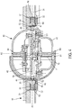
figure 4 représente le tourbillon de lafigure 1 , monté pivotant entre les deux paliers selon un quatrième mode de réalisation de l'invention. - Les
figures 1 à 4 montrent un tourbillon 40 maintenu de part et d'autre par des paliers 20, 30 d'un bâti 10 d'un mouvement d'horlogerie conforme à l'invention. - Le tourbillon 40 illustré comporte deux cages concentriques, une première dite cage externe 41 et une seconde cage dite cage interne 42. La cage interne 42 contient notamment un balancier 50, un spiral, une ancre et une roue d'échappement 51. La cage interne 42 est montée pivotante sur la cage externe 41 selon un axe de rotation A2. Ainsi, le tourbillon 40 comporte un arbre 43 solidaire en rotation de la cage interne 42, et s'étendant en travers de la cage externe 41 selon le deuxième axe de rotation A2. L'arbre 43 comporte deux extrémités, lesdites deux extrémités étant supportées par deux pierres d'horlogerie positionnées sur deux parois opposées de la cage externe 41. Une des extrémités traverse la pierre d'horlogerie qui la supporte et comporte ainsi une zone extrémale qui s'étend à l'extérieur de la cage externe 41.
- Un pignon 60, appelé communément pignon de seconde, est monté sur cette zone extrémale de sorte à être solidaire en rotation de l'arbre 43. Le pignon de seconde 60 comporte une denture 61 en prise avec une denture 71 d'une roue 70, fixe par rapport au bâti 10, communément appelée roue de moyenne fixe. La roue de moyenne fixe 70 est montée concentrique au premier palier 20, et son axe s'étend selon l'axe de rotation A1 de la cage externe 41, ledit axe de rotation A1 étant perpendiculaire à l'axe de rotation A2 de la cage interne 42, voire incliné d'un angle compris entre 30 et 150 degrés par rapport à l'axe de rotation A2 de la cage interne 42.
- Une rotation de la cage interne 42, équivalente à une rotation de l'arbre 43, entraine donc une rotation du pignon de seconde 60, qui entraine une rotation de la cage externe 41 par l'intermédiaire du déplacement du pignon de seconde 60 dans la denture 71 de la roue de moyenne 70.
- La cage externe 41 comporte un premier pivot 44 supporté par une première pierre d'horlogerie 52, et un deuxième pivot 45 supporté par une deuxième pierre d'horlogerie 53. Ces pivots 44, 45, sont positionnés sur l'axe de rotation A1 de la cage externe 41, et solidarisés à des parois opposées de la cage externe 41. Le premier pivot 44, respectivement le deuxième pivot 45, comporte une extrémité 46, respectivement une extrémité 47, traversant la première pierre d'horlogerie 52, respectivement la deuxième pierre d'horlogerie 53, selon l'axe de rotation A2 de la cage interne 42. Les pierres d'horlogerie sont en effet, de manière classique, percées en leur centre de sorte à recevoir l'extrémité d'un pivot.
- Dans le mode de réalisation de la
figure 1 , la première pierre d'horlogerie 52 est elle-même supportée par un premier élément de translation 80 logé dans un premier orifice 21 du premier palier 20. La première pierre d'horlogerie 52 est solidaire du premier élément de translation 80. Quant à la deuxième pierre d'horlogerie 53, elle est supportée par un deuxième élément de translation 90 logé dans un deuxième orifice 31 du deuxième palier 30. La deuxième pierre d'horlogerie 53 est solidaire du deuxième élément de translation 90. - Les orifices 21, 31, et a fortiori les éléments de translation 80, 90 logés dans lesdits orifices 21 31, s'étendent selon l'axe de rotation A1 de la cage externe 41, de part et d'autre de la cage externe 41. Chaque élément de translation 80, 90 comporte donc une première extrémité se trouvant du côté de la cage externe 41, en vis-à-vis de l'un des pivots 44, 45. La première pierre d'horlogerie 52 est maintenue au niveau de l'extrémité du premier élément de translation 80 se trouvant du côté de la cage externe 41, tandis que la deuxième pierre d'horlogerie 53 est maintenue au niveau de l'extrémité du deuxième élément de translation 90 se trouvant du côté de la cage externe 41. Les éléments de translation 80, 90 sont par exemple creux, et les pierres d'horlogerie 52, 53 sont logées dans ces cavités. Naturellement, l'axe des pierres d'horlogerie 52, 53 est confondu avec l'axe de rotation A1 de la cage externe 41, l'axe des éléments de translation 80, 90 et l'axe des pivots 44, 45. On comprend que déplacer les éléments de translation 80, 90 permet de déplacer les pierres d'horlogerie 52, 53, les pierres d'horlogerie étant solidaires des éléments de translation.
- A la
figure 4 est représenté un mode de réalisation alternatif dans lequel les pierres d'horlogerie 52, 53 ne sont pas solidaires des éléments de translation 80, 90, mais solidaires du bâti 10. Plus précisément, la première pierre d'horlogerie 52 est solidaire du premier palier 20, et la deuxième pierre d'horlogerie 53 est solidaire du deuxième palier 30. De plus, le premier élément de translation 80 est en appui contre l'extrémité 46 du premier pivot 44, et le deuxième élément de translation 90 est en appui contre l'extrémité 47 du deuxième pivot 45. On comprend donc que déplacer les éléments de translation 80, 90 permet de déplacer les pivots 44, 45 relativement aux pierres d'horlogerie 52, 53. - Dans le mode de réalisation de la
figure 1 , comme dans celui de lafigure 4 , à son extrémité opposée à celle se trouvant du côté de la cage externe 41, chaque élément de translation 80, 90 comporte des moyens d'actionnement 82, 92. Par coopération entre un outil et les moyens d'actionnement 82, 92, les éléments de translation 80, 90 peuvent être déplacés. Les moyens d'actionnement 82, 92 sont accessibles par l'extérieur via les orifices 21, 31. Les deux éléments de translation 80, 90 peuvent ainsi être déplacés selon l'axe de rotation A1 de la cage externe 41 par l'intermédiaire des moyens d'actionnement 82, 92. - Avantageusement, le premier élément de translation 80 et le deuxième élément de translation 90 sont deux douilles au moins en partie filetées. Dans l'exemple représenté, chacune de ces douilles comporte une portion cylindrique filetée 81, 91 et une portion cylindrique non filetée. La portion filetée 81, 91 est de diamètre inférieur au diamètre de la portion non filetée. Naturellement, puisqu'il reçoit un des éléments de translation, chaque orifice 21, 31 comporte une portion cylindrique taraudée 22, 32 de même diamètre que les portions filetées 81, 91, et une portion cylindrique non taraudée de même diamètre que les portions non filetées. Lorsque les éléments de translation 80, 90 sont des éléments au moins en partie filetés, notamment des douilles, les moyens d'actionnement 82, 92 sont typiquement une fente dans laquelle un tournevis peut être inséré afin d'imposer un mouvement hélicoïdal aux éléments de translation 80, 90.
- Par ailleurs, il est avantageux de doter le mouvement d'un élément de repositionnement. La présence d'un élément de repositionnement est optionnelle. L'élément de repositionnement permet d'assurer que la cage externe reste ou retourne immédiatement dans sa position initiale lorsqu'elle subit un choc.
- Dans un mode de réalisation représenté à la
figure 2 et constituant une amélioration du mode de réalisation de lafigure 1 , l'élément de repositionnement est un aimant 100 logé dans une cavité du deuxième élément de translation 90, et ainsi solidaire du deuxième élément de translation 91. L'aimant 100 est maintenu contre la deuxième pierre d'horlogerie 53, et plus particulièrement du côté de la deuxième pierre d'horlogerie 53 qui est opposé au côté où se trouve la cage externe 41. Comme mentionné précédemment, la deuxième pierre d'horlogerie 53 est percée en son centre de sorte à recevoir l'extrémité 47 du deuxième pivot 45, le perçage s'étendant selon l'axe de rotation A1 de la cage externe 41, entre la face de la deuxième pierre d'horlogerie 53 se trouvant du côté de la cage externe 41, et la face opposée. L'aimant 100 se retrouve donc en contact ou au moins à forte proximité de ladite extrémité 47 du deuxième pivot 45. En choisissant un matériau adapté pour le deuxième pivot 45, par exemple du fer, une force d'attraction est présente entre l'aimant 100 et le deuxième pivot 45. - A la
figure 2 , l'aimant a été représenté en combinaison avec le mode de réalisation de lafigure 1 , mais on comprend qu'il aurait pu être combiné avec le mode de réalisation de lafigure 4 . Dans le mode de réalisation de lafigure 4 , il suffirait de créer une cavité dans le deuxième élément de translation 90, ladite cavité débouchant au niveau de l'extrémité 47 du deuxième pivot 45, et de positionner l'aimant 100 dans cette cavité de sorte que l'aimant soit en contact avec l'extrémité 47. - Si le mouvement subit un choc éloignant la cage externe 41 du deuxième palier 30, l'aimant 100 assure que le deuxième pivot 45, et a fortiori la cage externe 41, reprenne sa position initiale. D'une manière plus générale, l'ajout d'un élément magnétique à proximité ou au contact de l'un des pivots 44, 45 de la cage externe 41 permet de maintenir ou de ramener ce pivot en appui forcé contre la pierre d'horlogerie 52, 53 qui supporte ce pivot 44, 45. Cet appui forcé est garant d'une position invariable de la cage externe 41 et par la même d'un entraxe d'engrenage uniforme entre le pignon 60 et la roue fixe 70. Classiquement, l'entraxe d'engrenage entre le pignon et la roue fixe doit être précis à 0,02 millimètres près et l'ébat d'une cage externe de tourbillon est de l'ordre de 0,05 millimètres au maximum ; on comprend donc qu'il est avantageux de forcer l'appui d'un des pivots contre sa pierre d'horlogerie.
- Dans le mode de réalisation représenté à la
figure 3 , l'élément de repositionnement est un ensemble ressort 101 et piston 102, cette fois installé du côté du premier élément de translation 80. On note que les moyens d'actionnement 82 du premier élément de translation 80 ne sont alors pas accessibles puisque le ressort 101 et le piston 102 bloquent l'accès auxdits moyens d'actionnement 82 et puisque le premier orifice 21 n'est pas traversant. Ainsi, seul le deuxième élément de translation 90 peut être déplacé via l'accès aux éléments d'actionnement 92 par le deuxième orifice 31. - L'axe du piston 102 traverse le premier élément de translation 80 selon l'axe de rotation A1 de la cage externe 41 et appuie contre l'extrémité 46 du premier pivot 44. La tête du piston 102, à l'extérieur du premier élément de translation 80, est en appui contre le ressort 101, qui s'étend lui aussi selon l'axe de rotation A1 de la cage externe 41. Le ressort 101 est logé dans le premier orifice 21 du premier palier 20, ledit premier orifice 21 contenant également le premier élément de translation 80. Comme mentionné précédemment, le premier orifice 21 n'est pas traversant : à son extrémité opposée au piston 102, le ressort 101 peut donc appuyer contre une paroi du premier orifice 21. Lorsque le mouvement subit un choc éloignant la cage externe 41 du deuxième palier 20, le premier pivot 44 exerce une pression contre le piston 102, se répercutant au niveau de la tête du piston sur le ressort 101 et comprimant ledit ressort 101. En cherchant à revenir dans sa position initiale, le ressort 101 déplace le piston 102 en direction de la cage externe 41, l'axe du piston 102 exerçant alors une pression contre le premier pivot 44 qui fait que la cage externe 41 reprend sa position initiale.
- A la
figure 3 , il a été représenté que le premier élément de translation 80 est du type de celui présenté à lafigure 1 , mais naturellement rien n'empêcherait qu'il soit du type de celui présenté à lafigure 4 : il suffirait de réaliser dans le premier élément de translation 80 une cavité le traversant de part et d'autre, pour y insérer l'axe du piston 102. En outre, rien n'empêcherait non plus que le deuxième élément de translation 90 soit du type de celui présenté à lafigure 4 . - Bien entendu, la présente invention ne se limite pas à l'exemple illustré mais est susceptible de diverses variantes et modifications qui apparaîtront à l'homme de l'art. Notamment, le tourbillon pourrait comprendre plus de deux cages, l'invention concernant avant tout la fixation de la cage externe.
-
- 10 bâti
- 20 premier palier
- 21 premier orifice
- 22 taraudage
- 30 deuxième palier
- 31 deuxième orifice
- 32 taraudage
- 40 tourbillon
- 41 cage externe
- 42 cage interne
- 43 arbre
- 44 premier pivot
- 45 deuxième pivot
- 50 balancier
- 51 roue d'échappement
- 52 première pierre d'horlogerie
- 53 deuxième pierre d'horlogerie
- 60 pignon
- 61 denture
- 70 roue fixe
- 71 denture
- 80 premier élément de translation
- 81 filetage
- 82 moyens d'actionnement
- 90 deuxième élément de translation
- 91 filetage
- 92 moyens d'actionnement
- 100 aimant
- 101 ressort
- 102 piston
Claims (10)
- Mouvement d'horlogerie comportant un bâti (10) comprenant un premier palier (20) et un deuxième palier (30), et un tourbillon (40) comprenant deux cages dont une cage dite externe (41),
la cage externe (41) étant montée pivotante sur le bâti (10) entre le premier palier (20) et le deuxième palier (30), le mouvement comprenant en outre deux pierres d'horlogerie (52, 53) supportant deux pivots (44, 45) de la cage externe (41),
caractérisé en ce que le mouvement comporte deux éléments de translation (80, 90) aptes à être déplacés par rapport aux paliers (20, 30) selon l'axe de rotation (A1) de la cage externe (42) en position assemblée de la cage externe (41) sur le bâti (10), de sorte à provoquer un déplacement des pierres d'horlogerie (52, 53) ou un déplacement des pivots (44, 45). - Mouvement d'horlogerie selon la revendication précédente, caractérisé en ce que chaque élément de translation (80, 90) est solidaire d'une des pierres d'horlogerie (52, 53).
- Mouvement d'horlogerie selon la revendication 1, caractérisé en ce que chaque pierre d'horlogerie (52, 53) est solidaire d'un palier (20, 30), et au moins un des éléments de translation (80, 90) est en contact avec une extrémité (46, 47) d'un des pivots (44, 45) ou avec un élément de repositionnement (100, 101, 102) lui-même en contact avec une extrémité (46, 47) d'un des pivots (44, 45).
- Mouvement d'horlogerie selon l'une des revendications précédentes, caractérisé en ce que chaque élément de translation (80, 90) comporte des moyens d'actionnement (82, 92) accessibles par un orifice (21, 31) du palier (10, 20) qui supporte ledit élément de translation (80, 90).
- Mouvement d'horlogerie selon la revendication précédente, caractérisé en ce que les moyens d'actionnement (82, 92) comprennent une fente pour y insérer un outil tel qu'un tournevis.
- Mouvement d'horlogerie selon l'une des revendications 4 ou 5, caractérisé en ce que chaque élément de translation (80, 90) est une douille comprenant un filetage (81, 91) en prise avec un taraudage (22, 32) de l'orifice (21, 32).
- Mouvement d'horlogerie selon l'une des revendications précédentes, caractérisé en ce qu'il comporte en outre un élément de repositionnement (100, 101, 102) logé au moins en partie dans une cavité de l'un des éléments de translation (80, 90), dit premier élément de translation, permettant de maintenir un des pivots (44, 45) dans une position de référence par rapport à la pierre d'horlogerie (52, 53) qui le supporte.
- Mouvement d'horlogerie selon la revendication précédente, caractérisé en ce que l'élément de repositionnement est un aimant (100) logé en partie ou intégralement dans la cavité.
- Mouvement d'horlogerie selon la revendication 7 ou 8, caractérisé en ce que seul l'autre des éléments de translation (80, 90), dit deuxième élément de translation (90), est apte à être déplacé en position assemblée de la cage externe (41) sur le bâti (10), et l'élément de repositionnement comprend un ressort (101) et un piston (102) tous deux logés dans un premier orifice (21) du premier palier (20), l'axe du piston (102) s'étendant en travers du premier élément de translation (80) selon l'axe de rotation (A1) de la cage externe (41), le piston (102) étant en appui d'un côté sur une extrémité du premier pivot (44) et de l'autre côté sur le ressort (101), le deuxième élément de translation (90) étant apte à être déplacé selon l'axe de rotation (A1) de la cage externe (42).
- Mouvement d'horlogerie selon l'une des revendications précédentes, caractérisé en ce que chaque élément de translation (80, 90) est supporté par un palier (10, 20), par un pont ou par une platine du mouvement d'horlogerie.
Applications Claiming Priority (1)
| Application Number | Priority Date | Filing Date | Title |
|---|---|---|---|
| EP17187096 | 2017-08-21 |
Publications (2)
| Publication Number | Publication Date |
|---|---|
| EP3451075A1 true EP3451075A1 (fr) | 2019-03-06 |
| EP3451075B1 EP3451075B1 (fr) | 2020-06-24 |
Family
ID=59677145
Family Applications (1)
| Application Number | Title | Priority Date | Filing Date |
|---|---|---|---|
| EP18184211.3A Active EP3451075B1 (fr) | 2017-08-21 | 2018-07-18 | Mouvement d'horlogerie comportant un tourbillon multiaxial |
Country Status (4)
| Country | Link |
|---|---|
| US (1) | US11048210B2 (fr) |
| EP (1) | EP3451075B1 (fr) |
| JP (1) | JP6549294B2 (fr) |
| CN (1) | CN109426126B (fr) |
Citations (2)
| Publication number | Priority date | Publication date | Assignee | Title |
|---|---|---|---|---|
| CH242661A (fr) * | 1945-09-03 | 1946-05-31 | Surdez Arthur | Palier pour axe de mouvement de montre. |
| DE112012000574T5 (de) * | 2011-05-30 | 2013-11-28 | Tianjin Seagull Watch Co., Ltd. | Zweiachs-Tourbillon für eine mechanische Armbanduhr |
Family Cites Families (12)
| Publication number | Priority date | Publication date | Assignee | Title |
|---|---|---|---|---|
| DE10160287A1 (de) * | 2001-12-07 | 2003-06-26 | Lange Uhren Gmbh | Tourbillon |
| CH697459B1 (fr) * | 2003-04-03 | 2008-10-31 | Franck Mueller Watchland S A | Tourbillon bi-axial pour mouvement horloger, notamment pour montre-bracelet. |
| CH699838B1 (fr) * | 2004-03-09 | 2010-05-14 | Franck Muller Watchland Sa | Tourbillon tri-axial pour pièce d'horlogerie, notamment montre-bracelet. |
| DE602005009316D1 (de) * | 2005-01-28 | 2008-10-09 | Richemont Int Sa | Uhr mit Tourbillon |
| CN201035332Y (zh) * | 2007-05-17 | 2008-03-12 | 李晨光 | 可调陀飞轮机构手表机芯 |
| CN101846961B (zh) * | 2009-03-26 | 2012-01-04 | 天津海鸥表业集团有限公司 | 一种带有两个陀飞轮的机械手表 |
| CH705244B1 (fr) * | 2011-07-07 | 2016-06-30 | Gfpi S A | Pièce d'horlogerie. |
| WO2013044972A1 (fr) * | 2011-09-29 | 2013-04-04 | Télôs Watch SA | Mouvement horloger comprenant un tourbillon |
| CH705836B1 (fr) * | 2011-12-02 | 2016-01-15 | Lvmh Swiss Mft Sa | Pièce d'horlogerie. |
| EP3029530B1 (fr) * | 2014-12-03 | 2019-08-14 | Nivarox-FAR S.A. | Mécanisme de tourbillon |
| US9568887B2 (en) * | 2015-03-09 | 2017-02-14 | Seiko Instruments Inc. | Operation stabilizing mechanism, movement, and mechanical timepiece |
| JP1599863S (fr) * | 2017-03-09 | 2018-03-19 |
-
2018
- 2018-07-18 EP EP18184211.3A patent/EP3451075B1/fr active Active
- 2018-08-03 US US16/053,991 patent/US11048210B2/en active Active
- 2018-08-09 JP JP2018149947A patent/JP6549294B2/ja active Active
- 2018-08-21 CN CN201810952472.5A patent/CN109426126B/zh active Active
Patent Citations (2)
| Publication number | Priority date | Publication date | Assignee | Title |
|---|---|---|---|---|
| CH242661A (fr) * | 1945-09-03 | 1946-05-31 | Surdez Arthur | Palier pour axe de mouvement de montre. |
| DE112012000574T5 (de) * | 2011-05-30 | 2013-11-28 | Tianjin Seagull Watch Co., Ltd. | Zweiachs-Tourbillon für eine mechanische Armbanduhr |
Also Published As
| Publication number | Publication date |
|---|---|
| JP2019035747A (ja) | 2019-03-07 |
| US20190056695A1 (en) | 2019-02-21 |
| CN109426126A (zh) | 2019-03-05 |
| EP3451075B1 (fr) | 2020-06-24 |
| US11048210B2 (en) | 2021-06-29 |
| JP6549294B2 (ja) | 2019-07-24 |
| CN109426126B (zh) | 2020-10-27 |
Similar Documents
| Publication | Publication Date | Title |
|---|---|---|
| EP2080066B1 (fr) | Piece d'horlogerie | |
| EP2233988B1 (fr) | Mouvement horloger à tourbillon muni d'un dispositif de protection contre les chocs | |
| EP1837719B1 (fr) | Balancier pour mouvement d'horlogerie | |
| EP2290477A1 (fr) | Ensemble de fixation de l'extrémite péripherique du spiral d'un dispositif à balancier-spiral pour pièce d'horlogerie | |
| EP3172626A1 (fr) | Pivot à lame | |
| EP3451075B1 (fr) | Mouvement d'horlogerie comportant un tourbillon multiaxial | |
| CH705464A2 (fr) | Virole de fixation d'un spiral d'horlogerie. | |
| CH714073A2 (fr) | Mouvement d'horlogerie comportant un tourbillon multiaxial. | |
| EP1574918B1 (fr) | Mécanisme de positionnement et de blocage de moyens d'affichage dans une ouverture du cadran d'un appareil électronique portable | |
| CH706846B1 (fr) | Virole pour un organe régulateur balancier-spiral. | |
| EP0814389B1 (fr) | Mouvement d'horlogerie comportant un tube de guidage entre une platine et un pont | |
| EP1923754B1 (fr) | Mouvement d'horlogerie équipé d'un module d'affichage | |
| EP1708052B1 (fr) | Mouvement d'horlogerie | |
| EP3037895B1 (fr) | Porte-piton demontable | |
| EP2869139B1 (fr) | Mécanisme de tourbillon | |
| CH702994A2 (fr) | Piece d'horlogerie. | |
| CH707226B1 (fr) | Mouvement horloger pourvu d'un balancier monté pivotant à l'aide d'un roulement à billes ou à galets. | |
| EP4109181A1 (fr) | Cadran, montre comprenant un tel cadran et procédé d'installation d'un tel cadran dans une montre | |
| EP1434113B1 (fr) | Mécanisme de tourbillon et pièce d'horlogerie munie d'un tel mécanisme | |
| CH716149A1 (fr) | Mouvement d'horlogerie comprenant au moins un timbre. | |
| EP0012460A1 (fr) | Stator monobloc pour moteur pas à pas d'horlogerie | |
| CH716864A2 (fr) | Tourbillon pour mouvement horloger. | |
| CH697211A5 (fr) | Mécanisme de positionnement et de blocage de moyens d'affichage dans un appareil électronique portable. | |
| CH720809A2 (fr) | Cage de tourbillon | |
| EP4462193A1 (fr) | Mouvement horloger mécanique comprenant un mobile portant un organe d' affichage et muni d'un dispositif de freinage |
Legal Events
| Date | Code | Title | Description |
|---|---|---|---|
| PUAI | Public reference made under article 153(3) epc to a published international application that has entered the european phase |
Free format text: ORIGINAL CODE: 0009012 |
|
| STAA | Information on the status of an ep patent application or granted ep patent |
Free format text: STATUS: THE APPLICATION HAS BEEN PUBLISHED |
|
| AK | Designated contracting states |
Kind code of ref document: A1 Designated state(s): AL AT BE BG CH CY CZ DE DK EE ES FI FR GB GR HR HU IE IS IT LI LT LU LV MC MK MT NL NO PL PT RO RS SE SI SK SM TR |
|
| AX | Request for extension of the european patent |
Extension state: BA ME |
|
| STAA | Information on the status of an ep patent application or granted ep patent |
Free format text: STATUS: REQUEST FOR EXAMINATION WAS MADE |
|
| 17P | Request for examination filed |
Effective date: 20190906 |
|
| RBV | Designated contracting states (corrected) |
Designated state(s): AL AT BE BG CH CY CZ DE DK EE ES FI FR GB GR HR HU IE IS IT LI LT LU LV MC MK MT NL NO PL PT RO RS SE SI SK SM TR |
|
| GRAP | Despatch of communication of intention to grant a patent |
Free format text: ORIGINAL CODE: EPIDOSNIGR1 |
|
| STAA | Information on the status of an ep patent application or granted ep patent |
Free format text: STATUS: GRANT OF PATENT IS INTENDED |
|
| INTG | Intention to grant announced |
Effective date: 20200220 |
|
| GRAS | Grant fee paid |
Free format text: ORIGINAL CODE: EPIDOSNIGR3 |
|
| GRAA | (expected) grant |
Free format text: ORIGINAL CODE: 0009210 |
|
| STAA | Information on the status of an ep patent application or granted ep patent |
Free format text: STATUS: THE PATENT HAS BEEN GRANTED |
|
| AK | Designated contracting states |
Kind code of ref document: B1 Designated state(s): AL AT BE BG CH CY CZ DE DK EE ES FI FR GB GR HR HU IE IS IT LI LT LU LV MC MK MT NL NO PL PT RO RS SE SI SK SM TR |
|
| REG | Reference to a national code |
Ref country code: GB Ref legal event code: FG4D Free format text: NOT ENGLISH |
|
| REG | Reference to a national code |
Ref country code: CH Ref legal event code: EP Ref country code: CH Ref legal event code: NV Representative=s name: ICB INGENIEURS CONSEILS EN BREVETS SA, CH |
|
| REG | Reference to a national code |
Ref country code: AT Ref legal event code: REF Ref document number: 1284507 Country of ref document: AT Kind code of ref document: T Effective date: 20200715 |
|
| REG | Reference to a national code |
Ref country code: DE Ref legal event code: R096 Ref document number: 602018005500 Country of ref document: DE |
|
| REG | Reference to a national code |
Ref country code: IE Ref legal event code: FG4D Free format text: LANGUAGE OF EP DOCUMENT: FRENCH |
|
| PG25 | Lapsed in a contracting state [announced via postgrant information from national office to epo] |
Ref country code: NO Free format text: LAPSE BECAUSE OF FAILURE TO SUBMIT A TRANSLATION OF THE DESCRIPTION OR TO PAY THE FEE WITHIN THE PRESCRIBED TIME-LIMIT Effective date: 20200924 Ref country code: FI Free format text: LAPSE BECAUSE OF FAILURE TO SUBMIT A TRANSLATION OF THE DESCRIPTION OR TO PAY THE FEE WITHIN THE PRESCRIBED TIME-LIMIT Effective date: 20200624 Ref country code: LT Free format text: LAPSE BECAUSE OF FAILURE TO SUBMIT A TRANSLATION OF THE DESCRIPTION OR TO PAY THE FEE WITHIN THE PRESCRIBED TIME-LIMIT Effective date: 20200624 Ref country code: SE Free format text: LAPSE BECAUSE OF FAILURE TO SUBMIT A TRANSLATION OF THE DESCRIPTION OR TO PAY THE FEE WITHIN THE PRESCRIBED TIME-LIMIT Effective date: 20200624 Ref country code: GR Free format text: LAPSE BECAUSE OF FAILURE TO SUBMIT A TRANSLATION OF THE DESCRIPTION OR TO PAY THE FEE WITHIN THE PRESCRIBED TIME-LIMIT Effective date: 20200925 |
|
| REG | Reference to a national code |
Ref country code: LT Ref legal event code: MG4D |
|
| PG25 | Lapsed in a contracting state [announced via postgrant information from national office to epo] |
Ref country code: RS Free format text: LAPSE BECAUSE OF FAILURE TO SUBMIT A TRANSLATION OF THE DESCRIPTION OR TO PAY THE FEE WITHIN THE PRESCRIBED TIME-LIMIT Effective date: 20200624 Ref country code: BG Free format text: LAPSE BECAUSE OF FAILURE TO SUBMIT A TRANSLATION OF THE DESCRIPTION OR TO PAY THE FEE WITHIN THE PRESCRIBED TIME-LIMIT Effective date: 20200924 Ref country code: LV Free format text: LAPSE BECAUSE OF FAILURE TO SUBMIT A TRANSLATION OF THE DESCRIPTION OR TO PAY THE FEE WITHIN THE PRESCRIBED TIME-LIMIT Effective date: 20200624 Ref country code: HR Free format text: LAPSE BECAUSE OF FAILURE TO SUBMIT A TRANSLATION OF THE DESCRIPTION OR TO PAY THE FEE WITHIN THE PRESCRIBED TIME-LIMIT Effective date: 20200624 |
|
| REG | Reference to a national code |
Ref country code: NL Ref legal event code: MP Effective date: 20200624 |
|
| REG | Reference to a national code |
Ref country code: AT Ref legal event code: MK05 Ref document number: 1284507 Country of ref document: AT Kind code of ref document: T Effective date: 20200624 |
|
| PG25 | Lapsed in a contracting state [announced via postgrant information from national office to epo] |
Ref country code: AL Free format text: LAPSE BECAUSE OF FAILURE TO SUBMIT A TRANSLATION OF THE DESCRIPTION OR TO PAY THE FEE WITHIN THE PRESCRIBED TIME-LIMIT Effective date: 20200624 Ref country code: NL Free format text: LAPSE BECAUSE OF FAILURE TO SUBMIT A TRANSLATION OF THE DESCRIPTION OR TO PAY THE FEE WITHIN THE PRESCRIBED TIME-LIMIT Effective date: 20200624 |
|
| PG25 | Lapsed in a contracting state [announced via postgrant information from national office to epo] |
Ref country code: PT Free format text: LAPSE BECAUSE OF FAILURE TO SUBMIT A TRANSLATION OF THE DESCRIPTION OR TO PAY THE FEE WITHIN THE PRESCRIBED TIME-LIMIT Effective date: 20201026 Ref country code: ES Free format text: LAPSE BECAUSE OF FAILURE TO SUBMIT A TRANSLATION OF THE DESCRIPTION OR TO PAY THE FEE WITHIN THE PRESCRIBED TIME-LIMIT Effective date: 20200624 Ref country code: RO Free format text: LAPSE BECAUSE OF FAILURE TO SUBMIT A TRANSLATION OF THE DESCRIPTION OR TO PAY THE FEE WITHIN THE PRESCRIBED TIME-LIMIT Effective date: 20200624 Ref country code: AT Free format text: LAPSE BECAUSE OF FAILURE TO SUBMIT A TRANSLATION OF THE DESCRIPTION OR TO PAY THE FEE WITHIN THE PRESCRIBED TIME-LIMIT Effective date: 20200624 Ref country code: CZ Free format text: LAPSE BECAUSE OF FAILURE TO SUBMIT A TRANSLATION OF THE DESCRIPTION OR TO PAY THE FEE WITHIN THE PRESCRIBED TIME-LIMIT Effective date: 20200624 Ref country code: IT Free format text: LAPSE BECAUSE OF FAILURE TO SUBMIT A TRANSLATION OF THE DESCRIPTION OR TO PAY THE FEE WITHIN THE PRESCRIBED TIME-LIMIT Effective date: 20200624 Ref country code: SM Free format text: LAPSE BECAUSE OF FAILURE TO SUBMIT A TRANSLATION OF THE DESCRIPTION OR TO PAY THE FEE WITHIN THE PRESCRIBED TIME-LIMIT Effective date: 20200624 Ref country code: EE Free format text: LAPSE BECAUSE OF FAILURE TO SUBMIT A TRANSLATION OF THE DESCRIPTION OR TO PAY THE FEE WITHIN THE PRESCRIBED TIME-LIMIT Effective date: 20200624 |
|
| PG25 | Lapsed in a contracting state [announced via postgrant information from national office to epo] |
Ref country code: SK Free format text: LAPSE BECAUSE OF FAILURE TO SUBMIT A TRANSLATION OF THE DESCRIPTION OR TO PAY THE FEE WITHIN THE PRESCRIBED TIME-LIMIT Effective date: 20200624 Ref country code: PL Free format text: LAPSE BECAUSE OF FAILURE TO SUBMIT A TRANSLATION OF THE DESCRIPTION OR TO PAY THE FEE WITHIN THE PRESCRIBED TIME-LIMIT Effective date: 20200624 Ref country code: IS Free format text: LAPSE BECAUSE OF FAILURE TO SUBMIT A TRANSLATION OF THE DESCRIPTION OR TO PAY THE FEE WITHIN THE PRESCRIBED TIME-LIMIT Effective date: 20201024 |
|
| REG | Reference to a national code |
Ref country code: DE Ref legal event code: R097 Ref document number: 602018005500 Country of ref document: DE |
|
| PG25 | Lapsed in a contracting state [announced via postgrant information from national office to epo] |
Ref country code: MC Free format text: LAPSE BECAUSE OF FAILURE TO SUBMIT A TRANSLATION OF THE DESCRIPTION OR TO PAY THE FEE WITHIN THE PRESCRIBED TIME-LIMIT Effective date: 20200624 |
|
| REG | Reference to a national code |
Ref country code: BE Ref legal event code: MM Effective date: 20200731 |
|
| PG25 | Lapsed in a contracting state [announced via postgrant information from national office to epo] |
Ref country code: LU Free format text: LAPSE BECAUSE OF NON-PAYMENT OF DUE FEES Effective date: 20200718 Ref country code: DK Free format text: LAPSE BECAUSE OF FAILURE TO SUBMIT A TRANSLATION OF THE DESCRIPTION OR TO PAY THE FEE WITHIN THE PRESCRIBED TIME-LIMIT Effective date: 20200624 |
|
| PLBE | No opposition filed within time limit |
Free format text: ORIGINAL CODE: 0009261 |
|
| STAA | Information on the status of an ep patent application or granted ep patent |
Free format text: STATUS: NO OPPOSITION FILED WITHIN TIME LIMIT |
|
| PG25 | Lapsed in a contracting state [announced via postgrant information from national office to epo] |
Ref country code: BE Free format text: LAPSE BECAUSE OF NON-PAYMENT OF DUE FEES Effective date: 20200731 |
|
| 26N | No opposition filed |
Effective date: 20210325 |
|
| PG25 | Lapsed in a contracting state [announced via postgrant information from national office to epo] |
Ref country code: SI Free format text: LAPSE BECAUSE OF FAILURE TO SUBMIT A TRANSLATION OF THE DESCRIPTION OR TO PAY THE FEE WITHIN THE PRESCRIBED TIME-LIMIT Effective date: 20200624 Ref country code: IE Free format text: LAPSE BECAUSE OF NON-PAYMENT OF DUE FEES Effective date: 20200718 |
|
| PG25 | Lapsed in a contracting state [announced via postgrant information from national office to epo] |
Ref country code: TR Free format text: LAPSE BECAUSE OF FAILURE TO SUBMIT A TRANSLATION OF THE DESCRIPTION OR TO PAY THE FEE WITHIN THE PRESCRIBED TIME-LIMIT Effective date: 20200624 Ref country code: MT Free format text: LAPSE BECAUSE OF FAILURE TO SUBMIT A TRANSLATION OF THE DESCRIPTION OR TO PAY THE FEE WITHIN THE PRESCRIBED TIME-LIMIT Effective date: 20200624 Ref country code: CY Free format text: LAPSE BECAUSE OF FAILURE TO SUBMIT A TRANSLATION OF THE DESCRIPTION OR TO PAY THE FEE WITHIN THE PRESCRIBED TIME-LIMIT Effective date: 20200624 |
|
| PG25 | Lapsed in a contracting state [announced via postgrant information from national office to epo] |
Ref country code: MK Free format text: LAPSE BECAUSE OF FAILURE TO SUBMIT A TRANSLATION OF THE DESCRIPTION OR TO PAY THE FEE WITHIN THE PRESCRIBED TIME-LIMIT Effective date: 20200624 |
|
| P01 | Opt-out of the competence of the unified patent court (upc) registered |
Effective date: 20230611 |
|
| PGFP | Annual fee paid to national office [announced via postgrant information from national office to epo] |
Ref country code: GB Payment date: 20250619 Year of fee payment: 8 |
|
| PGFP | Annual fee paid to national office [announced via postgrant information from national office to epo] |
Ref country code: FR Payment date: 20250620 Year of fee payment: 8 |
|
| PGFP | Annual fee paid to national office [announced via postgrant information from national office to epo] |
Ref country code: DE Payment date: 20250620 Year of fee payment: 8 |
|
| PGFP | Annual fee paid to national office [announced via postgrant information from national office to epo] |
Ref country code: CH Payment date: 20250801 Year of fee payment: 8 |