EP3450884A1 - Refrigeration cycle apparatus - Google Patents
Refrigeration cycle apparatus Download PDFInfo
- Publication number
- EP3450884A1 EP3450884A1 EP16900434.8A EP16900434A EP3450884A1 EP 3450884 A1 EP3450884 A1 EP 3450884A1 EP 16900434 A EP16900434 A EP 16900434A EP 3450884 A1 EP3450884 A1 EP 3450884A1
- Authority
- EP
- European Patent Office
- Prior art keywords
- air
- refrigerant
- sending fan
- manipulation
- indoor
- Prior art date
- Legal status (The legal status is an assumption and is not a legal conclusion. Google has not performed a legal analysis and makes no representation as to the accuracy of the status listed.)
- Granted
Links
Images


Classifications
-
- F—MECHANICAL ENGINEERING; LIGHTING; HEATING; WEAPONS; BLASTING
- F24—HEATING; RANGES; VENTILATING
- F24F—AIR-CONDITIONING; AIR-HUMIDIFICATION; VENTILATION; USE OF AIR CURRENTS FOR SCREENING
- F24F1/00—Room units for air-conditioning, e.g. separate or self-contained units or units receiving primary air from a central station
- F24F1/0003—Room units for air-conditioning, e.g. separate or self-contained units or units receiving primary air from a central station characterised by a split arrangement, wherein parts of the air-conditioning system, e.g. evaporator and condenser, are in separately located units
-
- F—MECHANICAL ENGINEERING; LIGHTING; HEATING; WEAPONS; BLASTING
- F24—HEATING; RANGES; VENTILATING
- F24F—AIR-CONDITIONING; AIR-HUMIDIFICATION; VENTILATION; USE OF AIR CURRENTS FOR SCREENING
- F24F1/00—Room units for air-conditioning, e.g. separate or self-contained units or units receiving primary air from a central station
- F24F1/0007—Indoor units, e.g. fan coil units
- F24F1/0043—Indoor units, e.g. fan coil units characterised by mounting arrangements
- F24F1/005—Indoor units, e.g. fan coil units characterised by mounting arrangements mounted on the floor; standing on the floor
-
- F—MECHANICAL ENGINEERING; LIGHTING; HEATING; WEAPONS; BLASTING
- F24—HEATING; RANGES; VENTILATING
- F24F—AIR-CONDITIONING; AIR-HUMIDIFICATION; VENTILATION; USE OF AIR CURRENTS FOR SCREENING
- F24F11/00—Control or safety arrangements
- F24F11/30—Control or safety arrangements for purposes related to the operation of the system, e.g. for safety or monitoring
- F24F11/32—Responding to malfunctions or emergencies
- F24F11/36—Responding to malfunctions or emergencies to leakage of heat-exchange fluid
-
- F—MECHANICAL ENGINEERING; LIGHTING; HEATING; WEAPONS; BLASTING
- F24—HEATING; RANGES; VENTILATING
- F24F—AIR-CONDITIONING; AIR-HUMIDIFICATION; VENTILATION; USE OF AIR CURRENTS FOR SCREENING
- F24F11/00—Control or safety arrangements
- F24F11/50—Control or safety arrangements characterised by user interfaces or communication
-
- F—MECHANICAL ENGINEERING; LIGHTING; HEATING; WEAPONS; BLASTING
- F24—HEATING; RANGES; VENTILATING
- F24F—AIR-CONDITIONING; AIR-HUMIDIFICATION; VENTILATION; USE OF AIR CURRENTS FOR SCREENING
- F24F11/00—Control or safety arrangements
- F24F11/50—Control or safety arrangements characterised by user interfaces or communication
- F24F11/61—Control or safety arrangements characterised by user interfaces or communication using timers
-
- F—MECHANICAL ENGINEERING; LIGHTING; HEATING; WEAPONS; BLASTING
- F24—HEATING; RANGES; VENTILATING
- F24F—AIR-CONDITIONING; AIR-HUMIDIFICATION; VENTILATION; USE OF AIR CURRENTS FOR SCREENING
- F24F11/00—Control or safety arrangements
- F24F11/62—Control or safety arrangements characterised by the type of control or by internal processing, e.g. using fuzzy logic, adaptive control or estimation of values
- F24F11/63—Electronic processing
- F24F11/65—Electronic processing for selecting an operating mode
-
- F—MECHANICAL ENGINEERING; LIGHTING; HEATING; WEAPONS; BLASTING
- F24—HEATING; RANGES; VENTILATING
- F24F—AIR-CONDITIONING; AIR-HUMIDIFICATION; VENTILATION; USE OF AIR CURRENTS FOR SCREENING
- F24F11/00—Control or safety arrangements
- F24F11/70—Control systems characterised by their outputs; Constructional details thereof
- F24F11/72—Control systems characterised by their outputs; Constructional details thereof for controlling the supply of treated air, e.g. its pressure
-
- F—MECHANICAL ENGINEERING; LIGHTING; HEATING; WEAPONS; BLASTING
- F24—HEATING; RANGES; VENTILATING
- F24F—AIR-CONDITIONING; AIR-HUMIDIFICATION; VENTILATION; USE OF AIR CURRENTS FOR SCREENING
- F24F11/00—Control or safety arrangements
- F24F11/70—Control systems characterised by their outputs; Constructional details thereof
- F24F11/72—Control systems characterised by their outputs; Constructional details thereof for controlling the supply of treated air, e.g. its pressure
- F24F11/74—Control systems characterised by their outputs; Constructional details thereof for controlling the supply of treated air, e.g. its pressure for controlling air flow rate or air velocity
-
- F—MECHANICAL ENGINEERING; LIGHTING; HEATING; WEAPONS; BLASTING
- F24—HEATING; RANGES; VENTILATING
- F24F—AIR-CONDITIONING; AIR-HUMIDIFICATION; VENTILATION; USE OF AIR CURRENTS FOR SCREENING
- F24F11/00—Control or safety arrangements
- F24F11/89—Arrangement or mounting of control or safety devices
-
- F—MECHANICAL ENGINEERING; LIGHTING; HEATING; WEAPONS; BLASTING
- F25—REFRIGERATION OR COOLING; COMBINED HEATING AND REFRIGERATION SYSTEMS; HEAT PUMP SYSTEMS; MANUFACTURE OR STORAGE OF ICE; LIQUEFACTION SOLIDIFICATION OF GASES
- F25B—REFRIGERATION MACHINES, PLANTS OR SYSTEMS; COMBINED HEATING AND REFRIGERATION SYSTEMS; HEAT PUMP SYSTEMS
- F25B13/00—Compression machines, plants or systems, with reversible cycle
-
- F—MECHANICAL ENGINEERING; LIGHTING; HEATING; WEAPONS; BLASTING
- F25—REFRIGERATION OR COOLING; COMBINED HEATING AND REFRIGERATION SYSTEMS; HEAT PUMP SYSTEMS; MANUFACTURE OR STORAGE OF ICE; LIQUEFACTION SOLIDIFICATION OF GASES
- F25B—REFRIGERATION MACHINES, PLANTS OR SYSTEMS; COMBINED HEATING AND REFRIGERATION SYSTEMS; HEAT PUMP SYSTEMS
- F25B49/00—Arrangement or mounting of control or safety devices
- F25B49/02—Arrangement or mounting of control or safety devices for compression type machines, plants or systems
-
- F—MECHANICAL ENGINEERING; LIGHTING; HEATING; WEAPONS; BLASTING
- F25—REFRIGERATION OR COOLING; COMBINED HEATING AND REFRIGERATION SYSTEMS; HEAT PUMP SYSTEMS; MANUFACTURE OR STORAGE OF ICE; LIQUEFACTION SOLIDIFICATION OF GASES
- F25B—REFRIGERATION MACHINES, PLANTS OR SYSTEMS; COMBINED HEATING AND REFRIGERATION SYSTEMS; HEAT PUMP SYSTEMS
- F25B9/00—Compression machines, plants or systems, in which the refrigerant is air or other gas of low boiling point
- F25B9/002—Compression machines, plants or systems, in which the refrigerant is air or other gas of low boiling point characterised by the refrigerant
-
- F—MECHANICAL ENGINEERING; LIGHTING; HEATING; WEAPONS; BLASTING
- F24—HEATING; RANGES; VENTILATING
- F24F—AIR-CONDITIONING; AIR-HUMIDIFICATION; VENTILATION; USE OF AIR CURRENTS FOR SCREENING
- F24F2221/00—Details or features not otherwise provided for
- F24F2221/54—Heating and cooling, simultaneously or alternatively
-
- F—MECHANICAL ENGINEERING; LIGHTING; HEATING; WEAPONS; BLASTING
- F25—REFRIGERATION OR COOLING; COMBINED HEATING AND REFRIGERATION SYSTEMS; HEAT PUMP SYSTEMS; MANUFACTURE OR STORAGE OF ICE; LIQUEFACTION SOLIDIFICATION OF GASES
- F25B—REFRIGERATION MACHINES, PLANTS OR SYSTEMS; COMBINED HEATING AND REFRIGERATION SYSTEMS; HEAT PUMP SYSTEMS
- F25B2313/00—Compression machines, plants or systems with reversible cycle not otherwise provided for
- F25B2313/027—Compression machines, plants or systems with reversible cycle not otherwise provided for characterised by the reversing means
- F25B2313/02741—Compression machines, plants or systems with reversible cycle not otherwise provided for characterised by the reversing means using one four-way valve
-
- F—MECHANICAL ENGINEERING; LIGHTING; HEATING; WEAPONS; BLASTING
- F25—REFRIGERATION OR COOLING; COMBINED HEATING AND REFRIGERATION SYSTEMS; HEAT PUMP SYSTEMS; MANUFACTURE OR STORAGE OF ICE; LIQUEFACTION SOLIDIFICATION OF GASES
- F25B—REFRIGERATION MACHINES, PLANTS OR SYSTEMS; COMBINED HEATING AND REFRIGERATION SYSTEMS; HEAT PUMP SYSTEMS
- F25B2313/00—Compression machines, plants or systems with reversible cycle not otherwise provided for
- F25B2313/029—Control issues
- F25B2313/0293—Control issues related to the indoor fan, e.g. controlling speed
-
- F—MECHANICAL ENGINEERING; LIGHTING; HEATING; WEAPONS; BLASTING
- F25—REFRIGERATION OR COOLING; COMBINED HEATING AND REFRIGERATION SYSTEMS; HEAT PUMP SYSTEMS; MANUFACTURE OR STORAGE OF ICE; LIQUEFACTION SOLIDIFICATION OF GASES
- F25B—REFRIGERATION MACHINES, PLANTS OR SYSTEMS; COMBINED HEATING AND REFRIGERATION SYSTEMS; HEAT PUMP SYSTEMS
- F25B2500/00—Problems to be solved
- F25B2500/22—Preventing, detecting or repairing leaks of refrigeration fluids
- F25B2500/222—Detecting refrigerant leaks
-
- F—MECHANICAL ENGINEERING; LIGHTING; HEATING; WEAPONS; BLASTING
- F25—REFRIGERATION OR COOLING; COMBINED HEATING AND REFRIGERATION SYSTEMS; HEAT PUMP SYSTEMS; MANUFACTURE OR STORAGE OF ICE; LIQUEFACTION SOLIDIFICATION OF GASES
- F25B—REFRIGERATION MACHINES, PLANTS OR SYSTEMS; COMBINED HEATING AND REFRIGERATION SYSTEMS; HEAT PUMP SYSTEMS
- F25B2600/00—Control issues
- F25B2600/01—Timing
-
- F—MECHANICAL ENGINEERING; LIGHTING; HEATING; WEAPONS; BLASTING
- F25—REFRIGERATION OR COOLING; COMBINED HEATING AND REFRIGERATION SYSTEMS; HEAT PUMP SYSTEMS; MANUFACTURE OR STORAGE OF ICE; LIQUEFACTION SOLIDIFICATION OF GASES
- F25B—REFRIGERATION MACHINES, PLANTS OR SYSTEMS; COMBINED HEATING AND REFRIGERATION SYSTEMS; HEAT PUMP SYSTEMS
- F25B2600/00—Control issues
- F25B2600/25—Control of valves
- F25B2600/2513—Expansion valves
-
- F—MECHANICAL ENGINEERING; LIGHTING; HEATING; WEAPONS; BLASTING
- F25—REFRIGERATION OR COOLING; COMBINED HEATING AND REFRIGERATION SYSTEMS; HEAT PUMP SYSTEMS; MANUFACTURE OR STORAGE OF ICE; LIQUEFACTION SOLIDIFICATION OF GASES
- F25B—REFRIGERATION MACHINES, PLANTS OR SYSTEMS; COMBINED HEATING AND REFRIGERATION SYSTEMS; HEAT PUMP SYSTEMS
- F25B2700/00—Sensing or detecting of parameters; Sensors therefor
- F25B2700/19—Pressures
- F25B2700/193—Pressures of the compressor
- F25B2700/1931—Discharge pressures
Definitions
- the present invention relates to a refrigeration cycle apparatus including an air-sending fan.
- Patent Literature 1 there is described an indoor unit of an air-conditioning apparatus.
- This indoor unit includes a refrigerant detection unit configured to detect leakage of refrigerant, a controller configured to perform, when the refrigerant detection unit detects leakage of the refrigerant, control for causing an air-sending fan to forcedly rotate and causing a warning device to issue a warning, and an operation device for inputting, to the controller, a stop command for the air-sending fan and the warning device based on a manual operation of the operation unit.
- sound output (buzzer) output from the warning device can be stopped by manipulations on the operation device performed by a user even before a service person arrives and performs inspection and repair. Therefore, a cause of noise that bothers its vicinities can be eliminated, with the result that dissatisfaction of the user can be get rid of.
- Patent Literature 1 Japanese Patent No. 5812081
- the air-conditioning apparatus includes three operation modes, namely, a cooling mode, a heating mode, and an air-sending mode, and hence it is possible to perform the operation of the air-sending fan in the air-sending mode by manipulating a remote controller serving as the operation device.
- the operation of the air-sending fan in the air-sending mode can be disadvantageously stopped through a manipulation of the remote controller performed by the user or another person.
- the user or another person who does not know the cause of leakage and how the inspection and repair was performed may stop the operation of the air-sending fan through the manipulation of the remote controller on his or her own judgment.
- there may be a place at which a concentration of refrigerant that has leaked is increased locally in an indoor space.
- the present invention has been made in view of the above-mentioned problems, and it is an object of the present invention to provide a refrigeration cycle apparatus capable of inhibiting a refrigerant concentration of refrigerant that has leaked from increasing locally.
- a refrigeration cycle apparatus including: a refrigerant circuit configured to circulate refrigerant; an indoor unit configured to accommodate at least a load-side heat exchanger of the refrigerant circuit; a controller configured to control the indoor unit; and an operation unit configured to receive a manipulation on the indoor unit, the indoor unit including: a refrigerant detection unit; and an air-sending fan, the controller being configured to cause a first operation mode and a second operation mode to be executed as operation modes of the air-sending fan, the first operation mode being an operation mode in which an operation of the air-sending fan is started based on a first operation performed on the operation unit and the air-sending fan is stopped based on a second operation performed on the operation unit, the second operation mode being an operation mode in which the operation of the air-sending fan is started when refrigerant is detected by the refrigerant detection unit, the air-sending fan is prevented from being stopped based on the second manipulation, the air-sending fan is stopped
- the operation of the air-sending fan is started when refrigerant is detected by the refrigerant detection unit, the air-sending fan is stopped based on the third operation different from the second operation, and the operation of the air-sending fan is restarted based on the fourth manipulation different from the first manipulation. In this manner, it is possible to inhibit the refrigerant concentration of the refrigerant that has leaked from increasing locally.
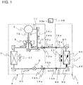
- FIG. 1 is a refrigerant circuit diagram for illustrating a schematic configuration of the air-conditioning apparatus in the embodiment of the present invention.
- each component may have a dimensional relationship, a shape, and the like that are different from actual ones.
- the air-conditioning apparatus includes a refrigerant circuit 40 configured to circulate refrigerant.
- the refrigerant circuit 40 includes a compressor 3, a refrigerant flow switching device 4, a heat source-side heat exchanger 5 (for example, outdoor heat exchanger), a pressure reducing device 6, and a load-side heat exchanger 7 (for example, indoor heat exchanger), which are sequentially connected to form a circuit through refrigerant pipes.
- the air-conditioning apparatus includes an outdoor unit 2, which is installed, for example, outdoors as a heat source unit.
- the air-conditioning apparatus includes an indoor unit 1, which is installed, for example, indoors as a load unit.
- the indoor unit 1 and the outdoor unit 2 are connected to each other through extension pipes 10a and 10b forming parts of the refrigerant pipes.
- Examples of a refrigerant to be used as the refrigerant to be circulated by the refrigerant circuit 40 include a slightly flammable refrigerant such as HFO-1234yf or HFO-1234ze and a strongly flammable refrigerant such as R290 or R1270.
- a slightly flammable refrigerant such as HFO-1234yf or HFO-1234ze
- a strongly flammable refrigerant such as R290 or R1270.
- Each of those refrigerants may be used as a single-component refrigerant, or may be used as a mixed refrigerant obtained by mixing two or more kinds of the refrigerants with each other.
- the refrigerant having a flammability equal to or higher than a slightly flammable level (for example, 2L or higher in category of ASHRAE34) is often referred to as "flammable refrigerant".
- a nonflammable refrigerant having a nonflammability for example, 1 in category of ASHRAE34
- R22 or R410A can be used as the refrigerant to be circulated by the refrigerant circuit 40.
- Those refrigerants have a density larger than that of air under an atmospheric pressure (for example, the temperature is room temperature (25 degrees C)).
- the compressor 3 is a fluid machine configured to compress a sucked low-pressure refrigerant and to discharge the low-pressure refrigerant as high-pressure refrigerant.
- the refrigerant flow switching device 4 is configured to switch a flow direction of the refrigerant within the refrigerant circuit 40 between a cooling operation and a heating operation.
- a four-way valve is used as the refrigerant flow switching device 4, for example.
- the heat source-side heat exchanger 5 is a heat exchanger configured to function as a radiator (for example, condenser) in the cooling operation and to function as an evaporator in the heating operation.
- the heat source-side heat exchanger 5 exchanges heat between the refrigerant circulated through an inside of the heat source-side heat exchanger 5 and outdoor air sent by an outdoor air-sending fan 5f to be described later.
- the pressure reducing device 6 is configured to reduce the pressure of the high-pressure refrigerant such that the high-pressure refrigerant becomes the low-pressure refrigerant.
- an electronic expansion valve capable of adjusting its opening degree is used.
- the load-side heat exchanger 7 is a heat exchanger configured to function as an evaporator in the cooling operation and to function as a radiator (for example, condenser) in the heating operation.
- the load-side heat exchanger 7 exchanges heat between the refrigerant circulated through an inside of the load-side heat exchanger 7 and air sent by an indoor air-sending fan 7f to be described later.
- the cooling operation represents an operation for supplying low-temperature and low-pressure refrigerant to the load-side heat exchanger 7
- the heating operation represents an operation for supplying high-temperature and high-pressure refrigerant to the load-side heat exchanger 7.
- the outdoor unit 2 accommodates the compressor 3, the refrigerant flow switching device 4, the heat source-side heat exchanger 5, and the pressure reducing device 6. Further, the outdoor unit 2 accommodates the outdoor air-sending fan 5f configured to supply outdoor air to the heat source-side heat exchanger 5.
- the outdoor air-sending fan 5f is installed so as to be opposed to the heat source-side heat exchanger 5. When the outdoor air-sending fan 5f is rotated, an airflow passing through the heat source-side heat exchanger 5 is generated.
- a propeller fan is used as the outdoor air-sending fan 5f.
- the outdoor air-sending fan 5f is arranged on, for example, downstream of the heat source-side heat exchanger 5 along the airflow generated by the outdoor air-sending fan 5f.
- the refrigerant pipes arranged in the outdoor unit 2 include a refrigerant pipe configured to connect between an extension pipe connection valve 13a on a side at which the refrigerant becomes a gas phase in the cooling operation (hereinafter referred to as the "gas side” and the refrigerant flow switching device 4, a suction pipe 11 connected to a suction side of the compressor 3, a discharge pipe 12 connected to a discharge side of the compressor 3, a refrigerant pipe configured to connect between the refrigerant flow switching device 4 and the heat source-side heat exchanger 5, a refrigerant pipe configured to connect between the heat source-side heat exchanger 5 and the pressure reducing device 6, and a refrigerant pipe configured to connect between an extension pipe connection valve 13b on a side at which the refrigerant becomes a liquid phase in the cooling operation (hereinafter referred to as the "liquid side” and the pressure reducing device 6.
- a refrigerant pipe configured to connect between an extension pipe connection valve 13a on a side at which the refrigerant
- the extension pipe connection valve 13a includes a two-way valve capable of switching between open and close, and has one end to which a flare joint is mounted. Further, the extension pipe connection valve 13b includes a three-way valve capable of switching between open and close. The extension pipe connection valve 13b has one end to which a service port 14a is mounted, which is used at a time of vacuuming being a preliminary work of filling the refrigerant circuit 40 with refrigerant, and the other end to which a flare joint is mounted.
- both the cooling operation and the heating operation high-temperature and high-pressure gas refrigerant compressed by the compressor 3 flows through the discharge pipe 12.
- low-temperature and low-pressure gas refrigerant or two-phase refrigerant subjected to an evaporation action flows through the suction pipe 11.
- the suction pipe 11 is connected to a low-pressure-side service port 14b with a flare joint
- the discharge pipe 12 is connected to a high-pressure-side service port 14c with a flare joint.
- the service ports 14b and 14c are used to connect a pressure gauge thereto to measure the operating pressure at a time of installation of the air-conditioning apparatus or at a time of a trial run for a repair.
- the indoor unit 1 has, in its inside, at least the load-side heat exchanger 7 (for example, indoor heat exchanger), the indoor air-sending fan 7f configured to supply air to the load-side heat exchanger 7, joint portions 15a and 15b, and a refrigerant detection unit 99. Those components are provided inside an air passage of a casing 111 to be described later. When the indoor air-sending fan 7f is rotated, an airflow passing through the load-side heat exchanger 7 is generated.
- a centrifugal fan for example, sirocco fan or turbofan
- a cross flow fan for example, a mixed flow fan
- an axial fan for example, propeller fan
- the indoor air-sending fan 7f in this embodiment is arranged on upstream of the load-side heat exchanger 7 along the airflow generated by the indoor air-sending fan 7f, but may be arranged on downstream of the load-side heat exchanger 7.
- a gas-side indoor pipe 9a is provided in a connection portion to the gas-side extension pipe 10a with a joint portion 15a (for example, flare joint) for connection to the extension pipe 10a.
- a liquid-side indoor pipe 9b is provided in a connection portion to the liquid-side extension pipe 10b with a joint portion 15b (for example, flare joint) for connection to the extension pipe 10b.
- the indoor unit 1 includes a suction air temperature sensor 91 configured to detect a temperature of indoor air sucked from the indoors, a heat exchanger entrance temperature sensor 92 configured to detect a refrigerant temperature at an entrance portion of the load-side heat exchanger 7 in the cooling operation (exit portion of the load-side heat exchanger 7 in the heating operation), and a heat exchanger temperature sensor 93 configured to detect a refrigerant temperature (evaporating temperature or condensing temperature) of a two-phase portion of the load-side heat exchanger 7.
- the indoor unit 1 includes a refrigerant detection unit 99 (for example, semiconductor gas sensor) to be described later. Those sensors are configured to output a detection signal to a controller 30 configured to control an entirety of the indoor unit 1 or the air-conditioning apparatus.
- the controller 30 includes a microcomputer including a CPU, a ROM, a RAM, an I/O port, and a timer. Further, the controller 30 also includes a clock unit 30a configured to clock operation time of the indoor air-sending fan 7f, which is to be described later.
- the controller 30 can conduct data communications to/from an operation unit 26 (see Fig. 2 ).
- the operation unit 26 is configured to receive manipulation performed by a user to output to the controller 30 an operation signal based on the manipulation.
- the controller 30 in this embodiment controls the operation of the entirety of the indoor unit 1 or the air-conditioning apparatus including an operation of the indoor air-sending fan 7f based on an operation signal received from the operation unit 26, detection signals received from the sensors, or other signals.
- the controller 30 in this embodiment can conduct switching between energization and non-energization to the refrigerant detection unit 99.
- the controller 30 may be provided inside a casing of the indoor unit 1, or may be provided inside a casing of the outdoor unit 2. Further, the controller 30 may include an outdoor unit controller provided to the outdoor unit 2 and an indoor unit controller that is provided to the indoor unit 1 and capable of conducting data communications to/from the outdoor unit controller.
- the refrigerant circuit 40 of the air-conditioning apparatus First, the operation in the cooling operation is described.
- the solid arrows indicate flow directions of the refrigerant in the cooling operation.
- the refrigerant circuit 40 is configured so that, in the cooling operation, a refrigerant flow passage is switched as indicated by the solid line by the refrigerant flow switching device 4 and the low-temperature and low-pressure refrigerant flows into the load-side heat exchanger 7.
- the high-temperature and high-pressure gas refrigerant discharged from the compressor 3 first flows into the heat source-side heat exchanger 5 after passing through the refrigerant flow switching device 4.
- the heat source-side heat exchanger 5 functions as a condenser. That is, the heat source-side heat exchanger 5 exchanges heat between the refrigerant circulated through the inside and the outdoor air sent by the outdoor air-sending fan 5f, and heat of condensation of the refrigerant is transferred to the outdoor air. With this operation, the refrigerant that has flowed into the heat source-side heat exchanger 5 is condensed to become high-pressure liquid refrigerant.
- the high-pressure liquid refrigerant flows into the pressure reducing device 6, and has the pressure reduced to become low-pressure two-phase refrigerant.
- the low-pressure two-phase refrigerant passes through the extension pipe 10b, and flows into the load-side heat exchanger 7 of the indoor unit 1.
- the load-side heat exchanger 7 functions as an evaporator. That is, the load-side heat exchanger 7 exchanges heat between the refrigerant circulated through the inside and the air (for example, indoor air) sent by the indoor air-sending fan 7f, and heat of evaporation of the refrigerant is received from the sent air.
- the refrigerant that has flowed into the load-side heat exchanger 7 evaporates to become low-pressure gas refrigerant or two-phase refrigerant with high quality. Further, the air sent by the indoor air-sending fan 7f is cooled by a heat receiving action of the refrigerant.
- the low-pressure gas refrigerant or two-phase refrigerant with high quality evaporated by the load-side heat exchanger 7 passes through the extension pipe 10a and the refrigerant flow switching device 4, and is sucked by the compressor 3.
- the refrigerant sucked by the compressor 3 is compressed to become the high-temperature and high-pressure gas refrigerant. In the cooling operation, the above-mentioned cycle is repeated.
- the refrigerant circuit 40 is configured so that, in the heating operation, the refrigerant flow passage is switched as indicated by the dotted line by the refrigerant flow switching device 4, and the high-temperature and high-pressure refrigerant flows into the load-side heat exchanger 7. In the heating operation, the refrigerant flows in a direction reverse to that of the cooling operation, and the load-side heat exchanger 7 functions as a condenser.
- the load-side heat exchanger 7 exchanges heat between the refrigerant circulated through the inside and the air sent by the indoor air-sending fan 7f, and the heat of condensation of the refrigerant is transferred to the sent air.
- the air sent by the indoor air-sending fan 7f is heated by a heat transferring action of the refrigerant.
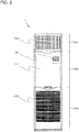
- Fig. 2 is a front view for illustrating a configuration of an exterior of the indoor unit 1 of the air-conditioning apparatus in the embodiment of the present invention.
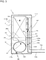
- Fig. 3 is a front view for schematically illustrating an internal structure of the indoor unit 1 of the air-conditioning apparatus in the embodiment of the present invention.
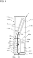
- Fig. 4 is a side view for schematically illustrating the internal structure of the indoor unit 1 of the air-conditioning apparatus in the embodiment of the present invention.
- the left of Fig. 4 indicates a front surface side (indoor space side) of the indoor unit 1.
- the indoor unit 1 of a floor type which is installed on a floor surface of an indoor space being an air-conditioned space, is described as an example.
- positional relationships for example, top-bottom relationship
- the indoor unit 1 includes a casing 111 having a longitudinally cuboid shape.
- An air inlet 112 configured to suck air inside the indoor space is formed in a lower portion of a front surface of the casing 111.
- the air inlet 112 in this embodiment is provided in a position proximate to the floor surface below a center portion of the casing 111 along a vertical direction of the air inlet 112.
- An air outlet 113 configured to blow off the air sucked from the air inlet 112 indoors is formed in the upper portion of the front surface of the casing 111, that is, in a position higher than the air inlet 112 (for example, above the center portion of the casing 111 along the vertical direction).
- the operation unit 26 is provided to the front surface of the casing 111 above the air inlet 112 and below the air outlet 113.
- the operation unit 26 is connected to the controller 30 through a communication line, and is capable of conducting mutual data communications to/from the controller 30.
- an operation-start manipulation, an operation-end manipulation, switching of an operation mode, setting of a set temperature and a set airflow rate, and other operations are conducted for the air-conditioning apparatus based on user's manipulations.
- the operation unit 26 includes a display unit or an audio output unit as an informing unit configured to inform the user of information.
- the casing 111 is a hollow box body, and the inside of the box body is an air passage.
- a front opening part is formed on a front surface of the casing 111.
- the casing 111 includes a first front panel 114a, a second front panel 114b, and a third front panel 114c, which are removably mounted to the front opening part.
- the first front panel 114a, the second front panel 114b, and the third front panel 114c all have a substantially rectangular flat outer shape.
- the first front panel 114a is removably mounted to a lower part of the front opening part of the casing 111. In the first front panel 114a, the air inlet 112 described above is formed.
- the second front panel 114b is arranged above the first front panel 114a such that they are adjacent to each other, and is removably mounted to a center part of the front opening part of the casing 111 along the vertical direction.
- the operation unit 26 described above is provided in the second front panel 114b.
- the third front panel 114c is arranged above the second front panel 114b such that they are adjacent to each other, and is removably mounted to an upper part of the front opening part of the casing 111.
- the air outlet 113 described above is formed.
- An internal space of the casing 111 is roughly divided into a space 115a being an air-sending part and a space 115b being a heat-exchanging part located above the space 115a.
- the space 115a and the space 115b are partitioned by a partition portion 20.
- the partition portion 20 has, for example, a flat shape, and is arranged approximately horizontally.
- at least an air passage opening part 20a is formed to serve as an air passage between the space 115a and the space 115b.
- the space 115a is exposed to the front surface side when the first front panel 114a is removed from the casing 111, and the space 115b is exposed to the front surface side when the second front panel 114b and the third front panel 114c are removed from the casing 111. That is, the partition portion 20 is mounted at approximately the same height as a height of an upper edge of the first front panel 114a or a lower edge of the second front panel 114b.
- the partition portion 20 may be formed integrally with a fan casing 108 to be described later, may be formed integrally with a drain pan to be described later, or may be formed separately from the fan casing 108 or the drain pan.
- the indoor air-sending fan 7f which is configured to cause a flow of air from the air inlet 112 to the air outlet 113 in the air passage 81 of the casing 111.
- the indoor air-sending fan 7f in this embodiment is a sirocco fan including a motor (not shown) and an impeller 107, which is connected to an output shaft of the motor and has a plurality of blades arranged, for example, at regular intervals along its circumferential direction.
- a rotary shaft of the impeller 107 is arranged substantially in parallel with a front-and-back direction of the casing 111.
- the rotation speed of the indoor air-sending fan 7f is controlled by the controller 30 based on a set airflow rate or other conditions set by the user so as to be variably set at multiple stages (for example, two stages or more) or continuously.
- the impeller 107 of the indoor air-sending fan 7f is covered with the fan casing 108 having a spiral shape.
- the fan casing 108 is formed, for example, separately from the casing 111.
- a suction opening part 108b for sucking the indoor air through the air inlet 112 into the fan casing 108 is formed near the center of a spiral of the fan casing 108.
- the suction opening part 108b is located so as to be opposed to the air inlet 112.
- an air outlet opening part 108a for blowing off the sent air is formed along a direction of a tangential line of the spiral of the fan casing 108.
- the air outlet opening part 108a is located so as to be directed upward, and is connected to the space 115b through the air passage opening part 20a of the partition portion 20. In other words, the air outlet opening part 108a communicates with the space 115b through the air passage opening part 20a.
- An opening end of the air outlet opening part 108a and an opening end of the air passage opening part 20a may be directly linked to each other, or may be indirectly linked to each other through a duct member or other members.
- an electric component box 25 accommodating, for example, a microcomputer that forms the controller 30, various types of electrical components, and a substrate.
- the load-side heat exchanger 7 is arranged in the air passage 81 within the space 115b.
- the drain pan (not shown) configured to receive condensed water that is condensed on a surface of the load-side heat exchanger 7 is provided below the load-side heat exchanger 7.
- the drain pan may be formed as a part of the partition portion 20, or may be formed separately from the partition portion 20 to be arranged on the partition portion 20.
- the load-side heat exchanger 7 is provided above the indoor air-sending fan 7f.
- the present invention is not limited to this configuration.
- the top-bottom relationship of the load-side heat exchanger 7 and the indoor air-sending fan 7f may be reversed.
- the load-side heat exchanger 7 and the indoor air-sending fan 7f may be arranged side by side.
- the refrigerant detection unit 99 is provided at a position closer to the bottom of the space 115a.
- the refrigerant has a density larger than that of air under an atmospheric pressure, and hence the refrigerant detection unit 99 is desired to be provided at a lower position inside the casing 111. Further, as described later, the refrigerant detection unit 99 is desired to be at a position lower than the position at which the refrigerant may leak (for example, a brazed portion of the load-side heat exchanger 7 and the joint portions 15a and 15b), and hence is desired to be provided in the lowermost position (bottom portion) of the casing 111.
- the refrigerant detection unit 99 is provided at a position closer to the bottom of the space 115a, but the refrigerant detection unit 99 may be provided at another position.
- a gas sensor for example, a semiconductor gas sensor or a hot-wire type semiconductor gas sensor, is used.
- the refrigerant detection unit 99 detects, for example, a refrigerant concentration within the air around the refrigerant detection unit 99, and outputs a detection signal to the controller 30.
- the controller 30 determines occurrance of leakage of the refrigerant based on the detection signal received from the refrigerant detection unit 99.
- an oxygen concentration meter or a temperature sensor for example, thermistor
- the refrigerant detection unit 99 detects temperature drop of the refrigerant that has leaked due to adiabatic expansion, to thereby detect the leakage of the refrigerant.
- the refrigerant detection unit 99 detects the refrigerant, and the controller 30 causes the indoor air-sending fan 7f to forcedly operate. At this time, all of the portions at which the refrigerant may leak are arranged inside the air passage.
- the refrigerant detection unit 99 is arranged inside the air passage and lower than the portions at which the refrigerant may leak. Therefore, when the refrigerant leaks, the refrigerant that has leaked can be detected by the refrigerant detection unit 99 before the refrigerant that has leaked flows out of the casing 111 of the indoor unit 1.
- the forced operation of the indoor air-sending fan 7f is continued for a time period (for example, 10 hours) set in advance based on the amount of the sealed refrigerant in the air-conditioning apparatus.
- an operation performed to operate or stop the indoor air-sending fan 7f when inspection and repair of leakage of the refrigerant is performed As methods of operating or stopping the indoor air-sending fan 7f, there are given, as a first method, a method of operating or stopping the indoor air-sending fan 7f by turning on or off a main power source (breaker), and, as a second method, a method of stopping or starting (restarting) the forced operation of the indoor air-sending fan 7f by a special manipulation on the operation unit 26.
- the indoor air-sending fan 7f is supplied with power from the main power source (breaker), and thus the indoor air-sending fan 7f is stopped when the main power source (breaker) is turned off, and the operation of the indoor air-sending fan 7f is started (restarted) when the main power source (breaker) is turned on.
- the main power source (breaker) is turned off or on to stop or operate the indoor air-sending fan 7f so that the safety of the work is secured.
- the second method that is, the method of stopping or starting (restarting) the forced operation of the indoor air-sending fan 7f by means of the special manipulation on the operation unit 26.
- the controller 30 is configured to execute, as operation modes of the indoor air-sending fan 7f, a first operation mode, in which a normal air-sending operation is performed, and a second operation mode, in which a forced operation is performed when the refrigerant leaks.
- the first operation mode is executed based on, as a first manipulation, an operation of starting the normal operation of the indoor air-sending fan 7f performed on the operation unit 26, and, as a second manipulation, an operation of stopping the normal operation of the indoor air-sending fan 7f performed on the operation unit 26.
- the second operation mode is the following operation mode.
- the operation of the indoor air-sending fan 7f is started when leakage of the refrigerant is detected by the refrigerant detection unit 99, and the indoor air-sending fan 7f is forcedly stopped based on a third manipulation different from the second manipulation without being stopped based on the above-mentioned second manipulation. Then, the forced operation of the indoor air-sending fan 7f is restarted based on a fourth manipulation different from the first manipulation.
- the third manipulation and fourth manipulation differ from the normal first manipulation and second manipulation, which are performed by the user via the operation unit 26 on the air-conditioning apparatus.
- the third manipulation and fourth manipulation are so-called special manipulations used when the service person performs the inspection and repair of the air-conditioning apparatus.
- the state in which the normal first manipulation and second manipulation, which are performed by the user or another person via the operation unit 26, are received can be switched to the state in which the third manipulation and fourth manipulation, which are the special manipulations, are received only by a method that can only be performed by a professional service person.
- the service person may be required to temporarily leave the site in order to obtain necessary replacement parts at a service center or another place after taking temporary measures.
- the window or the door may be required to be closed (locked) for security reasons, and thus, when the indoor air-sending fan 7f is kept stopped, a flammable concentration region (for example, region in which the refrigerant concentration is equal to or larger than the lower flammability limit (LFL)) may be formed in the indoor space.
- LFL lower flammability limit
- the main power source (breaker) is not required to be turned on or off. That is, it is not required to frequently check the main power source (breaker), which is generally provided at a position distant from the installation position of the indoor unit, and thus an effect that the workability of the service person can also be improved can be obtained.
- the service person being a professional operator is responsible for (is in a position to be responsible for) securing the safety and securing the ventilation, that is, taking a measure for preventing the flammable concentration region from being formed in the indoor space, until the inspection and repair is finished. For that reason, there is no problem even when the service person is enabled to stop or start (restart) the forced operation of the indoor air-sending fan 7f.
- Fig. 5 is a time chart for illustrating a relationship between an operation of the main power source (breaker) of the air-conditioning apparatus and the forced operation (second operation mode) of the indoor air-sending fan 7f in the embodiment of the present invention.
- Fig. 6 is a time chart for illustrating the state of the forced operation (second operation mode) of the indoor air-sending fan 7f in a case where the special manipulation of the air-conditioning apparatus is performed in the embodiment of the present invention.
- the indoor air-sending fan 7f is forcedly operated until the operation time thereof reaches a reference time (for example, 10 hours) set in advance.
- the first method involves continuing repeatedly operating the indoor air-sending fan 7f until the continuous operation time thereof reaches the reference time.
- This first operation method is used when the indoor air-sending fan 7f is operated or stopped based on the operation of turning on or off the main power source (breaker) in the above-mentioned first method.
- the second method involves continuing operating the indoor air-sending fan 7f until the integrated operation time thereof reaches the reference time. This second operation method is used when the forced operation of the indoor air-sending fan 7f is stopped or started (restarted) by means of the special manipulation on the operation unit 26 in the above-mentioned second method.
- the indoor air-sending fan 7f in a case where the time period (reference time) of the forced operation of the indoor air-sending fan 7f is set to 10 hours, when leakage of the refrigerant is detected with no time having elapsed, the indoor air-sending fan 7f is automatically started to forcedly operate because the main power source (breaker) is turned on. However, for example, when the main power source (breaker) is turned off when 7 hours, which are less than 10 hours being the reference time, have elapsed, the indoor air-sending fan 7f is stopped operating at the same time.
- the continuous operation time of the indoor air-sending fan 7f is less than 10 hours being the reference time, and hence, when the main power source (breaker) is turned on thereafter, the controller 30 causes the indoor air-sending fan 7f to start to operate again.
- the indoor air-sending fan 7f being operated from a point of time when 13 hours have elapsed to a point of time when 23 hours have elapsed
- a continuous operation of the indoor air-sending fan 7f is performed up to 10 hours being the reference time, and thus the forced operation can be ended. In this manner, a longer time period of the forced operation of the indoor air-sending fan 7f can be secured.
- the above-mentioned time and the time indicated in Fig. 5 are merely examples, and the present invention is not limited to the time exemplified above.
- the fact that the integrated operation time of the indoor air-sending fan 7f is 7 hours is stored in the clock unit 30a.
- the operation time of the indoor air-sending fan 7f after the restart of the operation has reached 3 hours (i.e.
- the controller 30 causes the clock unit 30a to integrate the operation time of the indoor air-sending fan 7f, and determines whether or not the integrated operation time has reached the reference time. Then, when the integrated operation time has reached the reference time, the controller 30 stops the operation of the indoor air-sending fan 7f. In this manner, it is possible to execute the forced operation of the indoor air-sending fan 7f for the time period set in advance based on the amount of the sealed refrigerant in the air-conditioning apparatus.
- the above-mentioned time and the time indicated in Fig. 6 are merely examples, and the present invention is not limited to the time exemplified above.
- Fig. 7 is a flow chart for illustrating an example of the flow of refrigerant leakage detection processing executed by the controller 30 of the air-conditioning apparatus in the embodiment of the present invention.
- the refrigerant leakage detection processing is executed repeatedly at all times including a period in which the air-conditioning apparatus is operating and is stopped.
- Step S1 of Fig. 7 the controller 30 acquires information on the refrigerant concentration around the refrigerant detection unit 99 based on the detection signal received from the refrigerant detection unit 99.
- Step S2 it is determined whether or not the refrigerant concentration around the refrigerant detection unit 99 is equal to or larger than a threshold value set in advance.
- the processing proceeds to Step S3, and when the refrigerant concentration is smaller than the threshold value, the processing of Step S2 is repeatedly performed.
- Step S3 the forced operation (second operation mode) of the indoor air-sending fan 7f is started.
- the rotation speed of the indoor air-sending fan 7f may be set to a rotation speed at which the refrigerant can be sufficiently diffused even when the refrigerant leakage amount is at the maximum.
- the rotation speed is not limited to the rotation speed used during the normal operation.
- the informing unit for example, display unit or audio output unit provided in the operation unit 26 may be used to inform the user that leakage of the refrigerant has occurred.
- Step S4 it is determined whether or not a manipulation (third manipulation of the second operation mode) of stopping the indoor air-sending fan 7f is performed as the special manipulation.
- a manipulation third manipulation of the second operation mode
- Step S5 the indoor air-sending fan 7f is stopped. Then, the processing proceeds to Step S6.
- Step S6 it is determined whether or not a manipulation (fourth manipulation of the second operation mode) of restarting the operation of the indoor air-sending fan 7f is performed as the special manipulation.
- a manipulation fourth manipulation of the second operation mode
- the processing proceeds to Step S7, and when the manipulation of restarting the operation of the indoor air-sending fan 7f is not performed as the special manipulation, the processing of Step S6 is repeatedly performed.
- Step S7 the operation of the indoor air-sending fan 7f is restarted. Then, the processing proceeds to Step S8.
- Step S8 it is determined whether or not the integrated operation time of the indoor air-sending fan 7f has exceeded the reference time (for example, 10 hours).
- the processing proceeds to Step S9, and when the integrated operation time of the indoor air-sending fan 7f has not exceeded the reference time yet, the processing proceeds to Step S4.
- Step S9 the indoor air-sending fan 7f is stopped.
- the indoor air-sending fan 7f is started to operate. With this operation, it is possible to diffuse the refrigerant that has leaked, and thus it is possible to inhibit the refrigerant concentration from increasing locally in the indoor space.
- examples of the refrigerant to be circulated by the refrigerant circuit 40 include flammable refrigerants such as HFO-1234yf, HFO-1234ze, R290, and R1270. Therefore, if leakage of refrigerant occurs in the indoor unit 1, there is a fear that the indoor refrigerant concentration is increased to form a flammable concentration region.
- Those flammable refrigerants have a density larger than that of air under the atmospheric pressure. Therefore, when the leakage of the refrigerant occurs at a position at which the height from the floor surface of the indoor space is relatively high, the refrigerant that has leaked is diffused while descending. Thus, the refrigerant concentration becomes uniform in the indoor space, and hence the refrigerant concentration is less liable to be increased. In contrast, when the leakage of the refrigerant occurs at a position at which the height from the floor surface of the indoor space is low, the refrigerant that has leaked remains at a low position near the floor surface, and hence the refrigerant concentration tends to be locally increased. As a result, the risk of the formation of the flammable concentration region is relatively increased.
- the forced operation (second operation mode) of the indoor air-sending fan 7f is started when the leakage of the refrigerant is detected, and hence it is possible to inhibit the flammable concentration region from being formed in the indoor space even when the flammable refrigerant leaks to the indoor space during the period in which the air-conditioning apparatus is stopped.
- the present invention is not limited to the above-mentioned embodiment, and various modifications may be made thereto.
- the indoor unit 1 is exemplified, but the present invention can also be applied to an outdoor unit.
- the present invention can also be applied to other refrigeration cycle apparatuses or other refrigeration cycle systems such as a heat pump water heater, a chiller, and a showcase.
- the refrigeration cycle apparatus including: the refrigerant circuit 40 configured to circulate the refrigerant; the indoor unit 1 configured to accommodate at least the load-side heat exchanger 7 of the refrigerant circuit 40; the controller 30 configured to control the indoor unit 1; and the operation unit 26 configured to receive manipulations on the indoor unit 1.
- the indoor unit 1 includes the refrigerant detection unit 99 and the indoor air-sending fan 7f.
- the controller 30 is configured to execute the first operation mode and the second operation mode as the operation modes of the indoor air-sending fan 7f.
- the first operation mode is an operation mode in which the operation of the indoor air-sending fan 7f is started based on the first manipulation performed on the operation unit 26 and the indoor air-sending fan 7f is stopped based on the second manipulation performed on the operation unit 26.
- the second operation mode is an operation mode in which the operation of the indoor air-sending fan 7f is started when the refrigerant is detected by the refrigerant detection unit 99, the indoor air-sending fan 7f is not stopped based on the second manipulation, the indoor air-sending fan 7f is stopped based on the third manipulation different from the second manipulation, and the operation of the indoor air-sending fan 7f is restarted based on the fourth manipulation different from the first manipulation.
- the controller 30 executes the second operation mode so that the forced operation of the indoor air-sending fan 7f is started, and hence it is possible to inhibit the flammable concentration region from being formed locally.
- the indoor air-sending fan 7f is not stopped based on the second manipulation for stopping the normal operation (first operation mode). Therefore, it is possible to prevent a user or another person who does not know the cause of leakage and how the inspection and repair was performed from stopping the indoor air-sending fan 7f in the forced operation on his or her own judgment. Consequently, it is possible to prevent the flammable concentration region from being formed locally.
- the indoor air-sending fan 7f is stopped based on the third manipulation different from the second manipulation. Therefore, when a service person begins the inspection and repair of the air-conditioning apparatus, it is possible to secure the safety during the inspection and repair by stopping the indoor air-sending fan 7f in the forced operation. Further, in the second operation mode, the operation of the indoor air-sending fan 7f is restarted based on the fourth manipulation different from the first manipulation for starting the normal operation. Therefore, at the time when the service person leaves the site of the inspection and repair, it is possible to inhibit the flammable concentration region from being formed locally by restarting the forced operation of the indoor air-sending fan 7f.
- controller 30 include the clock unit 30a configured to clock the operation time of the indoor air-sending fan 7f in the second operation mode, and that the controller 30 be configured to execute the second operation mode until the continuous operation time reaches the reference time.
- controller 30 include the clock unit 30a configured to clock the operation time of the indoor air-sending fan 7f in the second operation mode, and that the controller 30 be configured to execute the second operation mode until the integrated operation time reaches the reference time.
- the indoor air-sending fan 7f is operated until the continuous or integrated operation time of the indoor air-sending fan 7f reaches the reference time. Consequently, even when the flammable refrigerant leaks, the refrigerant that has leaked is sufficiently stirred, and hence it is possible to inhibit the flammable concentration region from being formed locally.
Landscapes
- Engineering & Computer Science (AREA)
- Mechanical Engineering (AREA)
- General Engineering & Computer Science (AREA)
- Chemical & Material Sciences (AREA)
- Combustion & Propulsion (AREA)
- Physics & Mathematics (AREA)
- Thermal Sciences (AREA)
- Human Computer Interaction (AREA)
- Signal Processing (AREA)
- Fluid Mechanics (AREA)
- Fuzzy Systems (AREA)
- Mathematical Physics (AREA)
- Air Conditioning Control Device (AREA)
Abstract
Description
- The present invention relates to a refrigeration cycle apparatus including an air-sending fan.
- In
Patent Literature 1, there is described an indoor unit of an air-conditioning apparatus. This indoor unit includes a refrigerant detection unit configured to detect leakage of refrigerant, a controller configured to perform, when the refrigerant detection unit detects leakage of the refrigerant, control for causing an air-sending fan to forcedly rotate and causing a warning device to issue a warning, and an operation device for inputting, to the controller, a stop command for the air-sending fan and the warning device based on a manual operation of the operation unit. In this indoor unit, after issuance of a warning was started once, sound output (buzzer) output from the warning device can be stopped by manipulations on the operation device performed by a user even before a service person arrives and performs inspection and repair. Therefore, a cause of noise that bothers its vicinities can be eliminated, with the result that dissatisfaction of the user can be get rid of. - Patent Literature 1: Japanese Patent No.
5812081 - When the service person arrives and starts the inspection and repair of the air-conditioning apparatus, the air-sending fan is required to be temporarily stopped for the inspection and repair in some cases. However, in
Patent Literature 1, there is no description on whether or not the air-sending fan can be temporarily stopped. - Further, depending on the details of a repair in accordance with each occurrence of failure of the air-conditioning apparatus, in some cases, there is no other choice but to take temporary measures for the time being and temporarily leave the site of the inspection and repair, and then take permanent measures (for example, a case in which repair parts are required to be prepared anew as a result of the inspection). In such a case, when the service person leaves the site of the inspection and repair, the air-sending fan is required to be operated again so that a refrigerant concentration is not increased locally. However, in
Patent Literature 1, there is no description on whether or not the operation of the air-sending fan of the indoor unit can be started again after being temporarily stopped. Moreover, in general, the air-conditioning apparatus includes three operation modes, namely, a cooling mode, a heating mode, and an air-sending mode, and hence it is possible to perform the operation of the air-sending fan in the air-sending mode by manipulating a remote controller serving as the operation device. However, the operation of the air-sending fan in the air-sending mode can be disadvantageously stopped through a manipulation of the remote controller performed by the user or another person. Accordingly, the user or another person who does not know the cause of leakage and how the inspection and repair was performed may stop the operation of the air-sending fan through the manipulation of the remote controller on his or her own judgment. As a result, there may be a place at which a concentration of refrigerant that has leaked is increased locally in an indoor space. - The present invention has been made in view of the above-mentioned problems, and it is an object of the present invention to provide a refrigeration cycle apparatus capable of inhibiting a refrigerant concentration of refrigerant that has leaked from increasing locally.
- According to one embodiment of the present invention, there is provided a refrigeration cycle apparatus including: a refrigerant circuit configured to circulate refrigerant; an indoor unit configured to accommodate at least a load-side heat exchanger of the refrigerant circuit; a controller configured to control the indoor unit; and an operation unit configured to receive a manipulation on the indoor unit, the indoor unit including: a refrigerant detection unit; and an air-sending fan, the controller being configured to cause a first operation mode and a second operation mode to be executed as operation modes of the air-sending fan, the first operation mode being an operation mode in which an operation of the air-sending fan is started based on a first operation performed on the operation unit and the air-sending fan is stopped based on a second operation performed on the operation unit, the second operation mode being an operation mode in which the operation of the air-sending fan is started when refrigerant is detected by the refrigerant detection unit, the air-sending fan is prevented from being stopped based on the second manipulation, the air-sending fan is stopped based on a third manipulation different from the second manipulation, and the operation of the air-sending fan is restarted based on a fourth manipulation different from the first manipulation.
- In the refrigeration cycle apparatus according to one embodiment of the present invention, the operation of the air-sending fan is started when refrigerant is detected by the refrigerant detection unit, the air-sending fan is stopped based on the third operation different from the second operation, and the operation of the air-sending fan is restarted based on the fourth manipulation different from the first manipulation. In this manner, it is possible to inhibit the refrigerant concentration of the refrigerant that has leaked from increasing locally.
-
- [
Fig. 1] Fig. 1 is a refrigerant circuit diagram for illustrating a schematic configuration of an air-conditioning apparatus in an embodiment of the present invention. - [
Fig. 2] Fig. 2 is a front view for illustrating a configuration of an exterior of anindoor unit 1 of the air-conditioning apparatus in the embodiment of the present invention. - [
Fig. 3] Fig. 3 is a front view for schematically illustrating an internal structure of theindoor unit 1 of the air-conditioning apparatus in the embodiment of the present invention. - [
Fig. 4] Fig. 4 is a side view for schematically illustrating the internal structure of theindoor unit 1 of the air-conditioning apparatus in the embodiment of the present invention. - [
Fig. 5] Fig. 5 is a time chart for illustrating a relationship between an operation of a main power source (breaker) of the air-conditioning apparatus and a forced operation (second operation mode) of an indoor air-sendingfan 7f in the embodiment of the present invention. - [
Fig. 6] Fig. 6 is a time chart for illustrating a state of the forced operation (second operation mode) of the indoor air-sendingfan 7f in a case where a special manipulation of the air-conditioning apparatus is performed in the embodiment of the present invention. - [
Fig. 7] Fig. 7 is a flow chart for illustrating an example of refrigerant leakage detection processing executed by acontroller 30 of the air-conditioning apparatus in the embodiment of the present invention. - A refrigeration cycle apparatus according to an embodiment of the present invention is described. In this embodiment, an air-conditioning apparatus is exemplified as the refrigeration cycle apparatus.
Fig. 1 is a refrigerant circuit diagram for illustrating a schematic configuration of the air-conditioning apparatus in the embodiment of the present invention. InFig. 1 and the subsequent figures, each component may have a dimensional relationship, a shape, and the like that are different from actual ones. - As illustrated in
Fig. 1 , the air-conditioning apparatus includes arefrigerant circuit 40 configured to circulate refrigerant. Therefrigerant circuit 40 includes acompressor 3, a refrigerant flow switching device 4, a heat source-side heat exchanger 5 (for example, outdoor heat exchanger), a pressure reducing device 6, and a load-side heat exchanger 7 (for example, indoor heat exchanger), which are sequentially connected to form a circuit through refrigerant pipes. Further, the air-conditioning apparatus includes anoutdoor unit 2, which is installed, for example, outdoors as a heat source unit. Further, the air-conditioning apparatus includes anindoor unit 1, which is installed, for example, indoors as a load unit. Theindoor unit 1 and theoutdoor unit 2 are connected to each other throughextension pipes - Examples of a refrigerant to be used as the refrigerant to be circulated by the
refrigerant circuit 40 include a slightly flammable refrigerant such as HFO-1234yf or HFO-1234ze and a strongly flammable refrigerant such as R290 or R1270. Each of those refrigerants may be used as a single-component refrigerant, or may be used as a mixed refrigerant obtained by mixing two or more kinds of the refrigerants with each other. In the following description, the refrigerant having a flammability equal to or higher than a slightly flammable level (for example, 2L or higher in category of ASHRAE34) is often referred to as "flammable refrigerant". Further, as the refrigerant to be circulated by therefrigerant circuit 40, a nonflammable refrigerant having a nonflammability (for example, 1 in category of ASHRAE34), such as R22 or R410A, can be used. Those refrigerants have a density larger than that of air under an atmospheric pressure (for example, the temperature is room temperature (25 degrees C)). - The
compressor 3 is a fluid machine configured to compress a sucked low-pressure refrigerant and to discharge the low-pressure refrigerant as high-pressure refrigerant. The refrigerant flow switching device 4 is configured to switch a flow direction of the refrigerant within therefrigerant circuit 40 between a cooling operation and a heating operation. As the refrigerant flow switching device 4, for example, a four-way valve is used. The heat source-side heat exchanger 5 is a heat exchanger configured to function as a radiator (for example, condenser) in the cooling operation and to function as an evaporator in the heating operation. The heat source-side heat exchanger 5 exchanges heat between the refrigerant circulated through an inside of the heat source-side heat exchanger 5 and outdoor air sent by an outdoor air-sending fan 5f to be described later. The pressure reducing device 6 is configured to reduce the pressure of the high-pressure refrigerant such that the high-pressure refrigerant becomes the low-pressure refrigerant. As the pressure reducing device 6, for example, an electronic expansion valve capable of adjusting its opening degree is used. The load-side heat exchanger 7 is a heat exchanger configured to function as an evaporator in the cooling operation and to function as a radiator (for example, condenser) in the heating operation. The load-side heat exchanger 7 exchanges heat between the refrigerant circulated through an inside of the load-side heat exchanger 7 and air sent by an indoor air-sendingfan 7f to be described later. In this case, the cooling operation represents an operation for supplying low-temperature and low-pressure refrigerant to the load-side heat exchanger 7, and the heating operation represents an operation for supplying high-temperature and high-pressure refrigerant to the load-side heat exchanger 7. - The
outdoor unit 2 accommodates thecompressor 3, the refrigerant flow switching device 4, the heat source-side heat exchanger 5, and the pressure reducing device 6. Further, theoutdoor unit 2 accommodates the outdoor air-sending fan 5f configured to supply outdoor air to the heat source-side heat exchanger 5. The outdoor air-sending fan 5f is installed so as to be opposed to the heat source-side heat exchanger 5. When the outdoor air-sending fan 5f is rotated, an airflow passing through the heat source-side heat exchanger 5 is generated. As the outdoor air-sending fan 5f, for example, a propeller fan is used. The outdoor air-sending fan 5f is arranged on, for example, downstream of the heat source-side heat exchanger 5 along the airflow generated by the outdoor air-sending fan 5f. - The refrigerant pipes arranged in the
outdoor unit 2 include a refrigerant pipe configured to connect between an extension pipe connection valve 13a on a side at which the refrigerant becomes a gas phase in the cooling operation (hereinafter referred to as the "gas side" and the refrigerant flow switching device 4, asuction pipe 11 connected to a suction side of thecompressor 3, adischarge pipe 12 connected to a discharge side of thecompressor 3, a refrigerant pipe configured to connect between the refrigerant flow switching device 4 and the heat source-side heat exchanger 5, a refrigerant pipe configured to connect between the heat source-side heat exchanger 5 and the pressure reducing device 6, and a refrigerant pipe configured to connect between an extension pipe connection valve 13b on a side at which the refrigerant becomes a liquid phase in the cooling operation (hereinafter referred to as the "liquid side" and the pressure reducing device 6. The extension pipe connection valve 13a includes a two-way valve capable of switching between open and close, and has one end to which a flare joint is mounted. Further, the extension pipe connection valve 13b includes a three-way valve capable of switching between open and close. The extension pipe connection valve 13b has one end to which a service port 14a is mounted, which is used at a time of vacuuming being a preliminary work of filling therefrigerant circuit 40 with refrigerant, and the other end to which a flare joint is mounted. - In both the cooling operation and the heating operation, high-temperature and high-pressure gas refrigerant compressed by the
compressor 3 flows through thedischarge pipe 12. In both the cooling operation and the heating operation, low-temperature and low-pressure gas refrigerant or two-phase refrigerant subjected to an evaporation action flows through thesuction pipe 11. Thesuction pipe 11 is connected to a low-pressure-side service port 14b with a flare joint, and thedischarge pipe 12 is connected to a high-pressure-side service port 14c with a flare joint. The service ports 14b and 14c are used to connect a pressure gauge thereto to measure the operating pressure at a time of installation of the air-conditioning apparatus or at a time of a trial run for a repair. - The
indoor unit 1 has, in its inside, at least the load-side heat exchanger 7 (for example, indoor heat exchanger), the indoor air-sendingfan 7f configured to supply air to the load-side heat exchanger 7,joint portions refrigerant detection unit 99. Those components are provided inside an air passage of acasing 111 to be described later. When the indoor air-sendingfan 7f is rotated, an airflow passing through the load-side heat exchanger 7 is generated. As the indoor air-sendingfan 7f, a centrifugal fan (for example, sirocco fan or turbofan), a cross flow fan, a mixed flow fan, an axial fan (for example, propeller fan), or other fans is used depending on a shape of theindoor unit 1. The indoor air-sendingfan 7f in this embodiment is arranged on upstream of the load-side heat exchanger 7 along the airflow generated by the indoor air-sendingfan 7f, but may be arranged on downstream of the load-side heat exchanger 7. - Of the refrigerant pipes of the
indoor unit 1, a gas-sideindoor pipe 9a is provided in a connection portion to the gas-side extension pipe 10a with ajoint portion 15a (for example, flare joint) for connection to theextension pipe 10a. Further, of the refrigerant pipes of theindoor unit 1, a liquid-sideindoor pipe 9b is provided in a connection portion to the liquid-side extension pipe 10b with ajoint portion 15b (for example, flare joint) for connection to theextension pipe 10b. - Further, the
indoor unit 1 includes a suctionair temperature sensor 91 configured to detect a temperature of indoor air sucked from the indoors, a heat exchangerentrance temperature sensor 92 configured to detect a refrigerant temperature at an entrance portion of the load-side heat exchanger 7 in the cooling operation (exit portion of the load-side heat exchanger 7 in the heating operation), and a heatexchanger temperature sensor 93 configured to detect a refrigerant temperature (evaporating temperature or condensing temperature) of a two-phase portion of the load-side heat exchanger 7. In addition, theindoor unit 1 includes a refrigerant detection unit 99 (for example, semiconductor gas sensor) to be described later. Those sensors are configured to output a detection signal to acontroller 30 configured to control an entirety of theindoor unit 1 or the air-conditioning apparatus. - The
controller 30 includes a microcomputer including a CPU, a ROM, a RAM, an I/O port, and a timer. Further, thecontroller 30 also includes a clock unit 30a configured to clock operation time of the indoor air-sendingfan 7f, which is to be described later. Thecontroller 30 can conduct data communications to/from an operation unit 26 (seeFig. 2 ). Theoperation unit 26 is configured to receive manipulation performed by a user to output to thecontroller 30 an operation signal based on the manipulation. Thecontroller 30 in this embodiment controls the operation of the entirety of theindoor unit 1 or the air-conditioning apparatus including an operation of the indoor air-sendingfan 7f based on an operation signal received from theoperation unit 26, detection signals received from the sensors, or other signals. Further, thecontroller 30 in this embodiment can conduct switching between energization and non-energization to therefrigerant detection unit 99. Thecontroller 30 may be provided inside a casing of theindoor unit 1, or may be provided inside a casing of theoutdoor unit 2. Further, thecontroller 30 may include an outdoor unit controller provided to theoutdoor unit 2 and an indoor unit controller that is provided to theindoor unit 1 and capable of conducting data communications to/from the outdoor unit controller. - Next, description is given of the operation of the
refrigerant circuit 40 of the air-conditioning apparatus. First, the operation in the cooling operation is described. InFig. 1 , the solid arrows indicate flow directions of the refrigerant in the cooling operation. Therefrigerant circuit 40 is configured so that, in the cooling operation, a refrigerant flow passage is switched as indicated by the solid line by the refrigerant flow switching device 4 and the low-temperature and low-pressure refrigerant flows into the load-side heat exchanger 7. - The high-temperature and high-pressure gas refrigerant discharged from the
compressor 3 first flows into the heat source-side heat exchanger 5 after passing through the refrigerant flow switching device 4. In the cooling operation, the heat source-side heat exchanger 5 functions as a condenser. That is, the heat source-side heat exchanger 5 exchanges heat between the refrigerant circulated through the inside and the outdoor air sent by the outdoor air-sending fan 5f, and heat of condensation of the refrigerant is transferred to the outdoor air. With this operation, the refrigerant that has flowed into the heat source-side heat exchanger 5 is condensed to become high-pressure liquid refrigerant. The high-pressure liquid refrigerant flows into the pressure reducing device 6, and has the pressure reduced to become low-pressure two-phase refrigerant. The low-pressure two-phase refrigerant passes through theextension pipe 10b, and flows into the load-side heat exchanger 7 of theindoor unit 1. In the cooling operation, the load-side heat exchanger 7 functions as an evaporator. That is, the load-side heat exchanger 7 exchanges heat between the refrigerant circulated through the inside and the air (for example, indoor air) sent by the indoor air-sendingfan 7f, and heat of evaporation of the refrigerant is received from the sent air. With this operation, the refrigerant that has flowed into the load-side heat exchanger 7 evaporates to become low-pressure gas refrigerant or two-phase refrigerant with high quality. Further, the air sent by the indoor air-sendingfan 7f is cooled by a heat receiving action of the refrigerant. The low-pressure gas refrigerant or two-phase refrigerant with high quality evaporated by the load-side heat exchanger 7 passes through theextension pipe 10a and the refrigerant flow switching device 4, and is sucked by thecompressor 3. The refrigerant sucked by thecompressor 3 is compressed to become the high-temperature and high-pressure gas refrigerant. In the cooling operation, the above-mentioned cycle is repeated. - Next, the operation in the heating operation is described. In
Fig. 1 , the dotted arrows indicate flow directions of the refrigerant in the heating operation. Therefrigerant circuit 40 is configured so that, in the heating operation, the refrigerant flow passage is switched as indicated by the dotted line by the refrigerant flow switching device 4, and the high-temperature and high-pressure refrigerant flows into the load-side heat exchanger 7. In the heating operation, the refrigerant flows in a direction reverse to that of the cooling operation, and the load-side heat exchanger 7 functions as a condenser. That is, the load-side heat exchanger 7 exchanges heat between the refrigerant circulated through the inside and the air sent by the indoor air-sendingfan 7f, and the heat of condensation of the refrigerant is transferred to the sent air. With this operation, the air sent by the indoor air-sendingfan 7f is heated by a heat transferring action of the refrigerant. -
Fig. 2 is a front view for illustrating a configuration of an exterior of theindoor unit 1 of the air-conditioning apparatus in the embodiment of the present invention.Fig. 3 is a front view for schematically illustrating an internal structure of theindoor unit 1 of the air-conditioning apparatus in the embodiment of the present invention.Fig. 4 is a side view for schematically illustrating the internal structure of theindoor unit 1 of the air-conditioning apparatus in the embodiment of the present invention. The left ofFig. 4 indicates a front surface side (indoor space side) of theindoor unit 1. In this embodiment, as theindoor unit 1, theindoor unit 1 of a floor type, which is installed on a floor surface of an indoor space being an air-conditioned space, is described as an example. In the following description, positional relationships (for example, top-bottom relationship) between components are, in principle, exhibited when theindoor unit 1 is installed in a usable state. - As illustrated in
Fig. 2 to Fig. 4 , theindoor unit 1 includes acasing 111 having a longitudinally cuboid shape. Anair inlet 112 configured to suck air inside the indoor space is formed in a lower portion of a front surface of thecasing 111. Theair inlet 112 in this embodiment is provided in a position proximate to the floor surface below a center portion of thecasing 111 along a vertical direction of theair inlet 112. Anair outlet 113 configured to blow off the air sucked from theair inlet 112 indoors is formed in the upper portion of the front surface of thecasing 111, that is, in a position higher than the air inlet 112 (for example, above the center portion of thecasing 111 along the vertical direction). Theoperation unit 26 is provided to the front surface of thecasing 111 above theair inlet 112 and below theair outlet 113. Theoperation unit 26 is connected to thecontroller 30 through a communication line, and is capable of conducting mutual data communications to/from thecontroller 30. In theoperation unit 26, an operation-start manipulation, an operation-end manipulation, switching of an operation mode, setting of a set temperature and a set airflow rate, and other operations are conducted for the air-conditioning apparatus based on user's manipulations. Theoperation unit 26 includes a display unit or an audio output unit as an informing unit configured to inform the user of information. - The
casing 111 is a hollow box body, and the inside of the box body is an air passage. A front opening part is formed on a front surface of thecasing 111. Thecasing 111 includes a firstfront panel 114a, a secondfront panel 114b, and a thirdfront panel 114c, which are removably mounted to the front opening part. The firstfront panel 114a, the secondfront panel 114b, and the thirdfront panel 114c all have a substantially rectangular flat outer shape. The firstfront panel 114a is removably mounted to a lower part of the front opening part of thecasing 111. In the firstfront panel 114a, theair inlet 112 described above is formed. The secondfront panel 114b is arranged above the firstfront panel 114a such that they are adjacent to each other, and is removably mounted to a center part of the front opening part of thecasing 111 along the vertical direction. In the secondfront panel 114b, theoperation unit 26 described above is provided. The thirdfront panel 114c is arranged above the secondfront panel 114b such that they are adjacent to each other, and is removably mounted to an upper part of the front opening part of thecasing 111. In the thirdfront panel 114c, theair outlet 113 described above is formed. - An internal space of the
casing 111 is roughly divided into aspace 115a being an air-sending part and aspace 115b being a heat-exchanging part located above thespace 115a. Thespace 115a and thespace 115b are partitioned by apartition portion 20. Thepartition portion 20 has, for example, a flat shape, and is arranged approximately horizontally. In thepartition portion 20, at least an airpassage opening part 20a is formed to serve as an air passage between thespace 115a and thespace 115b. Thespace 115a is exposed to the front surface side when the firstfront panel 114a is removed from thecasing 111, and thespace 115b is exposed to the front surface side when the secondfront panel 114b and the thirdfront panel 114c are removed from thecasing 111. That is, thepartition portion 20 is mounted at approximately the same height as a height of an upper edge of the firstfront panel 114a or a lower edge of the secondfront panel 114b. In this case, thepartition portion 20 may be formed integrally with afan casing 108 to be described later, may be formed integrally with a drain pan to be described later, or may be formed separately from thefan casing 108 or the drain pan. - In the
space 115a, the indoor air-sendingfan 7f, which is configured to cause a flow of air from theair inlet 112 to theair outlet 113 in theair passage 81 of thecasing 111, is arranged. The indoor air-sendingfan 7f in this embodiment is a sirocco fan including a motor (not shown) and animpeller 107, which is connected to an output shaft of the motor and has a plurality of blades arranged, for example, at regular intervals along its circumferential direction. A rotary shaft of theimpeller 107 is arranged substantially in parallel with a front-and-back direction of thecasing 111. The rotation speed of the indoor air-sendingfan 7f is controlled by thecontroller 30 based on a set airflow rate or other conditions set by the user so as to be variably set at multiple stages (for example, two stages or more) or continuously. - The
impeller 107 of the indoor air-sendingfan 7f is covered with thefan casing 108 having a spiral shape. Thefan casing 108 is formed, for example, separately from thecasing 111. Asuction opening part 108b for sucking the indoor air through theair inlet 112 into thefan casing 108 is formed near the center of a spiral of thefan casing 108. Thesuction opening part 108b is located so as to be opposed to theair inlet 112. Further, an airoutlet opening part 108a for blowing off the sent air is formed along a direction of a tangential line of the spiral of thefan casing 108. The airoutlet opening part 108a is located so as to be directed upward, and is connected to thespace 115b through the airpassage opening part 20a of thepartition portion 20. In other words, the airoutlet opening part 108a communicates with thespace 115b through the airpassage opening part 20a. An opening end of the airoutlet opening part 108a and an opening end of the airpassage opening part 20a may be directly linked to each other, or may be indirectly linked to each other through a duct member or other members. - Further, in the
space 115a, there is provided anelectric component box 25 accommodating, for example, a microcomputer that forms thecontroller 30, various types of electrical components, and a substrate. - The load-
side heat exchanger 7 is arranged in theair passage 81 within thespace 115b. The drain pan (not shown) configured to receive condensed water that is condensed on a surface of the load-side heat exchanger 7 is provided below the load-side heat exchanger 7. The drain pan may be formed as a part of thepartition portion 20, or may be formed separately from thepartition portion 20 to be arranged on thepartition portion 20. In this embodiment, there is described an example in which the load-side heat exchanger 7 is provided above the indoor air-sendingfan 7f. However, the present invention is not limited to this configuration. The top-bottom relationship of the load-side heat exchanger 7 and the indoor air-sendingfan 7f may be reversed. Alternatively, the load-side heat exchanger 7 and the indoor air-sendingfan 7f may be arranged side by side. - The
refrigerant detection unit 99 is provided at a position closer to the bottom of thespace 115a. The refrigerant has a density larger than that of air under an atmospheric pressure, and hence therefrigerant detection unit 99 is desired to be provided at a lower position inside thecasing 111. Further, as described later, therefrigerant detection unit 99 is desired to be at a position lower than the position at which the refrigerant may leak (for example, a brazed portion of the load-side heat exchanger 7 and thejoint portions casing 111. In this embodiment, therefrigerant detection unit 99 is provided at a position closer to the bottom of thespace 115a, but therefrigerant detection unit 99 may be provided at another position. As therefrigerant detection unit 99, a gas sensor, for example, a semiconductor gas sensor or a hot-wire type semiconductor gas sensor, is used. Therefrigerant detection unit 99 detects, for example, a refrigerant concentration within the air around therefrigerant detection unit 99, and outputs a detection signal to thecontroller 30. Thecontroller 30 determines occurrance of leakage of the refrigerant based on the detection signal received from therefrigerant detection unit 99. - Further, as the
refrigerant detection unit 99, an oxygen concentration meter or a temperature sensor (for example, thermistor) may be used. When the temperature sensor is used as therefrigerant detection unit 99, therefrigerant detection unit 99 detects temperature drop of the refrigerant that has leaked due to adiabatic expansion, to thereby detect the leakage of the refrigerant. Further, when the refrigerant leaks, therefrigerant detection unit 99 detects the refrigerant, and thecontroller 30 causes the indoor air-sendingfan 7f to forcedly operate. At this time, all of the portions at which the refrigerant may leak are arranged inside the air passage. In addition, therefrigerant detection unit 99 is arranged inside the air passage and lower than the portions at which the refrigerant may leak. Therefore, when the refrigerant leaks, the refrigerant that has leaked can be detected by therefrigerant detection unit 99 before the refrigerant that has leaked flows out of thecasing 111 of theindoor unit 1. The forced operation of the indoor air-sendingfan 7f is continued for a time period (for example, 10 hours) set in advance based on the amount of the sealed refrigerant in the air-conditioning apparatus. - Next, description is given of an operation performed to operate or stop the indoor air-sending
fan 7f when inspection and repair of leakage of the refrigerant is performed. As methods of operating or stopping the indoor air-sendingfan 7f, there are given, as a first method, a method of operating or stopping the indoor air-sendingfan 7f by turning on or off a main power source (breaker), and, as a second method, a method of stopping or starting (restarting) the forced operation of the indoor air-sendingfan 7f by a special manipulation on theoperation unit 26. - First, description is given on the first method, that is, the method of operating or stopping the indoor air-sending
fan 7f by turning on or off the main power source (breaker). The indoor air-sendingfan 7f is supplied with power from the main power source (breaker), and thus the indoor air-sendingfan 7f is stopped when the main power source (breaker) is turned off, and the operation of the indoor air-sendingfan 7f is started (restarted) when the main power source (breaker) is turned on. When the inspection and repair of the air-conditioning apparatus is performed by a service person, the main power source (breaker) is turned off or on to stop or operate the indoor air-sendingfan 7f so that the safety of the work is secured. - Next, description is given of the second method, that is, the method of stopping or starting (restarting) the forced operation of the indoor air-sending
fan 7f by means of the special manipulation on theoperation unit 26. - The
controller 30 is configured to execute, as operation modes of the indoor air-sendingfan 7f, a first operation mode, in which a normal air-sending operation is performed, and a second operation mode, in which a forced operation is performed when the refrigerant leaks. The first operation mode is executed based on, as a first manipulation, an operation of starting the normal operation of the indoor air-sendingfan 7f performed on theoperation unit 26, and, as a second manipulation, an operation of stopping the normal operation of the indoor air-sendingfan 7f performed on theoperation unit 26. Meanwhile, the second operation mode is the following operation mode. That is, the operation of the indoor air-sendingfan 7f is started when leakage of the refrigerant is detected by therefrigerant detection unit 99, and the indoor air-sendingfan 7f is forcedly stopped based on a third manipulation different from the second manipulation without being stopped based on the above-mentioned second manipulation. Then, the forced operation of the indoor air-sendingfan 7f is restarted based on a fourth manipulation different from the first manipulation. - Now, description is given on the above-mentioned third manipulation and fourth manipulation. The third manipulation and fourth manipulation differ from the normal first manipulation and second manipulation, which are performed by the user via the
operation unit 26 on the air-conditioning apparatus. The third manipulation and fourth manipulation are so-called special manipulations used when the service person performs the inspection and repair of the air-conditioning apparatus. In this embodiment, the state in which the normal first manipulation and second manipulation, which are performed by the user or another person via theoperation unit 26, are received can be switched to the state in which the third manipulation and fourth manipulation, which are the special manipulations, are received only by a method that can only be performed by a professional service person. With this, it is possible to prevent the user from stopping the indoor air-sendingfan 7f on his or her own judgment although the refrigerant is leaking. As a method of switching the state in which the normal first manipulation and second manipulation are received in the first operation mode to the state in which the third manipulation and fourth manipulation are received in the second operation mode, there is given, for example, a method of performing a special manipulation on the operation unit 26 (including a remote controller). - Further, as another example of the special manipulation on the operation unit 26 (including a remote controller), there is given use of a dedicated checker to be used by the service person. Also with this operation, similarly, it is possible to prevent the user from stopping the indoor air-sending
fan 7f at a time of leakage of the refrigerant. - In general, when leakage of the refrigerant is checked for, a window or a door is opened so that ventilation is secured. Then, the main power source (breaker) is turned off so that the safety is secured. When the main power source (breaker) is turned off, the forced operation of the indoor air-sending
fan 7f is also stopped, but during the work of the inspection and repair performed by the service person, the service person is also on site and the ventilation is also secured, and hence no problems occur. Meanwhile, the details of a repair required for restoration of the air-conditioning apparatus depend on individual type of failure, and hence, as a result of the inspection, replacement parts that are usually brought by the service person may not be sufficient in some cases. In such a case, the service person may be required to temporarily leave the site in order to obtain necessary replacement parts at a service center or another place after taking temporary measures. At this time, the window or the door may be required to be closed (locked) for security reasons, and thus, when the indoor air-sendingfan 7f is kept stopped, a flammable concentration region (for example, region in which the refrigerant concentration is equal to or larger than the lower flammability limit (LFL)) may be formed in the indoor space. This case corresponds to, for example, a case in which the repair to suppress the leakage of the refrigerant is not finished with the temporary measures and there is a possibility that the leakage of the refrigerant continues. Even in such a case, when the forced operation of the indoor air-sendingfan 7f is restarted, it is possible to prevent the refrigerant concentration of the refrigerant that has leaked from being locally increased. - As described above, there are the first method and the second method, and with the second method, it is possible to stop the forced operation of the indoor air-sending
fan 7f by means of the special manipulation on theoperation unit 26. Therefore, under a state in which the safety is secured during the inspection and repair, the main power source (breaker) is not required to be turned on or off. That is, it is not required to frequently check the main power source (breaker), which is generally provided at a position distant from the installation position of the indoor unit, and thus an effect that the workability of the service person can also be improved can be obtained. As a matter of course, the service person being a professional operator is responsible for (is in a position to be responsible for) securing the safety and securing the ventilation, that is, taking a measure for preventing the flammable concentration region from being formed in the indoor space, until the inspection and repair is finished. For that reason, there is no problem even when the service person is enabled to stop or start (restart) the forced operation of the indoor air-sendingfan 7f. -
Fig. 5 is a time chart for illustrating a relationship between an operation of the main power source (breaker) of the air-conditioning apparatus and the forced operation (second operation mode) of the indoor air-sendingfan 7f in the embodiment of the present invention. Further,Fig. 6 is a time chart for illustrating the state of the forced operation (second operation mode) of the indoor air-sendingfan 7f in a case where the special manipulation of the air-conditioning apparatus is performed in the embodiment of the present invention. When leakage of the refrigerant is detected, in order not to allow the flammable concentration region to be formed in the indoor space, the indoor air-sendingfan 7f is forcedly operated until the operation time thereof reaches a reference time (for example, 10 hours) set in advance. There are two methods of operating the indoor air-sendingfan 7f until the operation time thereof reaches the reference time. The first method involves continuing repeatedly operating the indoor air-sendingfan 7f until the continuous operation time thereof reaches the reference time. This first operation method is used when the indoor air-sendingfan 7f is operated or stopped based on the operation of turning on or off the main power source (breaker) in the above-mentioned first method. Further, the second method involves continuing operating the indoor air-sendingfan 7f until the integrated operation time thereof reaches the reference time. This second operation method is used when the forced operation of the indoor air-sendingfan 7f is stopped or started (restarted) by means of the special manipulation on theoperation unit 26 in the above-mentioned second method. - As illustrated in
Fig. 5 , in a case where the time period (reference time) of the forced operation of the indoor air-sendingfan 7f is set to 10 hours, when leakage of the refrigerant is detected with no time having elapsed, the indoor air-sendingfan 7f is automatically started to forcedly operate because the main power source (breaker) is turned on. However, for example, when the main power source (breaker) is turned off when 7 hours, which are less than 10 hours being the reference time, have elapsed, the indoor air-sendingfan 7f is stopped operating at the same time. In this case, the continuous operation time of the indoor air-sendingfan 7f is less than 10 hours being the reference time, and hence, when the main power source (breaker) is turned on thereafter, thecontroller 30 causes the indoor air-sendingfan 7f to start to operate again. For example, as illustrated inFig. 5 , with the indoor air-sendingfan 7f being operated from a point of time when 13 hours have elapsed to a point of time when 23 hours have elapsed, a continuous operation of the indoor air-sendingfan 7f is performed up to 10 hours being the reference time, and thus the forced operation can be ended. In this manner, a longer time period of the forced operation of the indoor air-sendingfan 7f can be secured. As a matter of course, the above-mentioned time and the time indicated inFig. 5 are merely examples, and the present invention is not limited to the time exemplified above. - Next, description is given on a case in which the service person stops, by means of the special manipulation, the indoor air-sending
fan 7f at the time when, for example, 7 hours have elapsed from the time at which leakage of the refrigerant was detected, and starts (restarts) the operation of the indoor air-sendingfan 7f at the time when, for example, 13 hours have elapsed from the time at which the leakage of the refrigerant was detected. As illustrated inFig. 6 , in a case where the time period (reference time) of the forced operation of the indoor air-sendingfan 7f is set to 10 hours, and leakage of the refrigerant is detected when 0 hours have elapsed, the indoor air-sendingfan 7f is forcedly operated automatically. At the time when the operation time of the indoor air-sendingfan 7f has reached 7 hours, the fact that the integrated operation time of the indoor air-sendingfan 7f is 7 hours is stored in the clock unit 30a. After that, the service person stops the indoor air-sendingfan 7f at the time when 7 hours have elapsed by means of the special manipulation. Then, at the time when 13 hours have elapsed, the service person starts (restarts) the operation of the indoor air-sendingfan 7f by means of the special manipulation. When the operation time of the indoor air-sendingfan 7f after the restart of the operation has reached 3 hours (i.e. when 16 hours have elapsed), the fact that the integrated operation time of the indoor air-sendingfan 7f that is obtained by adding thereto an operation time of 3 hours from a point of time when 13 hours have elapsed to a point of time when 16 hours have elapsed is 10 hours is stored in the clock unit 30a. Then, based on the fact that the integrated operation time of the indoor air-sendingfan 7f has reached 10 hours being the reference time, the indoor air-sendingfan 7f is stopped. As described above, when the operation of the indoor air-sendingfan 7f is stopped and started (restarted) by means of the special manipulation, thecontroller 30 causes the clock unit 30a to integrate the operation time of the indoor air-sendingfan 7f, and determines whether or not the integrated operation time has reached the reference time. Then, when the integrated operation time has reached the reference time, thecontroller 30 stops the operation of the indoor air-sendingfan 7f. In this manner, it is possible to execute the forced operation of the indoor air-sendingfan 7f for the time period set in advance based on the amount of the sealed refrigerant in the air-conditioning apparatus. As a matter of course, the above-mentioned time and the time indicated inFig. 6 are merely examples, and the present invention is not limited to the time exemplified above. -
Fig. 7 is a flow chart for illustrating an example of the flow of refrigerant leakage detection processing executed by thecontroller 30 of the air-conditioning apparatus in the embodiment of the present invention. The refrigerant leakage detection processing is executed repeatedly at all times including a period in which the air-conditioning apparatus is operating and is stopped. - In Step S1 of
Fig. 7 , thecontroller 30 acquires information on the refrigerant concentration around therefrigerant detection unit 99 based on the detection signal received from therefrigerant detection unit 99. - Next, in Step S2, it is determined whether or not the refrigerant concentration around the
refrigerant detection unit 99 is equal to or larger than a threshold value set in advance. When it is determined that the refrigerant concentration is equal to or larger than the threshold value, the processing proceeds to Step S3, and when the refrigerant concentration is smaller than the threshold value, the processing of Step S2 is repeatedly performed. - In Step S3, the forced operation (second operation mode) of the indoor air-sending
fan 7f is started. When the indoor air-sendingfan 7f is already operating, the operation is continued as it is. Further, in Step S3, the rotation speed of the indoor air-sendingfan 7f may be set to a rotation speed at which the refrigerant can be sufficiently diffused even when the refrigerant leakage amount is at the maximum. The rotation speed is not limited to the rotation speed used during the normal operation. In Step S3, the informing unit (for example, display unit or audio output unit) provided in theoperation unit 26 may be used to inform the user that leakage of the refrigerant has occurred. - In Step S4, it is determined whether or not a manipulation (third manipulation of the second operation mode) of stopping the indoor air-sending
fan 7f is performed as the special manipulation. When the manipulation of stopping the indoor air-sendingfan 7f is performed as the special manipulation, the processing proceeds to Step S5, and when the manipulation of stopping the indoor air-sendingfan 7f is not performed as the special manipulation, the processing proceeds to Step S8. - In Step S5, the indoor air-sending
fan 7f is stopped. Then, the processing proceeds to Step S6. - In Step S6, it is determined whether or not a manipulation (fourth manipulation of the second operation mode) of restarting the operation of the indoor air-sending
fan 7f is performed as the special manipulation. When the manipulation of restarting the operation of the indoor air-sendingfan 7f is performed as the special manipulation, the processing proceeds to Step S7, and when the manipulation of restarting the operation of the indoor air-sendingfan 7f is not performed as the special manipulation, the processing of Step S6 is repeatedly performed. - In Step S7, the operation of the indoor air-sending
fan 7f is restarted. Then, the processing proceeds to Step S8. - In Step S8, it is determined whether or not the integrated operation time of the indoor air-sending
fan 7f has exceeded the reference time (for example, 10 hours). When the integrated operation time of the indoor air-sendingfan 7f has exceeded the reference time, the processing proceeds to Step S9, and when the integrated operation time of the indoor air-sendingfan 7f has not exceeded the reference time yet, the processing proceeds to Step S4. - In Step S9, the indoor air-sending
fan 7f is stopped. - As described above, in the refrigerant leakage detection processing, when the leakage of the refrigerant is detected (that is, when the refrigerant concentration detected by the
refrigerant detection unit 99 is equal to or larger than the threshold value), the indoor air-sendingfan 7f is started to operate. With this operation, it is possible to diffuse the refrigerant that has leaked, and thus it is possible to inhibit the refrigerant concentration from increasing locally in the indoor space. - As described above, in this embodiment, examples of the refrigerant to be circulated by the
refrigerant circuit 40 include flammable refrigerants such as HFO-1234yf, HFO-1234ze, R290, and R1270. Therefore, if leakage of refrigerant occurs in theindoor unit 1, there is a fear that the indoor refrigerant concentration is increased to form a flammable concentration region. - Those flammable refrigerants have a density larger than that of air under the atmospheric pressure. Therefore, when the leakage of the refrigerant occurs at a position at which the height from the floor surface of the indoor space is relatively high, the refrigerant that has leaked is diffused while descending. Thus, the refrigerant concentration becomes uniform in the indoor space, and hence the refrigerant concentration is less liable to be increased. In contrast, when the leakage of the refrigerant occurs at a position at which the height from the floor surface of the indoor space is low, the refrigerant that has leaked remains at a low position near the floor surface, and hence the refrigerant concentration tends to be locally increased. As a result, the risk of the formation of the flammable concentration region is relatively increased.
- During a period in which the air-conditioning apparatus is operated, air is blown off to the indoor space due to the operation (first operation mode) of the indoor air-sending
fan 7f of theindoor unit 1. Therefore, even if the flammable refrigerant leaks to the indoor space, the flammable refrigerant that has leaked is diffused in the indoor space by the air being blown off. In this manner, it is possible to inhibit the flammable concentration region from being formed in the indoor space. However, during the period in which the air-conditioning apparatus is stopped, the indoor air-sendingfan 7f of theindoor unit 1 is also stopped, and hence the refrigerant that has leaked cannot be diffused by the air being blown off. Therefore, detection of the refrigerant that has leaked is more required during the period in which the air-conditioning apparatus is stopped. In this embodiment, the forced operation (second operation mode) of the indoor air-sendingfan 7f is started when the leakage of the refrigerant is detected, and hence it is possible to inhibit the flammable concentration region from being formed in the indoor space even when the flammable refrigerant leaks to the indoor space during the period in which the air-conditioning apparatus is stopped. - The present invention is not limited to the above-mentioned embodiment, and various modifications may be made thereto. For example, in the above-mentioned embodiment, the
indoor unit 1 is exemplified, but the present invention can also be applied to an outdoor unit. Further, in the above-mentioned embodiment, description is given of the air-conditioning apparatus as an example. However, the present invention can also be applied to other refrigeration cycle apparatuses or other refrigeration cycle systems such as a heat pump water heater, a chiller, and a showcase. - From the above description, according to this embodiment, there is provided the refrigeration cycle apparatus including: the
refrigerant circuit 40 configured to circulate the refrigerant; theindoor unit 1 configured to accommodate at least the load-side heat exchanger 7 of therefrigerant circuit 40; thecontroller 30 configured to control theindoor unit 1; and theoperation unit 26 configured to receive manipulations on theindoor unit 1. Theindoor unit 1 includes therefrigerant detection unit 99 and the indoor air-sendingfan 7f. Thecontroller 30 is configured to execute the first operation mode and the second operation mode as the operation modes of the indoor air-sendingfan 7f. The first operation mode is an operation mode in which the operation of the indoor air-sendingfan 7f is started based on the first manipulation performed on theoperation unit 26 and the indoor air-sendingfan 7f is stopped based on the second manipulation performed on theoperation unit 26. The second operation mode is an operation mode in which the operation of the indoor air-sendingfan 7f is started when the refrigerant is detected by therefrigerant detection unit 99, the indoor air-sendingfan 7f is not stopped based on the second manipulation, the indoor air-sendingfan 7f is stopped based on the third manipulation different from the second manipulation, and the operation of the indoor air-sendingfan 7f is restarted based on the fourth manipulation different from the first manipulation. - In this manner, even when the flammable refrigerant leaks, the
controller 30 executes the second operation mode so that the forced operation of the indoor air-sendingfan 7f is started, and hence it is possible to inhibit the flammable concentration region from being formed locally. Further, in the second operation mode, the indoor air-sendingfan 7f is not stopped based on the second manipulation for stopping the normal operation (first operation mode). Therefore, it is possible to prevent a user or another person who does not know the cause of leakage and how the inspection and repair was performed from stopping the indoor air-sendingfan 7f in the forced operation on his or her own judgment. Consequently, it is possible to prevent the flammable concentration region from being formed locally. Further, in the second operation mode, the indoor air-sendingfan 7f is stopped based on the third manipulation different from the second manipulation. Therefore, when a service person begins the inspection and repair of the air-conditioning apparatus, it is possible to secure the safety during the inspection and repair by stopping the indoor air-sendingfan 7f in the forced operation. Further, in the second operation mode, the operation of the indoor air-sendingfan 7f is restarted based on the fourth manipulation different from the first manipulation for starting the normal operation. Therefore, at the time when the service person leaves the site of the inspection and repair, it is possible to inhibit the flammable concentration region from being formed locally by restarting the forced operation of the indoor air-sendingfan 7f. - Further, it is preferred that the
controller 30 include the clock unit 30a configured to clock the operation time of the indoor air-sendingfan 7f in the second operation mode, and that thecontroller 30 be configured to execute the second operation mode until the continuous operation time reaches the reference time. - Further, it is preferred that the
controller 30 include the clock unit 30a configured to clock the operation time of the indoor air-sendingfan 7f in the second operation mode, and that thecontroller 30 be configured to execute the second operation mode until the integrated operation time reaches the reference time. - In this manner, the indoor air-sending
fan 7f is operated until the continuous or integrated operation time of the indoor air-sendingfan 7f reaches the reference time. Consequently, even when the flammable refrigerant leaks, the refrigerant that has leaked is sufficiently stirred, and hence it is possible to inhibit the flammable concentration region from being formed locally. -
- 1
- indoor unit
- 2
- outdoor unit
- 3
- compressor
- 4
- refrigerant flow switching device
- 5
- heat source-side heat exchanger
- 5f
- outdoor air-sending fan
- 6
- pressure reducing device
- 7
- load-side heat exchanger
- 7f
- indoor air-sending fan
- 9a
- indoor pipe
- 9b
- indoor pipe
- 10a
- extension pipe
- 10b
- extension pipe
- 11
- suction pipe
- 12
- discharge pipe
- 13a
- extension pipe connecting valve
- 13b
- extension pipe connecting valve
- 14a
- service port
- 14b
- service port
- 14c
- service port
- 15a
- joint portion
- 15b
- joint portion
- 20
- partition portion
- 20a
- air passage opening part
- 25
- electric component box
- 26
- operation unit
- 30
- controller
- 30a
- clock unit
- 40
- refrigerant circuit
- 81
- air passage
- 91
- suction air temperature sensor
- 92
- heat exchanger entrance temperature sensor
- 93
- heat exchanger temperature sensor
- 99
- refrigerant detection unit
- 107
- impeller
- 108
- fan casing
- 108a
- air outlet opening part
- 108b
- suction opening part
- 111
- casing
- 112
- air inlet
- 113
- air outlet
- 114a
- first front panel
- 114b
- second front panel
- 114c
- third front panel
- 115a
- space
- 115b
- space
Claims (4)
- A refrigeration cycle apparatus, comprising:a refrigerant circuit configured to circulate refrigerant;an indoor unit accommodating at least a load-side heat exchanger of the refrigerant circuit;a controller configured to control the indoor unit; andan operation unit configured to receive a manipulation on the indoor unit,the indoor unit including:a refrigerant detection unit; andan air-sending fan,the controller being configured to cause a first operation mode and a second operation mode as operation modes of the air-sending fan to be executed,the first operation mode being an operation mode in which an operation of the air-sending fan is started based on a first manipulation performed on the operation unit and the air-sending fan is stopped based on a second operation performed on the operation unit,the second operation mode being an operation mode in which the operation of the air-sending fan is started when refrigerant is detected by the refrigerant detection unit, the air-sending fan is prevented from being stopped based on the second manipulation, the air-sending fan is stopped based on a third manipulation different from the second manipulation, and the operation of the air-sending fan is restarted based on a fourth manipulation different from the first manipulation.
- The refrigeration cycle apparatus of claim 1,
wherein the controller includes a clock unit configured to clock an operation time of the air-sending fan in the second operation mode, and
wherein the controller is configured to execute the second operation mode until the continuous operation time reaches a reference time, or the integrated operation time reaches a reference time. - The refrigeration cycle apparatus of claim 1 or 2, wherein the indoor unit includes an indoor unit of a floor type.
- The refrigeration cycle apparatus of any one of claims 1 to 3, wherein the refrigerant includes a flammable refrigerant.
Applications Claiming Priority (1)
| Application Number | Priority Date | Filing Date | Title |
|---|---|---|---|
| PCT/JP2016/063228 WO2017187562A1 (en) | 2016-04-27 | 2016-04-27 | Refrigeration cycle apparatus |
Publications (3)
| Publication Number | Publication Date |
|---|---|
| EP3450884A1 true EP3450884A1 (en) | 2019-03-06 |
| EP3450884A4 EP3450884A4 (en) | 2019-04-17 |
| EP3450884B1 EP3450884B1 (en) | 2022-03-02 |
Family
ID=60161384
Family Applications (1)
| Application Number | Title | Priority Date | Filing Date |
|---|---|---|---|
| EP16900434.8A Not-in-force EP3450884B1 (en) | 2016-04-27 | 2016-04-27 | Refrigeration cycle apparatus |
Country Status (6)
| Country | Link |
|---|---|
| US (1) | US10823445B2 (en) |
| EP (1) | EP3450884B1 (en) |
| JP (1) | JPWO2017187562A1 (en) |
| CN (1) | CN109073306B (en) |
| AU (1) | AU2016404975B2 (en) |
| WO (1) | WO2017187562A1 (en) |
Cited By (1)
| Publication number | Priority date | Publication date | Assignee | Title |
|---|---|---|---|---|
| EP4722609A1 (en) * | 2024-10-04 | 2026-04-08 | IT Inventor GmbH | Heavy gas detection device |
Families Citing this family (10)
| Publication number | Priority date | Publication date | Assignee | Title |
|---|---|---|---|---|
| US10859299B2 (en) * | 2016-11-16 | 2020-12-08 | Mitsubishi Electric Corporation | Air-conditioning apparatus and refrigerant leakage detection method |
| US11573149B2 (en) * | 2017-12-01 | 2023-02-07 | Johnson Controls Tyco IP Holdings LLP | Systems and methods for refrigerant leak management based on acoustic leak detection |
| US20190170599A1 (en) * | 2017-12-01 | 2019-06-06 | Johnson Controls Technology Company | Systems and methods for leak management utilizing sub-barometric refrigerant conduit sleeves |
| JP7204892B2 (en) * | 2019-04-05 | 2023-01-16 | 三菱電機株式会社 | heat pump system |
| CN110107984A (en) * | 2019-04-29 | 2019-08-09 | 广东美的制冷设备有限公司 | Coolant leakage control method, system and the air-conditioning of air-conditioning |
| US11231198B2 (en) | 2019-09-05 | 2022-01-25 | Trane International Inc. | Systems and methods for refrigerant leak detection in a climate control system |
| US11408624B2 (en) * | 2019-10-15 | 2022-08-09 | Carrier Corporation | Refrigerant leak detection |
| US11512867B2 (en) * | 2020-03-12 | 2022-11-29 | Johnson Controls Tyco IP Holdings LLP | Refrigerant detection and control of HVAC system |
| US12487008B2 (en) | 2022-01-14 | 2025-12-02 | Trane International Inc. | Method of commissioning an HVAC system |
| US12117191B2 (en) | 2022-06-24 | 2024-10-15 | Trane International Inc. | Climate control system with improved leak detector |
Family Cites Families (24)
| Publication number | Priority date | Publication date | Assignee | Title |
|---|---|---|---|---|
| US5761908A (en) * | 1994-06-10 | 1998-06-09 | Air Quality Engineering | Apparatus suited for ventilating rooms contaminated with infectious disease organisms |
| US5720176A (en) * | 1994-10-19 | 1998-02-24 | Whirlpool Corporation | Control system for an air conditioner |
| JP2001235212A (en) * | 2000-02-23 | 2001-08-31 | Sanyo Electric Co Ltd | Control device for ceiling-mounted air conditioner |
| WO2002027245A1 (en) * | 2000-09-26 | 2002-04-04 | Daikin Industries, Ltd. | Air conditioner |
| US7079040B2 (en) * | 2003-01-07 | 2006-07-18 | Errol Wendell Barton | Thermostatic controller and circuit tester |
| JP2005257228A (en) | 2004-03-15 | 2005-09-22 | Matsushita Electric Ind Co Ltd | Ventilation equipment |
| KR20060099004A (en) * | 2005-03-10 | 2006-09-19 | 엘지전자 주식회사 | Air conditioner |
| JP4966356B2 (en) * | 2009-10-14 | 2012-07-04 | 三菱電機株式会社 | Air conditioner remote control device |
| WO2012073293A1 (en) * | 2010-12-03 | 2012-06-07 | 三菱電機株式会社 | Air-conditioning apparatus |
| JP5858850B2 (en) * | 2012-04-02 | 2016-02-10 | 三菱電機株式会社 | Air conditioner indoor unit |
| CN105452784B (en) * | 2013-08-01 | 2017-06-13 | 三菱电机株式会社 | Heat source unit |
| JP5812081B2 (en) | 2013-11-12 | 2015-11-11 | ダイキン工業株式会社 | Indoor unit |
| US10808954B2 (en) * | 2014-02-01 | 2020-10-20 | Lennard A. Gumaer | Vehicle exhaust removal system for buildings and method of control |
| JP6375639B2 (en) * | 2014-02-21 | 2018-08-22 | ダイキン工業株式会社 | Air conditioner |
| EP3159633B1 (en) * | 2014-06-19 | 2019-08-28 | Mitsubishi Electric Corporation | Indoor unit for air-conditioning device, and air-conditioning device provided with said indoor unit |
| JP5918399B2 (en) * | 2014-07-08 | 2016-05-18 | 三菱電機株式会社 | Air conditioner |
| CN204787071U (en) * | 2014-07-15 | 2015-11-18 | 三菱电机株式会社 | Air conditioner |
| JP5939292B2 (en) * | 2014-10-31 | 2016-06-22 | ダイキン工業株式会社 | Air conditioner |
| JP6238876B2 (en) * | 2014-11-21 | 2017-11-29 | 三菱電機株式会社 | Refrigeration cycle equipment |
| JP2016109356A (en) * | 2014-12-05 | 2016-06-20 | ダイキン工業株式会社 | Air conditioner |
| KR102095757B1 (en) * | 2015-02-18 | 2020-04-01 | 다이킨 고교 가부시키가이샤 | Air conditioning system |
| JP6582496B2 (en) * | 2015-03-31 | 2019-10-02 | ダイキン工業株式会社 | Air conditioning indoor unit |
| ES2715766T3 (en) * | 2015-03-31 | 2019-06-06 | Daikin Ind Ltd | Air conditioner |
| JP6497195B2 (en) * | 2015-04-28 | 2019-04-10 | ダイキン工業株式会社 | Air conditioner |
-
2016
- 2016-04-27 AU AU2016404975A patent/AU2016404975B2/en not_active Ceased
- 2016-04-27 US US16/078,883 patent/US10823445B2/en not_active Expired - Fee Related
- 2016-04-27 CN CN201680084811.1A patent/CN109073306B/en not_active Expired - Fee Related
- 2016-04-27 EP EP16900434.8A patent/EP3450884B1/en not_active Not-in-force
- 2016-04-27 JP JP2017508698A patent/JPWO2017187562A1/en active Pending
- 2016-04-27 WO PCT/JP2016/063228 patent/WO2017187562A1/en not_active Ceased
Cited By (1)
| Publication number | Priority date | Publication date | Assignee | Title |
|---|---|---|---|---|
| EP4722609A1 (en) * | 2024-10-04 | 2026-04-08 | IT Inventor GmbH | Heavy gas detection device |
Also Published As
| Publication number | Publication date |
|---|---|
| AU2016404975A1 (en) | 2018-09-06 |
| JPWO2017187562A1 (en) | 2018-05-17 |
| CN109073306A (en) | 2018-12-21 |
| US20190024931A1 (en) | 2019-01-24 |
| EP3450884B1 (en) | 2022-03-02 |
| CN109073306B (en) | 2021-03-30 |
| EP3450884A4 (en) | 2019-04-17 |
| US10823445B2 (en) | 2020-11-03 |
| AU2016404975B2 (en) | 2019-06-13 |
| WO2017187562A1 (en) | 2017-11-02 |
Similar Documents
| Publication | Publication Date | Title |
|---|---|---|
| EP3450884B1 (en) | Refrigeration cycle apparatus | |
| AU2016404760B2 (en) | Refrigeration cycle apparatus | |
| EP3321607B1 (en) | Refrigeration cycle device and refrigeration cycle system | |
| EP3333509B1 (en) | Refrigeration cycle apparatus | |
| EP3591304B1 (en) | Refrigeration cycle device and refrigeration cycle system | |
| EP3460360A1 (en) | Refrigeration cycle device | |
| EP3339768B1 (en) | Refrigeration cycle apparatus and refrigeration cycle system |
Legal Events
| Date | Code | Title | Description |
|---|---|---|---|
| STAA | Information on the status of an ep patent application or granted ep patent |
Free format text: STATUS: THE INTERNATIONAL PUBLICATION HAS BEEN MADE |
|
| PUAI | Public reference made under article 153(3) epc to a published international application that has entered the european phase |
Free format text: ORIGINAL CODE: 0009012 |
|
| STAA | Information on the status of an ep patent application or granted ep patent |
Free format text: STATUS: REQUEST FOR EXAMINATION WAS MADE |
|
| 17P | Request for examination filed |
Effective date: 20180824 |
|
| AK | Designated contracting states |
Kind code of ref document: A1 Designated state(s): AL AT BE BG CH CY CZ DE DK EE ES FI FR GB GR HR HU IE IS IT LI LT LU LV MC MK MT NL NO PL PT RO RS SE SI SK SM TR |
|
| AX | Request for extension of the european patent |
Extension state: BA ME |
|
| A4 | Supplementary search report drawn up and despatched |
Effective date: 20190314 |
|
| RIC1 | Information provided on ipc code assigned before grant |
Ipc: F24F 11/65 20180101ALI20190308BHEP Ipc: F24F 11/61 20180101ALI20190308BHEP Ipc: F24F 1/005 20190101ALI20190308BHEP Ipc: F24F 1/0003 20190101ALI20190308BHEP Ipc: F24F 11/67 20180101ALI20190308BHEP Ipc: F25B 9/00 20060101ALI20190308BHEP Ipc: F25B 41/06 20060101ALI20190308BHEP Ipc: F24F 11/50 20180101ALI20190308BHEP Ipc: F24F 11/36 20180101ALI20190308BHEP Ipc: F24F 11/72 20180101ALI20190308BHEP Ipc: F25B 49/02 20060101AFI20190308BHEP |
|
| DAV | Request for validation of the european patent (deleted) | ||
| DAX | Request for extension of the european patent (deleted) | ||
| STAA | Information on the status of an ep patent application or granted ep patent |
Free format text: STATUS: EXAMINATION IS IN PROGRESS |
|
| 17Q | First examination report despatched |
Effective date: 20210326 |
|
| GRAP | Despatch of communication of intention to grant a patent |
Free format text: ORIGINAL CODE: EPIDOSNIGR1 |
|
| STAA | Information on the status of an ep patent application or granted ep patent |
Free format text: STATUS: GRANT OF PATENT IS INTENDED |
|
| RIC1 | Information provided on ipc code assigned before grant |
Ipc: F25B 13/00 20060101ALI20211026BHEP Ipc: F25B 9/00 20060101ALI20211026BHEP Ipc: F24F 11/36 20180101ALI20211026BHEP Ipc: F24F 11/65 20180101ALI20211026BHEP Ipc: F24F 1/005 20190101ALI20211026BHEP Ipc: F24F 11/61 20180101ALI20211026BHEP Ipc: F24F 1/0003 20190101ALI20211026BHEP Ipc: F24F 11/67 20180101ALI20211026BHEP Ipc: F24F 11/50 20180101ALI20211026BHEP Ipc: F24F 11/72 20180101ALI20211026BHEP Ipc: F25B 49/02 20060101AFI20211026BHEP |
|
| INTG | Intention to grant announced |
Effective date: 20211117 |
|
| GRAS | Grant fee paid |
Free format text: ORIGINAL CODE: EPIDOSNIGR3 |
|
| GRAA | (expected) grant |
Free format text: ORIGINAL CODE: 0009210 |
|
| STAA | Information on the status of an ep patent application or granted ep patent |
Free format text: STATUS: THE PATENT HAS BEEN GRANTED |
|
| AK | Designated contracting states |
Kind code of ref document: B1 Designated state(s): AL AT BE BG CH CY CZ DE DK EE ES FI FR GB GR HR HU IE IS IT LI LT LU LV MC MK MT NL NO PL PT RO RS SE SI SK SM TR |
|
| REG | Reference to a national code |
Ref country code: GB Ref legal event code: FG4D |
|
| REG | Reference to a national code |
Ref country code: CH Ref legal event code: EP Ref country code: AT Ref legal event code: REF Ref document number: 1472559 Country of ref document: AT Kind code of ref document: T Effective date: 20220315 |
|
| REG | Reference to a national code |
Ref country code: DE Ref legal event code: R096 Ref document number: 602016069728 Country of ref document: DE |
|
| REG | Reference to a national code |
Ref country code: IE Ref legal event code: FG4D |
|
| REG | Reference to a national code |
Ref country code: LT Ref legal event code: MG9D |
|
| REG | Reference to a national code |
Ref country code: NL Ref legal event code: MP Effective date: 20220302 |
|
| PG25 | Lapsed in a contracting state [announced via postgrant information from national office to epo] |
Ref country code: SE Free format text: LAPSE BECAUSE OF FAILURE TO SUBMIT A TRANSLATION OF THE DESCRIPTION OR TO PAY THE FEE WITHIN THE PRESCRIBED TIME-LIMIT Effective date: 20220302 Ref country code: RS Free format text: LAPSE BECAUSE OF FAILURE TO SUBMIT A TRANSLATION OF THE DESCRIPTION OR TO PAY THE FEE WITHIN THE PRESCRIBED TIME-LIMIT Effective date: 20220302 Ref country code: NO Free format text: LAPSE BECAUSE OF FAILURE TO SUBMIT A TRANSLATION OF THE DESCRIPTION OR TO PAY THE FEE WITHIN THE PRESCRIBED TIME-LIMIT Effective date: 20220602 Ref country code: LT Free format text: LAPSE BECAUSE OF FAILURE TO SUBMIT A TRANSLATION OF THE DESCRIPTION OR TO PAY THE FEE WITHIN THE PRESCRIBED TIME-LIMIT Effective date: 20220302 Ref country code: HR Free format text: LAPSE BECAUSE OF FAILURE TO SUBMIT A TRANSLATION OF THE DESCRIPTION OR TO PAY THE FEE WITHIN THE PRESCRIBED TIME-LIMIT Effective date: 20220302 Ref country code: ES Free format text: LAPSE BECAUSE OF FAILURE TO SUBMIT A TRANSLATION OF THE DESCRIPTION OR TO PAY THE FEE WITHIN THE PRESCRIBED TIME-LIMIT Effective date: 20220302 Ref country code: BG Free format text: LAPSE BECAUSE OF FAILURE TO SUBMIT A TRANSLATION OF THE DESCRIPTION OR TO PAY THE FEE WITHIN THE PRESCRIBED TIME-LIMIT Effective date: 20220602 |
|
| REG | Reference to a national code |
Ref country code: AT Ref legal event code: MK05 Ref document number: 1472559 Country of ref document: AT Kind code of ref document: T Effective date: 20220302 |
|
| PG25 | Lapsed in a contracting state [announced via postgrant information from national office to epo] |
Ref country code: PL Free format text: LAPSE BECAUSE OF FAILURE TO SUBMIT A TRANSLATION OF THE DESCRIPTION OR TO PAY THE FEE WITHIN THE PRESCRIBED TIME-LIMIT Effective date: 20220302 Ref country code: LV Free format text: LAPSE BECAUSE OF FAILURE TO SUBMIT A TRANSLATION OF THE DESCRIPTION OR TO PAY THE FEE WITHIN THE PRESCRIBED TIME-LIMIT Effective date: 20220302 Ref country code: GR Free format text: LAPSE BECAUSE OF FAILURE TO SUBMIT A TRANSLATION OF THE DESCRIPTION OR TO PAY THE FEE WITHIN THE PRESCRIBED TIME-LIMIT Effective date: 20220603 Ref country code: FI Free format text: LAPSE BECAUSE OF FAILURE TO SUBMIT A TRANSLATION OF THE DESCRIPTION OR TO PAY THE FEE WITHIN THE PRESCRIBED TIME-LIMIT Effective date: 20220302 |
|
| PG25 | Lapsed in a contracting state [announced via postgrant information from national office to epo] |
Ref country code: NL Free format text: LAPSE BECAUSE OF FAILURE TO SUBMIT A TRANSLATION OF THE DESCRIPTION OR TO PAY THE FEE WITHIN THE PRESCRIBED TIME-LIMIT Effective date: 20220302 |
|
| PG25 | Lapsed in a contracting state [announced via postgrant information from national office to epo] |
Ref country code: SM Free format text: LAPSE BECAUSE OF FAILURE TO SUBMIT A TRANSLATION OF THE DESCRIPTION OR TO PAY THE FEE WITHIN THE PRESCRIBED TIME-LIMIT Effective date: 20220302 Ref country code: SK Free format text: LAPSE BECAUSE OF FAILURE TO SUBMIT A TRANSLATION OF THE DESCRIPTION OR TO PAY THE FEE WITHIN THE PRESCRIBED TIME-LIMIT Effective date: 20220302 Ref country code: RO Free format text: LAPSE BECAUSE OF FAILURE TO SUBMIT A TRANSLATION OF THE DESCRIPTION OR TO PAY THE FEE WITHIN THE PRESCRIBED TIME-LIMIT Effective date: 20220302 Ref country code: PT Free format text: LAPSE BECAUSE OF FAILURE TO SUBMIT A TRANSLATION OF THE DESCRIPTION OR TO PAY THE FEE WITHIN THE PRESCRIBED TIME-LIMIT Effective date: 20220704 Ref country code: EE Free format text: LAPSE BECAUSE OF FAILURE TO SUBMIT A TRANSLATION OF THE DESCRIPTION OR TO PAY THE FEE WITHIN THE PRESCRIBED TIME-LIMIT Effective date: 20220302 Ref country code: CZ Free format text: LAPSE BECAUSE OF FAILURE TO SUBMIT A TRANSLATION OF THE DESCRIPTION OR TO PAY THE FEE WITHIN THE PRESCRIBED TIME-LIMIT Effective date: 20220302 Ref country code: AT Free format text: LAPSE BECAUSE OF FAILURE TO SUBMIT A TRANSLATION OF THE DESCRIPTION OR TO PAY THE FEE WITHIN THE PRESCRIBED TIME-LIMIT Effective date: 20220302 |
|
| PG25 | Lapsed in a contracting state [announced via postgrant information from national office to epo] |
Ref country code: IS Free format text: LAPSE BECAUSE OF FAILURE TO SUBMIT A TRANSLATION OF THE DESCRIPTION OR TO PAY THE FEE WITHIN THE PRESCRIBED TIME-LIMIT Effective date: 20220702 Ref country code: AL Free format text: LAPSE BECAUSE OF FAILURE TO SUBMIT A TRANSLATION OF THE DESCRIPTION OR TO PAY THE FEE WITHIN THE PRESCRIBED TIME-LIMIT Effective date: 20220302 |
|
| REG | Reference to a national code |
Ref country code: CH Ref legal event code: PL |
|
| REG | Reference to a national code |
Ref country code: DE Ref legal event code: R097 Ref document number: 602016069728 Country of ref document: DE |
|
| REG | Reference to a national code |
Ref country code: BE Ref legal event code: MM Effective date: 20220430 |
|
| PLBE | No opposition filed within time limit |
Free format text: ORIGINAL CODE: 0009261 |
|
| STAA | Information on the status of an ep patent application or granted ep patent |
Free format text: STATUS: NO OPPOSITION FILED WITHIN TIME LIMIT |
|
| PG25 | Lapsed in a contracting state [announced via postgrant information from national office to epo] |
Ref country code: MC Free format text: LAPSE BECAUSE OF FAILURE TO SUBMIT A TRANSLATION OF THE DESCRIPTION OR TO PAY THE FEE WITHIN THE PRESCRIBED TIME-LIMIT Effective date: 20220302 Ref country code: LU Free format text: LAPSE BECAUSE OF NON-PAYMENT OF DUE FEES Effective date: 20220427 Ref country code: LI Free format text: LAPSE BECAUSE OF NON-PAYMENT OF DUE FEES Effective date: 20220430 Ref country code: FR Free format text: LAPSE BECAUSE OF NON-PAYMENT OF DUE FEES Effective date: 20220502 Ref country code: DK Free format text: LAPSE BECAUSE OF FAILURE TO SUBMIT A TRANSLATION OF THE DESCRIPTION OR TO PAY THE FEE WITHIN THE PRESCRIBED TIME-LIMIT Effective date: 20220302 Ref country code: CH Free format text: LAPSE BECAUSE OF NON-PAYMENT OF DUE FEES Effective date: 20220430 |
|
| 26N | No opposition filed |
Effective date: 20221205 |
|
| PG25 | Lapsed in a contracting state [announced via postgrant information from national office to epo] |
Ref country code: SI Free format text: LAPSE BECAUSE OF FAILURE TO SUBMIT A TRANSLATION OF THE DESCRIPTION OR TO PAY THE FEE WITHIN THE PRESCRIBED TIME-LIMIT Effective date: 20220302 Ref country code: BE Free format text: LAPSE BECAUSE OF NON-PAYMENT OF DUE FEES Effective date: 20220430 |
|
| PG25 | Lapsed in a contracting state [announced via postgrant information from national office to epo] |
Ref country code: IE Free format text: LAPSE BECAUSE OF NON-PAYMENT OF DUE FEES Effective date: 20220427 |
|
| P01 | Opt-out of the competence of the unified patent court (upc) registered |
Effective date: 20230512 |
|
| PG25 | Lapsed in a contracting state [announced via postgrant information from national office to epo] |
Ref country code: IT Free format text: LAPSE BECAUSE OF FAILURE TO SUBMIT A TRANSLATION OF THE DESCRIPTION OR TO PAY THE FEE WITHIN THE PRESCRIBED TIME-LIMIT Effective date: 20220302 |
|
| PG25 | Lapsed in a contracting state [announced via postgrant information from national office to epo] |
Ref country code: HU Free format text: LAPSE BECAUSE OF FAILURE TO SUBMIT A TRANSLATION OF THE DESCRIPTION OR TO PAY THE FEE WITHIN THE PRESCRIBED TIME-LIMIT; INVALID AB INITIO Effective date: 20160427 |
|
| PG25 | Lapsed in a contracting state [announced via postgrant information from national office to epo] |
Ref country code: MK Free format text: LAPSE BECAUSE OF FAILURE TO SUBMIT A TRANSLATION OF THE DESCRIPTION OR TO PAY THE FEE WITHIN THE PRESCRIBED TIME-LIMIT Effective date: 20220302 Ref country code: CY Free format text: LAPSE BECAUSE OF FAILURE TO SUBMIT A TRANSLATION OF THE DESCRIPTION OR TO PAY THE FEE WITHIN THE PRESCRIBED TIME-LIMIT Effective date: 20220302 |
|
| PGFP | Annual fee paid to national office [announced via postgrant information from national office to epo] |
Ref country code: GB Payment date: 20240307 Year of fee payment: 9 |
|
| PGFP | Annual fee paid to national office [announced via postgrant information from national office to epo] |
Ref country code: DE Payment date: 20240306 Year of fee payment: 9 |
|
| PG25 | Lapsed in a contracting state [announced via postgrant information from national office to epo] |
Ref country code: MT Free format text: LAPSE BECAUSE OF FAILURE TO SUBMIT A TRANSLATION OF THE DESCRIPTION OR TO PAY THE FEE WITHIN THE PRESCRIBED TIME-LIMIT Effective date: 20220302 |
|
| REG | Reference to a national code |
Ref country code: DE Ref legal event code: R119 Ref document number: 602016069728 Country of ref document: DE |
|
| PG25 | Lapsed in a contracting state [announced via postgrant information from national office to epo] |
Ref country code: TR Free format text: LAPSE BECAUSE OF FAILURE TO SUBMIT A TRANSLATION OF THE DESCRIPTION OR TO PAY THE FEE WITHIN THE PRESCRIBED TIME-LIMIT Effective date: 20220302 |
|
| GBPC | Gb: european patent ceased through non-payment of renewal fee |
Effective date: 20250427 |
|
| PG25 | Lapsed in a contracting state [announced via postgrant information from national office to epo] |
Ref country code: DE Free format text: LAPSE BECAUSE OF NON-PAYMENT OF DUE FEES Effective date: 20251104 |
|
| PG25 | Lapsed in a contracting state [announced via postgrant information from national office to epo] |
Ref country code: GB Free format text: LAPSE BECAUSE OF NON-PAYMENT OF DUE FEES Effective date: 20250427 |