EP3450859A1 - Installation de production d'eau chaude sanitaire integrant un prechauffage par energie recuperee - Google Patents
Installation de production d'eau chaude sanitaire integrant un prechauffage par energie recuperee Download PDFInfo
- Publication number
- EP3450859A1 EP3450859A1 EP18191538.0A EP18191538A EP3450859A1 EP 3450859 A1 EP3450859 A1 EP 3450859A1 EP 18191538 A EP18191538 A EP 18191538A EP 3450859 A1 EP3450859 A1 EP 3450859A1
- Authority
- EP
- European Patent Office
- Prior art keywords
- dhw
- exchanger
- circuit
- loop
- secondary circuit
- Prior art date
- Legal status (The legal status is an assumption and is not a legal conclusion. Google has not performed a legal analysis and makes no representation as to the accuracy of the status listed.)
- Granted
Links
- XLYOFNOQVPJJNP-UHFFFAOYSA-N water Substances O XLYOFNOQVPJJNP-UHFFFAOYSA-N 0.000 title claims abstract description 90
- 238000009434 installation Methods 0.000 claims abstract description 48
- 238000010438 heat treatment Methods 0.000 claims abstract description 31
- 238000004519 manufacturing process Methods 0.000 claims abstract description 27
- 238000011084 recovery Methods 0.000 claims abstract description 13
- 238000004064 recycling Methods 0.000 claims description 41
- 238000009826 distribution Methods 0.000 claims description 20
- 230000000295 complement effect Effects 0.000 claims description 11
- 230000035939 shock Effects 0.000 claims description 6
- 238000011144 upstream manufacturing Methods 0.000 claims description 6
- 230000003134 recirculating effect Effects 0.000 claims description 4
- 238000005520 cutting process Methods 0.000 claims description 3
- 238000013021 overheating Methods 0.000 claims description 3
- 238000005070 sampling Methods 0.000 claims description 3
- 208000007764 Legionnaires' Disease Diseases 0.000 description 7
- 238000003860 storage Methods 0.000 description 7
- 241000589248 Legionella Species 0.000 description 6
- 238000005265 energy consumption Methods 0.000 description 4
- 238000004378 air conditioning Methods 0.000 description 3
- 235000021183 entrée Nutrition 0.000 description 3
- 239000000523 sample Substances 0.000 description 3
- 241000894006 Bacteria Species 0.000 description 2
- 230000001276 controlling effect Effects 0.000 description 2
- 238000002347 injection Methods 0.000 description 2
- 239000007924 injection Substances 0.000 description 2
- 241000196324 Embryophyta Species 0.000 description 1
- 241001644893 Entandrophragma utile Species 0.000 description 1
- 241000287107 Passer Species 0.000 description 1
- 241001080024 Telles Species 0.000 description 1
- 239000013529 heat transfer fluid Substances 0.000 description 1
- 230000010354 integration Effects 0.000 description 1
- 239000007788 liquid Substances 0.000 description 1
- 239000000203 mixture Substances 0.000 description 1
- 238000010926 purge Methods 0.000 description 1
- 230000001105 regulatory effect Effects 0.000 description 1
- 230000002000 scavenging effect Effects 0.000 description 1
- 238000004513 sizing Methods 0.000 description 1
- 238000010792 warming Methods 0.000 description 1
Images


Classifications
-
- F—MECHANICAL ENGINEERING; LIGHTING; HEATING; WEAPONS; BLASTING
- F24—HEATING; RANGES; VENTILATING
- F24D—DOMESTIC- OR SPACE-HEATING SYSTEMS, e.g. CENTRAL HEATING SYSTEMS; DOMESTIC HOT-WATER SUPPLY SYSTEMS; ELEMENTS OR COMPONENTS THEREFOR
- F24D17/00—Domestic hot-water supply systems
- F24D17/0078—Recirculation systems
-
- F—MECHANICAL ENGINEERING; LIGHTING; HEATING; WEAPONS; BLASTING
- F24—HEATING; RANGES; VENTILATING
- F24D—DOMESTIC- OR SPACE-HEATING SYSTEMS, e.g. CENTRAL HEATING SYSTEMS; DOMESTIC HOT-WATER SUPPLY SYSTEMS; ELEMENTS OR COMPONENTS THEREFOR
- F24D17/00—Domestic hot-water supply systems
- F24D17/0036—Domestic hot-water supply systems with combination of different kinds of heating means
- F24D17/0052—Domestic hot-water supply systems with combination of different kinds of heating means recuperated waste heat and conventional heating means
-
- F—MECHANICAL ENGINEERING; LIGHTING; HEATING; WEAPONS; BLASTING
- F24—HEATING; RANGES; VENTILATING
- F24D—DOMESTIC- OR SPACE-HEATING SYSTEMS, e.g. CENTRAL HEATING SYSTEMS; DOMESTIC HOT-WATER SUPPLY SYSTEMS; ELEMENTS OR COMPONENTS THEREFOR
- F24D17/00—Domestic hot-water supply systems
- F24D17/0073—Arrangements for preventing the occurrence or proliferation of microorganisms in the water
-
- F—MECHANICAL ENGINEERING; LIGHTING; HEATING; WEAPONS; BLASTING
- F24—HEATING; RANGES; VENTILATING
- F24D—DOMESTIC- OR SPACE-HEATING SYSTEMS, e.g. CENTRAL HEATING SYSTEMS; DOMESTIC HOT-WATER SUPPLY SYSTEMS; ELEMENTS OR COMPONENTS THEREFOR
- F24D19/00—Details
- F24D19/10—Arrangement or mounting of control or safety devices
- F24D19/1006—Arrangement or mounting of control or safety devices for water heating systems
- F24D19/1051—Arrangement or mounting of control or safety devices for water heating systems for domestic hot water
-
- F—MECHANICAL ENGINEERING; LIGHTING; HEATING; WEAPONS; BLASTING
- F24—HEATING; RANGES; VENTILATING
- F24D—DOMESTIC- OR SPACE-HEATING SYSTEMS, e.g. CENTRAL HEATING SYSTEMS; DOMESTIC HOT-WATER SUPPLY SYSTEMS; ELEMENTS OR COMPONENTS THEREFOR
- F24D2200/00—Heat sources or energy sources
- F24D2200/04—Gas or oil fired boiler
-
- F—MECHANICAL ENGINEERING; LIGHTING; HEATING; WEAPONS; BLASTING
- F24—HEATING; RANGES; VENTILATING
- F24D—DOMESTIC- OR SPACE-HEATING SYSTEMS, e.g. CENTRAL HEATING SYSTEMS; DOMESTIC HOT-WATER SUPPLY SYSTEMS; ELEMENTS OR COMPONENTS THEREFOR
- F24D2200/00—Heat sources or energy sources
- F24D2200/14—Solar energy
-
- F—MECHANICAL ENGINEERING; LIGHTING; HEATING; WEAPONS; BLASTING
- F24—HEATING; RANGES; VENTILATING
- F24D—DOMESTIC- OR SPACE-HEATING SYSTEMS, e.g. CENTRAL HEATING SYSTEMS; DOMESTIC HOT-WATER SUPPLY SYSTEMS; ELEMENTS OR COMPONENTS THEREFOR
- F24D2200/00—Heat sources or energy sources
- F24D2200/16—Waste heat
-
- Y—GENERAL TAGGING OF NEW TECHNOLOGICAL DEVELOPMENTS; GENERAL TAGGING OF CROSS-SECTIONAL TECHNOLOGIES SPANNING OVER SEVERAL SECTIONS OF THE IPC; TECHNICAL SUBJECTS COVERED BY FORMER USPC CROSS-REFERENCE ART COLLECTIONS [XRACs] AND DIGESTS
- Y02—TECHNOLOGIES OR APPLICATIONS FOR MITIGATION OR ADAPTATION AGAINST CLIMATE CHANGE
- Y02B—CLIMATE CHANGE MITIGATION TECHNOLOGIES RELATED TO BUILDINGS, e.g. HOUSING, HOUSE APPLIANCES OR RELATED END-USER APPLICATIONS
- Y02B10/00—Integration of renewable energy sources in buildings
- Y02B10/20—Solar thermal
-
- Y—GENERAL TAGGING OF NEW TECHNOLOGICAL DEVELOPMENTS; GENERAL TAGGING OF CROSS-SECTIONAL TECHNOLOGIES SPANNING OVER SEVERAL SECTIONS OF THE IPC; TECHNICAL SUBJECTS COVERED BY FORMER USPC CROSS-REFERENCE ART COLLECTIONS [XRACs] AND DIGESTS
- Y02—TECHNOLOGIES OR APPLICATIONS FOR MITIGATION OR ADAPTATION AGAINST CLIMATE CHANGE
- Y02B—CLIMATE CHANGE MITIGATION TECHNOLOGIES RELATED TO BUILDINGS, e.g. HOUSING, HOUSE APPLIANCES OR RELATED END-USER APPLICATIONS
- Y02B10/00—Integration of renewable energy sources in buildings
- Y02B10/70—Hybrid systems, e.g. uninterruptible or back-up power supplies integrating renewable energies
-
- Y—GENERAL TAGGING OF NEW TECHNOLOGICAL DEVELOPMENTS; GENERAL TAGGING OF CROSS-SECTIONAL TECHNOLOGIES SPANNING OVER SEVERAL SECTIONS OF THE IPC; TECHNICAL SUBJECTS COVERED BY FORMER USPC CROSS-REFERENCE ART COLLECTIONS [XRACs] AND DIGESTS
- Y02—TECHNOLOGIES OR APPLICATIONS FOR MITIGATION OR ADAPTATION AGAINST CLIMATE CHANGE
- Y02B—CLIMATE CHANGE MITIGATION TECHNOLOGIES RELATED TO BUILDINGS, e.g. HOUSING, HOUSE APPLIANCES OR RELATED END-USER APPLICATIONS
- Y02B30/00—Energy efficient heating, ventilation or air conditioning [HVAC]
- Y02B30/18—Domestic hot-water supply systems using recuperated or waste heat
Definitions
- the present invention relates to the general field of domestic hot water (DHW) production.
- the invention relates more particularly to a DHW production installation incorporating preheating.
- DHW tank including heat exchangers placed on the DHW loop and associated with a boiler and / or a balloon primary storage to decrease the power of said boiler.
- the object of the present invention is therefore to overcome the drawbacks mentioned above by proposing a DHW production installation incorporating a preheating of the ECS capable of using recovered energy in order to reduce its energy consumption while integrating functions. anti-scaling, anti-legionella and no loss of pressure on the DHW loop to facilitate balancing even during the drawdown of DHW.
- the installation being remarkable in that it comprises a recycling module for sampling, downstream of said distribution point, a portion of the DHW of the DHW loop to allow permanent circulation of DHW in the secondary circuit of the heat exchanger.
- Said recycling module also makes it possible to send part of the DHW of the DHW loop punctually in the preheating exchanger.
- the recycling module advantageously comprises a recirculation pump and a three-way valve arranged downstream of said recirculation pump and for directing the flow from the latter to the secondary circuit of the heating exchanger, via a first branch connecting to the second branch of the secondary circuit, or to the secondary circuit of the preheating exchanger, via a second branch connected to the first branch of the secondary circuit.
- the installation comprises an internal thermal shock module making it possible to circulate water coming from the DHW loop in the secondary circuit of the heating exchanger of the first primary circuit, in the circuit secondary of the preheating exchanger of the second primary circuit, then in the cold water inlet, and finally back in the DHW loop.
- the recycling module is associated with a flow-balancing valve arranged between the inlet of the secondary circuit of the heating exchanger and the first branch of the recycling module and making it possible to control the recirculation flow rate. DHW in the secondary circuit of said heat exchanger.
- the installation advantageously comprises a flow switch or any other device disposed downstream of the cold water inlet of the secondary circuit and making it possible to determine whether cold water arrives through said cold water inlet.
- the first primary circuit comprises a mixing valve arranged between the outlet of the hot water production device and the inlet of the primary circuit of the heating exchanger, and managing the useful power of the heating exchanger by recirculating more or less a portion of the water from the output of the primary circuit of said heat exchanger on itself, so as to vary the temperature of the water at the inlet of said primary circuit.
- the installation then comprises a safety thermostat disposed downstream of the distribution point on the DHW loop, said safety thermostat cutting the pump of the first primary circuit and closing the mixing valve of said first primary circuit in case of overheating of the ECS in said DHW loop.
- the installation advantageously comprises a complementary recycling module on the preheating exchanger, in order to ensure a minimum flow rate therein.
- This complementary recycling module preferably comprises a branch interconnecting the first and second branches of the secondary circuit respectively downstream of the second branch and upstream of the first branch of the recycling module, a recirculation pump disposed on said branch of the module. complementary recycling and allowing the withdrawal of preheated water downstream of the preheating exchanger to allow a permanent circulation of this water in the secondary circuit of said preheating exchanger, to prevent scaling of the latter.
- This complementary recycling module is advantageously associated with a flow balancing valve arranged at the inlet of the secondary circuit of the preheating exchanger and for controlling the recirculation flow rate in the secondary circuit of said preheating exchanger.
- DHW flow is used to designate the zone located downstream of the distribution point 16 and "DHW return" the zone located upstream of said distribution point 16.
- the first, second and third branches 15A, 15B and 15C of the secondary circuit 11 are respectively arranged between the cold water inlet 14 and the inlet of the secondary circuit of the preheating exchanger 10, between the outlet of the secondary circuit of the the preheating exchanger 10 and the inlet of the secondary circuit of the heating exchanger 5, and between the output of the secondary circuit of the heating exchanger 5 and the distribution point 16 on the DHW loop 12.
- the first primary circuit 2 further comprises a three-way mixing valve 17 arranged between the outlet of the hot water production device 3 and the inlet of the primary circuit of the heating exchanger 5, and managing the operating power. of the heating exchanger 5 by recirculating more or less a portion of the water from the outlet of the primary circuit of said heating exchanger 5 to itself, so as to vary the temperature of the water at the input of said primary circuit.
- the second primary circuit 6 may also comprise, in addition, a mixing valve 35 (Cf. figure 3 ) three-way disposed between the outlet of the storage tank 7 and the inlet of the primary circuit of the preheating exchanger 10, and managing the last useful power by recirculating in greater or lesser proportion of the water from the output of the primary circuit of said preheating exchanger 10 on itself, so as to vary the temperature of the water at the inlet of said primary circuit.
- a mixing valve 35 Cf. figure 3
- the energy recovery loop 8 makes it possible to recover calories to heat the DHW, wherever it is possible and in particular at the level of cold groups (air conditioning, fridge %) or even solar panels.
- the network of said energy recovery loop 8 will act as a storage tank 7 given the volume and inertia of the liquid contained in said network. In that case, the establishment of a storage tank 7 strictly speaking in the second primary circuit 6 is not necessary and said second primary circuit 6 will be supplied with water by the energy recovery loop 8.
- the pump 9 of the second primary circuit 6 is preferably variable flow to adapt the operation of the second primary circuit 6 if necessary DHW.
- the DHW production plant 1 also comprises a recycling module 18 comprising a recirculation pump 19 making it possible to take, downstream of said distribution point 16, a part of the DHW of the DHW loop 12 to allow a permanent circulation of DHW in the secondary circuit of the heating exchanger 5 or the preheating exchanger 10, in order to avoid scaling of the heat exchanger 5 and to combat heat losses on the DHW loop 12 , but possibly to punctually send water to 60 ° C in the preheating exchanger 10 to ensure the absence of development of Legionella therein.
- a recycling module 18 comprising a recirculation pump 19 making it possible to take, downstream of said distribution point 16, a part of the DHW of the DHW loop 12 to allow a permanent circulation of DHW in the secondary circuit of the heating exchanger 5 or the preheating exchanger 10, in order to avoid scaling of the heat exchanger 5 and to combat heat losses on the DHW loop 12 , but possibly to punctually send water to 60 ° C in the preheating exchanger
- the recycling module 18 comprises a three-way valve disposed downstream of said recirculation pump 19 and for directing the flow, from said recirculation pump 19, to the secondary circuit of the heating exchanger 5 , via a first branch 21 connected to the second branch 15B of the secondary circuit 11, or to the secondary circuit of the preheating exchanger 10, via a second branch 22 connected to the first branch 15A of the secondary circuit 11.
- the recycling module 18 is associated with a flow balancing valve 23 arranged between the inlet of the secondary circuit of the heating exchanger 5 and the first branch 21 of said recycling module 18 and making it possible to control the recirculation flow rate of the ECS in the circuit secondary of said heat exchanger 5, to ensure a minimum speed of circulation to ensure non-scaling of the latter.
- the installation 1 for producing DHW comprises a flow switch 24 or any other device disposed downstream of the cold water inlet 14 of the secondary circuit 11 and to determine if is in the period of drawing, that is to say if cold water arrives through said cold water inlet 14, in order to optimize the operation of the installation 1 for producing DHW, but also to guarantee the security of the latter.
- said flow switch 24 no longer detects cold water supply, it cuts the circulation of the pump 9 of the second primary circuit 6 to avoid heating the energy recovery loop 8. It also allows the opening the three-way valve 20 of the recycling module 18 for sending water at 60 ° C from the DHW loop 12 into the preheating exchanger 10, at a defined periodicity, to ensure the non-development of legionella.
- the installation 1 for producing DHW advantageously comprises a safety thermostat 25 disposed downstream of the distribution point 16 on the DHW loop 12, said thermostat safety circuit 25 cutting the pump 4 of the first primary circuit 2 and closing the mixing valve 17 of said first primary circuit 2 in case of overheating of the DHW in said DHW loop 12.
- the cold water arrives through the cold water inlet 14 of the secondary circuit 11, passes into the secondary circuit of the preheating exchanger 10 where it is preheated to an intermediate temperature, then mixing with the DHW from the recycling module 18. Then, this mixture will enter the secondary circuit of the heating exchanger 5 where it will be warmed up, the balancing valve flow rate 23 then ensuring a constant flow rate in said heat exchanger 5. Finally, at the outlet of the heating exchanger 5, the heated water reaches the return of the DHW loop 12 to form the DHW flow.
- the regulation 26 ensures a regulation DHW flow temperature by acting on the opening of the mixing valve 17 of said first primary circuit 2 in order to adapt the useful power of the heat exchanger 5 to the requirements of the flow switch 24 indicates the presence of a cold water flow at the cold water inlet 14 of the secondary circuit 11, the pump 9 of the second primary circuit 6 operates and circulates the water from said storage tank 7 to the primary part of the preheating exchanger 10, and the three-way valve of the recycling module 18 prevents the water of the latter from circulating in the preheating exchanger 10.
- the flow switch 24 indicates the absence of flow
- the pump 9 of the second primary circuit 6 stops to avoid heating the energy recovery loop 8
- the three-way valve 20 of the recycling module 18 opens regularly to send the water of said recycling module 18 into the preheating exchanger 10 and thus prevent the development of Legionella.
- the water of said recycle module 18 then also passes into the heating exchanger 5 and the mixing valve 17 of said first primary circuit 2 opens more or less to combat thermal losses on the heating loop. ECS 12.
- the flow switch 24 indicates the absence of flow, but the pump 9 of the second primary circuit 6 is on and the three-way valve 20 of the recirculation module 18 orients the flow of the DHW loop 12 towards the secondary circuit of the preheating exchanger 10 to use the energy of the energy recovery loop 8 to heat the DHW loop 12 and thus save energy from the production of hot water 3.
- water flowing in the first and second primary circuits 2,6 may be replaced by a heat transfer fluid of a completely different type without departing from the scope of the present invention.
- the heat exchangers 5 and / or preheating 10 are advantageously of the spiral heat exchanger type such as, for example, that described in the patent application.
- FR 2 874 080 filed in the name of the Applicant.
- Such exchangers are particularly interesting because they have an original structure that allows domestic hot water to circulate in a single-channel spiral circuit, thus giving them anti-scaling properties.
- the DHW production plant 1 additionally comprises an additional recycling module 31 on the preheating exchanger 10, in order to ensure a minimum circulation flow rate therein .
- This complementary recycling module 31 comprises a branch 32 interconnecting the first and second branches 15A, 15B of the secondary circuit 11 respectively downstream of the second branch 22 and upstream of the first branch 21 of the recycling module 18, a pump recirculation 33 disposed on said branch 32 of the module of complementary recycling 31 and for withdrawing preheated water downstream of the preheating exchanger 10 to allow a permanent circulation of this water in the secondary circuit of said preheating exchanger 10, to prevent scaling of the latter.
- the complementary recycling module 31 is preferably associated with a flow balancing valve 34 disposed at the inlet of the secondary circuit of the preheating exchanger 10 and for controlling the recirculation flow rate in the secondary circuit of said preheating exchanger 10.
- the pump 4 and the three-way mixing valve 17 of the first primary circuit 2 are respectively replaced by a variable-flow pump and by a two-way valve, the regulation of the starting temperature in the DHW loop 12 is then obtained by adjusting the flow rate of the variable flow pump and the opening of the two-way valve. It is also possible to put a variable-flow pump while keeping the three-way mixing valve 17, but it is then necessary to add a valve which closes the path that has become useless.
- the DHW production installation 1 additionally comprises an internal thermal shock module 36 making it possible to circulate water coming from the DHW loop 12 in the secondary circuit of the DHW circuit.
- the heat exchanger 5 of the first primary circuit 2 in the secondary circuit of the preheating exchanger 10 of the second primary circuit 2, then in the cold water inlet, and finally back in the DHW loop 12.
- Said internal thermal shock module 36 advantageously comprises a circulation pump 37 and a motorized valve 38 arranged between the first branch 15A of the secondary circuit 11 and the DHW loop 12 upstream of the distribution point 16, and making it possible to orient the flow from the secondary circuit of the preheating exchanger 10 to the DHW loop 12 and the secondary circuit of the heat exchanger 5 to achieve the thermal shock of these circuits.
- the regulation 26 then makes it possible to regulate the rotational speed of said circulation pump 37, in order to regulate the temperature of the water at the level of the preheating exchanger 10 and the DHW loop 12.
- the recycling module 18 only makes it possible to avoid scaling of the heat exchanger 5 and to combat the heat losses on the DHW loop 12.
- said module recycling 18 then includes only a recirculation pump 19 for sampling, downstream of said distribution point 16, a portion of the DHW of the DHW loop 12 to allow permanent circulation of DHW in the secondary circuit of the heating exchanger 5
- the installation 1 for producing DHW according to the invention is preferably used for buildings of the type, for example, clinics or hospitals. However, it is obvious that this installation 1 of DHW production can be adapted and used for other types of buildings such as, for example, hotels or high schools.
Landscapes
- Engineering & Computer Science (AREA)
- Physics & Mathematics (AREA)
- Thermal Sciences (AREA)
- Chemical & Material Sciences (AREA)
- Combustion & Propulsion (AREA)
- Mechanical Engineering (AREA)
- General Engineering & Computer Science (AREA)
- Steam Or Hot-Water Central Heating Systems (AREA)
- Heat-Pump Type And Storage Water Heaters (AREA)
Abstract
- un premier circuit primaire (2) comportant un dispositif de production d'eau chaude (3) et une pompe (4) permettant de faire circuler de l'eau chaude dans la partie primaire d'un premier échangeur de chauffage (5),
- un deuxième circuit primaire (6) alimenté en eau provenant d'une boucle de récupération d'énergie (8), et une pompe (9) permettant de faire circuler l'eau vers la partie primaire d'un échangeur de préchauffage (10),
- un circuit secondaire (11) comportant une boucle d'ECS (12), une pompe de bouclage (13), et une entrée d'eau froide (14), ladite eau froide passant dans le circuit secondaire de l'échangeur de préchauffage (10), dans le circuit secondaire de l'échangeur de chauffage (5), avant d'être distribuée dans ladite boucle d'ECS (12).
Description
- La présente invention concerne le domaine général de la production d'eau chaude sanitaire (ECS). L'invention concerne plus particulièrement une installation de production d'ECS intégrant un préchauffage.
- Dans le domaine des installations de production d'ECS intégrant un préchauffage, on connaît déjà des installations munies de préparateur d'ECS comprenant notamment des échangeurs thermiques mis en place sur la boucle d'ECS et associés à une chaudière et/ou à un ballon de stockage primaire pour diminuer la puissance de ladite chaudière.
- Ce type d'installations est certes efficace, mais il ne permet pas toujours de:
- garantir, en période de puisage, une eau chaude sanitaire à 60°C en sortie du préparateur,
- réchauffer, en période de non-tirage, la boucle pour éviter que l'ECS puisse descendre en dessous de 50°C ce qui favoriserait le développement de bactéries telles que la légionnelle,
- éviter l'entartrage,
- faciliter l'équilibrage du réseau même en cas de tirage, et
- utiliser de l'énergie récupérée pour entre autres le maintien en température de la boucle et le préchauffage du tirage.
- Par ailleurs, ces installations connues ne sont pas adaptées aux évolutions normatives (projet RT2020) qui visent à réduire la consommation énergétique en récupérant des calories pour chauffer l'ECS, partout où cela est possible et notamment au niveau des groupes froids (Climatisation, frigo ...) ou même des panneaux solaires.
- Le but de la présente invention est donc de pallier les inconvénients précédemment cités en proposant une installation de production d'ECS intégrant un préchauffage de l'ECS capable d'utiliser de l'énergie récupérée afin de réduire sa consommation énergétique tout en intégrant des fonctions anti-entartrage, anti-légionnelle et absence de pertes de charge sur la boucle d'ECS afin d'en faciliter l'équilibrage même en période de tirage d'ECS.
- A cet égard, la présente invention a pour objet une installation de production ECS comportant au moins :
- un premier circuit primaire comportant un dispositif de production d'eau chaude et une pompe permettant de faire circuler de l'eau chaude dans la partie primaire d'un premier échangeur thermique, nommé ci-après échangeur de chauffage,
- un deuxième circuit primaire alimenté en eau provenant d'une boucle de récupération d'énergie, et une pompe permettant de faire circuler l'eau vers la partie primaire d'un deuxième échangeur, nommé ci-après échangeur de préchauffage, et de boucler sur celui-ci, et
- un circuit secondaire comportant une boucle d'ECS, une pompe de bouclage assurant la circulation de l'eau chaude sanitaire dans toute la boucle d'ECS, et une entrée d'eau froide, ladite eau froide passant d'abord, via une première branche, dans le circuit secondaire de l'échangeur de préchauffage du deuxième circuit primaire pour être préchauffée, puis, via une deuxième branche, dans le circuit secondaire de l'échangeur de chauffage du premier circuit primaire pour arriver à la température réglementaire de l'ECS, avant d'être distribuée dans ladite boucle d'ECS au point de distribution par une troisième branche du circuit secondaire,
- l'installation étant remarquable en ce qu'elle comporte un module de recyclage permettant de prélever, en aval dudit point de distribution, une partie de l'ECS de la boucle d'ECS pour permettre une circulation permanente d'ECS dans le circuit secondaire de l'échangeur de chauffage.
- Ledit module de recyclage permet également d'envoyer ponctuellement une partie de l'ECS de la boucle d'ECS dans l'échangeur de préchauffage.
- Le module de recyclage comprend avantageusement une pompe de recirculation et une vanne trois voies disposée en aval de ladite pompe de recirculation et permettant d'orienter le débit provenant de cette dernière vers le circuit secondaire de l'échangeur de chauffage, via une première branche se raccordant à la deuxième branche du circuit secondaire, ou bien vers le circuit secondaire de l'échangeur de préchauffage, via une deuxième branche se raccordant à la première branche du circuit secondaire.
- Selon une variante de réalisation avantageuse, l'installation comporte un module de choc thermique interne permettant de faire circuler de l'eau provenant de la boucle d'ECS dans le circuit secondaire de l'échangeur de chauffage du premier circuit primaire, dans le circuit secondaire de l'échangeur de préchauffage du deuxième circuit primaire, puis dans l'entrée d'eau froide, et enfin retour dans la boucle d'ECS.
- De manière préférée, le module de recyclage est associé à une vanne d'équilibrage de débit disposée entre l'entrée du circuit secondaire de l'échangeur de chauffage et la première branche dudit module de recyclage et permettant de contrôler le débit de recirculation de l'ECS dans le circuit secondaire dudit échangeur de chauffage.
- L'installation comporte avantageusement un fluxostat ou tout autre dispositif disposé à l'aval de l'entrée d'eau froide du circuit secondaire et permettant de déterminer si de l'eau froide arrive par ladite entrée d'eau froide.
- De manière avantageuse, le premier circuit primaire comporte une vanne mélangeuse disposée entre la sortie du dispositif de production d'eau chaude et l'entrée du circuit primaire de l'échangeur de chauffage, et gérant la puissance utile de l'échangeur de chauffage en faisant recirculer en plus ou moins grande proportion une partie de l'eau provenant de la sortie du circuit primaire dudit échangeur de chauffage sur lui-même, de sorte à faire varier la température de l'eau à l'entrée dudit circuit primaire.
- L'installation comporte alors un thermostat de sécurité disposé en aval du point de distribution sur la boucle d'ECS, ledit thermostat de sécurité coupant la pompe du premier circuit primaire et fermant la vanne mélangeuse dudit premier circuit primaire en cas de surchauffe de l'ECS dans ladite boucle d'ECS.
- De manière préférée, l'installation comporte une régulation permettant de gérer au moins :
- l'ouverture de la vanne mélangeuse dudit premier circuit primaire en fonction de la température de départ ECS dans la boucle d'ECS,
- le débit de la pompe du deuxième circuit primaire en fonction de la température de sortie de l'échangeur de préchauffage.
- En présence d'eau calcaire, l'installation comporte avantageusement un module de recyclage complémentaire sur l'échangeur de préchauffage, afin d'assurer un débit de circulation minimum dans celui-ci.
- Ce module de recyclage complémentaire comprend de préférence une branche reliant entre elles les première et deuxième branches du circuit secondaire respectivement en aval de la deuxième branche et en amont de la première branche du module de recyclage, une pompe de recirculation disposée sur ladite branche du module de recyclage complémentaire et permettant de prélever de l'eau préchauffée en aval de l'échangeur de préchauffage pour permettre une circulation permanente de cette eau dans le circuit secondaire dudit échangeur de préchauffage, afin d'éviter l'entartrage de ce dernier.
- Ce module de recyclage complémentaire est associé avantageusement à une vanne d'équilibrage de débit disposée à l'entrée du circuit secondaire de l'échangeur de préchauffage et permettant de contrôler le débit de recirculation dans le circuit secondaire dudit échangeur de préchauffage.
- D'autres avantages et caractéristiques ressortiront mieux de la description qui va suivre, d'un exemple particulier de réalisation, donné à titre d'illustration non limitative, d'une installation de production d'ECS conforme à l'invention, en référence aux figures annexées sur lesquelles :
- la
figure 1 est une vue schématique d'une installation de production d'ECS conforme à l'invention ; - la
figure 2 est une vue schématique d'une variante de réalisation de l'installation de production d'ECS de lafigure 1 . - la
figure 3 est une vue schématique d'une autre variante de réalisation de l'installation de production d'ECS de lafigure 1 . - En référence à la
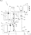
figure 1 et conformément à l'invention, on a représenté schématiquement une installation 1 de production d'ECS (ECS : eau chaude sanitaire) comprenant au moins : - un premier circuit primaire 2, délimité en trait mixte sur les figures, comportant un dispositif de production d'eau chaude 3, tel que par exemple une chaudière à gaz, et une pompe 4 permettant de faire circuler de l'eau chaude dans la partie primaire d'un premier échangeur thermique 5, nommé ci-après échangeur de chauffage 5,
- un deuxième circuit primaire 6, délimité en trait mixte sur les figures, comportant avantageusement un ballon de stockage 7 de l'eau provenant d'une boucle de récupération d'énergie 8, et une pompe 9 permettant de faire circuler l'eau provenant dudit ballon de stockage 7 vers la partie primaire d'un deuxième échangeur 10, nommé ci-après échangeur de préchauffage 10, et de boucler sur celui-ci,
- un circuit secondaire 11 comportant une boucle d'ECS 12 (ECS : eau chaude sanitaire), une pompe de bouclage 13 assurant la circulation de l'eau chaude sanitaire sur toute la boucle d'ECS 12, et une entrée d'eau froide 14, provenant classiquement du réseau d'eau de ville (EV), ladite eau froide passant, via des première, deuxième et troisième branches 15A, 15B et 15C, d'abord dans le circuit secondaire de l'échangeur de préchauffage 10 du deuxième circuit primaire 6 pour être préchauffée, puis dans le circuit secondaire de l'échangeur de chauffage 5 du premier circuit primaire 2 pour arriver à la température de départ réglementaire de l'ECS, avant d'être distribuée dans ladite boucle d'ECS 12 au point de distribution 16 par la troisième branche 15C du circuit secondaire 11.
- On désigne ici par "départ ECS" la zone située en aval du point de distribution 16 et par "retour ECS" la zone située en amont dudit point de distribution 16.
- Les première, deuxième et troisième branches 15A, 15B et 15C du circuit secondaire 11 sont respectivement disposées entre l'entrée d'eau froide 14 et l'entrée du circuit secondaire de l'échangeur de préchauffage 10, entre la sortie du circuit secondaire de l'échangeur de préchauffage 10 et l'entrée du circuit secondaire de l'échangeur de chauffage 5, et entre la sortie du circuit secondaire de l'échangeur de chauffage 5 et le point de distribution 16 sur la boucle d'ECS 12.
- Le premier circuit primaire 2 comporte, en outre, une vanne mélangeuse 17 à trois voies disposée entre la sortie du dispositif de production d'eau chaude 3 et l'entrée du circuit primaire de l'échangeur de chauffage 5, et gérant la puissance utile de l'échangeur de chauffage 5 en faisant recirculer en plus ou moins grande proportion une partie de l'eau provenant de la sortie du circuit primaire dudit échangeur de chauffage 5 sur lui-même, de sorte à faire varier la température de l'eau à l'entrée dudit circuit primaire.
- De même, on comprend bien que le deuxième circuit primaire 6 pourra également comporter, en outre, une vanne mélangeuse 35 (Cf.
figure 3 ) à trois voies disposée entre la sortie du ballon de stockage 7 et l'entrée du circuit primaire de l'échangeur de préchauffage 10, et gérant la puissance utile de dernier en faisant recirculer en plus ou moins grande proportion une partie de l'eau provenant de la sortie du circuit primaire dudit échangeur de préchauffage 10 sur lui-même, de sorte à faire varier la température de l'eau à l'entrée dudit circuit primaire. - La boucle de récupération d'énergie 8 permet de récupérer des calories pour chauffer l'ECS, partout où cela est possible et notamment au niveau des groupes froids (Climatisation, frigo ...) ou encore de panneaux solaires.
- L'Homme du Métier comprend bien que, dans le cas d'une boucle de récupération d'énergie 8 de grande longueur, par exemple une boucle de récupération d'énergie 8 mise en oeuvre au niveau des groupes de climatisation d'un grand bâtiment, le réseau de ladite boucle de récupération d'énergie 8 fera office de ballon de stockage 7 compte tenu du volume et de l'inertie du liquide contenu dans ledit réseau. Dans ce cas, la mise en place d'un ballon de stockage 7 à proprement parler dans le deuxième circuit primaire 6 n'est donc pas nécessaire et ledit deuxième circuit primaire 6 sera alimenté en eau par la boucle de récupération d'énergie 8.
- La pompe 9 du deuxième circuit primaire 6 est de préférence à débit variable pour adapter le fonctionnement du deuxième circuit primaire 6 au besoin en ECS.
- L'installation 1 de production d'ECS comporte également un module de recyclage 18 comprenant une pompe de recirculation 19 permettant de prélever, en aval dudit point de distribution 16, une partie de l'ECS de la boucle d'ECS 12 pour permettre une circulation permanente d'ECS dans le circuit secondaire de l'échangeur de chauffage 5 ou de l'échangeur de préchauffage 10, afin d'éviter l'entartrage de l'échangeur de chauffage 5 et de combattre les pertes thermiques sur la boucle ECS 12, mais éventuellement pour envoyer ponctuellement de l'eau à 60°C dans l'échangeur de préchauffage 10 pour assurer l'absence de développement de légionnelles dans celui-ci.
- Pour cela, le module de recyclage 18 comprend une vanne 20 trois voies disposée en aval de ladite pompe de recirculation 19 et permettant d'orienter le débit, provenant de ladite pompe de recirculation 19, vers le circuit secondaire de l'échangeur de chauffage 5, via une première branche 21 se raccordant à la deuxième branche 15B du circuit secondaire 11, ou bien vers le circuit secondaire de l'échangeur de préchauffage 10, via une deuxième branche 22 se raccordant à la première branche 15A du circuit secondaire 11.
- Le module de recyclage 18 est associé à une vanne d'équilibrage de débit 23 disposée entre l'entrée du circuit secondaire de l'échangeur de chauffage 5 et la première branche 21 dudit module de recyclage 18 et permettant de contrôler le débit de recirculation de l'ECS dans le circuit secondaire dudit échangeur de chauffage 5, afin d'assurer une vitesse minimale de circulation pour garantir le non-entartrage de ce dernier.
- Par ailleurs, l'installation 1 de production d'ECS, selon l'invention, comporte un fluxostat 24 ou tout autre dispositif disposé à l'aval de l'entrée d'eau froide 14 du circuit secondaire 11 et permettant de déterminer si on est en période de puisage, c'est-à-dire si de l'eau froide arrive par ladite entrée d'eau froide 14, afin d'optimiser le fonctionnement de l'installation 1 de production d'ECS, mais également de garantir la sécurité de cette dernière. En effet, si ledit fluxostat 24 ne détecte plus d'arrivée d'eau froide, il coupe la circulation de la pompe 9 du deuxième circuit primaire 6 pour éviter de réchauffer la boucle de récupération d'énergie 8. Il permet également l'ouverture de la vanne 20 trois voies du module de recyclage 18 pour envoyer de l'eau à 60 °C provenant de la boucle d'ECS 12 dans l'échangeur de préchauffage 10, selon une périodicité définie, afin de garantir le non-développement de légionnelles.
- De même, pour éviter les risques de brûlures des utilisateurs de l'ECS, l'installation 1 de production d'ECS comporte avantageusement un thermostat de sécurité 25 disposé en aval du point de distribution 16 sur la boucle d'ECS 12, ledit thermostat de sécurité 25 coupant la pompe 4 du premier circuit primaire 2 et fermant la vanne mélangeuse 17 dudit premier circuit primaire 2 en cas de surchauffe de l'ECS dans ladite boucle d'ECS 12.
- Par ailleurs, pour garantir un fonctionnement optimal, l'installation 1 de production d'ECS comprend avantageusement une régulation 26 permettant de gérer les fonctions suivantes :
- - ouverture de la vanne mélangeuse 17 dudit premier circuit primaire 2 afin de gérer la puissance utile de l'échangeur de chauffage 5 en fonction de la température de l'ECS dans la boucle d'ECS 12 donnée par une sonde de température départ ECS 27 disposée à l'aval du point de distribution 16 sur ladite boucle d'ECS 12,
- - gestion éventuelle du débit de la pompe 9 du deuxième circuit primaire 6 en fonction de la température de sortie de l'échangeur de préchauffage 10 donnée par une sonde de température 28 disposée à l'aval de la sortie du circuit secondaire dudit échangeur de préchauffage 10, de préférence entre cette dernière et la première branche 21 dudit module de recyclage 18,
- - gestion de l'énergie pour le réchauffage de la boucle d'ECS 12 (car ce réchauffage représente une très grosse part de la consommation énergétique dans les installations où il y a une boucle d'ECS 12) en agissant sur débit de la pompe 9 du deuxième circuit primaire 6 et sur l'orientation de la vanne 20 trois voies du module de recyclage 18 en fonction de la température de retour ECS dans la boucle d'ECS 12 donnée par une sonde de température 29 disposée à l'amont du point de distribution 16 et de la température à l'entrée du circuit primaire de l'échangeur de préchauffage 10 donnée par la sonde de température 30.
- Avec une installation 1 de production d'ECS ainsi configurée, trois modes de fonctionnement peuvent être envisagés.
- Ainsi, selon un premier mode de fonctionnement de l'installation 1 de production d'ECS correspondant à une période de puisage, l'eau froide arrive par l'entrée d'eau froide 14 du circuit secondaire 11, passe dans le circuit secondaire de l'échangeur de préchauffage 10 où elle est préchauffée jusqu'à une température intermédiaire, puis se mélange à l'ECS issue du module de recyclage 18. Ensuite, ce mélange va entrer dans le circuit secondaire de l'échangeur de chauffage 5 où il sera réchauffé, la vanne d'équilibrage de débit 23 assurant alors un débit constant dans ledit échangeur de chauffage 5. Enfin, à la sortie de l'échangeur de chauffage 5, l'eau chauffée rejoint le retour de la boucle d'ECS 12 pour former le départ ECS.
- Durant ce mode de fonctionnement, la régulation 26 assure une température de départ ECS réglementaire en agissant sur l'ouverture de la vanne mélangeuse 17 dudit premier circuit primaire 2 afin d'adapter aux besoins la puissance utile de l'échangeur de chauffage 5, le fluxostat 24 indique lui la présence d'un débit d'eau froide au niveau de l'entrée d'eau froide 14 du circuit secondaire 11, la pompe 9 du deuxième circuit primaire 6 fonctionne et fait circuler l'eau provenant dudit ballon de stockage 7 vers la partie primaire de l'échangeur de préchauffage 10, et la vanne 20 trois voies du module de recyclage 18 empêche que l'eau de ce dernier ne circule dans l'échangeur de préchauffage 10.
- De plus, selon un deuxième mode de fonctionnement de l'installation 1 de production d'ECS correspondant à une période de non-puisage, c'est-à-dire sans arrivée d'eau froide, avec une température de retour ECS supérieure à la température à l'entrée du circuit primaire de l'échangeur de préchauffage 10, le fluxostat 24 indique l'absence de débit, la pompe 9 du deuxième circuit primaire 6 s'arrête pour éviter de réchauffer la boucle de récupération d'énergie 8, la vanne 20 trois voies du module de recyclage 18 s'ouvre régulièrement pour envoyer l'eau dudit module de recyclage 18 dans l'échangeur de préchauffage 10 et ainsi éviter le développement de légionnelles.
- Durant ce mode de fonctionnement, l'eau dudit module de recyclage 18 passe ensuite également dans l'échangeur de chauffage 5 et la vanne mélangeuse 17 dudit premier circuit primaire 2 s'ouvre plus ou moins pour combattre les déperditions thermiques sur la boucle d'ECS 12.
- De plus, selon un troisième mode de fonctionnement de l'installation 1 de production d'ECS correspondant également à une période de non-puisage, mais avec une température de retour ECS inférieure à la température à l'entrée du circuit primaire de l'échangeur de préchauffage 10, le fluxostat 24 indique l'absence de débit, mais la pompe 9 du deuxième circuit primaire 6 est en marche et la vanne 20 trois voies du module de recyclage 18 oriente le débit de la boucle d'ECS 12 vers le circuit secondaire de l'échangeur de préchauffage 10 pour utiliser l'énergie de la boucle de récupération d'énergie 8 afin de réchauffer la boucle d'ECS 12 et ainsi économiser l'énergie provenant de la production d'eau chaude 3.
- On comprend bien que l'installation 1 de production d'ECS, selon l'invention, présente les avantages suivants :
- l'installation 1 utilise une boucle de récupération d'énergie 8 pour préchauffer de l'ECS et ainsi réaliser des économies significatives sur la consommation énergétique de ladite installation 1,
- chacun des échangeurs de chauffage 5 et/ou de préchauffage 10 est associé à un module de recyclage 18 qui permet de garantir leur non entartrage grâce à la circulation permanente à une vitesse minimale,
- le module de recyclage 18 permet également, pour assurer la fonction réchauffage de la boucle d'ECS 12, de ne faire passer qu'une partie de l'eau de la boucle d'ECS 12 dans les échangeurs de chauffage 5 et/ou de préchauffage 10 et de ne pas surcharger la pompe de bouclage 13 de la boucle d'ECS 12,
- l'intégration d'une vanne 20 trois voies dans le module de recyclage 18 permet de résoudre le risque de développement de légionnelles dans l'échangeur de préchauffage 10. En effet, en fonctionnement normal, si la température à l'intérieure de ce dernier est inférieure à 55°C, l'injection ponctuelle d'eau plus chaude (55°C ou plus) permet alors de stopper le développement de légionnelles.
- Par ailleurs, on comprend bien que l'eau circulant dans les premier et deuxième circuits primaires 2,6 pourra être remplacée par un fluide caloporteur d'un tout autre type sans sortir du cadre de la présente invention.
- En outre, les échangeurs de chauffage 5 et/ou de préchauffage 10 sont avantageusement du type échangeur thermique à spirale tel que, par exemple, celui décrit dans la demande de brevet
FR 2 874 080 - Enfin, l'Homme du Métier n'aura aucune difficulté à dimensionner et mettre en place sur l'installation 1 de production d'ECS des équipements tels que, par exemple, des clapets anti-retour, des évacuations ou encore des purges, nécessaires au bon fonctionnement de ladite installation 1 de production d'ECS.
- Selon une première variante de réalisation représentée à la
figure 2 , en cas d'eau très calcaire, l'installation 1 de production d'ECS comprend, en plus, un module de recyclage complémentaire 31 sur l'échangeur de préchauffage 10, afin d'assurer un débit de circulation minimum dans celui-ci. - Ce module de recyclage complémentaire 31 comprend une branche 32 reliant entre elles les première et deuxième branches 15A, 15B du circuit secondaire 11 respectivement en aval de la deuxième branche 22 et en amont de la première branche 21 du module de recyclage 18, une pompe de recirculation 33 disposée sur ladite branche 32 du module de recyclage complémentaire 31 et permettant de prélever de l'eau préchauffée en aval de l'échangeur de préchauffage 10 pour permettre une circulation permanente de cette eau dans le circuit secondaire dudit échangeur de préchauffage 10, afin d'éviter l'entartrage de ce dernier.
- En outre, le module de recyclage complémentaire 31 est associé de préférence à une vanne d'équilibrage de débit 34 disposée à l'entrée du circuit secondaire de l'échangeur de préchauffage 10 et permettant de contrôler le débit de recirculation dans le circuit secondaire dudit échangeur de préchauffage 10.
- Selon une autre variante de réalisation non représentée, la pompe 4 et la vanne mélangeuse 17 à trois voies du premier circuit primaire 2 sont respectivement remplacées par une pompe à débit variable et par une vanne deux voies, la régulation de la température de départ dans la boucle d'ECS 12 étant alors obtenue en jouant sur le débit de la pompe à débit variable et l'ouverture de la vanne deux voies. On peut également mettre une pompe à débit variable en conservant la vanne mélangeuse 17 à trois voies, mais il faut alors ajouter une vanne qui ferme la voie devenue inutile.
- Enfin, en référence à la
figure 3 et selon une dernière variante de réalisation, l'installation 1 de production d'ECS comprend, en plus, un module de choc thermique interne 36 permettant de faire circuler de l'eau provenant de la boucle d'ECS 12 dans le circuit secondaire de l'échangeur de chauffage 5 du premier circuit primaire 2, dans le circuit secondaire de l'échangeur de préchauffage 10 du deuxième circuit primaire 2, puis dans l'entrée d'eau froide, et enfin retour dans la boucle d'ECS 12. - Ce fonctionnement en sens inverse à celui décrit précédemment permet de chauffer l'eau dans l'échangeur de chauffage 5 pour élever la température de l'eau au niveau de l'échangeur de préchauffage 10, afin d'éviter le développement de légionnelles dans ce dernier. L'opération de choc thermique interne dans l'installation 1 de production d'ECS se déroulera avantageusement la nuit, période durant laquelle le besoin en ECS est quasiment nul.
- Ledit module de choc thermique interne 36 comprend avantageusement une pompe de circulation 37 et une vanne motorisée 38 disposées entre la première branche 15A du circuit secondaire 11 et la boucle d'ECS 12 en amont du point de distribution 16, et permettant d'orienter le débit provenant du circuit secondaire de l'échangeur de préchauffage 10 vers la boucle d'ECS 12 puis le circuit secondaire de l'échangeur de chauffage 5 pour réaliser le choc thermique de ces circuits.
- La régulation 26 permet alors de réguler la vitesse de rotation de ladite pompe de circulation 37, afin de réguler la température de l'eau au niveau de l'échangeur de préchauffage 10 et de la boucle d'ECS 12.
- Avec cette dernière variante de réalisation, on comprend alors bien que le module de recyclage 18 ne permet que d'éviter l'entartrage de l'échangeur de chauffage 5 et de combattre les pertes thermiques sur la boucle ECS 12. Pour cela, ledit module de recyclage 18 ne comprend alors qu'une pompe de recirculation 19 permettant de prélever, en aval dudit point de distribution 16, une partie de l'ECS de la boucle d'ECS 12 pour permettre une circulation permanente d'ECS dans le circuit secondaire de l'échangeur de chauffage 5
- On comprend bien que l'installation 1 de production d'ECS conforme à l'invention est de préférence utilisée pour des bâtiments du type, par exemple, cliniques ou hôpitaux. Toutefois, il est évident que cette installation 1 de production d'ECS peut être adaptée et utilisée pour d'autres types de bâtiments tels que, par exemple, des hôtels ou lycées.
- Enfin, il va de soi que les exemples de l'installation 1 de production d'ECS conformes à l'invention qui viennent d'être décrits ne sont que des illustrations particulières, en aucun cas limitatives de l'invention.
Claims (12)
- Installation (1) de production ECS comportant au moins :- un premier circuit primaire (2) comportant un dispositif de production d'eau chaude (3) et une pompe (4) permettant de faire circuler de l'eau chaude dans la partie primaire d'un premier échangeur thermique (5), nommé ci-après échangeur de chauffage (5),- un deuxième circuit primaire (6) alimenté en eau provenant d'une boucle de récupération d'énergie (8), et une pompe (9) permettant de faire circuler l'eau vers la partie primaire d'un deuxième échangeur (10), nommé ci-après échangeur de préchauffage (10), et de boucler sur celui-ci, et- un circuit secondaire (11) comportant une boucle d'ECS (12), une pompe de bouclage (13) assurant la circulation de l'eau chaude sanitaire sur toute la boucle d'ECS (12), et une entrée d'eau froide (14), ladite eau froide passant d'abord, via une première branche (15A), dans le circuit secondaire de l'échangeur de préchauffage (10) du deuxième circuit primaire (6) pour être préchauffée, puis, via une deuxième branche (15B), dans le circuit secondaire de l'échangeur de chauffage (5) du premier circuit primaire (2) pour arriver à la température réglementaire de l'ECS, avant d'être distribuée dans ladite boucle d'ECS (12) au point de distribution (16) par une troisième branche (15C) du circuit secondaire (11),ladite installation (1) étant caractérisée en ce qu'elle comporte un module de recyclage (18) permettant de prélever, en aval dudit point de distribution (16), une partie de l'ECS de la boucle d'ECS (12) pour permettre une circulation permanente d'ECS dans le circuit secondaire de l'échangeur de chauffage (5).
- Installation (1) selon la revendication 1 caractérisée en ce que le module de recyclage (18) permet également d'envoyer ponctuellement une partie de l'ECS de la boucle d'ECS (12) dans l'échangeur de préchauffage (10).
- Installation (1) selon les revendications 1 et 2 caractérisée en ce que le module de recyclage (18) comprend une pompe de recirculation (19) et une vanne (20) trois voies disposée en aval de ladite pompe de recirculation (19) et permettant d'orienter le débit provenant de cette dernière vers le circuit secondaire de l'échangeur de chauffage (5), via une première branche (21) se raccordant à la deuxième branche (15B) du circuit secondaire (11), ou bien vers le circuit secondaire de l'échangeur de préchauffage (10), via une deuxième branche (22) se raccordant à la première branche (15A) du circuit secondaire (11).
- Installation (1) selon la revendication 1 caractérisée en ce qu'elle comporte un module de choc thermique interne (36) permettant de faire circuler de l'eau provenant de la boucle d'ECS (12) dans le circuit secondaire de l'échangeur de chauffage (5) du premier circuit primaire (2), dans le circuit secondaire de l'échangeur de préchauffage (10) du deuxième circuit primaire (2), puis dans l'entrée d'eau froide, et enfin retour dans la boucle d'ECS (12).
- Installation (1) selon l'une quelconques des revendications 1 à 4 caractérisée en ce que le module de recyclage (18) est associé à une vanne d'équilibrage de débit (23) disposée entre l'entrée du circuit secondaire de l'échangeur de chauffage (5) et la première branche (21) dudit module de recyclage (18) et permettant de contrôler le débit de recirculation de l'ECS dans le circuit secondaire dudit échangeur de chauffage (5).
- Installation (1) selon l'une quelconque des revendications 1 à 5, caractérisée en ce qu'elle comporte un fluxostat (24), ou tout autre dispositif, disposé à l'aval de l'entrée d'eau froide (14) du circuit secondaire (11) et permettant de déterminer si de l'eau froide arrive par ladite entrée d'eau froide (14).
- Installation (1) selon l'une quelconque des revendications 1 à 6, caractérisée en ce que le premier circuit primaire (2) comporte une vanne mélangeuse (17) disposée entre la sortie du dispositif de production d'eau chaude (3) et l'entrée du circuit primaire de l'échangeur de chauffage (5), et gérant la puissance utile de l'échangeur de chauffage (5) en faisant recirculer en plus ou moins grande proportion une partie de l'eau provenant de la sortie du circuit primaire dudit échangeur de chauffage (5) sur lui-même, de sorte à faire varier la température de l'eau à l'entrée dudit circuit primaire.
- Installation (1) selon la revendication 7, caractérisée en ce qu'elle comporte un thermostat de sécurité (25) disposé en aval du point de distribution (16) sur la boucle d'ECS (12), ledit thermostat de sécurité (25) coupant la pompe (4) du premier circuit primaire (2) et fermant la vanne mélangeuse (17) dudit premier circuit primaire (2) en cas de surchauffe de l'ECS dans ladite boucle d'ECS (12).
- Installation (1) selon l'une quelconque des revendications 7 ou 8, caractérisée en ce qu'elle comporte une régulation (26) permettant de gérer au moins :- l'ouverture de la vanne mélangeuse (17) dudit premier circuit primaire (2) en fonction de la température de départ ECS dans la boucle d'ECS (12),- le débit de la pompe (9) du deuxième circuit primaire (6) en fonction de la température de sortie de l'échangeur de préchauffage (10).
- Installation (1) selon l'une quelconque des revendications 1 à 9 caractérisée en ce qu'elle comporte un module de recyclage complémentaire (31) sur l'échangeur de préchauffage (10), afin d'assurer un débit de circulation minimum dans celui-ci.
- Installation (1) selon la revendication 10 caractérisée en ce que le module de recyclage complémentaire (31) comprend une branche (32) reliant entre elles les première et deuxième branches (15A, 15B) du circuit secondaire (11) respectivement en aval de la deuxième branche (22) et en amont de la première branche (21) du module de recyclage (18), une pompe de recirculation (33) disposée sur ladite branche (32) du module de recyclage complémentaire (31) et permettant de prélever de l'eau préchauffée en aval de l'échangeur de préchauffage (10) pour permettre une circulation permanente de cette eau dans le circuit secondaire dudit échangeur de préchauffage (10), afin d'éviter l'entartrage de ce dernier.
- Installation (1) selon la revendication 11 caractérisée en ce que le module de recyclage complémentaire (31) est associé de préférence à une vanne d'équilibrage de débit (34) disposée à l'entrée du circuit secondaire de l'échangeur de préchauffage (10) et permettant de contrôler le débit de recirculation dans le circuit secondaire dudit échangeur de préchauffage (10).
Applications Claiming Priority (1)
| Application Number | Priority Date | Filing Date | Title |
|---|---|---|---|
| FR1757964 | 2017-08-29 |
Publications (2)
| Publication Number | Publication Date |
|---|---|
| EP3450859A1 true EP3450859A1 (fr) | 2019-03-06 |
| EP3450859B1 EP3450859B1 (fr) | 2020-09-30 |
Family
ID=60302266
Family Applications (1)
| Application Number | Title | Priority Date | Filing Date |
|---|---|---|---|
| EP18191538.0A Active EP3450859B1 (fr) | 2017-08-29 | 2018-08-29 | Installation de production d'eau chaude sanitaire integrant un prechauffage par energie recuperee |
Country Status (2)
| Country | Link |
|---|---|
| EP (1) | EP3450859B1 (fr) |
| DK (1) | DK3450859T3 (fr) |
Cited By (1)
| Publication number | Priority date | Publication date | Assignee | Title |
|---|---|---|---|---|
| FR3124582A1 (fr) * | 2021-06-29 | 2022-12-30 | Spirec | Installation de production d' e au c haude s anitaire |
Citations (4)
| Publication number | Priority date | Publication date | Assignee | Title |
|---|---|---|---|---|
| DE202012008863U1 (de) * | 2012-09-17 | 2012-11-15 | Robert Peter | Thermische Solaranlage als Kleinsttrinkwasserbevorratung mit Frischwasserstation |
| FR2976347A1 (fr) * | 2011-06-08 | 2012-12-14 | Charot Ets | Procede de regulation d'un systeme de production d'eau chaude, unite de regulation et systeme de production d'eau chaude |
| FR3019631A1 (fr) * | 2014-04-04 | 2015-10-09 | Charot Ets | Procede et unite de regulation d'une installation de production d'eau chaude sanitaire |
| FR3034849A1 (fr) * | 2015-04-13 | 2016-10-14 | Infiniti Energies | Kit modulaire de montage d'une installation de chauffage ou de climatisation et installation realisee a partir d'un tel kit |
-
2018
- 2018-08-29 EP EP18191538.0A patent/EP3450859B1/fr active Active
- 2018-08-29 DK DK18191538.0T patent/DK3450859T3/da active
Patent Citations (4)
| Publication number | Priority date | Publication date | Assignee | Title |
|---|---|---|---|---|
| FR2976347A1 (fr) * | 2011-06-08 | 2012-12-14 | Charot Ets | Procede de regulation d'un systeme de production d'eau chaude, unite de regulation et systeme de production d'eau chaude |
| DE202012008863U1 (de) * | 2012-09-17 | 2012-11-15 | Robert Peter | Thermische Solaranlage als Kleinsttrinkwasserbevorratung mit Frischwasserstation |
| FR3019631A1 (fr) * | 2014-04-04 | 2015-10-09 | Charot Ets | Procede et unite de regulation d'une installation de production d'eau chaude sanitaire |
| FR3034849A1 (fr) * | 2015-04-13 | 2016-10-14 | Infiniti Energies | Kit modulaire de montage d'une installation de chauffage ou de climatisation et installation realisee a partir d'un tel kit |
Cited By (2)
| Publication number | Priority date | Publication date | Assignee | Title |
|---|---|---|---|---|
| FR3124582A1 (fr) * | 2021-06-29 | 2022-12-30 | Spirec | Installation de production d' e au c haude s anitaire |
| EP4113015A1 (fr) | 2021-06-29 | 2023-01-04 | Spirec | Installation de production d'eau chaude sanitaire |
Also Published As
| Publication number | Publication date |
|---|---|
| EP3450859B1 (fr) | 2020-09-30 |
| DK3450859T3 (da) | 2021-01-04 |
Similar Documents
| Publication | Publication Date | Title |
|---|---|---|
| TWI377325B (fr) | ||
| EP2312227B1 (fr) | Installation de ventilation mécanique contrôlée de type double flux thermodynamique réversible avec production d'eau chaude sanitaire | |
| CN107367065A (zh) | 一种利用水泵防冻的燃气热水器和方法 | |
| EP3353473A1 (fr) | Dispositif de production d'eau chaude sanitaire par récupération de chaleur des eaux usées, une installation et un procédé de production associé | |
| EP3450859B1 (fr) | Installation de production d'eau chaude sanitaire integrant un prechauffage par energie recuperee | |
| FR2963087A1 (fr) | Appareil de production d'eau chaude sanitaire et procede de fonctionnement d'un tel appareil | |
| EP3671051B1 (fr) | Procédé de contrôle du retour de bouclage sanitaire pour un système de production d'eau chaude sanitaire | |
| WO2012062992A1 (fr) | Chaudière à coefficient de performance élevé | |
| JP6055356B2 (ja) | 熱源装置 | |
| FR2813117A1 (fr) | Procede et installation de chauffage a partir de l'energie solaire | |
| FR3031575A1 (fr) | Module de transfert thermique avec regulation associee pour systeme thermodynamique de production d'eau chaude sanitaire | |
| CH500446A (fr) | Installation pour la production d'eau chaude à usage domestique | |
| JP6197452B2 (ja) | 給湯システム | |
| EP2133629A1 (fr) | Dispositif de couplage entre une pompe à chaleur et une chaudiére à fuel ou à gaz | |
| WO2010043829A2 (fr) | Pompe a chaleur | |
| JP5901312B2 (ja) | 貯湯システム | |
| WO2013093246A1 (fr) | Procédé de gestion d'un système de pompe à chaleur, système de pompe à chaleur, et installation de chauffage comprenant un tel système | |
| EP4113015A1 (fr) | Installation de production d'eau chaude sanitaire | |
| FR2999684A1 (fr) | Dispositif de preparation d'eau chaude sanitaire | |
| JP3699402B2 (ja) | 湯水混合ユニット | |
| FR2909749A1 (fr) | Dispositif de couplage entre une pompe a chaleur et une chaudiere a fuel ou a gaz. | |
| JP2004347196A (ja) | 給湯システム | |
| EP2224176B1 (fr) | Installation de chauffe-eau ameliorée | |
| FR3012873A1 (fr) | Methode et dispositif de transfert d'energie thermique en milieu urbain | |
| FR2935781A1 (fr) | Procede de regulation d'une installation de chauffage comportant au moins une pompe a chaleur et un moyen de chauffage complementaire |
Legal Events
| Date | Code | Title | Description |
|---|---|---|---|
| PUAI | Public reference made under article 153(3) epc to a published international application that has entered the european phase |
Free format text: ORIGINAL CODE: 0009012 |
|
| STAA | Information on the status of an ep patent application or granted ep patent |
Free format text: STATUS: THE APPLICATION HAS BEEN PUBLISHED |
|
| AK | Designated contracting states |
Kind code of ref document: A1 Designated state(s): AL AT BE BG CH CY CZ DE DK EE ES FI FR GB GR HR HU IE IS IT LI LT LU LV MC MK MT NL NO PL PT RO RS SE SI SK SM TR |
|
| AX | Request for extension of the european patent |
Extension state: BA ME |
|
| STAA | Information on the status of an ep patent application or granted ep patent |
Free format text: STATUS: REQUEST FOR EXAMINATION WAS MADE |
|
| 17P | Request for examination filed |
Effective date: 20190906 |
|
| RAP1 | Party data changed (applicant data changed or rights of an application transferred) |
Owner name: SPIREC |
|
| GRAP | Despatch of communication of intention to grant a patent |
Free format text: ORIGINAL CODE: EPIDOSNIGR1 |
|
| STAA | Information on the status of an ep patent application or granted ep patent |
Free format text: STATUS: GRANT OF PATENT IS INTENDED |
|
| RIC1 | Information provided on ipc code assigned before grant |
Ipc: F24D 17/00 20060101AFI20200319BHEP Ipc: F24D 19/10 20060101ALI20200319BHEP |
|
| INTG | Intention to grant announced |
Effective date: 20200406 |
|
| GRAS | Grant fee paid |
Free format text: ORIGINAL CODE: EPIDOSNIGR3 |
|
| GRAA | (expected) grant |
Free format text: ORIGINAL CODE: 0009210 |
|
| STAA | Information on the status of an ep patent application or granted ep patent |
Free format text: STATUS: THE PATENT HAS BEEN GRANTED |
|
| AK | Designated contracting states |
Kind code of ref document: B1 Designated state(s): AL AT BE BG CH CY CZ DE DK EE ES FI FR GB GR HR HU IE IS IT LI LT LU LV MC MK MT NL NO PL PT RO RS SE SI SK SM TR |
|
| REG | Reference to a national code |
Ref country code: CH Ref legal event code: EP Ref country code: GB Ref legal event code: FG4D Free format text: NOT ENGLISH |
|
| REG | Reference to a national code |
Ref country code: AT Ref legal event code: REF Ref document number: 1319180 Country of ref document: AT Kind code of ref document: T Effective date: 20201015 |
|
| REG | Reference to a national code |
Ref country code: DE Ref legal event code: R096 Ref document number: 602018008261 Country of ref document: DE |
|
| REG | Reference to a national code |
Ref country code: IE Ref legal event code: FG4D Free format text: LANGUAGE OF EP DOCUMENT: FRENCH |
|
| REG | Reference to a national code |
Ref country code: DK Ref legal event code: T3 Effective date: 20201222 |
|
| REG | Reference to a national code |
Ref country code: SE Ref legal event code: TRGR |
|
| PG25 | Lapsed in a contracting state [announced via postgrant information from national office to epo] |
Ref country code: FI Free format text: LAPSE BECAUSE OF FAILURE TO SUBMIT A TRANSLATION OF THE DESCRIPTION OR TO PAY THE FEE WITHIN THE PRESCRIBED TIME-LIMIT Effective date: 20200930 Ref country code: HR Free format text: LAPSE BECAUSE OF FAILURE TO SUBMIT A TRANSLATION OF THE DESCRIPTION OR TO PAY THE FEE WITHIN THE PRESCRIBED TIME-LIMIT Effective date: 20200930 Ref country code: BG Free format text: LAPSE BECAUSE OF FAILURE TO SUBMIT A TRANSLATION OF THE DESCRIPTION OR TO PAY THE FEE WITHIN THE PRESCRIBED TIME-LIMIT Effective date: 20201230 Ref country code: GR Free format text: LAPSE BECAUSE OF FAILURE TO SUBMIT A TRANSLATION OF THE DESCRIPTION OR TO PAY THE FEE WITHIN THE PRESCRIBED TIME-LIMIT Effective date: 20201231 Ref country code: NO Free format text: LAPSE BECAUSE OF FAILURE TO SUBMIT A TRANSLATION OF THE DESCRIPTION OR TO PAY THE FEE WITHIN THE PRESCRIBED TIME-LIMIT Effective date: 20201230 |
|
| REG | Reference to a national code |
Ref country code: AT Ref legal event code: MK05 Ref document number: 1319180 Country of ref document: AT Kind code of ref document: T Effective date: 20200930 |
|
| REG | Reference to a national code |
Ref country code: NL Ref legal event code: FP |
|
| PG25 | Lapsed in a contracting state [announced via postgrant information from national office to epo] |
Ref country code: RS Free format text: LAPSE BECAUSE OF FAILURE TO SUBMIT A TRANSLATION OF THE DESCRIPTION OR TO PAY THE FEE WITHIN THE PRESCRIBED TIME-LIMIT Effective date: 20200930 Ref country code: LV Free format text: LAPSE BECAUSE OF FAILURE TO SUBMIT A TRANSLATION OF THE DESCRIPTION OR TO PAY THE FEE WITHIN THE PRESCRIBED TIME-LIMIT Effective date: 20200930 |
|
| REG | Reference to a national code |
Ref country code: LT Ref legal event code: MG4D |
|
| PG25 | Lapsed in a contracting state [announced via postgrant information from national office to epo] |
Ref country code: LT Free format text: LAPSE BECAUSE OF FAILURE TO SUBMIT A TRANSLATION OF THE DESCRIPTION OR TO PAY THE FEE WITHIN THE PRESCRIBED TIME-LIMIT Effective date: 20200930 Ref country code: SM Free format text: LAPSE BECAUSE OF FAILURE TO SUBMIT A TRANSLATION OF THE DESCRIPTION OR TO PAY THE FEE WITHIN THE PRESCRIBED TIME-LIMIT Effective date: 20200930 Ref country code: RO Free format text: LAPSE BECAUSE OF FAILURE TO SUBMIT A TRANSLATION OF THE DESCRIPTION OR TO PAY THE FEE WITHIN THE PRESCRIBED TIME-LIMIT Effective date: 20200930 Ref country code: PT Free format text: LAPSE BECAUSE OF FAILURE TO SUBMIT A TRANSLATION OF THE DESCRIPTION OR TO PAY THE FEE WITHIN THE PRESCRIBED TIME-LIMIT Effective date: 20210201 Ref country code: CZ Free format text: LAPSE BECAUSE OF FAILURE TO SUBMIT A TRANSLATION OF THE DESCRIPTION OR TO PAY THE FEE WITHIN THE PRESCRIBED TIME-LIMIT Effective date: 20200930 Ref country code: EE Free format text: LAPSE BECAUSE OF FAILURE TO SUBMIT A TRANSLATION OF THE DESCRIPTION OR TO PAY THE FEE WITHIN THE PRESCRIBED TIME-LIMIT Effective date: 20200930 |
|
| PG25 | Lapsed in a contracting state [announced via postgrant information from national office to epo] |
Ref country code: PL Free format text: LAPSE BECAUSE OF FAILURE TO SUBMIT A TRANSLATION OF THE DESCRIPTION OR TO PAY THE FEE WITHIN THE PRESCRIBED TIME-LIMIT Effective date: 20200930 Ref country code: IS Free format text: LAPSE BECAUSE OF FAILURE TO SUBMIT A TRANSLATION OF THE DESCRIPTION OR TO PAY THE FEE WITHIN THE PRESCRIBED TIME-LIMIT Effective date: 20210130 Ref country code: AL Free format text: LAPSE BECAUSE OF FAILURE TO SUBMIT A TRANSLATION OF THE DESCRIPTION OR TO PAY THE FEE WITHIN THE PRESCRIBED TIME-LIMIT Effective date: 20200930 Ref country code: AT Free format text: LAPSE BECAUSE OF FAILURE TO SUBMIT A TRANSLATION OF THE DESCRIPTION OR TO PAY THE FEE WITHIN THE PRESCRIBED TIME-LIMIT Effective date: 20200930 Ref country code: ES Free format text: LAPSE BECAUSE OF FAILURE TO SUBMIT A TRANSLATION OF THE DESCRIPTION OR TO PAY THE FEE WITHIN THE PRESCRIBED TIME-LIMIT Effective date: 20200930 |
|
| PG25 | Lapsed in a contracting state [announced via postgrant information from national office to epo] |
Ref country code: SK Free format text: LAPSE BECAUSE OF FAILURE TO SUBMIT A TRANSLATION OF THE DESCRIPTION OR TO PAY THE FEE WITHIN THE PRESCRIBED TIME-LIMIT Effective date: 20200930 |
|
| REG | Reference to a national code |
Ref country code: DE Ref legal event code: R097 Ref document number: 602018008261 Country of ref document: DE |
|
| PLBE | No opposition filed within time limit |
Free format text: ORIGINAL CODE: 0009261 |
|
| STAA | Information on the status of an ep patent application or granted ep patent |
Free format text: STATUS: NO OPPOSITION FILED WITHIN TIME LIMIT |
|
| 26N | No opposition filed |
Effective date: 20210701 |
|
| PG25 | Lapsed in a contracting state [announced via postgrant information from national office to epo] |
Ref country code: IT Free format text: LAPSE BECAUSE OF FAILURE TO SUBMIT A TRANSLATION OF THE DESCRIPTION OR TO PAY THE FEE WITHIN THE PRESCRIBED TIME-LIMIT Effective date: 20200930 |
|
| PG25 | Lapsed in a contracting state [announced via postgrant information from national office to epo] |
Ref country code: SI Free format text: LAPSE BECAUSE OF FAILURE TO SUBMIT A TRANSLATION OF THE DESCRIPTION OR TO PAY THE FEE WITHIN THE PRESCRIBED TIME-LIMIT Effective date: 20200930 |
|
| REG | Reference to a national code |
Ref country code: SE Ref legal event code: EUG |
|
| PG25 | Lapsed in a contracting state [announced via postgrant information from national office to epo] |
Ref country code: IS Free format text: LAPSE BECAUSE OF FAILURE TO SUBMIT A TRANSLATION OF THE DESCRIPTION OR TO PAY THE FEE WITHIN THE PRESCRIBED TIME-LIMIT Effective date: 20210130 Ref country code: SE Free format text: LAPSE BECAUSE OF NON-PAYMENT OF DUE FEES Effective date: 20210830 |
|
| PG25 | Lapsed in a contracting state [announced via postgrant information from national office to epo] |
Ref country code: CY Free format text: LAPSE BECAUSE OF FAILURE TO SUBMIT A TRANSLATION OF THE DESCRIPTION OR TO PAY THE FEE WITHIN THE PRESCRIBED TIME-LIMIT Effective date: 20200930 |
|
| PG25 | Lapsed in a contracting state [announced via postgrant information from national office to epo] |
Ref country code: HU Free format text: LAPSE BECAUSE OF FAILURE TO SUBMIT A TRANSLATION OF THE DESCRIPTION OR TO PAY THE FEE WITHIN THE PRESCRIBED TIME-LIMIT; INVALID AB INITIO Effective date: 20180829 |
|
| PGFP | Annual fee paid to national office [announced via postgrant information from national office to epo] |
Ref country code: NL Payment date: 20230829 Year of fee payment: 6 Ref country code: LU Payment date: 20230829 Year of fee payment: 6 |
|
| PGFP | Annual fee paid to national office [announced via postgrant information from national office to epo] |
Ref country code: MC Payment date: 20230830 Year of fee payment: 6 Ref country code: IE Payment date: 20230829 Year of fee payment: 6 Ref country code: GB Payment date: 20230830 Year of fee payment: 6 Ref country code: CH Payment date: 20230902 Year of fee payment: 6 |
|
| PGFP | Annual fee paid to national office [announced via postgrant information from national office to epo] |
Ref country code: FR Payment date: 20230828 Year of fee payment: 6 Ref country code: DK Payment date: 20230829 Year of fee payment: 6 Ref country code: DE Payment date: 20230829 Year of fee payment: 6 Ref country code: BE Payment date: 20230829 Year of fee payment: 6 |
|
| PG25 | Lapsed in a contracting state [announced via postgrant information from national office to epo] |
Ref country code: MK Free format text: LAPSE BECAUSE OF FAILURE TO SUBMIT A TRANSLATION OF THE DESCRIPTION OR TO PAY THE FEE WITHIN THE PRESCRIBED TIME-LIMIT Effective date: 20200930 |