EP3450848B1 - Method for controlling a combustion apparatus and control device - Google Patents
Method for controlling a combustion apparatus and control device Download PDFInfo
- Publication number
- EP3450848B1 EP3450848B1 EP17189064.3A EP17189064A EP3450848B1 EP 3450848 B1 EP3450848 B1 EP 3450848B1 EP 17189064 A EP17189064 A EP 17189064A EP 3450848 B1 EP3450848 B1 EP 3450848B1
- Authority
- EP
- European Patent Office
- Prior art keywords
- signal
- time
- combustion
- determining
- time series
- Prior art date
- Legal status (The legal status is an assumption and is not a legal conclusion. Google has not performed a legal analysis and makes no representation as to the accuracy of the status listed.)
- Active
Links
- 238000002485 combustion reaction Methods 0.000 title claims description 111
- 238000000034 method Methods 0.000 title claims description 36
- 230000000739 chaotic effect Effects 0.000 claims description 22
- 230000000737 periodic effect Effects 0.000 claims description 21
- 230000036962 time dependent Effects 0.000 claims description 17
- 230000008859 change Effects 0.000 claims description 9
- 239000007800 oxidant agent Substances 0.000 claims description 7
- 239000012528 membrane Substances 0.000 claims description 6
- 230000005855 radiation Effects 0.000 claims description 5
- 229920006395 saturated elastomer Polymers 0.000 claims description 5
- 125000004122 cyclic group Chemical group 0.000 claims description 4
- 238000001914 filtration Methods 0.000 claims description 2
- 238000009738 saturating Methods 0.000 claims description 2
- 230000010355 oscillation Effects 0.000 description 15
- 230000006870 function Effects 0.000 description 14
- 230000008878 coupling Effects 0.000 description 8
- 238000010168 coupling process Methods 0.000 description 8
- 238000005859 coupling reaction Methods 0.000 description 8
- 238000001228 spectrum Methods 0.000 description 6
- 238000010586 diagram Methods 0.000 description 5
- 239000007789 gas Substances 0.000 description 4
- 230000006835 compression Effects 0.000 description 3
- 238000007906 compression Methods 0.000 description 3
- 238000013016 damping Methods 0.000 description 3
- 239000000446 fuel Substances 0.000 description 3
- 231100001261 hazardous Toxicity 0.000 description 3
- 230000007774 longterm Effects 0.000 description 3
- 230000003993 interaction Effects 0.000 description 2
- MWUXSHHQAYIFBG-UHFFFAOYSA-N nitrogen oxide Inorganic materials O=[N] MWUXSHHQAYIFBG-UHFFFAOYSA-N 0.000 description 2
- 230000001590 oxidative effect Effects 0.000 description 2
- 239000000376 reactant Substances 0.000 description 2
- 239000000126 substance Substances 0.000 description 2
- 230000002123 temporal effect Effects 0.000 description 2
- 238000011144 upstream manufacturing Methods 0.000 description 2
- GQPLMRYTRLFLPF-UHFFFAOYSA-N Nitrous Oxide Chemical compound [O-][N+]#N GQPLMRYTRLFLPF-UHFFFAOYSA-N 0.000 description 1
- 229910000831 Steel Inorganic materials 0.000 description 1
- 230000002411 adverse Effects 0.000 description 1
- 239000003570 air Substances 0.000 description 1
- 230000007423 decrease Effects 0.000 description 1
- 230000003111 delayed effect Effects 0.000 description 1
- 230000006866 deterioration Effects 0.000 description 1
- 239000006185 dispersion Substances 0.000 description 1
- 230000000694 effects Effects 0.000 description 1
- 230000001747 exhibiting effect Effects 0.000 description 1
- 238000012886 linear function Methods 0.000 description 1
- 238000004519 manufacturing process Methods 0.000 description 1
- 238000005259 measurement Methods 0.000 description 1
- 230000007246 mechanism Effects 0.000 description 1
- 239000000203 mixture Substances 0.000 description 1
- 230000004048 modification Effects 0.000 description 1
- 238000012986 modification Methods 0.000 description 1
- 238000005457 optimization Methods 0.000 description 1
- 230000003534 oscillatory effect Effects 0.000 description 1
- 230000010363 phase shift Effects 0.000 description 1
- 230000008569 process Effects 0.000 description 1
- 230000004044 response Effects 0.000 description 1
- 238000012163 sequencing technique Methods 0.000 description 1
- 239000010959 steel Substances 0.000 description 1
- 238000003860 storage Methods 0.000 description 1
- 230000001629 suppression Effects 0.000 description 1
Images

Classifications
-
- F—MECHANICAL ENGINEERING; LIGHTING; HEATING; WEAPONS; BLASTING
- F02—COMBUSTION ENGINES; HOT-GAS OR COMBUSTION-PRODUCT ENGINE PLANTS
- F02D—CONTROLLING COMBUSTION ENGINES
- F02D41/00—Electrical control of supply of combustible mixture or its constituents
- F02D41/02—Circuit arrangements for generating control signals
- F02D41/14—Introducing closed-loop corrections
- F02D41/1401—Introducing closed-loop corrections characterised by the control or regulation method
- F02D41/1402—Adaptive control
-
- F—MECHANICAL ENGINEERING; LIGHTING; HEATING; WEAPONS; BLASTING
- F23—COMBUSTION APPARATUS; COMBUSTION PROCESSES
- F23N—REGULATING OR CONTROLLING COMBUSTION
- F23N5/00—Systems for controlling combustion
- F23N5/20—Systems for controlling combustion with a time programme acting through electrical means, e.g. using time-delay relays
- F23N5/203—Systems for controlling combustion with a time programme acting through electrical means, e.g. using time-delay relays using electronic means
-
- F—MECHANICAL ENGINEERING; LIGHTING; HEATING; WEAPONS; BLASTING
- F23—COMBUSTION APPARATUS; COMBUSTION PROCESSES
- F23N—REGULATING OR CONTROLLING COMBUSTION
- F23N5/00—Systems for controlling combustion
- F23N5/02—Systems for controlling combustion using devices responsive to thermal changes or to thermal expansion of a medium
- F23N5/08—Systems for controlling combustion using devices responsive to thermal changes or to thermal expansion of a medium using light-sensitive elements
-
- F—MECHANICAL ENGINEERING; LIGHTING; HEATING; WEAPONS; BLASTING
- F23—COMBUSTION APPARATUS; COMBUSTION PROCESSES
- F23N—REGULATING OR CONTROLLING COMBUSTION
- F23N5/00—Systems for controlling combustion
- F23N5/16—Systems for controlling combustion using noise-sensitive detectors
-
- F—MECHANICAL ENGINEERING; LIGHTING; HEATING; WEAPONS; BLASTING
- F23—COMBUSTION APPARATUS; COMBUSTION PROCESSES
- F23N—REGULATING OR CONTROLLING COMBUSTION
- F23N5/00—Systems for controlling combustion
- F23N5/24—Preventing development of abnormal or undesired conditions, i.e. safety arrangements
- F23N5/242—Preventing development of abnormal or undesired conditions, i.e. safety arrangements using electronic means
-
- F—MECHANICAL ENGINEERING; LIGHTING; HEATING; WEAPONS; BLASTING
- F02—COMBUSTION ENGINES; HOT-GAS OR COMBUSTION-PRODUCT ENGINE PLANTS
- F02D—CONTROLLING COMBUSTION ENGINES
- F02D41/00—Electrical control of supply of combustible mixture or its constituents
- F02D41/02—Circuit arrangements for generating control signals
- F02D41/14—Introducing closed-loop corrections
- F02D41/1401—Introducing closed-loop corrections characterised by the control or regulation method
- F02D2041/1413—Controller structures or design
- F02D2041/1426—Controller structures or design taking into account control stability
-
- F—MECHANICAL ENGINEERING; LIGHTING; HEATING; WEAPONS; BLASTING
- F02—COMBUSTION ENGINES; HOT-GAS OR COMBUSTION-PRODUCT ENGINE PLANTS
- F02D—CONTROLLING COMBUSTION ENGINES
- F02D41/00—Electrical control of supply of combustible mixture or its constituents
- F02D41/02—Circuit arrangements for generating control signals
- F02D41/14—Introducing closed-loop corrections
- F02D41/1401—Introducing closed-loop corrections characterised by the control or regulation method
- F02D2041/1413—Controller structures or design
- F02D2041/143—Controller structures or design the control loop including a non-linear model or compensator
-
- F—MECHANICAL ENGINEERING; LIGHTING; HEATING; WEAPONS; BLASTING
- F23—COMBUSTION APPARATUS; COMBUSTION PROCESSES
- F23N—REGULATING OR CONTROLLING COMBUSTION
- F23N2223/00—Signal processing; Details thereof
- F23N2223/06—Sampling
-
- F—MECHANICAL ENGINEERING; LIGHTING; HEATING; WEAPONS; BLASTING
- F23—COMBUSTION APPARATUS; COMBUSTION PROCESSES
- F23N—REGULATING OR CONTROLLING COMBUSTION
- F23N2223/00—Signal processing; Details thereof
- F23N2223/10—Correlation
-
- F—MECHANICAL ENGINEERING; LIGHTING; HEATING; WEAPONS; BLASTING
- F23—COMBUSTION APPARATUS; COMBUSTION PROCESSES
- F23N—REGULATING OR CONTROLLING COMBUSTION
- F23N2225/00—Measuring
- F23N2225/04—Measuring pressure
-
- F—MECHANICAL ENGINEERING; LIGHTING; HEATING; WEAPONS; BLASTING
- F23—COMBUSTION APPARATUS; COMBUSTION PROCESSES
- F23N—REGULATING OR CONTROLLING COMBUSTION
- F23N2225/00—Measuring
- F23N2225/08—Measuring temperature
-
- F—MECHANICAL ENGINEERING; LIGHTING; HEATING; WEAPONS; BLASTING
- F23—COMBUSTION APPARATUS; COMBUSTION PROCESSES
- F23N—REGULATING OR CONTROLLING COMBUSTION
- F23N2241/00—Applications
- F23N2241/20—Gas turbines
Definitions
- Embodiments of the present invention relate to methods and control devices for physical and chemical apparatuses in which undesired oscillations may emerge spontaneously due to a feedback coupling, in particular to methods and control devices for a combustion apparatus.
- thermoacoustic coupling may occur in apparatuses (systems) such as gas turbine engines, furnaces, boilers, rocket engines, and afterburners that are driven by confined combustion.
- Thermoacoustic coupling may lead to a self-excited instability, (also known as combustion instability, rumble, and reheat buzz), which appears spontaneously in the form of large amplitude pressure and heat release rate oscillations.
- the instability may be hazardous for the apparatus.
- thermoacoustic instabilities it is often desirable to suppress the thermoacoustic instabilities.
- Previously used control attempts (implicitly) assumed that the thermoacoustic instabilities correspond to limit cycle oscillations, possibly with harmonics. Therefore, the fact that the thermoacoustic system can undergo bifurcations to more complex nonlinear states, such as chaos is not taken into account. In fact, it is even possible that at onset of the instability when the system has just crossed the stability boundary, thermoacoustic oscillations correspond to a chaotic state. Previous methods will fail outright in such a scenario.
- WO 85/03761 A1 discloses a method for controlling a combustion apparatus comprising a combustion state in which a temperature related to the combustion state reflects a chaotic behaviour, the method comprising measuring the temperature and carrying out a cyclic measurement of the temperature, determining a time dependent periodically variable sequencing signal using a frequency of a desired periodic combustion state of the combustion apparatus, combining the signals for determining a control signal, and using the control signal to influence the combustion apparatus by applying the control signal to a valve.
- the method includes measuring the parameter and determining a time series of the parameter.
- a variable time delay is changed, the time series is shifted by the variable time delay for determining a time-shifted signal, and a difference between the time-shifted signal and the time series is formed for determining a time dependent first signal until a norm of the difference between the time-shifted signal and the time series is lowest.
- a time dependent second signal different to the first signal is determined. Determining the time dependent second signal includes at least one of using a frequency of a desired periodic combustion state of the combustion apparatus, and shifting the time series by a set time delay.
- the first signal and the second signal are combined for determining a control signal.
- the control signal is used to influence the combustion apparatus.
- the difference between the time-shifted signal and the time series is also referred to as (time dependent) difference signal.
- combustion state in which the parameter related to the combustion state reflects a chaotic behavior is also referred to as chaotic combustion state and chaotic state of combustion, respectively.
- the term "chaotic state” as used in this specification intends to describe a state of a system or apparatus exhibiting an aperiodic long-term behaviour with sensitive dependence on initial conditions.
- the term "aperiodic long-term behaviour” intends to describe that in the asymptotic dynamics the system or apparatus does not correspond to a fixed-point, a periodic orbit or a quasi-periodic behaviour.
- the system or apparatus may be (describable as) a non-linear deterministic system or apparatus, i.e. a system or apparatus in which the chaotic behaviour is not due to noisy or random forces, but rather due to the nonlinearity present in the system or apparatus, in particular a nonlinearity in the feedback coupling mechanism associated with thermoacoustic instability in the system or apparatus.
- sensitive dependence on initial conditions intends to describe that nearby initial conditions separate exponentially fast while the system or apparatus evolves in time.
- the method allows transferring the combustion apparatus from the chaotic combustion state into a periodic combustion state, and subsequently into a periodic state with a dominant frequency (of the parameter) shifted to the frequency of the desired oscillating state and/or a periodic state with reduced amplitude of oscillations compared to the initial state. Accordingly, hazardous instabilities of the combustion apparatus such as high mechanical loading can reliably be dampened or even suppressed. Further, other undesired effects that may occur in the chaotic state such as deterioration of exhaust values and exceeding of desired exhaust values, respectively, e.g. increased nitrogen oxide(s) (NO x ), may be avoided.
- NO x nitrogen oxide(s)
- the first signal is effective to drive the combustion apparatus from a chaotic combustion state into a periodic combustion state.
- Using a desired main frequency of the desired periodic combustion state for determining the second signal and, thus, the control signal of the combustion apparatus, allows driving the combustion state towards, more typically into the desired combustion state. Further, a damping of the amplitude of the oscillation of the parameter may be achieved.
- the set time delay ( ⁇ set ) determines the shift in the dominant frequency of the periodic combustion state.
- Whether an open-loop control based on the desired main frequency or a feed-back control using a set time delay ( ⁇ set ) is more efficient to drive the apparatus into the desired periodic combustion state may depend on the details of the apparatus.
- variable time delay ( ⁇ art ) for the first signal S 1 and the set time delay ( ⁇ set ) for the second signal S 2 will typically be of the order of the time-period of the acoustic resonance frequency of the apparatus.
- the set time delay ( ⁇ set ) may be determined based on mechanical, geometrical, chemical and/or thermodynamic properties of the combustion apparatus. For example, the set time delay may be determined based on the acoustic resonance frequency of the combustion apparatus.
- the parameter may be any variable or observable that participates in the chaotic behaviour of the thermoacoustic oscillations.
- thermoacoustic oscillations intends to describe fluctuations and/or oscillations in a medium such as a gas which are due to a feedback interaction between an acoustic field in the medium, and temporal fluctuations in the heat release rate from combustion (or from a flame).
- the term “thermoacoustic oscillations” shall embrace oscillations in a flame (and associated quantities such as the unsteady heat release rate from the flame), and in an acoustic field within an apparatus at least partly enclosing the flame, typically within a combustion chamber of the apparatus, that emerge spontaneously due to a constructive feedback interaction between the flame and the acoustic field.
- the parameter may be a pressure in the apparatus, a temperature in the apparatus, a density in the apparatus, a radiation power of the combustion (typically a chemiluminescence from the flame) or a parameter related to one or more of the pressure, the temperature, the density and the radiation power.
- the parameter is the pressure.
- the pressure in the apparatus can reliably be measured with high temporal resolution.
- the measured values of the parameter are typically high-pass filtered. Accordingly, a (long-term) drift of the parameter is eliminated.
- the norm of the difference signal may be determined as an integral or a sum of (all) absolute amplitude values of the difference signal, e.g. as sum absolute pressure values.
- a root mean square value of the amplitude values of the difference signal may be determined as norm of the difference signal.
- variable time delay is typically varied starting from a value close the inverse of the dominant frequency in the oscillations until the norm of the difference signal reaches a minimum value, typically a global minimum value.
- the amplitude of the first signal is small, typically close to zero if the apparatus is in a periodic state.
- the proposed controlling does not require analyzing the state of the apparatus and/or switching on and off the first signal.
- determining the time dependent first signal includes determining a difference between a first subset of the time series and a second subset of the time series, wherein the variable time delay between the first second subset and the second subset is determined so that so that a norm of the difference signal determined as difference between the first subset and the second subset is lowest.
- Combining the first signal and the second signal is typically achieved by adding the first signal and the second signal or by forming a weighted sum of the first signal and the second signal.
- Using the control signal may include feeding the input signal to an actuator coupled with the combustion apparatus.
- Using the control signal may also include converting the control signal to an input signal for the actuator and feeding the input signal to the actuator.
- the input signal may be a time dependent voltage.
- control signal or the input signal may be saturated prior to feeding to the actuator.
- Converting and/or saturating the control signal may also already be achieved during combining the first signal and the second signal using an appropriate function (F).
- the actuator is typically configured to convert the input signal, which is in the following also referred to as primary control signal into a secondary control signal suitable to influence the combustion apparatus.
- the primary control signal and the secondary control signal may be used to modulate a fuel-oxidant ratio, e.g. a fuel-air ratio, of fuel and oxidant used in the combustion apparatus for combustion.
- a fuel-oxidant ratio e.g. a fuel-air ratio
- Modulating the fuel-oxidant ratio may be achieved with little additional expense and has been found to be efficient for transferring the combustion apparatus from the chaotic combustion state into a non-chaotic combustion state.
- control signal or the saturated control signal may be converted into an acoustic signal, and the acoustic signal may be applied to the combustion apparatus.
- the method is performed in a cyclic manner and/or a continuously.
- the time series may be analyzed to determine a characteristic of a current combustion state, to change an input parameter of the function (F), e.g. increase a gain or weight of first signal if the current combustion state is still chaotic, and/or to change the set time delay.
- the characteristic may be a measure of non-periodicity, a distance from a bifurcation or the like.
- the characteristic may also be a fluctuation characteristic, in particular a measure for the amplitude oscillations such as a root-mean-square value (rms-value) of the measured values of the parameter or a measure of statistical dispersion of the measured values of the parameter such as the standard deviation.
- the fluctuation characteristic may be used to decide if the controlling is to be switched on.
- the control device includes a sensor for measuring a parameter related to a combustion state of a combustion apparatus, a controller coupled with the sensor, and an actuator coupled with the controller.
- the controller is configured to receive measured values of the parameter from the sensor and to determine a time series from the measured values of the parameter, to change a variable time delay, to shift the time series by the variable time delay for determining a time-shifted signal, and form a difference between the time-shifted signal and the time series for determining a time dependent first signal, until a norm of the difference between the time-shifted signal and the time series is lowest, to determine a time dependent second signal different to the first signal, wherein the second signal is determined based on a frequency of a desired oscillating state of the combustion apparatus and/or wherein determining the second signal comprises shifting the time series by a set time delay, and to outputting a function (F) of the first signal and the second signal as a primary control signal.
- the actuator is configured to convert the primary control signal into a secondary control signal suitable
- the control device is configured to vary the variable time delay, determine (a corresponding time-shifted signal and) a corresponding difference signal until the norm of the difference signal is lowest and reaches a minimum value, respectively, to determine the time dependent first signal.
- control device is also referred to as controller.
- control device is configured to perform any of the methods described herein.
- the controller may include an observer unit configured to determine a characteristic of a current state of the combustion apparatus using the time series of the parameter.
- the observer unit may further be configured to change an input parameter of the function (F) and/or to change the set time delay.
- the sensor is typically a pressure sensor, a temperature sensor or a light sensor.
- the sensor may provide the measured values of the parameter as respective voltage values.
- the actuator may be an acoustic actuator, an electromagnetically driven membrane, a valve, for example a fast-response valve, or a pump.
- a controlled system includes a chamber, typically combustion chamber, and the control device coupled with the chamber.
- the controlled system forms a jet engine, a gas turbine engine, a furnace, a boiler, rocket engine, or an afterburner.
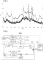
- Figure 1 shows a block diagram of the controlled apparatus 150.
- the controlled apparatus or system 150 consists of a combustion apparatus 50 and a control device 100 coupled with the combustion apparatus 50.
- combustion apparatus 50 is also referred to as combustor 50.
- a sensor 110 of the control device 100 is coupled with the combustor 50 to measure a parameter p related to a combustion state of the combustion apparatus 50 at different times t, for example pressure fluctuations.
- the sensor 110 is further coupled with a controller 120 of the device 100 so that the controller 120 can receive measured values p 1 (t) of the parameter p.
- the controller 120 may receive one measured values, typically several measured values p 1 per control cycle or a set of measured values p 1 per control cycle.
- the controller 120 determines time series S 0 (t) of the measured values p 1 (t) of the parameter p. This may include appending the measured value(s) p 1 (t) as or to an end of a storage structure such as an array, and an optional subsequent high-pass filtering.
- the controller 120 determines a primary control signal S(t) that is fed to an actuator 130 of the control device 100.
- the actuator 130 is connected with the controller 120 and coupled with the combustor 50.
- the actuator 130 converts the primary control signal S(t) into a secondary control signal p 2 (t) that is used to influence the combustion apparatus 50 in such a way that a chaotic combustion state of the combustion apparatus 50 is left and/or that the combustion apparatus 50 reaches a desired (non-chaotic) combustion state.
- a fuel-oxidant ratio of the combustion apparatus 50 may be modulated using the secondary control signal p 2 (t).
- the primary control signal S(t) is determined as function F of a first signal S 1 (t) and a second signal S 2 (t), typically as sum or weighted sum of the signals S 1 (t) and S 2 (t).
- the first signal S 1 (t) is determined by the controller 120 as follows.
- variable time delay ⁇ var may be initialized with a small value.
- the variable time delay ⁇ var may be initialized with a value close to a time-period which corresponds to a frequency of a dominant peak in the spectrum of the parameter.
- a time-shifted signal S ⁇ (t) is determined.
- variable time delay ⁇ var is changed and the processes for determining the difference signal may be repeated using the variable time delay ⁇ var .
- variable time delay ⁇ var and determining the difference signal S ⁇ (t, ⁇ var ) are repeated until the norm of the difference signal S ⁇ (t, ⁇ var ) reaches a smallest value.
- the finally determined difference signal S ⁇ is used as the first signal S 1 .
- the second signal S 2 (t) is determined by the controller 120 based on the frequency of a desired periodic state of the combustion apparatus 50.
- the second signal S 2 (t) is an open-loop control signal S OL (t).
- the second signal S 2 (t) is based on the time series S 0 (t) and a set time delay ⁇ set .
- the second signal S 2 (t) may be determined as delayed time series S 0 (t- ⁇ set ) or as a superposition S OL (t) + S 0 (t- ⁇ set ) or weighted superposition.
- the controller 120 is a two-stage controller that outputs a function F(S 1 (t), S 2 (t) ⁇ a k ⁇ ) as control signal S(t).
- the gains may be changed in time to achieve the desired combustion state. For example, a 2 may be set to 0 as long as the ⁇ var optimization is performed.
- a first of the two stages 121, 122 of the controller 120 is a feed-back control stage 121 and determines the first signal S 1 (t).
- a second of the two stages 121, 122 of the controller 120 determines the second signal S 2 (t).
- the second stage 122 may be (may operate as) a combined control stage (b 1 ⁇ 0, b 2 ⁇ 0).
- the controller 120 may also output a function G(S 0 (t), ⁇ a k , b i ⁇ , ⁇ set ) as control signal S(t) as illustrated in Fig. 2 .
- the set time delay ⁇ set may be modified till the combustion apparatus 50 reaches a desired combustion state with a desired frequency.
- control device 100 may have an observer unit 115 for determining a characteristic of a current state of the combustion apparatus 50 using the measured values p 1 (t) or the time series S 0 (t) (indicted by the dashed-dotted arrow).
- the observer unit 115 may change the function parameters ⁇ a k , b i ⁇ , ⁇ set explained above with respect to Fig. 2 .
- the observer unit 115 may increase the weight a 1 if the characteristic indicates that the current state is still chaotic.
- the observer unit 115 may decide to activate the controlling only (e.g. by assigning non-zero values to the weights a 1 and/or a 2 ) if desired, e.g. if a fluctuation characteristic is above a respective threshold.
- the observer unit 115 may be configured to deactivate the controlling or part thereof based on the characteristic(s).
- the observer unit 115 may also be an integral part of the controller 120.
- Figure 3 illustrates a flow diagram of a method 1000 that may be performed by the control device 100 explained above with respect to figures 1, 2 .
- a parameter (p) which is related to the combustion state such as a pressure in a combustion chamber or a (fluidically) connected upstream or downstream duct such as an exhaust pipe, for example a sound pressure, a temperature in the combustion chamber or the upstream or downstream duct, a temperature of a flame, and a radiation power of the flame is measured to obtain measured values (p 1 ) and therefrom a time series S 0 (t) of the parameter (p).
- control signal S(t) is used to influence the combustion apparatus 50.
- control signal S(t) may be fed to a suitable actuator such as an electromagnetically driven membrane or a valve of the combustion apparatus to modulate a fuel-oxidant ratio of the combustion apparatus.
- a suitable actuator such as an electromagnetically driven membrane or a valve of the combustion apparatus to modulate a fuel-oxidant ratio of the combustion apparatus.
- method 100 is typically performed in a cyclic/continuous manner.
- FIG 4 schematically illustrates an embodiment of a controlled combustion apparatus 450.
- the controlled combustion apparatus 450 is typically similar to the controlled apparatus 150 explained above with regard to figures 1, 2 , but described in more detail.
- the combustion apparatus 450 has two vertically orientated ducts 412, 414, typically steel ducts.
- the total length of the duct 412, 414 may be larger than 1 m and an inner diameter may be larger than about 10 cm.
- Reactants, fuel and air in the exemplary embodiment are injected at the bottom of the first (lower) duct 412 as indicated by the dashed arrows.
- the flow Prior to passing the upper duct 414, the flow may meet a perforated plate 413 employed as a holder to stabilize the flame in the upper duct 414.
- the plate 413 may e.g. have a hexagonal pattern of the holes.
- the flame remains stationary as the flame speed is equal to the speed of the unburnt flow at the flame location.
- perforated plates 413 as burners in a cross section of the reactant gas flow, heat is lost from the flame and the burning velocity decreases until it equals the unburnt mixture velocity. Therefore, a stable laminar flat flame confined in the upper duct 414 forming a combustion chamber is produced over a range of conditions.
- thermoacoustic coupling For example, a constructive feedback coupling between unsteady fluctuations in the flame and the acoustics of the combustion chamber (formed by upper duct 414) - plenum (formed by lower duct 412) assembly.
- a microphone 410 is attached to the lower duct 412 as sensor for measuring the pressure in the lower duct 412.
- the microphone may be attached to the upper duct 414.
- microphones may be used as sensors.
- measured pressure values p 1 (t) may be transferred from the microphone 410 to the two stages 421, 422 of the two-stage controller 421, 422.
- the controller stage 421 is implemented as feed-back control stage and configured to determine a first signal S 1 (t) as explained above with regard to Fig. 2 for the feed-back control stage 121.
- the controller stage 422 may have two subunits (sub-stages) 422a, 422b.
- the subunit 422a may determine the second signal S 2 (t) as open-loop control signal S OL (t), and subunit 422b may determine the second signal S 2 (t) a feedback signal S FB (t) as explained above with regard to Fig. 2 .
- the controller stage 422 may either provide the open-loop control signal S OL (t) (when the switch is in the switch setting shown in Fig. 4 ) or the feedback signal S FB (t) as second signal S 2 (t).
- each of the controller stages 421, 422 is connected with a corresponding compression driver 430 acting as actuators which are coupled with the lower duct 412.
- the actuators 430 are typically placed at identical axial distance from the flame in the duct 414.
- the compression drivers 430 typically include a respective electromagnetically driven membrane. Accordingly, the combustion process may be influenced sufficiently powerful and swift.
- the (voltage) signals S 1 (t), S 2 (t), and S(t), as described above may be used to generate a corresponding motion of the membrane.
- the motion of the membrane in turn generates pressure fluctuations that influence the thermoacoustic coupling between the acoustic field within the ducts 412, 414 and the flame.
- controller stages 421, 422 may be coupled with a common compression driver 430.
- Figure 5 shows frequency spectra a-c of pressure oscillations (psd) of the controlled combustor 450 shown in Figure 4 .
- Spectrum a corresponds to a chaotic combustion state of the combustor 450 with deactivated controller stages 421, 422 (uncontrolled combustion state).
- Spectrum a shows several pronounced broadband peaks, four of which are labelled as f 1 to f 4 .
- the combustor 450 is driven to and locked in the desired periodic state with main frequency f OL of 333 Hz.
- periodic combustion behavior can be locked to a desired frequency by changing the delay of the phase shift feedback (using sub stage 422b) or by changing the frequency of the open loop (using sub stage 422a). This may be particularly helpful for instance in combustors employing passive devices, which usually feature narrowband damping defined by their geometrical characteristics.
- the frequency of the instability can be adjusted to fall within the frequency band where the installed passive methods are effective.
- control device can be easily adjusted to follow (adapt to) any changes in the damper properties induced by changes in the operating conditions of the combustor.
- Figure 6 illustrates a flow diagram of a method 2000.
- the method 2000 is similar as the method 1000 explained above with regard to Fig. 3 , but explained in more detail.
- Method 2000 includes the blocks 2010, 2020 and 2030 which typically correspond to the respective blocks 1010, 1020 and 1030 of method 1000.
- the obtained time series S 0 (t) is initially analyzed in a block 2015 of method 2000.
- a value th representing amplitude fluctuations of the time series S 0 (t) (or the measured parameter values p 1 (t)) may be analyzed in a sub block 2015a of block 2015.
- control block 2020 may be activated. Otherwise, method 2000 may return from sub block 2015c of block 2015 to block 2010.
- sub block 2015c it may be decided in sub block 2015c to change one or more of the function parameters ⁇ a k , b i ⁇ , ⁇ set , f OL explained above, when the value th is above the threshold th1. Accordingly, current values of the function parameters ⁇ a k , b i ⁇ , ⁇ set , f OL may be updated in sub blocks 2016 and 2017 of block 2020, respectively.
- the second signal S 2 (t) may be combined with a first signal S 1 (t) determined in sub block 2021 of block 2020 as difference signal having a lowest (minimum) norm.
- the resulting primary control signal S(t) may be converted in a sub block 2031 of block 2030 into a secondary control signal p 2 (t) that is used in sub block 2032 of block 2030 to influence the combustion apparatus and the combustion state of the combustion apparatus, respectively .
- method 2000 may return to block 2010.
Description
- Embodiments of the present invention relate to methods and control devices for physical and chemical apparatuses in which undesired oscillations may emerge spontaneously due to a feedback coupling, in particular to methods and control devices for a combustion apparatus.
- Feedback coupling is inherent to many practical systems, and leads to oscillatory states (periodic states such as limit cycles and aperiodic states such as chaos) that may adversely affect the stability and safety of the systems such as an apparatus or even a whole plant. For example, a so-called thermoacoustic coupling may occur in apparatuses (systems) such as gas turbine engines, furnaces, boilers, rocket engines, and afterburners that are driven by confined combustion. Thermoacoustic coupling may lead to a self-excited instability, (also known as combustion instability, rumble, and reheat buzz), which appears spontaneously in the form of large amplitude pressure and heat release rate oscillations. The instability may be hazardous for the apparatus. Therefore, it is often desirable to suppress the thermoacoustic instabilities. Previously used control attempts (implicitly) assumed that the thermoacoustic instabilities correspond to limit cycle oscillations, possibly with harmonics. Therefore, the fact that the thermoacoustic system can undergo bifurcations to more complex nonlinear states, such as chaos is not taken into account. In fact, it is even possible that at onset of the instability when the system has just crossed the stability boundary, thermoacoustic oscillations correspond to a chaotic state. Previous methods will fail outright in such a scenario.
- Accordingly, there is a need to improve control/suppression of instabilities.
- The document
WO 85/03761 A1 - According to an embodiment of a method for controlling a combustion apparatus having a combustion state in which a parameter related to the combustion state reflects a chaotic behavior, the method includes measuring the parameter and determining a time series of the parameter. A variable time delay is changed, the time series is shifted by the variable time delay for determining a time-shifted signal, and a difference between the time-shifted signal and the time series is formed for determining a time dependent first signal until a norm of the difference between the time-shifted signal and the time series is lowest. A time dependent second signal different to the first signal is determined. Determining the time dependent second signal includes at least one of using a frequency of a desired periodic combustion state of the combustion apparatus, and shifting the time series by a set time delay. The first signal and the second signal are combined for determining a control signal. The control signal is used to influence the combustion apparatus.
- In the following, the difference between the time-shifted signal and the time series is also referred to as (time dependent) difference signal.
- In the following, the combustion state in which the parameter related to the combustion state reflects a chaotic behavior, typically a chaotic thermoacoustic instability, is also referred to as chaotic combustion state and chaotic state of combustion, respectively.
- The term "chaotic state" as used in this specification intends to describe a state of a system or apparatus exhibiting an aperiodic long-term behaviour with sensitive dependence on initial conditions. The term "aperiodic long-term behaviour" intends to describe that in the asymptotic dynamics the system or apparatus does not correspond to a fixed-point, a periodic orbit or a quasi-periodic behaviour. The system or apparatus may be (describable as) a non-linear deterministic system or apparatus, i.e. a system or apparatus in which the chaotic behaviour is not due to noisy or random forces, but rather due to the nonlinearity present in the system or apparatus, in particular a nonlinearity in the feedback coupling mechanism associated with thermoacoustic instability in the system or apparatus. The term "sensitive dependence on initial conditions" intends to describe that nearby initial conditions separate exponentially fast while the system or apparatus evolves in time.
- The method allows transferring the combustion apparatus from the chaotic combustion state into a periodic combustion state, and subsequently into a periodic state with a dominant frequency (of the parameter) shifted to the frequency of the desired oscillating state and/or a periodic state with reduced amplitude of oscillations compared to the initial state. Accordingly, hazardous instabilities of the combustion apparatus such as high mechanical loading can reliably be dampened or even suppressed. Further, other undesired effects that may occur in the chaotic state such as deterioration of exhaust values and exceeding of desired exhaust values, respectively, e.g. increased nitrogen oxide(s) (NOx), may be avoided.
- The first signal is effective to drive the combustion apparatus from a chaotic combustion state into a periodic combustion state.
- Using a desired main frequency of the desired periodic combustion state for determining the second signal and, thus, the control signal of the combustion apparatus, allows driving the combustion state towards, more typically into the desired combustion state. Further, a damping of the amplitude of the oscillation of the parameter may be achieved.
- Shifting the time series by a set time delay (τset which is different to the variable time delay τvar used to determine the time dependent first signal and the difference signal, respectively) to determine the second signal and, thus, the control signal of the combustion apparatus, also allows changing the dominant frequency of the combustion state as well as damping the amplitude of the oscillation of the parameter. Note that the set time delay (τset) determines the shift in the dominant frequency of the periodic combustion state.
- Whether an open-loop control based on the desired main frequency or a feed-back control using a set time delay (τset) is more efficient to drive the apparatus into the desired periodic combustion state may depend on the details of the apparatus.
- Both the variable time delay (τart) for the first signal S1 and the set time delay (τset) for the second signal S2 will typically be of the order of the time-period of the acoustic resonance frequency of the apparatus.
- The set time delay (τset) may be determined based on mechanical, geometrical, chemical and/or thermodynamic properties of the combustion apparatus. For example, the set time delay may be determined based on the acoustic resonance frequency of the combustion apparatus.
- The parameter may be any variable or observable that participates in the chaotic behaviour of the thermoacoustic oscillations.
- The term "thermoacoustic oscillations" intends to describe fluctuations and/or oscillations in a medium such as a gas which are due to a feedback interaction between an acoustic field in the medium, and temporal fluctuations in the heat release rate from combustion (or from a flame). The term "thermoacoustic oscillations" shall embrace oscillations in a flame (and associated quantities such as the unsteady heat release rate from the flame), and in an acoustic field within an apparatus at least partly enclosing the flame, typically within a combustion chamber of the apparatus, that emerge spontaneously due to a constructive feedback interaction between the flame and the acoustic field.
- The parameter may be a pressure in the apparatus, a temperature in the apparatus, a density in the apparatus, a radiation power of the combustion (typically a chemiluminescence from the flame) or a parameter related to one or more of the pressure, the temperature, the density and the radiation power.
- Typically, the parameter is the pressure. The pressure in the apparatus can reliably be measured with high temporal resolution.
- The measured values of the parameter are typically high-pass filtered. Accordingly, a (long-term) drift of the parameter is eliminated.
- The norm of the difference signal may be determined as an integral or a sum of (all) absolute amplitude values of the difference signal, e.g. as sum absolute pressure values. Alternatively, a root mean square value of the amplitude values of the difference signal may be determined as norm of the difference signal.
- To determine the first signal, the variable time delay is typically varied starting from a value close the inverse of the dominant frequency in the oscillations until the norm of the difference signal reaches a minimum value, typically a global minimum value.
- Accordingly, the amplitude of the first signal is small, typically close to zero if the apparatus is in a periodic state. Thus, the proposed controlling does not require analyzing the state of the apparatus and/or switching on and off the first signal.
- In one embodiment, determining the time dependent first signal includes determining a difference between a first subset of the time series and a second subset of the time series, wherein the variable time delay between the first second subset and the second subset is determined so that so that a norm of the difference signal determined as difference between the first subset and the second subset is lowest.
- Combining the first signal and the second signal is typically achieved by adding the first signal and the second signal or by forming a weighted sum of the first signal and the second signal.
- However, other functions F of the first signal and the second signal may also be used as control signal.
- Using the control signal may include feeding the input signal to an actuator coupled with the combustion apparatus.
- Using the control signal may also include converting the control signal to an input signal for the actuator and feeding the input signal to the actuator. For example, the input signal may be a time dependent voltage.
- For reasons of safety (for the actuator employed), the control signal or the input signal may be saturated prior to feeding to the actuator.
- Converting and/or saturating the control signal may also already be achieved during combining the first signal and the second signal using an appropriate function (F).
- The actuator is typically configured to convert the input signal, which is in the following also referred to as primary control signal into a secondary control signal suitable to influence the combustion apparatus.
- Typically, the primary control signal and the secondary control signal, respectively, may be used to modulate a fuel-oxidant ratio, e.g. a fuel-air ratio, of fuel and oxidant used in the combustion apparatus for combustion.
- This may be achieved by modulating a flow rate of the fuel and/or a flow rate of the oxidant.
- Modulating the fuel-oxidant ratio may be achieved with little additional expense and has been found to be efficient for transferring the combustion apparatus from the chaotic combustion state into a non-chaotic combustion state.
- Alternatively or in addition, the control signal or the saturated control signal may be converted into an acoustic signal, and the acoustic signal may be applied to the combustion apparatus.
- Typically, the method is performed in a cyclic manner and/or a continuously. Furthermore, the time series may be analyzed to determine a characteristic of a current combustion state, to change an input parameter of the function (F), e.g. increase a gain or weight of first signal if the current combustion state is still chaotic, and/or to change the set time delay.
- The characteristic may be a measure of non-periodicity, a distance from a bifurcation or the like.
- The characteristic may also be a fluctuation characteristic, in particular a measure for the amplitude oscillations such as a root-mean-square value (rms-value) of the measured values of the parameter or a measure of statistical dispersion of the measured values of the parameter such as the standard deviation. The fluctuation characteristic may be used to decide if the controlling is to be switched on.
- According to an embodiment of a control device, the control device includes a sensor for measuring a parameter related to a combustion state of a combustion apparatus, a controller coupled with the sensor, and an actuator coupled with the controller. The controller is configured to receive measured values of the parameter from the sensor and to determine a time series from the measured values of the parameter, to change a variable time delay, to shift the time series by the variable time delay for determining a time-shifted signal, and form a difference between the time-shifted signal and the time series for determining a time dependent first signal, until a norm of the difference between the time-shifted signal and the time series is lowest, to determine a time dependent second signal different to the first signal, wherein the second signal is determined based on a frequency of a desired oscillating state of the combustion apparatus and/or wherein determining the second signal comprises shifting the time series by a set time delay, and to outputting a function (F) of the first signal and the second signal as a primary control signal. The actuator is configured to convert the primary control signal into a secondary control signal suitable to influence the combustion apparatus.
- The control device is configured to vary the variable time delay, determine (a corresponding time-shifted signal and) a corresponding difference signal until the norm of the difference signal is lowest and reaches a minimum value, respectively, to determine the time dependent first signal.
- In the following the control device is also referred to as controller.
- Typically, the control device is configured to perform any of the methods described herein.
- The controller may include an observer unit configured to determine a characteristic of a current state of the combustion apparatus using the time series of the parameter. The observer unit may further be configured to change an input parameter of the function (F) and/or to change the set time delay.
- The sensor is typically a pressure sensor, a temperature sensor or a light sensor. The sensor may provide the measured values of the parameter as respective voltage values.
- The actuator may be an acoustic actuator, an electromagnetically driven membrane, a valve, for example a fast-response valve, or a pump.
- According to an embodiment, a controlled system includes a chamber, typically combustion chamber, and the control device coupled with the chamber.
- Typically, the controlled system forms a jet engine, a gas turbine engine, a furnace, a boiler, rocket engine, or an afterburner.
- The components in the figures are not necessarily to scale, instead emphasis being placed upon illustrating the principles of the invention. Moreover, in the figures, like reference numerals designate corresponding parts. In the drawings:
-
Figure 1 schematically illustrates a controlled apparatus including a control device according to an embodiment; -
Figure 2 illustrates the operation of the control device according to an embodiment; -
Figure 3 illustrates a flow diagram of a method according to an embodiment; -
Figure 4 schematically illustrates a controlled apparatus including a control device according to an embodiment; -
Figure 5 shows spectra referring to states of the controlled apparatus illustrated inFigure 4 ; and -
Figure 6 illustrates a flow diagram of a method according to an embodiment; - In the following Detailed Description, reference is made to the accompanying drawings, which form a part hereof, and in which is shown by way of illustration specific embodiments in which the invention may be practiced. In this regard, directional terminology, such as "top," "bottom," "front," "back," "leading," "trailing," etc., is used with reference to the orientation of the Figure(s) being described. Because components of embodiments can be positioned in a number of different orientations, the directional terminology is used for purposes of illustration and is in no way limiting. It is to be understood that other embodiments may be utilized and structural or logical changes may be made without departing from the scope of the present invention. The following detailed description, therefore, is not to be taken in a limiting sense, and the scope of the present invention is defined by the appended claims.
- Reference will now be made in detail to various embodiments, one or more examples of which are illustrated in the figures. Each example is provided by way of explanation, and is not meant as a limitation of the invention. For example, features illustrated or described as part of one embodiment can be used on or in conjunction with other embodiments to yield yet a further embodiment. The examples are described using specific language which should not be construed as limiting the scope of the appending claims. The drawings are not scaled and are for illustrative purposes only. For clarity, the same elements or manufacturing steps have been designated by the same references in the different drawings if not stated otherwise.
- With reference to
Figure 1 , a first embodiment of a controlledapparatus 150 is explained.Figure 1 shows a block diagram of the controlledapparatus 150. - In the exemplary embodiment, the controlled apparatus or
system 150 consists of acombustion apparatus 50 and acontrol device 100 coupled with thecombustion apparatus 50. - In the following the
combustion apparatus 50 is also referred to ascombustor 50. - A
sensor 110 of thecontrol device 100 is coupled with thecombustor 50 to measure a parameter p related to a combustion state of thecombustion apparatus 50 at different times t, for example pressure fluctuations. - The
sensor 110 is further coupled with acontroller 120 of thedevice 100 so that thecontroller 120 can receive measured values p1(t) of the parameter p. - The
controller 120 may receive one measured values, typically several measured values p1 per control cycle or a set of measured values p1 per control cycle. - Further, the
controller 120 determines time series S0(t) of the measured values p1(t) of the parameter p. This may include appending the measured value(s) p1(t) as or to an end of a storage structure such as an array, and an optional subsequent high-pass filtering. - Based on the time series S0(t), the
controller 120 determines a primary control signal S(t) that is fed to anactuator 130 of thecontrol device 100. - The
actuator 130 is connected with thecontroller 120 and coupled with thecombustor 50. - Accordingly, the
actuator 130 converts the primary control signal S(t) into a secondary control signal p2(t) that is used to influence thecombustion apparatus 50 in such a way that a chaotic combustion state of thecombustion apparatus 50 is left and/or that thecombustion apparatus 50 reaches a desired (non-chaotic) combustion state. - For example, a fuel-oxidant ratio of the
combustion apparatus 50 may be modulated using the secondary control signal p2(t). - As illustrated in
Figure 2 , the primary control signal S(t) is determined as function F of a first signal S1(t) and a second signal S 2(t), typically as sum or weighted sum of the signals S1(t) and S2(t). - The first signal S1(t) is determined by the
controller 120 as follows. - A variable time delay τvar may be initialized with a small value. Alternatively, the variable time delay τvar may be initialized with a value close to a time-period which corresponds to a frequency of a dominant peak in the spectrum of the parameter.
- Thereafter, a time-shifted signal Sτ(t) is determined. The time-shifted signal Sτ(t) is determined by time-shifting the time series S0(t) by the variable time delay τvar:

- Thereafter, a difference signal SΔ (t, τvar) = Sτ(t) - S0(t) = S0(t-τvar) - S0(t) is determined.
- Thereafter, a norm |SΔ (t, τvar)| of the difference signal SΔ (t, τvar) is determined.
- Thereafter, the variable time delay τvar is changed and the processes for determining the difference signal may be repeated using the variable time delay τvar.
- Changing the variable time delay τvar and determining the difference signal SΔ (t, τvar) are repeated until the norm of the difference signal SΔ (t, τvar) reaches a smallest value. The finally determined difference signal SΔ is used as the first signal S1.
- The second signal S2(t) is determined by the
controller 120 based on the frequency of a desired periodic state of thecombustion apparatus 50. In this embodiment, the second signal S2(t) is an open-loop control signal SOL(t). - Alternatively, or in addition, the second signal S2(t) is based on the time series S0(t) and a set time delay τset.
- For example, the second signal S2(t) may be determined as delayed time series S0(t-τset) or as a superposition SOL(t) + S0(t-τset) or weighted superposition.
- According to an embodiment, the
controller 120 is a two-stage controller that outputs a function F(S1(t), S2(t) {ak}) as control signal S(t). - Typically, F is a linear function: F (S1(t), S2(t) {ak}) = a1 S1(t) + a2 S2(t) with weights (gains) a1, a2 ({ak}). The gains may be changed in time to achieve the desired combustion state. For example, a2 may be set to 0 as long as the τvar optimization is performed.
- A first of the two
stages controller 120 is a feed-back control stage 121 and determines the first signal S1(t). - A second of the two
stages controller 120 determines the second signal S2(t). - For example, the
second stage 122 may determine the second signal S2(t) as a weighted sum of an open-loop control signal SOL(t) and a feedback signal SFB(t): S2(t) = b1 SOL(t) + b2 SFB(t), with weights (gains) b1, b2 ({bi}). - Thus, the
second stage 122 may be (may operate as) a feed-back control stage (b1=0) or an open-loop control stage (b2=0). - However, the
second stage 122 may be (may operate as) a combined control stage (b1 ≠ 0, b2 ≠ 0). - The open-loop control signal SOL(t) may be determined as a time periodic function H having a period which is inversely related to a (main) frequency (fOL) of a desired periodic combustion state: SOL(t)=H(t, fOL), such as a sinus function sin(2π∗fOL ∗t).
- The feedback signal SFB(t) is determined as time series S0(t) shifted by the set time delay τset: SFB(t) = S0(t - τset).
- In other words, the
controller 120 may also output a function G(S0(t), {ak, bi}, τset) as control signal S(t) as illustrated inFig. 2 . - The set time delay τset may be modified till the
combustion apparatus 50 reaches a desired combustion state with a desired frequency. - As further illustrated in
Fig. 1 , thecontrol device 100 may have anobserver unit 115 for determining a characteristic of a current state of thecombustion apparatus 50 using the measured values p1(t) or the time series S0(t) (indicted by the dashed-dotted arrow). - Depending on the characteristic, the
observer unit 115 may change the function parameters {ak, bi}, τset explained above with respect toFig. 2 . - For example, the
observer unit 115 may increase the weight a1 if the characteristic indicates that the current state is still chaotic. - Further, the
observer unit 115 may decide to activate the controlling only (e.g. by assigning non-zero values to the weights a1 and/or a2) if desired, e.g. if a fluctuation characteristic is above a respective threshold. - Likewise, the
observer unit 115 may be configured to deactivate the controlling or part thereof based on the characteristic(s). - The
observer unit 115 may also be an integral part of thecontroller 120. -
Figure 3 illustrates a flow diagram of amethod 1000 that may be performed by thecontrol device 100 explained above with respect tofigures 1, 2 . - In a
block 1010, a parameter (p) which is related to the combustion state such as a pressure in a combustion chamber or a (fluidically) connected upstream or downstream duct such as an exhaust pipe, for example a sound pressure, a temperature in the combustion chamber or the upstream or downstream duct, a temperature of a flame, and a radiation power of the flame is measured to obtain measured values (p1) and therefrom a time series S0(t) of the parameter (p). - In a
subsequent block 1020, a control signal S(t) may be determined on the basis of the time series S0(t). This is typically achieved as explained above with regard toFig. 2 for thecontroller 120 by combining the first signal S1(t) and the second signal S2(t), more typically as a function S(t) = G(S0(t), {ak, bi}, τset). - In a
subsequent block 1030, the control signal S(t) is used to influence thecombustion apparatus 50. - For example, the control signal S(t) may be fed to a suitable actuator such as an electromagnetically driven membrane or a valve of the combustion apparatus to modulate a fuel-oxidant ratio of the combustion apparatus.
- As illustrated by the dashed arrow in
Fig. 3 ,method 100 is typically performed in a cyclic/continuous manner. -
Figure 4 schematically illustrates an embodiment of a controlledcombustion apparatus 450. The controlledcombustion apparatus 450 is typically similar to the controlledapparatus 150 explained above with regard tofigures 1, 2 , but described in more detail. - In the exemplary embodiment, the
combustion apparatus 450 has two vertically orientatedducts duct - Reactants, fuel and air in the exemplary embodiment, are injected at the bottom of the first (lower)
duct 412 as indicated by the dashed arrows. Prior to passing theupper duct 414, the flow may meet aperforated plate 413 employed as a holder to stabilize the flame in theupper duct 414. Theplate 413 may e.g. have a hexagonal pattern of the holes. - Considering a one-dimensional configuration in longitudinal direction, the flame remains stationary as the flame speed is equal to the speed of the unburnt flow at the flame location. By using
perforated plates 413 as burners in a cross section of the reactant gas flow, heat is lost from the flame and the burning velocity decreases until it equals the unburnt mixture velocity. Therefore, a stable laminar flat flame confined in theupper duct 414 forming a combustion chamber is produced over a range of conditions. - However, hazardous self-excited instabilities may occur due to thermoacoustic coupling. For example, a constructive feedback coupling between unsteady fluctuations in the flame and the acoustics of the combustion chamber (formed by upper duct 414) - plenum (formed by lower duct 412) assembly.
- A
microphone 410 is attached to thelower duct 412 as sensor for measuring the pressure in thelower duct 412. - Alternatively, the microphone may be attached to the
upper duct 414. - Furthermore, several microphones may be used as sensors.
- In the exemplary embodiment, measured pressure values p1(t) may be transferred from the
microphone 410 to the twostages stage controller - The
controller stage 421 is implemented as feed-back control stage and configured to determine a first signal S1(t) as explained above with regard toFig. 2 for the feed-back control stage 121. - The
controller stage 422 may have two subunits (sub-stages) 422a, 422b. Thesubunit 422a may determine the second signal S2(t) as open-loop control signal SOL(t), andsubunit 422b may determine the second signal S2(t) a feedback signal SFB(t) as explained above with regard toFig. 2 . - Depending on the switch setting of the illustrated switch of the
controller stage 422, thecontroller stage 422 may either provide the open-loop control signal SOL(t) (when the switch is in the switch setting shown inFig. 4 ) or the feedback signal SFB(t) as second signal S2(t). - In the exemplary embodiment, each of the controller stages 421, 422 is connected with a corresponding
compression driver 430 acting as actuators which are coupled with thelower duct 412. Theactuators 430 are typically placed at identical axial distance from the flame in theduct 414. - The
compression drivers 430 typically include a respective electromagnetically driven membrane. Accordingly, the combustion process may be influenced sufficiently powerful and swift. The (voltage) signals S1(t), S2(t), and S(t), as described above may be used to generate a corresponding motion of the membrane. The motion of the membrane in turn generates pressure fluctuations that influence the thermoacoustic coupling between the acoustic field within theducts - Alternatively, the controller stages 421, 422 may be coupled with a
common compression driver 430. -
Figure 5 shows frequency spectra a-c of pressure oscillations (psd) of the controlledcombustor 450 shown inFigure 4 . Spectrum a corresponds to a chaotic combustion state of thecombustor 450 with deactivated controller stages 421, 422 (uncontrolled combustion state). Spectrum a shows several pronounced broadband peaks, four of which are labelled as f1 to f4. - After switching-on the controller stages 421, the chaotic combustion state is left as indicated by the resulting spectrum b.
- After further switching-on the controller stages 422 in the switch setting shown in
Fig. 4 and using second signal S2(t) which is periodic with a desired frequency fOL, thecombustor 450 is driven to and locked in the desired periodic state with main frequency fOL of 333 Hz. - It can be shown experimentally, that periodic combustion behavior can be locked to a desired frequency by changing the delay of the phase shift feedback (using
sub stage 422b) or by changing the frequency of the open loop (usingsub stage 422a). This may be particularly helpful for instance in combustors employing passive devices, which usually feature narrowband damping defined by their geometrical characteristics. - With the control devices described herein, the frequency of the instability can be adjusted to fall within the frequency band where the installed passive methods are effective.
- Furthermore, the control device can be easily adjusted to follow (adapt to) any changes in the damper properties induced by changes in the operating conditions of the combustor.
-
Figure 6 illustrates a flow diagram of amethod 2000. Themethod 2000 is similar as themethod 1000 explained above with regard toFig. 3 , but explained in more detail. -
Method 2000 includes theblocks respective blocks method 1000. - Furthermore, after measuring values p1(t) of the parameter in
block 2010, the obtained time series S0(t) is initially analyzed in ablock 2015 ofmethod 2000. - For example, a value th representing amplitude fluctuations of the time series S0(t) (or the measured parameter values p1(t)) may be analyzed in a
sub block 2015a ofblock 2015. - If the value th is above a predetermined threshold th1,
control block 2020 may be activated. Otherwise,method 2000 may return fromsub block 2015c ofblock 2015 to block 2010. - Furthermore, based on the analysis in
block 2015a, it may be decided insub block 2015c to change one or more of the function parameters {ak, bi}, τset, fOL explained above, when the value th is above the threshold th1. Accordingly, current values of the function parameters {ak, bi}, τset, fOL may be updated insub blocks block 2020, respectively. - Furthermore, it may be decided based on the analysis in
block 2015a to change in asub block 2018 of block 2020 a switch setting and, thus, how the open-loop control signal SOL(t) determined in asub block 2022a ofblock 2020 and the feedback signal SFB(t) determined in asub block 2022b ofblock 2020 are combined for forming the second signal S2(t). - Similar as explained above with regard to
Fig. 2 , the second signal S2(t) may be combined with a first signal S1(t) determined insub block 2021 ofblock 2020 as difference signal having a lowest (minimum) norm. - The resulting primary control signal S(t) may be converted in a
sub block 2031 ofblock 2030 into a secondary control signal p2(t) that is used insub block 2032 ofblock 2030 to influence the combustion apparatus and the combustion state of the combustion apparatus, respectively . - Thereafter,
method 2000 may return to block 2010. - Although various exemplary embodiments of the invention have been disclosed, it will be apparent to those skilled in the art that various changes and modifications can be made which will achieve some of the advantages of the invention without departing from the scope of the invention.
- Spatially relative terms such as "under", "below", "lower", "over", "upper" and the like are used for ease of description to explain the positioning of one element relative to a second element. These terms are intended to encompass different orientations of the device in addition to different orientations than those depicted in the figures. Further, terms such as "first", "second", and the like, are also used to describe various elements, regions, sections, etc. and are also not intended to be limiting. Like terms refer to like elements throughout the description.
- As used herein, the terms "having", "containing", "including", "comprising" and the like are open ended terms that indicate the presence of stated elements or features, but do not preclude additional elements or features. The articles "a", "an" and "the" are intended to include the plural as well as the singular, unless the context clearly indicates otherwise.
- With the above range of variations and applications in mind, it should be understood that the present invention is not limited by the foregoing description, nor is it limited by the accompanying drawings. Instead, the present invention is limited only by the following claims.
Claims (15)
- A method (1000, 2000) for controlling a combustion apparatus (50) comprising a combustion state in which a parameter (p) related to the combustion state reflects a chaotic behavior, the method comprising:- measuring the parameter (p) and determining a time series (So, p1) of the parameter (p);- changing a variable time delay (τvar), shifting the time series (S0) by the variable time delay (τvar) for determining a time-shifted signal (Sτ), and forming a difference (Sτ - So) between the time-shifted signal (Sτ) and the time series (S0) for determining a time dependent first signal (S1) until a norm of the difference (Sτ - So) between the time-shifted signal (Sτ) and the time series (S0) is lowest;- determining a time dependent second signal (S2) different to the first signal (S1), wherein determining the time dependent second signal (S2) comprises at least one of using a frequency (fOL) of a desired periodic combustion state of the combustion apparatus (50), and shifting the time series (S0) by a set time delay (τset);- combining the first signal (S1) and the second signal (S2) for determining a control signal (S, p2); and- using the control signal (S, p2) to influence the combustion apparatus (50).
- The method of claim 1, wherein combining the first signal (S1) and the second signal (S2) comprises at least one of determining a function (F) of the first signal (S1) and the second signal (S2), determining a sum of the first signal (S1) and the second signal (S2), and determining a weighted sum of the first signal (S1) and the second signal (S2).
- The method of any preceding claim, wherein the norm corresponds to a sum of absolute amplitude values of the difference (ST - So) between the time-shifted signal (Sτ) and the time series (S0), and/or wherein the norm corresponds to a root mean square value of the amplitude values of the difference (ST - So) between the time-shifted signal (Sτ) and the time series (S0), and/or wherein the variable time delay (τvar) is changed starting from a value close to an inverse of a dominant frequency of the desired periodic combustion state until the norm of the difference (Sτ - So) between the time-shifted signal (Sτ) and the time series (S0) reaches a minimum value.
- The method of any preceding claim, wherein the parameter is a pressure in the apparatus, a temperature in the apparatus, a density in the apparatus, a radiation power of the combustion or a parameter related to at least one of the pressure, the temperature, the density and the radiation power.
- The method of any preceding claim, further comprising analyzing the time series (S0) to determine a characteristic of a current state of the combustion, changing an input parameter ({a}) of the function (F) and/or changing the set time delay (τset).
- The method of any preceding claim, wherein determining the time series (S0) comprises high-pass filtering the measured parameter (p1), and/or wherein determining the time dependent first signal (S1) comprises varying the variable time delay (τvar).
- The method of any preceding claim, wherein using the control signal (S, p2) comprises at least one of:- saturating the control signal (S) to form a saturated control signal;- feeding the control signal (S) or the saturated control signal to an actuator (130, 430) coupled with the combustion apparatus (50);- modulating a fuel-oxidant ratio of the combustion apparatus (50);- modulating a flow rate of the combustion apparatus (50); and at least the first step of the following two steps:- converting the control signal (S) or the saturated control signal into an acoustic signal; and- applying the acoustic signal to the combustion apparatus (50).
- The method of any preceding claim, wherein the method is performed in a cyclic manner and/or a continuously.
- A control device (100), comprising:- a sensor (110, 410) for measuring a parameter (p) related to a combustion state of a combustion apparatus (50);- a controller (120, 421, 422) connected with the sensor (110, 410) and configured to:- receive measured values (p1) of the parameter (p) from the sensor (110) and to determine a time series (S0) of the measured values of the parameter (p);- change a variable time delay (τvar), shift the time series (S0) by the variable time delay (τvar) for determining a time-shifted signal (Sτ), and form a difference (ST - So) between the time-shifted signal (Sτ) and the time series (S0) for determining a time dependent first signal (S1) until a norm of the difference (ST - So) between the time-shifted signal (Sτ) and the time series (S0) is lowest;- determine a time dependent second signal (S2) different to the first signal (S1), wherein the second signal (S2) is determined based on a frequency (fOL) of a desired periodic state of the combustion apparatus (50) and/or wherein determining the second signal (S2) comprises shifting the time series (S0) by a set time delay (τset); and- outputting a function (F) of the first signal (S1) and the second signal (S2) as a primary control signal (S); and- an actuator (130, 430) connected with the controller (120) and configured to convert the primary control signal (S) into a secondary control signal (p2) suitable to influence the combustion apparatus (50).
- The device of claim 9, wherein the sensor (110, 410) is a pressure sensor, a temperature sensor or a light sensor.
- The device of claim 9 or 10, wherein the actuator (130, 430) is an acoustic actuator, an electromagnetically driven membrane, a valve or a pump.
- The device of any of the claims 9 to 11, wherein the control device (100, 421, 422) comprises an observer unit (115) configured to determine at least one of:- a characteristic of a current state of the combustion apparatus using the time series (S0) or the measured values (p1) of the parameter (p);- using the characteristic for changing an input parameter ({a}) of the function (F); and- using the characteristic for changing the set time delay (τset).
- The device of any of the claims 9 to 12, wherein the control device (100, 421, 422) is configured to perform the method of any of the claims 1 to 8.
- A controlled system (150, 450) comprising a chamber (412, 414) and the control device (100) any of the claims 9 to 13 coupled with the chamber (412, 414).
- The system of claim 14, wherein the chamber is a combustion chamber (412, 414), and/or wherein the controlled system is formed by or includes at least one of a jet engine, a rocket engine, a gas turbine engine, a furnace, a boiler, and an afterburner.
Priority Applications (4)
| Application Number | Priority Date | Filing Date | Title |
|---|---|---|---|
| EP17189064.3A EP3450848B1 (en) | 2017-09-01 | 2017-09-01 | Method for controlling a combustion apparatus and control device |
| US16/638,408 US11525417B2 (en) | 2017-09-01 | 2018-08-21 | Method for controlling a combustion apparatus and control device |
| PCT/EP2018/072484 WO2019042813A1 (en) | 2017-09-01 | 2018-08-21 | Method for controlling a combustion apparatus and control device |
| CN201880056685.8A CN111033125B (en) | 2017-09-01 | 2018-08-21 | Method and control device for controlling a combustion system |
Applications Claiming Priority (1)
| Application Number | Priority Date | Filing Date | Title |
|---|---|---|---|
| EP17189064.3A EP3450848B1 (en) | 2017-09-01 | 2017-09-01 | Method for controlling a combustion apparatus and control device |
Publications (2)
| Publication Number | Publication Date |
|---|---|
| EP3450848A1 EP3450848A1 (en) | 2019-03-06 |
| EP3450848B1 true EP3450848B1 (en) | 2021-01-06 |
Family
ID=59772472
Family Applications (1)
| Application Number | Title | Priority Date | Filing Date |
|---|---|---|---|
| EP17189064.3A Active EP3450848B1 (en) | 2017-09-01 | 2017-09-01 | Method for controlling a combustion apparatus and control device |
Country Status (4)
| Country | Link |
|---|---|
| US (1) | US11525417B2 (en) |
| EP (1) | EP3450848B1 (en) |
| CN (1) | CN111033125B (en) |
| WO (1) | WO2019042813A1 (en) |
Families Citing this family (3)
| Publication number | Priority date | Publication date | Assignee | Title |
|---|---|---|---|---|
| EP3450848B1 (en) | 2017-09-01 | 2021-01-06 | Technische Universität Berlin | Method for controlling a combustion apparatus and control device |
| CN112326730A (en) * | 2020-10-21 | 2021-02-05 | 北京航空航天大学 | Experimental method and device for measuring heat release rate pulsation by adopting multiple microphones |
| CN113654024A (en) * | 2021-08-24 | 2021-11-16 | 北京天衡智联科技有限公司 | Steam boiler pipeline pressure coordinated control system |
Family Cites Families (13)
| Publication number | Priority date | Publication date | Assignee | Title |
|---|---|---|---|---|
| US4473906A (en) | 1980-12-05 | 1984-09-25 | Lord Corporation | Active acoustic attenuator |
| EP0172198A1 (en) * | 1984-02-22 | 1986-02-26 | Vulcan Australia Limited | Gas heaters and control thereof |
| JPS61125521A (en) | 1984-11-21 | 1986-06-13 | Rinnai Corp | Control unit of burner |
| US7832211B2 (en) | 2002-12-02 | 2010-11-16 | Mitsubishi Heavy Industries, Ltd. | Gas turbine combustor and a gas turbine equipped therewith |
| DE10257244A1 (en) * | 2002-12-07 | 2004-07-15 | Alstom Technology Ltd | Method and device for influencing thermoacoustic vibrations in combustion systems |
| EP1704317B8 (en) | 2004-01-12 | 2008-05-07 | VDO Automotive AG | Control method and control device for an actuator |
| EP1762786A1 (en) * | 2005-09-13 | 2007-03-14 | Siemens Aktiengesellschaft | Process and apparatus to dampen thermo-accoustic vibrations, in particular within a gas turbine |
| DE102008004229A1 (en) * | 2008-01-14 | 2009-07-16 | GM Global Technology Operations, Inc., Detroit | System and method for controlling combustion phases in an internal combustion engine |
| IN2013CH05590A (en) * | 2013-12-04 | 2015-08-28 | Indian Inst Technology Madras | |
| KR101667104B1 (en) | 2014-07-17 | 2016-10-17 | 한국전력공사 | Method for controlling combustion instability |
| JP2018178745A (en) * | 2017-04-04 | 2018-11-15 | トヨタ自動車株式会社 | Controller of internal combustion engine |
| EP3450848B1 (en) | 2017-09-01 | 2021-01-06 | Technische Universität Berlin | Method for controlling a combustion apparatus and control device |
| CN112326730A (en) | 2020-10-21 | 2021-02-05 | 北京航空航天大学 | Experimental method and device for measuring heat release rate pulsation by adopting multiple microphones |
-
2017
- 2017-09-01 EP EP17189064.3A patent/EP3450848B1/en active Active
-
2018
- 2018-08-21 WO PCT/EP2018/072484 patent/WO2019042813A1/en active Application Filing
- 2018-08-21 US US16/638,408 patent/US11525417B2/en active Active
- 2018-08-21 CN CN201880056685.8A patent/CN111033125B/en active Active
Non-Patent Citations (1)
| Title |
|---|
| None * |
Also Published As
| Publication number | Publication date |
|---|---|
| EP3450848A1 (en) | 2019-03-06 |
| WO2019042813A1 (en) | 2019-03-07 |
| CN111033125B (en) | 2021-12-31 |
| US11525417B2 (en) | 2022-12-13 |
| CN111033125A (en) | 2020-04-17 |
| US20200200110A1 (en) | 2020-06-25 |
Similar Documents
| Publication | Publication Date | Title |
|---|---|---|
| US11525417B2 (en) | Method for controlling a combustion apparatus and control device | |
| US5428951A (en) | Method and apparatus for active control of combustion devices | |
| Annaswamy et al. | Active control of combustion instability: Theory and practice | |
| McManus et al. | A review of active control of combustion instabilities | |
| Zhao et al. | Minimizing transient energy growth of nonlinear thermoacoustic oscillations | |
| Morgans et al. | Model-based control of combustion instabilities | |
| Neumeier | Experimental demonstration of active control of combustion instabilities using real-time modes observation and secondary fuel injection | |
| Bošković et al. | Stabilization of a solid propellant rocket instability by state feedback | |
| Li et al. | Unity maximum transient energy growth of heat-driven acoustic oscillations | |
| Kulkarni et al. | Non-normality and its consequences in active control of thermoacoustic instabilities | |
| Evesque et al. | Self-tuning regulators for combustion oscillations | |
| CN111043623A (en) | Method for preventing combustion chamber from generating resonance based on closed-loop negative feedback regulation of electric field influencing flame root | |
| EP3182008A1 (en) | Helmholtz damper for a gas turbine and gas turbine with such helmholtz damper | |
| US5361710A (en) | Method and apparatus for the active control of a compact waste incinerator | |
| Manoj et al. | Rijke tube: A nonlinear oscillator | |
| Bellows et al. | Nonlinear interactions between forced and self-excited acoustic oscillations in premixed combustor | |
| Kabiraj et al. | A review on noise-induced dynamics of thermoacoustic systems | |
| Schimek et al. | An experimental investigation of the nonlinear response of an atmospheric swirl-stabilized premixed flame | |
| Gutmark et al. | Closed-loop control in a flame and a dump combustor | |
| Hathout | Thermoacoustic instability | |
| Moeck et al. | Two-parameter extremum seeking for control of thermoacoustic instabilities and characterization of linear growth | |
| Deshmukh et al. | Development of closed-loop active control method for suppression of thermoacoustic instability using radial air micro-jets | |
| Auer et al. | Active instability control: feedback of combustion instabilities on the injection of gaseous fuel | |
| Zhang et al. | Feedback control of Rijke-type thermoacoustic oscillations transient growth | |
| Bellows et al. | Nonlinear response of a premixed combustor to forced acoustic oscillations |
Legal Events
| Date | Code | Title | Description |
|---|---|---|---|
| PUAI | Public reference made under article 153(3) epc to a published international application that has entered the european phase |
Free format text: ORIGINAL CODE: 0009012 |
|
| STAA | Information on the status of an ep patent application or granted ep patent |
Free format text: STATUS: THE APPLICATION HAS BEEN PUBLISHED |
|
| AK | Designated contracting states |
Kind code of ref document: A1 Designated state(s): AL AT BE BG CH CY CZ DE DK EE ES FI FR GB GR HR HU IE IS IT LI LT LU LV MC MK MT NL NO PL PT RO RS SE SI SK SM TR |
|
| AX | Request for extension of the european patent |
Extension state: BA ME |
|
| STAA | Information on the status of an ep patent application or granted ep patent |
Free format text: STATUS: REQUEST FOR EXAMINATION WAS MADE |
|
| 17P | Request for examination filed |
Effective date: 20190902 |
|
| RBV | Designated contracting states (corrected) |
Designated state(s): AL AT BE BG CH CY CZ DE DK EE ES FI FR GB GR HR HU IE IS IT LI LT LU LV MC MK MT NL NO PL PT RO RS SE SI SK SM TR |
|
| STAA | Information on the status of an ep patent application or granted ep patent |
Free format text: STATUS: EXAMINATION IS IN PROGRESS |
|
| 17Q | First examination report despatched |
Effective date: 20200117 |
|
| GRAP | Despatch of communication of intention to grant a patent |
Free format text: ORIGINAL CODE: EPIDOSNIGR1 |
|
| STAA | Information on the status of an ep patent application or granted ep patent |
Free format text: STATUS: GRANT OF PATENT IS INTENDED |
|
| INTG | Intention to grant announced |
Effective date: 20200722 |
|
| GRAS | Grant fee paid |
Free format text: ORIGINAL CODE: EPIDOSNIGR3 |
|
| GRAA | (expected) grant |
Free format text: ORIGINAL CODE: 0009210 |
|
| STAA | Information on the status of an ep patent application or granted ep patent |
Free format text: STATUS: THE PATENT HAS BEEN GRANTED |
|
| RIN1 | Information on inventor provided before grant (corrected) |
Inventor name: SAURABH, ADITYA Inventor name: LIPIKA, KABIRAJ Inventor name: PASCHEREIT, CHRISTIAN OLIVER |
|
| AK | Designated contracting states |
Kind code of ref document: B1 Designated state(s): AL AT BE BG CH CY CZ DE DK EE ES FI FR GB GR HR HU IE IS IT LI LT LU LV MC MK MT NL NO PL PT RO RS SE SI SK SM TR |
|
| REG | Reference to a national code |
Ref country code: GB Ref legal event code: FG4D |
|
| REG | Reference to a national code |
Ref country code: AT Ref legal event code: REF Ref document number: 1352765 Country of ref document: AT Kind code of ref document: T Effective date: 20210115 Ref country code: CH Ref legal event code: EP |
|
| REG | Reference to a national code |
Ref country code: DE Ref legal event code: R096 Ref document number: 602017030807 Country of ref document: DE |
|
| REG | Reference to a national code |
Ref country code: IE Ref legal event code: FG4D |
|
| REG | Reference to a national code |
Ref country code: SE Ref legal event code: TRGR |
|
| REG | Reference to a national code |
Ref country code: NL Ref legal event code: MP Effective date: 20210106 |
|
| REG | Reference to a national code |
Ref country code: AT Ref legal event code: MK05 Ref document number: 1352765 Country of ref document: AT Kind code of ref document: T Effective date: 20210106 |
|
| REG | Reference to a national code |
Ref country code: NO Ref legal event code: T2 Effective date: 20210106 |
|
| REG | Reference to a national code |
Ref country code: LT Ref legal event code: MG9D |
|
| PG25 | Lapsed in a contracting state [announced via postgrant information from national office to epo] |
Ref country code: FI Free format text: LAPSE BECAUSE OF FAILURE TO SUBMIT A TRANSLATION OF THE DESCRIPTION OR TO PAY THE FEE WITHIN THE PRESCRIBED TIME-LIMIT Effective date: 20210106 Ref country code: HR Free format text: LAPSE BECAUSE OF FAILURE TO SUBMIT A TRANSLATION OF THE DESCRIPTION OR TO PAY THE FEE WITHIN THE PRESCRIBED TIME-LIMIT Effective date: 20210106 Ref country code: GR Free format text: LAPSE BECAUSE OF FAILURE TO SUBMIT A TRANSLATION OF THE DESCRIPTION OR TO PAY THE FEE WITHIN THE PRESCRIBED TIME-LIMIT Effective date: 20210407 Ref country code: PT Free format text: LAPSE BECAUSE OF FAILURE TO SUBMIT A TRANSLATION OF THE DESCRIPTION OR TO PAY THE FEE WITHIN THE PRESCRIBED TIME-LIMIT Effective date: 20210506 Ref country code: LT Free format text: LAPSE BECAUSE OF FAILURE TO SUBMIT A TRANSLATION OF THE DESCRIPTION OR TO PAY THE FEE WITHIN THE PRESCRIBED TIME-LIMIT Effective date: 20210106 Ref country code: BG Free format text: LAPSE BECAUSE OF FAILURE TO SUBMIT A TRANSLATION OF THE DESCRIPTION OR TO PAY THE FEE WITHIN THE PRESCRIBED TIME-LIMIT Effective date: 20210406 |
|
| PG25 | Lapsed in a contracting state [announced via postgrant information from national office to epo] |
Ref country code: AT Free format text: LAPSE BECAUSE OF FAILURE TO SUBMIT A TRANSLATION OF THE DESCRIPTION OR TO PAY THE FEE WITHIN THE PRESCRIBED TIME-LIMIT Effective date: 20210106 Ref country code: PL Free format text: LAPSE BECAUSE OF FAILURE TO SUBMIT A TRANSLATION OF THE DESCRIPTION OR TO PAY THE FEE WITHIN THE PRESCRIBED TIME-LIMIT Effective date: 20210106 Ref country code: LV Free format text: LAPSE BECAUSE OF FAILURE TO SUBMIT A TRANSLATION OF THE DESCRIPTION OR TO PAY THE FEE WITHIN THE PRESCRIBED TIME-LIMIT Effective date: 20210106 Ref country code: RS Free format text: LAPSE BECAUSE OF FAILURE TO SUBMIT A TRANSLATION OF THE DESCRIPTION OR TO PAY THE FEE WITHIN THE PRESCRIBED TIME-LIMIT Effective date: 20210106 |
|
| PG25 | Lapsed in a contracting state [announced via postgrant information from national office to epo] |
Ref country code: IS Free format text: LAPSE BECAUSE OF FAILURE TO SUBMIT A TRANSLATION OF THE DESCRIPTION OR TO PAY THE FEE WITHIN THE PRESCRIBED TIME-LIMIT Effective date: 20210506 |
|
| REG | Reference to a national code |
Ref country code: DE Ref legal event code: R097 Ref document number: 602017030807 Country of ref document: DE |
|
| PG25 | Lapsed in a contracting state [announced via postgrant information from national office to epo] |
Ref country code: EE Free format text: LAPSE BECAUSE OF FAILURE TO SUBMIT A TRANSLATION OF THE DESCRIPTION OR TO PAY THE FEE WITHIN THE PRESCRIBED TIME-LIMIT Effective date: 20210106 Ref country code: CZ Free format text: LAPSE BECAUSE OF FAILURE TO SUBMIT A TRANSLATION OF THE DESCRIPTION OR TO PAY THE FEE WITHIN THE PRESCRIBED TIME-LIMIT Effective date: 20210106 Ref country code: SM Free format text: LAPSE BECAUSE OF FAILURE TO SUBMIT A TRANSLATION OF THE DESCRIPTION OR TO PAY THE FEE WITHIN THE PRESCRIBED TIME-LIMIT Effective date: 20210106 |
|
| PLBE | No opposition filed within time limit |
Free format text: ORIGINAL CODE: 0009261 |
|
| STAA | Information on the status of an ep patent application or granted ep patent |
Free format text: STATUS: NO OPPOSITION FILED WITHIN TIME LIMIT |
|
| PG25 | Lapsed in a contracting state [announced via postgrant information from national office to epo] |
Ref country code: SK Free format text: LAPSE BECAUSE OF FAILURE TO SUBMIT A TRANSLATION OF THE DESCRIPTION OR TO PAY THE FEE WITHIN THE PRESCRIBED TIME-LIMIT Effective date: 20210106 Ref country code: RO Free format text: LAPSE BECAUSE OF FAILURE TO SUBMIT A TRANSLATION OF THE DESCRIPTION OR TO PAY THE FEE WITHIN THE PRESCRIBED TIME-LIMIT Effective date: 20210106 Ref country code: DK Free format text: LAPSE BECAUSE OF FAILURE TO SUBMIT A TRANSLATION OF THE DESCRIPTION OR TO PAY THE FEE WITHIN THE PRESCRIBED TIME-LIMIT Effective date: 20210106 |
|
| 26N | No opposition filed |
Effective date: 20211007 |
|
| PG25 | Lapsed in a contracting state [announced via postgrant information from national office to epo] |
Ref country code: AL Free format text: LAPSE BECAUSE OF FAILURE TO SUBMIT A TRANSLATION OF THE DESCRIPTION OR TO PAY THE FEE WITHIN THE PRESCRIBED TIME-LIMIT Effective date: 20210106 Ref country code: ES Free format text: LAPSE BECAUSE OF FAILURE TO SUBMIT A TRANSLATION OF THE DESCRIPTION OR TO PAY THE FEE WITHIN THE PRESCRIBED TIME-LIMIT Effective date: 20210106 |
|
| PG25 | Lapsed in a contracting state [announced via postgrant information from national office to epo] |
Ref country code: SI Free format text: LAPSE BECAUSE OF FAILURE TO SUBMIT A TRANSLATION OF THE DESCRIPTION OR TO PAY THE FEE WITHIN THE PRESCRIBED TIME-LIMIT Effective date: 20210106 |
|
| REG | Reference to a national code |
Ref country code: BE Ref legal event code: MM Effective date: 20210930 |
|
| PG25 | Lapsed in a contracting state [announced via postgrant information from national office to epo] |
Ref country code: IS Free format text: LAPSE BECAUSE OF FAILURE TO SUBMIT A TRANSLATION OF THE DESCRIPTION OR TO PAY THE FEE WITHIN THE PRESCRIBED TIME-LIMIT Effective date: 20210506 Ref country code: MC Free format text: LAPSE BECAUSE OF FAILURE TO SUBMIT A TRANSLATION OF THE DESCRIPTION OR TO PAY THE FEE WITHIN THE PRESCRIBED TIME-LIMIT Effective date: 20210106 |
|
| PG25 | Lapsed in a contracting state [announced via postgrant information from national office to epo] |
Ref country code: LU Free format text: LAPSE BECAUSE OF NON-PAYMENT OF DUE FEES Effective date: 20210901 Ref country code: IE Free format text: LAPSE BECAUSE OF NON-PAYMENT OF DUE FEES Effective date: 20210901 Ref country code: BE Free format text: LAPSE BECAUSE OF NON-PAYMENT OF DUE FEES Effective date: 20210930 |
|
| PG25 | Lapsed in a contracting state [announced via postgrant information from national office to epo] |
Ref country code: IT Free format text: LAPSE BECAUSE OF NON-PAYMENT OF DUE FEES Effective date: 20210901 |
|
| TPAB | Information related to observations by third parties deleted |
Free format text: ORIGINAL CODE: EPIDOSDTIPA |
|
| TPAC | Observations filed by third parties |
Free format text: ORIGINAL CODE: EPIDOSNTIPA |
|
| PG25 | Lapsed in a contracting state [announced via postgrant information from national office to epo] |
Ref country code: CY Free format text: LAPSE BECAUSE OF FAILURE TO SUBMIT A TRANSLATION OF THE DESCRIPTION OR TO PAY THE FEE WITHIN THE PRESCRIBED TIME-LIMIT Effective date: 20210106 Ref country code: NL Free format text: LAPSE BECAUSE OF NON-PAYMENT OF DUE FEES Effective date: 20210206 |
|
| PG25 | Lapsed in a contracting state [announced via postgrant information from national office to epo] |
Ref country code: HU Free format text: LAPSE BECAUSE OF FAILURE TO SUBMIT A TRANSLATION OF THE DESCRIPTION OR TO PAY THE FEE WITHIN THE PRESCRIBED TIME-LIMIT; INVALID AB INITIO Effective date: 20170901 |
|
| PGFP | Annual fee paid to national office [announced via postgrant information from national office to epo] |
Ref country code: NO Payment date: 20230919 Year of fee payment: 7 Ref country code: GB Payment date: 20230921 Year of fee payment: 7 |
|
| PGFP | Annual fee paid to national office [announced via postgrant information from national office to epo] |
Ref country code: SE Payment date: 20230921 Year of fee payment: 7 Ref country code: FR Payment date: 20230918 Year of fee payment: 7 Ref country code: DE Payment date: 20230919 Year of fee payment: 7 |
|
| PGFP | Annual fee paid to national office [announced via postgrant information from national office to epo] |
Ref country code: CH Payment date: 20231001 Year of fee payment: 7 |