EP3450788A1 - A disc brake - Google Patents
A disc brake Download PDFInfo
- Publication number
- EP3450788A1 EP3450788A1 EP17188746.6A EP17188746A EP3450788A1 EP 3450788 A1 EP3450788 A1 EP 3450788A1 EP 17188746 A EP17188746 A EP 17188746A EP 3450788 A1 EP3450788 A1 EP 3450788A1
- Authority
- EP
- European Patent Office
- Prior art keywords
- disc brake
- brake
- piston
- rotatable portion
- axis
- Prior art date
- Legal status (The legal status is an assumption and is not a legal conclusion. Google has not performed a legal analysis and makes no representation as to the accuracy of the status listed.)
- Granted
Links
- 230000033001 locomotion Effects 0.000 claims description 12
- 239000002783 friction material Substances 0.000 description 9
- 230000005540 biological transmission Effects 0.000 description 4
- 230000006835 compression Effects 0.000 description 4
- 238000007906 compression Methods 0.000 description 4
- 238000007789 sealing Methods 0.000 description 3
- 230000000694 effects Effects 0.000 description 2
- 239000000463 material Substances 0.000 description 2
- 230000001154 acute effect Effects 0.000 description 1
- 238000005266 casting Methods 0.000 description 1
- 238000000576 coating method Methods 0.000 description 1
- 238000009434 installation Methods 0.000 description 1
- 239000000314 lubricant Substances 0.000 description 1
- 238000005461 lubrication Methods 0.000 description 1
- 238000004806 packaging method and process Methods 0.000 description 1
- 239000004810 polytetrafluoroethylene Substances 0.000 description 1
- 229920001343 polytetrafluoroethylene Polymers 0.000 description 1
Images


Classifications
-
- F—MECHANICAL ENGINEERING; LIGHTING; HEATING; WEAPONS; BLASTING
- F16—ENGINEERING ELEMENTS AND UNITS; GENERAL MEASURES FOR PRODUCING AND MAINTAINING EFFECTIVE FUNCTIONING OF MACHINES OR INSTALLATIONS; THERMAL INSULATION IN GENERAL
- F16D—COUPLINGS FOR TRANSMITTING ROTATION; CLUTCHES; BRAKES
- F16D65/00—Parts or details
- F16D65/38—Slack adjusters
- F16D65/40—Slack adjusters mechanical
- F16D65/42—Slack adjusters mechanical non-automatic
-
- F—MECHANICAL ENGINEERING; LIGHTING; HEATING; WEAPONS; BLASTING
- F16—ENGINEERING ELEMENTS AND UNITS; GENERAL MEASURES FOR PRODUCING AND MAINTAINING EFFECTIVE FUNCTIONING OF MACHINES OR INSTALLATIONS; THERMAL INSULATION IN GENERAL
- F16D—COUPLINGS FOR TRANSMITTING ROTATION; CLUTCHES; BRAKES
- F16D65/00—Parts or details
- F16D65/14—Actuating mechanisms for brakes; Means for initiating operation at a predetermined position
-
- F—MECHANICAL ENGINEERING; LIGHTING; HEATING; WEAPONS; BLASTING
- F16—ENGINEERING ELEMENTS AND UNITS; GENERAL MEASURES FOR PRODUCING AND MAINTAINING EFFECTIVE FUNCTIONING OF MACHINES OR INSTALLATIONS; THERMAL INSULATION IN GENERAL
- F16D—COUPLINGS FOR TRANSMITTING ROTATION; CLUTCHES; BRAKES
- F16D55/00—Brakes with substantially-radial braking surfaces pressed together in axial direction, e.g. disc brakes
- F16D55/02—Brakes with substantially-radial braking surfaces pressed together in axial direction, e.g. disc brakes with axially-movable discs or pads pressed against axially-located rotating members
- F16D55/22—Brakes with substantially-radial braking surfaces pressed together in axial direction, e.g. disc brakes with axially-movable discs or pads pressed against axially-located rotating members by clamping an axially-located rotating disc between movable braking members, e.g. movable brake discs or brake pads
- F16D55/224—Brakes with substantially-radial braking surfaces pressed together in axial direction, e.g. disc brakes with axially-movable discs or pads pressed against axially-located rotating members by clamping an axially-located rotating disc between movable braking members, e.g. movable brake discs or brake pads with a common actuating member for the braking members
- F16D55/225—Brakes with substantially-radial braking surfaces pressed together in axial direction, e.g. disc brakes with axially-movable discs or pads pressed against axially-located rotating members by clamping an axially-located rotating disc between movable braking members, e.g. movable brake discs or brake pads with a common actuating member for the braking members the braking members being brake pads
- F16D55/226—Brakes with substantially-radial braking surfaces pressed together in axial direction, e.g. disc brakes with axially-movable discs or pads pressed against axially-located rotating members by clamping an axially-located rotating disc between movable braking members, e.g. movable brake discs or brake pads with a common actuating member for the braking members the braking members being brake pads in which the common actuating member is moved axially, e.g. floating caliper disc brakes
- F16D55/2265—Brakes with substantially-radial braking surfaces pressed together in axial direction, e.g. disc brakes with axially-movable discs or pads pressed against axially-located rotating members by clamping an axially-located rotating disc between movable braking members, e.g. movable brake discs or brake pads with a common actuating member for the braking members the braking members being brake pads in which the common actuating member is moved axially, e.g. floating caliper disc brakes the axial movement being guided by one or more pins engaging bores in the brake support or the brake housing
- F16D55/227—Brakes with substantially-radial braking surfaces pressed together in axial direction, e.g. disc brakes with axially-movable discs or pads pressed against axially-located rotating members by clamping an axially-located rotating disc between movable braking members, e.g. movable brake discs or brake pads with a common actuating member for the braking members the braking members being brake pads in which the common actuating member is moved axially, e.g. floating caliper disc brakes the axial movement being guided by one or more pins engaging bores in the brake support or the brake housing by two or more pins
-
- F—MECHANICAL ENGINEERING; LIGHTING; HEATING; WEAPONS; BLASTING
- F16—ENGINEERING ELEMENTS AND UNITS; GENERAL MEASURES FOR PRODUCING AND MAINTAINING EFFECTIVE FUNCTIONING OF MACHINES OR INSTALLATIONS; THERMAL INSULATION IN GENERAL
- F16D—COUPLINGS FOR TRANSMITTING ROTATION; CLUTCHES; BRAKES
- F16D65/00—Parts or details
- F16D65/02—Braking members; Mounting thereof
- F16D65/04—Bands, shoes or pads; Pivots or supporting members therefor
- F16D65/092—Bands, shoes or pads; Pivots or supporting members therefor for axially-engaging brakes, e.g. disc brakes
- F16D65/095—Pivots or supporting members therefor
- F16D65/097—Resilient means interposed between pads and supporting members or other brake parts
- F16D65/0972—Resilient means interposed between pads and supporting members or other brake parts transmitting brake reaction force, e.g. elements interposed between torque support plate and pad
-
- F—MECHANICAL ENGINEERING; LIGHTING; HEATING; WEAPONS; BLASTING
- F16—ENGINEERING ELEMENTS AND UNITS; GENERAL MEASURES FOR PRODUCING AND MAINTAINING EFFECTIVE FUNCTIONING OF MACHINES OR INSTALLATIONS; THERMAL INSULATION IN GENERAL
- F16D—COUPLINGS FOR TRANSMITTING ROTATION; CLUTCHES; BRAKES
- F16D65/00—Parts or details
- F16D65/14—Actuating mechanisms for brakes; Means for initiating operation at a predetermined position
- F16D65/16—Actuating mechanisms for brakes; Means for initiating operation at a predetermined position arranged in or on the brake
- F16D65/18—Actuating mechanisms for brakes; Means for initiating operation at a predetermined position arranged in or on the brake adapted for drawing members together, e.g. for disc brakes
- F16D65/183—Actuating mechanisms for brakes; Means for initiating operation at a predetermined position arranged in or on the brake adapted for drawing members together, e.g. for disc brakes with force-transmitting members arranged side by side acting on a spot type force-applying member
-
- F—MECHANICAL ENGINEERING; LIGHTING; HEATING; WEAPONS; BLASTING
- F16—ENGINEERING ELEMENTS AND UNITS; GENERAL MEASURES FOR PRODUCING AND MAINTAINING EFFECTIVE FUNCTIONING OF MACHINES OR INSTALLATIONS; THERMAL INSULATION IN GENERAL
- F16D—COUPLINGS FOR TRANSMITTING ROTATION; CLUTCHES; BRAKES
- F16D65/00—Parts or details
- F16D65/38—Slack adjusters
- F16D65/40—Slack adjusters mechanical
- F16D65/52—Slack adjusters mechanical self-acting in one direction for adjusting excessive play
-
- F—MECHANICAL ENGINEERING; LIGHTING; HEATING; WEAPONS; BLASTING
- F16—ENGINEERING ELEMENTS AND UNITS; GENERAL MEASURES FOR PRODUCING AND MAINTAINING EFFECTIVE FUNCTIONING OF MACHINES OR INSTALLATIONS; THERMAL INSULATION IN GENERAL
- F16D—COUPLINGS FOR TRANSMITTING ROTATION; CLUTCHES; BRAKES
- F16D2121/00—Type of actuator operation force
- F16D2121/02—Fluid pressure
- F16D2121/04—Fluid pressure acting on a piston-type actuator, e.g. for liquid pressure
-
- F—MECHANICAL ENGINEERING; LIGHTING; HEATING; WEAPONS; BLASTING
- F16—ENGINEERING ELEMENTS AND UNITS; GENERAL MEASURES FOR PRODUCING AND MAINTAINING EFFECTIVE FUNCTIONING OF MACHINES OR INSTALLATIONS; THERMAL INSULATION IN GENERAL
- F16D—COUPLINGS FOR TRANSMITTING ROTATION; CLUTCHES; BRAKES
- F16D2121/00—Type of actuator operation force
- F16D2121/14—Mechanical
-
- F—MECHANICAL ENGINEERING; LIGHTING; HEATING; WEAPONS; BLASTING
- F16—ENGINEERING ELEMENTS AND UNITS; GENERAL MEASURES FOR PRODUCING AND MAINTAINING EFFECTIVE FUNCTIONING OF MACHINES OR INSTALLATIONS; THERMAL INSULATION IN GENERAL
- F16D—COUPLINGS FOR TRANSMITTING ROTATION; CLUTCHES; BRAKES
- F16D2125/00—Components of actuators
- F16D2125/02—Fluid-pressure mechanisms
- F16D2125/06—Pistons
-
- F—MECHANICAL ENGINEERING; LIGHTING; HEATING; WEAPONS; BLASTING
- F16—ENGINEERING ELEMENTS AND UNITS; GENERAL MEASURES FOR PRODUCING AND MAINTAINING EFFECTIVE FUNCTIONING OF MACHINES OR INSTALLATIONS; THERMAL INSULATION IN GENERAL
- F16D—COUPLINGS FOR TRANSMITTING ROTATION; CLUTCHES; BRAKES
- F16D2125/00—Components of actuators
- F16D2125/18—Mechanical mechanisms
- F16D2125/20—Mechanical mechanisms converting rotation to linear movement or vice versa
- F16D2125/22—Mechanical mechanisms converting rotation to linear movement or vice versa acting transversely to the axis of rotation
- F16D2125/28—Cams; Levers with cams
- F16D2125/32—Cams; Levers with cams acting on one cam follower
-
- F—MECHANICAL ENGINEERING; LIGHTING; HEATING; WEAPONS; BLASTING
- F16—ENGINEERING ELEMENTS AND UNITS; GENERAL MEASURES FOR PRODUCING AND MAINTAINING EFFECTIVE FUNCTIONING OF MACHINES OR INSTALLATIONS; THERMAL INSULATION IN GENERAL
- F16D—COUPLINGS FOR TRANSMITTING ROTATION; CLUTCHES; BRAKES
- F16D2125/00—Components of actuators
- F16D2125/18—Mechanical mechanisms
- F16D2125/58—Mechanical mechanisms transmitting linear movement
- F16D2125/64—Levers
-
- F—MECHANICAL ENGINEERING; LIGHTING; HEATING; WEAPONS; BLASTING
- F16—ENGINEERING ELEMENTS AND UNITS; GENERAL MEASURES FOR PRODUCING AND MAINTAINING EFFECTIVE FUNCTIONING OF MACHINES OR INSTALLATIONS; THERMAL INSULATION IN GENERAL
- F16D—COUPLINGS FOR TRANSMITTING ROTATION; CLUTCHES; BRAKES
- F16D2250/00—Manufacturing; Assembly
- F16D2250/0084—Assembly or disassembly
-
- F—MECHANICAL ENGINEERING; LIGHTING; HEATING; WEAPONS; BLASTING
- F16—ENGINEERING ELEMENTS AND UNITS; GENERAL MEASURES FOR PRODUCING AND MAINTAINING EFFECTIVE FUNCTIONING OF MACHINES OR INSTALLATIONS; THERMAL INSULATION IN GENERAL
- F16D—COUPLINGS FOR TRANSMITTING ROTATION; CLUTCHES; BRAKES
- F16D65/00—Parts or details
- F16D65/14—Actuating mechanisms for brakes; Means for initiating operation at a predetermined position
- F16D65/16—Actuating mechanisms for brakes; Means for initiating operation at a predetermined position arranged in or on the brake
- F16D65/18—Actuating mechanisms for brakes; Means for initiating operation at a predetermined position arranged in or on the brake adapted for drawing members together, e.g. for disc brakes
Definitions
- the present invention relates to a disc brake. More particularly, but not exclusively, the present invention relates to an air actuated disc brake including a manual adjuster apparatus for adjusting the position of a brake pad relative to a brake disc.
- Air actuated disc brake for heavy vehicles such as trucks and buses are typically provided with a mechanism to manually rewind the adjuster mechanism that maintains the correct pad to rotor clearance as friction material wears.
- the mechanism is required so that unworn pads can be fitted into the space previously occupied by thinner worn pads.
- the mechanism may also be required to advance pads towards the rotor in certain circumstances, typically to take up excess clearance when new, unworn pads are fitted.
- Disc brakes of this type are fitted to a wide variety of vehicles, often with different available space envelopes into which the caliper, and in particular the air actuator that is mounted to the caliper, can be fitted. As a result, the air actuator may be mounted at a variety of angles with respect to the caliper.
- the present invention seeks to overcome, or at least mitigate, the problems of the prior art.
- a disc brake for a heavy commercial vehicle comprising: a housing; a piston mounted within the housing for applying an actuating force to a brake pad, the piston having a rotatable portion to adjust the running clearance between a brake disc and the brake pad and the rotatable portion defining an axis of rotation; a manual adjuster apparatus drivingly connected to the rotatable portion; wherein the manual adjuster apparatus comprises a first element and a universal joint drivingly connecting the first element to the rotatable portion such that the first element extends away from the rotatable portion at an angle that is oblique to the axis of rotation.
- This arrangement with the first element (adjuster shaft) of the manual adjuster apparatus extending away from the housing of the brake assembly at an angle that is oblique to the axis of the piston, allows an operator easier access to the manual rewind apparatus when inspecting or replacing brake pads or other components of a disc brake.
- the manual adjuster apparatus may further comprise a second element, wherein the second element drivingly connects the universal joint to the rotatable portion.
- this arrangement enables the manual adjuster apparatus to mesh efficiently with the piston.
- the first element optionally has a head remote from the universal joint, the head being accessible from an exterior of the housing to apply torque to the apparatus.
- This arrangement enables a technician to easily access the manual adjuster apparatus to retract or extend the piston.
- the head may be accessible from an inboard face of the exterior.
- the inboard face advantageously allows access to the head even if a wheel associated with the disc brake remains in place, but equally is a location where access to the head would normally be impeded by the air actuator.
- the first element may extend at a radially inward angle.
- a radially inward angle assists in avoiding the location of an air actuator if the air actuator is mounted on an inboard face of the caliper housing.
- a wall of the housing may be a bearing for the first element and the first element is journalled thereto.
- Using the wall as a bearing provides a convenient way for the first element to be supported.
- the bearing is optionally arranged to maintain the angle.
- Using the wall to provide the angular support further enhances the convenience of the support arrangement.
- An interface between the first element and a wall of the housing is optionally arranged to restrict movement of the first element in at least a first axial direction.
- the second element may be in substantially parallel alignment with an axis of the rotatable portion.
- the second element may be located at least partially within the piston.
- this provides a compact arrangement.
- the second element is optionally in direct driving engagement with the rotatable portion.
- the first element is optionally a rotatable shaft.
- the oblique angle is optionally between 1 and 60 degrees from the axis of the piston, preferably between 5 and 45 degrees from the axis of the piston.
- the universal joint may comprise a ball head and sleeve arrangement.
- a ball head and sleeve is a low cost and reliable form of universal joint that has limited moving parts.
- the universal joint may comprise a coiled flexible joint.
- a flexible coiled joint is a low cost and reliable form of universal joint that has limited moving parts.
- An axis of the manual adjuster apparatus may be on substantially the same radial plane as a line of action of a push rod of an actuator of the disc brake.
- Figures 1 , 2 and 3 illustrate a disc brake 2.
- the disc brake incorporates an actuating mechanism comprising a single piston suitable for a commercial vehicle.
- This type of brake is particularly, but not exclusively, suitable for lighter duty heavy vehicles, for example smaller trucks, or a trailer of a tractor-trailer combination.
- the directions inboard and outboard refer to the typical orientation of the disc brake when fitted to a vehicle.
- the brake pad closest to the centre of the vehicle is the pad directly actuated by an actuation mechanism and being the inboard pad, and the outboard pad being one mounted to a bridge portion of the caliper.
- inboard can be equated with an actuating side of the disc brake, and outboard with a reaction side.
- the terms radial, circumferential, tangential and chordal describe orientations with respect to the brake rotor.
- the terms vertical and horizontal describe orientations with the disc brake mounted uppermost on an axle, whereas it will be appreciated that in use such a disc brake may adopt any axle orientation depending upon packaging requirements of the vehicle.
- the disc brake 2 comprises a caliper 3 having a housing 6 to accommodate the actuation mechanism and which is slideably mounted on a carrier 4 for movement in an inboard-outboard direction.
- the caliper 3 can slide on the carrier 4, by way of first and second guide pins 3a, 3b.
- An inboard brake pad 11a comprises a layer of friction material and is arranged so that the friction material faces a brake rotor 10 (also known as a brake disc).
- the inboard pad 11a is mounted to a brake pad support arrangement in the form of a recess of the carrier 4.
- the brake pad 11a is moveable in the direction of arrow 14 (see Figure 2 ) against the brake rotor.
- the rotor 10 rotates about an axis X-X.
- An outboard pad 11b also with a layer of friction material, is also provided.
- the outboard pad 11b is mounted to a further brake support arrangement in the form of a further recess in the carrier outboard of the rotor 10.
- Suitable means are provided to urge an outboard brake pad 11b against the opposite side of the rotor 10.
- such means comprises a bridge 5 arranged so as to straddle the rotor 10 and to transmit the reaction force from an inboard operating shaft 21 to the outboard pad 11b.
- the housing 6 and bridge 5 are manufactured as a single monolithic casting, but in other embodiments, the bridge may be bolted or otherwise secured to the housing.
- the inboard actuation mechanism comprises a single brake piston 15, moveable in the direction of arrow 14 (i.e. inboard-outboard) relative to the rotor 10.
- the operating shaft 21 is pivoted about curved surfaces 23 (one visible) which are located along a transverse axis 28 in corresponding bearing surfaces 27 provided in the inboard wall of the housing 6, each surface 27 being curved to accept the curved surface 23.
- Concave surfaces (not visible) of the operating shaft 21 are located opposite the surfaces 23 to receive rollers (not visible).
- the rollers define an axis, which is parallel to and offset from the axis 28.
- the rollers engage a yoke 20, which in turn is arranged to actuate the piston 15.
- the operating shaft 21 further comprises a lever 24 having a pocket 25 adapted to receive an output push rod 29 of a brake actuator 31 (e.g. an air chamber).
- a brake actuator 31 e.g. an air chamber.
- the lever 24 is, in this embodiment, shaped as an inverted "U" and the line of action of the brake actuator (from pocket 25) is substantially over the line of action of the piston 15.
- the yoke 20 has a through bore 43 extending axially through its centre to receive the piston 15.
- the arrangement may be reversed with the rollers being in contact with the housing 6, and the curved surface 23 being located in contact with the yoke 20.
- a wear adjuster mechanism 30 to maintain a desired running clearance between the rotor 10 and pads 11a, 11b is described below.
- the operating shaft 21 is connected to a torque limiting clutch, which is friction clutch 41 (comprising interleaved input and output clutch plates) in this embodiment and a one-way clutch 39 (a wrap spring in this embodiment) to transfer any rotation of the operating shaft beyond a predetermined amount to the piston up to a predetermined level of torque.
- friction clutch 41 comprising interleaved input and output clutch plates
- one-way clutch 39 a wrap spring in this embodiment
- a ball and ramp arrangement could be used for the torque limiting clutch instead of a friction clutch, as is known in the art.
- Alternatives to a wrap spring may also be used as the one-way clutch.
- the piston 15 comprises a rotatable portion 15a and a non-rotatable portion 15b.
- the rotatable portion is an outer piston 15a having an internal female thread
- the non-rotatable portion is an inner piston 15b, having a complimentary external male thread. Therefore, in this embodiment the inner piston 15b is located within the outer piston 15a.
- the wrap spring 39 directly drives the outer piston 15a.
- the inner piston is restrained from rotation, e.g. by being keyed to the inboard brake pad 11a.
- the outer piston 15a is configured to rotate during an adjustment operation, to cause the piston 15 to advance in the direction of the inboard brake pad 11a.
- the wear adjuster mechanism 30 additionally comprises a pressure plate 45 located outboard and engaging the friction clutch 41.
- An outboard face of the pressure plate 45 is acted on by a compression spring 47, the compression spring 47 being arranged concentrically with the piston, and generates the required amount of friction to control the torque at which the friction clutch 41 slips.
- the compression spring 47 also acts as a return spring to return the piston 15 and operating shaft 21 to their brakes-off positions when a braking operation is complete and pushrod 29 is retracted.
- the wear adjuster mechanism 30 is required to periodically advance the inboard brake pad 11a towards the rotor 10 to account for the loss of friction material 13, and to a lesser extent, loss of material from the face of the rotor 10, due to wear.
- a predetermined amount of play or backlash is provided in the transmission path.
- the play in the system means that no adjustment will occur.
- the aforesaid play is taken up. Whilst there is excess running clearance to be taken up, this rotation is transmitted via friction clutch 41 to the wrap spring 39, causing the wrap spring 39 to rotate around the outer piston 15 in a direction which causes the wrap spring 39 to tighten, transmitting the rotation from the drive drum 35 to the driven drum 37.
- the position of the torque limiting clutch and one way clutch in the adjustment transmission path may be reversed.
- a manual adjuster apparatus 50 incorporating a first element 51b and a second element 51a is provided.
- the first element at least, is a shaft.
- the second element 51a and first element 51b are arranged end-to-end.
- a universal joint 70 drivingly connects the second element and the first element, and the first element 51b extends away from the second element 51a at an angle that is oblique to the axis of the second element.
- the first element 51b has a hex head 53 or other suitable interface provided at the outer (user accessible) longitudinal end thereof.
- the hex head 53 has a cover (not visible), which is located over the hex head 53.
- the cover is a rubber cap. The cover can be removed by a user when access to the hex head 53 is required. A spanner, wrench or other suitable tool may be attached to the hex head 53 to effect the rewinding operation.
- the first element extends through a bore 55 provided in an inboard wall 57 of the caliper housing 6 so that the head 53 is accessible from an inboard face of the exterior of the caliper housing.
- the first element 51b extends at a radially inward angle ⁇ i.e. it is angled towards the rotational axis X-X of the rotor 10.
- a radially inward angle directs the head 53 of the first element 51a away from the air actuator 31, when, as depicted it is mounted on the inboard wall 57 of the caliper housing 6.
- a tool to be attached to the head 53 to rotate the manual adjuster shaft 51, as compared to a shaft that extends inboard in alignment with the axis of the piston 15.
- the oblique angle ⁇ between the first element 51b and second element 51a may be any angle that is practically achievable by the form of universal joint that is used. For example it may be between 1 and 60 degrees from the axis of the piston 15, but more typically between 5 and 45 degrees. In alternative embodiments, the angle may be in a circumferential direction, or a combination of circumferential and radial. The radial angle may be radially outwards.
- the wall 57 of the caliper housing 6 also acts as a plain bearing for the first element 51b such that a portion of the first element is a journal for the bearing, and the wall assists in maintaining the desired angle of the first element 51b.
- an interface between the first element 51b and the inboard wall 57 of the housing is arranged to restrict movement of the first element axially outboard.
- a collar 59 is provided around the first element that abuts the outboard face of the inboard wall 57 to restrict outboard movement of the first element.
- suitable forms such as snap rings may be used as a stop and may be provided on the inboard face to prevent outboard movement too.
- the interface to restrict movement inboard, may be utilised to assist installation of the manual adjuster shaft, e.g. if the universal joint 70 is to be attached to the first element 51b once the first element has been inserted through the inboard wall 57.
- the second element 51a is in substantially parallel alignment with an axis of the rotatable portion 15a of the piston 15. This enables the second element 51a to drivingly mesh more easily with the rotatable portion 15a.
- the second element 51a is also coaxially aligned with the rotatable portion 15a and is additionally located partially within the piston 15.
- the rotatable portion 15a has a bore 18 in an inboard end wall 17 thereof that has a non-circular profile.
- the second element 51a has a corresponding external profile such that direct driving engagement is provided, but relative axial movement is permitted (e.g. during brake application when the piston moves outboard).
- the outboard end of the second element 51a may be enlarged to restrict relative axial motion.
- the universal joint 70 depicted in Figures 2 and 2A comprises a ball head 72 and sleeve 74 arrangement.
- the ball head 72 and sleeve 74 have a non-circular profile, for example a hex profile.
- the shape of the ball head and adjacent thinned portion of the element permit a degree of articulation within the sleeve, but the hex head nevertheless causes torque to be transmitted between the two components.
- the location of sleeve and head may be reversed.
- the robust nature of this arrangement is advantageous, and wear of the contacting surfaces is minimal.
- alternative forms of universal joint may be used, such as a coiled flexible joint, Hookes joint or a constant velocity joint.
- the sealing collar 56 is generally annular and is configured to locate on the first element 51 adjacent the cover 54.
- the manual adjuster apparatus 50 is configured such that it can freely rotate within the collar 56 e.g. by use of one or more of suitable lubrication, coatings such as PTFE, or by the collar incorporating a lip seal that minimises the contact areas between the collar and shaft.
- the base of the sealing member engages with the collar 56 to substantially seal lubricant within the housing 6 of the brake and help prevent foreign material from contaminating the housing 6 of the brake.
- Figure 4 illustrates an adjuster mechanism incorporating a manual adjuster apparatus of a disc brake according to a second embodiment of the present invention.
- Like components are denoted by like numerals but with the addition of the prefix "1".
- the wear adjuster mechanism 130 of this embodiment is mounted in a caliper housing similar to that of the first embodiment but the mechanism differs from that of the first embodiment in that the rotatable portion 115a of the piston 115 is concentrically within the non-rotatable portion 115b.
- the rotatable portion 115a is an inner piston and the non-rotatable portion 115b is an outer piston.
- the rotatable portion 115a is hollow and, consequently, the wear adjuster mechanism 130 of the friction clutch 141 and wrap spring 139 one way clutch are mounted within the piston 115 and the output plates of the friction clutch drive the inner surface of the rotatable portion 115a.
- the orientation of the curved surface 123 of the operating shaft 121 and rollers 122 is reversed.
- the manual rewind apparatus 150 is mounted concentrically and radially inwardly with respect to the components of the adjustment mechanism 130 and the second element 151a extends through the radial centre of the wear adjuster mechanism.
- a piston engaging end piece 158 is mounted on the second element 151 and drivingly engages the rotatable portion 115a via channels 142 of the rotatable portion 115a.
- a user rotates the hex head 153 to rotate the manual adjuster apparatus 150. Due to the engagement between the end piece 158 and the channels 142 of the rotatable portion 115a, the rotatable portion 115a is caused to rotate, rewinding the piston 115 back to its original retracted position.
- Figure 5A illustrates a disc brake 202 incorporating a universal joint 270 according to another embodiment. Like parts are denoted by like numerals as compared to the first embodiment but with the addition of the prefix '2'. Figure 5A is an enlarged view of the same area of the disc brake as Figure 2A and only differences between the two are discussed.
- the second element is omitted such that the universal joint 270 is provided by the first element 251b directly meshing with the rotatable, outer portion 215a of the piston 215.
- the rotatable portion 215a moves axially when the disc brake is applied (of the order of 1-3mm of movement to take up the running clearance).
- the first element 251b is fixed axially and so the ball head 272 is able to slide within the sleeve 274.
- the non-circular sleeve 274 and head 272 enable the transmission of drive from the head 253 as before.
- the manual adjuster mechanism may be laterally offset from the axis of the piston and the second element may comprise a gear arranged to drive the piston or a sprocket and chain or pulley and belt arrangement.
- the universal joint may be arranged to permit axial movement between the first and second elements. In other embodiments, more than one universal joint may be utilised.
Abstract
Description
- The present invention relates to a disc brake. More particularly, but not exclusively, the present invention relates to an air actuated disc brake including a manual adjuster apparatus for adjusting the position of a brake pad relative to a brake disc.
- Air actuated disc brake for heavy vehicles such as trucks and buses are typically provided with a mechanism to manually rewind the adjuster mechanism that maintains the correct pad to rotor clearance as friction material wears. The mechanism is required so that unworn pads can be fitted into the space previously occupied by thinner worn pads. The mechanism may also be required to advance pads towards the rotor in certain circumstances, typically to take up excess clearance when new, unworn pads are fitted.
- Disc brakes of this type are fitted to a wide variety of vehicles, often with different available space envelopes into which the caliper, and in particular the air actuator that is mounted to the caliper, can be fitted. As a result, the air actuator may be mounted at a variety of angles with respect to the caliper.
- When the air actuator is mounted at certain angles, this may restrict access to the part of the manual adjuster apparatus where a technician will be required to attach a spanner, wrench or the like to rewind adjuster mechanism. This can be inconvenient to the technician, and/or may require a proprietary tool to be used for access.
- This issue may be particularly acute for disc brakes in which the manual adjuster apparatus is centrally mounted, as may be the case for single piston brakes where a shaft of the manual adjuster system is co-axial with the piston and extends inboard through the housing of the brake caliper to be accessible on the inboard face of the housing at a location where access may be prevented by a lowermost part of the air actuator. An example of and air disc brake of this configuration is
EP0730107 (Perrot Bremsen ). - The present invention seeks to overcome, or at least mitigate, the problems of the prior art.
- According to an aspect of the invention there is provided a disc brake for a heavy commercial vehicle, the disc brake comprising: a housing; a piston mounted within the housing for applying an actuating force to a brake pad, the piston having a rotatable portion to adjust the running clearance between a brake disc and the brake pad and the rotatable portion defining an axis of rotation; a manual adjuster apparatus drivingly connected to the rotatable portion; wherein the manual adjuster apparatus comprises a first element and a universal joint drivingly connecting the first element to the rotatable portion such that the first element extends away from the rotatable portion at an angle that is oblique to the axis of rotation.
- This arrangement, with the first element (adjuster shaft) of the manual adjuster apparatus extending away from the housing of the brake assembly at an angle that is oblique to the axis of the piston, allows an operator easier access to the manual rewind apparatus when inspecting or replacing brake pads or other components of a disc brake.
- The manual adjuster apparatus may further comprise a second element, wherein the second element drivingly connects the universal joint to the rotatable portion.
- Advantageously, this arrangement enables the manual adjuster apparatus to mesh efficiently with the piston.
- The first element optionally has a head remote from the universal joint, the head being accessible from an exterior of the housing to apply torque to the apparatus.
- This arrangement enables a technician to easily access the manual adjuster apparatus to retract or extend the piston.
- The head may be accessible from an inboard face of the exterior.
- The inboard face advantageously allows access to the head even if a wheel associated with the disc brake remains in place, but equally is a location where access to the head would normally be impeded by the air actuator.
- The first element may extend at a radially inward angle.
- A radially inward angle assists in avoiding the location of an air actuator if the air actuator is mounted on an inboard face of the caliper housing.
- A wall of the housing may be a bearing for the first element and the first element is journalled thereto.
- Using the wall as a bearing provides a convenient way for the first element to be supported.
- The bearing is optionally arranged to maintain the angle.
- Using the wall to provide the angular support further enhances the convenience of the support arrangement.
- An interface between the first element and a wall of the housing is optionally arranged to restrict movement of the first element in at least a first axial direction.
- Using the wall to provide an axial stop further enhances the convenience of the support arrangement.
- The second element may be in substantially parallel alignment with an axis of the rotatable portion.
- The second element may be located at least partially within the piston.
- Advantageously this provides a compact arrangement.
- The second element is optionally in direct driving engagement with the rotatable portion.
- The first element is optionally a rotatable shaft.
- The oblique angle is optionally between 1 and 60 degrees from the axis of the piston, preferably between 5 and 45 degrees from the axis of the piston.
- The universal joint may comprise a ball head and sleeve arrangement.
- Advantageously, a ball head and sleeve is a low cost and reliable form of universal joint that has limited moving parts.
- The universal joint may comprise a coiled flexible joint.
- Advantageously, a flexible coiled joint is a low cost and reliable form of universal joint that has limited moving parts.
- An axis of the manual adjuster apparatus may be on substantially the same radial plane as a line of action of a push rod of an actuator of the disc brake.
- Embodiments of the invention will now be described by way of example only with reference to the accompanying drawings, in which:
-
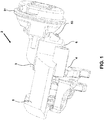
FIGURE 1 is an isometric view of a disc brake according to the present invention; -
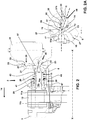
FIGURE 2 is a vertical cross section through the disc brake ofFigure 1 through a circumferential midpoint thereof; -
FIGURE 2A is an enlarged view of the portion labelled Detail A ofFigure 2 ; -
FIGURE 3 is a view of the inboard face of the disc brake ofFigure 1 ; -
FIGURE 4 is a vertical cross-section through an adjuster mechanism of a disc brake according to another embodiment of the present invention; and -
FIGURE 5A is an enlarged view similar toFigure 2A , but of an alternative embodiment. -
Figures 1 ,2 and3 illustrate adisc brake 2. The disc brake incorporates an actuating mechanism comprising a single piston suitable for a commercial vehicle. This type of brake is particularly, but not exclusively, suitable for lighter duty heavy vehicles, for example smaller trucks, or a trailer of a tractor-trailer combination. - Various orientations of the disc brake are described. In particular the directions inboard and outboard refer to the typical orientation of the disc brake when fitted to a vehicle. In this orientation the brake pad closest to the centre of the vehicle is the pad directly actuated by an actuation mechanism and being the inboard pad, and the outboard pad being one mounted to a bridge portion of the caliper. Thus inboard can be equated with an actuating side of the disc brake, and outboard with a reaction side. The terms radial, circumferential, tangential and chordal describe orientations with respect to the brake rotor. The terms vertical and horizontal describe orientations with the disc brake mounted uppermost on an axle, whereas it will be appreciated that in use such a disc brake may adopt any axle orientation depending upon packaging requirements of the vehicle.
- The
disc brake 2 comprises acaliper 3 having ahousing 6 to accommodate the actuation mechanism and which is slideably mounted on acarrier 4 for movement in an inboard-outboard direction. - As can be seen from the view in
Figure 3 , thecaliper 3 can slide on thecarrier 4, by way of first andsecond guide pins 3a, 3b. - An
inboard brake pad 11a comprises a layer of friction material and is arranged so that the friction material faces a brake rotor 10 (also known as a brake disc). Theinboard pad 11a is mounted to a brake pad support arrangement in the form of a recess of thecarrier 4. Thebrake pad 11a is moveable in the direction of arrow 14 (seeFigure 2 ) against the brake rotor. Therotor 10 rotates about an axis X-X. - An
outboard pad 11b, also with a layer of friction material, is also provided. Theoutboard pad 11b is mounted to a further brake support arrangement in the form of a further recess in the carrier outboard of therotor 10. - Suitable means are provided to urge an
outboard brake pad 11b against the opposite side of therotor 10. In this embodiment, such means comprises abridge 5 arranged so as to straddle therotor 10 and to transmit the reaction force from aninboard operating shaft 21 to theoutboard pad 11b. In this embodiment thehousing 6 andbridge 5 are manufactured as a single monolithic casting, but in other embodiments, the bridge may be bolted or otherwise secured to the housing. - With reference to the cross-section of
Figure 2 , the inboard actuation mechanism comprises asingle brake piston 15, moveable in the direction of arrow 14 (i.e. inboard-outboard) relative to therotor 10. - In order to urge the piston assembly in the direction of
arrow 14, the operatingshaft 21 is pivoted about curved surfaces 23 (one visible) which are located along atransverse axis 28 in corresponding bearing surfaces 27 provided in the inboard wall of thehousing 6, eachsurface 27 being curved to accept thecurved surface 23. Concave surfaces (not visible) of the operatingshaft 21 are located opposite thesurfaces 23 to receive rollers (not visible). The rollers define an axis, which is parallel to and offset from theaxis 28. The rollers engage ayoke 20, which in turn is arranged to actuate thepiston 15. - The operating
shaft 21 further comprises alever 24 having apocket 25 adapted to receive anoutput push rod 29 of a brake actuator 31 (e.g. an air chamber). Thelever 24 is, in this embodiment, shaped as an inverted "U" and the line of action of the brake actuator (from pocket 25) is substantially over the line of action of thepiston 15. - The
yoke 20 has a throughbore 43 extending axially through its centre to receive thepiston 15. - Application of a force in the direction of arrow 26 causes pivoting movement of the operating
shaft 21 about the curved surfaces. The offset axes of the operatingshaft 21 and rollers cause theyoke 20 to move in the direction of thepiston 15, contacting thepiston 15 and causing thepiston 15 to urge the friction material 13 of thebrake pad 11a directly against therotor 10. A reaction force from the operatingshaft 21 is transmitted to the bearingsurface 27 of thecaliper 3 via thesurfaces 23 and is then transmitted to theoutboard pad 11b via thebridge 5, with the friction material 13 of the outboard pad l1b being urged against therotor 10, such that thepads rotor 10 and effect braking through a frictional brake force. - In other embodiments, such as that described below, the arrangement may be reversed with the rollers being in contact with the
housing 6, and thecurved surface 23 being located in contact with theyoke 20. - A
wear adjuster mechanism 30 to maintain a desired running clearance between therotor 10 andpads - Generally, the operating
shaft 21 is connected to a torque limiting clutch, which is friction clutch 41 (comprising interleaved input and output clutch plates) in this embodiment and a one-way clutch 39 (a wrap spring in this embodiment) to transfer any rotation of the operating shaft beyond a predetermined amount to the piston up to a predetermined level of torque. - Alternatively a ball and ramp arrangement could be used for the torque limiting clutch instead of a friction clutch, as is known in the art. Alternatives to a wrap spring may also be used as the one-way clutch.
- The
piston 15 comprises arotatable portion 15a and anon-rotatable portion 15b. In this embodiment the rotatable portion is anouter piston 15a having an internal female thread, and the non-rotatable portion is aninner piston 15b, having a complimentary external male thread. Therefore, in this embodiment theinner piston 15b is located within theouter piston 15a. In this embodiment thewrap spring 39 directly drives theouter piston 15a. The inner piston is restrained from rotation, e.g. by being keyed to theinboard brake pad 11a. - The components above, that are located between the operating shaft and inner and outer piston, define a transmission path of the
wear adjuster mechanism 30 and take drive from the pivoting of the operating shaft. - The
outer piston 15a is configured to rotate during an adjustment operation, to cause thepiston 15 to advance in the direction of theinboard brake pad 11a. - The
wear adjuster mechanism 30 additionally comprises apressure plate 45 located outboard and engaging thefriction clutch 41. An outboard face of thepressure plate 45 is acted on by acompression spring 47, thecompression spring 47 being arranged concentrically with the piston, and generates the required amount of friction to control the torque at which the friction clutch 41 slips. In this embodiment thecompression spring 47 also acts as a return spring to return thepiston 15 and operatingshaft 21 to their brakes-off positions when a braking operation is complete andpushrod 29 is retracted. - In order to maintain a desired running clearance between the brake pads and rotor, the
wear adjuster mechanism 30 is required to periodically advance theinboard brake pad 11a towards therotor 10 to account for the loss of friction material 13, and to a lesser extent, loss of material from the face of therotor 10, due to wear. - A predetermined amount of play or backlash is provided in the transmission path. In a normal braking operation in which the running clearance is within the desired parameters, as the operating
shaft 21 pivots, the play in the system means that no adjustment will occur. - If the running clearance is however greater than the desired range, the aforesaid play is taken up. Whilst there is excess running clearance to be taken up, this rotation is transmitted via
friction clutch 41 to thewrap spring 39, causing thewrap spring 39 to rotate around theouter piston 15 in a direction which causes thewrap spring 39 to tighten, transmitting the rotation from the drive drum 35 to the driven drum 37. In other embodiments the position of the torque limiting clutch and one way clutch in the adjustment transmission path may be reversed. - Since the
inner piston 15b is restrained from rotation by the engagement with thebrake pad 11a, this causes a lengthening of thepiston 15 to reduce the running clearance. At the point at which the friction material 13 comes into full contact with therotor 10, the torque passing through the adjustment mechanism increases. When this torque increases to a level that is higher than the maximum torque value of thefriction clutch 41, the friction clutch 41 slips and further extension of theouter piston 15 is prevented. Once the braking operation ceases, thecompression spring 47 acts to urge the operatingshaft 21 back to its rest position. A corresponding retraction of theinner piston 15b is prevented since thewrap spring 39 relaxes and does not transmit a reverse rotation to theouter piston 15a. - Once the friction material 13 has worn to its design limit, it is necessary for the
brake pads piston 15 to be rewound back to its retracted position. - To this end, a
manual adjuster apparatus 50 incorporating afirst element 51b and asecond element 51a is provided. The first element, at least, is a shaft. Thesecond element 51a andfirst element 51b are arranged end-to-end. Auniversal joint 70 drivingly connects the second element and the first element, and thefirst element 51b extends away from thesecond element 51a at an angle that is oblique to the axis of the second element. - The
first element 51b has ahex head 53 or other suitable interface provided at the outer (user accessible) longitudinal end thereof. Thehex head 53 has a cover (not visible), which is located over thehex head 53. In this embodiment, the cover is a rubber cap. The cover can be removed by a user when access to thehex head 53 is required. A spanner, wrench or other suitable tool may be attached to thehex head 53 to effect the rewinding operation. - The first element extends through a
bore 55 provided in aninboard wall 57 of thecaliper housing 6 so that thehead 53 is accessible from an inboard face of the exterior of the caliper housing. - It can be seen that the
first element 51b extends at a radially inward angle α i.e. it is angled towards the rotational axis X-X of therotor 10. As can be seen inFigure 2 a radially inward angle directs thehead 53 of thefirst element 51a away from theair actuator 31, when, as depicted it is mounted on theinboard wall 57 of thecaliper housing 6. As a result more space is available for a tool to be attached to thehead 53 to rotate themanual adjuster shaft 51, as compared to a shaft that extends inboard in alignment with the axis of thepiston 15. - The oblique angle α between the
first element 51b andsecond element 51a may be any angle that is practically achievable by the form of universal joint that is used. For example it may be between 1 and 60 degrees from the axis of thepiston 15, but more typically between 5 and 45 degrees. In alternative embodiments, the angle may be in a circumferential direction, or a combination of circumferential and radial. The radial angle may be radially outwards. - In this embodiment, the
wall 57 of thecaliper housing 6 also acts as a plain bearing for thefirst element 51b such that a portion of the first element is a journal for the bearing, and the wall assists in maintaining the desired angle of thefirst element 51b. - In addition, an interface between the
first element 51b and theinboard wall 57 of the housing is arranged to restrict movement of the first element axially outboard. In this embodiment acollar 59 is provided around the first element that abuts the outboard face of theinboard wall 57 to restrict outboard movement of the first element. Alternatively other suitable forms such as snap rings may be used as a stop and may be provided on the inboard face to prevent outboard movement too. - In particular, the interface, to restrict movement inboard, may be utilised to assist installation of the manual adjuster shaft, e.g. if the
universal joint 70 is to be attached to thefirst element 51b once the first element has been inserted through theinboard wall 57. - In this embodiment, the
second element 51a is in substantially parallel alignment with an axis of therotatable portion 15a of thepiston 15. This enables thesecond element 51a to drivingly mesh more easily with therotatable portion 15a. - In this embodiment, the
second element 51a is also coaxially aligned with therotatable portion 15a and is additionally located partially within thepiston 15. Specifically, therotatable portion 15a has abore 18 in aninboard end wall 17 thereof that has a non-circular profile. Thesecond element 51a has a corresponding external profile such that direct driving engagement is provided, but relative axial movement is permitted (e.g. during brake application when the piston moves outboard). As in this embodiment, the outboard end of thesecond element 51a may be enlarged to restrict relative axial motion. - The universal joint 70 depicted in
Figures 2 and 2A comprises aball head 72 andsleeve 74 arrangement. Theball head 72 andsleeve 74 have a non-circular profile, for example a hex profile. The shape of the ball head and adjacent thinned portion of the element permit a degree of articulation within the sleeve, but the hex head nevertheless causes torque to be transmitted between the two components. In other embodiments the location of sleeve and head may be reversed. As the usage of the manual adjuster apparatus is limited over the life of a disc brake, the robust nature of this arrangement is advantageous, and wear of the contacting surfaces is minimal. - In alternative embodiments, alternative forms of universal joint may be used, such as a coiled flexible joint, Hookes joint or a constant velocity joint.
- Located outboard of the cover, is a sealing
collar 56. The sealingcollar 56 is generally annular and is configured to locate on thefirst element 51 adjacent the cover 54. Themanual adjuster apparatus 50 is configured such that it can freely rotate within thecollar 56 e.g. by use of one or more of suitable lubrication, coatings such as PTFE, or by the collar incorporating a lip seal that minimises the contact areas between the collar and shaft. The base of the sealing member engages with thecollar 56 to substantially seal lubricant within thehousing 6 of the brake and help prevent foreign material from contaminating thehousing 6 of the brake. -
Figure 4 illustrates an adjuster mechanism incorporating a manual adjuster apparatus of a disc brake according to a second embodiment of the present invention. Like components are denoted by like numerals but with the addition of the prefix "1". - The
wear adjuster mechanism 130 of this embodiment is mounted in a caliper housing similar to that of the first embodiment but the mechanism differs from that of the first embodiment in that therotatable portion 115a of thepiston 115 is concentrically within thenon-rotatable portion 115b. In other words therotatable portion 115a is an inner piston and thenon-rotatable portion 115b is an outer piston. - The
rotatable portion 115a is hollow and, consequently, thewear adjuster mechanism 130 of thefriction clutch 141 and wrapspring 139 one way clutch are mounted within thepiston 115 and the output plates of the friction clutch drive the inner surface of therotatable portion 115a. In addition in this embodiment the orientation of thecurved surface 123 of the operatingshaft 121 androllers 122 is reversed. - The
manual rewind apparatus 150 is mounted concentrically and radially inwardly with respect to the components of theadjustment mechanism 130 and thesecond element 151a extends through the radial centre of the wear adjuster mechanism. At the outboard end longitudinally opposite thehex head 153, a piston engagingend piece 158 is mounted on the second element 151 and drivingly engages therotatable portion 115a viachannels 142 of therotatable portion 115a. - In use during manual adjustment therefore, a user rotates the
hex head 153 to rotate themanual adjuster apparatus 150. Due to the engagement between theend piece 158 and thechannels 142 of therotatable portion 115a, therotatable portion 115a is caused to rotate, rewinding thepiston 115 back to its original retracted position. -
Figure 5A illustrates adisc brake 202 incorporating auniversal joint 270 according to another embodiment. Like parts are denoted by like numerals as compared to the first embodiment but with the addition of the prefix '2'.Figure 5A is an enlarged view of the same area of the disc brake asFigure 2A and only differences between the two are discussed. - In this embodiment the second element is omitted such that the
universal joint 270 is provided by thefirst element 251b directly meshing with the rotatable,outer portion 215a of the piston 215. This is achieved in this embodiment by providing theball head 272 on thefirst element 251b and thesleeve 274 on therotatable portion 215a of the piston. Therotatable portion 215a moves axially when the disc brake is applied (of the order of 1-3mm of movement to take up the running clearance). Thefirst element 251b is fixed axially and so theball head 272 is able to slide within thesleeve 274. However, thenon-circular sleeve 274 andhead 272 enable the transmission of drive from thehead 253 as before. - It will be appreciated that numerous changes may be made within the scope of the present invention. For example, the manual adjuster mechanism may be laterally offset from the axis of the piston and the second element may comprise a gear arranged to drive the piston or a sprocket and chain or pulley and belt arrangement. The universal joint may be arranged to permit axial movement between the first and second elements. In other embodiments, more than one universal joint may be utilised.
Claims (15)
- A disc brake for heavy vehicles, the disc brake comprising:a housing;a piston mounted within the housing for applying an actuating force to a brake pad, the piston having a rotatable portion to adjust the running clearance between a brake disc and the brake pad and the rotatable portion defining an axis of rotation;a manual adjuster apparatus drivingly connected to the rotatable portion;wherein the manual adjuster apparatus comprises a first element and a universal joint drivingly connecting the first element to the rotatable portion such that the first element extends away from the rotatable portion at an angle that is oblique to the axis of rotation.
- The disc brake of claim 1 wherein the manual adjuster apparatus further comprises a second element, wherein the second element drivingly connects the universal joint to the rotatable portion.
- The disc brake of claim 1 or claim 2 wherein the first element has a head remote from the universal joint, the head being accessible from an exterior of the housing to apply torque to the apparatus.
- The disc brake of claim 3 wherein the head is accessible from an inboard face of the exterior.
- The disc brake of any preceding claim wherein the first element extends at a radially inward angle.
- The disc brake of any preceding claim wherein a wall of the housing is a bearing for the first element and the first element is journalled thereto.
- The disc brake of claim 6 wherein the bearing is arranged to maintain the angle.
- The disc brake of any preceding claim wherein an interface between the first element and a wall of the housing is arranged to restrict movement of the first element in at least a first axial direction.
- The disc brake of any of claims 2 to 8 wherein the second element is in substantially parallel alignment with an axis of the rotatable portion.
- The disc brake of any of claims 2 to 9 wherein the second element is located at least partially within the piston.
- The disc brake of any of claims 2 to 10 wherein the second element is in direct driving engagement with the rotatable portion.
- The disc brake of any preceding claim, wherein the first element is a rotatable shaft.
- The disc brake of any preceding claim, wherein the oblique angle is between 1 and 60 degrees from the axis of the piston, preferably between 5 and 45 degrees from the axis of the piston.
- The disc brake of any preceding claim wherein the universal joint comprises a ball head and sleeve arrangement or wherein the universal joint comprises a coiled flexible joint.
- The disc brake of any preceding claim wherein an axis of the manual adjuster apparatus is on substantially the same radial plane as a line of action of a push rod of an actuator of the disc brake.
Priority Applications (3)
| Application Number | Priority Date | Filing Date | Title |
|---|---|---|---|
| EP17188746.6A EP3450788B1 (en) | 2017-08-31 | 2017-08-31 | A disc brake |
| US16/055,469 US10527118B2 (en) | 2017-08-31 | 2018-08-06 | Disc brake |
| CN201810932809.6A CN109424676B (en) | 2017-08-31 | 2018-08-16 | Disc brake |
Applications Claiming Priority (1)
| Application Number | Priority Date | Filing Date | Title |
|---|---|---|---|
| EP17188746.6A EP3450788B1 (en) | 2017-08-31 | 2017-08-31 | A disc brake |
Publications (2)
| Publication Number | Publication Date |
|---|---|
| EP3450788A1 true EP3450788A1 (en) | 2019-03-06 |
| EP3450788B1 EP3450788B1 (en) | 2020-10-21 |
Family
ID=59745791
Family Applications (1)
| Application Number | Title | Priority Date | Filing Date |
|---|---|---|---|
| EP17188746.6A Active EP3450788B1 (en) | 2017-08-31 | 2017-08-31 | A disc brake |
Country Status (3)
| Country | Link |
|---|---|
| US (1) | US10527118B2 (en) |
| EP (1) | EP3450788B1 (en) |
| CN (1) | CN109424676B (en) |
Families Citing this family (8)
| Publication number | Priority date | Publication date | Assignee | Title |
|---|---|---|---|---|
| CN109281961B (en) * | 2017-07-21 | 2021-03-12 | 英国美瑞特重型车制动系统有限公司 | Disc brake |
| EP3564549A1 (en) * | 2018-04-30 | 2019-11-06 | Meritor Heavy Vehicle Braking Systems (UK) Limited | A disc brake |
| EP3431799B1 (en) * | 2017-07-21 | 2022-05-25 | Meritor Heavy Vehicle Braking Systems (UK) Limited | A disc brake |
| EP3564553B1 (en) * | 2018-04-30 | 2022-06-08 | Meritor Heavy Vehicle Braking Systems (UK) Limited | An adjuster mechanism |
| EP3783242B1 (en) * | 2019-08-22 | 2022-12-28 | ZF CV Systems Global GmbH | Disc brake for vehicles, especially for commercial vehicles, with an electromechanical actuator |
| US11608045B2 (en) | 2020-09-16 | 2023-03-21 | Arvinmeritor Technology, Llc | System and method of checking sealing of a brake caliper housing |
| US11718283B2 (en) | 2020-09-18 | 2023-08-08 | Arvinmeritor Technology, Llc | Brake assembly having a sensor |
| US11821482B2 (en) * | 2020-09-18 | 2023-11-21 | Arvinmeritor Technology, Llc | Brake assembly and method of adjustment |
Citations (4)
| Publication number | Priority date | Publication date | Assignee | Title |
|---|---|---|---|---|
| EP0730107A2 (en) | 1995-03-02 | 1996-09-04 | PERROT BREMSEN GmbH | Disc brake |
| EP2602506A1 (en) * | 2011-12-05 | 2013-06-12 | Meritor Heavy Vehicle Braking Systems (UK) Limited | Adjuster system |
| US20160215835A1 (en) * | 2015-01-28 | 2016-07-28 | Meritor Heavy Vehicle Braking Systems (Uk) Limited | Disc brake |
| EP3179127A1 (en) * | 2015-12-10 | 2017-06-14 | Meritor Heavy Vehicle Braking Systems (UK) Limited | Adjuster assembly |
Family Cites Families (8)
| Publication number | Priority date | Publication date | Assignee | Title |
|---|---|---|---|---|
| GB1191263A (en) * | 1966-08-13 | 1970-05-13 | Dunlop Co Ltd | Improvements in Disc Brakes |
| US3901357A (en) * | 1974-07-01 | 1975-08-26 | Bendix Corp | Automatic slack adjuster |
| US4503947A (en) * | 1982-11-01 | 1985-03-12 | Allied Corporation | Disc brake and protective boot therefor |
| US4499976A (en) * | 1983-06-16 | 1985-02-19 | Rockwell International Corporation | Slack adjuster for a disc brake |
| DE3332548A1 (en) * | 1983-09-09 | 1985-03-28 | Alfred Teves Gmbh, 6000 Frankfurt | Immobilisable fixed-calliper disc brake |
| FR2573498B1 (en) * | 1984-11-21 | 1987-02-27 | Bendix France | DISC BRAKE |
| WO2014115874A1 (en) * | 2013-01-25 | 2014-07-31 | 株式会社アドヴィックス | Vehicle electric braking device |
| CN203627611U (en) * | 2013-11-28 | 2014-06-04 | 重庆建设摩托车股份有限公司 | Piston pushing mechanism of motorcycle composite braking system |
-
2017
- 2017-08-31 EP EP17188746.6A patent/EP3450788B1/en active Active
-
2018
- 2018-08-06 US US16/055,469 patent/US10527118B2/en active Active
- 2018-08-16 CN CN201810932809.6A patent/CN109424676B/en active Active
Patent Citations (4)
| Publication number | Priority date | Publication date | Assignee | Title |
|---|---|---|---|---|
| EP0730107A2 (en) | 1995-03-02 | 1996-09-04 | PERROT BREMSEN GmbH | Disc brake |
| EP2602506A1 (en) * | 2011-12-05 | 2013-06-12 | Meritor Heavy Vehicle Braking Systems (UK) Limited | Adjuster system |
| US20160215835A1 (en) * | 2015-01-28 | 2016-07-28 | Meritor Heavy Vehicle Braking Systems (Uk) Limited | Disc brake |
| EP3179127A1 (en) * | 2015-12-10 | 2017-06-14 | Meritor Heavy Vehicle Braking Systems (UK) Limited | Adjuster assembly |
Also Published As
| Publication number | Publication date |
|---|---|
| US10527118B2 (en) | 2020-01-07 |
| CN109424676A (en) | 2019-03-05 |
| CN109424676B (en) | 2020-07-10 |
| US20190063530A1 (en) | 2019-02-28 |
| EP3450788B1 (en) | 2020-10-21 |
Similar Documents
| Publication | Publication Date | Title |
|---|---|---|
| US10527118B2 (en) | Disc brake | |
| CN109281960B (en) | Disc brake | |
| CA2103080C (en) | Brake lever for an s-cam automotive drum brake | |
| US3949840A (en) | Cam brake automatic slack adjusting mechanism | |
| US4351419A (en) | Automatic slack adjuster | |
| US10323707B2 (en) | Vehicle disk brake | |
| US11173889B2 (en) | Disc brake assembly | |
| US4394890A (en) | Automatic slack adjuster | |
| EP3862591B1 (en) | An actuation mechanism | |
| US4487295A (en) | Disc brake caliper with integral parking brake | |
| EP3564553B1 (en) | An adjuster mechanism | |
| US20110203885A1 (en) | Disc Brake Adjustment Device Having a Blocking Device | |
| US10598238B2 (en) | Slack adjuster for a drum brake of a vehicle air braking system | |
| JPH026932B2 (en) | ||
| EP0216986B1 (en) | Brake actuator | |
| EP3431798B1 (en) | A disc brake | |
| CA1196296A (en) | Automatic brake adjusting mechanism | |
| GB1602068A (en) | Pressure medium operable disc brakes | |
| EP3431801B1 (en) | A disc brake | |
| EP3431803A1 (en) | A disc brake |
Legal Events
| Date | Code | Title | Description |
|---|---|---|---|
| PUAI | Public reference made under article 153(3) epc to a published international application that has entered the european phase |
Free format text: ORIGINAL CODE: 0009012 |
|
| STAA | Information on the status of an ep patent application or granted ep patent |
Free format text: STATUS: THE APPLICATION HAS BEEN PUBLISHED |
|
| AK | Designated contracting states |
Kind code of ref document: A1 Designated state(s): AL AT BE BG CH CY CZ DE DK EE ES FI FR GB GR HR HU IE IS IT LI LT LU LV MC MK MT NL NO PL PT RO RS SE SI SK SM TR |
|
| AX | Request for extension of the european patent |
Extension state: BA ME |
|
| STAA | Information on the status of an ep patent application or granted ep patent |
Free format text: STATUS: REQUEST FOR EXAMINATION WAS MADE |
|
| 17P | Request for examination filed |
Effective date: 20190829 |
|
| RBV | Designated contracting states (corrected) |
Designated state(s): AL AT BE BG CH CY CZ DE DK EE ES FI FR GB GR HR HU IE IS IT LI LT LU LV MC MK MT NL NO PL PT RO RS SE SI SK SM TR |
|
| RIC1 | Information provided on ipc code assigned before grant |
Ipc: F16D 55/226 20060101AFI20200214BHEP |
|
| GRAP | Despatch of communication of intention to grant a patent |
Free format text: ORIGINAL CODE: EPIDOSNIGR1 |
|
| STAA | Information on the status of an ep patent application or granted ep patent |
Free format text: STATUS: GRANT OF PATENT IS INTENDED |
|
| INTG | Intention to grant announced |
Effective date: 20200515 |
|
| GRAS | Grant fee paid |
Free format text: ORIGINAL CODE: EPIDOSNIGR3 |
|
| GRAA | (expected) grant |
Free format text: ORIGINAL CODE: 0009210 |
|
| STAA | Information on the status of an ep patent application or granted ep patent |
Free format text: STATUS: THE PATENT HAS BEEN GRANTED |
|
| AK | Designated contracting states |
Kind code of ref document: B1 Designated state(s): AL AT BE BG CH CY CZ DE DK EE ES FI FR GB GR HR HU IE IS IT LI LT LU LV MC MK MT NL NO PL PT RO RS SE SI SK SM TR |
|
| REG | Reference to a national code |
Ref country code: GB Ref legal event code: FG4D |
|
| REG | Reference to a national code |
Ref country code: CH Ref legal event code: EP |
|
| REG | Reference to a national code |
Ref country code: IE Ref legal event code: FG4D |
|
| REG | Reference to a national code |
Ref country code: DE Ref legal event code: R096 Ref document number: 602017025752 Country of ref document: DE |
|
| REG | Reference to a national code |
Ref country code: AT Ref legal event code: REF Ref document number: 1326137 Country of ref document: AT Kind code of ref document: T Effective date: 20201115 |
|
| REG | Reference to a national code |
Ref country code: SE Ref legal event code: TRGR |
|
| REG | Reference to a national code |
Ref country code: AT Ref legal event code: MK05 Ref document number: 1326137 Country of ref document: AT Kind code of ref document: T Effective date: 20201021 |
|
| REG | Reference to a national code |
Ref country code: NL Ref legal event code: MP Effective date: 20201021 |
|
| PG25 | Lapsed in a contracting state [announced via postgrant information from national office to epo] |
Ref country code: FI Free format text: LAPSE BECAUSE OF FAILURE TO SUBMIT A TRANSLATION OF THE DESCRIPTION OR TO PAY THE FEE WITHIN THE PRESCRIBED TIME-LIMIT Effective date: 20201021 Ref country code: GR Free format text: LAPSE BECAUSE OF FAILURE TO SUBMIT A TRANSLATION OF THE DESCRIPTION OR TO PAY THE FEE WITHIN THE PRESCRIBED TIME-LIMIT Effective date: 20210122 Ref country code: RS Free format text: LAPSE BECAUSE OF FAILURE TO SUBMIT A TRANSLATION OF THE DESCRIPTION OR TO PAY THE FEE WITHIN THE PRESCRIBED TIME-LIMIT Effective date: 20201021 Ref country code: PT Free format text: LAPSE BECAUSE OF FAILURE TO SUBMIT A TRANSLATION OF THE DESCRIPTION OR TO PAY THE FEE WITHIN THE PRESCRIBED TIME-LIMIT Effective date: 20210222 Ref country code: NO Free format text: LAPSE BECAUSE OF FAILURE TO SUBMIT A TRANSLATION OF THE DESCRIPTION OR TO PAY THE FEE WITHIN THE PRESCRIBED TIME-LIMIT Effective date: 20210121 |
|
| REG | Reference to a national code |
Ref country code: LT Ref legal event code: MG4D |
|
| PG25 | Lapsed in a contracting state [announced via postgrant information from national office to epo] |
Ref country code: BG Free format text: LAPSE BECAUSE OF FAILURE TO SUBMIT A TRANSLATION OF THE DESCRIPTION OR TO PAY THE FEE WITHIN THE PRESCRIBED TIME-LIMIT Effective date: 20210121 Ref country code: LV Free format text: LAPSE BECAUSE OF FAILURE TO SUBMIT A TRANSLATION OF THE DESCRIPTION OR TO PAY THE FEE WITHIN THE PRESCRIBED TIME-LIMIT Effective date: 20201021 Ref country code: PL Free format text: LAPSE BECAUSE OF FAILURE TO SUBMIT A TRANSLATION OF THE DESCRIPTION OR TO PAY THE FEE WITHIN THE PRESCRIBED TIME-LIMIT Effective date: 20201021 Ref country code: IS Free format text: LAPSE BECAUSE OF FAILURE TO SUBMIT A TRANSLATION OF THE DESCRIPTION OR TO PAY THE FEE WITHIN THE PRESCRIBED TIME-LIMIT Effective date: 20210221 Ref country code: ES Free format text: LAPSE BECAUSE OF FAILURE TO SUBMIT A TRANSLATION OF THE DESCRIPTION OR TO PAY THE FEE WITHIN THE PRESCRIBED TIME-LIMIT Effective date: 20201021 Ref country code: AT Free format text: LAPSE BECAUSE OF FAILURE TO SUBMIT A TRANSLATION OF THE DESCRIPTION OR TO PAY THE FEE WITHIN THE PRESCRIBED TIME-LIMIT Effective date: 20201021 |
|
| PG25 | Lapsed in a contracting state [announced via postgrant information from national office to epo] |
Ref country code: HR Free format text: LAPSE BECAUSE OF FAILURE TO SUBMIT A TRANSLATION OF THE DESCRIPTION OR TO PAY THE FEE WITHIN THE PRESCRIBED TIME-LIMIT Effective date: 20201021 Ref country code: NL Free format text: LAPSE BECAUSE OF FAILURE TO SUBMIT A TRANSLATION OF THE DESCRIPTION OR TO PAY THE FEE WITHIN THE PRESCRIBED TIME-LIMIT Effective date: 20201021 |
|
| REG | Reference to a national code |
Ref country code: DE Ref legal event code: R097 Ref document number: 602017025752 Country of ref document: DE |
|
| PG25 | Lapsed in a contracting state [announced via postgrant information from national office to epo] |
Ref country code: SM Free format text: LAPSE BECAUSE OF FAILURE TO SUBMIT A TRANSLATION OF THE DESCRIPTION OR TO PAY THE FEE WITHIN THE PRESCRIBED TIME-LIMIT Effective date: 20201021 Ref country code: LT Free format text: LAPSE BECAUSE OF FAILURE TO SUBMIT A TRANSLATION OF THE DESCRIPTION OR TO PAY THE FEE WITHIN THE PRESCRIBED TIME-LIMIT Effective date: 20201021 Ref country code: EE Free format text: LAPSE BECAUSE OF FAILURE TO SUBMIT A TRANSLATION OF THE DESCRIPTION OR TO PAY THE FEE WITHIN THE PRESCRIBED TIME-LIMIT Effective date: 20201021 Ref country code: CZ Free format text: LAPSE BECAUSE OF FAILURE TO SUBMIT A TRANSLATION OF THE DESCRIPTION OR TO PAY THE FEE WITHIN THE PRESCRIBED TIME-LIMIT Effective date: 20201021 Ref country code: SK Free format text: LAPSE BECAUSE OF FAILURE TO SUBMIT A TRANSLATION OF THE DESCRIPTION OR TO PAY THE FEE WITHIN THE PRESCRIBED TIME-LIMIT Effective date: 20201021 Ref country code: RO Free format text: LAPSE BECAUSE OF FAILURE TO SUBMIT A TRANSLATION OF THE DESCRIPTION OR TO PAY THE FEE WITHIN THE PRESCRIBED TIME-LIMIT Effective date: 20201021 |
|
| PLBE | No opposition filed within time limit |
Free format text: ORIGINAL CODE: 0009261 |
|
| STAA | Information on the status of an ep patent application or granted ep patent |
Free format text: STATUS: NO OPPOSITION FILED WITHIN TIME LIMIT |
|
| PG25 | Lapsed in a contracting state [announced via postgrant information from national office to epo] |
Ref country code: DK Free format text: LAPSE BECAUSE OF FAILURE TO SUBMIT A TRANSLATION OF THE DESCRIPTION OR TO PAY THE FEE WITHIN THE PRESCRIBED TIME-LIMIT Effective date: 20201021 |
|
| 26N | No opposition filed |
Effective date: 20210722 |
|
| PG25 | Lapsed in a contracting state [announced via postgrant information from national office to epo] |
Ref country code: IT Free format text: LAPSE BECAUSE OF FAILURE TO SUBMIT A TRANSLATION OF THE DESCRIPTION OR TO PAY THE FEE WITHIN THE PRESCRIBED TIME-LIMIT Effective date: 20201021 Ref country code: AL Free format text: LAPSE BECAUSE OF FAILURE TO SUBMIT A TRANSLATION OF THE DESCRIPTION OR TO PAY THE FEE WITHIN THE PRESCRIBED TIME-LIMIT Effective date: 20201021 |
|
| PG25 | Lapsed in a contracting state [announced via postgrant information from national office to epo] |
Ref country code: SI Free format text: LAPSE BECAUSE OF FAILURE TO SUBMIT A TRANSLATION OF THE DESCRIPTION OR TO PAY THE FEE WITHIN THE PRESCRIBED TIME-LIMIT Effective date: 20201021 |
|
| REG | Reference to a national code |
Ref country code: CH Ref legal event code: PL |
|
| PG25 | Lapsed in a contracting state [announced via postgrant information from national office to epo] |
Ref country code: MC Free format text: LAPSE BECAUSE OF FAILURE TO SUBMIT A TRANSLATION OF THE DESCRIPTION OR TO PAY THE FEE WITHIN THE PRESCRIBED TIME-LIMIT Effective date: 20201021 |
|
| REG | Reference to a national code |
Ref country code: BE Ref legal event code: MM Effective date: 20210831 |
|
| GBPC | Gb: european patent ceased through non-payment of renewal fee |
Effective date: 20210831 |
|
| PG25 | Lapsed in a contracting state [announced via postgrant information from national office to epo] |
Ref country code: LI Free format text: LAPSE BECAUSE OF NON-PAYMENT OF DUE FEES Effective date: 20210831 Ref country code: CH Free format text: LAPSE BECAUSE OF NON-PAYMENT OF DUE FEES Effective date: 20210831 |
|
| PG25 | Lapsed in a contracting state [announced via postgrant information from national office to epo] |
Ref country code: IS Free format text: LAPSE BECAUSE OF FAILURE TO SUBMIT A TRANSLATION OF THE DESCRIPTION OR TO PAY THE FEE WITHIN THE PRESCRIBED TIME-LIMIT Effective date: 20210221 Ref country code: LU Free format text: LAPSE BECAUSE OF NON-PAYMENT OF DUE FEES Effective date: 20210831 |
|
| PG25 | Lapsed in a contracting state [announced via postgrant information from national office to epo] |
Ref country code: IE Free format text: LAPSE BECAUSE OF NON-PAYMENT OF DUE FEES Effective date: 20210831 Ref country code: GB Free format text: LAPSE BECAUSE OF NON-PAYMENT OF DUE FEES Effective date: 20210831 Ref country code: BE Free format text: LAPSE BECAUSE OF NON-PAYMENT OF DUE FEES Effective date: 20210831 |
|
| PG25 | Lapsed in a contracting state [announced via postgrant information from national office to epo] |
Ref country code: CY Free format text: LAPSE BECAUSE OF FAILURE TO SUBMIT A TRANSLATION OF THE DESCRIPTION OR TO PAY THE FEE WITHIN THE PRESCRIBED TIME-LIMIT Effective date: 20201021 |
|
| P01 | Opt-out of the competence of the unified patent court (upc) registered |
Effective date: 20230531 |
|
| PG25 | Lapsed in a contracting state [announced via postgrant information from national office to epo] |
Ref country code: HU Free format text: LAPSE BECAUSE OF FAILURE TO SUBMIT A TRANSLATION OF THE DESCRIPTION OR TO PAY THE FEE WITHIN THE PRESCRIBED TIME-LIMIT; INVALID AB INITIO Effective date: 20170831 |
|
| PGFP | Annual fee paid to national office [announced via postgrant information from national office to epo] |
Ref country code: SE Payment date: 20230827 Year of fee payment: 7 Ref country code: FR Payment date: 20230825 Year of fee payment: 7 Ref country code: DE Payment date: 20230829 Year of fee payment: 7 |