EP3450737A1 - Liaison cachée pour inverseur de poussée de capot de translation et procédé de production - Google Patents
Liaison cachée pour inverseur de poussée de capot de translation et procédé de production Download PDFInfo
- Publication number
- EP3450737A1 EP3450737A1 EP18190869.0A EP18190869A EP3450737A1 EP 3450737 A1 EP3450737 A1 EP 3450737A1 EP 18190869 A EP18190869 A EP 18190869A EP 3450737 A1 EP3450737 A1 EP 3450737A1
- Authority
- EP
- European Patent Office
- Prior art keywords
- blocker door
- transcowl
- thrust reverser
- linkage rod
- pivot axis
- Prior art date
- Legal status (The legal status is an assumption and is not a legal conclusion. Google has not performed a legal analysis and makes no representation as to the accuracy of the status listed.)
- Granted
Links
Images


Classifications
-
- F—MECHANICAL ENGINEERING; LIGHTING; HEATING; WEAPONS; BLASTING
- F02—COMBUSTION ENGINES; HOT-GAS OR COMBUSTION-PRODUCT ENGINE PLANTS
- F02K—JET-PROPULSION PLANTS
- F02K1/00—Plants characterised by the form or arrangement of the jet pipe or nozzle; Jet pipes or nozzles peculiar thereto
- F02K1/54—Nozzles having means for reversing jet thrust
- F02K1/76—Control or regulation of thrust reversers
- F02K1/763—Control or regulation of thrust reversers with actuating systems or actuating devices; Arrangement of actuators for thrust reversers
-
- F—MECHANICAL ENGINEERING; LIGHTING; HEATING; WEAPONS; BLASTING
- F02—COMBUSTION ENGINES; HOT-GAS OR COMBUSTION-PRODUCT ENGINE PLANTS
- F02K—JET-PROPULSION PLANTS
- F02K1/00—Plants characterised by the form or arrangement of the jet pipe or nozzle; Jet pipes or nozzles peculiar thereto
- F02K1/54—Nozzles having means for reversing jet thrust
- F02K1/56—Reversing jet main flow
- F02K1/60—Reversing jet main flow by blocking the rearward discharge by means of pivoted eyelids or clamshells, e.g. target-type reversers
- F02K1/605—Reversing jet main flow by blocking the rearward discharge by means of pivoted eyelids or clamshells, e.g. target-type reversers the aft end of the engine cowling being movable to uncover openings for the reversed flow
-
- F—MECHANICAL ENGINEERING; LIGHTING; HEATING; WEAPONS; BLASTING
- F02—COMBUSTION ENGINES; HOT-GAS OR COMBUSTION-PRODUCT ENGINE PLANTS
- F02K—JET-PROPULSION PLANTS
- F02K1/00—Plants characterised by the form or arrangement of the jet pipe or nozzle; Jet pipes or nozzles peculiar thereto
- F02K1/54—Nozzles having means for reversing jet thrust
- F02K1/56—Reversing jet main flow
- F02K1/62—Reversing jet main flow by blocking the rearward discharge by means of flaps
- F02K1/625—Reversing jet main flow by blocking the rearward discharge by means of flaps the aft end of the engine cowling being movable to uncover openings for the reversed flow
-
- F—MECHANICAL ENGINEERING; LIGHTING; HEATING; WEAPONS; BLASTING
- F02—COMBUSTION ENGINES; HOT-GAS OR COMBUSTION-PRODUCT ENGINE PLANTS
- F02K—JET-PROPULSION PLANTS
- F02K1/00—Plants characterised by the form or arrangement of the jet pipe or nozzle; Jet pipes or nozzles peculiar thereto
- F02K1/54—Nozzles having means for reversing jet thrust
- F02K1/64—Reversing fan flow
- F02K1/70—Reversing fan flow using thrust reverser flaps or doors mounted on the fan housing
- F02K1/72—Reversing fan flow using thrust reverser flaps or doors mounted on the fan housing the aft end of the fan housing being movable to uncover openings in the fan housing for the reversed flow
-
- F—MECHANICAL ENGINEERING; LIGHTING; HEATING; WEAPONS; BLASTING
- F02—COMBUSTION ENGINES; HOT-GAS OR COMBUSTION-PRODUCT ENGINE PLANTS
- F02K—JET-PROPULSION PLANTS
- F02K1/00—Plants characterised by the form or arrangement of the jet pipe or nozzle; Jet pipes or nozzles peculiar thereto
- F02K1/06—Varying effective area of jet pipe or nozzle
- F02K1/09—Varying effective area of jet pipe or nozzle by axially moving an external member, e.g. a shroud
-
- F—MECHANICAL ENGINEERING; LIGHTING; HEATING; WEAPONS; BLASTING
- F05—INDEXING SCHEMES RELATING TO ENGINES OR PUMPS IN VARIOUS SUBCLASSES OF CLASSES F01-F04
- F05D—INDEXING SCHEME FOR ASPECTS RELATING TO NON-POSITIVE-DISPLACEMENT MACHINES OR ENGINES, GAS-TURBINES OR JET-PROPULSION PLANTS
- F05D2260/00—Function
- F05D2260/50—Kinematic linkage, i.e. transmission of position
Definitions
- the present invention relates to a thrust reverser system for a turbine engine, and more particularly to a hidden linkage arrangement for a translating cowl thrust reverser system.
- turbine engines on most jet-powered aircraft include thrust reverser systems. Thrust reverser systems enhance the stopping power of the aircraft by redirecting turbine engine exhaust flow in order to generate reverse thrust.
- Traditional thrust reverser systems have two distinct operating states: a forward (or stowed) state, wherein the thrust reverser system typically forms a portion a turbine engine nacelle and forward thrust nozzle; and a reverse (or deployed) state, wherein the thrust reverser system forms a reverse flow path through which it redirects at least a portion of the engine airflow forward and radially outward, to help decelerate the aircraft.
- the transition between the forward to the reverse state may be achieved by translating a portion of the nacelle aft.
- the translating portion of the nacelle is often referred to as the translating cowl, or transcowl, and translating the transcowl aft creates an aperture in the nacelle.
- blocker doors are typically deployed synchronously with the translation of the transcowl aft. The blocker doors obstruct forward thrust and generate reverse thrust that discharges through the aperture.
- the blocker doors are pivotally mounted to the transcowl and connected to the body of the turbine engine with linkage rods. Accordingly, in these designs, the linkage rods are exposed within the engine exhaust flow path. Having the linkage rods in the engine exhaust flow path increases drag, and therefore reduces engine performance.
- a thrust reverser system for a turbine engine comprising: a stationary structure configured to be mounted to the turbine engine; a transcowl supported by the stationary structure, the transcowl creating a thrust reverser flowpath and translatable (i) axially, relative to the stationary structure, and (ii) between a first position, in which the transcowl abuts the stationary structure, and a second position, in which the transcowl is displaced from the stationary structure to form a reverse flow aperture; a blocker door pivotally mounted, at a pivot axis, to the stationary structure, the pivot axis being perpendicular to a thrust reverser centerline, the blocker door configured for pivoting on the pivot axis between (i) a stowed position, and (ii) a deployed position in which the blocker door directs engine airflow to discharge through the aperture to thereby generate reverse thrust; and a first linkage rod having a first end and a second end, the first linkage rod (a)
- the method comprising: mounting a stationary structure to the turbine engine; mounting a transcowl having an outer layer on the stationary structure; positioning a first blocker door within a thrust reverser flowpath, the first blocker door being rotatable about a pivot axis that is perpendicular to a thrust reverser flowpath, the first blocker door configured for pivoting between a stowed position and a deployed position; pivotally mounting the first blocker door on the pivot axis; configuring a first linkage rod to fit substantially within a cavity between the blocker door and an inner surface of the transcowl outer layer; positioning the first linkage rod on the blocker door a predetermined distance, X, from a first side of a center plane passing through the thrust reverser centerline; mechanically coupling a first end of the first linkage rod to the blocker door; mechanically coupling a second end of the first linkage rod to the transcowl; and wherein
- an aircraft comprising: a turbine engine; and a thrust reverser system, comprising: a stationary structure mounted to the turbine engine; a transcowl supported by the stationary structure, the transcowl creating a thrust reverser flowpath and translatable (i) axially, relative to the stationary structure, and (ii) between a first position, in which the transcowl abuts the stationary structure, and a second position, in which the transcowl is displaced from the stationary structure to form a reverse flow aperture; a blocker door pivotally mounted, at a pivot axis, to the stationary structure, the pivot axis being perpendicular to a thrust reverser centerline, the blocker door configured for pivoting on the pivot axis between (i) a stowed position, and (ii) a deployed position in which the blocker door directs engine airflow to discharge through the aperture to thereby generate reverse thrust; and a first linkage rod having a first end and a second end, the first linkage rod
- the turbine engine is a component of an aircraft's propulsion system that, in cooperation with the thrust reverser, generates thrust by means of an accelerating mass of gas.
- engine exhaust flow moves from the forward end of the turbine engine to the aft end and is discharged as forward thrust.
- the thrust reverser is in the reverse thrust state the blocker doors are deployed, the engine exhaust flow is prevented from being discharged in a manner that generates forward thrust, and is instead discharged through an aperture, generating reverse thrust.
- Various embodiments are directed to a thrust reverser system that is suitable for an aircraft turbine engine.
- the embodiments described below are merely examples and serve as a guide for implementing the novel systems and methods herein on any industrial, commercial, military, or consumer turbine engine application. As such, the examples presented herein are intended as non-limiting.
- a turbine engine 110 is substantially encased within an aerodynamically smooth outer covering, the nacelle 100.
- Nacelle 100 wraps around the body of the turbine engine 110 and forms an aerodynamically shaped cavity, the thrust reverser flowpath, around a thrust reverser centerline 101, thereby providing direction to engine exhaust flow 106 when the aircraft is generating forward thrust.
- Ambient air 102 enters the turbine engine and passes through a fan 122. A portion of this air is pressurized, mixed with fuel and ignited, generating hot gasses known as core flow 103. The remainder of this air bypasses the engine core and is known as fan flow 104. Together, fan flow 104 and core flow 103 become the engine exhaust flow 106 that is discharged, generating forward thrust.
- Nacelle 100 comprises a thrust reverser system comprising a stationary structure 108 and an annular translatable cowl, or transcowl 114.
- Transcowl 114 is mounted adjacent to the stationary structure 108 and extends aft therefrom, creating a thrust reverser flowpath.
- One or more support side beams 402, 404 may extend aft from the stationary structure 108 and slidably engage with transcowl 114.
- the stationary structure 108 has an annular shape and the one or more support beams may be integrated therewith to provide a rigid annular structure to which moveable thrust reverser components (described in detail below) may be mounted.
- the stationary structure 108 also serves to mount the entire thrust reverser system to the turbine engine 110.
- the thrust reverser is shown in reverse thrust position.
- Reverse thrust is achieved by translating the transcowl 114 aft, or axially, from the stationary structure 108, creating a reverse flow aperture 203.
- Blocker doors 1161 and 1162 are positioned in the thrust reverser flowpath. Concurrent with the transcowl movement, the blocker doors 1161 and 1162 pivot upon pivot axes 202 and 206, respectively. When deployed, blocker doors 1161 and 1162 obstruct the fan flow 104 and/or engine exhaust flow 106, creating a reverse flow path 107 and generating reverse thrust.
- the transition from the forward thrust position to the reverse thrust position occurs as a single, continuous motion, aided by an actuation system.
- the actuation system generally utilizes a form of a linkage.
- the linkages are linkage rods, but in other embodiments, the linkages may be objects other than linkage "rods.”
- linkage rod 204 and linkage rod 208 are components of the actuation system.
- Linkage rod 204 couples blocker door 1161 to the transcowl 114
- linkage rod 208 couples blocker door 1162 to the transcowl 114.
- the actuation system may comprise additional mechanical and/or electrical components that are not the subject of the present invention.
- the thrust reverser is shown in a forward thrust position.
- a front edge 112 of the transcowl 114 abuts with the stationary structure 108, closing the reverse flow aperture 203.
- the blocker doors 1161 and 1162 are stowed.
- the linkage rods 204 and 208 are stowed in a hidden cavity 650 ( FIG. 6 ) within the transcowl 114.
- the relationship between the pivot axis 202 and the pivot axis 206 is that they are parallel and substantially equidistant straddling a plane drawn through the thrust reverser centerline 101.
- the pivot axis 202 is a distance 610 ( FIG. 6 ) "above” a horizontal plane drawn through the thrust reverser centerline 101
- the pivot axis 206 is substantially the same distance 610 ( FIG. 6 ) "below” the horizontal plane.
- a plane may be drawn through the thrust reverser centerline 101 at any angle; the relationship between pivot axis 202 and pivot axis 206 (that they are parallel and substantially equidistant straddling the plane) remains the same.
- FIGS. 3-5 provide perspective views of the thrust reverser in a stowed position, viewed from the aft, looking forward, in accordance with various embodiments.
- FIG. 3 depicts the transcowl 114 having a smooth outer layer 302, and a smooth inner surface 118, each of which is not interrupted by the linkage rods 204 and 208, or any fastening devices associated therewith.
- FIG. 4 is a view of the thrust reverser in FIG. 3 with the transcowl 114 removed.
- the side beams 402 and 404 are located on a circumference of the thrust reverser flowpath, at approximately 180 degrees from each other radially.
- the side beams 402 and 404 may be coupled to the stationary structure 108, or integrated therewith. Although the side beams 402 and 404 appear as extensions from the stationary structure 108 with observable length 406, in integrated embodiments, length 406 may be minimal or non-existent.
- the side beams 402 and 404 are understood to have a plus/minus width sufficient to support the pivot axis 202 and the pivot axis 206.
- the pivot axis 202 and the pivot axis 206 are oriented to extend through the side beams 402 and 404, are parallel to each other, and are equidistant from thrust reverser centerline 101.
- the upper blocker door 1161 is pivotally mounted on pivot axis 202
- the lower blocker door 1162 is pivotally mounted on pivot axis 206.
- pivot joints employed at the pivot axis 202 and at the pivot axis 206 may comprise any fastener or fastening assembly capable of enabling a respective blocker door to pivot as described while meeting all attending design requirements.
- Blocker doors 1161 and 1162 are machined or manufactured to have a shape that permits them to be substantially continuous with the smooth inner surface 118 while stowed, minimizing interference with engine exhaust flow 106.
- various embodiments of pivotally mounted blocker doors 1161 and 1162 are supported. As may be understood with the views provided by FIG. 3 and FIG. 4 , the blocker doors 1161 and 1162 may be three-dimensional, for example, having a clamshell shape.
- a linkage rod 2041 and a linkage rod 2042 are each attached to the upper blocker door 1161.
- a linkage rod 2081 is shown attached to the lower blocker door 1162.
- Another linkage rod (referred to as 2082 for discussion) is assumed present on the lower blocker door 1162, but obscured by the lower blocker door 1162 in the view depicted in FIG. 4 .
- the linkage rods 2041 and 2042 are part of an actuation system that is coupled to the transcowl 114 so as to achieve coordinated motion of the transcowl 114 and the blocker door 1161.
- the linkage rod 2041 and associated fasteners required to couple or attach the linkage rod 2041 as described herein comprise one linkage rod assembly.
- the entire linkage rod assembly for the linkage rod 2041 fits within a hidden cavity 650 ( FIG. 6 ).
- the actuation system includes multiple linkage rod assemblies (i.e., at least one for linkage rod 2041, one for linkage rod 2042, one for linkage rod 2081, and one for linkage rod 2082 ), each of which are configured to fit entirely inside the hidden cavity 650.
- hidden cavity 650 may be continuous or discontinuous around the circumference of the transcowl 114.
- the linkages represented by linkage rods 2041, 2042, 2081, and 2082 may comprise any suitable material, and may include elastic components. Linkage rod placement is described in connection with FIGS. 5-7 .
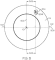
- a line representing a center plane 502 is shown bisecting the transcowl 114 length-wise.
- a cut-away depicted at 504 reveals linkage rod 2041 in the hidden cavity 650 ( FIG. 6 ) in the transcowl 114.
- Linkage rod 2041 is located at a distance, X 506, to the right of the center plane 502.
- linkage rod 2042 is located at a distance X 506 to the left of the center plane 502.
- linkage rods 2081 and 2082 are a distance X 506 from the center plane 502.
- a line representing another bisecting plane 508 is shown perpendicularly intersecting center plane 502 at the thrust reverser centerline 101.
- marker 510 to marker 512 may comprise a "top" half of the transcowl 114 and, clockwise, marker 512 to marker 510 may comprise a "bottom" half of the transcowl 114 (i.e., the two halves completing 360 degrees).
- the side beam 402 is substantially centered at the marker 510, and the side beam 404 is substantially centered at the marker 512 location.
- the pivot axes 202 and 206 extend horizontally, and the center plane 502 extends vertically.
- the thrust reverser when installed on the turbine engine, could be oriented such that the pivot axes 202 and 206 are not horizontal, but are oriented at an angle off of, or relative to, a horizontal. Regardless of the installed orientation of the thrust reverser, the center plane 502 is perpendicular to the pivot axes 202 and 206.
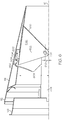
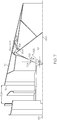
- the linkage rod 2041 is shown coupling an outer surface of the blocker door 1161 at first end 604 to the transcowl 114 at second end 606.
- the hidden cavity 650 is in a space between a blocker door (such as upper blocker door 1161) and inner surface of the transcowl 114 outer layer 302, i.e., it has a "blocker door side” and a “transcowl 114 side” (also referred to as the "transcowl outer layer 302 side").
- the hidden cavity 650 is substantially covered by the respective blocker door.
- all included linkage rod assemblies fit into one or more respective hidden cavities 650. Said differently, regardless of a number of linkage rods and/or linkage rod assemblies present, no linkage rod assembly components are found within the engine exhaust flow 106 when the thrust reverser is stowed, or in the reverse flow path 107 when the thrust reverser is deployed.
- the linkage rods 2041, 2042, 2081, and 2082 and their associated assemblies also do not mount to the side beams or any other component of the stationary structure 108.
- the pivot axis 202 is parallel to a plane passing through the thrust reverser centerline 101, and offset by a distance 610.
- the blocker door 1161 has a radius, R 608, measured from the thrust reverser centerline 101, generally perpendicular to a pivot axis 202 (for the upper blocker door 1161 ) or 206 (for the lower blocker door 1162 ).
- R 608 measured from the thrust reverser centerline 101, generally perpendicular to a pivot axis 202 (for the upper blocker door 1161 ) or 206 (for the lower blocker door 1162 ).
- the distance Y 708 causes the full rotation angle 702 to be substantially 45 degrees, but may be in a range of 35 to 55 degrees.
- the linkage angle 706 in response to the full rotation angle 702 being achieved, the linkage angle 706 to be less than or equal to 15 degrees.
- a ratio of X/R is within the range of 0.4 to 0.7. In various embodiments, a ratio of Y/R is between 0.5 and 0.7.
- an embodiment of a system or a component may employ various integrated circuit components, e.g., memory elements, digital signal processing elements, logic elements, look-up tables, or the like, which may carry out a variety of functions under the control of one or more microprocessors or other control devices.
- integrated circuit components e.g., memory elements, digital signal processing elements, logic elements, look-up tables, or the like, which may carry out a variety of functions under the control of one or more microprocessors or other control devices.
Landscapes
- Engineering & Computer Science (AREA)
- Chemical & Material Sciences (AREA)
- Combustion & Propulsion (AREA)
- Mechanical Engineering (AREA)
- General Engineering & Computer Science (AREA)
- Structures Of Non-Positive Displacement Pumps (AREA)
- Power-Operated Mechanisms For Wings (AREA)
- Sliding-Contact Bearings (AREA)
Applications Claiming Priority (1)
| Application Number | Priority Date | Filing Date | Title |
|---|---|---|---|
| US15/689,218 US10865737B2 (en) | 2017-08-29 | 2017-08-29 | Hidden linkage for a translating cowl thrust reverser |
Publications (2)
| Publication Number | Publication Date |
|---|---|
| EP3450737A1 true EP3450737A1 (fr) | 2019-03-06 |
| EP3450737B1 EP3450737B1 (fr) | 2021-07-28 |
Family
ID=63405132
Family Applications (1)
| Application Number | Title | Priority Date | Filing Date |
|---|---|---|---|
| EP18190869.0A Active EP3450737B1 (fr) | 2017-08-29 | 2018-08-25 | Liaison cachée pour inverseur de poussée de capot de translation et procédé de production |
Country Status (2)
| Country | Link |
|---|---|
| US (1) | US10865737B2 (fr) |
| EP (1) | EP3450737B1 (fr) |
Families Citing this family (2)
| Publication number | Priority date | Publication date | Assignee | Title |
|---|---|---|---|---|
| US11286879B2 (en) * | 2018-07-02 | 2022-03-29 | Rohr, Inc. | Target door reverser wit h non-parallel hinge lines |
| US12071911B1 (en) * | 2023-06-02 | 2024-08-27 | Honeywell International Inc. | Thrust reverser for aerial vehicle |
Citations (5)
| Publication number | Priority date | Publication date | Assignee | Title |
|---|---|---|---|---|
| US2847823A (en) * | 1955-03-15 | 1958-08-19 | Curtiss Wright Corp | Reverse thrust nozzle construction |
| US3779010A (en) * | 1972-08-17 | 1973-12-18 | Gen Electric | Combined thrust reversing and throat varying mechanism for a gas turbine engine |
| US6151885A (en) * | 1997-09-25 | 2000-11-28 | Societe Hispano Suiza Aerostructures | Turbojet-engine thrust reverser with internal clamshells |
| EP3193000A1 (fr) * | 2016-01-18 | 2017-07-19 | Honeywell International Inc. | Inverseur de poussée de capot de translation présentant un déséquilibre de pression réduisant la charge structuralle globale |
| EP3205867A1 (fr) * | 2016-02-09 | 2017-08-16 | Honeywell International Inc. | Système inverseur de poussée de capot de translation avec capacité de déverrouillage surarrimée |
Family Cites Families (20)
| Publication number | Priority date | Publication date | Assignee | Title |
|---|---|---|---|---|
| US3050937A (en) * | 1958-06-09 | 1962-08-28 | Boeing Co | Reversible thrust jet engines and controls therefor |
| US3036431A (en) * | 1959-09-08 | 1962-05-29 | Boeing Co | Thrust reverser for jet engines |
| US3500645A (en) * | 1968-04-10 | 1970-03-17 | Rohr Corp | Thrust reverser |
| US3614037A (en) * | 1969-09-22 | 1971-10-19 | Boeing Co | Aircraft combination thrust reverser and sound suppressor and a particular full range balanced thrust reverser |
| US4340178A (en) | 1980-05-05 | 1982-07-20 | Rohr Industries, Inc. | Thrust reverser - cascade type |
| FR2486153B1 (fr) * | 1980-07-04 | 1985-10-04 | Hurel Dubois Avions | Inverseur de poussee pour moteur a reaction, destine notamment a equiper un aeronef |
| DE3844188C1 (fr) * | 1988-12-29 | 1990-05-17 | Mtu Muenchen Gmbh | |
| US5313788A (en) * | 1991-08-07 | 1994-05-24 | General Electric Company | Thrust reversing arrangement for a long duct mixed flow exhaust turbofan engine |
| US5309711A (en) * | 1991-08-21 | 1994-05-10 | Rohr, Inc. | Cascade type thrust reverser for fan jet engines |
| US5655360A (en) * | 1995-05-31 | 1997-08-12 | General Electric Company | Thrust reverser with variable nozzle |
| EP0852290A1 (fr) * | 1996-12-19 | 1998-07-08 | SOCIETE DE CONSTRUCTION DES AVIONS HUREL-DUBOIS (société anonyme) | Inverseur de poussée de turboréacteur à double flux avec grand taux de dilution |
| US8109466B2 (en) * | 2008-06-23 | 2012-02-07 | Rohr, Inc. | Thrust reverser cascade assembly and AFT cascade ring with flow deflector portion |
| US8109467B2 (en) * | 2009-04-24 | 2012-02-07 | United Technologies Corporation | Thrust reverser assembly with shaped drag links |
| FR2946094B1 (fr) * | 2009-06-02 | 2014-04-18 | Aircelle Sa | Inverseur de poussee pour nacelle de turboreacteur double flux. |
| FR2957979B1 (fr) * | 2010-03-25 | 2012-03-30 | Aircelle Sa | Dispositif d'inversion de poussee |
| FR2982323B1 (fr) * | 2011-11-07 | 2013-11-15 | Aircelle Sa | Dispositif d'inversion de poussee |
| US9447749B2 (en) * | 2013-04-02 | 2016-09-20 | Rohr, Inc. | Pivoting blocker door for thrust reverser |
| US10077739B2 (en) * | 2014-04-24 | 2018-09-18 | Rohr, Inc. | Dual actuation system for cascade and thrust reverser panel for an integral cascade variable area fan nozzle |
| US20160305370A1 (en) | 2015-04-16 | 2016-10-20 | Honeywell International Inc. | Translating cowl thrust reverser with door pivots aft of reverse flow path |
| US10344709B2 (en) * | 2015-09-10 | 2019-07-09 | Honeywell International Inc. | System and method for reducing idle thrust in a translating cowl thrust reverser |
-
2017
- 2017-08-29 US US15/689,218 patent/US10865737B2/en active Active
-
2018
- 2018-08-25 EP EP18190869.0A patent/EP3450737B1/fr active Active
Patent Citations (5)
| Publication number | Priority date | Publication date | Assignee | Title |
|---|---|---|---|---|
| US2847823A (en) * | 1955-03-15 | 1958-08-19 | Curtiss Wright Corp | Reverse thrust nozzle construction |
| US3779010A (en) * | 1972-08-17 | 1973-12-18 | Gen Electric | Combined thrust reversing and throat varying mechanism for a gas turbine engine |
| US6151885A (en) * | 1997-09-25 | 2000-11-28 | Societe Hispano Suiza Aerostructures | Turbojet-engine thrust reverser with internal clamshells |
| EP3193000A1 (fr) * | 2016-01-18 | 2017-07-19 | Honeywell International Inc. | Inverseur de poussée de capot de translation présentant un déséquilibre de pression réduisant la charge structuralle globale |
| EP3205867A1 (fr) * | 2016-02-09 | 2017-08-16 | Honeywell International Inc. | Système inverseur de poussée de capot de translation avec capacité de déverrouillage surarrimée |
Also Published As
| Publication number | Publication date |
|---|---|
| EP3450737B1 (fr) | 2021-07-28 |
| US20190063367A1 (en) | 2019-02-28 |
| US10865737B2 (en) | 2020-12-15 |
Similar Documents
| Publication | Publication Date | Title |
|---|---|---|
| US10344709B2 (en) | System and method for reducing idle thrust in a translating cowl thrust reverser | |
| US10859035B2 (en) | Composite translating cowl assembly for a thrust reverser system | |
| US10648426B2 (en) | Single row vane assembly for a thrust reverser | |
| EP3196453B1 (fr) | Inverseur de poussée à géométrie d'aube asymétrique | |
| US11060481B2 (en) | Translating cowl thrust reverser system with over-stow unlocking capability | |
| EP3081796A1 (fr) | Inverseur de poussée comprenant des portes pivotables | |
| EP3293388B1 (fr) | Ferrure de bras de liaison de porte de blocage inverseur de poussée caché | |
| EP3293387B1 (fr) | Ferrure de bras de liaison de porte de blocage à inverseur de poussée caché | |
| US10267262B2 (en) | Thrust reverser assembly | |
| EP3196452B1 (fr) | Inverseur de poussée de capot de translation empêchant une rotation de porte involontaire | |
| EP3193000A1 (fr) | Inverseur de poussée de capot de translation présentant un déséquilibre de pression réduisant la charge structuralle globale | |
| US10865737B2 (en) | Hidden linkage for a translating cowl thrust reverser | |
| EP4141247A1 (fr) | Système inverseur de poussée de capot de translation avec gestion d'efflux | |
| EP3587783B1 (fr) | Étrésillon pliable |
Legal Events
| Date | Code | Title | Description |
|---|---|---|---|
| PUAI | Public reference made under article 153(3) epc to a published international application that has entered the european phase |
Free format text: ORIGINAL CODE: 0009012 |
|
| STAA | Information on the status of an ep patent application or granted ep patent |
Free format text: STATUS: REQUEST FOR EXAMINATION WAS MADE |
|
| 17P | Request for examination filed |
Effective date: 20180825 |
|
| AK | Designated contracting states |
Kind code of ref document: A1 Designated state(s): AL AT BE BG CH CY CZ DE DK EE ES FI FR GB GR HR HU IE IS IT LI LT LU LV MC MK MT NL NO PL PT RO RS SE SI SK SM TR |
|
| AX | Request for extension of the european patent |
Extension state: BA ME |
|
| GRAP | Despatch of communication of intention to grant a patent |
Free format text: ORIGINAL CODE: EPIDOSNIGR1 |
|
| STAA | Information on the status of an ep patent application or granted ep patent |
Free format text: STATUS: GRANT OF PATENT IS INTENDED |
|
| INTG | Intention to grant announced |
Effective date: 20210326 |
|
| GRAS | Grant fee paid |
Free format text: ORIGINAL CODE: EPIDOSNIGR3 |
|
| GRAA | (expected) grant |
Free format text: ORIGINAL CODE: 0009210 |
|
| STAA | Information on the status of an ep patent application or granted ep patent |
Free format text: STATUS: THE PATENT HAS BEEN GRANTED |
|
| AK | Designated contracting states |
Kind code of ref document: B1 Designated state(s): AL AT BE BG CH CY CZ DE DK EE ES FI FR GB GR HR HU IE IS IT LI LT LU LV MC MK MT NL NO PL PT RO RS SE SI SK SM TR |
|
| REG | Reference to a national code |
Ref country code: GB Ref legal event code: FG4D |
|
| REG | Reference to a national code |
Ref country code: CH Ref legal event code: EP |
|
| REG | Reference to a national code |
Ref country code: AT Ref legal event code: REF Ref document number: 1414937 Country of ref document: AT Kind code of ref document: T Effective date: 20210815 |
|
| REG | Reference to a national code |
Ref country code: IE Ref legal event code: FG4D |
|
| REG | Reference to a national code |
Ref country code: DE Ref legal event code: R096 Ref document number: 602018020691 Country of ref document: DE |
|
| REG | Reference to a national code |
Ref country code: LT Ref legal event code: MG9D |
|
| REG | Reference to a national code |
Ref country code: NL Ref legal event code: MP Effective date: 20210728 |
|
| REG | Reference to a national code |
Ref country code: AT Ref legal event code: MK05 Ref document number: 1414937 Country of ref document: AT Kind code of ref document: T Effective date: 20210728 |
|
| PG25 | Lapsed in a contracting state [announced via postgrant information from national office to epo] |
Ref country code: LT Free format text: LAPSE BECAUSE OF FAILURE TO SUBMIT A TRANSLATION OF THE DESCRIPTION OR TO PAY THE FEE WITHIN THE PRESCRIBED TIME-LIMIT Effective date: 20210728 Ref country code: AT Free format text: LAPSE BECAUSE OF FAILURE TO SUBMIT A TRANSLATION OF THE DESCRIPTION OR TO PAY THE FEE WITHIN THE PRESCRIBED TIME-LIMIT Effective date: 20210728 Ref country code: BG Free format text: LAPSE BECAUSE OF FAILURE TO SUBMIT A TRANSLATION OF THE DESCRIPTION OR TO PAY THE FEE WITHIN THE PRESCRIBED TIME-LIMIT Effective date: 20211028 Ref country code: PT Free format text: LAPSE BECAUSE OF FAILURE TO SUBMIT A TRANSLATION OF THE DESCRIPTION OR TO PAY THE FEE WITHIN THE PRESCRIBED TIME-LIMIT Effective date: 20211129 Ref country code: NO Free format text: LAPSE BECAUSE OF FAILURE TO SUBMIT A TRANSLATION OF THE DESCRIPTION OR TO PAY THE FEE WITHIN THE PRESCRIBED TIME-LIMIT Effective date: 20211028 Ref country code: NL Free format text: LAPSE BECAUSE OF FAILURE TO SUBMIT A TRANSLATION OF THE DESCRIPTION OR TO PAY THE FEE WITHIN THE PRESCRIBED TIME-LIMIT Effective date: 20210728 Ref country code: SE Free format text: LAPSE BECAUSE OF FAILURE TO SUBMIT A TRANSLATION OF THE DESCRIPTION OR TO PAY THE FEE WITHIN THE PRESCRIBED TIME-LIMIT Effective date: 20210728 Ref country code: RS Free format text: LAPSE BECAUSE OF FAILURE TO SUBMIT A TRANSLATION OF THE DESCRIPTION OR TO PAY THE FEE WITHIN THE PRESCRIBED TIME-LIMIT Effective date: 20210728 Ref country code: HR Free format text: LAPSE BECAUSE OF FAILURE TO SUBMIT A TRANSLATION OF THE DESCRIPTION OR TO PAY THE FEE WITHIN THE PRESCRIBED TIME-LIMIT Effective date: 20210728 Ref country code: ES Free format text: LAPSE BECAUSE OF FAILURE TO SUBMIT A TRANSLATION OF THE DESCRIPTION OR TO PAY THE FEE WITHIN THE PRESCRIBED TIME-LIMIT Effective date: 20210728 Ref country code: FI Free format text: LAPSE BECAUSE OF FAILURE TO SUBMIT A TRANSLATION OF THE DESCRIPTION OR TO PAY THE FEE WITHIN THE PRESCRIBED TIME-LIMIT Effective date: 20210728 |
|
| PG25 | Lapsed in a contracting state [announced via postgrant information from national office to epo] |
Ref country code: PL Free format text: LAPSE BECAUSE OF FAILURE TO SUBMIT A TRANSLATION OF THE DESCRIPTION OR TO PAY THE FEE WITHIN THE PRESCRIBED TIME-LIMIT Effective date: 20210728 Ref country code: LV Free format text: LAPSE BECAUSE OF FAILURE TO SUBMIT A TRANSLATION OF THE DESCRIPTION OR TO PAY THE FEE WITHIN THE PRESCRIBED TIME-LIMIT Effective date: 20210728 Ref country code: GR Free format text: LAPSE BECAUSE OF FAILURE TO SUBMIT A TRANSLATION OF THE DESCRIPTION OR TO PAY THE FEE WITHIN THE PRESCRIBED TIME-LIMIT Effective date: 20211029 |
|
| REG | Reference to a national code |
Ref country code: CH Ref legal event code: PL |
|
| REG | Reference to a national code |
Ref country code: BE Ref legal event code: MM Effective date: 20210831 |
|
| PG25 | Lapsed in a contracting state [announced via postgrant information from national office to epo] |
Ref country code: LI Free format text: LAPSE BECAUSE OF NON-PAYMENT OF DUE FEES Effective date: 20210831 Ref country code: DK Free format text: LAPSE BECAUSE OF FAILURE TO SUBMIT A TRANSLATION OF THE DESCRIPTION OR TO PAY THE FEE WITHIN THE PRESCRIBED TIME-LIMIT Effective date: 20210728 Ref country code: CH Free format text: LAPSE BECAUSE OF NON-PAYMENT OF DUE FEES Effective date: 20210831 |
|
| REG | Reference to a national code |
Ref country code: DE Ref legal event code: R097 Ref document number: 602018020691 Country of ref document: DE |
|
| PG25 | Lapsed in a contracting state [announced via postgrant information from national office to epo] |
Ref country code: SM Free format text: LAPSE BECAUSE OF FAILURE TO SUBMIT A TRANSLATION OF THE DESCRIPTION OR TO PAY THE FEE WITHIN THE PRESCRIBED TIME-LIMIT Effective date: 20210728 Ref country code: SK Free format text: LAPSE BECAUSE OF FAILURE TO SUBMIT A TRANSLATION OF THE DESCRIPTION OR TO PAY THE FEE WITHIN THE PRESCRIBED TIME-LIMIT Effective date: 20210728 Ref country code: RO Free format text: LAPSE BECAUSE OF FAILURE TO SUBMIT A TRANSLATION OF THE DESCRIPTION OR TO PAY THE FEE WITHIN THE PRESCRIBED TIME-LIMIT Effective date: 20210728 Ref country code: MC Free format text: LAPSE BECAUSE OF FAILURE TO SUBMIT A TRANSLATION OF THE DESCRIPTION OR TO PAY THE FEE WITHIN THE PRESCRIBED TIME-LIMIT Effective date: 20210728 Ref country code: LU Free format text: LAPSE BECAUSE OF NON-PAYMENT OF DUE FEES Effective date: 20210825 Ref country code: EE Free format text: LAPSE BECAUSE OF FAILURE TO SUBMIT A TRANSLATION OF THE DESCRIPTION OR TO PAY THE FEE WITHIN THE PRESCRIBED TIME-LIMIT Effective date: 20210728 Ref country code: CZ Free format text: LAPSE BECAUSE OF FAILURE TO SUBMIT A TRANSLATION OF THE DESCRIPTION OR TO PAY THE FEE WITHIN THE PRESCRIBED TIME-LIMIT Effective date: 20210728 Ref country code: AL Free format text: LAPSE BECAUSE OF FAILURE TO SUBMIT A TRANSLATION OF THE DESCRIPTION OR TO PAY THE FEE WITHIN THE PRESCRIBED TIME-LIMIT Effective date: 20210728 |
|
| PLBE | No opposition filed within time limit |
Free format text: ORIGINAL CODE: 0009261 |
|
| STAA | Information on the status of an ep patent application or granted ep patent |
Free format text: STATUS: NO OPPOSITION FILED WITHIN TIME LIMIT |
|
| 26N | No opposition filed |
Effective date: 20220429 |
|
| PG25 | Lapsed in a contracting state [announced via postgrant information from national office to epo] |
Ref country code: IT Free format text: LAPSE BECAUSE OF FAILURE TO SUBMIT A TRANSLATION OF THE DESCRIPTION OR TO PAY THE FEE WITHIN THE PRESCRIBED TIME-LIMIT Effective date: 20210728 Ref country code: IE Free format text: LAPSE BECAUSE OF NON-PAYMENT OF DUE FEES Effective date: 20210825 Ref country code: FR Free format text: LAPSE BECAUSE OF NON-PAYMENT OF DUE FEES Effective date: 20210928 Ref country code: BE Free format text: LAPSE BECAUSE OF NON-PAYMENT OF DUE FEES Effective date: 20210831 |
|
| GBPC | Gb: european patent ceased through non-payment of renewal fee |
Effective date: 20220825 |
|
| PG25 | Lapsed in a contracting state [announced via postgrant information from national office to epo] |
Ref country code: CY Free format text: LAPSE BECAUSE OF FAILURE TO SUBMIT A TRANSLATION OF THE DESCRIPTION OR TO PAY THE FEE WITHIN THE PRESCRIBED TIME-LIMIT Effective date: 20210728 |
|
| P01 | Opt-out of the competence of the unified patent court (upc) registered |
Effective date: 20230525 |
|
| PG25 | Lapsed in a contracting state [announced via postgrant information from national office to epo] |
Ref country code: HU Free format text: LAPSE BECAUSE OF FAILURE TO SUBMIT A TRANSLATION OF THE DESCRIPTION OR TO PAY THE FEE WITHIN THE PRESCRIBED TIME-LIMIT; INVALID AB INITIO Effective date: 20180825 |
|
| PG25 | Lapsed in a contracting state [announced via postgrant information from national office to epo] |
Ref country code: GB Free format text: LAPSE BECAUSE OF NON-PAYMENT OF DUE FEES Effective date: 20220825 |
|
| PG25 | Lapsed in a contracting state [announced via postgrant information from national office to epo] |
Ref country code: MK Free format text: LAPSE BECAUSE OF FAILURE TO SUBMIT A TRANSLATION OF THE DESCRIPTION OR TO PAY THE FEE WITHIN THE PRESCRIBED TIME-LIMIT Effective date: 20210728 |
|
| PG25 | Lapsed in a contracting state [announced via postgrant information from national office to epo] |
Ref country code: TR Free format text: LAPSE BECAUSE OF FAILURE TO SUBMIT A TRANSLATION OF THE DESCRIPTION OR TO PAY THE FEE WITHIN THE PRESCRIBED TIME-LIMIT Effective date: 20210728 |
|
| PG25 | Lapsed in a contracting state [announced via postgrant information from national office to epo] |
Ref country code: MT Free format text: LAPSE BECAUSE OF FAILURE TO SUBMIT A TRANSLATION OF THE DESCRIPTION OR TO PAY THE FEE WITHIN THE PRESCRIBED TIME-LIMIT Effective date: 20210728 |
|
| PGFP | Annual fee paid to national office [announced via postgrant information from national office to epo] |
Ref country code: DE Payment date: 20250827 Year of fee payment: 8 |